

Page 1
DECIMATE™
Data Sheet May 1999
IntersilHSP43220 Decimating Digital Filter
Development Software
Intersil DECIMATE Development Software assiststhedesign
engineer to prototype designs for the Intersil HSP43220
Decimating Digital filter (DDF). Developed specificallyfor the
DDF, this software consists of three integrated modules:
DDF Design, DDF Simulator and DDF PROM. The Design
module designs a filter from a set of user specifications for
the DDF. The Simulator module models the DDF’s internal
operation. The PROM module uses the device configuration
created by the Design module to build a PROM data file that
can be used to store and download the DDF configuration.
DDF System Design
The DDF consists of two stages: a High Decimation Filter
(HDF) and a Finite Impulse Response (FIR) filter. Together
these providea unique narrowband, lowpass filter.Because of
this unique architecture, special software is required to
configure the device for a giv en set of filter parameters . This
software uses system level filter par ameters (listed below) to
perform the trade off analysis and calculate the values for the
DDF’s Configuration Registers and FIR coefficients.
Design specifications are supplied by the user in terms of:
1. Input sample frequency.
2. Required output sample frequency.
3. Passband signal bandwidth.
4. Transition bandwidth.
5. Amount of attenuation allowed in the passband.
6. Amount of stopband attenuation required for signals
outside of the band of interest.
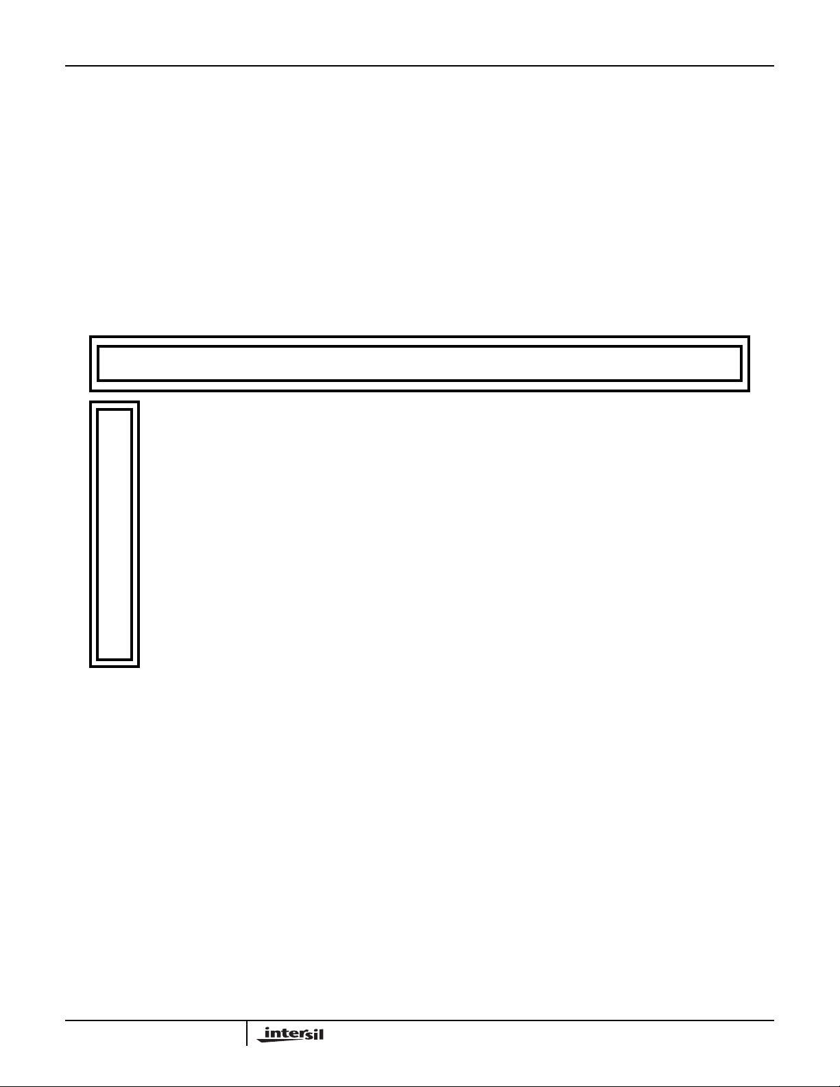
This information is entered into a menu screen (See Figure
1), providing immediate feedback on the design validity.The
design module calculates the order of the HDF, HDF
decimation required, the FIR input data rate, minimum clock
frequency for the FIR, FIR order and decimation required in
the FIR.
The design module will then generate the FIR filter. Four
different methods are provided for the FIR design:
1. A Standard FIR automatically designed by the module
using the Parks-McClellan method to compute the
coefficients of an equiripple (Chebyshev) filter.
2. Any FIR imported into the Design module from another
FIR design program.
3. A precompensated FIR which is automatically designed
by the module to compensate for the roll-off in the
passband of the HDF frequency response.
4. The FIR may alsobe bypassedin which case the optimal
HDF is designed from the user specifications.
File Number
Frequency response curves are then displayed showing the
resulting responses in the HDF, FIR and for the entire chip
using the givenfilter design. Figure 2 is a typical display.The
user may save this frequency response data for further
analysis. The design module also creates a report file
documenting the filter design and providing the coefficients
and setup register values for programming the device.
3368.1
DDF Simulator
The simulator provides an accurate simulation of the device
before any hardware is built. It can be used to simulate any
filter designed with DECIMATE. The simulator takes into
account the fixed point bus widths and pipeline delays for
every element in the DDF.
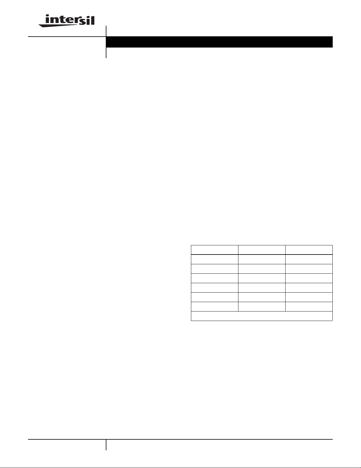
The simulator provides the user with an input signal which
can be usedto stimulate the filter.This signal is created from
the options shown in Table 1. The user can select a pure
step, impulse, cosine, chirp, uniform or Gaussian noise as
the input signal, or a morecomplex signal can be generated
by combining that data with an option selected from the
Signal #2 column, with the combining operator chosen from
the middle column. The user can also import a signal from
an outside source.
TABLE 1.
SIGNAL #1 OPERATION SIGNAL #2
Step Step
Impulse No Operation Impulse
COSlNE Add COSINE
Chirp Concatenate Chirp
Uniform Noise Multiply Uniform Noise
Gaussian Noise Gaussian Noise
Imported From Outside
Probes are provided to select specific areas to graphically
display data values, as w ell as sa v e into data files f or further
processing. The DDF Simulator has two lev els; the DDF
Simulator Specification Screen and the DDF Simulator Main
Screen.
The Specification Screen (see Figure 3) is used to input the
simulation parameters. The user selects display modes in
either continuous or decimated format and data formats in
either decimal or hexadecimal. The Specification Screen
also provides for selection of the input signal.
The simulator main screen (see Figure 4) defines the
simulator test probes and displays the data values per clock
cycle. The interactive simulator screen consists of the
HSP43220 Block Diagram, test probes and register
1
CAUTION: These devices are sensitive to electrostatic discharge; follow proper IC Handling Procedures.
http://www.intersil.com or 407-727-9207 | Copyright © Intersil Corporation 1999
DECIMATE™ is a trademark of Intersil Corporation.
Page 2
DECIMATE
contents. The user selects the step size of the input sample
clock and also selects the probes to be monitored. The
simulator will then clock through the specified number of
clock cycles and display the resulting timedomain response.
Figure 5 shows a typical probe display.
Monarch 2.0 DSP Design Software
DECIMATE is fully integrated with Monarch 2.0 professional
DSP design software. Monarch is a full featured DSP
package with FIR lIR filter design and analysis, two
dimensional and three dimensional viewing, a
programmable signal/systems laboratory with 100 +
DSP/Math functions, extensive fixed-point support and
S
DESIGN MODULE SIMULATOR MODULE PROM MODULE
HSP43220 DDF FILTER SPECIFICATION
Filter File
Input Sample Rate
D
E
C
I
M
Output Rate
Passband
Transition Band
Passband Atten
Stopband Atten
FIR Type STANDARD
A
T
E
HDF Order
HDF Decimation
HDF Scale Factor
:
:
:
:
:
:
:
:
:
:
:
PRES.DDF
330
0.6903
FFTs/IFETs Monarch is available separately from The
Athena Group, Inc.
When used with Monarch 2.0, DECIMATE becomes a full
feature design environment for a DSP system. Data can
easily be transferred from DECIMATE modules to the
Monarch modules for further analysis.
System Requirements
IBM PC™, XT™, AT™, PS/2 computer or 100% compatible
with 640K RAM running MS/PC-DOS 2.0 or higher One
MegaByte of fixed-disk space with 5.25” or3.5” floppy drive.
CGA, MCGA, EGA, VGA, 8514, or Hercules Graphics
Adapter. A Math coprocessor is strongly recommended.
33
100
700
96
4
MHz
kHz
kHz
5
Hz
dB
1
dB
Design Mode
Generate Report
Display Response
Save Freq Responses
Save FIR Response
FIR Input Rate
FIR Clock (min)
FIR Order
FIR Decimation
:
:
:
:
100
509
33
:
:
:
:
:
1
AUTO
YES
LOG
YES
YES
kHz
MHz
FIGURE 1. FILTER SPECIFICATION MENU
2
IBM PC, XT, AT, PS/2™ are trademarks of IBM Corporation.
Page 3

DECIMATE
HDF Frequency Response
-3.2192
-50.4144
-97.6096
Magnitude (dB)
-144.804
-192
0 4e+06 8e+06 1e+07 1e+07
System Frequency Response
-0.0065
-47.6682
-95.3298
Frequency (Hz)
FIR Frequency Response
-3.2201
-33.9581
-71.1364
Magnitude (dB)
-108.314
-145.493
0
1e+04 2e+04 3e+04 5e+04
Frequency (Hz)
-142.991
Magnitude (dB)
-190.653
-238.314
0 10000 20000 30000 40000 50000
Frequency (Hz)
FIGURE 2. FREQUENCY DISPLAY
3
Page 4

DECIMATE
DESIGN MODULE SIMULATOR MODULE PROM MODULE
HSP43220 DDF FILTER SPECIFICATION
D
E
C
I
M
A
T
E
DDFDES
DDFSIM
DDFPROM
Filter File
Probe Display
Save Cont. Output
Display Mode
:
:
:
:
PRES.DAR
HEX
YES
CONTINUOUS
INPUT SIGNAL SPECIFICATION
Signal Origin
:
GENERATED
Amplitude
Signal #1
Operator
Signal #2
DESIGN VIEW ANALYSIS CONFIG OSSHELLENHANCEMENTS
COSINE
:
:
:
+
GAUSS
FIGURE 3. SPECIFICATION MENU
HSP43220 DDF SIMULATOR - MAIN
1.00
Mean StdDev
0.00 0.500000
Input Rate
Output Rate
Frequency
5 kHz
:
:
100
Phase
0.00
33
MHz
kHz
INIG R0 COMB FIR
0 0
0 0
Out_selh HIGH
Out_selh LOW
Step Size
Number Samples In
Number Samples Out
FIGURE 4. SIMULATOR - MAIN MENU
0
000000
000000
:
:
:
1
0
0
4
Page 5

PROBE #0
1.0999
0.9999
0.8999
PROBE #1
6.70E + 07
3.35E + 07
42954
PROBE #2
6.70E + 07
3.44E + 07
DECIMATE
511.5
0 511.5 1023
10230
2723756
PROBE #3
0.9536
0.4768
PROBE #4
0.9621
0.4581
-0.0458
58290
0
58290
01428
FIGURE 5. SIMULATOR PROBE DISPLAY
All Intersil semiconductor products are manufactured, assembled and tested under ISO9000 quality systems certification.
Intersil semiconductor products are sold by description only. Intersil Corporation reserves the right to make changes in circuit design and/or specifications at any time without notice. Accordingly, the reader is cautioned to verify that data sheets are current before placing orders. Information furnished by Intersil is believed to be accurate and
reliable. However, no responsibility is assumed by Intersil or its subsidiaries for its use; nor for any infringements of patents or other rights of third parties which may result
from its use. No license is granted by implication or otherwise under any patent or patent rights of Intersil or its subsidiaries.
For information regarding Intersil Corporation and its products, see web site http://www.intersil.com
Sales Office Headquarters
NORTH AMERICA
Intersil Corporation
P. O. Box 883, Mail Stop 53-204
Melbourne, FL 32902
TEL: (407) 724-7000
FAX: (407) 724-7240
5
EUROPE
Intersil SA
Mercure Center
100, Rue de la Fusee
1130 Brussels, Belgium
TEL: (32) 2.724.2111
FAX: (32) 2.724.22.05
ASIA
Intersil (Taiwan) Ltd.
7F-6, No. 101 Fu Hsing North Road
Taipei, Taiwan
Republic of China
TEL: (886) 2 2716 9310
FAX: (886) 2 2715 3029
 Loading...