

Page 1
查询CFH400供应商
CFH 400
Preliminary Datasheet
Low-Noise, High-Linearity Packaged pHEMT FET
Description:
The CFH 400 is a high-linearity pHEMT FET that
exhibits both a high intercept point and low noise
figure. The device is suitable for front-end
applications to 4 GHz such as PCS CDMA and
UMTS receivers, base stations LNAs, and WLAN
front-ends. The device achieves a noise figure as
low as 0.55 dB with 15 dB associated gain at 1.8
GHz. It is packaged in a low-cost SOT343
package and is 100% DC tested before
packaging/RF LAT after packaging.
Applications:
• PCS CDMA and UMTS
Receivers
• WLAN Multicarrier
Receivers
• Basestations
Features:
• Low Noise figure and high associated gain
for high IP3 receivers stages
• Frequencies to 4 GHz
• NF=0.55 dB; Ga=15.7 dB @ f=1.8 GHz,
3V, 10 mA
• Low cost miniature SOT343 package
• Lg = 0.4um; Wg = 400um
• Tape and reel packaging
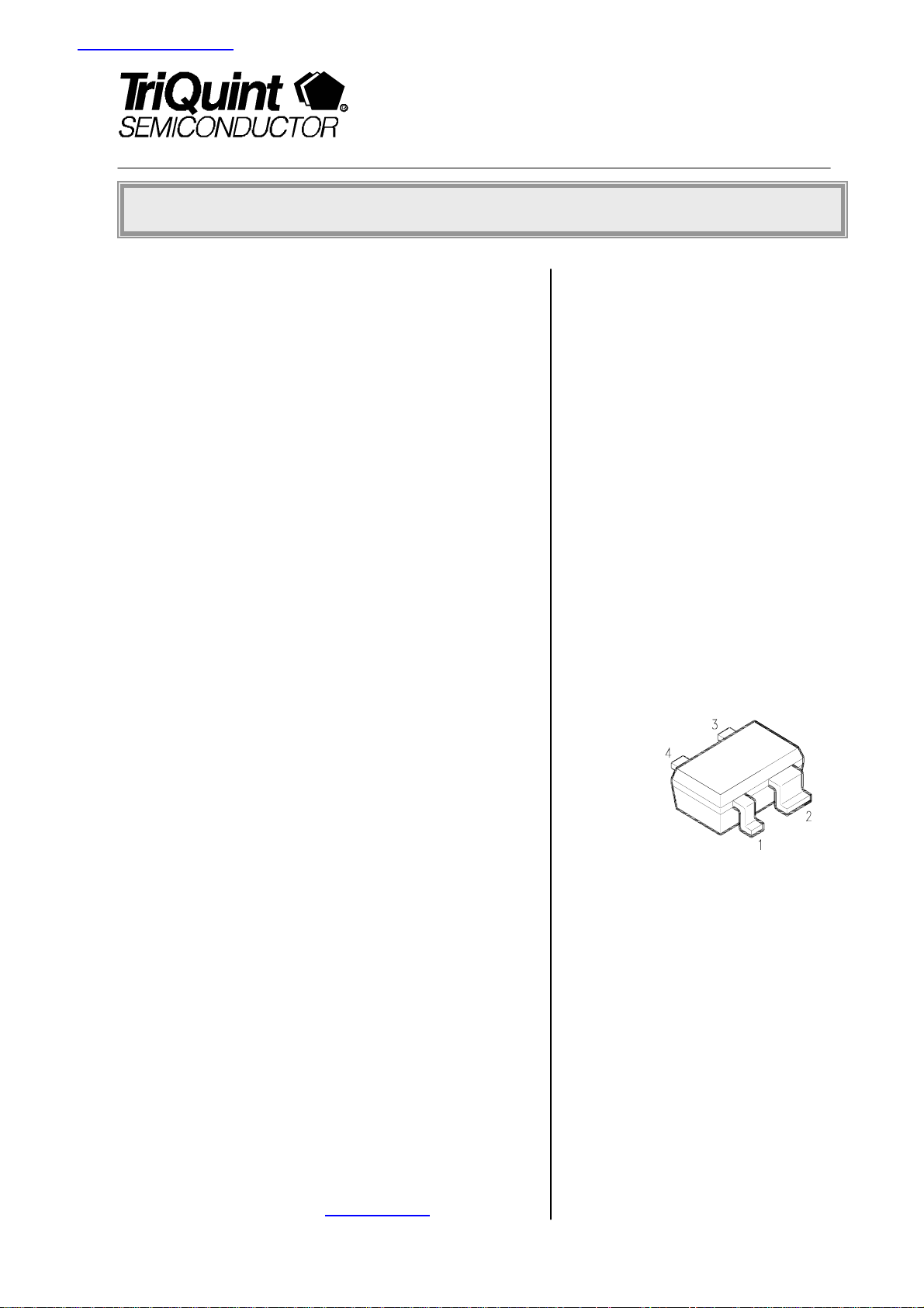
Package Outline,
SOT343:
Pin assignment:
1 = gate
2 = source
3 = drain
4 = source
For further information please visit www.triquint.com pg. 1/6
Rev. 1.2; May 29th, 2003
Page 2
CFH 400 Preliminary Datasheet
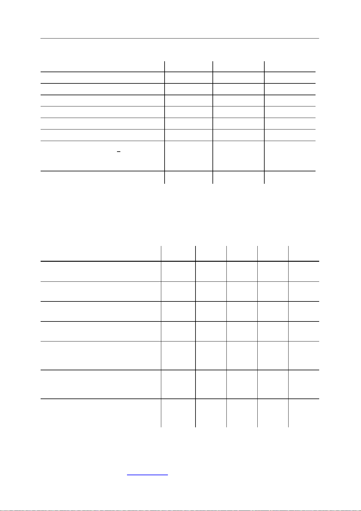
Maximum Ratings:
Parameter Symbol Unit
Drain-source voltage VDS 5.5 V
Drain-gate voltage VDG 6.5 V
Gate-source voltage VGS -2.0 V
Drain current ID 80 mA
Channel temperature TCh 150 °C
Storage temperature range T
Total power dissipation (TS < tbd°C) 2
-65...+150 °C
stg
P
150 mW
tot
Thermal resistance
Channel-soldering point source R
1) Dimensions see page 4
2) TS: Temperature measured at soldering point
thChS
166 K/W
Electrical characteristics:
at TA = 25°C unless otherwise specified
Characteristics Symbol min typ max Unit
Drain-source saturation current
VDS = 3 V VGS = 0 V
Pinch-off voltage
VDS = 3 V ID = 1 mA
Gate leakage current
VDS = 3 V ID = 15 mA
I
DSS
V
GS(P)
IG
0
-0.7
-
40
-0.25
-
70
0
5
mA
V
µA
Transconductance
VDS = 3 V ID = 15 mA
Noise figure*
VDS = 3 V ID = 10 mA f = 1.8 GHz
VDS = 3 V ID = 15 mA f = 1.8 GHz
Associated gain*
VDS = 3 V ID = 10 mA f = 1.8 GHz
VDS = 3 V ID = 15 mA f = 1.8 GHz
IIP3*
VDS = 3 V ID = 10 mA f = 1.8 GHz
VDS = 3 V ID = 15 mA f = 1.8 GHz
gm
F
Ga
IIP3
70
-
-
-
100
0.55
0.53
15.7
16.2
6
8.5
-
-
-
-
* Parameters are measured at input impedance for minimum noise figure and output
impedance for maximum gain.
For further information please visit www.triquint.com
Rev. 1.2; May 29th, 2003
pg. 2/6
mS
dB
dB
dBm
Page 3

CFH 400 Preliminary Datasheet
Electrical Characteristics, Continued:
Typical Common Source S – Parameters
@ 3V; 10mA; Zo = 50Ω
f[GHz] S11 Mag S11 Ang S21 Mag S21 Ang S12 Mag S12 Ang S22 Mag S22 Ang
0.2 0.9818 -6.3 8.2506 174.6 0.0128 110.7 0.7321 -5.3
0.3 0.9947 -11.8 8.3347 170.2 0.0198 91.2 0.7148 -10.4
0.4 0.9826 -17.9 8.166 164.2 0.0288 95 0.7114 -15.5
0.5 0.9696 -23.8 8.1183 159.5 0.041 72 0.6999 -20.6
0.6 0.9525 -30.1 8.0562 154.2 0.0512 71.1 0.6835 -26.1
0.7 0.9312 -36 7.9081 149.9 0.0596 66.2 0.6651 -30.8
0.8 0.9159 -41.8 7.7814 144.7 0.0666 62.8 0.6434 -36
0.9 0.8956 -47.6 7.6295 140 0.0724 58.3 0.6203 -41.1
1 0.8702 -52.9 7.4436 135 0.0799 55.5 0.5925 -46.3
1.1 0.8444 -58.7 7.2593 130.8 0.0889 51.7 0.574 -51.8
1.2 0.8144 -64.8 7.0517 126.4 0.0938 50.1 0.5488 -57.4
1.3 0.7919 -70.7 6.8482 121.8 0.0994 45.4 0.5257 -62.9
1.4 0.7663 -76 6.7195 117.8 0.1056 42.3 0.5006 -68.4
1.5 0.7438 -81.9 6.4735 114 0.1097 40.4 0.477 -73.9
1.6 0.7208 -87 6.2591 109.9 0.1124 37.2 0.4587 -79.1
1.7 0.6956 -92 6.0662 106.2 0.1158 33.9 0.4444 -85
1.8 0.6788 -97.3 5.8346 102.3 0.1195 31.6 0.4217 -90.5
1.9 0.6579 -102.6 5.6395 98.9 0.1225 30.6 0.4055 -95.2
2 0.6396 -107.5 5.4822 95.5 0.1248 27 0.3913 -101.5
2.1 0.6214 -111.8 5.3077 92.2 0.1245 24.7 0.3843 -106.5
2.2 0.6048 -116.9 5.0469 89 0.1274 23.4 0.3738 -111.7
2.3 0.5949 -121 4.8822 86.2 0.1306 21.4 0.3663 -117.1
2.4 0.5831 -125.4 4.7575 83.1 0.1313 19.1 0.3644 -121
2.5 0.5724 -129.4 4.607 80.5 0.1323 18 0.355 -126.8
3 0.5315 -147.8 3.9289 67.4 0.1364 11.5 0.3447 -145.9
3.5 0.5065 -163.5 3.4181 56 0.1396 7 0.3463 -159.9
4 0.4948 -176.1 3.0368 45.5 0.1397 1.6 0.3449 -171.5
4.5 0.4889 171.3 2.7496 35.3 0.1439 -1.8 0.3429 178
5 0.491 159.7 2.5187 25.1 0.1494 -5.7 0.3405 166.8
Typical Common Source Noise – Parameters
@ 3V; 10mA; Zo = 50Ω
f[GHz] F
[dB] Ga [dB]
min
Mag (Γopt ) Phase(Γopt) [deg]
Rn/50
0.9 0.42 19.9 0.73 13 0.20
1.8 0.55 15.7 0.57 35 0.16
2.4 0.60 13.7 0.45 51 0.17
3.0 0.67 12.7 0.35 72 0.13
4.0 0.70 10.7 0.33 107 0.10
For further information please visit www.triquint.com
Rev. 1.2; May 29th, 2003
pg. 3/6
Page 4

CFH 400 Preliminary Datasheet
Electrical Characteristics, Continued:
Typical Common Source S – Parameters
@ 3V; 15mA; Zo = 50Ω
f[GHz] S11 Mag S11 Ang S21 Mag S21 Ang S12 Mag S12 Ang S22 Mag S22 Ang
0.2 0.9995 -4.3 9.9975 174.5 0.0168 128.9 0.6751 -6.1
0.3 0.9933 -13.3 10.0492 168.8 0.02 93.3 0.6764 -11.2
0.4 0.9788 -20.1 9.8365 163 0.0259 84.5 0.67 -16.9
0.5 0.9604 -26.7 9.7307 157.4 0.038 71.5 0.6521 -23.4
0.6 0.9348 -33.6 9.6242 151.7 0.047 68.3 0.6349 -28.9
0.7 0.9115 -40.1 9.412 147.2 0.0503 65.5 0.6091 -34.2
0.8 0.8924 -46.6 9.1204 141.8 0.0596 60.5 0.5844 -40.2
0.9 0.8721 -52.6 8.9181 136.5 0.0715 56.7 0.5641 -45.9
1 0.8457 -59 8.569 131.6 0.0769 52.3 0.5325 -51.9
1.1 0.8144 -65.1 8.3702 127.2 0.0817 49.6 0.5124 -57.4
1.2 0.788 -71.2 8.0757 122.3 0.0869 46 0.4814 -62.7
1.3 0.7555 -77.2 7.821 117.9 0.0903 44.2 0.4603 -69.1
1.4 0.7317 -83.5 7.548 114.3 0.0971 41.1 0.4369 -74.5
1.5 0.7136 -89.2 7.2741 110.1 0.1005 37.8 0.4155 -80.9
1.6 0.6862 -94.7 6.9825 106.5 0.1027 37.1 0.3947 -86.4
1.7 0.6595 -100.1 6.69 103 0.1054 34.3 0.3836 -93.2
1.8 0.6437 -105.3 6.4121 98.9 0.108 31.8 0.368 -99
1.9 0.6195 -110.4 6.1979 95.4 0.1108 29.3 0.351 -104.6
2 0.6053 -115.3 5.9347 92.5 0.1135 28.8 0.3428 -110
2.1 0.5946 -120.1 5.7644 89.3 0.1144 26.5 0.334 -116.1
2.2 0.5814 -124.6 5.5403 86 0.1146 24.6 0.3294 -121.3
2.3 0.5675 -129 5.3237 83.2 0.1167 23.6 0.3265 -125.8
2.4 0.5583 -133.5 5.1687 80.5 0.1179 22.6 0.3213 -130.9
2.5 0.5487 -137.4 4.918 78 0.1177 20.9 0.3168 -135.6
3 0.5182 -155.5 4.2195 65.3 0.125 15.1 0.3195 -154.7
3.5 0.4985 -170.8 3.6443 54.2 0.1279 10.8 0.3212 -168.6
4 0.4876 176.6 3.2225 44.4 0.1328 6.9 0.3248 -178.3
4.5 0.4873 165.8 2.9196 34.6 0.1377 3.3 0.3252 171.5
5 0.4795 153.7 2.6297 24.4 0.1436 0.5 0.3221 159.9
Typical Common Source Noise – Parameters
@ 3V; 15mA; Zo = 50Ω
f[GHz] F
[dB] Ga [dB]
min
Mag (Γopt ) Phase(Γopt) [deg]
Rn/50
0.9 0.40 20.4 0.74 13 0.18
1.8 0.53 16.2 0.57 30 0.15
2.4 0.58 14.3 0.39 52 0.14
3.0 0.63 13.0 0.31 78 0.12
4.0 0.68 11.0 0.29 109 0.10
For further information please visit www.triquint.com
Rev. 1.2; May 29th, 2003
pg. 4/6
Page 5

CFH 400 Preliminary Datasheet
Semiconductor Device Outline SOT343
Pin assignment:
1 = gate
2 = source
3 = drain
4 = source
For further information please visit www.triquint.com
Rev. 1.2; May 29th, 2003
pg. 5/6
Page 6

CFH 400 Preliminary Datasheet
Ordering Information:
Type Marking Ordering code
(taped)
Package
CFH400 N4s Q62702-G0116 SOT343
ESD: Electrostatic discharge sensitive device, observe handling precautions!
Published by TriQuint Semiconductor GmbH, Marketing, Konrad-Zuse-Platz 1, D-81829
Munich.
copyright TriQuint Semiconductor GmbH 2003. All Rights Reserved.
As far as patents or other rights of third parties are concerned, liability is only assumed for
components per se, not for applications, processes and circuits implemented within
components or assemblies.
The information describes the type of component and shall not be considered as assured
characteristics.
Terms of delivery and rights to change design reserved.
For questions on technology, delivery, and prices please contact the Offices of TriQuint
Semiconductor in Germany or the TriQuint Semiconductor Companies and Representatives
worldwide.
Due to technical requirements components may contain dangerous substances. For information
on the type in question please contact your nearest TriQuint Semiconductors Office.
.
1
For further information please visit www.triquint.com pg. 6/6
Rev. 1.2; May 29th, 2003
 Loading...