

OBSOLETE PRODUCT
CA3165
May 1999
Call Central Applications 1-800-442-7747
or email: centapp@harris.com
Features
NO RECOMMENDED REPLACEMENT
• Switching Initiated by Damping of Internal Oscillator
• Proximity Sensing of Rotational Motion
[ /Title (CA3165)
• Repeatable Timing of Switching States
/Subject (Electronic Switching Circuit)
• Five Outputs - Two Complementary Pairs and One
/Author ()
Non-Inverting Output CA3165E1
/Keywords ()
• Two Outputs - One Complementary Pair CA3165E
/Creator ()
/DOCINFO pdfmark
Part Number Information
PART
[ /PageMode /UseOutlines
NUMBER TEMPERATURE PACKAGE
/DOCVIEW pdfmark
CA3165E -40oC to +85oC 8 Lead Plastic DIP
CA3165E1 -40oC to +85oC 14 Lead Plastic DIP
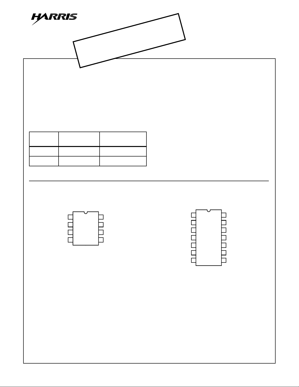
Pinouts
Electronic Switching Circuit
Description
The CA3165 is a single chip electronic switching circuit
intended primarily for ignition applications. It includes an
oscillator that is amplitude-modulated by the rotor teeth of a
distributor, a detector that develops the positive going modulation envelope, a Schmitt trigger that eliminates switching
uncertainties. Both types include two complementary high
current switched outputs for driving power transistors requiring up to 120mA. The CA3165E also includes two complementary low current outputs that incorporate internal current
limiting and a non-inverting output amplifier with uncommitted input capable of switching 27mA.
The CA3165 is supplied in the 8 lead dual-in-line plastic
package (E suffix) and in the 14 lead dual-in-line plastic
package (E1 suffix).
OSC FB
SENSE
GND
OUTPUT
CA3165 (PDIP)
TOP VIEW
1
2
3
4
8
FB_RF
7
V+
6
DET_OUT
5
INV_OUT
OSC FB
SENSE
GND
OUTPUT
+SIGNAL
INV_OUT
–SIGNAL
CA3165 (PDIP)
TOP VIEW
1
2
3
4
5
6
7
14
NC
13
FB_R
V+
12
11
NC
10
DET_OUT
AMPL_IN
9
AMPL_OUT
8
F
CAUTION: These devices are sensitive to electrostatic discharge. Users should follow proper I.C. Handling Procedures.
Copyright
© Harris Corporation 1999
10-25
File Number 1278.3

Functional Block Diagrams
CA3165
DC SUPPLY 5V - 24V
NC
54
200Ω
100K
TO POWER
TRANSISTORS
AMP
976
847Ω
OUTPUT
8
6.8KΩ
0.0047µF
FEEDBACK
RESISTOR
(6kΩ ± 0.5%)
L = 100µH
≈ 53
Q
0.01µF
13
OSCILLATOR DET
1
2
220Ω
R
1500
pF
10
0.01
REPRESENTS
ROTOR LOADING
220Ω
3.5V - 18V
12
SCHMITT
TRIGGER
OUTPUT OUTPUT
SWITCHING
3
0.01µF
OSCILLATOR
CONDITION TERMINAL 10 TERMINAL 4 TERMINAL 5 TERMINAL 6 TERMINAL 7 TERMINAL 8
Unloaded Low High High Low Low Low
Loaded High Low Low High High High
FIGURE 1. FUNCTIONAL BLOCK DIAGRAM FOR CA3165E1
FEEDBACK
RESISTOR
(6.49kΩ)
L = 100µH
≈ 53
Q
0.1µF
8
OSCILLATOR DET
1
2
220Ω
R
†
R
A
B
1500
pF
OSCILLATOR
CONDITION TERMINAL 4 TERMINAL 5 TERMINAL 6
Unloaded High High Low
Loaded Low Low High
†
REPRESENTS
ROTOR LOADING
DC SUPPLY 5V - 24V
220Ω
7
SCHMITT
TRIGGER
6
0.01
†VALUES OF R
BY CORRELATION.
A
3.5V - 18V
OUTPUT
SWITCHING
3
AND RB DETERMINED
4
200Ω
5
TO POWER
TRANSISTORS
300Ω
INVERTED
OUTPUT
FIGURE 2. FUNCTIONAL BLOCK DIAGRAM FOR CA3165E
10-26

Specifications CA3165
Absolute Maximum Ratings Thermal Information
DC Voltage (With Reference to Terminal 3)
CA3165E1
Terminals 4, 6, 8 . . . . . . . . . . . . . . . . . . . . . . . . . . . . . . . . . 24V
Terminals 5, 7, 12 . . . . . . . . . . . . . . . . . . . . . . . . . . . . . . . . 18V
Terminal 9 . . . . . . . . . . . . . . . . . . . . . . . . . . . . . . . . . . . . . .1.5V
CA3165E
Terminals 4, 5 . . . . . . . . . . . . . . . . . . . . . . . . . . . . . . . . . . . 24V
Terminal 7 . . . . . . . . . . . . . . . . . . . . . . . . . . . . . . . . . . . . . . 18V
Current (At Terminals Indicated)
CA3165E1
Terminals 4, 6 . . . . . . . . . . . . . . . . . . . . . . . . . . . . . . . . .120mA
Terminals 5, 7 . . . . . . . . . . . . . . . . . . . . . . . . . -0.1mA to 0.1mA
Terminal 8 . . . . . . . . . . . . . . . . . . . . . . . . . . . . . . . . . . . . .30mA
CA3165E
Terminals 4, 5 . . . . . . . . . . . . . . . . . . . . . . . . . . . . . . . . .120mA
CAUTION: Stresses above those listed in “Absolute Maximum Ratings” may cause permanent damage to the device. This is a stress only rating and operation
of the device at these or any other conditions above those indicated in the operational sections of this specification is not implied.
Thermal Resistance θ
JA
Plastic DIP Package 8 Lead . . . . . . . . . . . . . . . . . . . . . 150oC/W
Plastic DIP Package 14 Lead . . . . . . . . . . . . . . . . . . . . 100oC/W
Operating Temperature Range . . . . . . . . . . . . . . . . .-40oC to +85oC
Storage Temperature Range. . . . . . . . . . . . . . . . . .-65oC to +150oC
Lead Temperature. . . . . . . . . . . . . . . . . . . . . . . . . . . . . . . . . +265oC
At Distance 1/16” ±1/32” (1.59 ±0.79mm) from Case
for 10s Maximum
Device Dissipation Plastic DIP Package 8 Lead
Up to TA = +55oC. . . . . . . . . . . . . . . . . . . . . . . . . . . . . . . . 600mW
Above TA = +55oC. . . . . . . . . . . . . Derate Linearly at 6.67mW/oC
Device Dissipation Plastic DIP Package 14 Lead
Up to TA = +55oC. . . . . . . . . . . . . . . . . . . . . . . . . . . . . . . . 950mW
Above TA = +55oC. . . . . . . . . . . . . . .Derate Linearly at 10mW/oC
Electrical Specifications At T
= +25oC, V+ = 13V, Measured in the circuit of Figure 5 (CA3165E1) or Figure 6 (CA3165E)
A
CA3165E1 CA3165E
PARAMETERS SYMBOL TEST CONDITIONS
UNITSMIN TYP MAX MIN TYP MAX
Input Current at Term. (Note 1) ∆ Dwell - 18.4 - - 18.4 - mA
Spark - 17.5 - - 17.5 - mA
Output Voltage at Term. 4 V
Dwell 12.8 - - 12.8 - - V
4
Spark - - 0.5 - - 0.5 V
Output Volatge at Term. 7 V
Output Voltage at Term. 8 V
Dwell - - 1 - - - V
7
Dwell - - 0.9 - - - V
8
Portion of Spark 1.2 -----V
Oscillator Voltage at Term. 2 V
Dwell - 4.4 - - 4.4 - Vp-p
2
Spark - 0.6 - - 0.6 - Vp-p
NOTE:
1. CA3165E at Term. 7
CA3165E1 at Term. 12
∆
I7
I12
10-27

Schematic Diagrams
ALL RESISTANCES ARE IN KILOHMS
R1
0.18
Q1
1
R2
0.18R30.18R40.18
Q7
R10
0.35
Q11
R11
R12
2.9
1.8
Q14
Q16
Q2 Q3 Q4 Q5
R7
6.2
R6
0.6
Q9
Q8
R13
R8
3.3
Q12
R14
0.1
2
Q10
Q13
Q15
R9
3.3
0.18
Q6
R16
R15
1
Q17
R5
2.5
Q18
12
R17
R24
0.1
R29
0.05
CA3165
9
R18
R19
10
10
Q27
R20
6.2
4.3
Q21
Q20
Q19
R22
2.4
R25
Q24
2.1
R30
0.1
Q28 Q29
Q22 Q23
R27
1.8
R26 2.1
R
R32
31
5
2
R33
Q30
0.1
Q25
R21
2.4
R23
5.1
R28
2
Q26
R34
2
Q31
R35
5
Q38
R36
4.6
Q32
Q33
Q34
Q36
Q39 Q40
Q37
Q36
R37
4.5
8
13
3
ALL RESISTANCES ARE IN KILOHMS
Q1
1
R1
0.18R20.18
Q2
Q6
R11
0.35
Q9
R12
1.8
R10
Q38
2.9
Q21
R3
0.18
Q3 Q4 Q5
R6
R7
6.2
0.6
Q8
Q7
Q11
R13
2
R8
3.3
R13A
0.1
FIGURE 3. SCHEMATIC DIAGRAM FOR CA3165E1
7
Q10
Q13
Q12
R4
0.18
R9
3.3
R15
1
Q39
R5
0.18
Q33
R14
2.5
Q15
R1810R1910R20
R17
10
Q16
R16
0.1
Q14
R15A
0.05
Q25
Q17
R25
2.1
R31
R21
2.4
0.1
Q23
4.3
Q18
R24A
1.8
R32
2
R27
7654102
R22
2.4
Q19
Q20
R23
5.1
Q22
R24B
2
Q24
R26
2.1
R33
R34
0.1
5
Q26
2
Q28
R28
5
Q27
Q35
Q40
Q36
R29
4.6
Q29
Q41
Q30
Q32
Q37
Q31
R30
4.5
2 8 3 6 4 5
FIGURE 4. SCHEMATIC DIAGRAM FOR CA3165E
10-28

CA3165
Application Information Figure 5 and Figure 6 show the application of the CA3165 in a typical ignition system.
TERMINAL DESCRIPTIONS
TERMINAL
FUNCTIONCA3165E1 CA3165E
1 1 Oscillator Feedback Resistor, R
F
2 2 220Ω Protective Resistor To Tank Circuit
3 3 Ground
4 4 Direct Output - R7 load resistor 200Ω± 5%, and R8 to power Darlington 15Ω± 10%
5 - Direct Output - Low Current - Not Connected
6 5 Inverted High Current Output
7 - Inverted Low Current Output Through C1 (0.01µF) to D3 and R3 (100kΩ)
8 - Output Amplifier Output - Through R6 and R5 (27Ω and 820Ω to Supply)
9 - Output Amplifier Input - through R4 (6800Ω) to D3 and C5 (0.0047µF)
10 6 Detector Output - C2 to Ground (0.01µF)
11 - No Connection
12 7 Circuit Supply Voltage Through R1 (220Ω Protective Resistor) to Automotive Supply
13 8 Oscillator Feedback Resistor RF to Terminal 1
14 - No Connection
AUTOMOTIVE SUPPLY 5V - 24V
R1
C1
0.01µF
R
F
220
NC
14 13 12 11 10 9 8
H.V.
CA3165E1 TOP VIEW
NC
C2
0.01µF
R4
6.8k
R6
R7
200
R5
820
27
D2
C6
H.V.
0.0047µF
METALLIC
TRIGGER WHEEL
ONE TOOTH PER
CYLINDER
1 2 3 4 5 6 7
NC NC
C4
R2
220
L1
L1 SENSOR COIL INDUCTANCE
0.01µF
R3
100k
C3
1500pF
D3
C5
0.0047
µF
CURRENT
LIMITER
≈ 100µH UNLOADED Q ≈ 53
EXCEPT AS NOTED, RESISTOR VALUES IN OHMS
R8
15
R10
220
R11
≈ 1100
SET FOR 4 AMPERES IN R13
FIGURE 5. TYPICAL IGNITION SYSTEMS USING THE CA3165E1
10-29
R12
100
R9
6.8k
D4
D1
R13
0.18

R1
220
CA3165
820
1W
5%
200
1W
±5%
+13V
6
CA3165E
TOP
7
VIEW
8
R6
0.01µF
C6
L1 SENSOR COIL,
INDUCTANCE ≈ 100µH,
UNLOADED Q
≈ 53
C3
0.01µF
6490 ± 0.15%
METALLIC TRIGGER WHEEL,
ONE TOOTH PER CYLINDER
FIGURE 6. TYPICAL IGNITION SYSTEM USING THE CA3165E
Application Information
Figure 5 and Figure 6 show the application of the CA3165 in
a typical ignition system. The oscillator on the chip operates
at about 400kHz as determined by the tuned circuit L1, C2.
The amplitude of the oscillation is detected on the chip and
applied to a Schmitt trigger which sets the terminal voltage
as shown in the chart in Figure 1 and Figure 2 for the
unloaded condition of the oscillator. As a metallic tooth in the
rotor passes the coil L1, eddy-current losses occur which
reduce the Q of the resonant circuit and decrease the amplitude of the oscillations to a level below that of a reference in
the detector circuit. The output terminals are then switched
to states as shown in the chart in Figure 1 and Figure 2 for
the loaded condition of the oscillator. The oscillation is maintained at this lower amplitude by switching in additional feedback in the oscillator circuit. The fact that the oscillator
continues to operate at some minimum level during this
dwell period eliminates timing variations which would occur if
the oscillator had to be restarted by random noise.
Spark occurs as terminal 4 is switched from high to low. The
output amplifier clamps terminal 4 low through the regulator
during the duration of the spark.
The Dwell period represents the time that terminal 10
(CA3165E1) or terminal 6 (CA3165E) is high, terminal 4 is
low, and the coil is charged.
The value of the oscillator feedback, resistor, R
to set the dwell period. With a sintered-iron 8 f-tooth rotor, a
typical value of R
is 6500Ω for 28.5 degrees of dwell out of
F
a 45 degree cycle. For a star-type rotor and a particular coil
in a typical distributor, the feedback resistor would be larger
(typically 8800Ω) depending on clearances, coil geometry
and tooth shape.
, is selected
F
5
4
3
2
1
220
V
OUT
C2
L1
1500pF
SILVER
MICA
ALL RESISTORS 1/2 W ±5%
UNLESS OTHERWISE SPECIFIED
RESISTOR VALUES IN OHMS
For typical F-Tooth Rotor with Rod Sensor and 113µH of coil
inductance, the Q and frequency with respect to rotor position was measured for the following positions
CENTER 46 at 377kHz
SLOT 6 at 390kHz
FIRE 15 at 381kHz
(Free air Q = 55.7 at 375kHz.)
HIGH
DETECTOR
TERM 10
LOW
HIGH
TERM 4
LOW
SPARK
OSCILLATOR
OSC
LOADED
DWELL
COIL
CHARGE
FIGURE 7. TIMING SEQUENCE
DWELL
PERIOD
DWELL
OSC
UNLOADED
10-30
 Loading...