

Page 1

ATAN0046
User Guide for the Evaluation Kit ATA8510-EK1
APPLICATION NOTE
Features
• User guide for the ATA8510-EK1 evaluation kit
• Demonstrates an application with the
– RF transceiver Atmel® ATA8515 in a base station with an
Xplained PRO SAMD20 kit
– Atmel ATA8510 RF transceiver remote sensor with an
AT30TS75A temperature sensor and an optional CMM-1923
real-time clock
– Two-way RF communication
• New software version of the SAMD20 base station V2.0 is without
FreeRTOS
Description
This user guide describes an evaluation kit for industrial RF applications
having the following components:
• A base station using an
– Xplained PRO SAMD20 evaluation kit
– Xplained PRO OLED1 extension board
– Xplained PRO ATA8510/15 extension board
• Remote temperature sensor with Atmel® ATA8510 running a Flash
application
The Atmel ATA8515 is used as an RF transceiver in the base station and
runs in polling mode to detect data telegrams and displays the received
message on the OLED. The received message is also streamed to a PC
terminal program using a virtual COM port connection.
The remote sensor includes an AT30TS75A temperature sensor device and
a CMM-1923 real-time-clock device for waking up the Atmel ATA8515 RF
transceiver. The Flash application reads the temperature data from the
sensor device using a TWI bus protocol implemented in software and
broadcasts the temperature data via the RF link.
The RF application uses a 2-way communication, i.e., the transmitted RF
telegrams are acknowledged from the receiver.
Atmel-9343D-ATAN0046_Application Note-09/2016
Page 2

The RF link operates on channel 433.92MHz at an 8kBit/s data rate using FSK modulation with
Manchester encoding.
References
[1] Atmel® ATA8510/ATA8515 datasheet
[2] Atmel AT30TS75A datasheet
[3] C-MAX CMM-1923-V1.0 datasheet
[4] http://www.atmel.com
[5] http://www.iar.com
[6] Atmel ATAN0096 - ATA8510 Programmers Guide
[7] Atmel ATAN0035 - ATA583x and ATA578x Configuration Tool Guide and software
[8] Atmel ATAN0036 - ATA583x and ATA578x Flash Application Development
[9] Atmel ATA8510/ATA8515 User Manual
[10] ATA8510-EK1_Tool_Pack_V2.0.zip
Atmel User Guide for the Evaluation Kit ATA8510-EK1 [APPLICATION NOTE]
Atmel-9343D-ATAN0046_Application Note-09/2016
2
Page 3

Table of Contents
Features.......................................................................................................................... 1
Description.......................................................................................................................1
References...................................................................................................................... 2
1. Getting Started...........................................................................................................4
1.1. Kit Setup.......................................................................................................................................4
1.2. Upgrade Kit V1.x to V2.0 .............................................................................................................6
2. Data Protocol and Signal Timing............................................................................... 7
2.1. Data Protocol for Remote Sensor Telegram.................................................................................7
2.2. Data Protocol for Base Station Acknowledge...............................................................................8
2.3. Signal Timing................................................................................................................................8
3. Hardware Description................................................................................................ 9
3.1. Base Station Transceiver............................................................................................................. 9
3.2. Remote Sensor Transceiver.......................................................................................................10
4. Software Description................................................................................................13
4.1. Flash Application for the ATA8510 Remote Sensor................................................................... 13
4.2. Base Station Application for SAMD20 MCU...............................................................................14
4.3. Software Development...............................................................................................................16
4.4. EEPROM Data Settings............................................................................................................. 20
5. Revision History.......................................................................................................21
Page 4
1. Getting Started
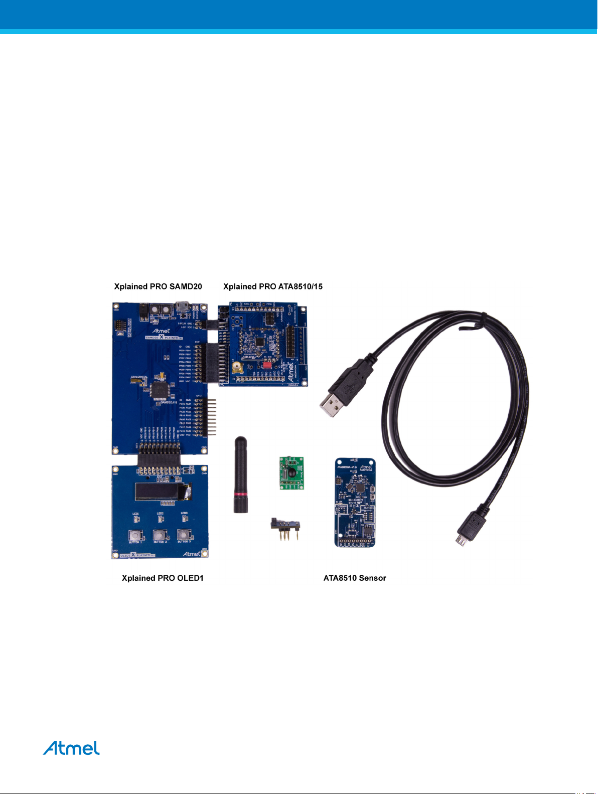
Figure 1-1 shows the components which are included in the evaluation kit. The kit includes
• A base station with
• Xplained PRO SAMD20 evaluation board
• Xplained PRO OLED1 extension board
• Xplained PRO ATA8510/15 extension board
• A remote temperature sensor with Atmel® ATA8510 [1], AT30TS75A [2], and an optional CMM-1923
[3] devices
• A mini USB cable
• A mini ISP adapter
• A 433MHz whip antenna
The remote sensor requires a CR2032 coin cell battery not included in the kit.
Figure 1-1. ATA8510-EK1 Kit Components
1.1. Kit Setup
The Xplained PRO OLED1 board is connected to the EXT3 extension header and the Xplained PRO
ATA8510/15 board is connected to the EXT1 extension header of the Xplained PRO SAMD20 board as
shown in Figure 1-2. The 433MHz whip antenna is mounted on the X4 connector of the Xplained PRO
ATA8510/15 board. These boards are powered using the USB cable connected to the debug USB
connector of the Xplained PRO SAMD20 board. The USB cable can be connected to a 5V/500mA USB
power supply for stand-alone operation. When using the virtual COM port, the USB cable is connected to
Atmel User Guide for the Evaluation Kit ATA8510-EK1 [APPLICATION NOTE]
Atmel-9343D-ATAN0046_Application Note-09/2016
4
Page 5
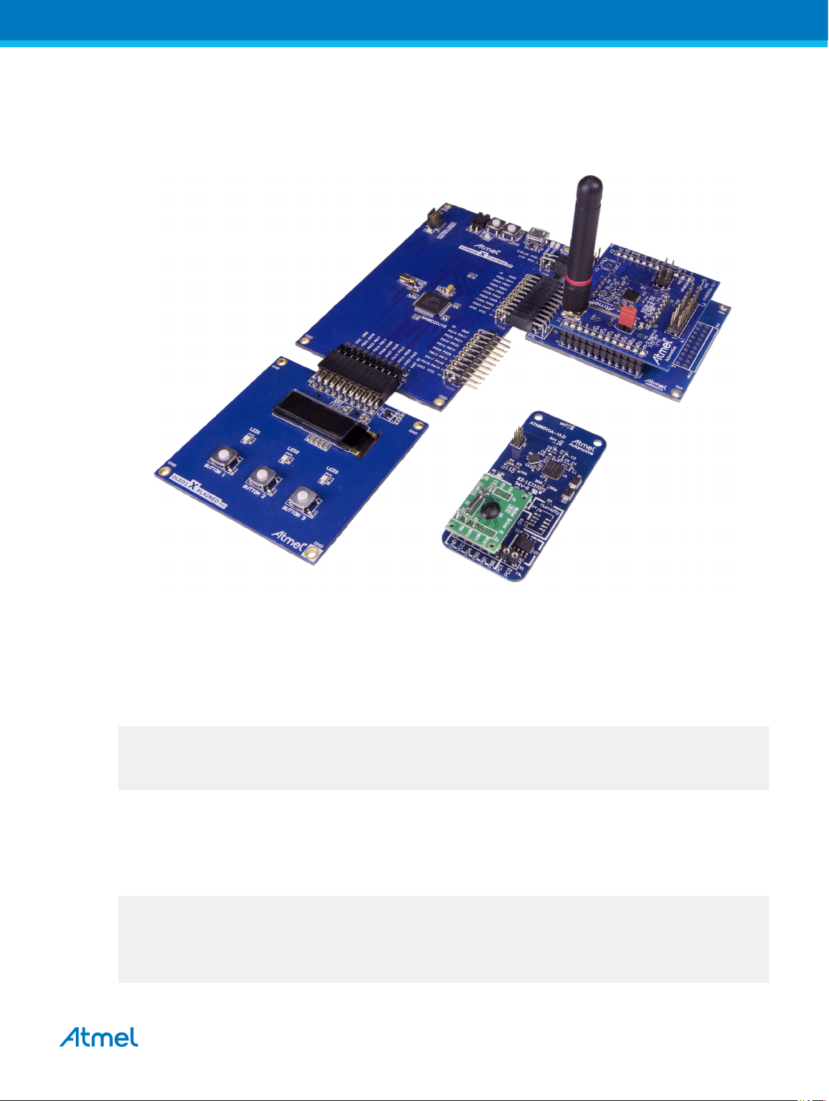
a PC's USB port, which requires previous installation of Atmel Studio 6 or 7 IDE [4]. This installation
includes all required USB drivers for operation of the Xplained PRO SAMD20 board.
Figure 1-2. ATA8510-EK1 Kit
Atmel Studio 6 or 7 can be downloaded from [4] with additional user instructions and tools.
Documentation for the Xplained PRO SAMD20 and Xplained PRO OLED1 are also available from [4].
Documentation for other components in the kit and the software is included in the tool pack zip folder [10]
available on the Atmel web site [4].
The OLED displays a welcome screen after power-up
ATA8510-EK1 Demo Kit
(c)2016 Atmel V2.0
ATA8515 V1.2
wait for RF signal ...
and waits for an RF telegram from the remote sensor. After installing the CR2032 coin cell into the remote
sensor (be sure to observe correct polarity), the sensor immediately starts sending RF telegrams at 2s
intervals when the optional RTC module is installed. The OLED shows the temperature value from the
sensor with a resolution of 1°C. The time interval between the RF signal reception in seconds and the
signal strength rssi on the base station and RSSI on the sensor is also shown:
___________________
| dt=2s rssi=221 |
| |
| T=22°C |
| RSSI=128 |
|___________________|
Atmel User Guide for the Evaluation Kit ATA8510-EK1 [APPLICATION NOTE]
Atmel-9343D-ATAN0046_Application Note-09/2016
5
Page 6

When removing the CMM-1923 real-time clock, the transmission of an RF telegram can be initiated by
pressing the S2 button (for more information, see Figure 3-2). The display can be switched to different
modes via the buttons 1-3 on the Xplained PRO OLED1 extension board (for more information, see
section Base Station Application for SAMD20 MCU).
The tool pack zip folder [10] contains the documentation and software for the kit. Extract the folder into a
directory on the PC to get the following structure:
..\Application_Notes Documentation for the kit and the application notes
for the devices
..\Documentation Device datasheets
..\Hardware Hardware documentation of the boards
..\Software Kit software and tool support extensions
..\Software\Programming_Files Device programming files in *.hex format
..\Software\IDE_Support_Files Tool support files for IAR Workbench and Atmel
Studio 6
..\Software\base Software project and sources for the Xplained PRO
kit
..\Software\base\EEPROM Configuration file for the Atmel ATA8515 device of
the base station
..\Software\base\SAMD20_XplainedPRO_SW Atmel Studio 6 or 7 project directory
..\Software\sensor Software project and sources for the remote sensor
..\Software\sensor\EEPROM Configuration file for the Atmel ATA8510 device of
..\Software\sensor\ATA5831_FLASH_IAR_2.32.0 IAR Embedded Workbench project directory
1.2. Upgrade Kit V1.x to V2.0
Any Atmel® ATA8510-EK1 kit can operate with V2.0 tool pack by programming the SAMD20 base station
with the application software from tool pack V2.0 [10]. The remote sensor need no update and will
operate with V1.x and V2.0 base station applications (see section Xplained PRO SAMD20 Base Station
for more details).
the remote
sensor
Atmel User Guide for the Evaluation Kit ATA8510-EK1 [APPLICATION NOTE]
Atmel-9343D-ATAN0046_Application Note-09/2016
6
Page 7

2. Data Protocol and Signal Timing
The remote sensor is sending a RF data telegram every 2s or when the button S2 is pressed with the
temperature data. The base station receiver is polling for this data telegram on RF channel 433.92MHz in
regular intervals of 5ms. The RF transmission and data protocol of the remote sensor and the base
station is using the following settings:
• Transmission order is MSB first for preamble and data section
• RF channel: 433.92MHz
• Data rate: 8kBit/s with FSK modulation and Manchester encoding
• Deviation: ±8kHz
Each data packet uses 2 bits before and after the data telegram to force a Manchester code violation,
which is detected by the receiver to separate the data packets and to restart the synchronization
procedure of the receiver.
2.1. Data Protocol for Remote Sensor Telegram
The remote sensor data protocol parameters are shown in Table 2-1. The Manchester encoding is using a
low-to-high transition for a '0' bit and a high-to-low transition for a '1' bit.
Table 2-1. Data Protocol
Protocol Item
Preamble 55 ‘1’ Pre-burst for wake-up and synchronization
Start bit 1 ‘0’ Start bit to indicate data payload
Data payload
Total 88 Data telegram with Ttx = 11ms at 8kBit/s
# of Data Bits Value Description
0x14 ID for no valid sensor data
8
16 Signed integer Temperature value (0.1°C resolution)
8 Checksum Checksum of ID and data payload as 2th complement
0x19 ID for low battery voltage (VCC < 2.2V)
0x64 ID for temperature data (–55 to +125°C)
The acknowledge protocol send by the remote sensor has the following data:
Table 2-2. Acknowledge Protocol
Protocol Item
Preamble 55 ‘1’ Pre-burst for wake-up and synchronization
Start bit 1 ‘0’ Start bit to indicate data payload
Data payload
Total 88 Data telegram with Ttx = 11ms at 8kBit/s
# of Data Bits Value Description
8 0x60 ID for RSSI data
16 Integer RSSI value [0-255]
8 Checksum Checksum of ID and data payload as 2th complement
Atmel User Guide for the Evaluation Kit ATA8510-EK1 [APPLICATION NOTE]
Atmel-9343D-ATAN0046_Application Note-09/2016
7
Page 8

2.2. Data Protocol for Base Station Acknowledge
TX1
Remote
sensor
11ms
1.5ms
9ms
5.5ms
5ms
polling
2s
TX1TX2RX
RX2
RX1Base TX RX1 TX
RX
The base station acknowledge protocol parameters are shown in Table 2-3. The Manchester encoding is
using a low-to-high transition for a '0' bit and a high-to-low transition for a '1' bit.
Table 2-3. Acknowledge Protocol
Protocol Item # of Data Bits Value Description
Preamble 55 ‘1’ Pre-burst for wake-up and synchronization
Start bit 1 ‘0’ Start bit to indicate data payload
Data payload
Total 72 Data telegram with Ttx = 9ms at 8kBit/s
2.3. Signal Timing
The signal timing of the data transfer is shown in Figure 2-1.
1. The remote sensor transmits a data telegram with duration of 11ms every 2s or when button S2 is
pressed (TX1). The pre-amble duration is 7ms while the data payload duration is 4ms. The remote
sensor switches then into receive mode with a timeout period of 20ms (RX).
2. The base station is polling for a valid RF signal which matches the RF channel, the data rate, the
modulation scheme and the correct data encoding every 5ms. This polling interval is chosen to
match with the length of the pre-amble. When a valid telegram is received (RX1) the base station
acknowledges this telegram (TX) and waits for an acknowledgement frame from the remote sensor
with the remote sensor signal strength data and a timeout of 90ms (RX2).
3. The remote sensor transmits the acknowledgement frame with the RSSI signal strength (TX2) and
switches then into OFF mode.
4. The base station reads the acknowledgement frame with the RSSI data (RX2), displays the result
and switches into polling mode again.
Figure 2-1. Signal Timing
8 0x60 ID for RSSI data
8 0x60 Repeated
Atmel User Guide for the Evaluation Kit ATA8510-EK1 [APPLICATION NOTE]
8
Atmel-9343D-ATAN0046_Application Note-09/2016
Page 9

3. Hardware Description
The description and documentation of the Xplained PRO SAMD20 board and the Xplained PRO OLED1
board are available within Atmel® Studio 6 or 7 on the Atmel website [4]. The hardware description of the
Xplained PRO ATA8510/15 extension board and the remote sensor are included in the tool pack zip folder
[10]. The base station is powered by the USB cable whereas the remote sensor uses a CR2032 coin cell
battery.
3.1. Base Station Transceiver
The Atmel® ATA8515 base station transceiver is mounted on an adapter board as shown in Figure 3-1.
This adapter board is plugged onto the Xplained PRO ATA8510/15 extension board which includes the
LEDs 1-4. The adapter board has a programming adapter XISP1 which is used for programming the
EEPROM configuration data into the device. This extension board is connected to the EXT1 and PWR
header of the Xplained PRO SAMD20 board. The extension board has two additional connectors, X6 for
supplying the kit with 5V and X7 to access the kit’s internal 3V supply voltage.
Figure 3-1. Base Station Transceiver Board
The connector pins of the Xplained Pro ATA8510/15 extension board are summarized in the following
tables Table 3-1, Table 3-2, Table 3-3 and Table 3-4.
Table 3-1. Connector X3
Function Pin Pin Function
ID_data 1 2 GND
-- 3 4 --
NPWRON1 (PB06) 5 6 NRESET (PB07)
LED3 (PB02) 7 8 LED4 (PB03)
EVENT (PB04) 9 10 --
-- 11 12 --
Atmel User Guide for the Evaluation Kit ATA8510-EK1 [APPLICATION NOTE]
Atmel-9343D-ATAN0046_Application Note-09/2016
9
Page 10

Function Pin Pin Function
LED1 (PB09) 13 14 LED2 (PB08)
NSS 15 16 MOSI (PA06)
MISO (PA04) 17 18 SCK (PA07)
GND 19 20 VCC
Table 3-2. Connector X5
Function Pin Pin Function
5V in 1 2 GND
-- 3 4 --
Table 3-3. Connector X6
Function Pin Pin Function
5V in 1 2 GND
Table 3-4. Connector X7
Function Pin Pin Function
VCC 1 2 GND
3.2. Remote Sensor Transceiver
The Atmel® ATA8510 remote sensor transceiver is placed on a key fob board as shown in Figure 3-2.
This remote sensor is powered by a CR2032 coin cell battery (not included) mounted on the bottom of the
board. The board contains the real-time clock CMM-1923 [3] attached to the connector X1 and the
AT30TS75A [2] temperature sensor. The S1 and S2 buttons are placed on the board with the S1 button
not used in this application and the S2 button used for initiating data telegram transmission. The LED
flashes during a temperature measurement before transmitting the RF data telegram. The mini ISP
header is used for Flash and EEPROM programming and for Flash application debugging of the Atmel
ATA8510 (see [8] for more details about Flash application development).
Atmel User Guide for the Evaluation Kit ATA8510-EK1 [APPLICATION NOTE]
Atmel-9343D-ATAN0046_Application Note-09/2016
10
Page 11

Figure 3-2. Remote Sensor Transceiver Board
0 10
9.40000
tx mode
Off mode
measure mode and LED
measure mode only
i [mA]
t [ms]
0.53500
0.06500
20
30 40 50 60 70 80
0.00035
The current consumption profile over time is shown in Figure 3-3. During the temperature measurement
period of 40ms, the LED is switched on in parallel, increasing current consumption. Figure 3-3 shows
current consumption for the measurement period with and without LED. The RF telegram transmission
takes about 11ms at a power level of 6dBm, resulting in current consumption of about 9.4mA. In OFF
mode the temperature sensor is switched off and the resulting current is indicated by the Atmel ATA8510
transceiver and the CMM-1923 RTC current consumption. This OFF mode current is highly dependent on
ambient temperature shown in the datasheets [1] and [3]. Figure 3-3 indicates current consumption
measured at a room temperature of 24°C.
Figure 3-3. Remote Sensor Current Consumption at 24°C
Atmel User Guide for the Evaluation Kit ATA8510-EK1 [APPLICATION NOTE]
Atmel-9343D-ATAN0046_Application Note-09/2016
11
Page 12

Table 3-5 summarizes battery life for a CR2032 and CR2450 coin cell without using the LED during
temperature measurement at 20°C. It is assumed that the battery voltage drops from the initial value of
3V down to 2V by the end of battery service. The self discharge is defined by the manufacturer with
typically 1% per year at an ambient temperature of 20°C. The battery life for this application primarily
depends on the measurement interval Ts, which defines the duration of the OFF mode whereas
measurement and transmit mode have fixed durations.
Table 3-5. Battery Life at 20°C
Interval Ts Mean Current Battery Lifetime (Days/Years)
(s) (mA) CR2032 (230mAh) CR2450 (560mAh)
Days Years Days Years
2 0.053 180 0.5 437 1.2
5 0.022 445 1.2 1083 3.0
10 0.011 875 2.4 2131 5.8
20 0.006 1696 4.6 4130 11.3
50 0.002 3880 10.6 9448 25.9
Atmel User Guide for the Evaluation Kit ATA8510-EK1 [APPLICATION NOTE]
Atmel-9343D-ATAN0046_Application Note-09/2016
12
Page 13

4. Software Description
check wake-up source
switch sensor power and LED on
Initialisation
Off mode
Off mode
perform temperature
measurement [40ms]
Measurement
switch off LED and
transmit data telegram [11ms]
Low battery
voltage?
Perform 2-way RF communication
[200ms]
Wait
transmit error telegram [11ms]
Transmission
Wake-up
source?
yes
applied
released
no
The demo application uses the following programs:
1. A Flash application with EEPROM settings for the Atmel® ATA8510 remote sensor
2. A SAMD20 application with EEPROM settings for the Atmel ATA8515 receiver
The following section describes each program flow. The IAR embedded workbench for AVR® [5] is used
together with the JTAGICE3 debug tool for Flash application development of the remote sensor. Atmel
Studio 6 or 7 [4] is used together with the debug tool included on the Xplained PRO SAMD20 board for
SAMD20 application development.
The source code for all applications is available within the tool pack distribution [10].
4.1. Flash Application for the ATA8510 Remote Sensor
The program flow for the remote sensor application is illustrated in Figure 4-1. The initial state of the
device is the OFF mode. The real-time clock of the remote sensor wakes up the transceiver every 2s and
switches the device to active mode. The temperature sensor is powered up and read out followed by the
transmission of the data telegram. During transmission of this data telegram the supply voltage level is
checked and if this is below 2.2V, an error message is transmitted after a delay of 200ms. The device
then enters the OFF mode again until the next wake-up by the RTC (or by pressing the S2 button).
Figure 4-1. Flash Application for the Atmel ATA8510 Remote Sensor
Atmel User Guide for the Evaluation Kit ATA8510-EK1 [APPLICATION NOTE]
13
Atmel-9343D-ATAN0046_Application Note-09/2016
Page 14

4.2. Base Station Application for SAMD20 MCU
Initialisation
IO, USART, SPI, ATA8515,
OLED, LED
Reset
Display temperature and
RSSI data
yes
yes
yes
no
no
RF event?
Set ATA8515 in Polling mode
Enable timer
Show COM port settings
Show RF statistics
Read RX and RSSI buffer
Send Acknowledge
Wait for Sensor answer
no
no
no
Button 1
pressed?
Button 2
pressed?
Button 3
pressed?
Data correct?
Show RF settings
yes
yes
The program flow for the SAMD20 application is illustrated in Figure 4-2. This application performs at the
start an initialization of the peripherals, the LEDs and the OLED display. The ATA8515 RF transceiver is
switched into RF polling mode to check for the reception of a valid remote sensor signal. In addition a
timer is initialized for time measurements between RF signal transmissions. The software is then entering
an infinite loop to check for an RF event signal from the RF transceiver or for a button press of one of the
buttons on the OLED1 extension board. A button press will show the corresponding information on the
OLED display as shown in Figure 4-2. When a RF event is detected the RX and RSSI buffer are read and
the RX data are checked with their checksum to be a valid data stream. If the data is not valid the polling
mode is enabled again to check for another RF signal. If the data is valid an acknowledge signal is send
followed by waiting for an RF answer telegram. Finally the received temperature and RSSI data are
shown on the OLED display. All text shown on the OLED display is also streamed via the USART
peripheral and can be shown on a PC Terminal program connected to the virtual COM port of the
SAMD20 kit.
Figure 4-2. Flash Application for SAMD20 MCU
Atmel User Guide for the Evaluation Kit ATA8510-EK1 [APPLICATION NOTE]
Atmel-9343D-ATAN0046_Application Note-09/2016
14
Page 15

The OLED display will show the following text information:
Start page:
shows the welcome message with software and transceiver firmware version information and awaits a
remote sensor signal.
ATA8510-EK1 Demo Kit
(c) Atmel 2016 V2.0
ATA8515 V1.2
wait for RF signal ...
Button 1 menu:
shows parameters used in the RF telegram.
RF-Channel 433.92MHz
Data rate 8kBit/s
FSK deviation +/-8kHz
Manchester coding
Button 2 menu:
shows parameters used for the virtual COM port. These parameters have to be set in the PC terminal
application to receive the text strings.
COM port settings
baudrate 38.4kBaud
8 data + 1 stop bit
no parity, no handshake
Button 3 menu:
shows parameters used for the virtual COM port. These parameters have to be set in the PC
terminal application. To receive the text strings.
Receiver statistics:
valid# 3062
error# 15
total# 3099
Measurement results:
The measurement display shows the time interval dt between two consecutive RF telegram receptions
together with the RSSI value for the RF signal strength at the base station and at the Remote sensor. The
temperature at the sensor is shown with a resolution of 1°C.
___________________
| dt=2s rssi=221 |
| |
| T=22°C |
| RSSI=128 |
|___________________|
In case of an error the following error messages are displayed:
This message is shown when the received data telegram is corrupted or when the temperature sensor is
broken or not present.
!!!!!!!!!!!!!!!!!!!!!!
Sensor error:
Invalid sensor data!
!!!!!!!!!!!!!!!!!!!!!!
Atmel User Guide for the Evaluation Kit ATA8510-EK1 [APPLICATION NOTE]
Atmel-9343D-ATAN0046_Application Note-09/2016
15
Page 16

This message is shown when the sensor battery has a voltage below 2.2V and needs to be replaced.
!!!!!!!!!!!!!!!!!!!!!!
Sensor error:
Low battery voltage!
!!!!!!!!!!!!!!!!!!!!!!
This message is shown when a wrong acknowledge telegram was received.
::::::::::::::::::::::
RF telegram error:
Wrong ACK telegram!
::::::::::::::::::::::
This message is shown when no RF acknowledge telegram was received.
::::::::::::::::::::::
RF channel error:
No RF ACK telegram!
::::::::::::::::::::::
This message is shown when the RF acknowledgement from the base station could not be send.
::::::::::::::::::::::
RF channel error:
RF TX telegram err!
::::::::::::::::::::::
This message is shown when the RF receiver is detecting a signal on another RF channel (this must be
enabled in the EEPROM configuration of the receiver).
::::::::::::::::::::::
RF channel error:
Wrong RF telegram!
::::::::::::::::::::::
4.3. Software Development
Atmel® Studio 6 or 7 is required for base station software development and can be downloaded from the
Atmel website [4]. In addition, the tool pack [10] with software and documentation is required. IAR
Embedded Workbench for AVR [5] and the JTAGICE3 AVR® debug tool [4] are required for remote sensor
software development.
4.3.1. Xplained PRO SAMD20 Base Station
For the software development of the base station the project file is located in the extracted folder in the
subdirectory
..\Software\base\SAMD20_XplainedPRO_SW Atmel Studio 6 or 7 project directory
After the installation of Atmel® Studio 6 or 7 the USB driver will be installed automatically when
connecting the Xplained Pro SAMD20 board for the first time. When opening Atmel Studio you will see
the landing page of this kit were you can obtain the documentation and sample projects. The OLED
display will show the welcome screen and wait for a RF telegram from the remote sensor. After attaching
the battery to the remote sensor the RF telegram will be immediately transmitted and is repeated every
2 seconds with an update on the temperature, RF telegram interval and RSSI signal strength parameter
(if the optional real time clock is installed on the sensor otherwise the button S2 on the remote sensor can
be pressed to transmit a RF telegram). You can also view the received information when opening a PC
terminal application and selecting the COM port of the XplainedPRO board with a baudrate of 38.4kBaud,
8 data bit, 1 stop bit no parity and no handshake selected.
Atmel User Guide for the Evaluation Kit ATA8510-EK1 [APPLICATION NOTE]
Atmel-9343D-ATAN0046_Application Note-09/2016
16
Page 17

To start evaluating the software, you can select the main.c file from the solution window inside Atmel
Studio 6 or 7 (see Figure 4-3):
The implementation can be analyzed and debugged together with the program flow shown in Figure 4-2.
Additional documentation regarding the other ASF functions can be obtained within Atmel Studio 6 or 7
Help.
Figure 4-3. Base Software
The debugging of the application is performed within Atmel Studio 6 or 7 together with the Xplained PRO
SAMD20 board. This board includes an embedded debugger which is controlled by Atmel Studio.
4.3.2. Remote Sensor
IAR Embedded Workbench for AVR® is required for remote sensor software development [5]. The project
file is located in the extracted subfolder:
..\Software\sensor\ATA5831_FLASH_IAR_2.32.0 IAR Embedded Workbench project directory
After opening the IAR project Remote_sensor.eww file, the following workspace window is available (see
Figure 4-4).
Figure 4-4. Remote Sensor Software
Select the following files from the workspace window to start evaluating the software:
FlashRomAppl.c Main() program start with initialization and activation of the application loop
KeyFobSensor_flash_temp.c Application functions called within the main() function
Atmel User Guide for the Evaluation Kit ATA8510-EK1 [APPLICATION NOTE]
Atmel-9343D-ATAN0046_Application Note-09/2016
17
Page 18

The implementation can be analyzed, compiled, and linked together with the program flow shown in
Figure 4-1.
Debugging of the application is currently not supported within IAR Embedded Workbench using the AVR
debug tool JTAGICE3. Atmel Studio 6 or 7 has to be used instead. Once the program is compiled and
linked within IAR Workbench, the file fwFLASH.d90 has to be opened within Atmel Studio 6 or 7 as
shown in Figure 4-5. To select the right directory paths use the <...> buttons to locate the *.d90 file and for
the ‘Location’.
Figure 4-5. Debugging the Remote Sensor Software
After selecting Next>, the device has to be selected. The Atmel ATA8510 device is not currently listed and
the ATA5831 device (the similar automotive device) has to be selected instead as shown in Figure 4-6.
Selecting “Finish” shows the project window and after selecting the debug tool, the debugging can be
performed much the way you would when using the base software.
Atmel User Guide for the Evaluation Kit ATA8510-EK1 [APPLICATION NOTE]
Atmel-9343D-ATAN0046_Application Note-09/2016
18
Page 19

Figure 4-6. Device Selection for Debugging
The Atmel ATA8510 device uses the debugWire interface for the debug connection (described in the user
manual [9]). This connection uses the reset line on pin PC0 of the device and must be enabled within ISP
programming mode. If debugWire mode is enabled, the ISP mode is not available and vice versa. Select
“Disable debugWire connection” within the “Debug” menu to return to ISP mode. The 6-pin ISP connector
is used as a connection to the debugger and it is recommended to connect only the VCC, GND and reset
signal when debugging, leaving the SPI signals open for the application. This is important because the
TWI driver software uses the PB1 pin as an SCL line shared with the ISP and SPI peripheral. Additional
information on how to perform development and debugging with the Atmel ATA8510 device is provided in
[6] and [8]. This application note describes development for the Atmel ATA5831 device which, in terms of
Flash development, is similar to the Atmel ATA8510 device.
4.3.3. Re-programming of the Devices
The tool pack [10] includes the original programming files to re-program all devices in the kit.
1. For re-programming of the SAMD20 device select the device ATSAMD20J18 in the device
programming tool of Atmel® Studio 6 and the file SAMD20_Flash.hex for the flash memory.
2. For re-programming of the Atmel ATA8515 device on the XplainedPRO ATA8510/15 extension
board disconnect the board and apply an external 3V power supply to the connector X7. Connect
pin 5 of connector X3 to GND (to prevent the device from entering the OFF mode) and select the
device ATA5833 in the device programming tool and ensure that the ISP clock is set < 64kHz.
Select the file Base_Station_EEPROM.hex for the EEPROM memory. For the fuse settings the
fuses SPIEN and EESAVE should be set.
3. For re-programming of the Atmel ATA8510 device of the remote sensor attach the mini-ISP
connector to the connector ISP and the debug tool and insert the CR2032 battery or apply an
external 3V power supply to the mini ISP connector. Remove the CMM1923 rtc module and
connect pin VCC to PB4 on connector X1 (to prevent the device from entering the OFF mode).
Select the device ATA5831 in the device programming tool and ensure that the ISP clock is set <
64kHz. Select the file Remote_Sensor_Flash.hex for the flash memory and the file
Remote_Sensor_EEPROM.hex for the EEPROM memory. For the fuse settings the fuses SPIEN
and EESAVE should be set.
Atmel User Guide for the Evaluation Kit ATA8510-EK1 [APPLICATION NOTE]
19
Atmel-9343D-ATAN0046_Application Note-09/2016
Page 20

4.4. EEPROM Data Settings
The EEPROM of the Atmel® ATA8510 and ATA8515 device includes the configuration of the device and
the settings for the RF protocol. This EEPROM must be programmed before running application software
either as an embedded Flash application or as a host application using the SPI communication link. The
Atmel ATA5831 device has to be selected instead of the Atmel ATA8510 or ATA8515 within the
programming dialog of Atmel Studio 6. Make sure that the ISP signals are available for the programmer
only and that the device is not in OFF mode by pulling an NPWRONx pin to GND level, i.e., connect the
PC1 pin to GND.
A Java GUI tool is used for generating the EEPROM programming file in HEX format (see [7] for the tool
software and user guide, which is not included in the tool pack [10]). This tool can save all settings in an
xml file and handling is described in the user guide [7] and the settings in the user manual [9].
The tool pack includes two subdirectories which contains the xml and HEX files for the base and the
remote sensor:
..\Software\base\EEPROM Configuration file for the Atmel ATA8515 base station device
..\Software\sensor\EEPROM Configuration file for the Atmel ATA8510 remote sensor device
Only service 0 with channel 0 is used for the RF telegram. All other service settings can be ignored. For
the base station the polling is defined in the polling tab of the GUI.
Atmel User Guide for the Evaluation Kit ATA8510-EK1 [APPLICATION NOTE]
Atmel-9343D-ATAN0046_Application Note-09/2016
20
Page 21

5. Revision History
Please note that the following page numbers referred to in this section refer to the specific revision
mentioned, not to this document.
Revision No. History
• Features: new bullet point added
• Reference no. [10] on page 2 changed
• Chapter 1: "Getting Started" changed and new heading "Kit Setup" added
after figure 1-1 and the following text
• in new Chapter 1.1 "Kit Setup" text changed
• new Chapter 1.2: "Upgrade Kit V1.x to V2.0" added
• Chapter 2.3: text in point 2 changed and figure 2-1 changed
9343D-09/16
• Chapter 3: "Hardware Description" text changed
• Chapter 3.1: new text and tables added after figure 3-1
• Chapter 4: text changed
• Chapter 4.2: completely changed
• Chapter 4.3: text changed
• Chapter 4.3.1: completely changed
• Chapter 4.3.2: text changed
• Chapter 4.3.3: text changed
Atmel User Guide for the Evaluation Kit ATA8510-EK1 [APPLICATION NOTE]
Atmel-9343D-ATAN0046_Application Note-09/2016
21
Page 22

Atmel Corporation 1600 Technology Drive, San Jose, CA 95110 USA T: (+1)(408) 441.0311 F: (+1)(408) 436.4200 | www.atmel.com
©
2016 Atmel Corporation. / Rev.: Atmel-9343D-ATAN0046_Application Note-09/2016
Atmel®, Atmel logo and combinations thereof, Enabling Unlimited Possibilities®, and others are registered trademarks or trademarks of Atmel Corporation in U.S. and
other countries. Other terms and product names may be trademarks of others.
DISCLAIMER: The information in this document is provided in connection with Atmel products. No license, express or implied, by estoppel or otherwise, to any
intellectual property right is granted by this document or in connection with the sale of Atmel products. EXCEPT AS SET FORTH IN THE ATMEL TERMS AND
CONDITIONS OF SALES LOCATED ON THE ATMEL WEBSITE, ATMEL ASSUMES NO LIABILITY WHATSOEVER AND DISCLAIMS ANY EXPRESS, IMPLIED
OR STATUTORY WARRANTY RELATING TO ITS PRODUCTS INCLUDING, BUT NOT LIMITED TO, THE IMPLIED WARRANTY OF MERCHANTABILITY,
FITNESS FOR A PARTICULAR PURPOSE, OR NON-INFRINGEMENT. IN NO EVENT SHALL ATMEL BE LIABLE FOR ANY DIRECT, INDIRECT,
CONSEQUENTIAL, PUNITIVE, SPECIAL OR INCIDENTAL DAMAGES (INCLUDING, WITHOUT LIMITATION, DAMAGES FOR LOSS AND PROFITS, BUSINESS
INTERRUPTION, OR LOSS OF INFORMATION) ARISING OUT OF THE USE OR INABILITY TO USE THIS DOCUMENT, EVEN IF ATMEL HAS BEEN ADVISED
OF THE POSSIBILITY OF SUCH DAMAGES. Atmel makes no representations or warranties with respect to the accuracy or completeness of the contents of this
document and reserves the right to make changes to specifications and products descriptions at any time without notice. Atmel does not make any commitment to
update the information contained herein. Unless specifically provided otherwise, Atmel products are not suitable for, and shall not be used in, automotive
applications. Atmel products are not intended, authorized, or warranted for use as components in applications intended to support or sustain life.
SAFETY-CRITICAL, MILITARY, AND AUTOMOTIVE APPLICATIONS DISCLAIMER: Atmel products are not designed for and will not be used in connection with any
applications where the failure of such products would reasonably be expected to result in significant personal injury or death (“Safety-Critical Applications”) without
an Atmel officer's specific written consent. Safety-Critical Applications include, without limitation, life support devices and systems, equipment or systems for the
operation of nuclear facilities and weapons systems. Atmel products are not designed nor intended for use in military or aerospace applications or environments
unless specifically designated by Atmel as military-grade. Atmel products are not designed nor intended for use in automotive applications unless specifically
designated by Atmel as automotive-grade.
 Loading...