

Page 1
8936
INTERIM DATA SHEET
VOICE COIL MOTOR DRIVER
(Subject to change without notice)
March 16, 1993
8936
Data Sheet
26300.6
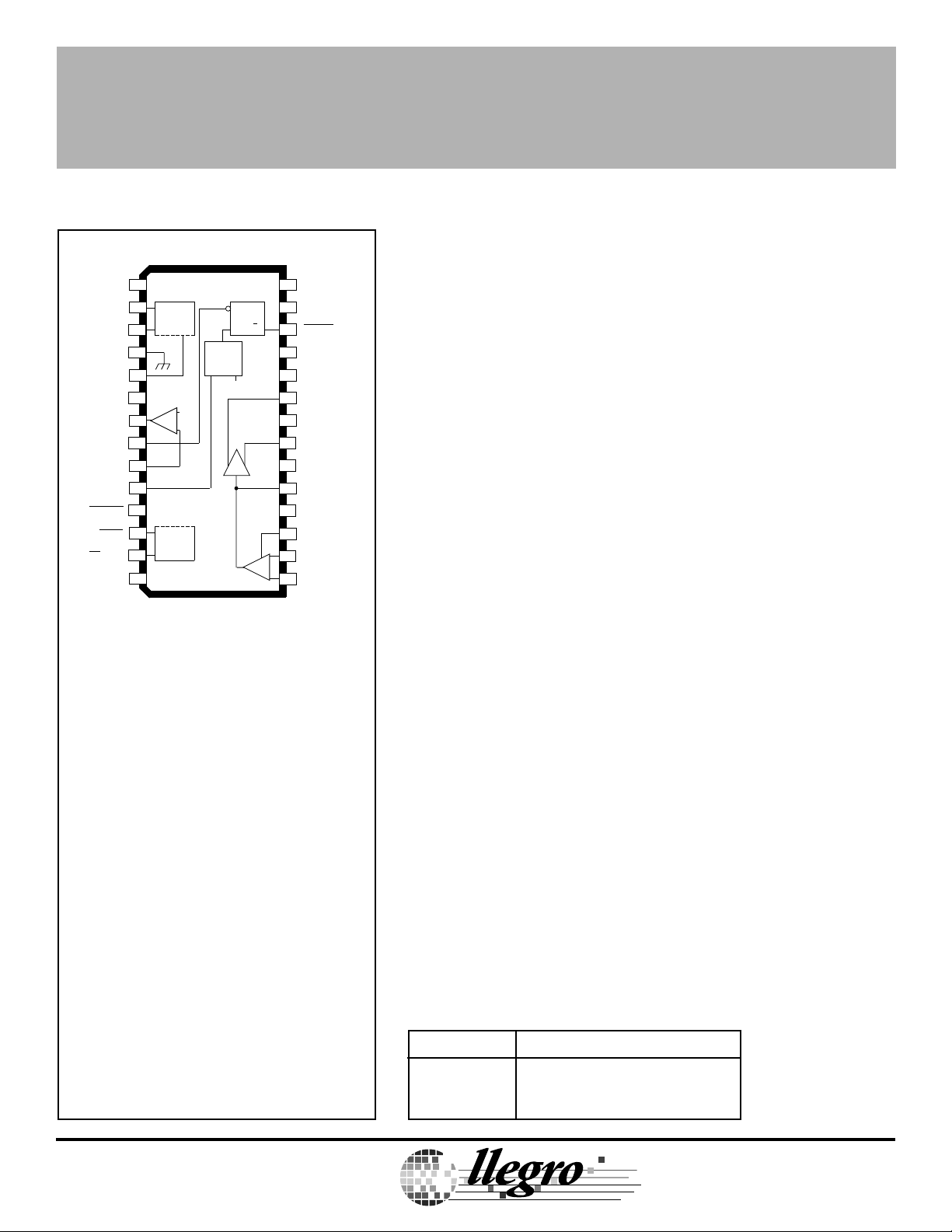
VOICE COIL MOTOR DRIVER
A8936CLW
1
RET REF
V
2
V
BEMF
GROUND
UV
R
OUT P
OUT
EN VEL FLT
IN
VEL
RETRACT
FAULT
MP
RESET
SIGNAL
SUPPLY
FLT
PROTECT
CIRCUIT
3
4
5
SET
6
V
+
PROTECT
CIRCUIT
V
CC
REF
–
7
8
9
N
10
IN
11
12
13
14 15
WINDOW
COMP.
V
REF
R
Q
S
ABSOLUTE MAXIMUM RATINGS
Supply Voltages, VCC and VDD........... 6.0 V
Output Current, I
(continuous) ........................... ±500 mA
Analog Input Voltage Range,
V
................................... -0.3 V to V
IN
Logic Input Voltage Range,
V
............................... -0.3 V to +6.0 V
IN
Package Power Dissipation,
P
........................................ See Graph
D
(peak) .......... ±600 mA
OUT
RET SET
28
27
V
SENS
VEL FLT
26
V
25
SENS FB
24
SGND
N
OUT
23
P
LOAD
22
V
DD
SUPPLY
21
OUT
N
SGND
20
P
ACT
19
FB
18
PWR OFF
H GAIN
17
16
REFERENCE
+
–
ACT
Dwg. PP-046A
CC
Providing control and drive of the voice coil motor used for head
positioning in 5 V disk drive applications, the A8936C— is a full-bridge
driver which can be configured so that its output current is a direct
function of an externally applied control voltage or current. This linear
current control function is supplemented by additional circuitry to
protect the heads and the data disk during system failure or normal
system shutdown. An under- or over-velocity sense disables the
system in a controlled sequence if a fault condition occurs.
The two ±500 mA MOS driver outputs provide very low saturation
voltage and minimal power dissipation. Additional headroom is
achieved by the sense-FET structure eliminating the need for an
external current-sense resistor. Thermal protection and under-voltage
lockout disables the system in a controlled sequence if a fault condition occurs.
FEATURES
■ Over-Velocity Fault Function
■ Lossless Current Sensing
■ Zero Deadband
■ High Transconductance Bandwidth
■ User-Adjustable Transconductance Gain
■ Digital Transconductance Gain Switch (4:1 Ratio)
■ 5 Volt Monitor with Selectable UV Trip Point
■ Retract Circuitry Functional to 0 Volts
■ Chip Enable/Sleep Mode Function
■ 1 V at 500 mA Output Saturation Voltage
■ Internal Thermal Shutdown Circuitry
Operating Temperature Range,
T
.....................................0°C to +70°C
A
Junction Temperature, T
.............. +150°C
J
†
Storage Temperature Range,
T
................................-55°C to +150°C
S
DISCONTINUED PRODUCT
† Fault conditions that produce excessive
junction temperature will activate device thermal
shutdown circuitry. These conditions can be
tolerated, but should be avoided.
Output current rating may be restricted to a value
— FOR REFERENCE ONLY
determined by system concerns and factors.
These include: system duty cycle and timing,
ambient temperature, and use of any heatsinking
and/or forced cooling. For reliable operation the
specified maximum junction temperature should
not be exceeded.
Always order by complete part number:
Part Number Package
A8936CJT 64-Lead Thin Quad Flatpack
A8936CLW 28-Lead SOIC
A
TM
TM
MicroSystems, Inc.
Page 2
8936
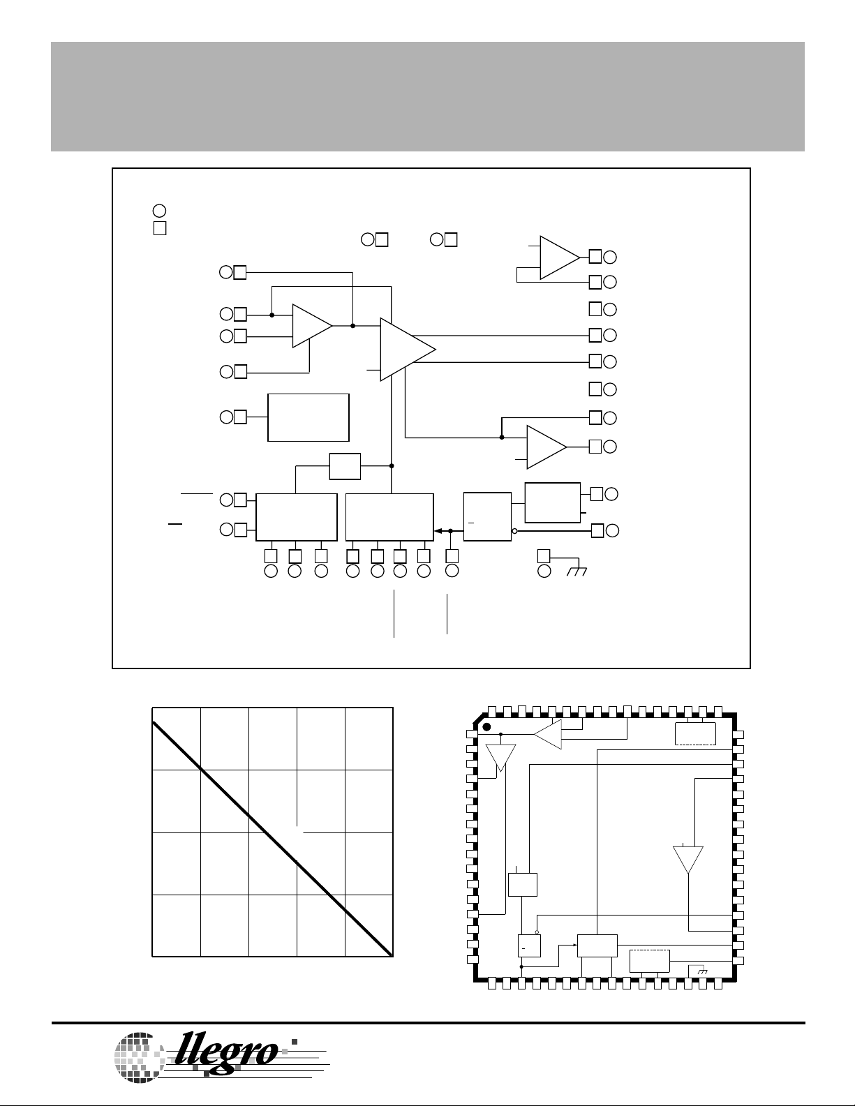
VOICE COIL MOTOR DRIVER
FUNCTIONAL BLOCK DIAGRAM
= 'LW' WIDE-BODY SOIC
= 'JT' THIN QUAD FLATPACK
19
FB
1
15
55
16
58
60
17
18
62
12
50
13
51
ACT
ACT
REFERENCE
H GAIN
PWR OFF
FAULT
MP
RESET
SIGNAL
SUPPLY
14 22
V
CC
I
SENSE +
ERROR
AMP
–
2 V
+
–
+
POWER
CONTROL
LOGIC
TSD
PROTECTION
CIRCUITRY
33
28 27 23 25 47 34
53 2 281 611 4
SET
BEMF
UV
V
V
FLT
RETRACT
CONTROL
RET REF
RET SET
POWER
AMP
I
SENSE –
RETRACT
LOAD
SUPPLY
853
V
DD
19
26
OUT P
R
V
REF
CURRENT-SENSE
AMP
V
REF
S
Q
R
Q
VEL FLT
+
–
–
+
WINDOW
COMP.
30
GROUND
35
45
2
13
4
15
16
21
46
V
REF
36
7
OUT
9
IN
20
SGND
23
OUT
21
OUT
24
SGND
25
V
27
V
10
VEL
8
EN VEL FLT
Dwg. FP-030A
N
P
P
N
N
SENS FB
SENS
IN
2.0
1.5
FREE AIR,
R = 66°C/W
θJA
1.0
0.5
0
25
ALLOWABLE PACKAGE POWER DISSIPATION IN WATTS
A
50 75 100 125 150
AMBIENT TEMPERATURE IN °C
Dwg. GP-034
TM
TM
MicroSystems, Inc.
115 Northeast Cutoff, Box 15036
115 Northeast Cutoff, Box 15036
Worcester, Massachusetts 01615-0036 (508) 853-5000
Worcester, Massachusetts 01615-0036 (508) 853-5000
Copyright © 1992, 1993, Allegro MicroSystems, Inc.
A8936CJT
V
PROTECT.
CIRCUIT
CC
PROTECT.
CIRCUIT
V
REF
+ —
Dwg. PP-052-1
+
—
V
DD
V
REF
WINDOW
COMP.
S R
Q
RETRACT
CONTROL
Page 3
8936
VOICE COIL MOTOR DRIVER
ELECTRICAL CHARACTERISTICS at T
= +25°C, VCC = VDD = 5.0 V, V
A
= VIN= 2.0 V,
REF
Load = 150 µH/3.5 Ω (unless otherwise noted).
Limits
Characteristic Symbol Test Conditions Min. Typ. Max. Units
Error Amplifier
Input Offset Voltage V
Current Gain A
Current Gain Linearity E
Reference Voltage Range V
IO
iH
A
iL
L(adj)
REF
Current-Sense Amplifier
Voltage Gain A
Input Offset Voltage V
VD
iO
Output Drivers
Output Saturation Voltage V
DS(SAT)
(Source + Sink)
Retract Output Saturation Voltage V
Output Current I
DS(SAT)
O
Full Power Bandwidth BW -3 dB 1.0 —— kHz
Window Comparator
Lower Trip Point VEL
Upper Trip Point VEL
IN
IN
Uncommitted Op Amp
Voltage Gain A
VS
Unity Gain Bandwidth BW — 1.0 — MHz
Max. Load Capacitance C
LOAD
Slew Rate SR — 4.2 — V/µs
Output Voltage V
Max. Output Current I
Input Offset Voltage V
O
O
IO
I
= 0 mA ——50 mV
LOAD
H GAIN ≥ 3.5 V 7200 8000 8800 —
H GAIN ≤ 0.7 V 1800 2000 2200 —
I
= 5 mA to 500 mA, Ai = A
OUT
= 5 mA to 500 mA, Ai = A
I
OUT
iL
iH
——±10 %
——±10 %
1.5 — 2.5 V
Rs = R
gm
I
= 0 mA, Ai = A
LOAD
I
= 100 mA — 0.25 — V
LOAD
I
= 500 mA — 1.5 — V
LOAD
I
≤ 150 mA ——1.0 V
OUT
iL
— 1.0 ——
——±25 mV
Pulse Test, ±600 mA Limited ——±500 mA
1.12 1.25 1.38 V
2.47 2.75 3.03 V
— 91 — dB
40 —— pF
VIO = 100 mV 2.5 — 3.5 V
— ±250 — µA
——±10 mV
Negative current is defined as coming out of (sourcing) the specified device terminal.
Typical Data is for design information only.
Continued next page …
Page 4

8936
VOICE COIL MOTOR DRIVER
ELECTRICAL CHARACTERISTICS at T
= +25°C, VCC = VDD = 5.0 V, V
A
= VIN= 2.0 V,
REF
Load = 150 µH/3.5 Ω (unless otherwise noted).
Limits
Characteristic Symbol Test Conditions Min. Typ. Max. Units
Miscellaneous
Under-Voltage Lockout Voltage V
Fault Logic Output V
Power-On Reset V
Total Supply Current I
Logic Input Voltage V
Thermal Shutdown Temperature T
Thermal Shutdown Hysteresis ∆T
Negative current is defined as coming out of (sourcing) the specified device terminal.
Typical Data is for design information only.
CC
FAULT
I
FAULT
MPRESET
+ I
CC
DD
IN(0)
V
IN(1)
J
J
VCC = V
V
V
V
V
V
Outputs Balanced, No Load ——10 mA
Sleep Mode, PWR OFF = V
DD
≥ 3.5 V ——500 mV
RETRACT
≤ 0.7 V 4.5 —— V
RETRACT
= 2.25 V 20 —— µA
FLT
≥ 3.5 V 4.5 —— V
RETRACT
RETRACT
≤ 0.7 V, I
= 1.5 mA ——800 mV
MPRESET
CC
3.9 4.2 4.35 V
——2.0 mA
——0.7 V
3.5 —— V
— 165 — °C
— 20 — °C
A
TM
TM
MicroSystems, Inc.
115 Northeast Cutoff, Box 15036
Worcester, Massachusetts 01615-0036 (508) 853-5000
Page 5

8936
VOICE COIL MOTOR DRIVER
TERMINAL FUNCTIONS
"JT" Term."LW" Term. Term. Name Function
25 1 RET REF The reference supply for setting the voltage across the load during retract.
27 2 V
28 3 V
FLT
BEMF
Reservoir (energy storage) capacitor used to operate fault circuitry.
Back-EMF voltage from spindle motor used to retract heads during loss of power.
30 4 GROUND Circuit reference.
33 5 UV
SET
Under-voltage trip point reference input. Set internally to 4.3 V but may be over-ridden by external
resistor divider. (Equation 4).
34 6 R
OUT P
Source driver used for retract; externally connected to OUTP.
35 7 OUT Output of uncommitted operational amplifier.
36 8 EN VEL FLT Logic input for over-velocity fault latch.
45 9 IN
46 10 VEL
N
Inverting input to uncommitted operational amplifier.
Analog voltage input corresponding to motor speed.
IN
47 11 RETRACT An active-low logic input that initiates the retract sequence.
50 12 FAULT A logic low at this MOS output indicates a thermal shutdown, under-voltage fault, or retract command.
51 13 MP
RESET
(Power-On Reset) A logic low at this open-collector output may be used to reset the system on
under-voltage fault or power ON.
53 14 SIGNAL SUPPLY VCC; low-current supply voltage in the range of 4.5 V to 5.5 V.
55 15 ACT Input which controls the current in the load. Transconductance gain is set with an external resistor
in series with this input (Equation 1).
58 16 REFERENCE V
; reference input for all amplifiers; ac ground.
REF
60 17 H GAIN Logic input to switch the error amplifier transconductance gain: LOW = 2100, HIGH = 8400.
62 18 PWR OFF An active-high logic input that puts the device in a “sleep mode”. All fault circuitry remains active.
1 19 ACT
2 20 SGND
4 21 OUT
Input connection for feedback network which sets the error amplifier gain and bandwidth.
FB
Power ground for the OUTP sink driver.
P
Power output. Sinks current when V
N
ACT
< V
REF
.
8 22 LOAD SUPPLY VDD; high-current supply voltage for the voice-coil motor.
13 23 OUT
15 24 SGND
16 25 V
SENS FB
Power output. Sinks current when V
P
Power ground for the OUTN sink driver.
N
ACT
> V
REF
.
Input connection for feedback network which sets the current-sense amplifier gain and bandwidth.
Also called gm SET.
19 26 VEL FLT An active-low logic output indicating an over-velocity fault.
21 27 V
SENS
Voltage output representing load current (Equation 2). Also called MONITOR.
23 28 RET SET An external resistor divider to set the retract voltage across the load.
Used in conjunction with V
RET-REF
(Equation 3).
Page 6

8936
VOICE COIL MOTOR DRIVER
DEVICE DESCRIPTION
Current Amplifier. The A8936CJT and A8936CLW
voice coil motor drivers feature a wide transconductance
bandwidth and no measurable crossover distortion. The
transconductance gain is user selectable:
A
gm =
i
R
gm
(Equation 1)
where Ai is either 2000 (H GAIN = Low) or 8000 (H GAIN
= High)
The error amplifier’s bandwidth and load compensation zero are set utilizing external resistor and capacitor
feedback components around the amplifier.
The actuator main loop compensation can be set by
applying a square wave and adjusting RZ and CZ for
optimum response.
Current and Voltage Sensing. The load current is
sensed internally. Two auxiliary amplifiers are also
included to allow various control functions to be implemented. The first of these amplifiers provides a voltage
output that is proportional to the load current:
RS I
V
SENS
=
A
LOAD
iL
(Equation 2)
The second auxiliary amplifier may be used in
conjunction with the first to provide a closed-loop velocity
control system for the actuator arm during a controlled
retract for head parking.
Under- & Over-Velocity Fault. For a constant load,
motor current (I
to motor velocity. V
) and therefore V
LOAD
is amplified by the uncommitted
SENS
are proportional
SENS
amplifier and compared against the internal 2 V reference and used to indicate a velocity fault if the voltage is
greater than a nominal ±0.75 V from the 2 V reference.
EN VEL FLT may be tied to the FAULT terminal to reset
the velocity fault after a tripout.
Retract and Brake. A retract-brake sequence is initiated
on receiving a fault indication from the internal thermal
shutdown (TSD), under-voltage lockout (UVLO), the
under- or over-velocity fault, or an externally applied logic
High at the RETRACT input.
If the velocity control scheme is implemented, the
head can be retracted under the full control of INPUT in
conjunction with OUTSW back-EMF voltage if no fault
condition exists. If a fault condition were to occur however, the retract velocity would be controlled by applying a
constant user-defined voltage across the load:
2 R
V
RET-SET
=
1000 + R7 + R
8
8
(Equation 3)
where R7 + R8 >> 1000 Ω.
When the sequence is operated, the output voltage is
forced to approximately V
to retract the heads, and
RET-SET
then a fault command (“brake”) is sent to the spindlemotor driver. The user determines the total time for the
retract sequence, before the spindle brake is enabled, by
the choice of an external resistor and capacitor at the
FAULT output.
Power for the retract function is provided by the
rectified back EMF of the spindle motor by way of the
V
terminal. The A8936CJT/CLW will perform the
BEMF
retract function under low supply conditions (nominally
down to 2 V). Operation down to almost 0 V requires an
energy-storage capacitor at the V
terminal.
FLT
Protective Features. The A8936CJT/CLW has a number
of protective features incorporated into the design.
Under-voltage lockout provides system protection in the
event of reduced primary supply voltages. The undervoltage trip point is internally set at approximately 4.3 V.
It can be user-defined with an external resistor voltage
divider:
2 (R5 + R6)
UV
=
TRIP
R
6
(Equation 4)
where R5 + R6 << 200 kΩ.
Thermal shutdown circuitry is included to protect the
device from excessive junction temperature. It is only
intended to protect the chip from catastrophic failures due
to excessive junction temperature.
A
TM
TM
MicroSystems, Inc.
115 Northeast Cutoff, Box 15036
Worcester, Massachusetts 01615-0036 (508) 853-5000
Page 7

8936
VOICE COIL MOTOR DRIVER
TEST CIRCUIT AND TYPICAL APPLICATION
2 V
V
CC
I
SENSE +
+
–
R
Z
C
R
V
IN
gm
V = 2 V
Z
REF
H GAIN
ERROR
–
+
AMP
POWER
AMP
+5 V
V
V
DD
REF
+
–
–
C
1
R
VOICE COIL
MOTOR
1
PWR OFF
R ≥ 200 kΩ
FAULT
V
CC
BACK EMF FROM
SPINDLE MOTOR
PROTECTION
CIRCUITRY
R
5
R
6
POWER
CONTROL
LOGIC
TSD
RETRACT
CONTROL
R
7
R
8
V
DD
CURRENT-SENSE
I
SENSE –
RETRACT
DIODE FOR RETRACT FUNCTION
OTHERWISE SHORT TO SUPPLY
AMP
Q
Q
VEL FLT
V
REF
S
R
–
+
WINDOW
COMP.
R
S
V
SENS
V
REF
Dwg. EP-043A
Page 8

8936
VOICE COIL MOTOR DRIVER
A8936CJT
Dimensions in Inches
(Based on 1 mm = 0.03937”)
0.0039
±0.0024
0.018
0.030
0.0035
0.0079
0.050
0.065
0.472
BSC
0.394
BSC
49
0.005
0.017
0.0197
BSC
64
48
EJECTOR
MARK
INDEX
MARK
1
0.472
BSC
0.394
BSC
33
32
17
16
Dwg. MA-004 in
NOTES: 1. This device is similar to JEDEC registration MO-136BJ except for certain tolerances. Contact factory for detailed information.
2. Lead spacing tolerance is non-cumulative.
3. Exact body and lead configuration at vendor’s option within limits shown.
4. The top package body size may be smaller than the bottom package body size by as much as 0.006”.
Body dimensions include mold mismatch but do not include mold protrusion.
TM
TM
115 Northeast Cutoff, Box 15036
A
MicroSystems, Inc.
Worcester, Massachusetts 01615-0036 (508) 853-5000
Page 9

8936
VOICE COIL MOTOR DRIVER
A8936CJT
Dimensions in Millimeters
0.10
±0.06
0.30
0.75
0.09
0.20
1.29
1.65
12.0
BSC
10.0
BSC
0.14
0.27
0.50
BSC
48
49
EJECTOR
MARK
INDEX
MARK
64
1
10.0
BSC
12.0
BSC
33
32
17
16
Dwg. MA-004 mm
NOTES: 1. This device is similar to JEDEC registration MO-136BJ except for certain tolerances. Contact factory for detailed information.
2. Lead spacing tolerance is non-cumulative.
3. Exact body and lead configuration at vendor’s option within limits shown.
4. The top package body size may be smaller than the bottom package body size by as much as 0.15 mm.
Body dimensions include mold mismatch but do not include mold protrusion.
Page 10

8936
VOICE COIL MOTOR DRIVER
A8936CLW
DIMENSIONS IN INCHES
(Based on 1 mm = 0.03937")
28 15
0.0125
0.0091
0.2992
0.2914
0.020
0.013
0.0926
0.1043
7.60
7.40
2
1
0.0040 MIN.
DIMENSIONS IN MILLIMETERS
28
3
0.7125
0.6969
15
0.050
BSC
0.491
0.394
0.050
0.016
0° TO 8°
Dwg. MA-008-28 in
0.32
0.23
10.65
10.00
1.27
0.40
0.51
0.33
2.65
2.35
Allegro MicroSystems, Inc., reserves the right to make, from time to time,
such departures from the detail specifications as may be required to permit
improvements in the design of its products. Components made under military
approvals will be in accordance with the approval requirements.
The information included herein is believed to be accurate and reliable.
However, Allegro MicroSystems, Inc. assumes no responsibility for its use; nor for
any infringements of patents or other rights of third parties which may result from
its use.
A
MicroSystems, Inc.
2
1
0.010 MIN.
TM
TM
3
18.10
17.70
115 Northeast Cutoff, Box 15036
Worcester, Massachusetts 01615-0036 (508) 853-5000
1.27
BSC
NOTES: 1. Lead spacing tolerance is non-cumulative.
2. Exact body and lead configuration at vendor’s option
within limits shown.
0° TO 8°
Dwg. MA-008-28 mm
 Loading...