

Datasheet 7206FRPFB30, 7206FRPFB20, 7206FRPFB15, 7206FRPES50, 7206FRPES40 Datasheet (MAXWELL)
...Page 1
1
Memory
All data sheets are subject to change without notice
(858) 503-3300- Fax: (858) 503-3301- www.maxwell.com
High-Speed Epi-CMOS (16K x 9-Bit)
7206F
©2001 Maxwell Technologies
All rights reserved.
Parallel FIFO
12.19.01 Rev 3
1000572
I
7206F
FEATURES:
• 16K x 9-bit organization
•R
AD-PAK® radiation-hardened against natural space radia-
tion
• A total dose hardness:
- > 100 krad (Si), depending upon space mission
• Excellent Single Event Effect
- SEL
TH
: > 100 MeV/mg/cm
2
- SEUTH: = 7 MeV/mg/cm
2
- SEU saturated cross section: 1.5E-5 cm2/bit
• Asynchronous Read/Write operation
• High speed CMOS epi technology
• Retransmit capability
• Propagation time (max access time):
- 15 ns, 20 ns, 30 ns, 40 ns, 50 ns
• Status flag: empty, half-full, full
• Fully expandable in both word depth and width
• Bi-directional applications
• Low power
• Battery back-up operation
• TTL compatible
• Package: 28 pin R
AD-PAK® flat package
DESCRIPTION:
Maxwell Technologies’ 7206F high speed FIFO microcircuit
features a greater than 100 krad (Si) total dose tolerance,
depending upon space mission. It is organized such that the
data is read in the same sequential order that it was written.
Full and Empty flags are provided to prevent overflow and
underflow. The expansion logic allows unlimited expansion
capability in work size and depth with no timing penalties. Twin
address pointers automatically generate internal read and
write addresses, and automatically increment with the write
and read pin. The 7206F 9-bits wide data are used in data
communications applications where a parity bit for error
checking is necessary. The retransmit capability allows the
read pointer to be reset to its initial position without affecting
the write pointer.
Maxwell Technologies' patented R
AD-PAK® packaging technol-
ogy incorporates radiation shielding in the microcircuit package. It eliminates the need for box shielding while providing
the required radiation shielding for a lifetime in orbit or space
mission. In a GEO orbit, R
AD-PAK provides greater than 100
krad (Si) radiation dose tolerance. This product is available
with screening up to Class S.
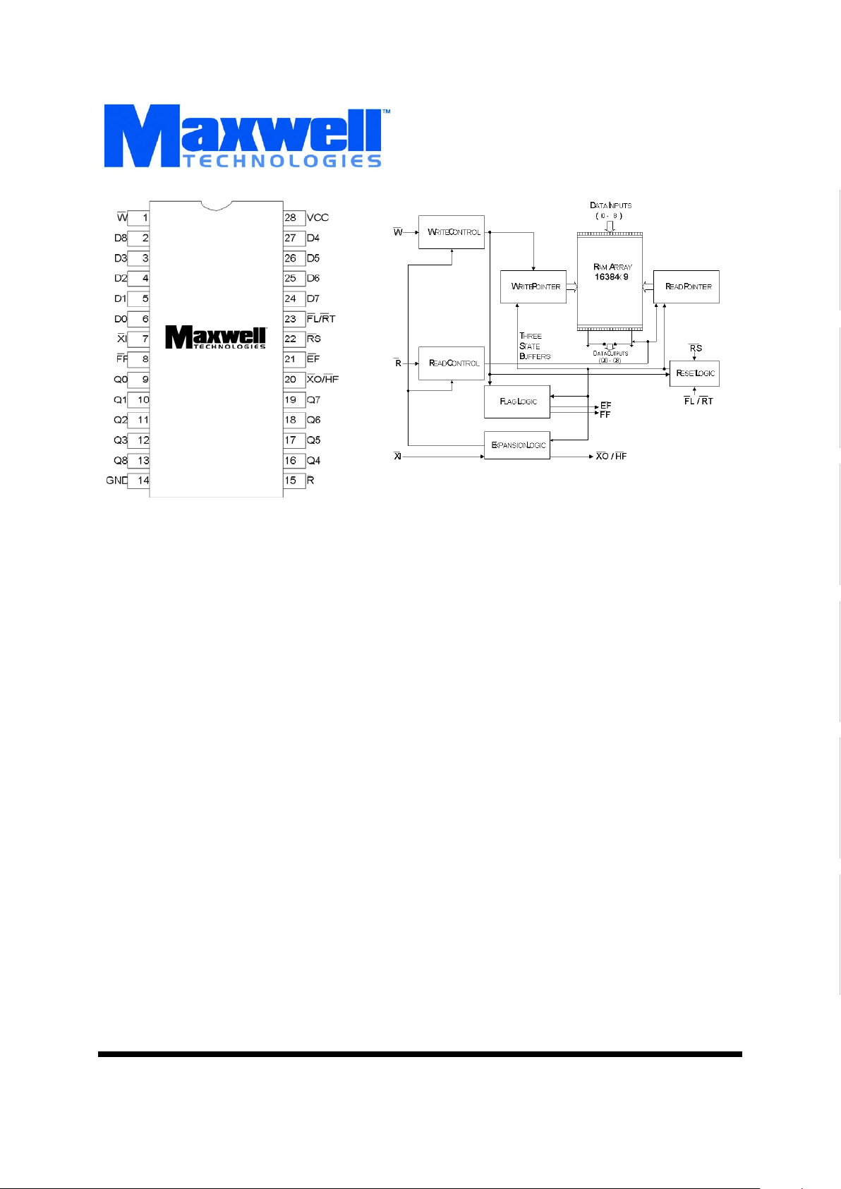
Logic Diagram
Page 2
Memory
2
All data sheets are subject to change without notice
©2001 Maxwell Technologies
All rights reserved.
High-Speed Epi-CMOS (16K x 9-Bit) Parallel FIFO
7206F
12.19.01 Rev 3
1000572
TABLE 1. 7206F PINOUT DESCRIPTION
PIN SYMBOL DESCRIPTION
1WWrite Enable
2 - 6 I8, I3-I0 Inputs
7XI
Expansion In
8
FF
Full Flag
9 - 13 Q0 - Q3, Q8 Outputs
14 GND Ground
15 R
Read Enable
16 - 19 Q4 - Q7 Outputs
20 XO
/HF Expansion Out/Half Full Flag
21 EF
Empty Flag
22 RS
Reset
23 FL
/RT First Load/Retransmit
24 - 27 I7 - I4 Inputs
28 V
CC
Power Supply
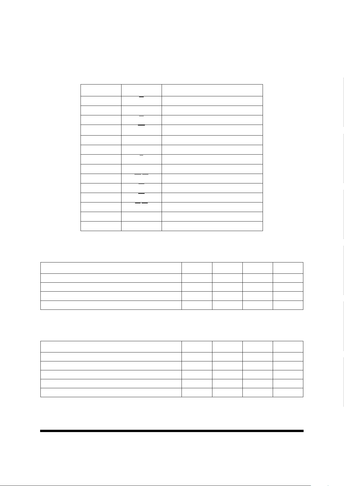
TABLE 2. 7206F ABSOLUTE MAXIMUM RATINGS
PARAMETER SYMBOL MIN MAX UNIT
Positive Supply Voltage V
CC
-0.3 7.0 V
Input or Output Voltage V
IN
GND -0.3 V
CC
+0.3 V
Storage Temperature Range T
S
-65 150
°
C
Operating Temperature Range T
A
-55 125
°
C
TABLE 3. 7206F RECOMMENDED OPERATING CONDITIONS
PARAMETER SYMBOL MIN MAX UNIT
Positive Supply Voltage V
CC
4.5 5.5 V
High Level Input Voltage V
IH
2.2 -- V
Low Level Voltage V
IL
-- 0.8 V
Thermal Impedance
Θ
JC
-- 0.93 °C/W
Operating Temperature Range T
A
-55 125
°
C
Page 3
Memory
3
All data sheets are subject to change without notice
©2001 Maxwell Technologies
All rights reserved.
High-Speed Epi-CMOS (16K x 9-Bit) Parallel FIFO
7206F
12.19.01 Rev 3
1000572
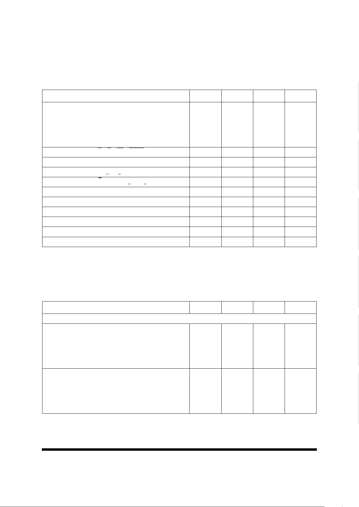
TABLE 4. 7206F DC ELECTRICAL CHARACTERISTICS
(VCC = 5V ± 10%, TA = -55 TO +125 °C UNLESS OTHERWISE SPECIFIED)
P
ARAMETER SYMBOL MIN MAX UNIT
Operating Supply Current
-15
-20
-30
-40
-50
I
CCOP
--
--
--
--
--
165
160
150
140
130
mA
Standby Supply Current (R
= W = RS = FLVRT = VIH)I
CCSB
-- 5 mA
Power Down Current (All Input = V
CC
)I
CCPD
-- 400 µA
Input Leakage Current (0.4V <
VIN < VCC)I
LI
-- ±1 µA
Output Leakage Current (R
= VIH, 0.4V < V
OUT
< VCC)I
LO
-- ±1 µA
Input Low Voltage
1
1. VIH max = V
CC
+ 0.3V. V
IL
min = -0.3V or -1.0V pulse width 50 ns.
V
IL
-- 0.8 V
Input High Voltage
1
V
IH
2.2 -- V
Output Low Voltage (V
CC
min, IOL = 8mA) V
OL
-- 0.4 V
Output High Voltage (V
CC
min, IOH = -2mA) V
OH
2.4 -- V
Input Capacitance
2
2. Guaranteed by design.
C
IN
-- 10 pF
Output Capacitance
2
C
OUT
-- 10 pF
TABLE 5. 7206F TIMING CHARACTERISTICS
1
(VCC = 5V ± 10%, TA = -55 TO +125 °C UNLESS OTHERWISE SPECIFIED)
P
ARAMETER SYMBOL MIN MAX UNITS
Read Cycle
Read Cycle Time
-15
-20
-30
-40
-50
t
RC
25
30
40
50
65
--
--
--
--
--
ns
Access Time
-15
-20
-30
-40
-50
t
A
--
--
--
--
--
15
20
30
40
50
ns
Page 4

Memory
4
All data sheets are subject to change without notice
©2001 Maxwell Technologies
All rights reserved.
High-Speed Epi-CMOS (16K x 9-Bit) Parallel FIFO
7206F
12.19.01 Rev 3
1000572
Read Recovery Time
-15
-20
-30
-40
-50
t
RR
10
10
10
10
15
--
--
--
--
--
ns
Read Pulse Width
2
-15
-20
-30
-40
-50
t
RPW
15
20
30
40
50
--
--
--
--
--
ns
Read Low to Data Low-Z
3
-15
-20
-30
-40
-50
t
RLZ
0
0
5
5
5
--
--
--
--
--
ns
Write HIGH to Data Low-Z
3,4
-15
-20
-30
-40
-50
t
WLZ
3
3
5
5
5
--
--
--
--
--
ns
Data Valid from Read High
-15
-20
-30
-40
-50
t
DV
5
5
5
5
5
--
--
--
--
--
ns
Read High to Data Bus High-Z
3
-15
-20
-30
-40
-50
t
RHZ
--
--
--
--
--
15
15
20
25
30
ns
TABLE 5. 7206F TIMING CHARACTERISTICS
1
(VCC = 5V ± 10%, TA = -55 TO +125 °C UNLESS OTHERWISE SPECIFIED)
P
ARAMETER SYMBOL MIN MAX UNITS
Page 5

Memory
5
All data sheets are subject to change without notice
©2001 Maxwell Technologies
All rights reserved.
High-Speed Epi-CMOS (16K x 9-Bit) Parallel FIFO
7206F
12.19.01 Rev 3
1000572
Write Cycle
Write Cycle Time
-15
-20
-30
-40
-50
t
WC
25
30
40
50
65
--
--
--
--
--
ns
Write Pulse Width
2
-15
-20
-30
-40
-50
t
WPW
15
20
30
40
50
--
--
--
--
--
ns
Write Recovery Time
-15
-20
-30
-40
-50
t
WR
10
10
10
10
15
--
--
--
--
--
ns
Data Set-up Time
-15
-20
-30
-40
-50
t
DS
9
12
18
24
30
--
--
--
--
--
ns
Data Hold Time
-15
-20
-30
-40
-50
t
DH
0
0
0
0
5
--
--
--
--
--
ns
Reset Cycle
Reset Cycle Time
-15
-20
-30
-40
-50
t
RSC
25
30
40
50
65
--
--
--
--
--
ns
Reset Pulse Width
2
-15
-20
-30
-40
-50
t
RS
15
20
30
40
50
--
--
--
--
--
ns
TABLE 5. 7206F TIMING CHARACTERISTICS
1
(VCC = 5V ± 10%, TA = -55 TO +125 °C UNLESS OTHERWISE SPECIFIED)
P
ARAMETER SYMBOL MIN MAX UNITS
Page 6

Memory
6
All data sheets are subject to change without notice
©2001 Maxwell Technologies
All rights reserved.
High-Speed Epi-CMOS (16K x 9-Bit) Parallel FIFO
7206F
12.19.01 Rev 3
1000572
Reset Set-up Time
3
-15
-20
-30
-40
-50
t
RSS
20
30
30
50
60
--
--
--
--
--
ns
Reset Recovery Time
-15
-20
-30
-40
-50
t
RSR
10
10
10
10
15
--
--
--
--
--
ns
Retransmit Cycle
Retransmit Cycle TIme
-15
-20
-30
-40
-50
t
RTC
25
30
40
50
65
--
--
--
--
--
ns
Retransmit Pulse Width
2
-15
-20
-30
-40
-50
t
RT
15
20
30
40
50
--
--
--
--
--
ns
Retransmit Set-up Time
3
-15
-20
-30
-40
-50
t
RTS
15
20
30
40
50
--
--
--
--
--
ns
Retransmit Recovery Time
-15
-20
-30
-40
-50
t
RTR
10
10
10
10
15
--
--
--
--
--
ns
Flags
Reset to EF
Low
-15
-20
-30
-40
-50
t
EFL
--
--
--
--
--
25
30
30
50
65
ns
TABLE 5. 7206F TIMING CHARACTERISTICS
1
(VCC = 5V ± 10%, TA = -55 TO +125 °C UNLESS OTHERWISE SPECIFIED)
P
ARAMETER SYMBOL MIN MAX UNITS
Page 7

Memory
7
All data sheets are subject to change without notice
©2001 Maxwell Technologies
All rights reserved.
High-Speed Epi-CMOS (16K x 9-Bit) Parallel FIFO
7206F
12.19.01 Rev 3
1000572
Reset to HF/FF High
-15
-20
-30
-40
-50
t
HFH
, t
FFH
--
--
--
--
--
25
30
30
50
65
ns
Read Low to EF
Low
-15
-20
-30
-40
-50
t
REF
--
--
--
--
--
15
20
30
40
50
ns
Read High to FF
High
-15
-20
-30
-40
-50
t
RFF
--
--
--
--
--
17
20
30
40
50
ns
Read Pulse Width after EF
High
-15
-20
-30
-40
-50
t
RPE
15
20
30
40
50
--
--
--
--
--
ns
Write High to EF
High
-15
-20
-30
-40
-50
t
WEF
--
--
--
--
--
15
20
30
40
50
ns
Write Low to FF
Low
-15
-20
-30
-40
-50
t
WFF
--
--
--
--
--
20
20
30
40
50
ns
Write Low to HF
Flag Low
-15
-20
-30
-40
-50
t
WHF
--
--
--
--
--
30
30
30
50
65
ns
TABLE 5. 7206F TIMING CHARACTERISTICS
1
(VCC = 5V ± 10%, TA = -55 TO +125 °C UNLESS OTHERWISE SPECIFIED)
P
ARAMETER SYMBOL MIN MAX UNITS
Page 8

Memory
8
All data sheets are subject to change without notice
©2001 Maxwell Technologies
All rights reserved.
High-Speed Epi-CMOS (16K x 9-Bit) Parallel FIFO
7206F
12.19.01 Rev 3
1000572
Read High to HF Flag High
-15
-20
-30
-40
-50
t
RHF
--
--
--
--
--
30
30
30
50
65
ns
Write Pulse Width after FF
High
-15
-20
-30
-40
-50
t
WPF
15
20
30
40
50
--
--
--
--
--
ns
Read/Write LOW to XO
LOW
-15
-20
-30
-40
-50
t
XOL
--
--
--
--
--
15
20
30
40
50
ns
Read/Write LOW to XO
HIGH
-15
-20
-30
-40
-50
t
XOH
--
--
--
--
--
15
20
30
40
50
ns
XI
Pulse Width
-15
-20
-30
-40
-50
t
XI
15
20
30
40
50
--
--
--
--
--
ns
XI
Recovery Time
-15
-20
-30
-40
-50
t
XIR
10
10
10
10
10
--
--
--
--
--
ns
XI
Set-up Time
-15
-20
-30
-40
-50
t
XIS
10
10
10
15
15
--
--
--
--
--
ns
1. V
CC
= +5V±10%, TA = +25 °C; use switching test circuit. AC tests are performed with input rise and fall times of 5 ns or less,
timing reference levels of 1.5V, input pulse levels of 0 to 3.0V and the output load circuit, unless otherwise specified.
TABLE 5. 7206F TIMING CHARACTERISTICS
1
(VCC = 5V ± 10%, TA = -55 TO +125 °C UNLESS OTHERWISE SPECIFIED)
P
ARAMETER SYMBOL MIN MAX UNITS
Page 9

Memory
9
All data sheets are subject to change without notice
©2001 Maxwell Technologies
All rights reserved.
High-Speed Epi-CMOS (16K x 9-Bit) Parallel FIFO
7206F
12.19.01 Rev 3
1000572
FIGURE 1. RESET
FIGURE 2. ASYNCHRONOUS WRITE AND READ OPERATION
FIGURE 3. FULL FLAG TIMING FROM LAST WRITE TO FIRST READ
2. Pulse widths less than minimum value are not allowed.
3. Values guaranteed by design, not currently tested.
4. Only applies to read data flow-through mode.
Page 10

Memory
10
All data sheets are subject to change without notice
©2001 Maxwell Technologies
All rights reserved.
High-Speed Epi-CMOS (16K x 9-Bit) Parallel FIFO
7206F
12.19.01 Rev 3
1000572
FIGURE 4. EMPTY FLAG TIMING FROM LAST READ TO FIRST WRITE
FIGURE 5. RETRANSMIT
FIGURE 6. EMPTY FLAG TIMING
FIGURE 7. FULL FLAG TIMING
Page 11

Memory
11
All data sheets are subject to change without notice
©2001 Maxwell Technologies
All rights reserved.
High-Speed Epi-CMOS (16K x 9-Bit) Parallel FIFO
7206F
12.19.01 Rev 3
1000572
FIGURE 8. HALF-FULL FLAG TIMING
FIGURE 9. EXPANSION OUT
FIGURE 10. EXPANSION IN
FIGURE 11. READ DATA FLOW FOR THROUGH MODE
Page 12

Memory
12
All data sheets are subject to change without notice
©2001 Maxwell Technologies
All rights reserved.
High-Speed Epi-CMOS (16K x 9-Bit) Parallel FIFO
7206F
12.19.01 Rev 3
1000572
FIGURE 12. WRITE DATA FLOW FOR THROUGH MODE
Page 13

Memory
13
All data sheets are subject to change without notice
©2001 Maxwell Technologies
All rights reserved.
High-Speed Epi-CMOS (16K x 9-Bit) Parallel FIFO
7206F
12.19.01 Rev 3
1000572
F28-07
Note: All dimensions in inches
28 PIN RAD-PAK® FLAT PACKAGE
SYMBOL DIMENSION
MIN NOM MAX
A 0.129 0.142 0.155
b 0.015 0.017 0.022
c 0.004 0.005 0.009
D -- 0.720 0.740
E 0.400 0.410 0.420
E1 -- -- 0.440
E2 0.180 0.250 --
E3 0.005 0.080 --
e 0.050 BSC
L 0.390 0.400 0.410
Q 0.021 0.033 0.045
S1 0.005 0.067 --
N28
Page 14

Memory
14
All data sheets are subject to change without notice
©2001 Maxwell Technologies
All rights reserved.
High-Speed Epi-CMOS (16K x 9-Bit) Parallel FIFO
7206F
12.19.01 Rev 3
1000572
Important Notice:
These data sheets are created using the chip manufacturers published specifications. Maxwell Technologies verifies
functionality by testing key parameters either by 100% testing, sample testing or characterization.
The specifications presented within these data sheets represent the latest and most accurate information available to
date. However, these specifications are subject to change without notice and Maxwell Technologies assumes no
responsibility for the use of this information.
Maxwell Technologies’ products are not authorized for use as critical components in life support devices or systems
without express written approval from Maxwell Technologies.
Any claim against Maxwell Technologies must be made within 90 days from the date of shipment from Maxwell Technologies. Maxwell Technologies’ liability shall be limited to replacement of defective parts.
Page 15

Memory
15
All data sheets are subject to change without notice
©2001 Maxwell Technologies
All rights reserved.
High-Speed Epi-CMOS (16K x 9-Bit) Parallel FIFO
7206F
12.19.01 Rev 3
1000572
Product Ordering Options
Model Number
Feature
Option Details
7206F
RP
F X
-XX
Access Time
Screening Flow
Package
Radiation Feature
Base Product
Nomenclature
15 = 15 ns
20 = 20 ns
30 = 30 ns
40 = 40 ns
50 = 50 ns
Monolithic
S = Maxwell Class S
B = Maxwell Class B
E = Engineering (testing @ +25°C
)
I = Industrial (testing @ -55°C,
+25°C, +125°C)
F = Flat Pack
RP = R
AD-PAK® package
High-Speed Epi-CMOS (16K x 9Bit) Parallel FIFO
 Loading...