

Page 1
查询150KR30A供应商
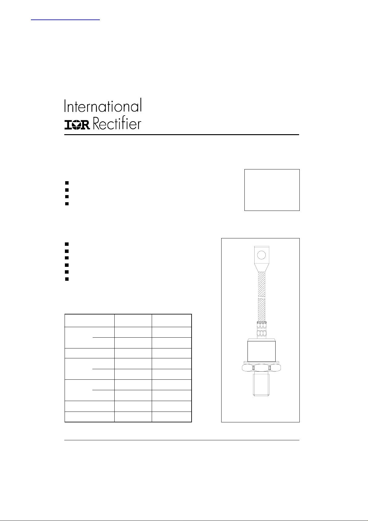
STANDARD RECOVERY DIODES Stud Version
Features
Alloy diode
High current carrying capability
High surge current capabilities
Stud cathode and stud anode version
Bulletin I2037 rev. B 03/03
SERIES
45L(R), 150K/ KS(R)
150A
Typical Applications
Battery charges
Welders
Machine tool controls
High power drives
Medium traction applications
Freewheeling diodes
Major Ratings and Characteristics
Parameters 45L /150K Units
I
F(AV)
@ T
C
I
F(RMS)
I
FSM
I2t@
V
RRM
T
J
@ 50Hz 3570 A
@ 60Hz 3740 A
50Hz 64 KA2s
@ 60Hz 58 KA2s
range 100 to 600 V
150 A
150 °C
235 A
- 40 to 200 °C
case style
DO-205AA (DO-8)
www.irf.com
1
Page 2
45L(R), 150K/ KS(R) Series
Bulletin I2037 rev. B 03/03
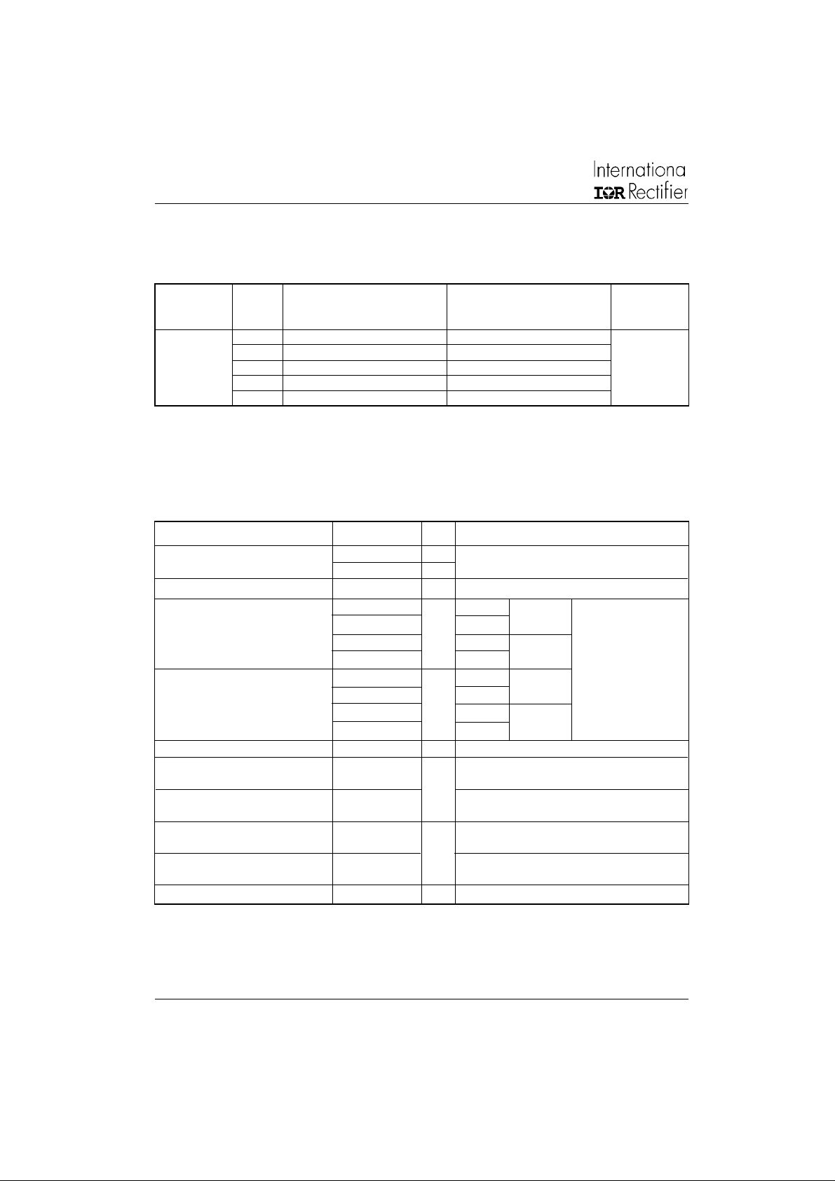
ELECTRICAL SPECIFICATIONS
Voltage Ratings
Voltage V
Type number Code peak reverse voltage repetitive peak rev. voltage @ T
10 100 200
45L(R)
150K(R)
150KS(R)
20 200 300 35
30 300 400
40 400 500
60 600 720
Forward Conduction
Parameter 45L /150K Units Conditions
I
Max. average forward current 150 A 180° conduction, half sine wave
F(AV)
@ Case temperature 150 °C
I
Max. RMS forward current 235 A DC @ 142°C case temperature
F(RMS)
Max. peak, one-cycle forward, 3570 t = 10ms No voltage
I
FSM
non-repetitive surge current 3740 t = 8.3ms reapplied
2
I
t Maximum I2t for fusing 64 t = 10ms No voltage Initial TJ = TJ max.
2
I
√t Maximum I2√t for fusing 640 KA2√s t = 0.1 to 10ms, no voltage reapplied
Low level value of threshold
V
F(TO)1
voltage
V
High level value of threshold
F(TO)2
voltage
r
Low level value of forward
1
f
slope resistance
r
High level value of forward
2
f
slope resistance
V
Max. forward voltage drop 1.33 V Ipk= 471A, TJ = 25°C, tp = 10ms sinusoidal wave
FM
, maximum repetitive V
RRM
VVmA
3000 t = 10ms 100% V
3140 t = 8.3ms reapplied Sinusoidal half wave,
58 t = 8.3ms reapplied
45 t = 10ms 100% V
41 t = 8.3ms reapplied
0.67 (16.7% x π x I
0.83 (I > x π x I
1.42 (16.7% x π x I
0.91 (I > x π x I
A
KA2s
V
mΩ
, maximum non- I
RSM
RRM
RRM
< I < π x I
F(AV)
),TJ = TJ max.
F(AV)
F(AV)
),TJ = TJ max.
F(AV)
< I < π x I
F(AV)
F(AV)
), TJ = TJ max.
), TJ = TJ max.
RRM
= 175°C
J
max.
2 www.irf.com
Page 3
45L(R), 150K/ KS(R) Series
Bulletin I2037 rev. B 03/03
Thermal and Mechanical Specifications
Parameter 45L /150K Units Conditions
TJMax. junction operating temperature range -40 to 200
Max. storage temperature range -40 to 200
T
stg
R
Max. thermal resistance, junction to case 0.25 DC operation
thJC
R
Max. thermal resistance, case to heatsink 0.10 Mounting surface, smooth, flat and greased
thCS
T Mounting torque Min. 14.1 (125)
45L Max. 17.0 (150)
Min. 12.2 (108)
Max. 15.0 (132)
150K Min. 11.3 (100)
150KS Max. 14.1 (125)
Min. 9.5 (85)
Max. 12.5 (110)
wt Approximate weight 100 (3.5) g (oz)
45L DO-205AC (DO-30)
Case style 150K-A DO-205AA (DO-8) See Outline Table
150KS B-42
∆R
Conduction
thJC
(The following table shows the increment of thermal resistence R
thJC
Conduction angle Sinusoidal conduction Rectangular conduction Units Conditions
180° 0.031 0.023 T
120° 0.038 0.040
90° 0.048 0.053
60° 0.071 0.075
30° 0.120 0.121
°C
K/W
Not lubricated threads
Nm
(lbf-in)
Lubricated threads
Not lubricated threads
Nm
(lbf-in)
Lubricated threads
when devices operate at different conduction angles than DC)
= TJ max.
J
K/W
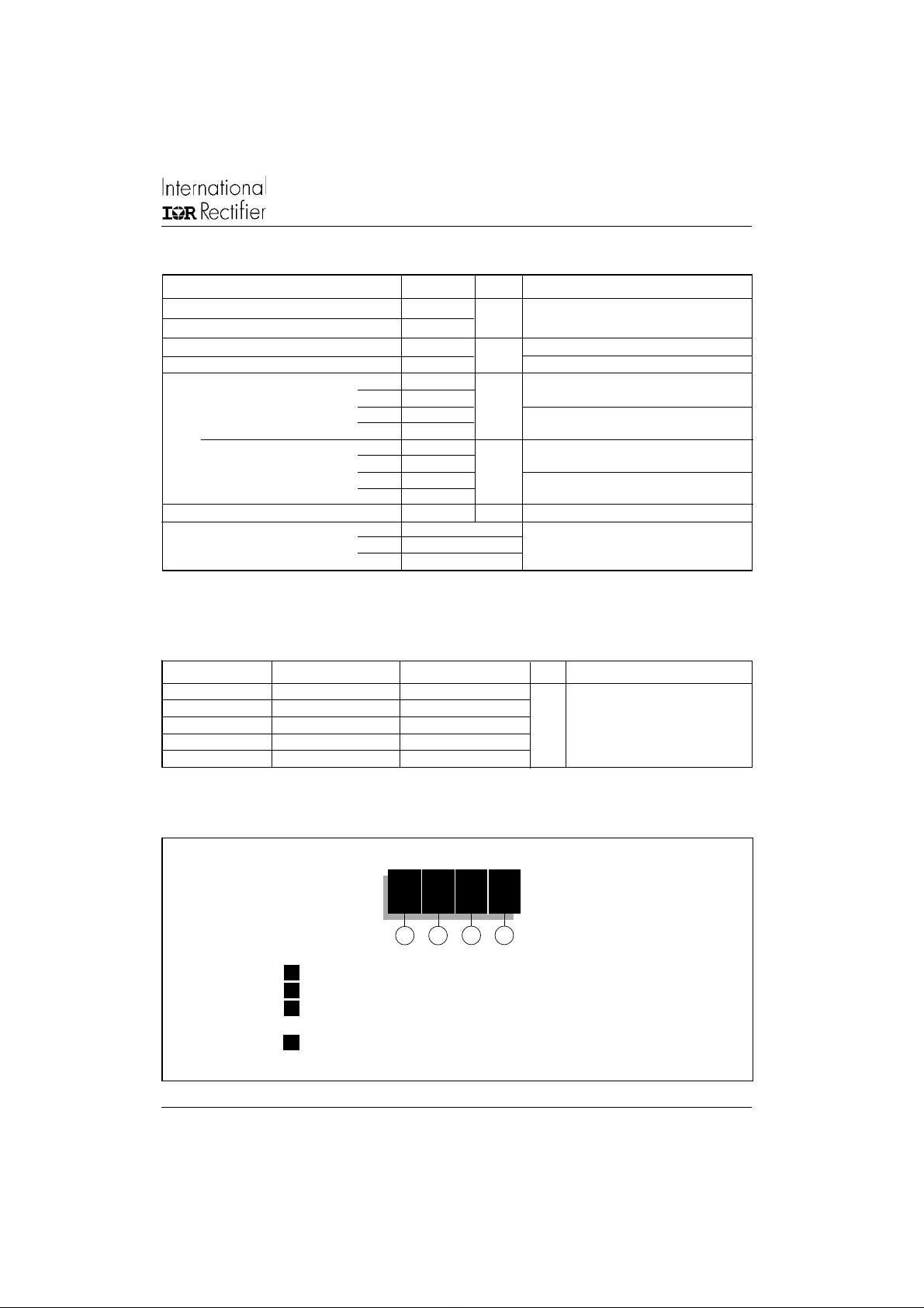
Ordering Information Table
Device Code
1 - 45 = Standard version
2 - L = Essential Part Number
3 - R = Stud Reverse Polarity (Anode to Stud)
4 - Voltage code: Code x 10 = V
www.irf.com
45 L R 60
4
3
2
1
None = Stud Normal Polarity (Cathode to Stud)
(See Voltage Ratings table)
RRM
3
Page 4

45L(R), 150K/ KS(R) Series
Bulletin I2037 rev. B 03/03
Ordering Information Table
Device Code
15 0 K R 60 A
Outline Table
1 2
1 - 15 = Essential Part Number
2 - 0 = Standard Device
3 - Case Style
K = DO205AA (DO-8)
KS = B-42
4 - R = Stud Reverse Polarity (Anode to Stud)
None = Stud Normal Polarity (Cathode to Stud)
5 - Voltage code: Code x 10 = V
6 - A = Essential Part Number for 150K (Omitted for 150KS)
NOTE: For Metric Device M12 x 1.75 Contact Factory
3
4 5
RRM
6
(See Voltage Ratings table)
DO-205AC (DO-30)
45L
Case Style
All dimensions in millimeters (inches)
4 www.irf.com
Page 5

Outline Table
27.17 (1.070)
2.03 (0.080)
21.47 (0.843)
10.2 (0.401)
37.13 (1.462)
3/8"24UNF-2A
12.50 (0.492)
11.70 (0.460)
21.20 (0.835)
9.50 (0.374)
4.08 (0.161)
4.34 (0.171)
DIA.
26.22 (1.032)
1.27 (0.050)
4.09 (0.161)
3.70 (0.146)
7.50 (0.295)
33.83 (1.332)
9.2 (0.362)
6.76 (0.266)
6.25 (0.246)
18.00 (0.708)
14.00 (0.551)
45L(R), 150K/ KS(R) Series
Bulletin I2037 rev. B 03/03
150K
Case Style
DO-205AA (DO-8)
* FOR METRIC DEVICE: M12 X 1.75
CONTACT FACTORY
Case Style B-42
www.irf.com
All dimensions in millimeters (inches)
150KS
5
Page 6

45L(R), 150K/ KS(R) Series
Bulletin I2037 rev. B 03/03
200
190
45L...,1 5 0 ... Series
R (DC) = 0.25 K /W
thJC
180
Conduction Angle
170
160
30°
60°
150
140
Maxi mu m A ll owable Case T emper atur e ( °C)
0 20406080100120140160
90°
Average Forward C urrent ( A)
Fig. 1 - Current Ratings Characteristics
180
160
140
120
180°
120°
90°
60°
30°
RMS Lim it
100
80
60
40
20
0
Maximu m Average For wa rd Power Loss ( W)
0
40 80 120
Average Forward Current (A)
Fig. 3 - Forward Power Loss Characteristics
120°
180°
Conduction Angle
45L..., 15 0 ... Series
T = 200°C
J
200
190
45L..., 15 0 ... Series
R (DC) = 0.25 K /W
thJC
180
Conduction Period
170
160
30°
60°
150
90°
120°
140
Maximum Allowable Case Temperature (°C)
0 50 100 150 200 250
Average Forwar d Current ( A)
Fig. 2 - Current Ratings Characteristics
0
.
0.6
4
K
K
/
/W
0
.
8
K
/
1
K
/
W
1
.
5
K
/
W
2
K
/
W
3
K
/
W
25 50 75 100 125 150 175 200
160
W
W
R
0
0
.
.
3
2
t
h
K
K
S
/
/
A
W
W
=
0
.
1
K
/
W
D
e
l
t
a
R
Max imu m A llowable Ambient Temperature (° C )
180°
DC
250
DC
180°
200
120°
90°
60°
150
100
30°
RMS Lim i t
50
0
Maximum Av erage Forward Power Loss (W)
0 50 100 150 200
Average Forward Cu rren t (A)
Conduction Period
45L..., 150... S eries
T = 200°C
J
0
.
0
3
.
4
K
/
W
0
.
6
K
/
W
0
.
8
K
/
W
1
K
/
W
1
.
5
K
/
W
2
K
/
W
3
K
/
W
25 50 75 100 125 150 175 200
250
Max imu m A llowable Am bient Temperatu re (°C)
R
0
.
t
2
h
S
K
K
/
A
/
W
W
=
0
.
1
K
/
W
D
e
l
t
a
R
Fig. 4 - Forward Power Loss Characteristics
6 www.irf.com
Page 7

45L(R), 150K/ KS(R) Series
Bulletin I2037 rev. B 03/03
3500
At Any Rated Load Condi tion A nd With
Rated V Appl ied Following Surge.
RRM
3000
2500
Initial T = 2 00°C
J
@ 60 Hz 0.0083 s
@ 50 Hz 0.0100 s
4000
Maximum Non Repetitive Surge Cu rren t
3500
3000
Versus Pulse Trai n Duration .
No Voltage Reapplied
Rated V Reappl ied
Initial T = 200°C
RRM
2500
2000
2000
1500
1000
45L..., 150... Series
Peak Half S ine Wave Forward Current (A)
500
1 10 100
Number Of Equal Amplitude Half Cycle Current Puls es (N)
1500
1000
45L..., 15 0 ... Series
Peak Half Si ne Wave Forward Current (A)
500
0.01 0.1 1
Pulse Train Durat ion (s)
Fig. 5 - Maximum Non-Repetitive Surge Current Fig. 6 - Maximum Non-Repetitive Surge Current
10000
1000
T = 25°C
100
J
T = 200°C
J
J
www.irf.com
Instantane ous Forw ard C ur rent (A )
10
00.511.522.533.544.5
45L...,15 0 ... Series
I nstantaneous F orwar d Vo ltage (V)
Fig. 7 - Forward Voltage Drop Characteristics
1
Steady Stat e Value
R = 0 .2 5 K 7W
thJC
Transient Therma l Impedance Z ( K/W)
thJC
(DC Oper ation)
0.1
45L..., 150... Series
0.01
0.001 0.01 0.1 1 10
Sq ua r e Wa v e Pu l se Du r a t i o n ( s)
Fig. 8 - Thermal Impedance Z
Characteristic
thJC
7
Page 8

45L(R), 150K/ KS(R) Series
Bulletin I2037 rev. B 03/03
This product has been designed and qualified for Industrial Level.
IR WORLD HEADQUARTERS: 233 Kansas St., El Segundo, California 90245, USA Tel: (310) 252-7105
Data and specifications subject to change without notice.
Qualification Standards can be found on IR's Web site.
TAC Fax: (310) 252-7309
Visit us at www.irf.com for sales contact information. 03 /03
8 www.irf.com
 Loading...