

Page 1
2SC1213, 2SC1213A
Silicon NPN Epitaxial
Application
• Low frequency amplifier
• Complementary pair with 2SA673 and 2SA673A
Outline
TO-92 (1)
1. Emitter
2. Collector
3. Base
3
2
1
Page 2

2SC1213, 2SC1213A
Absolute Maximum Ratings (Ta = 25°C)
Item Symbol 2SC1213 2SC1213A Unit
Collector to base voltage V
Collector to emitter voltage V
Emitter to base voltage V
Collector current I
Collector power dissipation P
CBO
CEO
EBO
C
C
Junction temperature Tj 150 150 °C
Storage temperature Tstg –55 to +150 –55 to +150 °C
Electrical Characteristics (Ta = 25°C)
2SC1213 2SC1213A
Item Symbol Min Typ Max Min Typ Max Unit Test conditions
Collector to base
breakdown voltage
Collector to emitter
breakdown voltage
Emitter to base
breakdown voltage
Collector cutoff current I
DC current tarnsfer ratio hFE*
Collector to emitter
saturation voltage
Base to emitter voltage V
Notes: 1. The 2SC1213 and 2SC1213A are grouped by hFE as follows.
2. Pulse test
BCD
60 to 120 100 to 200 160 to 320
V
(BR)CBO
V
(BR)CEO
V
(BR)EBO
CBO
h
FE
V
CE(sat)
BE
35 — — 50 — — V IC = 10 µA, IE = 0
35 — — 50 — — V IC = 1 mA, RBE = ∞
4——4 ——VIE = 10 µA, IC = 0
— — 0.5 — — 0.5 µAVCB = 20 V, IE = 0
1
60 — 320 60 — 320 VCE = 3 V, IC =10 mA
10 — — 10 — — VCE = 3 V,
— 0.2 0.6 — 0.2 0.6 V IC = 150 mA,
— 0.64 — — 0.64 — V VCE = 3 V, IC = 10 mA
35 50 V
35 50 V
44V
500 500 mA
400 400 mW
I
= 500 mA*
C
I
= 15 mA*
B
2
2
2
Page 3
2SC1213, 2SC1213A
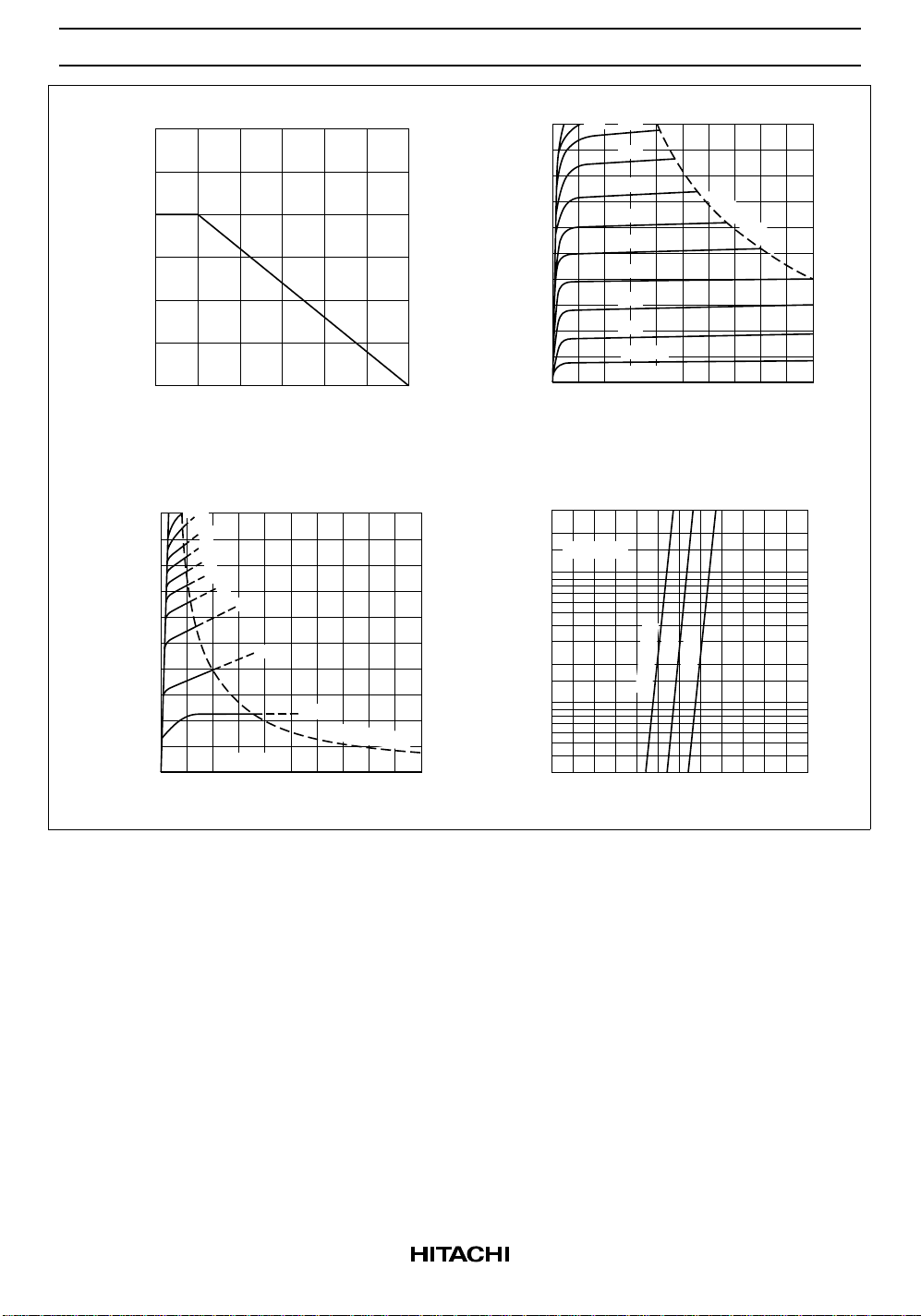
Maximum Collector Dissipation Curve
600
(mW)
C
400
200
Collector Power Dissipation P
0
50
Ambient Temperature Ta (°C)
Typical Output Characteristics (2)
10
500
400
(mA)
C
300
9
8
7
6
5
4
3
2
200
100
Collector Current I
I
= 0
B
0
42
Collector to Emitter Voltage V
100 150
1 mA
P
= 400 mW
C
6810
(V)
CE
Typical Output Characteristics (1)
1.0
100
0.9
0.8
80
(mA)
C
60
40
0.7
0.6
0.5
0.4
0.3
20
Collector Current I
0.2
0.1 mA
IB = 0
0
Collector to Emitter Voltage V
Typical Transfer Characteristics
30
VCE = 3 V
10
(mA)
C
3
1.0
Collector Current I
0.3
0
0.40.2
Base to Emitter Voltage V
P
C
= 400 mW
6810
42
CE
25
–25
Ta = 75°C
0.6 0.8 1.0 1.2
(V)
BE
(V)
3
Page 4
2SC1213, 2SC1213A
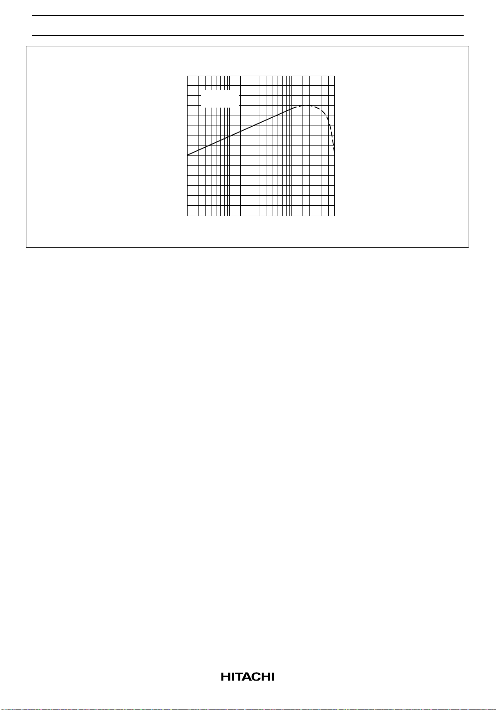
DC Current Transfer Ratio vs.
Collector Current
140
80
60
40
20
0
VCE = 3 V
Ta = 25°C
2
Collector Current I
20510
120
FE
100
DC Current Transfer Ratio h
50 100 200 500
(mA)
C
4
Page 5
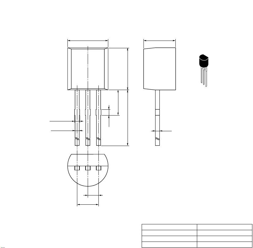
Unit: mm
0.60 Max
0.5 ± 0.1
4.8 ± 0.3
1.27
2.54
0.7
5.0 ± 0.2
2.3 Max
12.7 Min
3.8 ± 0.3
0.5
Hitachi Code
JEDEC
EIAJ
Weight
(reference value)
TO-92 (1)
Conforms
Conforms
0.25 g
 Loading...