

Page 1
92-2448-01 Rev.B
GPIO Multi-Expansion Option
Page 2

Page 3
Overview
This document describes the contents, installation, and use of the I-Class and W-Class GPI/O MultiExpansion option. Additional instructions are included for those using an MCL application. After verifying
the contents of your kit and the tools required, follow the steps below to install and use the option.
DO NOT remove or change the jumper settings on the circuit card included in this option:
equipment damage can occur. Also, for your safety and to avoid damaging the printer,
WARNING
turn OFF the power switch and unplug the AC power cord before starting this installation.
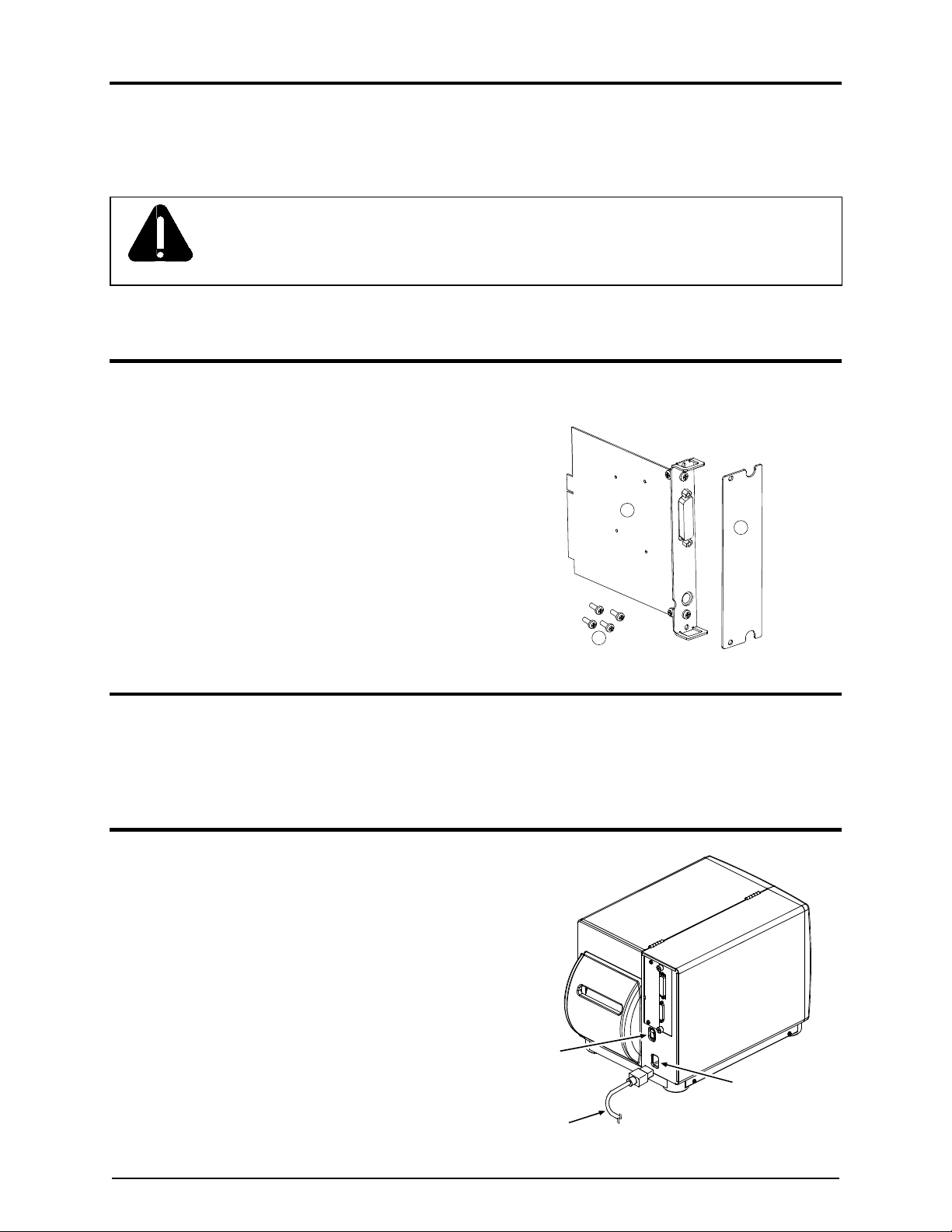
Contents of the GPI/O Multi-Expansion Option Kits
In addition to this document, these kits contain the following items:
GPI/O Multi-Expansion CCA
Rear Cover Plate
Screws, (4) M4 x 12
Tools Required
To install this option, you will need a Phillips screwdriver.
Step 1: Preparing the Printer
1
2
3
A) Turn OFF the Power Switch and unplug
the Power Cord from the AC Receptacle.
Power Switch
AC Receptacle
Power Cord
1
Page 4
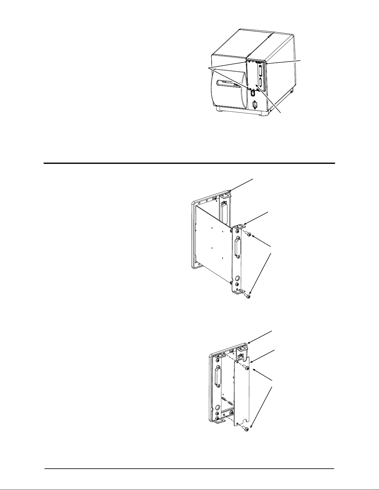
B) Remove the two Screws that secure the
Cover Plate to the Card Cage, and then
remove the Cover Plate.
Card Cage
Screws
Step 2: Installing the GPI/O Multi-Expansion CCA
A) Slide the GPI/O Multi-Expansion CCA
(Item ) into leftmost slot of the Card Cage,
as shown, and then firmly push the CCA to
seat it into the backplane connector.
B) Secure the GPI/O Multi-Expansion CCA
using two Screws (Item ).
Cover Plate
Card Cage
GPI/O
Multi-Expansion CCA
Screws
C) Position the Cover Plate (Item ) on the
Card Cage, as shown, and secure it using
two Screws (Item ).
D) Plug the Power Cord into the AC
Receptacle and turn ON the printer to
complete the installation. Proceed to Step 3
to setup the option.
Card Cage
Cover Plate
Screws
2
Page 5

Step 3: Setup and Configuration
The GPI/O Multi-Expansion CCA has the following features and can be configured according to your
needs (unless otherwise noted, reference the Operator’s Manual for additional setup information, or
consult your software package for usage details):
Flash Expansion – 8 megabytes of configurable Flash Memory for storage of label formats, fonts,
and graphics. (Note that when ILPC Fonts are installed, four Mbytes will remain for other storage
uses.)
Expansion Module Designator Memory Allocation
F
Z
4 MB Flash –ILPC Option – protected, if installed.
4 MB Flash – Configurable.
You can view available memory by printing a Configuration Label: Press the TEST Key. Then, using
the FWD Key, scroll to PRINT CONFIGURATION and press the TEST Key again.
Memory Modules can be
verified on the
Configuration Label.
PRESENT ADJUST
64 DOTS
PRINTER OPTIONS
MODULES
A: NOT INSTALLED
B: NOT INSTALLED
D: FORMATTED
F: FORMATTED
G: NOT INSTALLED
X: NOT INSTALLED
Y: FORMATTED
Z: FORMATTED
PRESENT SENSOR
NOT INSTALLED
CUTTER
NOT INSTALLED
SCANNER:
MODE
PICKET FENCE
The printer’s menu system (under PRINTER OPTIONS / MODULES) offers a complete compliment
PARALLEL PORT B:
NOT INSTALLED
NIC ADAPTER:
IP ADDRESS
010.012.000.215
SUBNET MASK
255.255.000.000
GATEWAY
010.012.254.254
SNMPTRAP DESTINATION
000.000.000.000
NETWARE
ENABLED
DHCP
DISABLED
HOST SETTINGS:
HOST TI M E OU T
10 SEC
of memory management functions (PRINT DIRECTORY, PRINT FILE, FORMAT MODULE, DELETE
FILE, and PACK MODULE), while the SYSTEM SETTINGS menu branch lets you define the default
storage module.
Real Time Clock – Allows time and date retention for label time-stamping functions. You can set the
printer’s time and date using the SYSTEM SETTINGS menu branch.
When set, the time and date will be retained and then displayed
upon subsequent power-ups.
3
READY
REV
STOP
FWD
ERROR
ENT
Page 6
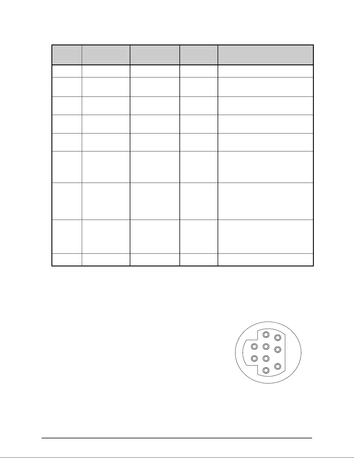
GPIO Port – A General Purpose Input / Output Port for control of printing functions via an external
device (e.g., a label applicator), as detailed below:
Pin
Number
1 Vcc +5 VDC Output +5 VDC power supply.
Signal
Name
Signal
State
Signal
Direction *
Description
2 Ribbon Fault Low Output
3 Paper Fault Low Output
4 Printer Fault Low Output
5 Ribbon Low Programmable Output
6 End of Print Programmable Output
7 Backup Label Programmable Input
8
Start of Print
Signal (SOP)
Programmable
Input
Goes low when a ribbon out
condition is detected.
Goes low when an out of stock
condition is detected.
Goes low when any printer fault
is detected.
Goes high (or low) when a low
ribbon supply is detected.
Goes high (or low) when printing
is complete, typically monitored
to initiate the next Start of Print
sequence.
When received, will position a
presented label for printing -provided that the programmed
present distance is greater than
zero.
When received, begins printing.
(If the printer awaits the SOP
signal, WAITING FOR SIGNAL
will be displayed).
9 Signal Ground Ground N/A Ground return.
*Signal direction is given relative to the printer.
The GPIO Connector pin out configuration, illustrated, right, as
viewed from the rear of the printer. (Use a Mini-DIN male
connector [e.g., Kycon KMDA-9P] when making your interface).
6
9
5
2
1
8
4
7
3
4
Page 7
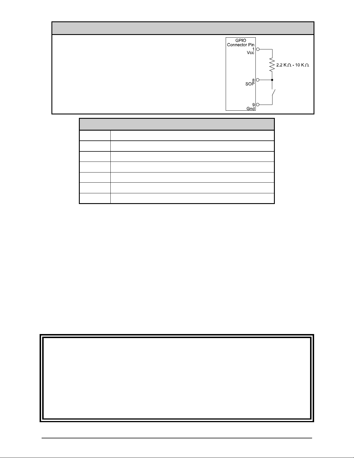
GPIO Start of Print Control
External Start of Print / Backup Label control can be made in
one of the following ways:
By direct connections to Pins 8 & 7 using TTL-level inputs;
or,
By using an interface circuit similar to the one shown right.
For additional interfacing requirements, see the table below.
GPIO Specifications*
Vin max 5.5 VDC maximum input into any pin
VIH 3.8 VDC minimum (high level input voltage)
VIL 1.65 VDC maximum (low level input voltage)
IOH -8 mA typical, - 25 mA maximum (high level output current)
IOL 8 mA typical 25 mA maximum (low level output current)
VOH I
VOL I
*See the SN74AHC244 data sheet for more information.
mA, minimum 3.8 VDC
OH = -8
mA, maximum .44 VDC
OL = 8
ILPC Fonts – For extended font capabilities, the following sets are available:
CG-Times (western European) Scalable font
Kanji Gothic B Scalable font
Simplified Chinese GB Scalable font
Korean Hangul Scalable font
These ILPC font sets arrive pre-loaded. To use them, refer to the Programmer’s Manual, which can
be found on the Datamax-O’Neil Accessories CD or on our web site at www.datamax-oneil.com.
Secondary Serial Port (MCL users only, kit number78-2669-01):
Included on this multipurpose interface card is a secondary RS-232 serial port, one specifically
designed for use with specially configured MCL application programs and firmware. As mentioned
earlier in this document, incorrectly repositioning the jumper blocks on this card could cause damage to
your Datamax-O’Neil printer; therefore, it is important to note that only knowledgeable technicians, after
first consulting with Datamax-O’Neil technical support, must enable this feature. Under the described
normal operation of this card, with its GPIO / applicator interface or font expansion features, there
should be no cause for concern.
5
Page 8

 Loading...