

Page 1
92-2431-01 Rev.C
Thermal Transfer Option
Page 2

Page 3
Overview
This document describes the contents, installation, and use of the Thermal Transfer option for the HClass printer. After verifying the kit contents and tools required, follow the steps below to install and begin
using the option. A ribbon selection guide and a parts listing are also included, so keep this
documentation for future reference.
For your safety and to avoid damaging the equipment, turn ‘Off’ power and unplug the AC
CAUTION
power cord from the printer before beginning this installation.
Contents of the Thermal Transfer Option
This kit contains the following items:
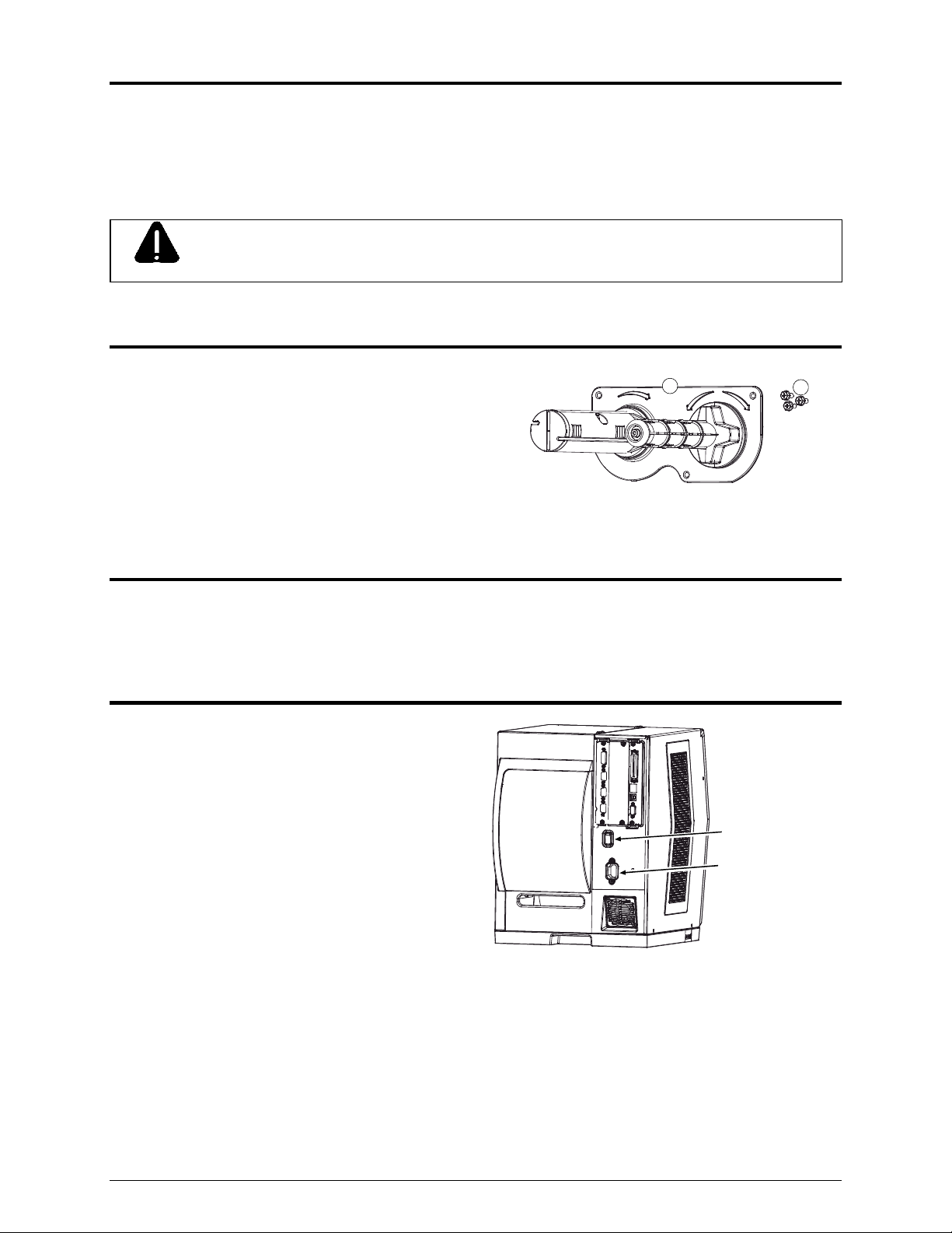
Thermal Transfer Assembly
Mounting Screws (3)
Static Brush (6” and 8” kits only)
1
2
Tools Required
To install this option, you will need a standard and a Phillips screwdriver.
Step 1: Preparing the Printer
A) Turn ‘Off’ the Power Switch and unplug the
power cord from the AC Receptacle.
Power Switch
AC Receptacle
1
Page 4
Step 1: Preparing the Printer (continued…)
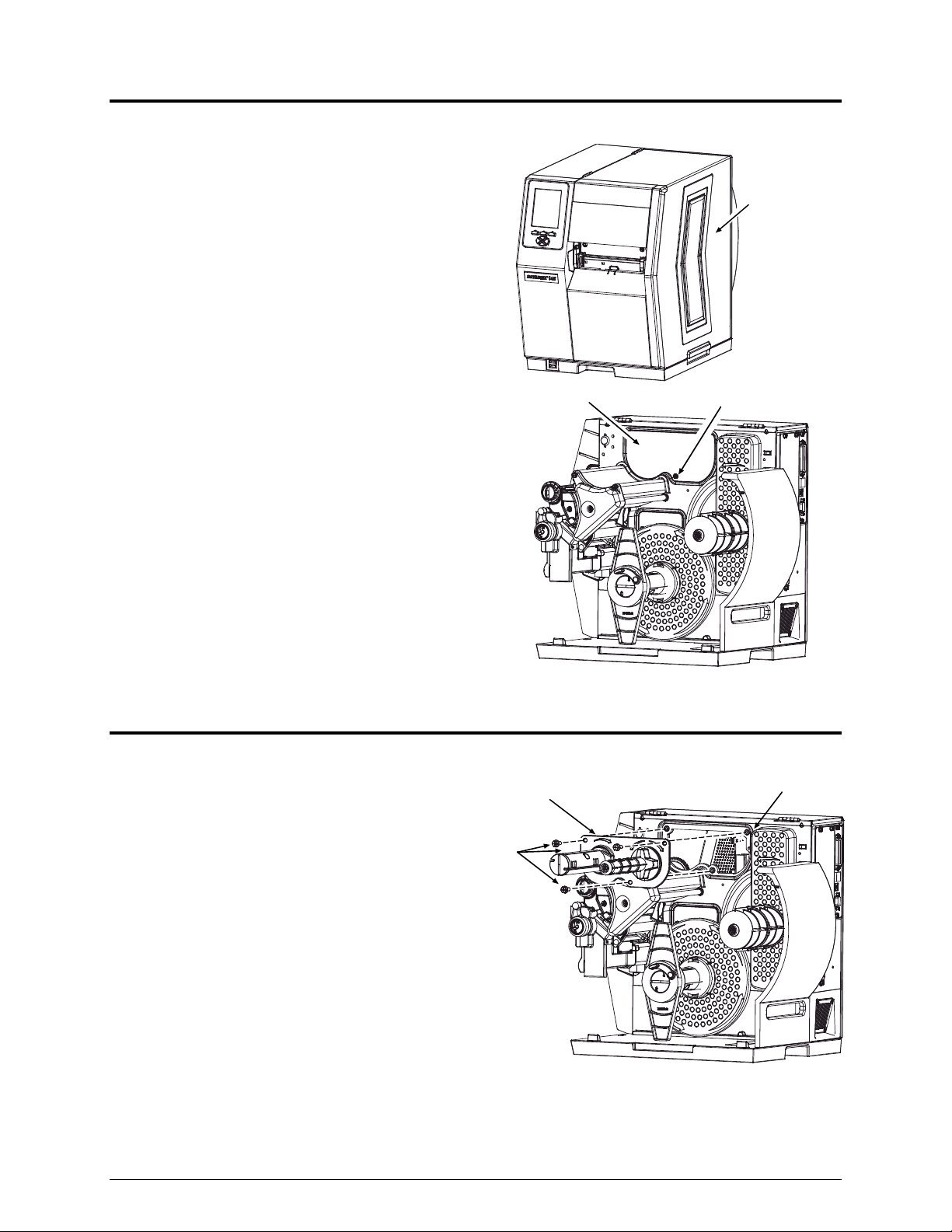
B) Raise the Access Cover. If installed, remove
your media from the printer.
Access
Cover
C) Remove the Cover Screw then the Cover
Plate.
Step 2: Installing the Option
A) Carefully position the Thermal Transfer
Assembly (Item ) onto the Center Plate
of the printer and secure it using the three
Cover Plate
Thermal Transfer
Assembly
Mounting
Screws
Cover Screw
Center
Plate
Mounting Screws (Item ).
2
Page 5

6” and 8” printers only
B) Using a Cotton Swab or cloth, moistened with isopropyl alcohol, gently clean the surface where the
Static Brush will be installed.
Isopropyl alcohol is a flammable solvent; always take the proper precautions when using this substance.
WARNING
C) Peel the backing from the adhesive strip on
the back of the Static Brush and affix the
brush to the printer in the location shown.
Static
Brush
Be sure to locate the Static Brush as
close to the printer’s Centerplate as
possible.
Note: The Static brush should be installed so the bristles are as close to the ribbon without actually touching. It
may be necessary to install a roll of ribbon in order to properly align the brush to the ribbon.
Step 3: Configuring the Printer
Note: During this procedure, consult the Operator’s Manual for detailed front panel instructions.
Configure the printer for the thermal transfer use as follows:
A) Plug the power cord into the AC Receptacle and turn ‘On’ the Power Switch.
B) Press the MENU Button on the printer’s front panel.
C) Press the ENTER Key to select MEDIA SETTINGS, and press the key again to select MEDIA TYPE.
D) Using the DOWN Button, scroll to THERMAL TRANSFER then press the ENTER Key.
E) Press the EXIT Key and then, at the SAVE CHANGES? prompt, press YES.
3
Page 6

Step 4: Aligning the Ribbon Path
Thermal transfer printing relies on a smooth, taut flow of ribbon for consistent print quality; to accomplish
this, some components in the printer may need to be adjusted. Align the ribbon path as follows:
A) Install full width thermal transfer Media into the printer. Install a slightly wider Ribbon onto the
Supply Hub and route it through the printer (see the Operator’s Manual for details). Allow the Ribbon
to feed from the printer along with the Media, as shown below:
Supply Hub
Ribbon
Media
B) Adjust the Media Guide to fit the label width, set the Leveling Cam to the lowest (disengaged)
position, and ensure that the Printhead Pressure is balanced (see the Operator’s Manual for
details).
Printhead
Pressure
Adjustment
Leveling
Cam
Media
Guide
4
Page 7

C) Press the FEED Key several times, until media tracking is normalized through the printer. Then, while
feeding several more labels, observe the flow of the Ribbon from the Supply Hub. Proceed
according to your observations:
If the ribbon flow is rippling, or if bagging is present, proceed to D; or,
If the ribbon flow is evenly tensioned and smooth, proceed to E.
Ribbon
Supply
Hub
FEED
Key
observe
for flow
D) Slightly loosen the Support Cover Screw and, while repeatedly pressing the FEED Key, slowly
adjust the Idler Adjustment Screw to smooth the ribbon flow from the Supply Hub. Afterward,
carefully tighten the Support Cover Screw, and then feed several more labels to verify your
adjustment.
Supply Hub
smooth the ribbon flow
Idler Alignment
Screw
Support Cover
Screw
5
Page 8

E) Wrap the Ribbon in a clockwise direction around the Take-Up Hub. Press the TEST Button on the
Front Panel then use the UP / DOWN Buttons to select the RIBBON TEST LABEL. Select a small
quantity of labels and press the ENTER Key. As the labels are output, observe the flow of the
Ribbon from the Printhead Assembly to the Take-Up Hub. Proceed according to your
observations:
Ribbon
Take-Up
Hub
Printhead
llllllllllllllllllllllllll
Assembly
llllllllllllllllllllllllll
llllllllllllllllllllllllll
llllllllllllllllllllllllll
Front
Panel
observe for flow
If the ribbon flow is smooth, press the CANCEL Key, and then proceed to F; or,
If the ribbon flow is rippling or if bagging is present, slightly loosen both Ribbon Shield Screws
and then move the Ribbon Shield ‘in’ or ‘out’ to smooth the flow of the ribbon. Afterward,
carefully tighten the Ribbon Shield Screws. Print several more labels to verify your adjustment.
When finished, press the CANCEL Key to stop printing.
llllllllllllllllllllllllll
llllllllllllllllllllllllll
llllllllllllllllllllllllll
llllllllllllllllllllllllll
Ribbon Shield
Screws
lllllll llll lll llllllllll lllll
lllllll llll lll llllllllll lllll
6
Ribbon
Shield
Page 9

F) Press the TEST Button then use the UP / DOWN Buttons to select the PRINT QUALITY LABEL or
the TEST LABEL. Set a quantity of labels to print and then press the ENTER Key. After printing
stops, carefully examine the labels for evidence of ribbon wrinkling (i.e., irregular diagonal voids that
extend through printed areas). Proceed according to your examinations:
If no evidence of wrinkling is present on the labels, press the CANCEL Key to stop printing and
complete the procedure; or,
If evidence of wrinkling is present, enter the Test Menu again and reselect the PRINT QUALITY
LABEL or the TEST LABEL. Set a quantity of labels to print and press the ENTER Key. Slightly
loosen the Ribbon Shield Screws then slightly readjust the Ribbon Shield to eliminate the latent
wrinkling. When finished, press the CANCEL Key to stop printing and complete the procedure.
The printer should now be ready for use in thermal transfer mode; however, if you are still experiencing
problems with the installation or application of this option, refer to the troubleshooting guide below.
Troubleshooting
The following table covers common installation and use problems.
If experiencing this problem… Try this solution…
‘RIBBON FAULT’ is indicated on the
printer’s display panel:
Ensure that ribbon is correctly installed and that the
printhead is latched; see the Loading Diagrams on the
printer’s cover or in the Operator’s Manual.
Check the ribbon hubs for obstructions that may be
inhibiting movement.
Ensure that the ribbon core fits snugly on the Supply Hub.
Ensure that the media is not slipping under the ribbon
(usually caused by an incorrect ribbon and media
combination); see Selecting Media and Ribbon, below.
Used ribbon is not being wound by
the Take-Up Hub:
Ensure that the leader has been correctly wound and
secured to the Take-Up Hub.
7
Page 10

If experiencing this problem… Try this solution…
Labels and ribbon advance normally,
but no image is printed:
Examine the used ribbon for an image and proceed
accordingly:
If there is an image on the used ribbon:
Verify that the ribbon was properly loaded. The inked side
of the ribbon must face the media. (To verify the inked side,
press the adhesive backing of a label against the ribbon
surface. Ink will only lift from the coated side of the ribbon.)
Clean the printhead (see the Operator’s Manual). Then flip
the roll of ribbon on the Supply Hub; see the Loading
Diagrams on the printer’s cover or in the Operator’s
Manual.
If there is no image on the used ribbon:
The Heat setting may be too low. Make an adjustment in
your software program or through the printer’s menu
system. (Note that the same functional commands from the
host computer may override the menu settings; see the
Operator’s Manual for details.)
The media and ribbon combination may be incorrect; see
Selecting Media and Ribbon, below.
If you have questions, or if problems persist, contact Datamax-O’Neil Technical Support.
8
Page 11

Selecting Media and Ribbon
Because the media and ribbon used will determine the printer’s heat and speed settings, consider these
factors when selecting your thermal transfer stock and ribbon combination:
The combination of label facestocks / topcoatings and ribbon formulation may affect image quality.
The ribbon backcoating can provide printhead protection and, depending upon the formulation, help
reduce static build-up.
The use of a ribbon that is slightly wider than the media backing material (if any) can protect the
printhead against wear.
The following table is for reference only; for detailed advice, consult a Datamax-O’Neil Media
Representative.
Ribbon
Type
GPR Plus Great Label TTL
GPR Plus
PGR+
Coated and Uncoated Paper,
Tag Stock, some Films, some
Synthetics
Coated and Glossy Paper, Tag
Stock, some Synthetics, Films
Thermal Transfer
Media Type
Inches per
Second
Millimeters per
Second
Print
Energy
Image
Durability
10 – 12 * 254 – 305 * Medium Medium
2 - 10 51 - 254 Medium Medium
2 - 8 51 - 203 Medium Medium
SDR Synthetics, Films 4 - 6 102 - 152 High High
Print Speed
*Highly recommended for optimum print quality at speeds above 10 IPS.
Ribbon Requirements
Ribbon Core:
1.010” .006” (25.6 mm .2 mm) inner diameter; where the core is not
to protrude beyond ribbon’s edge.
Maximum Ribbon Length: 1968 feet (600 meters)
[1]
The ribbon width should exceed the web width of the label (label + liner).
Approved Media
Specially formulated for optimum print quality and maximum printhead life, Datamax-O’Neil media and
ribbons are strongly suggested for use in your printer. The use of non-Datamax-O’Neil materials may
affect the print quality, performance, and life of the printer components (see the Operator’s Manual
Warranty Statement for details). For a current list of approved media and ribbons, contact a Media
Representative at (407) 523-5650.
9
Page 12

 Loading...