

Page 1
92-2435-01 Rev.C
Linear Scanner Option
Page 2

Page 3
Overview
With the H-Class Linear Scanner option and menu-selectable functions that include voiding and
replacement generation, labels can be interrogated at up to 700 times per second to ensure that correct,
readable symbologies have been printed.
Use the sections of this document to find needed information. As a starting point, if your Linear Scanner
arrived factory-installed, see “Controls and Features, Performance, and Configuration” to begin use;
otherwise, proceed to “Installation.”
Installation
If installing the kit, verify the experience level of the installer, the package contents, and the tools needed
before following the steps below.
Only qualified service personnel should perform this installation. For your safety and to
avoid printer damage, always turn OFF the power switch and unplug the AC power cord
CAUTION
before this installation and whenever performing service.
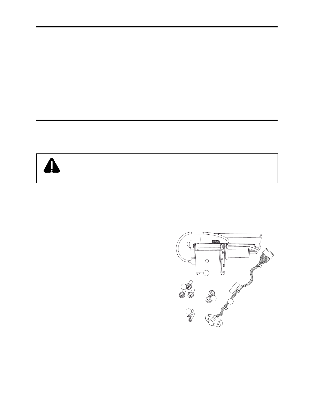
Contents of the Linear Scanner Kit
In addition to this document, this kit contains the following items:
Scanner and Mounting Assembly
Philips Screw (3), M4 x 12
Nut (2), M3 x .5
Philips Screw (2), M3 x 20
1
2
3
5
4
Cable Assembly
Tools Required
To install this option a small standard screwdriver and a Philips screwdriver are needed.
1
Page 4
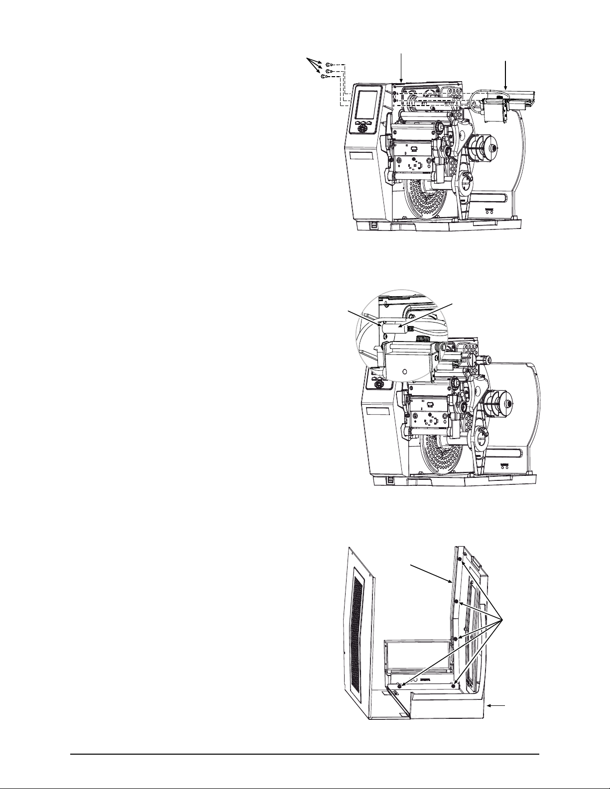
1) Turn OFF the Power Switch and unplug the
power cord from the AC Receptacle.
2) Press down on the Catch, then pull forward to remove
the Door.
Power Switch
AC Receptacle
Catch
Door
3) Raise the Cover. Loosen both Hinge
Screws. Remove the three Cover Screws,
and then lift the Cover off the printer.
Remove any media and ribbon from the
printer.
Cover
Screws
Cover
Hinge
Screws
2
Page 5
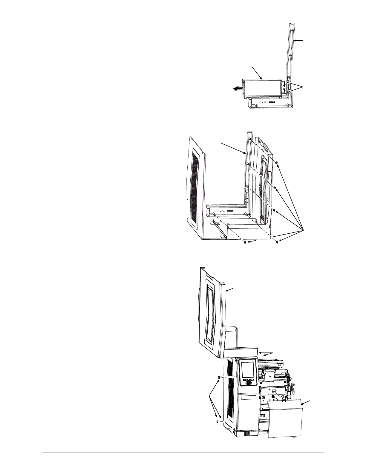
4) Remove the Plug from the Center Plate
Center Plate
Aperture
Plug
Aperture.
5) Secure the mini-din connector of the
Cable Assembly (Item 5) to the Center
Plate Aperture using two Screws (Item
4) and two Nuts (Item 3).
Screws
Center Plate
Aperture
Cable
Assembly
Nuts
6) After routing the Cable Assembly away from movable
parts, attach its 8-pin connector to J13 of the Backplane
CCA.
J13
Backplane
CCA
Cable
Assembly
3
Page 6
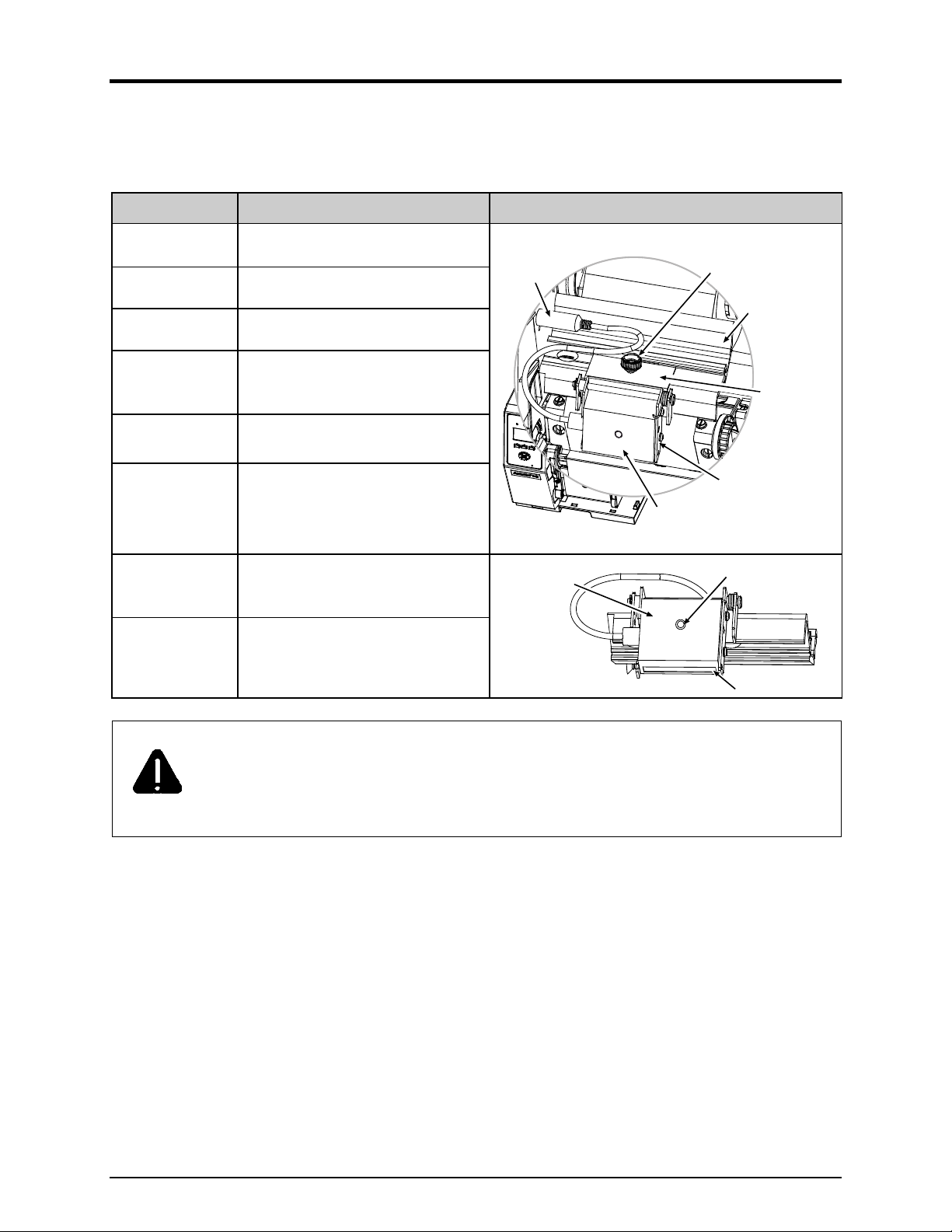
7) Secure the Scanner and Mounting
Assembly (Item 1) to the Center Plate
Screws
Center Plate
Scanner and
Mounting Assembly
using three Screws (Item 2).
8) Connect the Scanner Cable to the Center
Plate Connector.
Center Plate
Connector
Scanner
Cable
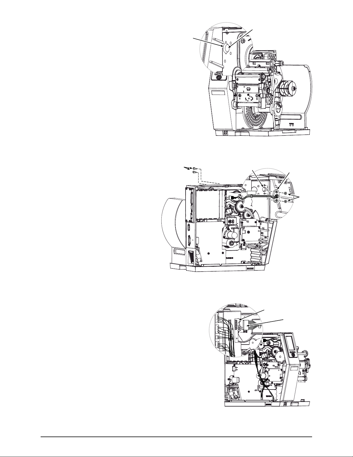
9) Remove the five Screws that secure the Fascia to the
Cover.
4
Fascia
Screws
Cover
Page 7
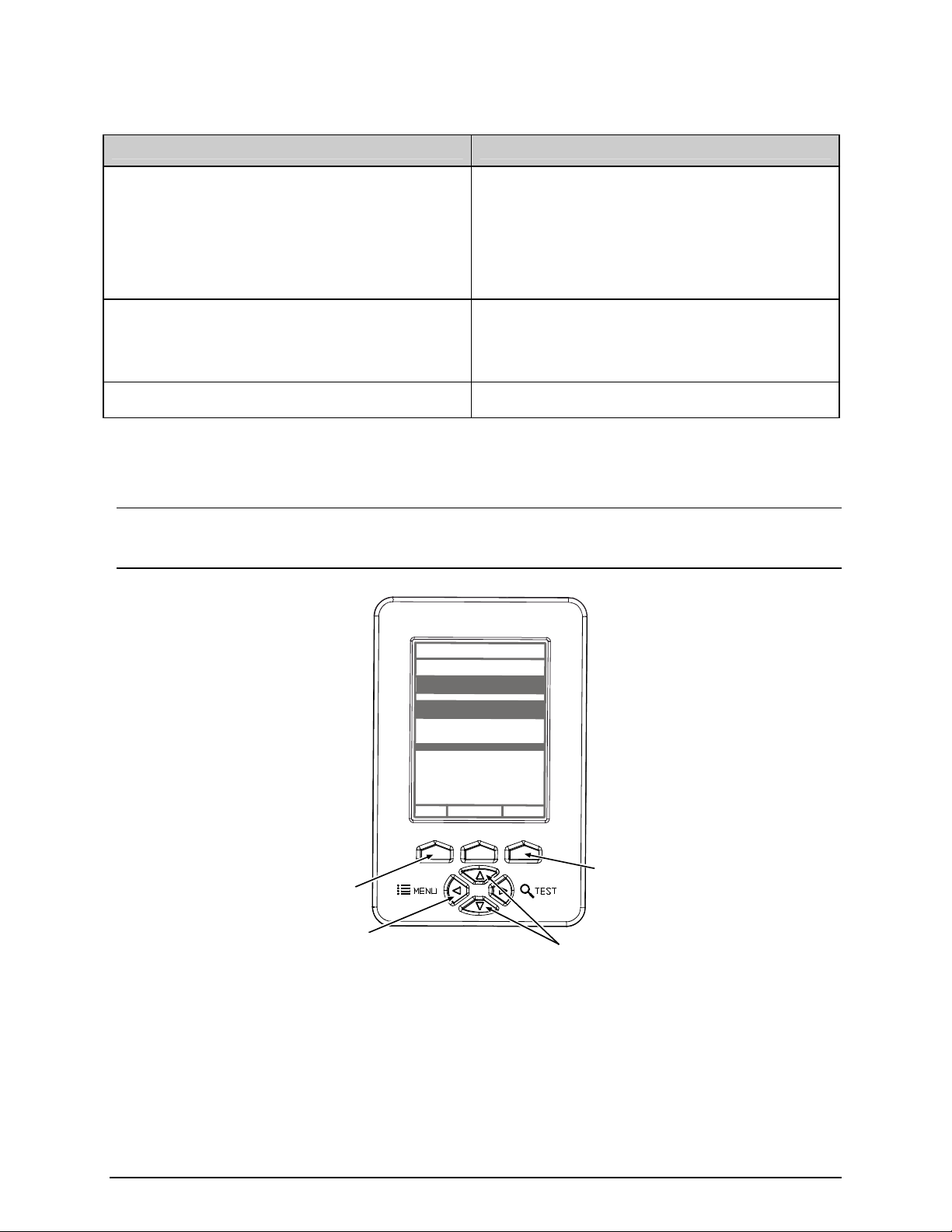
Fascia
10) Press the Tabs of the Lens together. Then slide the Lens off
the Fascia. (Store the Lens in a safe place, for future use.)
Fascia
11) Secure the Fascia to the Cover using the five
previously removed Screws.
Lens
Tabs
Screws
12) Lower the Cover onto the printer. Reinstall and
tighten the three Cover Screws. Tighten both
Hinge Screws. Reinstall the Door and lower
the Cover.
Plug the power cord into the AC
Receptacle. Align the scanner; see “Alignment”
section, below.
Cover
Screws
Cover
Hinge
Screws
Door
5
Page 8
Controls and Features, Performance, and Configuration
This section includes topics on operations.
Controls and Features
Item Function Location
Connector Cable Scanner to printer interface.
Horizontal Mount Lateral position adjustment.
Mounting Bracket Horizontal support.
Spring-loaded holder, also for vertical
Pivoting Mount
Scanner
Thumbscrew
LED
Window
Scanner positioning (scan resolution).
CCD scanning device.
Secures the Scanner to the
Horizontal Mount, for lateral
positioning.
Goes green to signify a “good” read.
Portal for image illumination and
capture; glows red.
The Pivot Mount should never be over-extended. The use of controls, adjustments, or
procedures other than those specified herein may result in hazardous LED light exposure.
CAUTION
Class 1 LED power up to 15 mW in a 0.1 ms pulse at 635-670 nm could be accessible in
the interior of the Linear Scanner.
Connector
Cable
Scanner
Scanner
Thumbscrew
Mounting
Bracket
Horizontal
Mount
Pivoting
Mount
LED
Window
Performance Considerations
Printing with the scanner is a seamless operation; however, consider some important factors that can
affect performance:
6
Page 9

Integrity and Speed
If the primary objective is to ensure that correct data is read over a significant region of the
symbology, maximize integrity by (1) increasing the REDUNDANCY LEVEL or the MIN
READABLE HEIGHT setting, (2) slowing the print speed, and (3) increasing the bar code height.
When emphasizing data accuracy, the allowable maximum throughput rate may be affected.
If the primary objective is to achieve the highest label throughput rate, maximize speed by (1)
decreasing the REDUNDANCY LEVEL or the MIN READABLE HEIGHT setting, and (2)
increasing the print speed. When emphasizing throughput, data reliability may be affected.
Media and Ribbon Selection
For best results use carbon-based inks on matte-finished label stocks to achieve a high print contrast.
Label Layout
For proper recognition, the Linear Scanner must be positioned over the bar codes, and the codes
used and the label layout must meet certain requirements:
The bar codes must be placed in the picket fence orientation, with proper quiet zones, and a
narrow bar resolution that is no less than the scan resolution position.
If encoding the same information in multiple-up bar codes arranged in ordered columns (see
below), allow at least ¼ inch of white space between the rows.
Column
Print
Row
104 104 104
104
104 104
1/4 inch (6.5 mm)
Direction
When printing bar codes on small labels, avoid the possible need for backup repositioning by
placing the code(s) near the leading edge of the label.
Although a reduction of print speed may actually improve throughput, to maintain proper
detection when printing small bar codes at high speeds the following parameters should not be
exceeded:
Minimum Bar Code Height Maximum Print Speed (IPS)*
1/16 inch (1.5 mm) 8
1/8 inch (3 mm) 10
* Inches per Second
7
Page 10
Configuration
A printer equipped with the Linear Scanner arrives with these default settings:
Menu Location Function and Default Setting
MODE = Auto
BARCODES = All, except IATA and codes with
certain addendums
PRINTER OPTIONS SCANNER
SYSTEM SETTINGS FAULT HANDLING
COMMUNICATIONS HOST SETTINGS OPTION FEEDBACK = Disabled
Most settings can be changed via the User Interface, as described below:
BAR CODE COUNT = 00 (Auto Mode)
MIN READABLE HEIGHT = Disabled
REDUNDANCY LEVEL = 2X
IGNORE NO DATA = Disabled
FAULT HANDLING = Standard
VOID DISTANCE = 0.5 Inches
RETRY COUNT = 1
BACKFEED ON CLEAR = Disabled
Note: Before proceeding, ensure that the ADVANCED MENU is selected: Press MENU then go to
SYSTEM SETTINGS MENU MODE ADVANCED MENU and press ENTER.
WED 09:32A 06NOV2006
OFFLINE
PRINTER OPTIONS
MODULES
PRESENT SENSOR
CUTTER
SCANNER
RFID
GPIO PORT
REWINDER
RFID
EXIT
ENTERSYSTEM
ENTER Key
EXIT Key
MENU Button
UP & DOWN
Buttons
To change SCANNER settings –
1) Press MENU. Use DOWN or UP to scroll to PRINTER OPTIONS, and then press ENTER.
2) Scroll to SCANNER and then press ENTER. (See table below for listing.)
3) When finished, press EXIT and then YES at the SAVE CHANGES prompt to complete setup.
8
Page 11
Scanner Menu Item Description
MODE
ENABLED
Sets device power-up detection:
Detection is performed: If found, normal printing and scanning occurs; or, if
not found, a fault will be declared.
DISABLED No detection is performed and no scanning functions will occur.
AUTO
BARCODES
Detection is attempted: If found, normal printing and scanning occurs; or, if
not found, no fault will be declared and no scanning will occur.
Specifies the bar code type(s) for scanning, where:
CODE 39
IATA
CODABAR
INTERLEAVED 2 OF 5
INDUSTRIAL 2 OF 5
CODE 93
CODE 128
MSI/PLESSEY
EAN(13/8)
EAN(13/8)+2
Is / are the type(s) to be checked; see the Class Series 2 Programmer’s
Manual for symbology details.
Note: Enabling only the symbologies to be examined maximizes
throughput.
EAN(13/8)+5
UPC(A/E)
UPC(A/E)+2
UPC(A/E)+5
BARCODE COUNT
(0 – 99)
00
MIN READABLE HEIGHT
1/16 – ½ in (1.5 – 12.5
mm)
DISABLED Operation switches to REDUNDANCY LEVEL.
Sets the number of codes per label to be read.
The scanner will count the specified number (1 to 99) of bar codes per label;
if all are not present a fault is declared.
The default setting (00) enables Auto Mode; this mode, appropriate for most
applications, calculates the number of bar codes present and permits a
variable number of codes to be read per label. See the note below (and
Label Layout) for possible exceptions.
Note: If sent as bitmaps (i.e., imaged) to the printer, enter the
minimum count to be read on each label. Check with your
software application if questioning bar code generation.
Ensures bar code integrity by establishing a minimum vertical read
distance. (The optimum scan rate and consecutive read count for this
distance will be automatically calculated.)
This distance must have identical decodes for the bar code to pass (e.g., a
setting of ¼ requires that .25 inches of the code be 100% readable).
Note: Setting should not exceed 50% of the measured bar code
height.
(continued)
9
Page 12

Scanner Menu Item Description
REDUNDANCY LEVEL
(1X – 6X)
READ BARCODE 2X
AUTO Operation switches to MIN READABLE HEIGHT.
IGNORE NO DATA
DISABLED Checks for correct bar code data in the bar code(s).
ENABLED Ignores the data present in the bar code(s).
SET DEFAULTS
YES / NO
Ensures bar code integrity by specifying a redundant read count.
This count (1 – 6) sets the number of consecutive and identical decodes
that must occur for a bar code to pass.
Allows an override of the verification function, where:
Restores the Linear Scanner settings to the factory default values.
Selecting YES will return these settings:
MODE = Auto
BARCODES = All, except IATA and codes with certain addendums
BAR CODE COUNT = 00 (Auto Mode)
MIN READABLE HEIGHT = Disabled
REDUNDANCY LEVEL = 2X
IGNORE NO DATA = Disabled
To change FAULT HANDLING settings –
1) Press MENU. Press DOWN or UP to scroll to SYSTEM SETTINGS, and then press ENTER.
2) Scroll to FAULT HANDLING and then press ENTER. (See table below for listing.)
3) When finished, press EXIT and then YES at the SAVE CHANGES prompt to complete setup.
Fault Handling Menu Item Description
LEVEL
NO REPRINT
Determines the amount of interaction required to proceed after a fault.
Printing stops and a fault message is displayed. Following correction of the
problem, FEED must be pressed to clear the fault, but the label in process is
not reprinted.
STANDARD
Printing stops and a fault message is displayed. Following correction of the
problem, FEED must be pressed to clear the fault then the label in process is
reprinted.
VOID AND RETRY
Depending upon the RETRY COUNT (see below), one of the following:
• If the count has not been exceeded, VOID is printed (see VOID
DISTANCE) on the failed label and reprinting automatically occurs;
• If the count has been exceeded, printing stops and a fault message is
displayed. Following correction of the problem, FEED must be pressed to
clear the fault before the label in process is reprinted; or,
• If CANCEL is pressed, reprinting is optional: to reprint, press NO; or, to
cancel the reprint, press YES (and press YES again to cancel the batch.)
(continued)
10
Page 13

Fault Handling Menu Item Description
Increases throughput when bar codes reside near the trailing edge (in the
print direction) of the label.
DELAYED SCAN FAULT
VOID RETRY & CONT.
Note: If unreadable, the fault will occur after the next label prints; the
label immediately following a faulted label will not be scanned;
and, since VOID AND RETRY and REPRINT are automatically
disabled, the job can only be cancelled.
VOID is printed if faulted, with reprint attempts occurring automatically, until
the RETRY COUNT has been exceeded and then that label will be skipped
(discarded) and printing will continue to the next label in queue.
VOID DISTANCE
Sets the distance to backup and print VOID on a faulted label.
This distance, measured from the trailing edge (in the print direction) of the
(0.10 to 2.00 in.)
RETRY COUNT
label, indirectly establishes the font size of the message.
Note: VOID will not be printed if insufficient text space exists, or if the
fault occurred after the label was printed.
Sets the number of reprint attempts.
(0 - 3) If the last label printed in this count has been voided, a fault will be declared.
BACKFEED ON CLEAR
Determines the printer's response after a fault is cleared.
ENABLED After fault clearing, backup label positioning will occur.
After fault clearing, no backup label positioning will occur. The printer will
assume that the current position is correct.
DISABLED
Note: If reloading media, the label must be placed in its presented
position.
To change HOST SETTINGS (for data capturing applications) –
Note: Bi-directional cabling and communications must be used.
1) Press MENU. Use DOWN or UP to scroll to COMMUNICATIONS, and then press ENTER.
2) Scroll to HOST SETTINGS and then press ENTER.
3) Scroll to OPTION FEEDBACK and then press ENTER.
4) Select SCANNER and then press ENTER.
5) Press EXIT and then YES at the SAVE CHANGES prompt to complete setup.
Once enabled, the printer will output data to the active port in the form <A;B;C;D;E;F>[CR]; where:
11
Page 14

A -
Is the device type: S = Linear Scanner
B C D E -
F -
Is the resulting status: C = entire label complete; F = faulted (failed) label; and, U = unknown.
Is the number of expected reads, given in two characters.
Is the number of good reads, given in two characters.
Is the printer’s internal Job and Sub Job Identifier, given in four characters each.
Is the data that was read, delimited with semicolons (;) on multiple reads.
Maintenance, Alignment, and Scan Resolutions
Maintenance
CAUTION
While there is no scheduled maintenance requirement, as debris accumulates and performance declines,
For your safety and to avoid printer damage, always turn OFF the power switch and
unplug the AC power cord before performing service.
clean the Scanner as follows:
1) Turn OFF and unplug the printer.
2) Using a Cotton Swab, lens tissue, or lint free cloth dampened with water, carefully wipe the
Window clean (see illustration). Use care
. Avoid excessive moisture, which can penetrate the
housing then obscure the Window. (While the use of another cleaning fluid is not recommended, if
necessary, a neutral detergent or ethanol is preferable; never use bleach at any strength because
damage may result.)
Scanner
Cotton Swab
Window
12
Page 15

Alignment
Although normally not required if factory-installed, scanner alignment may be necessary under certain
circumstances:
If the scanner option was just field-installed;
If the original alignment has been changed (e.g., if the scanner was lowered to the 5-Mil Position); or,
If the exit angle of the labels has changed (e.g., if an output device such as an external rewinder has
been added).
CAUTION
The use of controls, adjustments, or procedures other than those specified herein may
result in hazardous LED light exposure. Class 1 LED power up to 15 mW in a 0.1 ms
pulse at 635-670 nm could be accessible in the interior of the Linear Scanner.
Follow the steps below to align the Linear Scanner:
Note: If scanning 5-Mil bar codes, change the scanner’s position before proceeding; see “Scan
Resolutions.”
1) Load the printer with four-inch (101 mm) wide media and ribbon. Ensure that the Tear Bar, Peel
Mechanism, or Rewind Plate has been mounted onto the printer. (If using an external rewinder,
attach the labels to that device; see the Operator’s Manual or the manufacturer’s documentation for
details.)
2) Turn ON the printer.
3) Press TEST, and then press it again to produce a Print Quality Label.
Print Quality Label
4) Raise the Printhead Assembly. Position a Print Quality Label squarely under the Printhead Assembly,
so that only 1/8-inch (3 mm) of the Picket Fence Bar Code is evenly visible (as shown below). Lower
and lock the Printhead Assembly.
13
Page 16

Scanner
LED
Printhead
Assembly
Picket Fence
Bar Code
Note: Ensure that the Scanner is enabled in the following steps.
5) Press MENU. Press DOWN or UP to scroll to DIAGNOSTICS and then press Enter. Scroll to
OPTIONS TESTING and press ENTER. Scroll to TEST SCANNER and press ENTER. Select
ALIGNMENT TEST and press ENTER.
6) Observe the LED (or the displayed SCAN COUNT) then proceed accordingly:
If the green LED is illuminated (or if the count increments rapidly), press EXIT to end the test (see
“Troubleshooting” if problems persist); or
If the green LED is not illuminated (or if the numbers do not increment, or increment slowly),
proceed according the Scan Position:
• 10-Mil Scan Position, go to Step 7; or,
• 5-Mil Scan Position, go to Step 9.
Note: When making adjustments, avoid contact with the Scanner Window; otherwise, see
Maintenance for cleaning details.
7) Loosen the Thumbscrew and then slide the Scanner to the rightmost position on the Mounting
Bracket.
14
Page 17

8) Slightly raise the Pivoting Mount. Loosen the Locking Screws and the Mounting Adjustment Screw
enough to allow the Scanner to be positioned. Carefully lower the Pivoting Mount. Re-center the
Scanner over the label and tighten the Thumbscrew.
Locking Screws
Mounting
Adjustment Screw
Pivoting Mount
9) Proceed according to the Scan Position:
10-Mil Position: Without moving the Pivoting Mount,
pull the bottom of the Scanner outward and then,
while observing the LED (or the SCAN COUNT),
Scanner
Pivoting
Mount
slowly pivot the bottom of the Scanner inward until the
green LED illuminates continuously (or the count
increments rapidly).
5-Mil Position: Without moving the Pivoting Mount,
push the top of the Scanner inward and then, while
observing the LED (or the SCAN COUNT), slowly
pivot the top of the Scanner outward until the green
LED illuminates continuously (or the count increments
rapidly).
Scanner
Pivoting
Mount
Scanner
15
Page 18

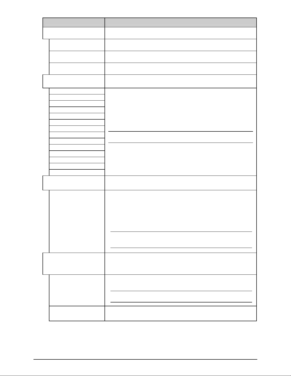
10) Proceed according to the Scan Position:
10-Mil Position: Carefully tighten the Mounting Adjustment
Screw.
Mounting
Adjustment Screw
5-Mil Position: Carefully tighten the Locking Screw on the right
side of the Scanner.
Locking Screw
16
Page 19
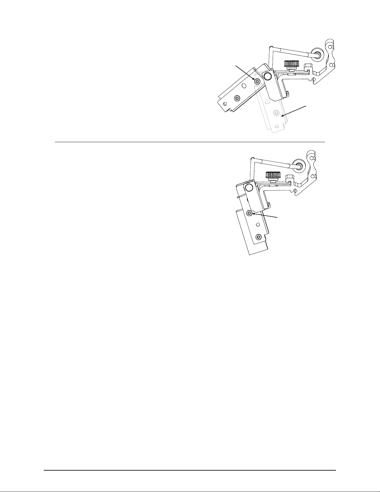
11) Proceed according to the Scan Position:
10-Mil Position: Carefully raise the Pivoting Mount
and then tighten the Locking Screw. Carefully lower
the Pivoting Mount.
5-Mil Position: Carefully tighten the Mounting Adjustment
Locking
Screw
Pivoting
Mount
Screw.
Mounting Adjustment
Screw
17
Page 20

12) Proceed according to the Scan Position:
10-Mil Position: Loosen the
Thumbscrew and slide the Scanner to
the rightmost position on the Mounting
Bracket. Carefully raise the Pivoting
Mount and then tighten the left Locking
Mounting
Bracket
Thumbscrew
Pivoting Mount
Screw. Lower the Pivoting Mount.
Locking Screw
Thumbscrew
Mounting
5-Mil Position: Loosen the Thumbscrew
Bracket
Pivoting Mount
and slide the Scanner to the rightmost
position on the Mounting Bracket.
Tighten the left Locking Screw.
Locking Screw
13) Center the Scanner over the label and tighten the Thumbscrew. Observe the LED (or the SCAN
COUNT) then proceed accordingly:
If the green LED is illuminated (or if the count rapidly increments), go to Step 14.
If the green LED is not illuminated (or if the count does not rapidly increment), restart the
alignment beginning at Step 6.
Note: If using the 5-Mil Scan Position, loosen the Mounting Adjustment Screw and the
Locking Screws before returning to Step 6.
14) Press EXIT. Remove the Print Quality Label and load operating media. Clear faults and position the
labels by pressing FEED. With the printer at READY, print a batch of live labels. If Scanner Faults
occur, re-center and secure the Scanner above the bar code(s); and, if problems persist see
“Troubleshooting.” This completes alignment.
18
Page 21

Scan Resolutions
Capable of scanning 5- or 10-mil symbologies, the scan resolution is determined by the Linear Scanner’s
height above the label surface. Most typically set for a 10-mil resolution, in order to scan 5-mil bar codes,
the scanner must be repositioned then aligned as follows:
Note: In the 5-Mil position, the available scan width is reduced to approximately 3.5 inches (89 mm).
1) Turn OFF and unplug the printer.
2) Loosen the Thumbscrew then slide the Scanner to the rightmost position on the Mounting Bracket.
3) Slightly raise the Pivoting Mount. Remove the Locking Screws, and then lower the Scanner. While
supporting the Scanner in the Pivoting Mount, remove the Mounting Adjustment Screw.
Locking Screws
Mounting
Adjustment Screw
Scanner
Pivoting Mount
4) Align the Scanner to the 5-Mil Position Holes in the Pivoting Mount. Install, but do not tighten, the two
Locking Screws. Install the Mounting Adjustment Screw and tighten it only enough to allow the
Scanner to be positioned for alignment.
Pivoting
Mount
Mounting
Adjustment
Screw
Locking
Screws
5-Mil
Position
Holes
Scanner
5) Center the Scanner over the label and tighten the Thumbscrew. Plug in the Power Cord, and then
proceed to “Alignment.”
19
Page 22

Troubleshooting
Use the table below to locate a description of the symptom that best fits the problem and then find a
corresponding solution.
CAUTION
Note: Press FEED to clear a fault.
No faults are generated when
scanning.
The Linear Scanner contains no user serviceable parts. All product service must be
performed by Datamax-O’Neil. Opening the device will void the warranty and could expose
the hazardous LED light.
Problem Possible solution…
If the barcodes are faulty, the scanner may not be enabled: Ensure that the
MODE is set to Auto, or Enabled; see Operation.
The scanner may be disconnected: Turn OFF the printer. Ensure that the
Connector Cable is attached (look for the red glow at power-up); see Operation.
A Scanner Fault is generated
as soon as printer power is
applied to the printer.
Scanner Faults are
generated, but VOID is not
printed on faulted labels.
Note: Normal if the fault
occurs after a label printed.
Unable to capture feedback
data.
The scanner may be disconnected while Enabled: Turn OFF the printer. Ensure
that the Connector Cable is attached (look for the red glow on power-up); otherwise,
to continue printing without scanning, change the MODE setting to Auto, or
Disabled; see Operation.
Ensure the FAULT HANDLING – LEVEL is set to VOID AND RETRY; see
Operation.
Ensure that sufficient text space exists by adjusting the VOID DISTANCE; see
Operation.
Ensure that OPTION FEEDBACK (Host Settings) is enabled; see Operation.
Depending upon your communication interface, ensure that a bi-directional
cable is being used; see the Operator’s Manual.
If using parallel communications, ensure that BI-DIRECTIONAL
(Communications) is enabled; see the Operator’s Manual.
Depending upon your communication interface, ensure that your host device
settings match those of the printer, and that your software program is set to
parse the received data.
(continued)
20
Page 23

Problem Possible solution…
Scanner Faults are generated
when scanning.
Note:
• Faults are normal when
a bar code has defects,
including insufficient
quiet zones that can
make it unreadable.
• Adjust the HEAT and/or
PRINT SPEED settings
to achieve print quality.
Consult your software
application (or make
changes via the User
Interface; see the
Operator’s Manual for
details).
Try the following –
Examine the print quality of the failed label: If the bar code(s) appear(s) to be
free of voids with sufficient quiet zone space, ensure that the scanner is down,
centered over the labels, and secured with the Thumbscrew.
Dirt or debris could be covering the scanner window: Turn OFF the printer.
Examine the window for obstructions and clean if necessary; see
Maintenance.
The bar codes may be too close together: For multiple-up identical bar codes,
ensure sufficient white space between rows; see Operation.
Ambient lighting could adversely be affecting readability: Reduce / redirect
bright light sources, or increase light in dim areas.
Reflected light off the media may be blinding the optics: Ensure that the label
stock has a matte finish, and not a reflective or glossy surface; see Operation.
The label exit angle may have changed: Ensure that the Tear Bar, Peel
Mechanism, or Rewind Plate has been mounted to the printer and that the
label pathway is unobstructed; see the Operator’s Manual for details.
Current scanner settings may be too restrictive: Try decreasing the MIN
READABLE HEIGHT or REDUNDANCY LEVEL setting, lowering the print
speed, or increasing the height of the bar code; see Operation.
The bar code may not be recognized: Ensure that the symbology is
supported; see Specifications.
The symbology may not be generated by as a font: Bitmapped bar codes or
those containing certain addendums must be specified by number (BAR
CODE COUNT in the menu); see Operation.
The focal length may be incorrect for the bar code resolution: Consult your
software application for the bar code X dimension, and then ensure the scan
position matches and if not change it; see Maintenance.
If problems persist, yet the bar codes are readable on other devices, scanner
misalignment is possible; see Alignment. If you have questions, please contact
Datamax-O’Neil Technical Support.
21
Page 24

Specifications
Physical
Case Material Steel (Black)
Dimensions (L x H x W) 47 x 20 x 55 mm (1.95 x 0.78 x 2.2 in)
Cable Length 7.0 inches with 8 pin Mini DIN connection
Mini DIN Connector
Optical
Scan Rate 700 scans per second ±10%
Wavelength of LED Illumination 660 nanometers
Read Sensor CCD linear array
Narrow Bar Resolution Mounting position dependent: 10-mil or 5-mil
Maximum Character Input 51 digits
Maximum Scanning Width 4.0 inches (101 mm) @ the10-Mil position; and,
Pin Number: Signal:
1 +5 VDC
2 TXD
3 Trigger
4 RTS
5 Signal Ground
6 Chassis Ground
7 RXD
8 CTS
3.5 inches (89 mm) @ the 5-Mil position.
8-pin Mini DIN Connector
MD-80
Minimum Print Contrast Signal 0.45 (min. background reflectance of 70%)
Symbology Orientation Picket fence
Electrical
Operating Voltage +5 VDC + 5%
Current:
Operating 158 mA typical, 220 mA maximum
Static 150 mA maximum
Surge 3 A maximum
Environmental
Temperature:
Operating
Storage
0 to +40 C (+32 to +104 F)
-10 to +60 C (+14 to +140 F)
Humidity (non-condensing):
Operating 20 to 80%
Storage 20 to 90%
Ambient light restrictions: Fluorescent or incandescent: below 5 kilolux
Supported Symbologies*
Codabar (NW-7) Code 39 Code 93
Code 128 Industrial 2 of 5 Interleaved 2 of 5
MSI / Plessey WPC (UPC / EAN / JAN)* IATA
* Bitmapped images and UPC 2 & 5 digit addendums only readable when specified by number in BARCODE COUNT.
22
Page 25

Warranty Information
Warranty Service Procedures
Datamax-O’Neil warrants to Purchaser that under normal use and service, the Scanner purchased
hereunder shall be free from defects in material and workmanship for a period of one year (365 days)
from the date of shipment by Datamax-O’Neil. Expendable and/or consumable items or parts such as
lamps and fuses, are not covered under this warranty. This warranty does not cover equipment or parts
that have been misused, altered, neglected, handled carelessly, or used for purposes other than those for
which they were manufactured. This warranty also does not cover loss, damages resulting from accident,
or damages resulting from unauthorized service.
If a defect should occur during the warranty period, the defective unit shall be returned, freight and
insurance prepaid, in the original shipping container to:
Datamax-O’Neil Corporate Headquarters
4501 Parkway Commerce Boulevard
Orlando, Florida USA 32808
A Return Material Authorization (RMA) number must be issued before the product can be returned. To
open an RMA, please call the Datamax-O’Neil Technical Support Department at (407) 523-5540. Include
your RMA number on the outside of the box and on the shipping document. Include a contact name,
action desired, a detailed description of the problem(s), and media examples when possible with the
defective unit. Datamax-O’Neil shall not be responsible for any loss or damages incurred in shipping. Any
warranty work to be performed by Datamax-O’Neil shall be subject to Datamax-O’Neil’s confirmation that
such product meets Datamax-O’Neil warranty. In the event of a defect covered by its warranty, DatamaxO’Neil will return the repaired or replaced product to the Purchaser at Datamax-O’Neil’s cost.
With respect to a defect in hardware covered by the warranty, the warranty shall continue in effect until
the end of the original warranty period, or for ninety (90) days after the repair or replacement, whichever
is later.
General Warranty Provisions
Datamax-O’Neil makes no warranty as to the design, capability, capacity or suitability of any of its
hardware, supplies, or software.
Software is licensed on an “as is” basis without warranty. Except and to the extent expressly provided in
this warranty and in lieu of all other warranties, there are no warranties, expressed or implied, including,
but not limited to, any warranties of merchantability or fitness for a particular purpose.
Purchaser shall be solely responsible for the selection, use, efficiency and suitability of Datamax-O’Neil’s
products.
Limitation of Liability
In no event shall Datamax-O’Neil be liable to the purchaser for any indirect, special or consequential
damages or lost profits arising out of or relating to Datamax-O’Neil’s products, or the performance or a
breach thereof, even if Datamax-O’Neil has been advised of the possibility thereof. Datamax-O’Neil’s
liability, if any, to the purchaser or to the customer of the purchaser hereunder shall in no event exceed
the total amounts paid to Datamax-O’Neil hereunder by the purchaser for a defective product.
In no event shall Datamax-O’Neil be liable to the purchaser for any damages resulting from or related to
any failure or delay of Datamax-O’Neil in the delivery or installation of the computer hardware, supplies or
software or in the performance of any services.
Some states do not permit the exclusion of incidental or consequential damages, and in those states the
foregoing limitations may not apply. The warranties here give you specific legal rights, and you may have
other legal rights which vary from state to state.
23
Page 26

 Loading...