

Page 1
92-2427-01 Rev.C
GPIO Option
Page 2

Page 3
Overview
This document describes the installation and use of the General Purpose Input Output
(GPIO) option for the H-Class printer. After verifying the kit contents and tools needed,
follow the steps to install and begin using the option.
For safety and to avoid equipment damage, turn OFF the power switch and
CAUTION
unplug the AC power cord from the printer before starting this installation.
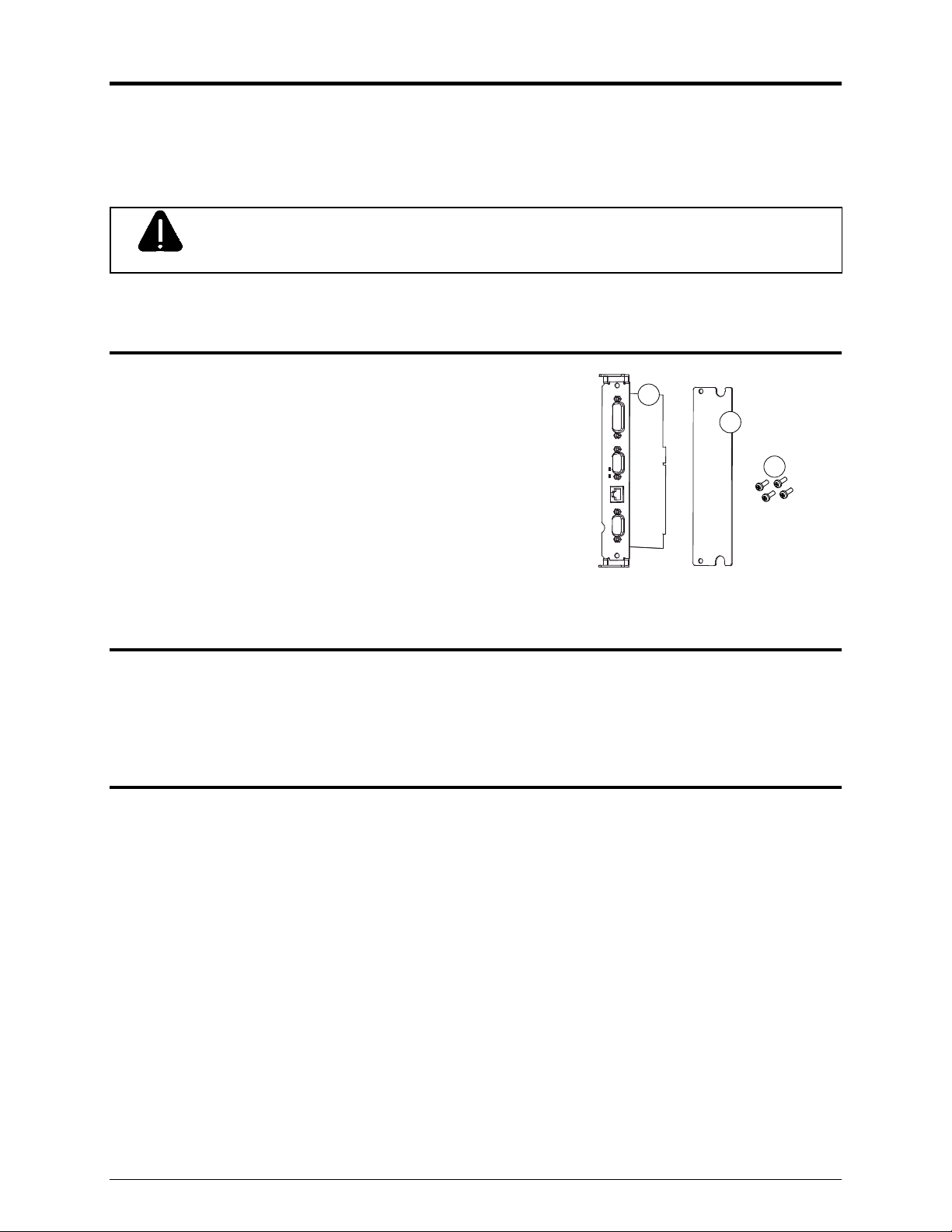
Contents
This kit contains the following items:
GPIO Circuit Card Assembly
Cover Plate
Screws
1
2
3
Tools Required
To install this option, you will need a Philips screwdriv er.
Additional Requirements
Depending on your application, you may need the following hardware to interface the card:
GPI/O A – DB15 Male connector (e.g., StarTech C15PCM) and shielded cabling.
GPI/O B – High Density DB15 Male VGA connector (e.g., StarTech C15HPSM) and
shielded cabling.
COM C – DB9 Male connector (e.g., StarTech C9PSM) and shielded cabling, or a
prefabricated cable (see part numbers and pin out requirements below).
COM D – RJ45 Plug (e.g., Belkin R6G088) and shielded cabling, or a prefabricated
cable (see part number and pin out requirements below).
1
Page 4
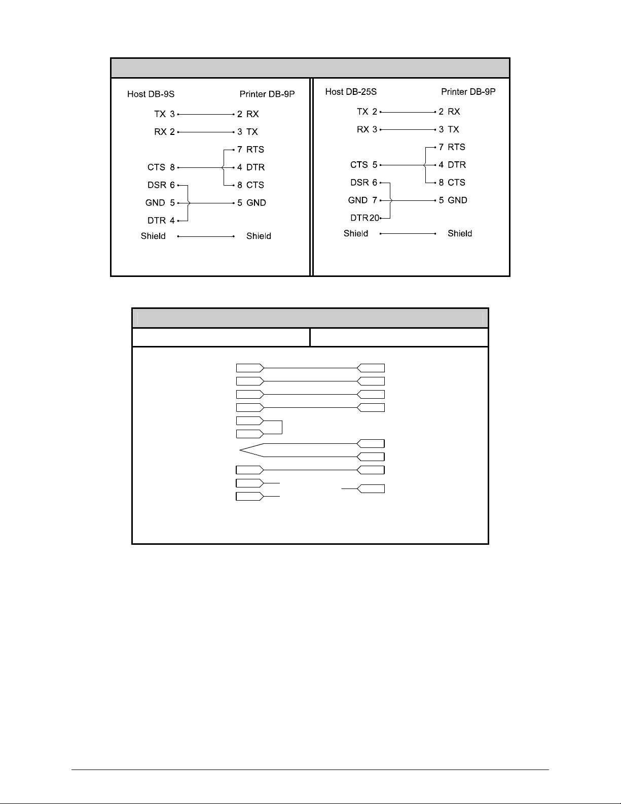
COM C RS-232 Cables
Part # 32-2300-01
Part # 32-2301-01
COM D RS-232 Cable
Host DB-9S Printer RJ45P
+5 VDC
RXD
TXD
GROUND
DTR
DSR
CTS
1
2
3
5
4
6
8
9
7
NC
NC
NC
1
4
5
3
2
7
8
6
+5 VDC
TXD
RXD
GROUND
RTS
CTS
DTR
Part # 32-2603-00
2
Page 5
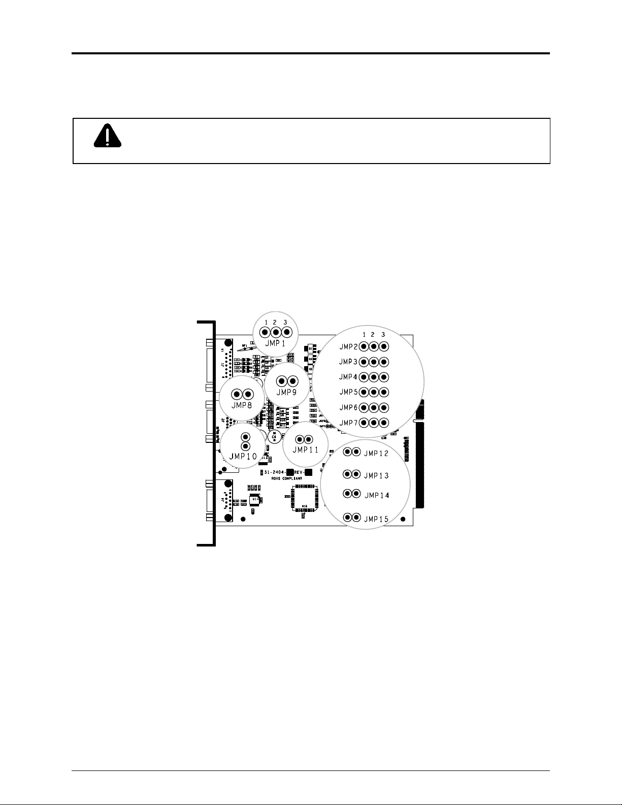
Step 1: Configuring the Hardware
Configure the card to meet your interfacing requirements by arranging hardware jumpers,
as described in the following procedure:
Always wear a wrist strap and follow standard ESD prevention measures
CAUTION
when handling the card.
A) Remove the card from the packaging and then place the card onto a static-free work
area.
B) Set the jumpers on the card (detailed below) to meet the requirements of your
application:
► GPI/O A (J1)
Four dedicated inputs control printer functions. Designed to interface to opencollector outputs, these inputs require no external pu ll-ups, while blocking diodes
allow the use of totem pole outputs from +4.5 VDC to + 26 VDC. Optical isolators
provide galvanic isolation. Two print control interface circuit examples are given
below.
3
Page 6

For direct inputs –
Use the printer’s +5VDC and Ground to supply
the devices interfacing to the GPI/O A inputs
(as shown in the sample circuit, right).
For isolated inputs –
To provide galvanic isolation for the GPI/O A
inputs, remove Jumper JMP 9 then supply an
external +5VDC source voltage to Pin 2, and
remove Jumper JMP 8 then supply an external
Ground to Pin 1 (as shown this sample circuit,
right).
+5 VDC External Source
GPI/O A - J1
Start of Print
3
Slew Label
4
Toggle/Pause
5
Reprint
6
Ground
1
GPI/O A - J1
2
Vcc
3
Start of Print
4
Slew Label
5
Toggle/Pause
6
Reprint
Ground
1
Seven dedicated outputs are available for control, warning, and error functions.
These open-collector outputs have slew-limited signal-edge rise and fall times to
prevent cross talk in the cabling. Optional 10K ohm pull-up resistors, tied to a
common point for use at either +5 or +24 VDC, are available via Jumper JMP 1.
Note: If external pull-ups are used (that is, without Jumper JMP1 installed),
ensure that the applied external voltage does not exceed +30VDC.
The table below details the GPI/O A pin assignments, settings and functions.
4
Page 7

Failure to properly configure the GPIO Port can result in damage to the printer and / or connected devices.
WARNING
Pin
1
2 +5 VDC
3 Start Of Print
4 Slew Label
5 Toggle / Pause The printer pauses when the signal is taken LOW.
6 Reprint
7 +24 VDC Printer +24 VDC (1.5 amp maximum).
8 Ground
9 Ribbon Low Programmable
10 Service Required Evoked by occurrences listed under ‘Fault Messages.’
11 End Of Print Programmable
12 Media Out Evoked during an Out of Stock condition. Active LOW.
13 Ribbon Out Evoked during an Out of Ribbon condition. Active LOW.
14 Data Ready
15 Option Fault
[1]
Signal directions given relative to the printer.
[2]
If active with no current print job, “WAITING FOR DATA” will be displayed. Specifying a quantity of 9999 while keeping this signal ON will cause non-stop label printing, except
in single label “Imaging Mode”, which will cause the printer to stop between labels. See the Operator’s Manual for details.
[3]
For details see PRINTER OPTIONS / GPIO PORT in the Operator’s Manual.
Signal
Name
Ground
GPI/O Port A Jumper Overview
Direction
JMP 8
[1]
Jumper
Position Function / Description
Installed Printer chassis is used.
Removed Ground must be supplied.
N/A
JMP 9
Installed
Printer +5VDC is used (.5 amp maximum)
Note: Drawing more than .5 amps can cause unreliable printer operation.
Removed +5VDC must be supplied.
[2]
Programmable
Media is advanced until the signal goes HIGH and, if not in continuous mode, the label
is positioned at the next available TOF.
Input
N/A N/A
The last label is reprinted exactly, with no increment or time stamp changes;
recommended for use during error conditions. Keeping this signal LOW produces nonstop printing.
N/A
Printer chassis.
When inactive, outputs will be
pulled up to a voltage
determined by this jumper
setting, where:
Output JMP 1
Pins 1 – 2 = +5VDC;
Pins 2 – 3 = +24VDC; or,
None = an external voltage
(not to exceed +30VDC) via
external pull-ups providing a
20K ohm feedback path
through any two outputs.
Evoked when a label is waiting to print. After Start of Print is received, printing will begin.
For synchronization with the print cycle, End Of Print indicates the completion of the
process. Active LOW.
Evoked during a Linear Scanner or RFID fault condition. Active LOW.
[3]
[1]
. Signifies a RIBBON LOW DIAMETER warning condition.
[1]
Active LOW.
[1]
. Signifies the End of Print (EOP) process.
5
Page 8

► GPI/O B (J2)
Six unassigned inputs are designed to interface to open-collector outputs. These
inputs require no external pull-ups, while blockin g diodes allow the use of totem pole
outputs from +4.5 VDC to + 26 VDC. Optical isolators provide galvanic isolation. Two
print control interface circuit examples are given below.
For direct inputs:
Use the printer’s +5VDC to supply the devices
interfacing to the GPI/O B inputs (as shown in
the sample circuit, right).
+5 VDC External Source
For isolated inputs:
To provide galvanic isolation for the GPI/O B
inputs, remove Jumper JMP 11 then supply an
external +5VDC source voltage to Pin 1, and
remove Jumper JMP 10 then supply an
external Ground to Pin 6 (as shown in the
sample circuit, right).
13
8
3
12
7
2
6
1
13
8
3
12
7
2
6
GPI/O B - J2
Input 1
Input 2
Input 3
Input 4
Input 5
Input 6
Ground
GPI/O B - J2
Vcc
Input 1
Input 2
Input 3
Input 4
Input 5
Input 6
Ground
Six unassigned outputs have slew-limited signal-edge rise and fall times to
prevent cross talk in the cabling. Optional 10K ohm pull-up resistors, one for each of
the output lines, can be used at either +5 or +24 VDC via Jumpers JMP 2 – 7.
Note: If external pull-ups are employed (that is, when Jumpers JMP 2 - 7 are
not installed), ensure that the applied external voltage does not exceed
+30VDC.
The table below details the GPI/O B pin assignments, settings and functions.
6
Page 9

Failure to properly configure the GPIO Port can result in damage to the printer and / or connected devices.
WARNING
Pin Signal Name / Direction
1
2 Input 6 N/A N/A Programmed input function.
3 Input 3 N/A N/A Programmed input function.
4 Output 6 JMP 7
5 Output 3 JMP 4
6 Ground JMP 10
7 Input 5 N/A N/A Programmed input function.
8 Input 2 N/A N/A Programmed input function.
9 Output 5 JMP 6
10 Output 2 JMP 3
11 +24 VDC N/A N/A Printer +24 VDC (1.5 amp maximum).
12 Input 4 N/A N/A Programmed input function.
13 Input 1 N/A N/A Programmed input function.
14 Output 4 JMP 5
15 Output 1 JMP 2
[1]
Signal directions given relative to the printer.
GPI/O Port B Overview
[1]
Jumper Position Function / Description
Printer +5VDC is used (.5 amp maximum).
+5 VDC JMP 11
Installed
Note: Drawing more than .5 amps can cause unreliable printer operation.
Removed +5VDC must be supplied.
Installed: Pins 1 – 2 Programmed output function pulled-up to +5VDC.
Installed: Pins 2 – 3 Programmed output function pulled-up to +24VDC.
Removed An external voltage via external pull-ups will determine this level, not exceed +30VDC.
Installed: Pins 1 – 2 Programmed output function pulled-up to +5VDC.
Installed: Pins 2 – 3 Programmed output function pulled-up to +24VDC.
Removed An external voltage via external pull-ups will determine this level, not exceed +30VDC.
Installed Printer chassis is used.
Removed Ground must be supplied.
Installed: Pins 1 – 2 Programmed output function pulled-up to +5VDC.
Installed: Pins 2 – 3 Programmed output function pulled-up to +24VDC.
Removed An external voltage via external pull-ups will determine this level, not exceed +30VDC.
Installed: Pins 1 – 2 Programmed output function pulled-up to +5VDC.
Installed: Pins 2 – 3 Programmed output function pulled-up to +24VDC.
Removed An external voltage via external pull-ups will determine this level, not exceed +30VDC.
Installed: Pins 1 – 2 Programmed output function pulled-up to +5VDC.
Installed: Pins 2 – 3 Programmed output function pulled-up to +24VDC.
Removed An external voltage via external pull-ups will determine this level, not exceed +30VDC.
Installed: Pins 1 – 2 Programmed output function pulled-up to +5VDC.
Installed: Pins 2 – 3 Programmed output function pulled-up to +24VDC.
Removed An external voltage via external pull-ups will determine this level, not exceed +30VDC.
7
Page 10
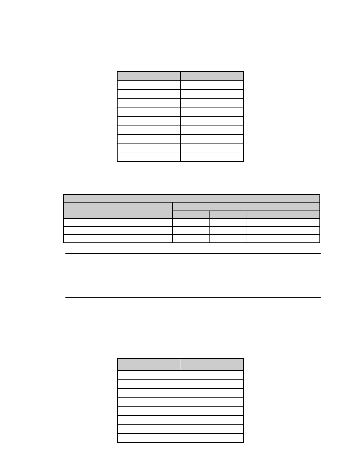
► COM C (J4)
Recognized by the printer as Serial Port C, COM C functions as an auxiliary RS-232
interface or dedicated device port for the RFID and Linear Scanner options. Pin
assignments for the port are as follows:
Pin Number COM C (J4)
1 +5V (@ .5 amps)
2 RX
3 TX
4 DTR
5 Ground
6 Ground
7 RTS
8 CTS
9 N/C
At default settings, the COM C port automatically selects its function. To force a
selection, however, change the jumper settings as denoted in the table below:
COM C Jumper Setting Functions
Selected Function
RS-232 Communications (default)
RFID Off On On On
Linear Scanner On Off On On
JMP 12 JMP 13 JMP 14 JMP 15
On On On On
Jumper and Setting
Note: Jumper settings override menu settings: If set for RS-232 (default) with
the RFID and Linear Scanner menu-enabled, the printer will assign RFID to
Serial Port B (back plane port J13) and the Linear Scanner to the COM C
port.
► COM D (J3)
Recognized by the printer as Serial Port D, COM D is an auxiliary RS-232 interface.
Pin assignments for the port are as follows:
Pin Number COM D (J3)
1 +5V (@ .5 amps)
2 RTS
3 Ground
4 TX
5 RX
6 Ground
7 CTS
8 DTR
8
Page 11

Step 2: Installing the Option
Install the GPIO Card as described below:
A) Turn OFF the Power Switch and
unplug the power cord from the AC
Receptacle.
B) Remove the two Screws that secure
the Back Panel to the Card Cage,
and then remove the Back Panel.
C) Slide the GPIO Card (Item 1),
Screws
Card Cage
Slot
Power Switch
AC Receptacle
Card Cage
Back Panel
GPIO Card
Notch down, into the leftmost Card
Cage Slot. Firmly push the GPIO
Card to seat it and then secure the
card using the two Screws (Item 3).
Screws
Notch
9
Page 12

D) Place the Cover Plate (Item 2) onto
the Card Cage, as shown, then
install and tighten the two Screws
(Item 3) to secure the plate.
Card Cage
Cover Plate
Screws
Step 3: Interfacing
Interface the card according to your application requirements (see the drawing below for
connector pin-outs, refer to Step 1 for signal details) as follows:
8
15
7
14
6
13
5
12
11
10
9
J2
15
14
13
12
11
10
5
4
9
3
8
2
7
1
6
5
9
4
8
J4
3
7
2
6
1
A) For GPIO functions connect a GPI/O interface cable to the GPI/O A (J1) and / or GPI/O
J1
4
3
2
1
1
J3
8
B (J2) ports.
B) For RS232 communications connect a serial interface cable to COM C (J4) and / or COM
D (J3); for dedicated devices, connect the cabling from that device to COM C (J4).
Note: If using both the RFID and Linear Scanner, see Configuring Hardware
Settings, above.
C) Connect the AC power cord to the printer and then turn the power switch ON.
10
Page 13

Step 4: Configuring the Software Settings
Configure the printer’s m
A) Using the Control Panel, enter the ADVANCED MENU (see the Operator’s Manual for
menu navigation details):
• If using the GPIO A (J1) port, configure the settings to meet the requirements of
your system using the PRINTER OPTIONS GPIO PORT APPLICATOR
menu selection;
• If using the GPIO B (J2) port, refer to your MCL documentation;
• If using the COM C (J4) port for serial communications, configure the it to meet the
requirements of your host system’s serial port settings using the
COMMUNICATIONS SERIAL PORT C menu selection; or,
If using the COM C (J4) port for a dedicated device, enable that device using the
enu settings for the option’s operation.
PRINTER OPTIONS menu selection; and,
• If using the COM D (J3) port for serial communications, configure the port to meet
the requirements of your host system’s serial port settings using the
COMMUNICATIONS SERIAL PORT D menu selection.
B) After entering the desired settings exit the menu system and save your changes. The
printer is now ready to operate using the GPIO option.
Verifying Setup and Operation
Verification of the settings and active monitoring is provided:
Indicators – View incoming (IN) and outgoing (OUT)
signal activity via the card bracket. Sampled every
millisecond, these LED indicators change color as incoming
or outgoing GPIO signals change state.
11
Signal In
Signal Out
Page 14

Input Monitor – Display incoming GPIO binary signal states using the ADVANCED
MENU DIAGNOSTICS OPTIONS TESTING TEST GPIO MONITOR GPIO
INPUT selection.
GPIO A
Signals
SOP FEED PAUSE REPRT
1 1 0 0
i1 i2 i3 i4 i5 i6
0 1 0 1 1 1
GPIO B
Signals
Note: Unused, non-connected inputs will have an indeterminate state, and may
assume a value of 1 or 0.
Output Monitor – Display outgoing GPIO binary signal states using the ADVANCED
MENU DIAGNOSTICS OPTIONS TESTING TEST GPIO MONITOR GPIO
OUTPUT selection.
GPIO A
Signals
EP RL SR MO RO DR OF
0 0 0 0 0 0 0
o1 o2 o3 o4 o5 o6
0 0 0 0 0 0
GPIO B
Signals
Note: Unused, non-connected outputs will have an indeterminate state, and may
assume a value of 1 or 0.
GPIO Report – Print the configuration and current signal state information using the
ADVANCED MENU / DIAGNOSTICS / OPTIONS TESTING / TEST GPIO / PRINT
SIGNAL INFO selection:
GPIO SIGNAL INFO
WED 11:04AM 4JUL2005
CARD ID#3
OUTPUT SIGNALS
END OF PRINT
PIN# 11 GPIO A
LOW PULSE
CURRENT LEVEL 1
RIBBON LOW
PIN# 9 GPIO A
ACTIVE LOW
CURRENT LEVEL 0
SERVICE REQUIRED
PIN# 10 GPIO A
ACTIVE LOW
CURRENT LEVEL 1
MEDIA OUT
PIN# 12 GPIO A
ACTIVE LOW
CURRENT LEVEL 1
RIBBON OUT
PIN# 13 GPIO A
ACTIVE LOW
CURRENT LEVEL 1
DATA READY
PIN# 14 GPIO A
ACTIVE LOW
CURRENT LEVEL 1
OPTION FAULT
PIN# 15 GPIO A
ACTIVE LOW
CURRENT LEVEL 1
o1
PIN# 15 GPIO B
CURRENT LEVEL 1
o2
PIN# 10 GPIO B
CURRENT LEVEL 0
o3
PIN# 5 GPIO B
CURRENT LEVEL 1
o4
PIN# 14 GPIO B
CURRENT LEVEL 1
o5
PIN# 9 GPIO B
CURRENT LEVEL 1
o6
PIN# 4 GPIO B
CURRENT LEVEL 1
INPUT SIGNALS
START OF PRINT
PIN# 3 GPIO A
ACTIVE HIGH
CURRENT LEVEL 1
FEED
PIN# 4 GPIO A
ACTIVE LOW
CURRENT LEVEL 1
TOGGLE PAUSE
PIN# 5 GPIO A
ACTIVE LOW
CURRENT LEVEL 1
REPRINT
PIN# 6 GPIO A
ACTIVE LOW
CURRENT LEVEL 1
i1
PIN# 13 GPIO B
CURRENT LEVEL 1
i2
PIN# 8 GPIO B
CURRENT LEVEL 0
i3
PIN# 3 GPIO B
CURRENT LEVEL 1
i4
PIN# 12 GPIO B
CURRENT LEVEL 1
i5
PIN# 7 GPIO B
CURRENT LEVEL 1
i6
PIN# 2 GPIO B
CURRENT LEVEL 1
12
 Loading...