

Page 1
Operator’s Manual
l
l
+
Professional and Professional+ Models
Professiona
Professiona
Page 2

Page 3

Copyright Information
CG Triumvirate is a trademark of Agfa Corporation.
CG Times based upon Times New Roman under license from the Monotype Corporation.
Windows is a registered trademark of the Microsoft Corporation.
All other brand and product names are trademarks, service marks, registered trademarks, or registered service
marks of their respective companies.
Limitation of Liability
In no event shall Datamax-O’Neil be liable to the purchaser for any indirect, special or consequential damages or
lost profits arising out of or relating to Datamax-O’Neil’s products, or the performance or a breach thereof, even
if Datamax-O’Neil has been advised of the possibility thereof. Datamax-O’Neil’s liability, if any, to the purchaser
or to the customer of the purchaser hereunder shall in no event exceed the total amounts paid to DatamaxO’Neil hereunder by the purchaser for a defective product.
In no event shall Datamax-O’Neil be liable to the purchaser for any damages resulting from or related to any
failure or delay of Datamax-O’Neil in the delivery or installation of the computer hardware, supplies or software
or in the performance of any services.
Some states do not permit the exclusion of incidental or consequential damages, and in those states the
foregoing limitations may not apply. The warranties here give you specific legal rights, and you may have other
legal rights which vary from state to state.
Firmware (Software) Agreement
The enclosed Firmware (Software) resident in the Printer is owned by Licensor or its suppliers and is licensed for
used only on a single printer in the user’s Trade or Business. The User agrees not to, and not to authorize
or permit any other person or party to, duplicate or copy the Firmware or the information contained
in the non-volatile or programmable memory. The firmware (Software) is protected by applicable copyright
laws and Licensor retains all rights not expressly granted. In no event will Licensor or its suppliers be liable for
any damages or loss, including direct, incidental, economic, special, or consequential damages, arising out of
the use or inability to use the Firmware (Software).
Information in this document is subject to change without notice and does not represent a commitment on the
part of Datamax-O’Neil Corporation. No part of this manual may be reproduced or transmitted in any form or by
any means, for any purpose other than the purchaser's personal use, without the expressed written permission
of Datamax-O’Neil Corporation.
Important Safety Instructions
This printer has been carefully designed to provide years of safe reliable performance. As with all types of
electrical equipment, however, there are a few basic precautions that should be taken to avoid personal
injury or damage to the device:
• Carefully read the installation and operating instructions provided with the printer.
• Read and follow all warning and instruction labels on the printer.
• Place the printer on a flat, stable surface.
• Do not insert anything into the ventilation slots or openings on the printer.
• Do not place the printer on or near a heat source.
• Do not use the printer near water. Never spill liquid into the printer.
• Be certain the power source is within the voltage rating and frequency listed for the printer. If you are unsure,
check with your dealer, an electrician, or local power company.
• Do not place the power cord where it can be stepped on. If the power cord becomes damaged or frayed,
replace it immediately.
• Only qualified, trained service technicians should attempt to repair the printer.
Cut-outs are not intended for wall-mount use.
Page 4
Agency Compliance and Approvals
C US
Listed
FCC: This device complies with FCC CFR 47 Part 15 Class A.
Note: This equipment has been tested and found to comply with the limits for a Class A digital
UL60950-1, Second Edition, Information Technology Equipment
CSA C22.2 No. 60950-1-03, Second Edition
The manufacturer declares under sole responsibility that this product conforms to the
following standards or other normative documents:
EMC: EN 55022 (2006) Class A
EN 50024 (1998)
IEC 60950-1 :2001, Second Edition
Safety: This product complies with the requirements of IEC 60950-1:2001, Second Edition
Gost-R
GB4943-2001, GB9254-1998, GB17625.1-2003
device, pursuant to Part 15 of the FCC Rules. These limits are designed to provide
reasonable protection against harmful interference when the equipment is operated in a
commercial environment. This equipment generates, uses, and can radiate radio
frequency energy, and if not installed and used in accordance with the instructions in
this manual, it may cause harmful interference to radio communications. Operation of
this equipment in a residential area is likely to cause harmful interference in which case
the user will be required to correct the interference at his own expense.
All rights reserved
Copyright © 2013, Datamax-O’Neil
Part Number: 88-2358-01, Rev B
Page 5

s
t
n
e
t
n
o
C
C
C
1
G
1
G
1
G
1.1 Introduction ........................................................................................................ 1
1.2 Unpacking the Printer ........................................................................................... 1
1.3 Kensington Security Slot ....................................................................................... 2
2
P
2
P
2
P
2.1 Introduction ........................................................................................................ 3
2.2 Connecting the Printer .......................................................................................... 3
2.3 Loading Media...................................................................................................... 5
n
o
n
o
e
t
t
i
n
e
r
r
r
g
t
t
i
n
e
g
t
t
i
n
g
i
n
t
e
r
i
n
t
e
r
i
n
t
e
r
2.2.1
2.2.2 Interface Connections ................................................................................. 4
e
t
e
t
S
t
a
r
t
e
S
t
S
t
S
e
S
e
S
e
Power Connections ..................................................................................... 3
d
a
r
t
e
a
r
t
e
t
u
p
.
t
u
p
.
t
u
p
.
n
n
.
.
d
.
.
d
.
.
.
.
.
.
.
.
.
.
.
.
t
t
.
.
.
.
.
.
.
.
.
.
.
.
.
.
.
.
.
.
.
.
.
.
.
.
.
.
.
.
.
.
.
.
.
.
.
.
.
.
s
s
.
.
.
.
.
.
.
.
.
.
.
.
.
.
.
.
.
.
.
.
.
.
.
.
.
.
.
.
.
.
.
.
.
.
.
.
.
.
.
.
.
.
.
.
.
.
.
.
.
.
.
.
.
.
.
.
.
.
.
.
.
.
.
.
.
.
.
.
.
.
.
.
.
.
.
.
.
.
.
.
.
.
.
.
.
.
.
.
.
.
.
.
.
.
.
.
.
.
.
.
.
.
.
.
.
.
.
.
.
.
.
.
.
.
.
.
.
.
.
.
.
.
.
.
.
.
.
.
.
.
.
.
.
.
.
.
.
.
.
.
.
.
.
.
.
.
.
.
.
.
.
.
.
.
.
.
.
.
.
.
.
.
.
.
.
.
.
.
.
.
.
.
.
.
.
.
.
.
.
.
.
.
.
.
.
.
.
.
.
.
.
.
.
.
.
.
.
.
.
.
.
.
.
.
.
.
.
.
.
.
.
.
.
.
.
.
.
.
.
.
.
.
.
.
.
.
.
.
.
.
.
.
.
.
.
.
.
.
.
.
.
.
.
.
.
.
.
.
.
.
.
.
.
.
.
.
.
.
.
.
.
.
.
.
.
.
.
.
.
.
.
.
.
.
.
.
.
.
.
.
.
.
.
.
.
.
.
.
.
.
.
.
.
.
.
.
.
.
.
.
.
.
.
.
.
.
.
.
.
.
.
.
.
.
.
.
.
.
.
.
.
.
.
.
.
.
.
.
.
.
.
.
.
.
.
.
.
.
.
.
.
.
.
.
.
.
.
.
.
.
.
.
.
.
.
.
.
.
.
.
.
.
.
.
.
.
.
.
.
.
.
.
.
.
.
.
.
.
.
.
.
.
.
.
.
.
.
.
.
.
.
.
.
.
.
.
.
.
.
.
.
.
.
.
.
.
.
.
.
.
.
.
.
.
.
.
.
.
.
.
.
.
.
.
.
.
.
.
.
.
.
1
.
.
.
.
.
.
.
.
.
.
.
.
.
.
.
.
.
.
1
.
.
.
.
.
1
.
.
.
.
3
.
.
.
.
.
3
.
.
.
.
.
3
Loading Roll Media...................................................................................... 5
2.3.1
2.3.2 Loading - External Media ............................................................................. 7
2.3.3 Loading Media with the Peel and Present Option.............................................. 9
2.3.4 Loading Media with the Cutter Option.......................................................... 10
2.3.5 Adjustable Media Core Hangers (Pro+ models only)....................................... 11
2.4 Loading Ribbon .................................................................................................. 12
Using the Ribbon Core Adapters ................................................................. 15
2.4.1
3
P
r
i
n
t
e
r
O
p
e
r
a
t
i
o
n
.
.
.
.
.
.
.
.
.
.
.
.
.
.
.
.
.
.
.
.
.
.
.
.
.
.
.
.
.
.
.
.
.
.
.
.
.
.
.
.
.
.
.
.
.
.
.
.
.
.
.
.
.
.
.
.
.
.
.
.
.
.
.
.
.
.
.
.
.
.
.
.
.
.
.
3
P
r
i
n
t
e
r
O
p
e
r
a
t
i
o
n
.
.
.
.
.
.
.
.
.
.
.
.
.
.
.
.
.
.
.
.
.
.
.
.
.
.
.
.
.
.
.
.
.
.
.
.
.
.
.
.
.
.
.
.
.
.
.
.
.
.
.
.
.
.
.
.
.
.
.
.
.
.
.
.
.
.
.
3
P
r
i
n
t
e
r
O
p
e
r
a
t
i
o
n
.
.
.
.
.
.
.
.
.
.
.
.
.
.
.
.
.
.
.
.
.
.
.
.
.
.
.
.
.
.
.
.
.
.
.
.
.
.
.
.
.
.
.
.
.
.
.
.
.
.
.
.
.
.
.
.
.
.
.
.
3.1 Introduction ...................................................................................................... 17
3.2 LED Indicators ................................................................................................... 17
3.3 User Interface.................................................................................................... 18
Feed/Pause Mode ..................................................................................... 18
3.3.1
3.3.2 Test Mode ............................................................................................... 18
3.3.3 Menu Mode.............................................................................................. 19
3.4 Printer Configuration Tools .................................................................................. 20
.
.
.
.
.
.
.
.
.
.
.
.
.
.
.
.
.
.
.
.
.
.
.
.
.
.
.
.
.
.
1
7
.
.
.
.
.
.
.
.
1
7
.
.
.
1
7
Printer Configuration Utility (NETira CT)................................................................. 21
3.5
3.6 Windows Driver.................................................................................................. 24
3.7 Media Calibration ............................................................................................... 26
3.7.1 Quick Calibration...................................................................................... 26
3.7.2 Manual Calibration.................................................................................... 27
3.7.3 Advanced Entry Calibration........................................................................ 28
i
Page 6

4
M
e
n
u
S
y
s
t
e
m
.
.
.
.
.
.
.
.
.
.
.
.
.
.
.
.
.
.
.
.
.
.
.
.
.
.
.
.
.
.
.
.
.
.
.
.
.
.
.
.
.
.
.
.
.
.
.
.
.
.
.
.
.
.
.
.
.
.
.
.
.
.
.
.
.
.
.
.
.
.
.
.
.
.
.
.
.
.
.
.
.
4
M
e
n
u
S
y
s
t
e
m
.
.
.
.
.
.
.
.
.
.
.
.
.
.
.
.
.
.
.
.
.
.
.
.
.
.
.
.
.
.
.
.
.
.
.
.
.
.
.
.
.
.
.
.
.
.
.
.
.
.
.
.
.
.
.
.
.
.
.
.
.
.
.
.
.
.
.
.
.
.
.
.
.
4
M
e
n
u
S
y
s
t
e
m
.
.
.
.
.
.
.
.
.
.
.
.
.
.
.
.
.
.
.
.
.
.
.
.
.
.
.
.
.
.
.
.
.
.
.
.
.
.
.
.
.
.
.
.
.
.
.
.
.
.
.
.
.
.
.
.
.
.
.
.
.
.
.
.
.
.
4.1 Menu System Overview....................................................................................... 35
4.2 The User Menu................................................................................................... 35
4.3 The Advanced Menu............................................................................................ 36
4.4 Menu Details ..................................................................................................... 37
5
M
a
i
n
t
e
n
a
n
c
e
&
A
d
j
u
s
t
m
e
n
t
s
.
.
.
.
.
.
.
.
.
.
.
.
.
.
.
.
.
.
.
.
.
.
.
.
.
.
.
.
.
.
.
.
.
.
.
.
.
.
.
.
.
.
.
5
M
a
i
n
t
e
n
a
n
c
e
&
A
d
j
u
s
t
m
e
n
t
s
.
.
.
.
.
.
.
.
.
.
.
.
.
.
.
.
.
.
.
.
.
.
.
.
.
.
.
.
.
.
.
.
.
.
.
5
M
a
i
n
t
e
n
a
n
c
e
&
A
d
j
u
s
t
m
e
n
t
s
.
.
.
.
.
.
.
.
.
.
.
.
.
.
.
.
.
.
.
.
.
.
.
.
.
.
.
.
5.1 Introduction ...................................................................................................... 51
5.2 Cleaning the Printhead........................................................................................ 52
5.3 Ribbon Tension Adjustment ................................................................................. 54
5.4 Adjustable Media Sensor ..................................................................................... 55
5.5 Printhead Replacement ....................................................................................... 56
5.6 Platen Roller Replacement ................................................................................... 58
5.7 Updating Firmware ............................................................................................. 59
.
.
.
.
.
.
.
.
.
.
.
.
.
.
.
.
.
.
.
.
.
.
.
.
.
.
.
.
.
.
.
.
.
.
.
.
.
.
.
.
.
.
.
.
.
.
.
.
.
.
.
.
.
.
.
.
.
.
.
.
.
.
.
.
.
.
.
.
.
.
.
.
.
.
.
.
.
.
.
.
.
.
.
.
.
.
.
.
.
.
.
.
.
.
.
.
.
.
3
5
.
.
.
.
.
.
.
.
.
.
.
.
.
.
.
.
.
.
3
5
.
.
.
3
5
.
.
5
1
.
.
.
5
1
.
.
.
5
1
5.7.1 Boot 1 and Boot 2 Boot Loaders.................................................................. 59
6
T
r
o
u
b
l
e
s
h
o
o
t
i
n
g
.
.
.
.
.
.
.
.
.
.
.
.
.
.
.
.
.
.
.
.
.
.
.
.
.
.
.
.
.
.
.
.
.
.
.
.
.
.
.
.
.
.
.
.
.
.
.
.
.
.
.
.
.
.
.
.
.
.
.
.
.
.
.
.
.
.
.
.
.
.
.
.
.
.
.
.
6
T
r
o
u
b
l
e
s
h
o
o
t
i
n
g
.
.
.
.
.
.
.
.
.
.
.
.
.
.
.
.
.
.
.
.
.
.
.
.
.
.
.
.
.
.
.
.
.
.
.
.
.
.
.
.
.
.
.
.
.
.
.
.
.
.
.
.
.
.
.
.
.
.
.
.
.
.
.
.
.
.
.
.
6
T
r
o
u
b
l
e
s
h
o
o
t
i
n
g
.
.
.
.
.
.
.
.
.
.
.
.
.
.
.
.
.
.
.
.
.
.
.
.
.
.
.
.
.
.
.
.
.
.
.
.
.
.
.
.
.
.
.
.
.
.
.
.
.
.
.
.
.
.
.
.
.
.
.
.
.
6.1 Introduction ...................................................................................................... 61
6.2 Troubleshooting Tips........................................................................................... 61
6.3 Hex Dump Mode ................................................................................................ 63
A
S
p
e
c
i
f
i
c
a
t
i
o
n
s
.
.
.
.
.
.
.
.
.
.
.
.
.
.
.
.
.
.
.
.
.
.
.
.
.
.
.
.
.
.
.
.
.
.
.
.
.
.
.
.
.
.
.
.
.
.
.
.
.
.
.
.
.
.
.
.
.
.
.
.
.
.
.
.
.
A
S
p
e
c
i
f
i
c
a
t
i
o
n
s
.
.
.
.
.
.
.
.
.
.
.
.
.
.
.
.
.
.
.
.
.
.
.
.
.
.
.
.
.
.
.
.
.
.
.
.
.
.
.
.
.
.
.
.
.
.
.
.
.
.
.
.
.
.
.
.
.
A
S
p
e
c
i
f
i
c
a
t
i
o
n
s
.
.
.
.
.
.
.
.
.
.
.
.
.
.
.
.
.
.
.
.
.
.
.
.
.
.
.
.
.
.
.
.
.
.
.
.
.
.
.
.
.
.
.
.
.
.
.
.
.
.
B
W
i
r
e
l
e
s
s
a
n
d
W
i
r
e
d
L
A
N
S
e
t
u
p
.
.
.
.
.
.
.
.
.
.
.
.
.
.
.
.
.
.
.
.
.
.
.
.
B
W
i
r
e
l
e
s
s
a
n
d
W
i
r
e
d
L
A
N
S
e
t
u
p
.
.
.
.
.
.
.
.
.
.
.
.
.
.
.
.
B
W
i
r
e
l
e
s
s
a
n
d
W
i
r
e
d
L
A
N
S
e
t
u
p
.
.
.
.
.
.
.
.
.
B.1 Network Card Setup ........................................................................................... 69
B.2 Wireless Setup................................................................................................... 70
B.2.1 Wireless Setup – Infrastructure.................................................................. 71
B.2.1 Wireless Setup – Ad-Hoc ........................................................................... 72
B.3 Installing the Printer Driver.................................................................................. 74
C
B
l
u
e
t
o
o
t
h
S
e
t
u
p
.
.
.
.
.
.
.
.
.
.
.
.
.
.
.
.
.
.
.
.
.
.
.
.
.
.
.
.
.
.
.
.
C
C
B
l
u
e
t
o
o
t
h
S
e
t
u
p
.
.
.
.
.
.
.
.
.
.
.
.
.
.
.
.
.
.
.
.
.
.
.
.
B
l
u
e
t
o
o
t
h
S
e
t
u
p
.
.
.
.
.
.
.
.
.
.
.
.
.
.
.
.
.
.
.
.
.
.
.
.
.
.
.
.
.
.
.
.
.
.
.
.
.
.
.
.
.
.
.
.
.
.
.
.
.
.
.
.
.
.
.
.
.
.
.
.
.
.
.
.
.
.
.
.
.
.
.
.
.
.
.
.
.
.
.
.
.
.
.
.
.
.
.
.
.
.
.
.
.
.
.
.
.
.
.
.
.
.
.
.
.
.
.
.
.
.
.
.
.
.
.
.
.
.
.
.
.
.
.
.
.
.
.
.
.
.
.
.
.
.
.
.
.
.
.
.
.
.
.
.
.
.
.
.
.
.
.
.
.
.
.
.
.
.
.
.
.
.
.
.
.
.
.
.
.
.
.
.
.
.
.
.
.
.
.
.
.
.
.
.
.
.
.
.
.
.
.
.
.
.
.
.
.
.
.
.
.
.
.
.
.
.
.
.
.
.
.
.
.
.
.
.
.
.
.
.
.
.
.
.
.
.
.
.
.
.
.
.
.
.
.
.
.
.
.
.
.
.
.
.
.
.
.
.
.
.
.
.
.
.
.
.
.
.
.
.
.
.
.
.
.
.
.
.
.
.
.
.
.
.
.
.
.
.
.
.
.
.
.
.
.
.
.
.
.
.
.
.
.
.
.
.
.
.
.
.
.
.
.
.
.
.
.
.
.
.
.
.
.
.
.
.
.
.
.
.
.
.
.
.
.
.
.
.
.
.
.
.
.
.
.
.
.
.
.
.
.
.
.
.
.
.
.
.
.
.
.
.
.
.
.
.
.
.
.
.
.
.
.
.
.
.
.
.
.
.
.
.
.
.
.
.
.
.
.
.
.
.
.
.
.
.
.
.
6
1
.
.
.
.
.
.
.
.
.
.
.
.
.
.
.
.
.
.
.
.
.
.
.
.
.
.
.
.
.
.
.
.
.
.
.
.
6
1
.
.
.
6
1
.
.
6
5
.
.
.
6
5
.
.
.
6
5
.
.
6
9
.
.
.
6
9
.
.
.
6
9
7
.
.
7
7
.
.
.
7
7
.
.
.
7
C.1 Bluetooth Setup ................................................................................................. 77
D
M
e
n
u
L
a
n
g
u
a
g
e
.
.
.
.
.
.
.
.
.
.
.
.
.
.
.
.
.
.
.
.
.
.
.
.
.
.
.
.
.
.
.
.
.
.
.
.
.
.
.
.
.
.
.
.
.
.
.
.
.
.
.
.
.
.
.
.
.
.
.
.
.
.
.
.
.
.
.
.
.
.
.
.
.
.
.
.
.
D
M
e
n
u
L
a
n
g
u
a
g
e
.
.
.
.
.
.
.
.
.
.
.
.
.
.
.
.
.
.
.
.
.
.
.
.
.
.
.
.
.
.
.
.
.
.
.
.
.
.
.
.
.
.
.
.
.
.
.
.
.
.
.
.
.
.
.
.
.
.
.
.
.
.
.
.
.
.
.
.
.
D
M
e
n
u
L
a
n
g
u
a
g
e
.
.
.
.
.
.
.
.
.
.
.
.
.
.
.
.
.
.
.
.
.
.
.
.
.
.
.
.
.
.
.
.
.
.
.
.
.
.
.
.
.
.
.
.
.
.
.
.
.
.
.
.
.
.
.
.
.
.
.
.
.
.
D.1 Changing the Menu Language .............................................................................. 79
D.2 Advanced File Handling Information...................................................................... 82
.
.
.
.
.
.
.
.
.
.
.
.
.
.
.
.
.
.
.
.
.
.
.
.
ii
.
.
.
.
.
7
9
.
.
.
.
.
.
.
.
.
7
9
.
.
.
7
9
Page 7

d
e
t
r
a
t
S
g
n
i
t
t
e
G
G
G
1
1
1
1
.
1
1
.
1
1
.
1
The E-Class Mark III printer (hereafter referred to as “the printer”) is user-friendly thermal printing device
that blends quality and durability in an affordable package to meet all of your labeling needs. This manual
provides the information necessary to operate and maintain the printer.
To begin printing labels or tags, refer to the instructions included with your software labeling program. For
your convenience, a Windows printer driver can be found on the Accessories CD-ROM, or it can be
downloaded from our website at http://www.datamax-oneil.com
label formats, a copy of the Programmer’s Manual also is included for your reference, or the manual can be
downloaded.)
1
.
2
1
.
2
1
.
2
I
n
t
r
o
d
u
c
t
k
k
u
u
k
i
c
t
i
c
t
i
i
n
g
i
n
g
i
n
g
I
n
t
r
o
n
n
d
t
r
o
d
p
a
c
p
a
c
p
a
c
I
n
U
n
U
U
e
e
o
n
o
o
t
t
t
n
n
h
h
h
t
t
e
P
e
P
e
P
t
t
r
r
r
n
i
n
i
i
n
t
e
r
n
t
e
r
t
e
r
i
n
i
g
g
S
S
t
t
r
a
r
a
. (If you wish to write custom programs or
t
t
e
e
d
d
After removing the printer from the packaging material, check the contents of the box. In addition to the
printer, the following items should be present:
Power Supply
Accessories CD-ROM
Any special or additionally ordered items
Additional Requirements
The following items are necessary to generate labels:
Parallel, Serial, USB, or Ethernet cable, see
Section 2.2.2 for details.
Applicable media; see Appendix A for details.
Contact customer support or your sales representative
for advice on the media and software that may best be
suited for your application.
It is a good idea to save all packaging material for future use.
312
Chapter 1 – Getting Started 1
Page 8
1
1
1
.
3
K
e
n
s
i
n
g
t
o
n
S
e
c
u
r
i
t
y
S
l
o
t
.
3
K
e
n
s
i
n
g
t
o
n
S
e
c
u
r
i
t
y
.
3
K
e
n
s
i
n
g
t
o
n
S
e
c
u
r
i
t
y
S
S
l
o
t
l
o
t
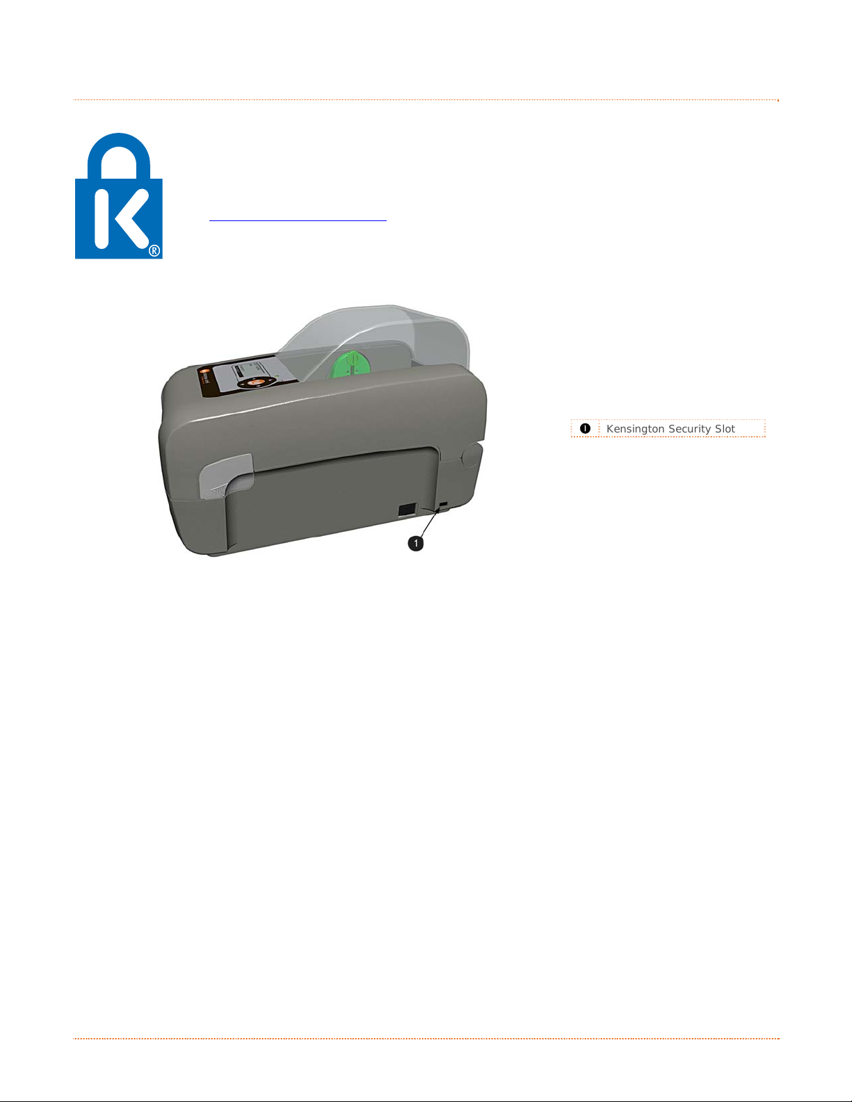
Professional + modules equipped with the Key Lock Option also include a built-in Kensington
Security Slot with a metal backing plate. The Kensington slot allows you to physically secure
the printer from being stolen by tethering it to a larger object like a desk or counter. There
are many security solutions offered by Kensington that are compatible with the slot.
Visit http://www.kensington.com
The Kensington Security Slot has been the industry standard since 1990, giving customers the
best option for physical security of computer and electronic equipment.
312
for a full line of locking options and accessories.
Kensington Security Slot
2 Chapter 1 – Getting Started
Page 9
p
u
t
e
S
r
e
t
n
i
r
P
r
P
P
2
2
2
2
.
1
2
.
1
2
.
This section explains how to connect your printer and load media (including ribbon, if equi pped for thermal
transfer operation).
2
.
2
2
.
2
2
.
2.2.1 Power Connections
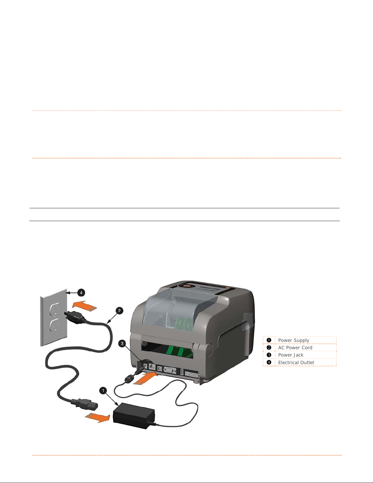
The printer is powered by an external auto-ranging power supply, which connects between the printer and an
electrical outlet. Ensure that the operating ranges of the power supply are compatible with your electrical
service, (see Appendix A for details) then connect power as follows:
I
n
t
r
o
d
u
c
t
c
c
u
u
c
i
c
t
i
c
t
i
t
i
n
t
i
n
t
i
n
I
n
t
r
o
o
t
n
n
n
d
r
o
d
n
e
n
e
n
e
1
I
n
C
o
C
o
2
C
Before connecting power to the printer, ensure that the Power Switch is in the OFF (O) position.
1) Connect the Power Supply to Power Jack of the printer.
r
o
o
o
g
g
g
n
n
n
t
t
i
t
i
h
h
h
n
n
e
e
e
e
t
e
t
P
r
i
n
P
t
r
i
n
t
r
i
n
t
P
e
e
e
r
r
r
r
r
S
S
e
e
t
t
u
u
p
p
2) Connect the AC Power Cord to the Power Supply.
3) Connect the AC Power Cord to an Electrical Outlet.
312
Power Supply
AC Power Cord
Power Jack
Electrical Outlet
Chapter 2 – Printer Setup 3
Page 10
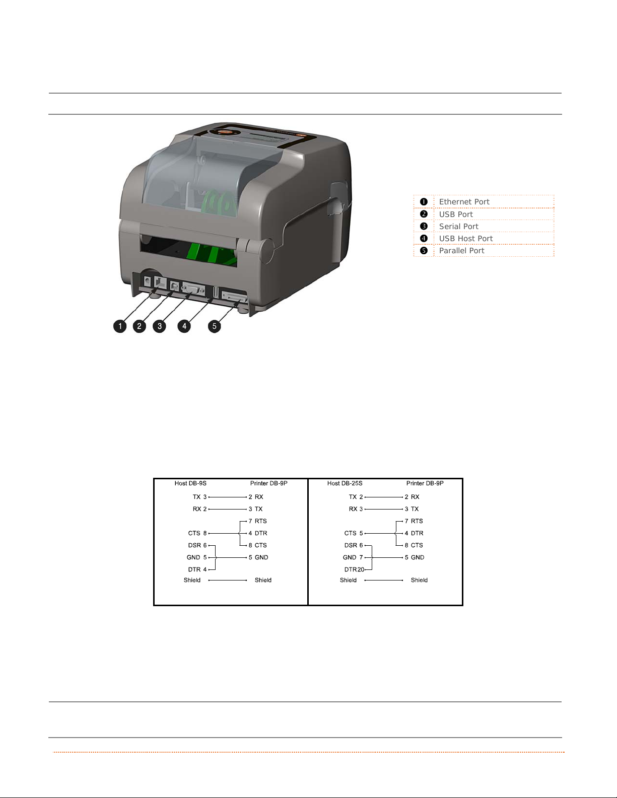
2.2.2 Interface Connections
Before connecting interface cables to the printer, ensure that the Power Switch is in the OFF (O) position.
312
Ethernet Port
USB Port
Serial Port
USB Host Port
Parallel Port
Cable Requirements
Choose the correct cable when interfacing the printer to the host:
The Parallel Port (optional) supports parallel communications via a 36-pin male mini-Centronics
connector. Bi-directional communications (forward and reverse channels) is supported when an IEEE
1284 compliant cable and supporting host software is used.
The Ethernet Port supports Wired LAN communications (see Appendix B for information).
The Serial Port supports RS-232C communications via a DB-9 connector with specif ic pin-outs
(interface cable part numbers and pin-outs are given below; contact your reseller to order). Serial port
settings are menu-selectable and must match the host settings.
Part # 32-2483-01
Part # 32-2301-01
The USB Port supports high-speed serial communications and requires a standard USB interface
cable.
The USB Host Port (optional). The USB Host Port allows the printer to accept external USB memory
devices for storing graphics, label formats, fonts, and firmware. The port can also accept an USB
keyboard for standalone, direct data (Line mode) input applications; see the Programmer’s Manual for
more information on how to utilize the port.
The printer automatically establishes communications with the first port through which valid data is
received. Afterward, a timeout period must be exceeded (or power must be cycled OFF and ON) to change
the established communications port.
4 Chapter 2 – Printer Setup
Page 11
2
.
3
L
o
a
d
i
n
g
M
e
d
i
a
2
.
2
.
3
L
o
a
d
i
n
g
M
3
L
o
a
d
i
n
The printer is equipped with an Adjustable Media Sensor and may require adjustment to match your
media choice, refer to Section 4.4.
g
e
M
e
d
d
i
a
i
a
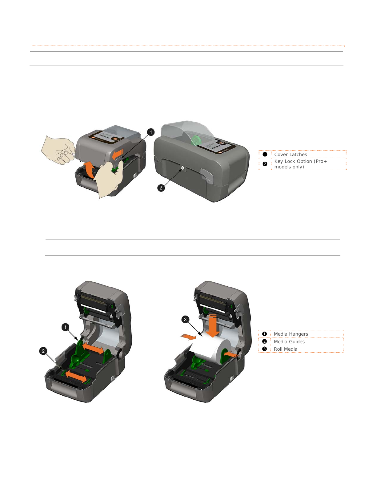
2.3.1 Loading Roll Media
Load media as follows:
1) Pull forward on the Cover Latches and lift up on the cover. Pro+ models have Key Lock option that
must be unlocked before the cover can be opened.
312
Cover Latches
Key Lock Option (Pro+
models only)
2) Slide the Media Guides outward.
Pro+ model Media Guides are equipped with Adjustable Media Core Hangers, see section 2.3.5.
3) Slide the Media Hangers outward and insert the Roll Media as shown. Allow the Media Hangers to
retract and grasp the media roll.
312
Media Hangers
Media Guides
Roll Media
Chapter 2 – Printer Setup 5
Page 12
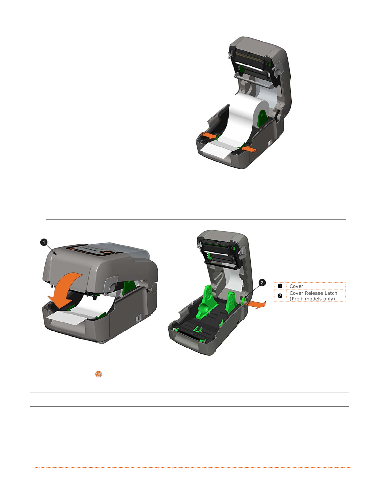
4) Pull out enough media to exit the front of
the printer. Adjust the Media Guides so
they are lightly touching the edge of the
media.
5) If using thermal transfer media (ribbon) proceed to Section 2.4 Loading Ribbon. Otherwise close
the printer’s Cover and press downward until latched. Pro
Pro+ models are equipped with a Cover Release Latch. Press outward on the latch to release cover.
312
Cover
Cover Release Latch
(Pro+ models only)
6) Press the
button to advance the media (if the Fault Light is lit, see Section 3.7.)
The printer is factory set to use gap media. If using another media type (for example, continuous
media), printer setup must be reconfigured; see Section 3.4
.
6 Chapter 2 – Printer Setup
Page 13
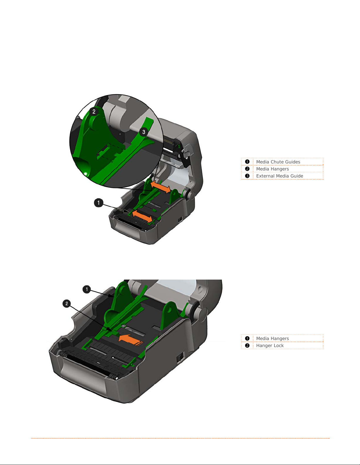
2.3.2 Loading - External Media
Using Internal Media Chute Guides Accessory (Professional model only)
Load media as follows:
1) Slide the Media Guides outward.
2) Slide the Media Hangers outward and install the two Media Chute Guides into the Media Hangers.
Media Chute Guides
Media Hangers
External Media Guide
3) Position the Media Hangers to match the width of the media being used. Slide the Hanger Lock
against the Media Hanger to hold this position.
Media Hangers
Hanger Lock
Chapter 2 – Printer Setup 7
Page 14
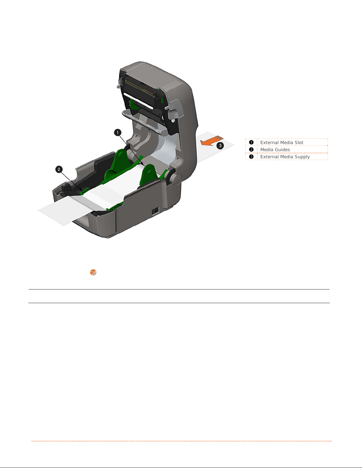
4) Route the media through the External Media Slot in the rear of the printer. Pull out enough media
to exit the front of the printer. Adjust the Media Guides so they are lightly touching the edge of
the media.
External Media Slot
Media Guides
External Media Supply
5) If using Thermal Transfer media (ribbon) proceed to Section 2.4 Loading Ribbon. Otherwise close
the printer’s Cover and press downward until latched.
6) Press the button to advance the media (if the Fault Light is lit, see Section 3.7.)
The printer is factory set to use gap media. If using another media type (for example, continuous
media), printer setup must be reconfigured; see Section 3.4
.
8 Chapter 2 – Printer Setup
Page 15
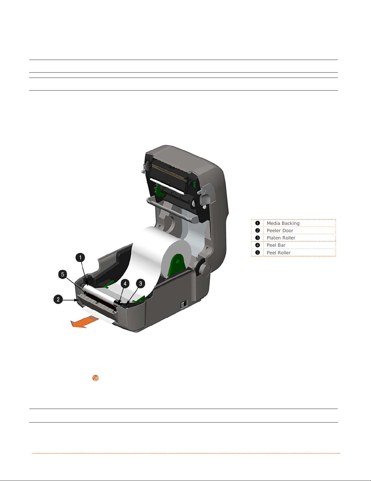
2.3.3 Loading Media with the Peel and Present Option
Load media for peeling (if the printer is equipped with the option) as follows:
When using the Peel Mechanism do not exceed a print speed of 4 IPS.
To utilize “Tear mode” with Peel and Present Option installed; move the Peeler Door to its open position.
1) Load media as described in Section 2.3, (steps 1-3).
2) Remove about 8 inches (200mm) of labels from the Media Backing.
3) Open the Peeler Door. Route the Media Backing over the Platen Roller and Peel Bar, and then
behind the Peel Roller and Peeler Door, as shown below.
312
Media Backing
Peeler Door
Platen Roller
Peel Bar
Peel Roller
4) Close the Peeler Door.
5) If using Thermal Transfer media (ribbon) proceed to Section 2.4 Loading Ribbon. Otherwise cl ose
the printer’s Cover and press downward until latched.
6) Press the
7) The printer will now peel each label and present it to the operator for removal. The indicator light
will flash orange and the next label will not feed/print until the previous label is removed.
The printer is factory set to use gap media. If using another media type (for example, continuous
media), printer setup must be reconfigured; see Section 3.4
button to advance the media (if the Fault Light is lit, see Section 3.7.)
.
Chapter 2 – Printer Setup 9
Page 16
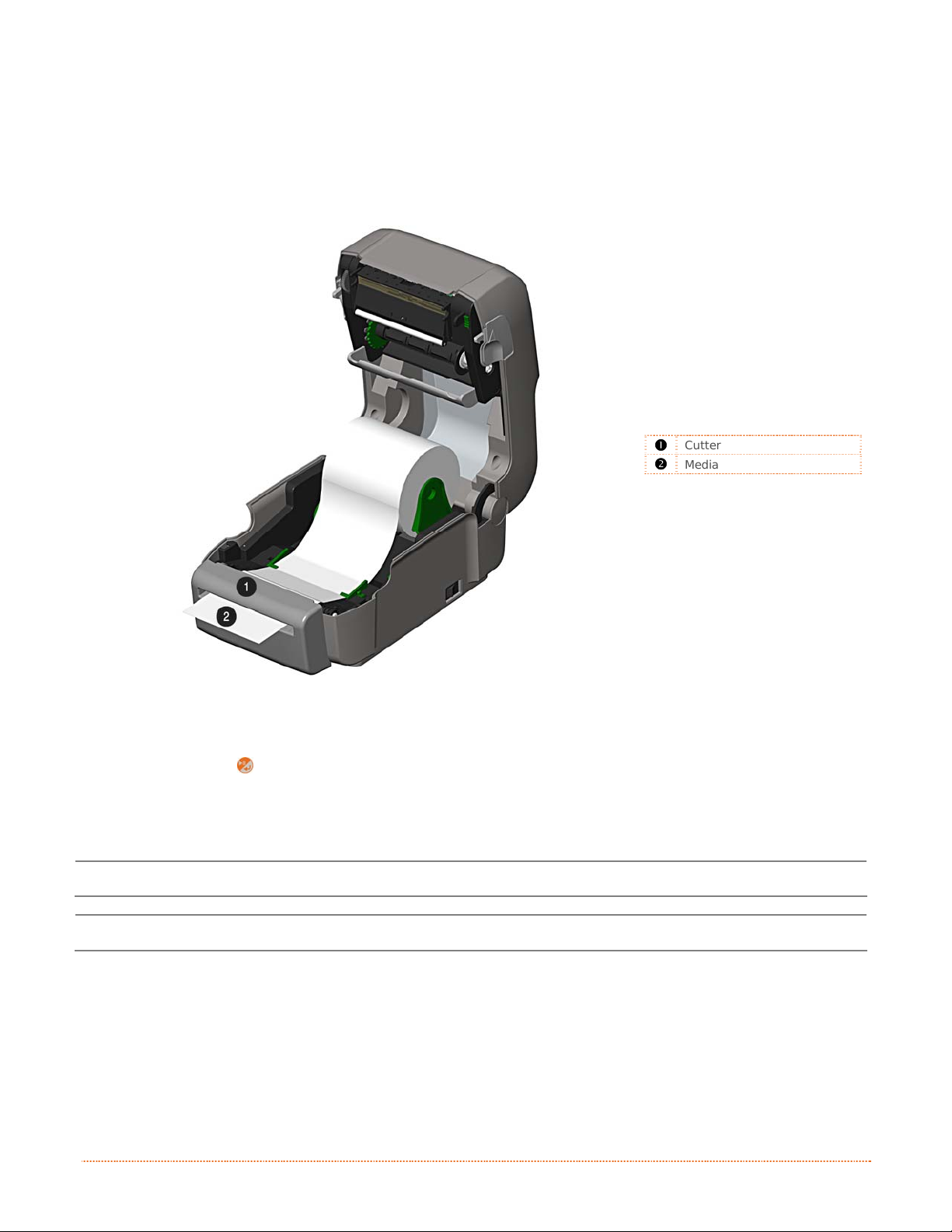
2.3.4 Loading Media with the Cutter Option
Load media for cutting (if the printer is equipped with the option) as follows:
1) Load media as described in Section 2.3, (steps 1-3).
2) Route the media through the opening in the Cutter.
312
Cutter
Media
3) If using Thermal Transfer media (ribbon) proceed to Section 2.4 Loading Ribbon. Otherwise close
the printer’s Cover and press downward until latched.
4) Press the button to advance the media (if the Fault Light is lit, see Section 3.7.). The printer
will now cut each label as it exits from the printer.
7) The printer will now peel each label and present it to the operator for removal.
If the printer is equipped with the Present Sensor Option, the indicator light will flash orange and the
next label will not feed/print until the previous label is removed.
The printer is factory set to use gap media. If using another media type (for example, continuous
media), printer setup must be reconfigured; see Section 3.4
.
10 Chapter 2 – Printer Setup
Page 17
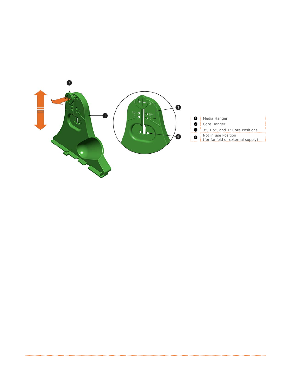
2.3.5 Adjustable Media Core Hangers (Pro+ models only)
The Adjustable Media Core Hangers allow for support of media rolls with 3”, 1.5”, or 1” cores.
To adjust:
1) Pull outward in on the Core Hanger and slide the Core Hanger up or down to the desired setting.
Be sure both core hangers are set to the same position.
312
Media Hanger
Core Hanger
3”, 1.5”, and 1” Core Positions
Not in use Position
(for fanfold or external supply)
Chapter 2 – Printer Setup 11
Page 18
2
.
4
L
o
a
d
i
n
g
R
i
b
b
o
n
2
.
4
L
o
a
d
i
n
g
R
i
b
2
.
4
L
o
a
d
i
n
g
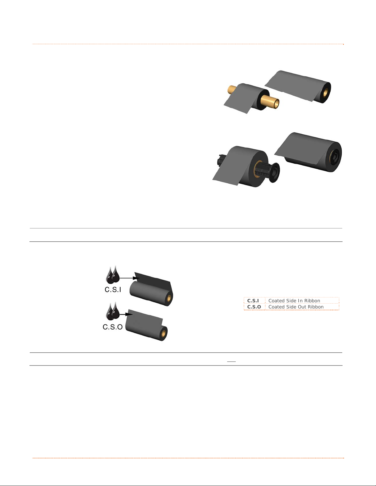
The printer is capable of using C.S.I (Coated Side In) and C.S.O (Coated Side Out) ri bbons in the following
configurations:
½” Core Ribbons
Ribbon Core Width: 4.3 inches (110mm)
Ribbon Width: 1.0 - 4.3 inches (25 - 110mm); Centered on core
1” Core Ribbons (with Ribbon Core Adapters, see section 2.4.1.)
Ribbon Core Width: 1.0 - 4.3 inches (25 - 110mm); Centered
on Ribbon Core Adapters
Ribbon Width: 1.0 - 4.3 inches (25 - 110mm); Centered on core
Load ribbon as follows:
If equipped with the thermal transfer option, the printer is factory set to use ribbon; see Section 3.4 to
change this setting if using direct thermal media.
1) Determine the type of ribbon (C.S.I or C.S.O) you are using.
b
R
i
b
b
o
o
n
n
312
C.S.I Coated Side In Ribbon
C.S.O Coated Side Out Ribbon
Ensure the inked side of the ribbon faces toward the label media, not the printhead.
12 Chapter 2 – Printer Setup
Page 19
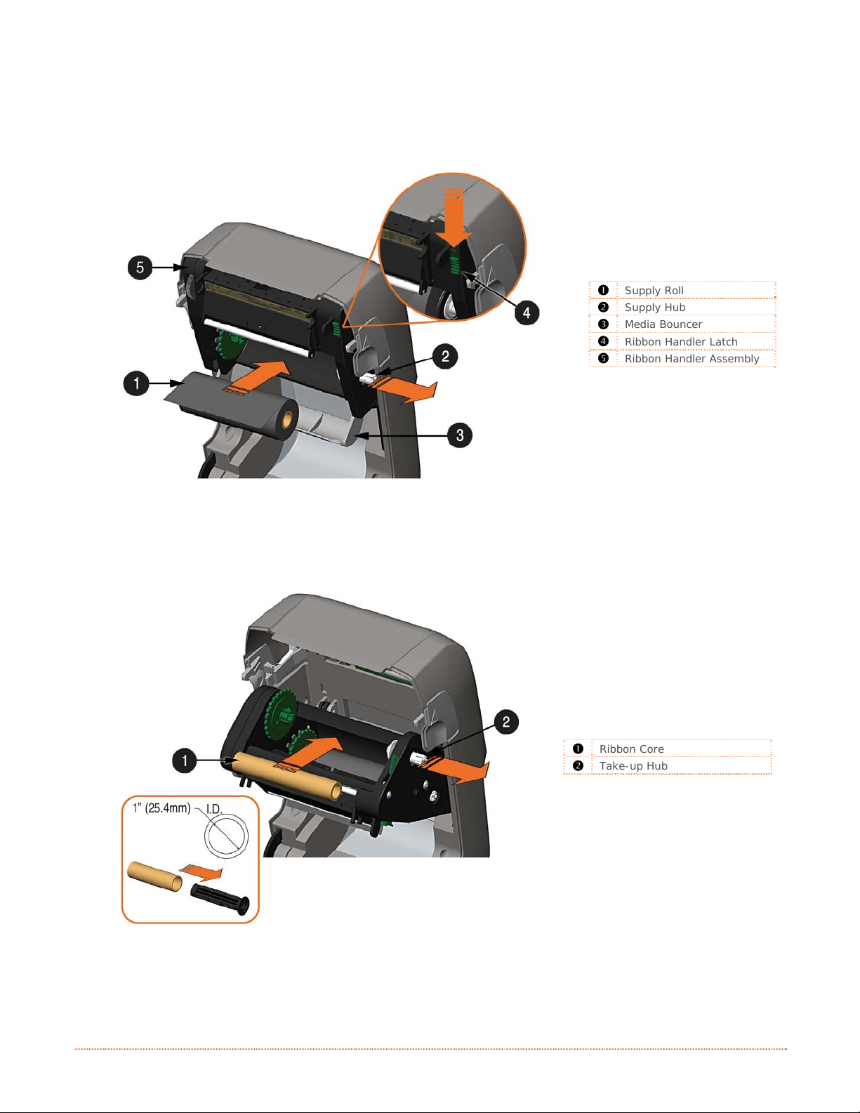
2) Push out the Supply Hub and load the Supply Roll into the printer as shown. Depending on the
size of the Supply Roll, the Media Bouncer may need to be pushed out of the way.
3) Once the Supply Roll is loaded, slide the Ribbon Handler Latch downward to unlatch the Ribbon
Handler Assembly.
312
Supply Roll
Supply Hub
Media Bouncer
Ribbon Handler Latch
Ribbon Handler Assembly
4) Push out the Take-up Hub and load an empty Ribbon Core into the printer as shown.
312
Ribbon Core
Take-up Hub
Chapter 2 – Printer Setup 13
Page 20
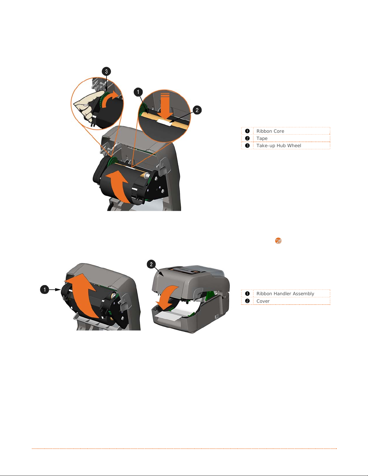
5) Route the ribbon from the supply roll to the Ribbon Core, as shown below.
6) If not already attached, affix the leader of the ribbon to the Ribbon Core using Tape. Rotate the
Take-up Hub Wheel several times to secure the ribbon.
312
Ribbon Core
Tape
Take-up Hub Wheel
7) Raise and latch the Ribbon Handler Assembly. Close the cover and press the
button to advance
the media (if the Fault Light is lit, see Section 3.7.)
312
Ribbon Handler Assembly
Cover
14 Chapter 2 – Printer Setup
Page 21
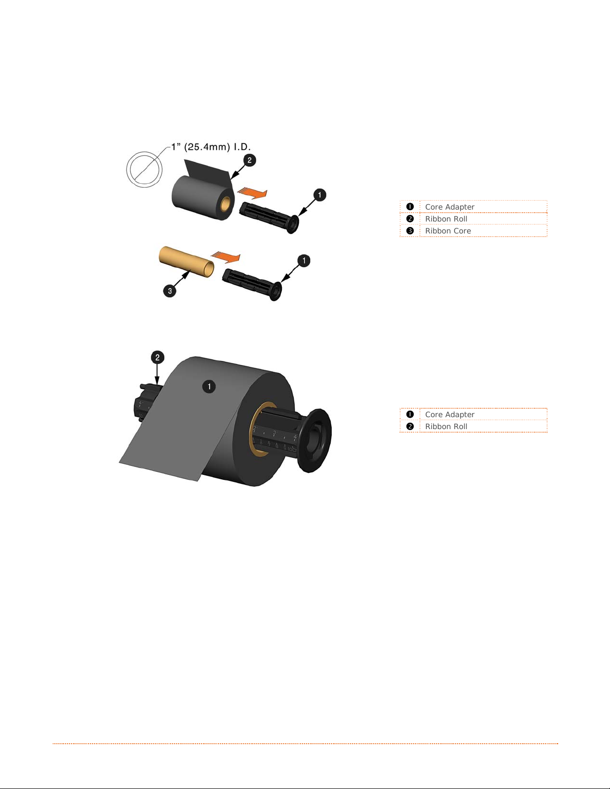
2.4.1 Using the Ribbon Core Adapters
When using ribbons with a 1” (25.4mm) I.D. core, a Core Adapter must be used.
1) Slide the Ribbon Roll (with the leader positioned as shown above) onto a Core Adapter. Slide an
empty Ribbon Core onto the remaining Core Adapter.
312
Core Adapter
Ribbon Roll
Ribbon Core
2) If using a narrow ribbon, position the Ribbon Roll so that it is centered on the Core Adapter. The
Core Adapters are marked in both inches and centimeters to aid in proper positioning.
Core Adapter
Ribbon Roll
312
Chapter 2 – Printer Setup 15
Page 22

16 Chapter 2 – Printer Setup
Page 23
n
o
i
t
a
r
e
O
O
p
p
p
e
e
r
r
a
a
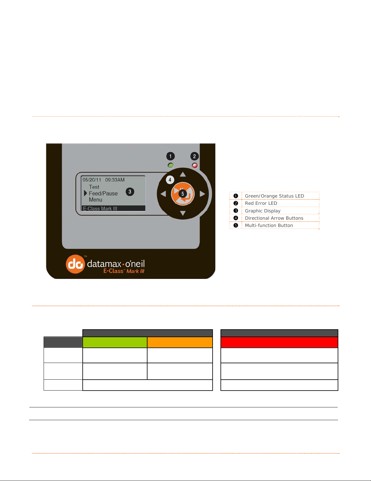
Green/Orange Status LED
Red Error LED
Graphic Display
Directional Arrow Buttons
Multi-function Button
t
i
o
o
i
t
n
n
P
r
P
P
3
3
3
3
.
1
3
.
1
3
.
The Front Panel consists of a graphic display, two indicator lights, four directional arrow buttons and one
multi-function button, as detailed in the following sections.
1
I
n
t
r
o
d
u
c
t
I
n
t
r
o
I
n
d
t
r
o
d
u
u
c
c
i
t
i
t
i
r
o
o
o
n
n
n
i
i
n
n
312
t
t
e
e
r
r
O
r
e
t
n
i
r
3
.
2
L
E
D
I
n
d
i
c
a
t
3
.
2
L
E
D
I
n
3
.
2
L
E
D
Two LED indicator lights provide a quick visual reference of printer operations and conditions, as defined
below:
Color Green Orange
Solid
Flashing
Off
Both indicators will be ON during power-up initialization and following a reset.
d
I
n
d
o
i
c
a
t
o
i
c
a
t
o
Ready to print
Processing/busy Paused/busy Out of stock\labels or printer jam..
r
s
r
s
r
s
LED 1 LED 2
Paused or Present
Sensor is blocked.
No power
TOF sensing error. Next TOF not Found.
Red
No Error
Chapter 3 – Printer Operation 17
Page 24
3
.
3
U
s
e
r
I
n
t
e
r
f
a
c
e
3
.
3
U
s
e
r
I
n
t
e
r
3
.
3
U
s
e
r
I
n
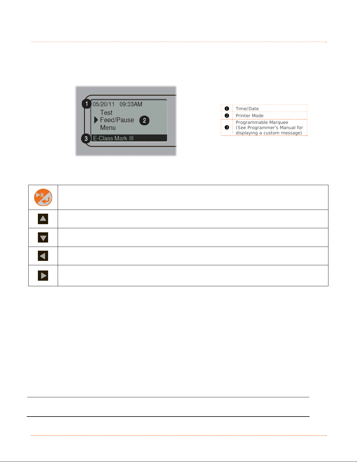
The User Interface is divided in three sections, Feed/Pause, Test, and Menu. Button functions are dependent
on the mode currently in use.
Use the Up and Down arrow buttons to scroll to the item and then press the center button to enter that menu
mode.
f
t
e
r
f
a
a
c
c
e
e
312
Time/Date
Printer Mode
Programmable Marquee
(See Programmer's Manual for
displaying a custom message)
3.3.1 Feed/Pause Mode
At idle: Feeds the media to the next label.
When printing: Pauses current print job; prompts user to resume or cancel
Scrolls upward to the next menu item
Scrolls downward to the next menu item
N/A
N/A
3.3.2 Test Mode
The Test Mode contains test and informational label selections:
Print Quality Label
Print Configuration
Ribbon Test Label
Test Label
Validation Label
Print Last Label
Network Report
Internally generated, these labels are printed at pre-selected media type, speed, and heat settings. Changes
to these print settings can be made via the Menu System or through host commands. When printing, use full
width media to capture the entire format; otherwise, adjust the printer and set the Label Width menu setting.
(1) Press the CANCEL KEY to stop printing.
(2) A printing delay can be set; see Print Test Rate in the Diagnostics menu branch.
18 Chapter 3 – Printer Operation
Page 25
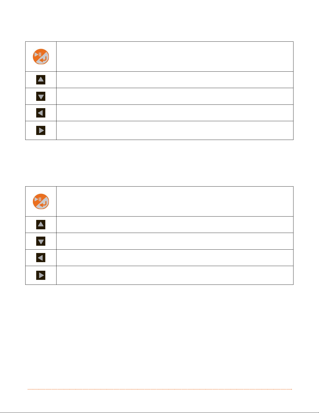
Enters the Test mode menu/sub-menu items. Prints the chosen test label.
Scrolls upward to the next menu item. Increments the Count value.
Scrolls downward to the next menu item. Decrements the Count value.
Exits the Test menu mode
Displays the ‘Count’ screen.
3.3.3 Menu Mode
The menu mode is covered in detail in Chapter 4.
Enters the Menu mode menu/sub-menu items. Enter/Accepts current prompt.
Scrolls upward to the next menu item. Increments the current value.
Scrolls downward to the next menu item. Decrements the current value.
Exits to the previous menus level
Enters the next menu/sub-menu item.
Chapter 3 – Printer Operation 19
Page 26

3
.
4
P
r
i
n
t
e
r
C
o
n
f
i
g
u
r
a
t
i
o
n
T
o
o
l
s
3
.
4
P
r
i
n
t
e
r
C
o
n
f
i
g
u
r
a
t
i
o
n
T
3
.
4
P
r
i
n
t
e
r
C
o
n
f
i
g
u
r
a
t
i
o
The printer contains many user adjustable parameters. These parameters are configurable using a few
methods. The table below lists the most popular ways of configuring the printer and the advantages of each.
Choose the method that best addresses your application.
Method Description Pros Cons For More Info
NETira CT (located on the
Accessories CD-ROM) is a
Windows based configuration
NETira CT
Program*
Internal Web
Pages*
utility that allows the user to
make changes to the existing
printer setup via a direct
connection to the host computer’s
serial, USB, Ethernet, or parallel
connection.
Internal web pages are simple
HTML pages that can be accessed
with any web browser via the
optional Ethernet port.
n
o
T
o
o
l
s
o
l
s
Easy to use, gives the
user the most control
of the printer.
Easy to use. Printer
can be configured from
any host connected to
the network regardless
of physical location or
host operating system.
No additional software
required.
Software must be
installed on a Windows
based host computer.
Printer must be
equipped with an
Ethernet or Wi-FI
option.
Depending on the
complexity of the
network, initial
connection may not be
possible until network
parameters are set via
another method.
See
Section 3.5
See
Appendix B
Windows
Driver
DPL
Programming
Commands
* Recommended methods
The Windows printer driver
(located on the Accessories CDROM).
DPL Programming Language
commands can be built into
custom label formats or sent
individually to the printer.
Many applications
require use of driver
for printing from 3
party applications. This
can be an all in one
solution for some users
that do not require
advanced setups.
DPL commands can be
built directly into label
formats which can
configure the printer
on the fly.
rd
Requires installation of
a driver on a Windows
based host.
Only basics parameters
can be configured.
DPL programming
knowledge needed.
See
Section 3.6
See the
Programmer’s
Manual
20 Chapter 3 – Printer Operation
Page 27
3
.
5
P
r
i
n
t
e
r
C
o
n
f
i
g
u
r
a
t
i
o
n
U
t
3
.
5
P
r
i
n
t
e
r
C
o
n
f
i
g
u
r
a
t
i
o
3
.
5
P
r
i
n
t
e
r
C
o
n
f
i
g
u
r
NETira CT (located on the Accessories CD-ROM) is a Windows-based configuration utility that allows the user
to make changes to the existing printer setup via a direct connection to the host computer’s serial, USB,
Ethernet, or parallel ports.
NETira Features:
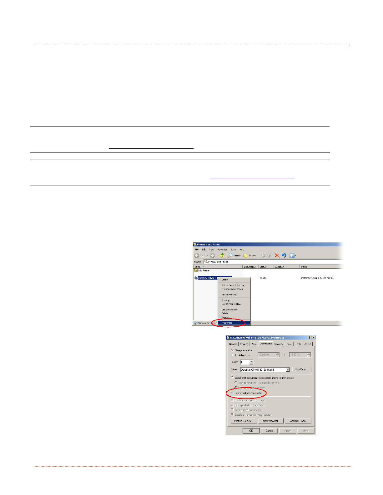
USB and Parallel Port Connection Requirements
Using Netira CT with an USB or parallel port connection requires a Windows driver to be installed and the
driver to be set to “Print directly to the printer”. Install the Windows driver as described in section 3.6. Then
follow the steps below to set the driver setting:
1) Open the list of installed printers on your PC.
2) Right click on the printer and select Properties
3) In the Driver Properties window, click on the
4) Click the “Print directly to the printer” radio
USB and parallel port connections will now be
available for use with Netira CT.
Allows Real-Time Control/Query of Printer Configuration
Define and Save Optimal Configurations for Applications
Saved Configurations can be Shared with other Printers and Sent via Email
Download Files, Formats and Fonts
Query Memory Modules
Be sure to use the NETira utility located on the Accessories CD-ROM that is included with your
printer. Older versions might not operate correctly with some printers. For the latest version please
visit our web site at http://www.datamax-oneil.com
Be sure your printer’s firmware version is 9.03_0016B or greater. Firmware is available from our
website, for the latest version please visit our web site at http://www.datamax-oneil.com
Windows XP
Open Printer and Faxes by clicking the Start
button, and then Settings, and then click on Printer
and Faxes.
Windows 7
Open Devices and Printers by clicking the Start
button, and then click on Devices and Printers.
from the drop down menu.
Advanced tab.
button. Then click OK.
a
n
t
i
o
n
i
U
t
i
U
t
i
(
N
E
T
i
r
a
C
T
)
l
i
t
y
(
N
E
T
i
r
a
l
i
t
y
(
N
l
i
t
y
E
T
i
r
a
C
C
T
T
)
)
Chapter 3 – Printer Operation 21
Page 28

NETira CT Usage
1) Once installed launch the NETira CT configuration utility:
2) Be sure the printer is ‘ON’. Connect the host to the printer (see Section 2.2.2 Interface Connections).
For Serial Connections:
a) Query the printer by using the ‘Auto Detect’ button.
This will connect to the printer and retrieve the
setting currently stored in the printer.
For USB and Parallel Connections:
Close the ‘Open a configuration file…’ dialogue box.
a) In the toolbar, from the drop down menu box,
select the appropriate port Then click on the Query
Printer Icon
For Ethernet Connections:
Close the ‘Open a configuration file…’ dialogue box.
a) In the toolbar, Click on the ‘ TCP/IP Configuration’
Icon
.
b) In the ‘TCP/IP Configuration’ dialogue box enter the
IP address of the printer, Port: 9100 and click ‘OK’.
(The IP address is displayed on the printer’s
Network Report and Configuration Labels).
c) In the toolbar, from the drop down menu box, select
“TCP_IP”. Then click on the Query Printer Icon
.
.
22 Chapter 3 – Printer Operation
Page 29

3) At this point you may browse the Printer Component
categories and make any changes necessary to the
printer configuration.
4) Once complete, send the new settings to the printer using
the ‘Send’ button.
Note: When sending the changes to the printer, only the
changes displayed on the current page will be
sent. You must click the ‘Send’ button for each
page that has been modified.
Chapter 3 – Printer Operation 23
Page 30

3
.
6
W
i
n
d
o
w
s
D
r
i
v
e
r
3
.
6
W
i
n
d
o
w
s
D
r
3
.
6
W
i
n
d
o
w
s
The Windows driver is located on the Accessories CD-ROM included with your printer. For the latest version
please visit our web site at http://www.datamax-oneil.com
i
D
r
v
e
r
i
v
e
r
Installing the Windows Driver:
1) Place the Accessories CD-ROM included with your
2) Once the CD-ROM starts select your printer model then
3) When prompted, select your pri nter from the list, (i.e.
Be sure your printer’s firmware version is 9.03_0016B or greater. Firmware is available from our
website, for the latest version please visit our web site at http://www.datamax-oneil.com
Be sure your printer’s USB Mode is set to “Printer”. This mode can be viewed/changed via the
printer’s front panel menu under: Communications> USB Port> USB Device Class.
printer into your computers CD-ROM drive.
“Install Driver” from the menu and follow the
instructions on the screen to install.
Datamax-O’Neil E-4xxx Mark III). Continue to follow
the on-screen instructions to install the driver.
24 Chapter 3 – Printer Operation
Page 31

Important Notes:
The Windows driver functions the same as any other Windows printer. While built-in help files provide
information on all settings, there are some important setting parameters that should be observed for trouble
free printing:
Page Setup Tab: Stock
It is important that the Stock setting matches the
size of the label you are using. If you cannot find a
match for your label click New and enter the
dimensions of your label.
Options Tab: Print Speed & Printhead Temperature
These two settings will have the greatest effect on
print quality. Some label stocks will require more
heat and slower print speeds to generate a quality
image.
The Windows application software used to create the label format will likely have a "Page Setup" screen. This
will also need to match the size of the label you are using.
Chapter 3 – Printer Operation 25
Page 32
3
.
7
M
e
d
i
a
C
a
l
i
b
r
a
t
i
o
n
3
3
.
7
M
e
d
i
a
C
a
l
i
b
r
.
7
M
e
d
i
a
C
a
a
l
i
b
r
a
t
i
o
n
t
i
o
n
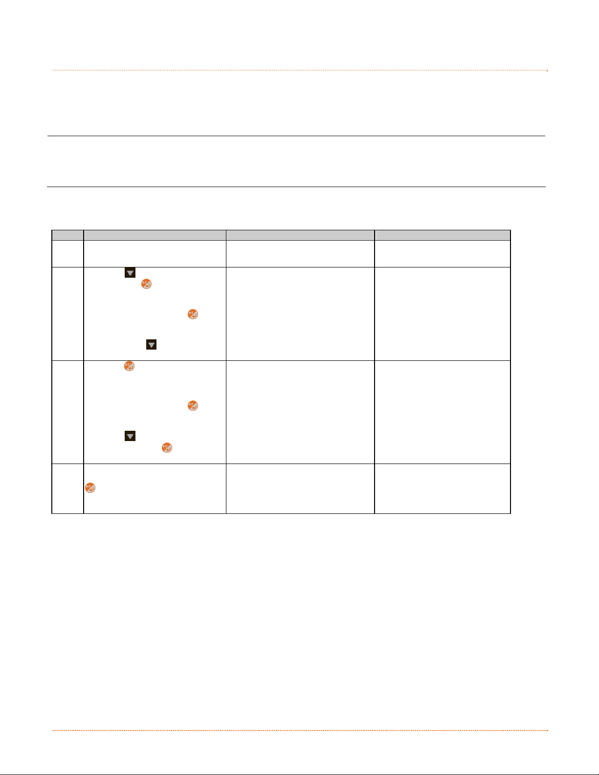
3.7.1 Quick Calibration
Ensure the printer is properly loaded with media, proceed with calibration as follows:
This calibration is not necessary when using continuous stock.
Calibrate the printer as follows:
Step Action Displayed Message Comment
Calibration Hints:
Media containing large gaps may require a change in the Paper Out Distance before proceeding.
A Turn ON the printer.
Using the
and press the
Make sure MEDIA SETTINGS is
B
highlighted and press the
button.
Then using the
SENSOR CALIBRATION.
Press the
SENSOR CALIBRATION.
Make sure QUICK CALIBRATION is
highlighted and press the
C
button.
Using the
and then press the
proceed.
With the media installed and the
cover closed, press and hold the
D
button until at least 2 full labels
have been fed from the printer and
then release.
There are two possible outcomes:
CALIBRATION COMPLETE - will be displayed, and the media will be advanced to the next top of form
if calibration was successful; or,
CALIBRATION FAILED will be displayed if calibration was not successful. In this case, check the hints
listed below to help resolve the problem:
WARNING LOW BACKING is a normal message when calibrating die-cut media mounted on a highly
translucent liner or notched tag stocks.
If the initial attempt fails, perform the Manual Calibration routine, see Section 3.7.2.
button scroll to MENU
button.
button, scroll to
button to access
button, scroll to YES
button to
(Printer Menu)
Quick Calibration
No
>Yes
Press/Hold Enter Key
Wait briefly for initialization to
complete.
Select NO to abort this
procedure.
26 Chapter 3 – Printer Operation
Page 33
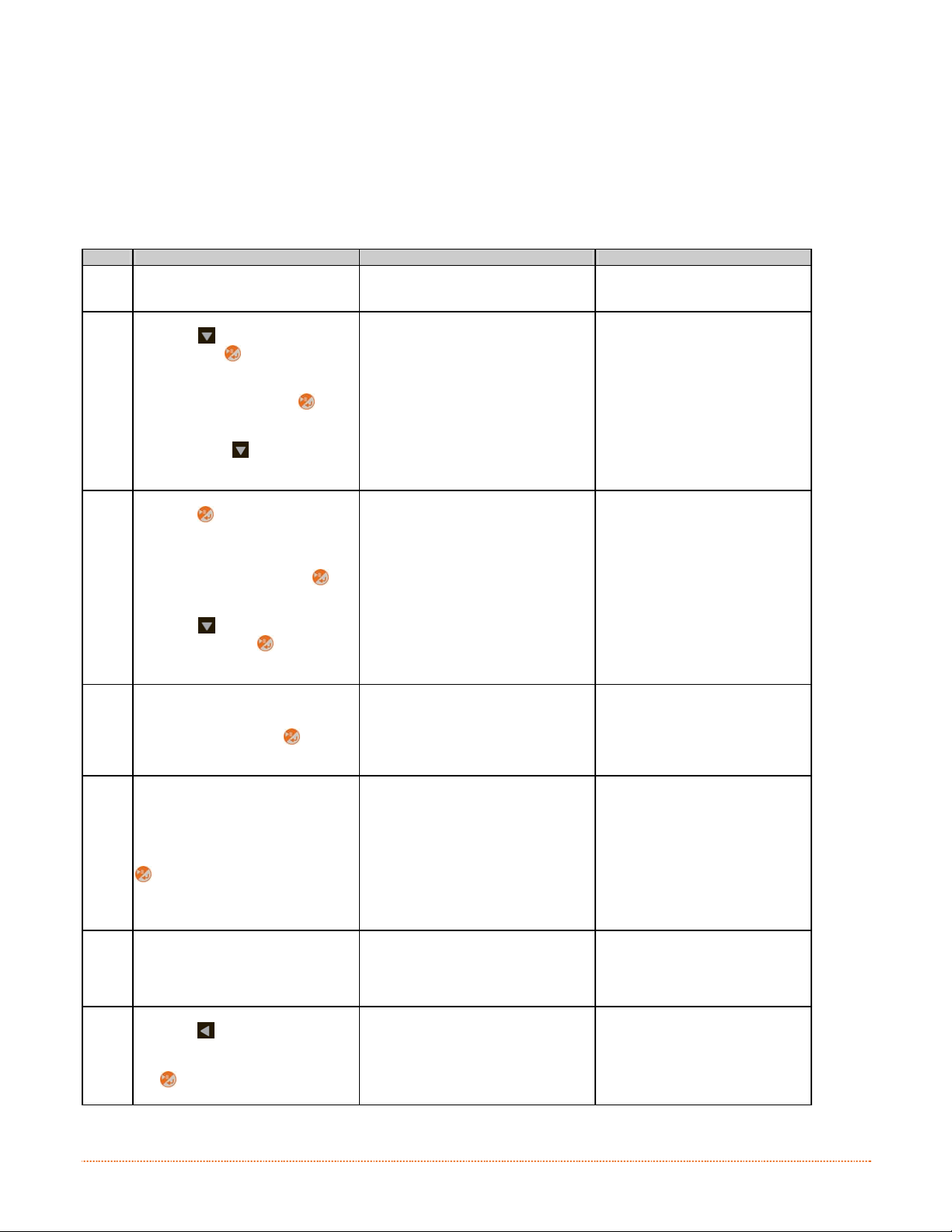
3.7.2 Manual Calibration
The Manual Calibration can be performed using the NETira CT Utility (see Section 3.5) or using the front panel
buttons via the printer’s menu, see Section 4.4.
Manual Calibration provides dynamic readings, which can be helpful when using media with small positioncritical notches or marks.
Calibrate the Media Sensor using the steps below:
Step Action Displayed Message Comment
A
Turn ON the printer.
Using the
and press the
button scroll to MENU
button.
Make sure MEDIA SETTINGS is
B
highlighted and press the
(Printer Menu)
button.
Then using the
button, scroll to
SENSOR CALIBRATION.
Press the
button to access
SENSOR CALIBRATION.
C
Make sure MANUAL CALIBRATION
is highlighted and press the
button.
Using the
and then press the
button, scroll to YES
button to
Manual Calibration
No
>Yes
proceed.
D
With no media installed and the
cover closed, press the
button.
Remove Label Stock
Press Enter
Yyy
Load the media. Be sure the Media
Sensor is positioned correctly.
E
With the media installed and the
cover closed, press and hold the
button until at least 2 full labels
Please Reload Media
Press/Hold Enter Key
yyy
have been fed from the printer and
then release.
F Observe the calibration result. Calibration Complete
G
Press the
the menu, select YES at the SAVE
CHANGES prompt and then press
the
repeatedly to exit
The printer is now ready for use.
button.
Wait briefly for initialization to
complete.
Select NO to abort this
procedure.
This sets the empty value, where
“yyy” represents the current
sensor reading.
Unless otherwise noted, do not
move the Media Sensor after this
step.
Calibration was successful.
If WARNING LOW BACKING is
displayed, calibration was still
successful.
Chapter 3 – Printer Operation 27
Page 34
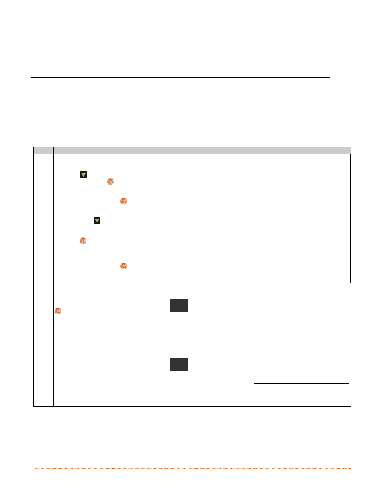
3.7.3 Advanced Entry Calibration
Advanced Entry is an alternate calibration method for special-case media types, where sensor readings are
taken using different sampling algorithms and from a list of these readings the best algorithm is selected for
manual entry into the database.
Advanced Entry Calibration should be used only when Manual Calibration proves unsuccessful.
Calibrate the Media Sensor using the steps below:
Step Action Displayed Message Comment
A Turn ON the printer.
B
C
D
The Sensor Calibration menu item is only accessible in the Advanced Menu mode.
Wait briefly for initialization to
complete.
Using the
MENU and press the
Make sure MEDIA SETTINGS is
highlighted and press the
button.
Then using the
SENSOR CALIBRATION.
Press the
SENSOR CALIBRATION.
Make sure ADVANCED ENTRY is
highlighted and press the
button.
Scroll to TRAN SENSOR GAIN (or
REFL SENSOR GAIN, if using
reflective media) then press the
button.
button scroll to
button.
button, scroll to
button to access
(Printer Menu)
ADVANCED ENTRY
TRAN SENSOR GAIN
202
17
(0 - 31)
The following examples detail die-cut
media calibration; however, unless
otherwise noted, the reflective media
procedure is the same.
Do not position the Media
Sensor under a perforation;
and if using preprinted media,
ensure the label area placed
over the sensor is free of text,
graphics, lines, etc.
Install media. Position the Media
E
in the Media Sensor and close the
cover.
TRAN SENSOR GAIN
202
17
(0 - 31)
28 Chapter 3 – Printer Operation
Page 35

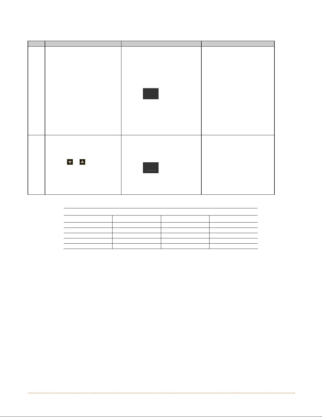
Advanced Entry Calibration (continued)
Step Action Displayed Message Comment
Using the
Gain Number to 0.
Record the sensor reading as a
F
Label Value for Gain Number 00 in
a table (32 rows by four columns,
with headings similar to those
shown below.)
or button, set the
TRAN SENSOR GAIN
253
0
(0 - 31)
This is the Label Value for a gain
setting of 0.
Sample Calibration Table
Gain Number Label Value TOF Value Difference Value
00 253
01
02
…
31
Step Action Displayed Message Comment
Using the
Gain Number by one and then
Record the Label Value.
G
Repeat this process for each Gain
Number.
button, increment the
TRAN SENSOR GAIN
250
1
(0 - 31)
This is the Label Value for a gain
setting of 1.
Sample Calibration Table
Gain Number Label Value TOF Value Difference Value
00 252
01 250
02 248
… …
31 09
Chapter 3 – Printer Operation 29
Page 36
Advanced Entry Calibration (continued)
Step Action Displayed Message Comment
Raise the cover assembly then
proceed according to the media
type:
Die-cut – Remove a label or two
from the liner then position the
liner in the Media Sensor.
H
Notched – Position the Media in
the Media Sensor under the notch.
Reflective – Position the Media in
the Media Sensor under the black
mark.
Lower and latch the Cover
Assembly.
Using the
I
Gain Number to 0.
Record the reading as a TOF Value
for Gain Number 0 in the table.
or button, set the
TRAN SENSOR GAIN
09
TRAN SENSOR GAIN
248
31
(0 - 31)
0
(0 - 31)
(1) Do not position the Media
Sensor under a perforation; and
if using preprinted media, ensure
the label area placed over the
sensor is free of text, graphics,
lines, etc.
(2) Do not move the Media
Sensor after this step.
This is the TOF Value for a gain
setting of 0, where “248”
represents the current sensor
reading.
Sample Calibration Table
Gain Number Label Value TOF Value Difference Value
00 252 248
01 250
02 248
… …
31 09
30 Chapter 3 – Printer Operation
Page 37
Advanced Entry Calibration (continued)
Step Action Displayed Message Comment
Using the
Gain Number by one. Record the
J
TOF Value. Repeat this process for
each Gain Number.
button, increment the
TRAN SENSOR GAIN
245
1
(0 - 31)
These are TOF Values, where
“245” represents the current
sensor reading.
Sample Calibration Table
Gain Number Label Value TOF Value Difference Value
00 252 248
01 250 245
02 248 234
… … …
31 09 14
Step Action Displayed Message Comment
In your sample calibration table,
where both the Label Value and
TOF Value are at least 20, subtract
the amounts and record the result
as a Difference Value (see below).
K
Identify the largest Difference
Value and the corresponding Gain
Number. This Gain Number will be
used to resample the media.
TRAN SENSOR GAIN
14
31
(0 - 31)
In the example below, Gain
Number 18 is chosen because;
both values are at least twenty
and it has the highest Difference
Value.
Sample Calibration Table
Gain Number Label Value TOF Value Difference Value
00 252 248 4
01 250 245 5
02 248 234 14
… … … …
15 188 63 125
16 184 51 133
17 179 38 141
18 174 25 149
19 170 19 N/A
… … … …
31 132 14 N/A
Chapter 3 – Printer Operation 31
Page 38

Advanced Entry Calibration (continued)
Step Action Displayed Message Comment
Using the
Gain Number determined in the
L
previous step. Press the
to enable the setting.
Press the
enter the TRAN SENSOR GAIN (or
REFL SENSOR GAIN, if using
reflective media) menu item.
Complete a table (see example
below) using new measurements,
as follows:
(A) Raise the Cover Assembly.
Place the label over the Media
Sensor then lower and latch the
Cover Assembly. Record the
sensor reading as “Paper”.
M
(B) Raise the Cover Assembly.
Place the liner, notch, or mark
over the Media Sensor then lower
and latch the Cover Assembly.
Record the sensor reading as “Gap
(or Mark)”.
(C) Raise the Cover Assembly.
Remove all media from the Media
Sensor then lower and latch the
Cover Assembly. Record the
sensor reading as “Empty”.
or button, set the
button
button again to re-
OK
TRAN SENSOR GAIN
yyy
18
(0 - 31)
This example uses Gain Number
18.
Where “yyy” is a numerical value
representing the current sensor
reading.
The re-sampled values may
differ from those previously
noted. This is normal; do not
readjust the Media Sensor.
Selected Gain Table
Gain Number Paper Gap (or Mark) Empty
18 174 42 9
32 Chapter 3 – Printer Operation
Page 39
Advanced Entry Calibration (continued)
Step Action Displayed Message Comment
Press the
button to exit the
current menu level.
Using the
PAPER SENSOR LEVEL (or if using
reflective media, REFL PAPER
N
LEVEL) and then press the
button.
Using the
Paper value determined in Step M
and then press the
Using the
SENSOR LEVEL (or, if using
reflective media, MARK SENSOR
LEVEL) and then press the
button.
O
Using the
Gap (or Mark) value determined in
Step M and then press the
button.
button, scroll to
or button, set the
button.
button, scroll to GAP
or button, Set the
PAPER SENSOR LEVEL
GAP SENSOR LEVEL
174
(0 - 255)
042
(0 - 255)
This is the Paper value.
This is the Gap (or Mark) value.
Using the
EMPTY SENSOR LEVEL and then
press the
P
Set the Empty value determined in
Step M and then press the
button.
Press the
the menu, select YES at the SAVE
Q
CHANGES prompt and then press
the
button, scroll to
button.
repeatedly to exit
button.
EMPTY SENSOR LEVEL
Save Changes?
No
>Yes
9
(0 - 255)
This is the Empty value.
Save Changes. The printer is
ready for use.
If the calibration attempt fails, try desensitizing the sensor as follows:
Go to MEDIA SETTINGS / SENSOR CALIBRATION / ADVANCED ENTRY / TRAN (or REFL) SENSOR GAIN
and lower the corresponding GAIN SETTING by one.
Exit the menu and save your changes. Test your media at the new setting. If necessary, repeat until a
usable Gain Setting is obtained.
Chapter 3 – Printer Operation 33
Page 40

34 Chapter 3 – Printer Operation
Page 41

m
e
t
s
y
S
u
n
e
e
e
y
y
y
e
n
e
n
e
s
t
e
m
O
m
n
n
n
u
u
u
O
O
v
v
v
s
t
e
m
s
t
e
r
M
e
r
M
e
r
M
e
u
u
e
r
v
e
r
v
e
r
v
i
i
i
e
e
e
S
S
w
w
w
y
y
s
s
t
t
e
e
m
m
M
M
M
4
4
4
4
.
1
4
.
1
4
.
1
The Menu System contains two modes, each with a differing level of access to secondary menus or functions:
4
.
2
4
.
2
4
.
2
The User Menu contains basic selections in these menus:
M
e
n
u
e
e
e
n
n
S
u
S
u
S
U
s
U
s
U
s
M
e
M
e
The User Menu accesses basic printer settings and functions
The Advanced Menu accesses all operational settings, functions, and diagnostics
Prompts may appear before menu access is granted and before changes are enacted; see Security
for details.
T
h
T
h
T
h
Media Settings
Print Control
Printer Options
System Settings
(1) Some setting changes will only become effective (and saved) after selecting YES at the Save
Changes prompt.
(2) Labeling software may, in some cases, override the printer menu settings; see Advanced Menu
for details.
Chapter 4 – Menu System 35
Page 42

4
.
3
T
h
e
A
d
v
a
n
c
e
d
M
e
n
u
4
.
3
T
h
e
A
d
v
a
n
c
e
d
M
4
.
3
T
h
e
A
d
v
a
n
c
e
The Advanced Menu contains all setting, control, and functional selections in these menus:
Media Settings
Print Control
Printer Options
System Settings
Communications
Diagnostics
After selecting the Advanced Menu, it will be shown whenever the MENU branch is accessed. To enable the
Advanced Menu, proceed as follows:
button to scroll to MENU and then press the button.
button, scroll to SYSTEM SETTINGS then press the button.
button, scroll to ADVANCED MENU then press the button. (Upon completion, OK
1. Press the
2. Using the
3. Be sure the cursor is next to MENU MODE then press the
4. Using the
will be displayed and the printer will exit the menu system.)
(1) Some setting changes will only become effective (and saved) after selecting YES at the Save
Changes prompt.
(2) Labeling software may, in some cases, override the printer menu settings; see Advanced Menu /
Communications / Host Settings to avoid potential conflicts.
(3) To return to the User Menu, re-select it or restore the factory defaults.
d
e
M
e
n
n
u
u
button.
36 Chapter 4 – Menu System
Page 43

4
.
4
M
e
n
u
D
e
t
a
i
l
s
4
4
.
4
M
e
n
u
D
e
.
4
M
e
n
u
t
D
e
t
a
a
i
l
s
i
l
s
Media Settings
The Media Settings menu contains label and ribbon sensing and sizing functions, as well as printhead cleaning
selections:
Media Type
Media Index Type
Auto Calibration*
Label Length
Maximum Label Length*
Paper Empty Distance*
Label Width
Ribbon Low Options*
Sensor Calibration*
Printhead Cleaning*
Items denoted with an asterisk (*) are only accessible through the Advanced Menu.
The menu selections are defined as follows:
DISPLAYED ITEM ITEM DESCRIPTION
MEDIA TYPE Selects the method used to print labels and should be set according to the type of media being
DIRECT THERMAL Sets use for media that is heat reactive to produce an image.
THERMAL TRANSFER Sets use for media that requires a ribbon to produce an image.
MEDIA INDEX TYPE Selects the top-of-form (TOF) sensing method used to determine the leading edge of the label,
GAP TOF will be recognized by sensing the gaps in the media. (Default Setting)
NOTCH TOF will be recognized by sensing the notches on the edge of the media.
HOLE TOF will be recognized by sensing the holes in the field of the me dia.
BLACK MARK TOF will be recognized by sensing the reflective (black) marks on the underside of the media.
CONTINUOUS No TOF sensing will be used; instead, LABEL LENGTH (in Media Settings) is used.
AUTO CALIBRATION The printer will sense each label as it exits the printer an d continually make sensor adjustments
ENABLE (Default Setting)
DISABLE Printer will use the stored calibration values
LABEL LENGTH Determines the length of the label (0 - 99.99 inches) when the SENSOR TYPE is set to
4.00 Is the default setting.
MAXIMUM LABEL LENGTH Sets the distance (0 - 99.99 inches) that the printer will feed media to find TOF (when the Sensor
8.00 Is the default setting.
PAPER EMPTY DISTANCE Sets the distance (0 - 99.99 inches) the printer will attempt to feed before an Out Of Stock Fault
0.25 Is the default setting.
LABEL WIDTH Sets the maximum printable width. Objects extending beyond this setting will NOT print, wher e:
4.00 Is the default setting.
Maximum Label Length should typically be 2.5 to 3 times the physical length of the label.
When using clear or translucent media, this setting should be longer than the actual label size.
used, where:
where:
to ensure the best possible calibration.
CONTINUOUS, where:
Type is set to GAP or REFLECTIVE) before a TOF Fault is declared, where:
is declared, where:
Chapter 4 – Menu System 37
Page 44

DISPLAYED ITEM ITEM DESCRIPTION
RIBBON LOW OPTIONS Defines the printer response when THERMAL TRANSFER mode is selected and the ribbon supply
RIBBON LOW
DIAMETER
0.50 Is the default setting.
PAUSE ON RIBBON
LOW
ENABLE Pauses when a Ribbon Low Diameter condition is detected; the PAUSE Key must be pressed to
DISABLE No action is required by the operator; printing can continue until a Ribbon Fault is declared.
SENSOR CALIBRATION Selects the media sensor calibration method, where:
QUICK CALIBRATION Sets the values via internal printer calculations by feeding blank labels through the printer.
MANUAL CALIBRATION Manual calibration that scans media and backing and out of stock condition to calculate the proper
ADVANCED ENTRY Sets the values via manual entry (typically for hard to calibrate label stocks), as described in t he
PAPER SENSOR
LEVEL
REFL PAPER LEVEL Establishes the threshold for the reflective value (0 - 255), where 170 is the default setting.
GAP SENSOR LEVEL Establishes the threshold for the gap value (0 - 255), where 040 is the default setting.
MARK SENSOR
LEVEL
EMPTY SENSOR
LEVEL
TRAN SENSOR
GAIN
REFL SENSOR GAIN Establishes the sensitivity of the reflective sensor (0 - 31), where 15 is the default setting.
PRINTHEAD CLEANING Controls the automatic cleaning alert and function, where:
CLEAN HEAD SCHEDULE Specifies the inch (or centimeter) count at which to clean the printhead, and if exceeded three
CLEAN HEAD COUNTER Indicates the number of inches (or centimeters) since a cleaning was last initiated.
RESET COUNTER Resets the Clean Head Counter to zero to restart the Clean Head Schedule.
CLEAN HEAD NOW Initiates the cleaning process and resets the Clean Head Counter.
begins to diminish.
Sets the ribbon supply threshold diameter (1.00 - 2.00 inches) that will trigger a Low Ribbon
Warning prompt, where:
Allows the printer to enter a paused condition when Ribbon Low Diameter is met, where:
proceed with the print job.
(Default Setting)
calibration.
ADVANCED ENTRY CALIBRATION where:
Establishes the threshold for the paper value (0 - 255), where 170 is the default setting.
Establishes the threshold for the mark value (0 - 255), where 040 is the default setting.
Establishes the threshold for the empty value (0 - 255), where 000 is the default setting.
Establishes the sensitivity of the transmissive sensor (0 - 31), where 15 is the default setting.
times, declare a Head Cleaning Fault. (Note that the specified count [0 - 200 inches] will be
multiplied by one thousand, and that zero [the default setting] will disable the function.)
38 Chapter 4 – Menu System
Page 45

Print Control
The Print Control menu contains printing throughput, offset and custom setup functions:
Items denoted with an asterisk (*) are only accessible through the Advanced Menu.
The menu selections are defined as follows:
DISPLAYED ITEM ITEM DESCRIPTION
HEAT Controls the burn time (0 - 30) of the printhead (and is equivalent to the Heat setting in many
10 Is the default setting.
PRINT SPEED Controls the rate of label movement during printing, where:
x.x in/sec Default setting is dependant on printer model.
FEED SPEED Controls the rate of label movement between printing areas, where:
x.x in/sec Default setting is dependant on printer model.
REVERSE SPEED Controls the rate of label movement (2.0 - 5.0 inches per second) during backup positioning, where:
2.0 in/sec Is the default setting.
SLEW SPEED Controls the rate of label movement (2.0 - 16.0 inches per second) between printing areas when
x.x in/sec Default setting is dependant on printer model.
ROW OFFSET Shifts the vertical start of print position (0 - 99.99 inches) on the label, where:
0.00 in. Is the default setting.
COLUMN OFFSET Shifts the HORIZONTAL, left-justified start of print position to the right (0-99.99 inches), without
0.00 in. Is the default setting.
PRESENT DISTANCE Sets the label stop position (0 - 4.00 inches) past the start of print position upon output. When
0.00 in. Is the default setting.
TOF PRECEDENCE
DISABLE Prints labels formats without TOF truncating. (Default Setting)
ENABLE Ends the label at the next TOF, truncating any print data that extends past this mark.
CUSTOM ADJUSTMENTS Changes the factory adjustment parameters to finely and independently compensate for slight
DARKNESS Controls the strobe time (1 - 64) to establish the nominal HEAT setting for printhead-specific
32 Is the default setting.
CONTRAST Allows fine-tuning (1 - 64) of the gray adjustment for print quality, where:
32 Is the default setting.
ROW ADJUST Shifts the vertical start of print position (in xxx dots) to fine-tune the ROW OFFSET setting, where:
+0 (-100 – 2030
DOTS)
COLUMN ADJUST
+000 (-100 –
100 DOTS)
PRESENT ADJUST Adjusts the label stopping position (in xxx dots) to fine-tune the PRESENT DISTANCE setting,
+000 (-100 –
100 DOTS)
Heat
Print S peed
Feed Speed
Reverse Speed*
Slew S peed*
Row Offset
Column Offset
Present Distance
TOF Precedence*
Custom Adjustments*
software labeling programs), where:
using the GPIO function, where:
shifting the LABEL WIDTH termination point to the right, where:
subsequent label formats are received, the printer will automatically back up the label to position it
at the start of print position, where:
When set to 0.01 in., NONE is assumed and a zero (0) positioning value will be used.
Allows an override of label format data when the form length is exceeded, where:
mechanical differences sometimes evident when multiple printers share label formats. These
settings are also available to make special label formatting adjustments, where:
thermal characteristics, where:
If shifting Row Adjust in the negative direction, modify the PRESENT ADJUST setting (see below) by
that same amount.
Shifts both the horizontal start of print position and the LABEL WIDTH termination point to the right
(in xxx dots) to fine-tune the COLUMN OFFSET setting, where:
Is the setting.
where:
Is the setting.
Chapter 4 – Menu System 39
Page 46

Printer Options
The Printer Options menu contains file-handling, module, and optional equipment settings:
Modules
Present Sensor
Cutter
The menu selections are defined as follows:
DISPLAYED ITEM ITEM DESCRIPTION
MODULES Controls memory handling functions, where:
DIRECTORY Allows viewing and printing of the a vailable space and file types ( including plug-in files) present on a
PRINT FILE Prints selections from stored file types:
PROCESS FILE Processes a selected file for use by the printer.
FORMAT MODULE
DELETE FILE Selects from the list of available files for deleting.
COPY FILE Selects from the list of available files for copying, prompting yo u for the destination module before
UNPROTECT
MODULE
PRESENT SENSOR Controls the "on-demand" dispensing of labels , where:
MODE Sets the detection method and response of the printer:
ENABLED Enables the Present Sensor (or Peel and Present mechanism) and sets the label stop location; if not
DISABLED Disables the option.
RETRACT DELAY Programs a time delay for the retraction of the next label in the print process, where:
(1 - 255 x 10 mS)
070
CUTTER Controls the Cutter operation, where:
MODE Sets the detection method and response of the printer:
DISABLED Disables the cutter.
AUTO Is the default setting, where the presence of the cutter option is automatically sensed. If detected,
ENABLED Enables the cutter. If the cutter is not detected, a fault will be generated.
module. Only detected modules will be listed, and selecting ALL will display all results. (See the
Programmer’s Manual for memory allocation information.)
File Extension Printed Result
DBM A font sample.
DCM The configuration commands contained in the file.
DIM The image.
DLB The stored label.
DLN The name of the language.
DMS The database contained in the file for RFID.
DPL A label format, if detected .
DTT A font sample.
PLU The names of the files contained in the plug-in directory.
PRN Is processed as a DPL file.
TXT Is processed as a DPL file.
Selects from a list of modules available for format ting by the printer. Choosing FORMAT MODULE will
erase existing data in the selected module
execution.
Selects from the list of available modules to unprotect, and then prompting you regarding the
outcome of the attempt.
detected, a fault will be gener ated.
Is the range, times 10 millisecon ds; and Seventy (times ten) is the default setting.
the cutter is enabled; otherwise, it will be ignored.
40 Chapter 4 – Menu System
Page 47

System Settings
The System Settings menu contains label formatting, operation, and control functions:
Menu Mode
Configuration File
Internal Module*
Default Modul e*
Scaleable Font Cache*
Single Byte Symbols*
Double Byte Symbols*
Time And Date
Media Counters*
Print Configuration*
Configuration Level*
Set Factory Defaults*
Format Attributes*
Label Rotation
Imaging Mode*
Pause Mode*
Peel Mode*
Security*
Units Of Measure*
Input Mode*
User Label Mode*
DPL Emulation*
Column Emulation*
Row Emulation*
SOP Emulation*
Back After Print*
Font Emulation*
Label Store*
Menu Language
Display Settings*
Fault Handling*
Buzzer*
SCL Font Bold Factor*
Items denoted with an asterisk (*) are only accessible through the Advanced Menu.
The menu selections are defined as follows:
DISPLAYED ITEM ITEM DESCRIPTION
MENU MODE Sets the menu access level, where:
USER MENU Accesses limited basic menu items.
ADVANCED MENU Accesses all menu items.
CONFIGURATION FILE Controls the creation, storage, and recall of printer configuration files, where:
RESTORE AS
CURRENT
SAVE SETTING AS Creates a file based on the current printer configuration, as described here.
DELETE FILE Removes a selected configuration file from memory. (An active file cannot be deleted.)
FACTORY SETTING
FILE
INTERNAL MODULE Sets the number of 1KB blocks (100 - 5120) allocated for the internal DRAM ‘D’ module, where:
1024 Is the Default Setting.
DEFAULT MODULE Designates the memory module to be used for file storage when not specified, where:
D Is the Default Setting (DRAM module).
G Flash module.
The available modules may vary depending upon printer model and options.
Returns the printer to a previously saved configuration.
Provides a list of availa ble configuration files used to restore the printer's configuration following a
Level One Reset or when YES is selected in the SET FACTORY DEFAULTS menu. (NONE is the default
file setting.)
Chapter 4 – Menu System 41
Page 48
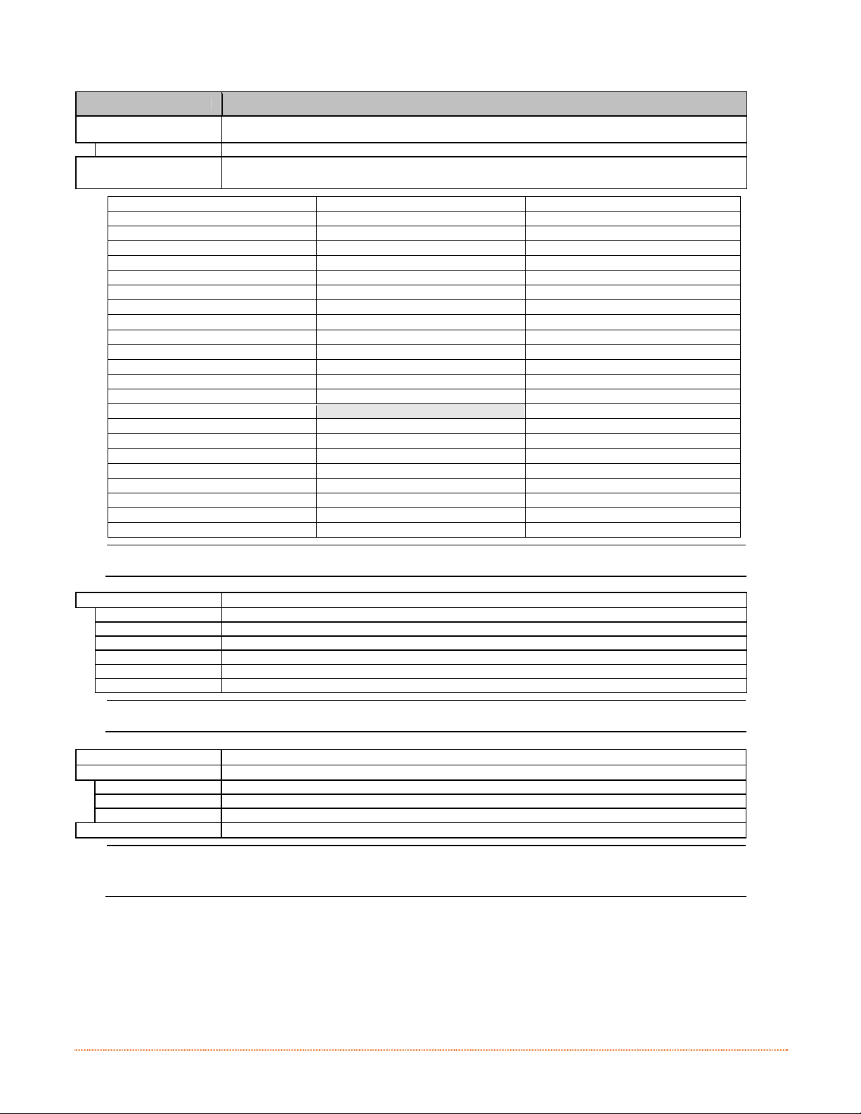
DISPLAYED ITEM ITEM DESCRIPTION
SCALEABLE FONT
CACHE
384 KBytes Is the Default Setting.
SINGLE BYTE SYMBOLS Selects the code page used to print single byte fonts, including:
ARABIC-8 ISO 15: ITALIAN ISO 17: SPANISH
CYRILLIC LEGAL ISO 11: SWEDISH
ISO 60: DAN/NOR HP4000 ZAPF DINGBAT SYMBOL
DESKTOP MATH-8 TURKISH-8
ITC ZAPF DINGBAT/100 MACINTOSH PS TEXT
ITC ZAPF DINGBAT/200 PS-MATH UTF-8
ITC ZAPF DINGBAT/300 PC-858 MULTILINGUAL ISO 4: UK
PS ITC ZAPF DINGBAT MICROSOFT PUBLISHING ISO 6: ASCII
ISO 8859/1 LATIN 1 PC-8 CODE PAGE 437 VENTURA INTERNATIONAL
ISO 8859/2 LATIN 2 PC-8 D/N, CP 437N VENTURA US
ISO 8859/5 LATIN 5 PC-852 LATIN 2 VENTURA MATH
ISO 8859/10 LATIN 6 PC-851 LATIN/GREEK WINDOWS 3.1 LATIN 1
ISO 8859/7 LT/GK E7 PC-862 LATIN/ARABIC WINDOWS LATIN/ARABIC
ISO 8859/15 LATIN 9 PI FONT AGFA TIDBITS
ISO 8859/7 LT/GK EG PC-850 MULTILINGUAL (Default Setting) WINDOWS 3.1 LATIN 2
ISO 8859/8 LATIN/HBR PC-864 LATIN/ARABIC WINDOWS LATIN/GREEK
ISO 8859/8 LATIN/CYR PC-8 TK, CP 437T WINDOWS 3.1 LATIN 5
ISO 69: FRENCH PC-1004 WINDOWS
GREEK-8 PC-775 BALTIC WINDOWS 3.0 LATIN 1
PC-8 GREEK PTXT3000 WINDOWS LATIN/CYRIC
ISO 21: GERMAN NON- UGL, PI FONT WINDOWS 3.0 LATIN 5
HEBREW-7 ROMAN-8
HEBREW-8 ROMAN-9
Reference the Programmer’s Manual for code page symbol set details.
DOUBLE BYTE SYMBOLS Selects the optional ILPC code page used to print double byte fonts, where:
JIS Japanese Industry Standard
SHIFT JIS Shift Japanese Industry Standard
EUC Extended UNIX Code
UNICODE Unicode (including Korean). (Default setting)
GB Government Bureau Industry Standard; Chinese (PRC)
BIG 5 Taiwan encoded
TIME AND DATE Sets the printer's time and date.
MEDIA COUNTERS Displays and controls various internal counters, where:
ABSOLUTE COUNTER Shows the total number of inches printed and the date the counter was set (non-resettable).
RESETTABLE COUNTER Shows the number of inches printed since the last reset (user-resettable).
RESET COUNTER Returns the Resettable Counter to zero.
PRINT CONFIGURATION Produces a Configuration L abel using the printer's current database information.
Reference the Programmer’s Manual for the code page symbol set details.
(1) The information varies with the model, firmware version, and installed options.
(2) To capture all the data, use media that is at least 2 inches (51 mm) wide and set the Label Width (in Media
Settings) according to the width of your labels.
Configures the number of 1KB blocks (128 - 512) allocated for the scaleable font engine, where:
42 Chapter 4 – Menu System
Page 49
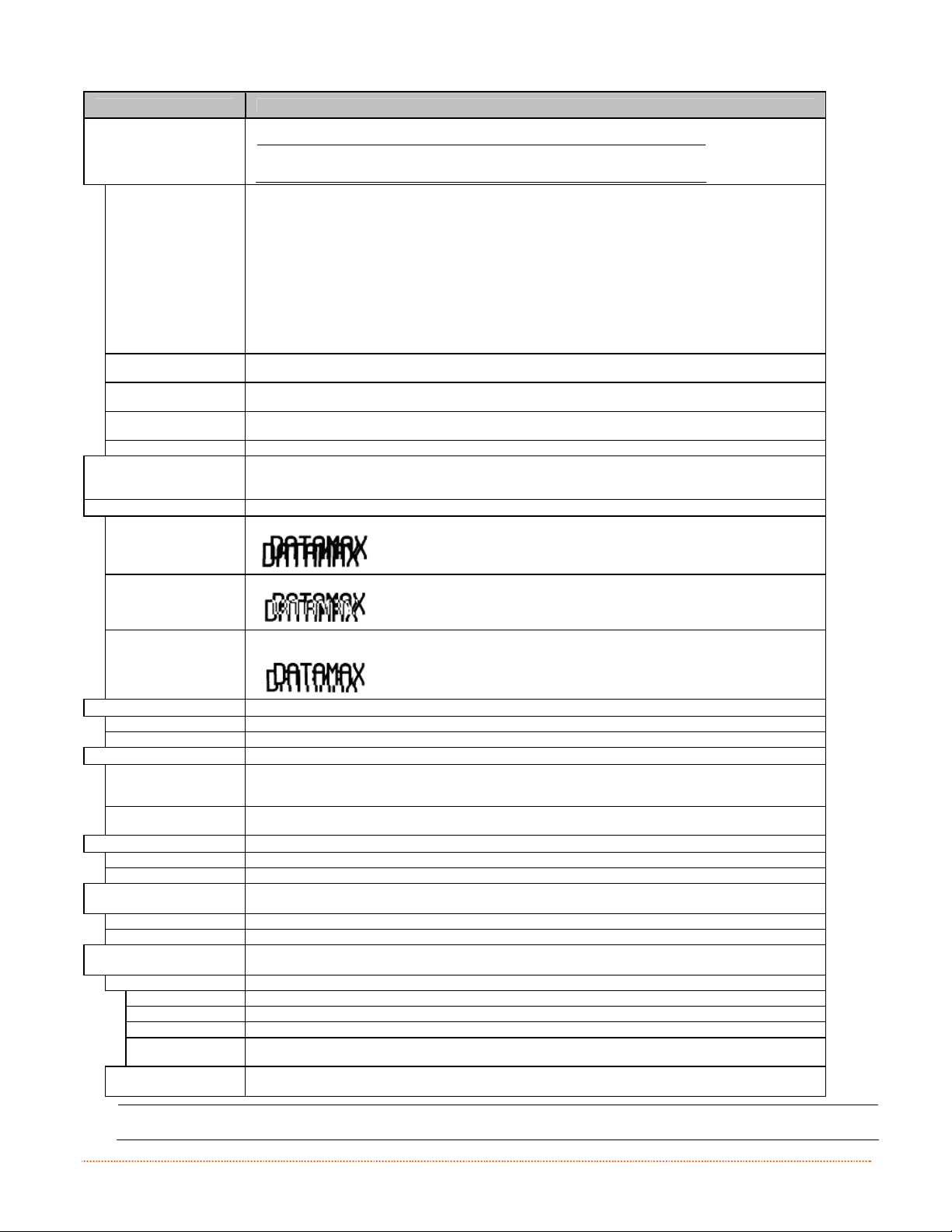
DISPLAYED ITEM ITEM DESCRIPTION
CONFIGURATION LEVEL Displays the hardware and software levels of the printer, where:
PRINTER KEY Identifies the unique key number of the printer, in the form: vvvv-cwxx-yyyyyy-zzz, where:
APPLICATION
VERSION
BOOT LOADER Displays the version level of the boot loaders.
UPGRADE PRINTER
CODE
UNLOCK FEATURE Unlocks additional optional features within the printer. (An authorization code is required.)
SET FACTORY DEFAULTS Returns the printer settings to the factory-programmed values (except CUSTOM ADJUSTMENTS and
FORMAT ATTRIBUTES Defines the manner in which overlapping text and graphics appear when printed, where:
TRANSPARENT Intersecting text, images, and bar codes will be printed, for example:
This information is als o provided on the Configuration Label.
vvvv - Represents the printer model number.
cwxx - Represents the hardware/software feature level, where:
c - Represents the printer class.
w - Represents hardware feature level of the main board.
xx - Represents the software feature level (10 = standard DPL, and 20 = Internal CG Times
yyyyyy - Is the manufacturing date code.
zzz - Is a unique time stamp.
Font). Features are accepted up to this value, but increases beyond the range will
require an authorization code.
Displays the level, version number, and date of the application firmware.
Upgrades the software feature level of the printer.
calibrations); or, if selected, to the Factory Setting File, where selecting YES at the prompt causes
the configuration to be restored.
XOR Intersecting text, images, an d bar codes will not be printed, fo r example:
OPAQUE Intersecting text, images, and bar codes will be printed by obliterating those formatted first, fo r
LABEL ROTATION Allows the label format to be rotated 180 degrees before printing, where:
ENABLED Flips the format.
DISABLED Does not flip the format. (Default Setting)
IMAGING MODE Determines the process used to format labels, where:
MULTIPLE LABEL Images multiple labels as memory permits to achieve the fastest throughput. If time-stamping
SINGLE LABEL Images the next label only after the previous label has been printed, providing the most accurate
PAUSE MODE Allows for controlled interactive printing, where:
ENABLED Requires you to press the PAUSE Key to print each label.
DISABLED Labels are printed without pausing. (Default Setting)
PEEL MODE Allows the printer to wait until the Start of Print signal is received (via the o ptional GPIO Port) to
ENABLED Inhibits the feed function until the Start of Print signal is received.
DISABLED Feeds the label regardless of the Start of Print signal. (Default Setting)
SECURITY Allows all or part of the User Interface to be password-protected and for that password to be
SELECT SECURITY Allows password to be set for specific User Interface areas, where:
DISABLED No password is required for menu access. (Default Setting)
SECURE MENU Sets a password requirement for User and Advanced menu entry.
MENU AND TEST Sets a password requirement for all menu entries.
ADVANCED
MENU
MODIFY PASSWORD Modifies the four-digit password required when security is enabled. For modification, the code must
To be activated, the password must initially be set to a value other than the default setting (0000).
example:
labels, however, the indicat ed time will reflect the moment of imaging rather than the a ctual print
time. (Default Setting)
time-stamps but at a slower throughput rate.
feed a label, where:
modified:
Sets a password requirement for Advanced menu entry. (After enabling this selection, make it
effective by returning the Menu Mode to the User setting; see above.)
be reentered when prompted to confirm.
(Default Setting)
Chapter 4 – Menu System 43
Page 50
DISPLAYED ITEM ITEM DESCRIPTION
UNITS OF MEASURE Sets the measurement standard used, where:
IMPERIAL Uses inches. (Default Setting)
METRIC Uses millimeters and centimeters.
INPUT MODE Defines the type of processing that will occur when data is received, where:
DPL Processes data for standard DPL printing.
LINE Processes data for Line Mode (template) printing.
PL-Z Alternative programming language processing will be used, with the exception of the following DPL
PL-I Processes data for PL-I printing.
PL-B Processes data for PL-B printing.
AUTO Identifies then activates the appropriate emulation parser for the data.
USER LABEL MODE Sets the printer to power-up as default, where:
ENABLED
specific-parameters: DPL Emulation; SOP Emulation; and Label Store.
Functions in standalone mode for quick access to user defined formats.
This mode will remain active until disabled.
DISABLED
DPL EMULATION Allows the printer to reproduce, for back ward compatibility, label formats with the same
STANDARD Standard DPL processing will be used for printing. (Default Setting)
ALLEGRO Processes DPL data as an Allegro®, including row position calculations based on 194 dots per inch
PRODIGY PLUS Processes DPL data as a Prodigy Plus®, including column calculations based on 200 dots per inch
PRODIGY Processes DPL data as a Prodigy®, including column calculations based on 200 dots per inch and the
Functions in normal mode, awaiting commands from a host. (Default Setting)
characteristics as those produced by legacy models, where:
and the exceptions noted below.
and the exceptions noted below.
exceptions noted below.
Exceptions: Data Terminator processing – When printing I 2 of 5 bar codes D, J, and L, the
first non-numeric chara cter processed will terminate the bar code data field.
Bar Size exception – When printing I 2 of 5 bar code L, if the bar size specified is
greater than P (25) it is automatically decreased to 10.
Human Readable Fonts fixed size – When printing EAN and UPC bar codes B, C, F,
G, M, and N, a fixed font size is produced.
Line and box vertical sizing anomaly – When printing rotations 2 and 4, lines and
boxes are affected by the vertical multiplication factor defined in the DPL Dxx
command.
Column position defaults – Column positions greater than the printhead width are
adjusted back to the printable area then printed.
Bar codes in rotation 3 - (upside down / right to left) default sizing – When row
position in rotation 3 is less than bar code height, bar codes falling off the label's
leading edge are pushed back onto the label.
<STX>L command – When no printable fields reside in the format, it results in no
label movement.
44 Chapter 4 – Menu System
Page 51

DISPLAYED ITEM ITEM DESCRIPTION
COLUMN EMULATION Allows the column dots per inch to be adjusted (153 - 253 dots), so that numbers smaller than the
XXX Dots Default setting is dependant on printer model.
ROW EMULATION Allows the row dots per inch to be adjusted (103 - 303), so that numbers smaller than the printhead
XXX Dots Default setting is dependant on printer model.
SOP EMULATION Allows label positioning commands to function with backward compatibility when printin g label
DISABLED Produces the natural start of print position. (Default Setting)
110 (PRODPLUS) Emulates the Prodigy Plus® start of print position.
220 (ALLEGRO) Emulates the Allegro® start of print position.
250 (PRODIGY) Emulates the Prodigy™ start of print position.
BACK AFTER PRINT Determines media movement when a cutter, present sensor, peel and present, or GPIO is enabled,
MODE
DISABLED Movement occurs only when the next label is ready to print, minimizing edge curling. (Default
ENABLED
BACKUP DELAY
(1/50s)
000 Retraction occurs when the next label is received and processed. (Default Setting)
FONT EMULATION Allows font substitution for all internal fonts where:
STANDARD FONTS Prints using a standard (internal) font. (Default Setting)
CG TIMES Prints using the CG Times font.
USER ID S50 Prints using a downloaded font.
LABEL STORE Deter mines the command recall level used when retrieving stored label formats, where:
STATE & FIELDS Recalls the printer state (i.e., heat, speed settings, etc.) and the label-formatting commands for the
FIELDS ONLY Recalls the label-formatting commands for the stored label.
MENU LANGUAGE Selects the menu and configuration label language. Only languages that are resident will be
ENGLISH Enables English (Default Setting)
DISPLAY SETTINGS
GRAPHIC DISPLAY
MODE
STANDARD
ENHANCED Is the enlarged setting.
DISPLAY UNITS Determines the displayed type of distance information, where:
STANDARD Displays the information according to the UNITS OF MEASURE setting (see above).
IMPERIAL Displays the information in inches.
METRIC Displays the information in millimeters and centimeters.
DISPLAY BACKLIGHT Controls the mode and “ON” time of the display’s backlight
BACKLIGHT MODE Sets the mode in which the b acklight is activated. Choices are Always On, Always Off, or Auto.
AUTO ON TIME Set the amount of time t he bac klight will remain on. BA CKLIGH T MODE (see a bove) must b e set to auto .
DISPLAY CONTRAST Adjusts the displays contrast (0-100), where:
50 Is the default setting
FAULT HANDLING Determines the intervention required and the disposition of the label in pro cess when a fault occurs,
LEVEL Selects the user action and the reprint status upon declaration of a fault, where:
NO REPRINT Printing stops and a fault message is displayed. Following correction of the problem, the FEED Key
STANDARD Printing stops and a fault message is displayed. Following correction of the problem, the FEED Key
BUZZER Sets a scalable font boldfacing amount, where:
ENABLED Enables the printers buzzer. (Default Setting)
DISABLED Disables the printers buzzer.
SCL FONT BOLD FACTOR Sets a scalable font boldfacing amount, where:
08 (1 – 36) Is the setting, based on an incrementing scale, where eight (08) is nominal.
printhead resolution reduce the printed output from right to left, where:
resolution enlarge the height of the printed output and numbers larger reduce it, where:
formats designed for legacy models, where:
where:
Repositions media, where:
Setting)
Movement occurs according to BACKUP DELAY timing after a cut, cleared sensor, or SOP to allow
fastest throughput.
Instructs the printer to retract a presented label after a specified time elapses (0 – 255, in onefiftieth of a second increments), where:
stored label. (Default Setting)
displayed (see Appendix D), where:
Determines the appearance of the items in the display, where:
Determines the magnification of the displayed items, where:
Is the normal setting.
where:
must be pressed to clear the fault, but the label in process is not r eprinted.
must be pressed to clear the fault then the label in process is reprinted. (Default Setting.)
Chapter 4 – Menu System 45
Page 52
Communications
The Communications menu contains interface and host control functions:
Serial Port A*
Parallel Port A*
USB Port*
Network/Bluetooth*
Host Settings*
Items denoted with an asterisk (*) are only accessible through the Advanced Menu.
The menu selections are defined as follows:
DISPLAYED ITEM ITEM DESCRIPTION
SERIAL PORT A Controls the RS-232 communications settings for Serial Port A, where:
BAUD RATE Sets the serial communication rate, where:
(1200 – 115KBPS)
9600 BPS
PROTOCOL Sets the data flow control (handshaking) method, where:
BOTH XON/XOFF and CTS/DTR are used. (Default Setting)
SOFTWARE XON/XOFF is used.
HARDWARE CTS/DTR is used.
NONE Flow control is not used.
PARITY Sets word parity, where:
NONE Parity is not used. (Default Setting)
ODD Odd parity is used.
EVEN Even parity is used.
DATA BITS Sets word length, where:
(7 - 8)
8
STOP BITS Sets the number of stop bits, where:
(1 - 2)
1
PARALLEL PORT A Controls the communication setting for the parallel port, where:
PORT DIRECTION Determines if data is returned from the printer, where:
UNI-DIRECTIONAL No data is returned; communication is one-way.
BI-DIRECTIONAL Data is returned in compliance with IEEE 1284 back-channel operation. (Default Setting)
Is the range, in Bits Per Second; and,
is the Default Setting.
A seven or eight bit word is selectable; and,
is the Default Setting.
One stop or two stop bits are selectable; and,
is the Default Setting.
USB PORT Controls the communication setting for the USB port
USB DEVICE CLASS Defines the USB port type
PRINTER Sets the printer for use as a typical Windows printer
CDC Sets the printer for use with handled PC’s and similar devices
COMPOSITE Combines both Printer and CDC classes. (Default Setting)
An IEEE 1284 bidirectional cable is required.
46 Chapter 4 – Menu System
Page 53

DISPLAYED ITEM ITEM DESCRIPTION
NETWORK/BLUETOOTH Controls the communications settings for the network and Bluetooth interfaces, where:
ACTIVE INTERFACE Selects the network interface currently in use by the printer, where:
NONE Disables all interfaces
WIRED
ETHERNET
WIRELESS
ETHERNET
BLUETOOTH Selects the Bluetooth interface (if installed)
WIRED ETHERNET Controls the communications settings for the wired Ethernet network interface
IP DISCOVERY Sets the address discovery method, where:
USE STATIC
ADDRESSES
USE DHCP The card broadcasts over the network using DHCP protocol to receive addresses from the
USE BOOTP The card broadcasts over the network using BOOTP protocol to receive addresses from the
STATIC IP
ADDRESS
STATIC SUBNET
MASK
STATIC
GATEWAY
DUPLEX
CAPABILITY
Selects the Wired Ethernet interface
Selects the Wireless Ethernet interface (if installed)
The stored static IP, Subnet Mask, and / or Gateway Address will be used.
responsible server at startup. Manual modifications to IP Address, Subnet Mask, or Gateway Address
are not allowed; and, if no server is found, the specified static value will be used. (Default Setting)
responsible server at startup. Manual modifications to IP Address, Subnet Mask, or Gateway Address
are not allowed; and, if no server is found, the specified static value will be used. (Default Setting)
Specifies the static IP Address of the interface in the standard octet format.
Specifies the static Subnet assigned to the interface, for example:255.255.255.000.
Specifies the Gateway Address th e interface will use, for example:192.168.10.1
Specifies the transmission and speed of the wired Ethernet connection:
A server assigned IP address takes precedence over any static IP address
stored in the interface.
A server assigned IP address takes precedence over any static IP address
stored in the interface.
• Auto-Negotiate (default);
• 10 BaseT Half Duplex
• 10 BaseT Full Duplex
• 100 BaseT Half Duplex
• 100 BaseT Full Duplex
PRIMARY WINS
SERVER
SECONDARY
WINS SERVER
PRIMARY DNS
SERVER
SECONDARY
DNS SERVER
SNMP TRAP
ADDRESS
SNMP SERVER
ADDRESS
NETBIOS
ENABLE
NO (Default Setting)
YES
TCP PRINT PORT Selects the Port to use for all TCP network communications; Default is 9100
INACTIVITY TIME Set the amount of time (in seconds) in which the current port will remain open when no activity is
LPD PRINT PORT Selects the Port to use for all LPD network communications; Default is 515
The IP address of the primary WINS Server.
The IP address of the secondary WINS Server.
The IP address of the primary DNS Server.
The IP address of the secondary DNS Server.
Is the address in standard octet format where SNMP traps will be sent when SNMP service is
installed on your receiver. When zeroed, no traps are sent.
Is the server address in standard octet format for SNMP services.
Enables or disables the NET BIOS SERVICES
present.
Chapter 4 – Menu System 47
Page 54

DISPLAYED ITEM ITEM DESCRIPTION
WIRELESS ETHERNET Controls the communications settings for the wireless Ethernet network interface, where:
IP DISCOVERY Sets the address discovery method, where:
USE STATIC
ADDRESSES
USE DHCP The card broadcasts over the network using DHCP protocol to receive addresses from the
USE BOOTP The card broadcasts over the network using BOOTP protocol to receive addresses from the
STATIC IP
ADDRESS
STATIC SUBNET
MASK
STATIC
GATEWAY
BLUETOOTH Controls the communications settings for the Bluetooth network interface, where:
DISCOVERABLE Yes/No; Determines whether other Bluetooth devices in range can detect the printer.
CONNECTABLE Yes/No; Determines whether other Bluetooth devices in range can connect to the printer.
BONDABLE Yes/No; Determines whether other Bluetooth devices in range can create a “bondable” connection
AUTHENTICATION
REQUIRED
ENCRYPTION Yes/No; Determines whether encryption is used during data transfer to the printer.
INACTIVE
DISCONNECT
TIME
POWER DOWN
TIME
GENERAL NETWORK Controls general communication parameters, where:
SNMP ENABLE Sets SNMP
NO (Default Setting)
YES
TELNET ENABLE Enable/Disable Telnet protocol
NO (Default Setting)
YES
FTP SERVER
ENABLE
NO (Default Setting)
YES
HTTP SERVER
ENABLE
NO
YES (Default Setting)
LPD PRINT
ENABLE
NO
YES (Default Setting)
TCP PRINT
ENABLE
NO
YES (Default Setting)
NETCENTER
ENABLE
NO (Default Setting)
YES
GRATUITOUS ARP
NETWORK REPORT
The stored static IP, Subnet Mask, and / or Gateway Address will be used.
responsible server at startup. Manual modifications to IP Address, Subnet Mask, or Gateway Address
are not allowed; and, if no server is found, the specified static value will be used. (Default Setting)
responsible server at startup. Manual modifications to IP Address, Subnet Mask, or Gateway Address
are not allowed; and, if no server is found, the specified static value will be used. (Default Setting
Specifies the static IP Address of the interface in the standard octet format.
Specifies the static Subnet assigned to the interface, for example:255.255.255.000.
Specifies the Gateway Address th e interface will use, for example:192.168.10.1
with the printer
Yes/No; Determines whether passkey is required to the printer.
(0-65535 in seconds); Default: 60
Set the amount of time (in seconds) in which the current connection will remain open when no
activity is present.
(0-65535 in seconds); Default: 60
Set the amount of time (in seconds) in which the Bluetooth module will remain on when no a ctivity
is present.
Enable/Disable FTP protocol
Enable/Disable FTP protocol
Enable/Disable LPD protocol
Enable/Disable TCP protocol
Enable/Disable Netcenter c ompatibility
Sets time interval for ARP transmission packets, where:
(0-100 minutes); Default is 0
Print or view on screen the printers network information.
A server assigned IP address takes precedence over any static IP address
stored in the interface.
A server assigned IP address takes precedence over any static IP address
stored in the interface.
)
48 Chapter 4 – Menu System
Page 55

DISPLAYED ITEM ITEM DESCRIPTION
HOST SETTINGS Controls the communications with a host device, where:
The "ignore host" settings for ESC SEQUENCES, HEAT, SPEED, TOF SENSING,
HOST TIMEOUT Sets the number of seconds (1 - 60) that an established communications port must be idle before
10 Is the Default Setting.
CONTROL CODES Allows changes to the prefix of the software commands interpreted by the printer, where:
STANDARD
CODES
ALTERNATE
CODES
ALTERNATE
CODES 2
CUSTOM CODES Each DPL command (SOH, STX, CR, and count-by) may be selected by entering the desired Hex
FEEDBACK
CHARACTERS
ENABLED Sends feedback characters to the host.
DISABLED Does not send feedback characters to the host. (Default Setting)
ESC SEQUENCES Allows data containing invalid ESC control code sequences to be processed, where:
ENABLED Processes commands normally. (Default Setting)
DISABLED Ignores ESC sequences are during processing (since some systems send a “banner” to the printer).
HEAT COMMAND Determines the way the DPL Heat command is handled, where:
ENABLED Processes commands normally. (Default Setting)
DISABLED Ignores DPL Heat commands; instead, the heat value is controlled via the menu setting.
SPEED COMMANDS Determines the way DPL Print, Feed, Slew, and Reverse commands are handled, where:
ENABLED Processes commands normally. (Default Setting)
DISABLED Ignores DPL speed commands; instead, the speeds are controlled via the menu setting.
TOF SENSING
COMMANDS
ENABLED Processes commands normally. (Default Setting)
DISABLED Ignores DPL TOF commands; instead, TOF is controlled via the menu setting.
SYMBOL SET
COMMAND
ENABLED Processes commands normally. (Default Setting)
DISABLED Ignores DPL Symbol Set commands; instead, the Symbol Set selection is controlled via the menu
CNTRL-CODES
(DATA)
ENABLED Processes commands normally. (Default Setting)
DISABLED Ignores DPL Control Codes; instead, the control code functions are established via the menu setting.
STX-V SW SETTINGS Determines the way in which the DPL <STX>V command is handled, where:
ENABLED Processes commands normally. (Default Setting)
DISABLED Ignores the option-enable command; instead, the option selections are controlled via menu settings.
MAX LENGTH
COMMAND
ENABLED Processes commands normally. (Default Setting)
DISABLED Ignores the maximum label length command; instead, Maximum Label Length is controlled via the
PROCESS SOH
(DATA)
ENABLED Operations are interrupted upon receipt to process the command.
DISABLED Processes commands normally. (Default Setting)
data can be received through an alternate port, where:
Use these characters: Hex 01 = SOH command; Hex 02 = STX command; count-by = ^; Hex 1B =
ESC; Hex 0x0D = Carriage Return. (Default Setting)
Use these characters: Hex 5E = SOH command; Hex 7E = STX command; count-by = @; Hex 1B =
ESC; Hex 0x0D = Carriage Return.
Use these characters: Hex 5E = SOH command; Hex 7E = STX command; count-by = @; Hex 1B =
ESC; Hex 0x7C = Carriage Return.
code.
Allows the printer to return a Hex 1E (RS) after each label successfully prints, and a Hex 1F (US)
after each label batch successfully prints, where:
Bitmapped font downloads are disabled in this mode.
Determines the way in which DPL Gap, Continuous, and Reflective commands are handled, where:
Determines the way in which DPL Single and Double Symbol Set commands are handled, where:
setting.
Determines the way in which DPL SOH, STX, CR, ESC, and ^ codes are handled, where:
Determines the way in which th e DPL <STX>M command is handled, where:
menu setting.
Determines the way the printer responds to an Immediate Command (e.g., Get Status, Module
Storage, etc.), where:
SYMBOL SET, CNTRL-CODES, STX-V SW SETTINGS, and MAX LENGTH will be
unaffected when PL-Z Mode is selected (see Input Mode for details).
If the time-out period is exceeded before all data is received, th e data will be
ignored.
Chapter 4 – Menu System 49
Page 56
Diagnostics
The Diagnostics menu contains testing functions and printhead reporting selections:
Hex Dump Mode*
Options Testin g*
Print Test Rate (min )*
Sensor Readings*
Ribbon Sensor Limits*
Items denoted with an asterisk (*) are only accessible through the Advanced Menu.
The menu selections are defined as follows:
DISPLAYED ITEM ITEM DESCRIPTION
HEX DUMP MODE Determines how the printer handles the data received from a host, where:
ENABLE The printer outputs the raw ASCII data it receives without interpretation; no processing occurs.
DISABLE Processes data normally. (Default Setting)
FILE CAPTURE Saves the incoming data to Module H (USB thumbdrive) if present; otherwise, the file is stored on
OPTIONS TESTING Performs printer option diagnostics or monitors and outputs test results, where:
TEST PRESENT
SENSOR
TEST CUTTER Performs a functional test of the Cutter, where:
PERFORM TEST
001 TIMES
PRINT TEST RATE (MIN) Sets a label-to-label delay interval (0 - 120 minutes) when Test label batch printing, where:
000 Is the Default Setting.
SENSOR READINGS
RIBBON SENSOR LIMITS Displays the values from the ribbon sensor readings (see example below) for printers equipped with
FLASH MODULE REPORT Displays the module report data, where:
VIEW Displays the data.
PRINT Prints a reference label:
Flash Module Report*
Module G. The file name, in the form [dmx_xxx_yyy.dpl], where the count is automatically
incremented for every capture and a unique printer time stamp (xxx), is assigned.
Performs a functional test of the Present Sensor by indicating LABEL PRESENTED (when a label
blocks the sensor) and LABEL NOT PRESENTED (when no label blocks the sensor). (Note that this
test can also be used to check the sensor function of the Peel & Present option.)
Cycles the cutter blade a selected number of times (0 - 999), with PASS / FAIL results given for
each cycling attempt.
Displays the values (0 – 255) from the printer sensors, where:
THR = Printhead thermistor sensor;
TRAN = Gap media sensor (REFL when set to reflective);
RIBM = Ribbon sensor;
24V = 24 volt power supply sensor;
PS = Present sensor;
HD = Printhead position sensor; and,
RANK = Printhead ranking resistor.
the thermal transfer option, where:
THR TRAN RIBM 24V
103 091 009 171
PS HD RANK
003 255 050
RIBBON ADC LOW
111
RIBBON ADC HIGH
249
FLASH MODULE REPORT
SUN 12:44PM 23MAY2011
Module G Mount Fail: 0
Module G Reformatted: 0
50 Chapter 4 – Menu System
Page 57

&
&
&
e
c
n
a
n
e
t
n
i
A
A
A
c
t
c
t
c
t
a
i
a
i
a
d
d
d
i
o
n
i
o
n
i
o
n
Turn OFF the printer before cleaning the printhead.
Use solvent* applied with a cotton swab to clean
the printhead from end to end.
Turn OFF the printer. Rotate the platen roller and
clean it thoroughly with solvent* applied with a
cotton swab.
Rotate the peel-off roller and clean it thoroughly
with solvent* applied with a cotton swab.
n
n
u
j
u
j
u
j
t
t
e
e
s
s
s
n
n
t
t
t
m
m
m
a
a
n
n
e
e
e
n
c
c
n
n
e
e
s
t
s
t
s
t
After every roll of media.
After every roll of media.
After every roll of media.
M
M
M
5
5
5
5
.
1
5
.
1
5
.
This section details the cleaning, adjusting, and troubleshooting tips for the printer. The following table
outlines the recommended maintenance schedule for the various printer parts.
I
n
I
n
1
I
n
Printhead
Platen Roller
Peel-Off Roller
t
r
o
d
t
t
u
r
o
d
u
r
o
d
u
Area Method Interval
Media Path Solvent* After every roll of media.
Peel/Tear Bar Solvent* As needed
Media Sensor Blown air or brush Monthly
Exterior Mild detergent or desktop cleaner. As needed
Interior Brush or vacuum cleaner As needed.
* A solvent containing isopropyl alcohol is recommended for use.
Isopropyl alcohol is a flammable solvent; always take the proper precautions when in use.
Chapter 5 – Maintenance and Adjustments 51
Page 58

5
.
2
C
l
e
a
n
i
n
g
t
h
e
P
r
i
n
t
h
e
a
d
5
5
.
2
C
l
e
a
n
i
n
g
t
h
e
P
r
i
n
t
.
2
C
l
e
a
n
i
n
g
t
h
e
P
Never use a sharp, hard, or abrasive object on the printhead.
h
r
i
n
t
h
e
e
a
a
d
d
If print quality declines (symptoms can include unreadable bar codes or streaks through text and graphics),
the typical cause is debris buildup on the printhead which, left unattended, can lead to premature dot failure.
Depending upon the supplies and printing parameters used, different cleaning methods are recommended.
Proper cleaning is critical. To maintain peak performance of the printer,
Datamax-O’Neil offers a complete line of cleaning products including
pens, cards, films and swabs. To learn more visit our website
Cotton Swab Procedure
If printing with direct thermal media or thermal transfer media with wax ribbon, clean the pri nthead as
follows:
1) Turn OFF the power switch and unplug the printer. Open the printer. Wait briefly for the
printhead to cool.
2) Remove any installed media and ribbon. Using a Cotton Swab moistened (not soaked) with
isopropyl alcohol, thoroughly clean the Printhead.
312
Streaks can indicate a dirty or a faulty printhead.
.
Cotton Swab with Solvent
Printhead
52 Chapter 5 – Maintenance Adjustments
Page 59

Cleaning Card Procedure
If printing with direct thermal media, thermal transfer media with wax/resin ribbon combinations, or if the
Cotton Swab technique was not successful, clean the printhead as follows:
1) Open the printer. Wait briefly for the Printhead to cool.
2) Remove media and ribbon then place a Cleaning Card under the Printhead (part number 70-2013-
01).
3) Close the cover then press the button to initiate cleaning.
4) After the cleaning card has been run through the printer, reinstall media (and ribbon, if needed).
Plug in and turn ON the printer. Run a few sample labels and examine them. If streaking is still
present, use the Cleaning Film Procedure, below; otherwise, this completes cleaning.
Cleaning Film Procedure
If printing with thermal transfer media and resin ribbon, when printing with a Heat Val ue of 22 or higher, or
when other methods prove unsuccessful, clean the printhead as follows:
1) Open the printer. Wait briefly for the Printhead to cool..
2) Remove media and ribbon then place a sheet of Cleaning Film under the Printhead (part number
70-2087-01).
3) Close the cover then press
4) After the cleaning film has been run through the printer, turn OFF the Power Switch and unplug
the printer. Open the cover and wait briefly for the Printhead to cool. Using a cotton swab
moistened (not soaked) with isopropyl alcohol, clean the Printhead then allow it to dry.
5) Reinstall media (and ribbon, if needed). Plug in and turn ON the printer. Run a few sample labels
and examine them. If streaking is still present, the Printhead may need to be replaced; see
Section 5.5
button to initiate cleaning.
Chapter 5 – Maintenance and Adjustments 53
Page 60

5
.
3
R
i
b
b
o
n
T
e
n
s
i
o
n
A
d
j
u
s
t
m
e
n
t
5
.
3
R
i
b
b
o
n
T
e
n
s
i
o
n
A
d
j
u
s
t
5
.
3
R
i
b
b
o
n
T
e
n
s
i
o
n
A
d
The adjustable ribbon handler feature, found on printers equipped with the thermal transfer option, allows the
optimum amount tension to be supplied by the ribbon supply hub. Adjust the ribbon tension as follows:
1) Turn ‘off’ the printer.
2) Hold the ribbon/ribbon hub to prevent it from turning. Then push in and rotate the Ribbon Tension
Adjustment Knob to the position that matches the core size of the ribbon in use.
312
m
j
u
s
t
m
e
e
n
n
t
t
Ribbon Handler
Ribbon Tension Adjustment Knob
54 Chapter 5 – Maintenance Adjustments
Page 61

5
.
4
A
d
j
u
s
t
a
b
l
e
M
e
d
i
a
S
e
n
s
o
r
5
.
4
A
d
j
u
s
t
a
b
l
e
M
e
d
i
a
S
e
5
.
4
A
d
j
u
s
t
a
b
l
e
M
e
d
i
a
The optional Adjustable Media Sensor (AMS) allows the printer to accept a wider variety of media
configurations. The table below defines general AMS positions for various media and Top of Form (TOF) types.
Media Type
Continuous
Die-Cut
Notched/Hole
Black Bar
Position the AMS as follows:
1) On the Bottom AMS Sensor, identify the proper Indicator for
use with your media.
Gap or Notch Indicator
Reflective (Mark) Indicator
crosses the sensors. (top and bottom
n
S
e
n
Any location in the media path with
both sensors aligned.
Any location within the media path
where the gap between the labels
sensors must be aligned)
Center of the Notch or Hole
Center of the Black Mark Reflective
s
o
r
s
o
r
AMS Positioning
Sensor Location TOF Sensing Method
(Only detects out of media)
Continuous
Separate Die Cut and
Notched. Use this for the
Notched or Hole Media
Gap (primary)
Reflective (secondary)
2) Slide the Bottom AMS sensor so the Indicator is in line with the center of the notch, gap, or
reflective (mark) of the installed media.
3) Slide the Top AMS Sensor over to the same
necessary if using reflective media).
312
setting as the Bottom AMS Sensor, (this is not
Bottom AMS Sensor
Top AMS Sensor
4) Load media, see Section 2.3.
Chapter 5 – Maintenance and Adjustments 55
Page 62

5
.
5
P
r
i
n
t
h
e
a
d
R
e
p
l
a
c
e
m
e
n
t
5
.
5
P
r
i
n
t
h
e
a
d
R
e
p
l
a
c
e
5
.
5
P
r
i
n
t
h
e
a
d
R
e
p
l
If the Printhead becomes damaged or worn, replace it as follows:
a
c
e
m
m
e
e
n
n
t
t
Always follow proper Electro Static Discharge procedures when replacing the printhead.
1) Turn OFF the printer and remove the ribbon if installed.
2) Lower the Ribbon Handler Assembly.
3) Press outward on the two Printhead Carrier Tabs and rotate the Printhead Carrier down.
312
Ribbon Handler
Printhead Assembly Tabs
Printhead Carrier
4) Press inward on the two Printhead Shield Tabs and rotate the Printhead Shield down.
312
Printhead Shield Tabs
56 Chapter 5 – Maintenance Adjustments
Page 63

5) Loosen the Printhead Screw and allow the Printhead to fall free.
6) Remove the Printhead Cable.
312
Printhead Shield
Printhead Screw
Printhead
Printhead Cable
Sensor
Installation:
1) Carefully connect the Printhead Cable to the new Printhead.
2) Position the Printhead in the Printhead Carrier and tighten the Printhead Screw.
3) Ensure the Sensor properly seated and rotate the Printhead Shield upward until it snaps into
place.
4) Rotate the Printhead Carrier upward until it snaps into place.
Chapter 5 – Maintenance and Adjustments 57
Page 64

5
.
6
P
l
a
t
e
n
R
o
l
l
e
r
R
e
p
l
a
c
e
m
e
n
t
5
.
6
P
l
a
t
e
n
R
o
l
l
e
r
R
e
p
l
a
c
e
5
.
6
P
l
a
t
e
n
R
o
l
l
e
r
R
e
p
l
The Platen Roller can be easily removed for cleaning, replacement, or clearing media jams.
1) Turn OFF the printer and remove the media if installed.
2) Lift up on the two Platen Roller Tabs.
312
a
c
e
m
m
e
e
n
n
t
t
Platen Roller T abs
3) Remove the Platen Roller Assembly from the printer.
Installation:
1) Position the Platen Roller Assembly into the printer.
2) Rotate the two Platen Roller Tabs downward until they snap into place.
312
Platen Roller Assembly
58 Chapter 5 – Maintenance Adjustments
Page 65

5
.
7
U
p
d
a
t
i
n
g
F
i
r
m
w
a
r
e
5
.
7
U
p
d
a
t
i
n
g
F
i
r
m
5
.
7
U
p
d
a
t
i
n
g
F
When program updates and/or new features are added, they can be downloaded to the printer as
follows:
1) Identify the new version for your model of printer from the Datamax-O’Neil Web site at
www.datamax-oneil.com and download it onto your computer’s hard drive.
2) Launch the NETira CT configuration utility, and query (connect) to the printer, (see section 3.5 for
more information on NETira CT).
It is recommended that the configuration be saved before downloading firmware, and restored when
3) Go to the Tools>Upgrade>Firmware.
4) Click the ‘Send’ button to start the
5.7.1 Boot 1 and Boot 2 Boot Loaders
1) Connect the printer to your PC using a serial cable
2) Launch the NETira CT configuration utility, and query (connect) to the printer, (see section 3.5 for
3)
4) Check the “Select and Download Boot 1 file:”, “Select and Download Boot 2 file:” and “Erase System
finished. Be sure to check the box labeled “Include Sensor Calibration Data on Open” when restoring
the configuration.
Select the binary file (BIN file).
firmware update.
more information on NETira CT).
It is recommended that the configuration be saved before downloading firmware, and restored when
finished. Be sure to check the box labeled “Include Sensor Calibration Data on Open” when restoring
the configuration.
Go to the Tools>Upgrade>Firmware. Select the binary files (BIN files) for each of the Boot files.
and/or User Area” boxes and click send to initiate the download.
Always Check “Erase System and/or User Area” box unless otherwise instructed..
w
i
r
m
w
a
a
r
e
r
e
5) Once the Boot Loader files have been loaded, the firmware version can now be updated using the
procedure outlined in section 5.7.
Chapter 5 – Maintenance and Adjustments 59
Page 66

60 Chapter 5 – Maintenance Adjustments
Page 67

g
n
i
t
o
o
h
s
e
l
b
u
o
r
T
T
T
6
6
6
6
.
1
6
.
1
6
.
Occasionally, situations arise that require troubleshooting. Possible problem situations and potential solutions
are listed below. Contact a qualified technician for problems that persist or problems not covered in this
section.
6
.
2
6
.
2
6
.
The following section lists the symptoms and the associated page numbers of the topics covered. While not
every situation is addressed, you may find some tips helpful. After a correction action is taken press the FEED
Button to clear the alarm.
Unacceptable print quality:
The printer does not print or prints several labels at once:
The ribbon does not advance (the paper advances, but ribbon does not):
I
n
t
r
o
d
u
I
n
t
1
2
r
I
n
t
r
T
r
o
u
T
r
o
u
T
r
o
u
Dirty printhead: Clean the printhead (see Section 5.2).
The temperature setting may be incorrect for the media being used: Use the software program or
DPL commands adjust the Heat Setting and Print Speed.
A mismatched incorrect ribbon/media combination is being used: Check the types being used.
Faulty printhead: Replace it (see Section 5.5) or call for service.
The labels are incorrectly loaded: See the loading instructions on the inside cover of the printer, or
in Section 2.3.
The media is not calibrated: Calibrate it (see Section 3.7).
The media sensor or sensor circuitry may be defective: Call for service.
The ribbon may be installed incorrectly: Ensure that the inked side of the ribbon faces the labels.
With most ribbons this can be verified by rubbing paper against the ribbon; the ink should smudge
the paper. Or, if using label stock, the sticky side of a label will pull off the ink.
A mismatched ribbon/paper combination is resulting in an insufficient amount of friction between
paper and ribbon: Ensure that the correct type of ribbon is being used with the media.
o
o
b
b
b
d
d
c
u
c
u
c
l
e
s
l
e
s
l
e
s
t
t
h
h
t
h
r
r
i
o
i
o
i
o
o
o
o
o
o
n
n
n
o
t
o
t
o
t
i
n
i
n
i
n
u
u
g
T
g
T
g
T
b
b
i
p
i
p
i
p
s
s
s
l
l
e
e
s
s
h
h
o
o
o
o
t
t
i
i
n
n
g
g
Chapter 6 – Troubleshooting 61
Page 68

Skips every other label (print quality is good, but every other label is skipped):
The label is formatted too close to the top edge of the label: Leave white space equal to 8-dot
rows (about .02 inch [.5mm]) at the top of the label.
The media is not calibrated: Calibrate it (see Section 3.7).
The media sensor or media sensor circuitry may be defective: Call for service.
Unable to print rotations:
The characters are formatted outside the dimensi o ns of the label: Check that the row/column
values provide enough room for the height of the image being printed.
Light print on the right side of the label:
The printer’s cover is not latched down: Latch it.
The printhead is not properly aligned: Call for service.
Printer fails to power ON:
Label advances 1-2 inches before a fault indication:
Label advances 12 inches before a fault indication:
Labels move excessively from side to side during printing:
The AC wall outlet may be faulty: Try another outlet.
The power supply may be faulty: Replace it.
Possible defective power switch: Call for service.
The ribbon may be incorrectly installed. Ensure that the inked side of the ribbon faces the labels.
With most ribbons this can be verified by rubbing paper against the ribbon; the ink should smudge
the paper. Or, if using label stock, the sticky side of a label will pull off the ink.
A mismatched ribbon/paper combination is resulting in an insufficient amount of friction between
paper and ribbon: Ensure that the correct type of ribbon is being used with the media.
The media may not be properly loaded: Reload it (see Section 2.3). When loading media ensure
that the media hangers and media guides are against the media and that gaps or marks in the
labels are in line with the media sensor.
The media sensor or media sensor circuitry may be defective: Call for service.
The media may not be properly loaded: Reload it (see Section 2.3). When loading media ensure
that the media hangers and media guides are against the media and that gaps or marks in the
labels are in line with the media sensor.
62 Chapter 6 – Troubleshooting
Page 69
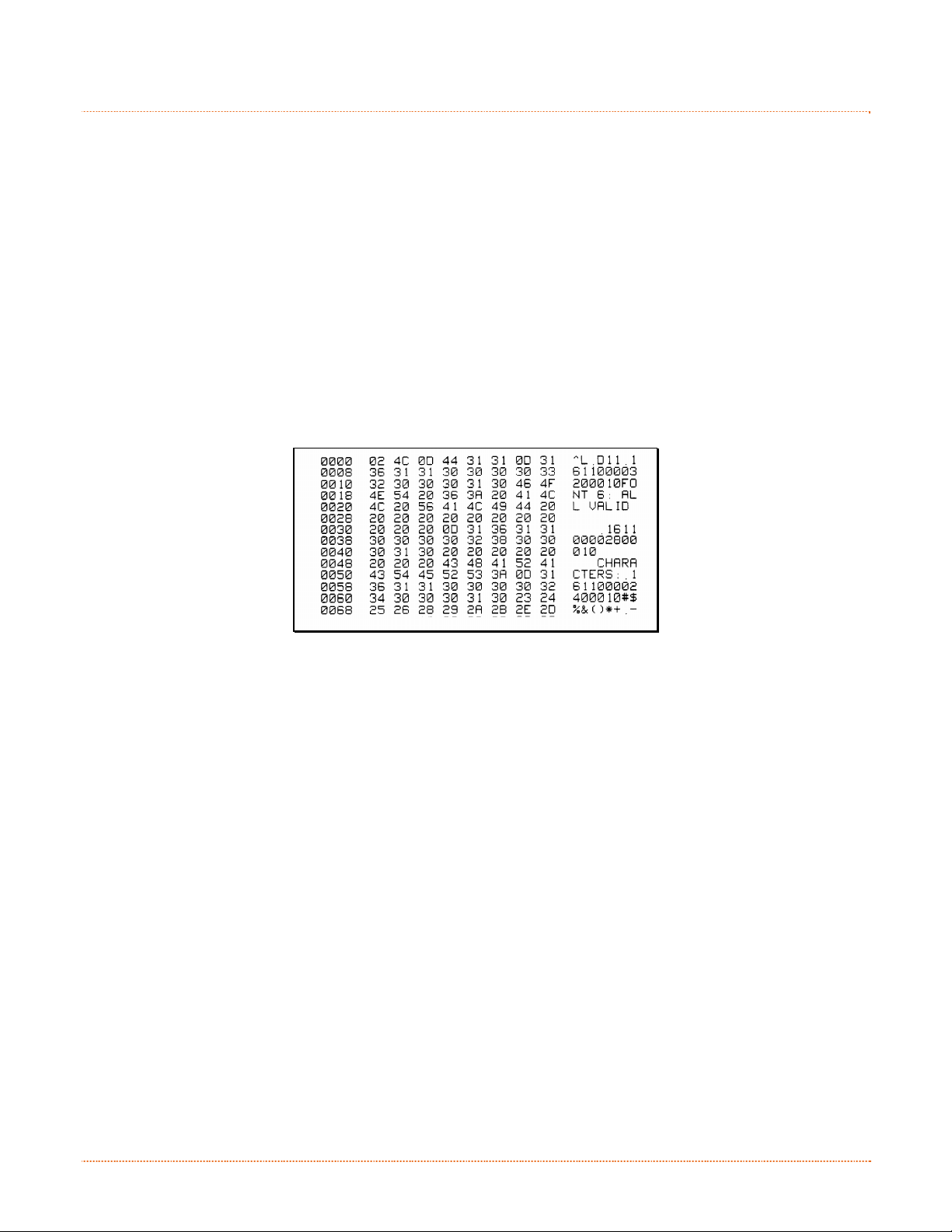
6
.
3
H
e
x
D
u
m
p
M
o
d
e
6
.
3
H
e
x
D
u
m
p
6
.
3
H
e
x
D
u
The Hex Dump Mode is a useful tool for diagnosing problems, including communication and DPL syntax
errors, allowing a comparison of input strings (sent by host) to output data (received by printer). To decode
this information, the Programmer’s Manual is an essential reference. This output can be used for debugging
the label format. In addition, by repeatedly sending a format, this mode can uncover handshaking problems
(if they exist). Handshaking problems are identified by sections of missing data in the character string.
To print the Hex Dump Label:
To begin, go to the Diagnostics menu and enable Hex Dump Mode; see Section 4.4. Exit the menu and save
the changes. Now, ‘HEX DUMP MODE’ will be indicated by the display and all data sent to the printer will now
be output in hexadecimal code, along with the printable ASCII equivalents, as shown below. To exit Hex Dump
Mode, re-enter the Diagnostics Menu and disable the Hex Dump Mode, exit the menu, then save the changes.
The figure below is a sample Hex Dump Label. After sending a label format to the printer, the hex code output
will be immediate. As a final note, many software programs use bit mapping to construct the label, making
diagnosis difficult. Contact Datamax-O’Neil Technical Support with any questions.
m
p
M
M
o
o
d
d
e
e
Chapter 6 – Troubleshooting 63
Page 70

64 Chapter 6 – Troubleshooting
Page 71

p
S
p
S
p
S
A
A
A
Mechanical
Width
e
c
e
c
e
Pro Models: 8.01 inches (20.4 cm)
Pro+ Models: 8.54 inches (21.7 cm)
i
i
f
f
i
i
c
c
a
a
t
t
i
i
i
t
a
c
i
f
i
c
o
o
o
n
n
n
s
s
s
Depth
Height
Weight
Operating Temperature
AC Input Voltage Power Supply:
Printing
Print Method Direct Thermal; Thermal Transfer (optional)
Print Speed
Resolution
Tear Bar Tear up
Pro Models: 11.10 inches (28.2 cm)
Pro+ Models: 14.17 inches (36.0 cm)
Pro Models: 7.36 inches (18.7 cm)
Pro+ Models: 9.45 inches (24.0 cm)
Pro Models: 5.25 pounds (2.4 kg)
Pro+ Models: 7.75 pounds (3.5 kg)
40 to 95 F (4 to 35 C)
105 VAC to 250 VAC / 50-60 Hz
203 DPI Models: 2 - 6 IPS (50.8 – 152.4mm/s)
300 DPI Models: 2 - 5 IPS (50.8 – 127mm/s)
203 DPI Models: 203 DPI (8 dots/mm)
300 DPI Models: 300 DPI (11.8 dots/mm)
DRAM Memory 16MB
FLASH Memory 64MB
Appendix A – Specifications 65
Page 72

Media / Ribbon
Media Types Roll-Fed, Die-Cut, Continuous, Fan-Fold
Max. Media Width 4.4 inches (110mm)
Min. Media Width 0.75 inches (19mm)
Max. Print Width
Print Length Range .236 – 99 in ches (6 - 2514mm)
Minimum Label Height
Media Thickness Range
Media Supply Roll Capacity
Ribbon Width Range
Ribbon Roll Capacity
203 DPI Models: 4.25 inches (108mm)
300 DPI Models: 4.12 inches (106mm)
Tear: 0.5 inches (12mm)
Peel: 1.0 inches (25mm)
Cut: 1.18 inches (30mm)
.0025 - .01 inches (.064 - .254mm); up to .005 inches (.127mm) with
optional Cutter
Pro Models: 5 inches (127mm) O.D. on a 1 inch (25.4mm) core
Pro+ Models: 7.2 inches (182.9mm) O.D. on 3 inch (76.2mm), 1.5
inch (38.1mm), or 1 inch (25.4mm) cores
½” Core Ribbons
Ribbon Core Width: 4.3 inches (110mm)
Ribbon Width: 1.0 - 4.3 inches (25 - 110mm); Centered on core
1” Core Ribbons (with Ribbon Core Adapters, see section 2.4.1.)
Ribbon Core Width: 1.0 - 4.3 inches (25 - 110mm); Centered on
Ribbon Core Adapters
Ribbon Width: 1.0 - 4.3 inches (25 - 110mm); Centered on core
0.5” (13mm) core with 361’ (110m) long ribbon or 1" (25mm) core
with 984' (300m) long ribbon
Communications
Interface Ports (standard)
Baud Speed 600 to 38,400 bits per second (BPS)
USB, RS-232 (DB-9), IEEE 1284 Type C compliant mini-Centronics
parallel, and 10/100 Wired LAN
Handshaking Xon/Xoff, CTS, DTR
Parity Even, Odd, or None
Stop Bits 1 or 2
Data Bits 7 or 8
Fonts
9 Bit Mapped Fonts rotated 0, 90, 180, and 270 degrees.
Embedded Bar Codes
32 embedded barcodes (see the Programmer’s Manual for a detailed listing).
66 Appendix A – Specifications
Page 73

Approved Media
To achieve optimum print quality and maximum printhead life, Datamax-O’Neil specifies the use of DatamaxO’Neil brand media and ribbons. These supplies are specially formulated for use in our printers; use of other
supplies may affect the print quality, performance, and life of the printer or its components. For a current list
of approved media and ribbons for use in direct thermal and thermal transfer applications, please contact a
Media Representative at (407) 523-5650.
G
I
H
F
J
D
E
A
B
A Label width
B Backing width 4.4 .75
C Gap between labels .25 .10
D Label length 24
E Total thickness .010
F Notch opening width -- .20
Distance from the center of the media to the
center of media sensor aperture. The distances
differ for “right of center” and “left of center”
G
and are dependant on whether transmissive or
reflective media is being used.
H Reflective mark width
I Distance between reflective marks 24
J Reflective mark length .25 .10
[1]
Units of measure are in inches.
[2]
The reflective (black) mark must be carbon based, placed on the backside of the
stock, and the reflectance shall be less than 10% at wavelengths of 950 and 640
nm.
[3]
The label length may vary up to 99 inches with printable area not exceeding the
maximum label length.
[4]
This distance is inclusive of the minimum gap between labels. Min length of 1.25
inches (31.8mm) with optional Cutter installed.
[5]
This distance is inclusive of the minimum reflective mark.
[6]
.007 inches (.117mm) w/Standard Cutter.
Description Max
203 DPI: 4.25
300 DPI: 4.12
Transmissive (Gap/Hole/Notch):
42mm to left and 34mm to right
[2]
4.4 .50
58mm to left and 38mm to right
[1]
[3]
.25
[6]
Reflective (Bar/Hole/Notch):
[3]
.25
C
[1]
Min
.75
[4]
.0025
[5]
Appendix A – Specifications 67
Page 74

68 Appendix A – Specifications
Page 75

d
n
a
s
s
e
l
e
r
k
k
k
C
a
C
C
i
r
i
r
i
r
i
r
i
r
i
r
d
a
S
r
d
a
r
d
button.
e
e
e
e
e
e
S
e
S
e
l
d
d
t
u
t
u
t
u
e
e
l
d
p
p
p
s
s
L
L
L
s
A
A
A
a
N
N
N
n
S
S
S
d
p
u
t
e
e
e
The information on this label will vary depending
on your configuration and firmware version.
t
t
u
u
p
p
d
n
a
s
W
W
W
B
B
B
B
.
1
N
B
.
1
B
.
1
Whether a wired or wireless connection is intended, it is recommend to establish a wired connection to the
printer first. This will allow access to the printers internal web pages to configure the settings necessary for a
typical wireless connection. If a wired connection is not or can not be achieved all connection parameters can
also be set using the NETira CT configuration utility, see section 3.5.
The printer makes IP requests at power-up, so before making a network connection to the printer consider
how your IP addressing needs to be assigned. The IP addressing of the printer can be configured in one of two
ways: Using a static IP Address or Using IP Discovery (DHCP, BootP, or RARP). At factory default settings
IP DISCOVERY is ENABLED (DHCP).
Once the previous steps have been successfully completed you may now use the IP Address to:
-or-
e
N
e
N
e
1. With Printer Off, connect the network cable then turn on Printer.
2. The printer will now search for a DHCP server. Allow up to 90 seconds for the printer to retrieve an IP
address.
3. At this point it is recommended to print a Network Report.
This Network Report is generated by the printer and lists
important default information such as the IP and MAC
Addresses as well as SSID for wireless equipped cards. To
print the ‘Network Report’:
Press the button to highlight the ‘TEST’ menu branch
and then press the
Using the button, scroll to Network Report, and then
press the
When prompted choose either “View” (to view the
information on the display) or “Print” (to print the
information).
4. Verify the printer has obtained a valid IP address for your
network. If a valid IP address was not obtained or you wish
to use a different static address this can be set via the
printer’s front panel.
Enter the printer’s menu and navigate to the Communications>Network/Bluetooth>Wired Ethernet
menu branch.
Set the “IP Discovery” menu item to “Use Static Addresses”.
Set the “IP Address” menu item to desired value, continue the same procedure with “Subnet
If your printer is equipped with wireless capabilities, browse to the printer’s internal web pages for
wireless/advanced configuration. See section B.2, Wireless Setup.
Install a printer driver, and start printing from your Windows applications. See section B.3,
Installing the Printer Driver.
W
W
W
t
w
o
r
t
w
o
r
t
w
o
r
button.
Mask” and “Default Gateway” menu items if necessary. Exit the printers menu. Cycle power to the
printer, upon start-up the printer will connect to the network using the new parameters you
provided.
Appendix B – WLAN & LAN Setup 69
Page 76

B
.
2
W
i
r
e
l
e
s
s
S
e
t
u
p
B
.
2
W
i
r
e
l
e
s
s
S
B
.
2
W
i
r
e
l
e
s
1. Open your web browser. Type in the IP Address assigned to the printer. The printers default IP
address is: 192.168.10.26.
The following page will appear:
The printer’s internal web pages are divided into
10 pages that are accessible via the navigation
bar on the left-hand side.
Most of the items on these pages mimic the
printer's internal menu. For more information on
the function of these settings see the
corresponding function in Chapter 4.
If a different IP Address has been assigned to the printer, make sure to enter the correct IP address.
s
e
S
e
t
u
p
t
u
p
You must provide a password to change any settings, the default password is “sysadm”.
If any address parameters were changed such as IP address, subnet or gateway, the printer might
not be viewable from the current host if they are no longer on the same subnet.
70 Appendix B – WLAN & LAN Setup
Page 77

B.2.1 Wireless Setup – Infrastructure
After a successful setup is made via a wired connection, the Wireless connection (if equipped) can now be
configured in infrastructure mode using a static or DHCP issued IP address.
1. Open your web browser. Type in the IP
Address of the printer. The Default IP is:
192.168.10.26.
If a different IP Address has been
assigned to the printer, make sure to
enter the correct IP address.
A page similar to the right will appear:
2. Click on the “Wireless Ethernet Settings” menu item on the left side of the screen. Locate and set the
following items:
In the “Acquire Address Method” section, select the “Use DHCP” radio button.
For static IP setup:
In the “Acquire Address Method” section, select the “Use Static Addresses” radio button.
In the “Static IP Addresses” section, enter valid static IP addresses for Printer IP Address,
Printer Subnet Mask, and Printer Gateway.
3. Scroll down the page to “Network Type”, select “infrastructure” from the drop down box.
4. In the SSID field type the name of the SSID of your access point.
5. Under the “WIFI Security and Authentication”, set any security/authentication settings necessary for
your network.
6. Scroll down to the bottom of the page, enter the password (default is “sysadm”) and click Apply.
7. Click on the “General Network Settings” menu item on the left side of the screen. Locate and set the
following items:
8. In the “Network Interface”, select the “Wireless Ethernet” radio button
9. Scroll down to the bottom of the page, enter the password (default is “sysadm”) and click Apply.
10. Click on the “Restore Defaults/Restart” menu item on the left side of the screen. Be sure that Restart
Printer is displayed in the “Action to Execute:” drop down box. Enter the password at the top of the
page (default is “sysadm”) and click Execute to restart the printer.
Appendix B – WLAN & LAN Setup 71
Page 78

The printer will now search for a server. Allow up to 90 seconds
for the printer to retrieve an IP address.
At this point it is recommended to print a Network Report. This
Network Report is generated by the printer and lists important
default information such as the IP and MAC Addresses as well as
SSID for wireless equipped cards. To print the ‘Network Report’:
Press the button to highlight the ‘TEST’ menu branch and
then press the
Using the button, scroll to Network Report, and then press
the
button.
When prompted choose either “View” (to view the information
on the display) or “Print” (to print the information).
Once the previous steps have been successfully completed you
may now use the IP Address to install a printer driver, and start
printing from your Windows applications. See section B.3,
Installing the Printer Driver.
button.
The information on this label will vary depending
on your configuration and firmware version.
B.2.1 Wireless Setup – Ad-Hoc
After a successful setup is made via a wired connection, the Wireless connection (if equipped) can now be
configured in ad-hoc mode using a static IP address. To configure the wireless card in Ad-hoc mode, you must
configure your host computer to match the IP settings of the printer. Refer to your operating system’s or your
wireless network card documentation for information on how to configure your computer.
1. Open your web browser. Type in the IP
Address of the printer. The Default IP is:
192.168.10.26.
If a different IP Address has been
assigned to the printer, make sure to
enter the correct IP address.
A page similar to the right will appear:
2. Click on the “Wireless Ethernet Settings” menu item on the left side of the screen. Locate and set the
following items:
In the “Acquire Address Method” section, select the “Use Static Addresses” radio button.
In the “Static IP Addresses” section, enter valid static IP addresses for Printer IP Address,
Printer Subnet Mask, and Printer Gateway.
3. Scroll down the page to “Network Type”, select “Ad-hoc” from the drop down box.
4. In the SSID field type the name of the SSID you wish to assign to the printer.
72 Appendix B – WLAN & LAN Setup
Page 79

5. Under the “WIFI Security and Authentication”, set any security/authentication settings necessary for
your network.
6. Scroll down to the bottom of the page, enter the password (default is “sysadm”) and click Apply.
7. Click on the “General Network Settings” menu item on the left side of the screen. Locate and set the
following items:
8. In the “Network Interface”, select the “Wireless Ethernet” radio button
9. Scroll down to the bottom of the page, enter the password (default is “sysadm”) and click Apply.
10. Click on the “Restore Defaults/Restart” menu item on the left side of the screen. Be sure that Restart
Printer is displayed in the “Action to Execute:” drop down box. Enter the password at the top of the
page (default is “sysadm”) and click Execute to restart the printer.
11. The printer will now search for a server. Allow up to 90 seconds for the printer to retrieve an IP
address.
12. From Windows, you may now “View
Wireless Networks”. From the list of
available wireless networks select the
printer that you wish to connect to and
then click on the Connect button.
If you do not see your printer listed be
sure you have the host computer
configured for Ad-hoc wireless networks.
This process will vary depending on your wireless device installed in your
host computer and your operating system version.
Once the previous steps have been successfully completed you may now use the IP Address assigned to the
printer to install a printer driver, and start printing from your Windows applications. See section B.3,
Installing the Printer Driver.
Appendix B – WLAN & LAN Setup 73
Page 80
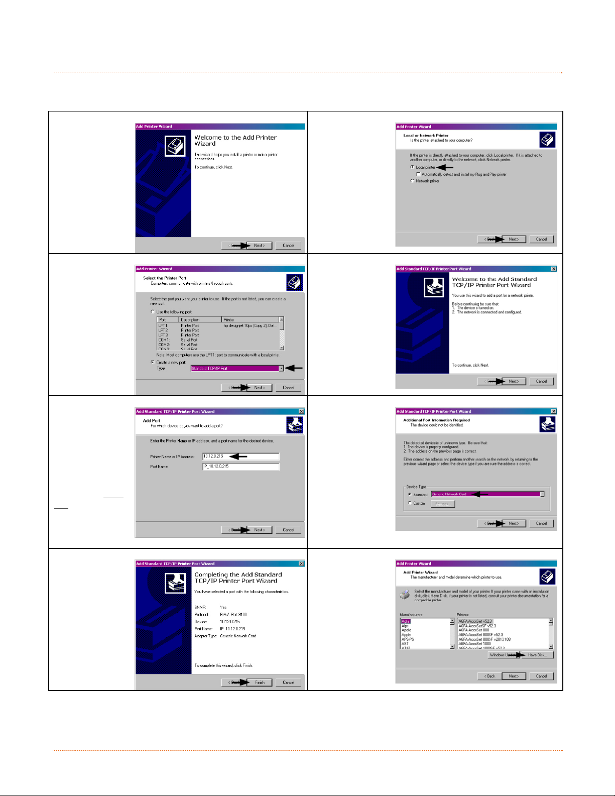
B
.
3
I
n
s
t
a
l
l
i
n
g
t
h
e
P
r
i
n
t
e
r
D
r
B
.
3
I
n
s
t
a
l
l
i
n
g
t
h
e
P
r
i
n
t
B
.
3
I
n
s
t
a
l
l
i
n
g
t
h
e
P
Install the Printer Driver as follows (screen shots below are samples taken using Windows 2000; other versions will
be similar):
1
Start the
Windows Add
Printer Wizard.
The following
screen should
appear, and
then click
Next>.
3
Select Create a
new port: and
then select
Standard TCP/IP
Port from the
drop down
menu. Click
Next>.
e
r
i
n
t
e
i
r
D
r
i
r
D
r
i
v
e
r
v
e
r
v
e
r
2
Make sure that
Local Printer is
selected and
then click
Next>.
4
Click Next>.
5
In the Printer
Name or IP
Address: field,
enter the IP
address of your
printer. The Port
Name field does
not need to be
changed. When
finished click
Next>.
7
Confirm your
settings and
then click Finish.
6
Make sure
Standard is
selected and
then click
Next>.
8
Click Have Disk
.
74 Appendix B – WLAN & LAN Setup
Page 81
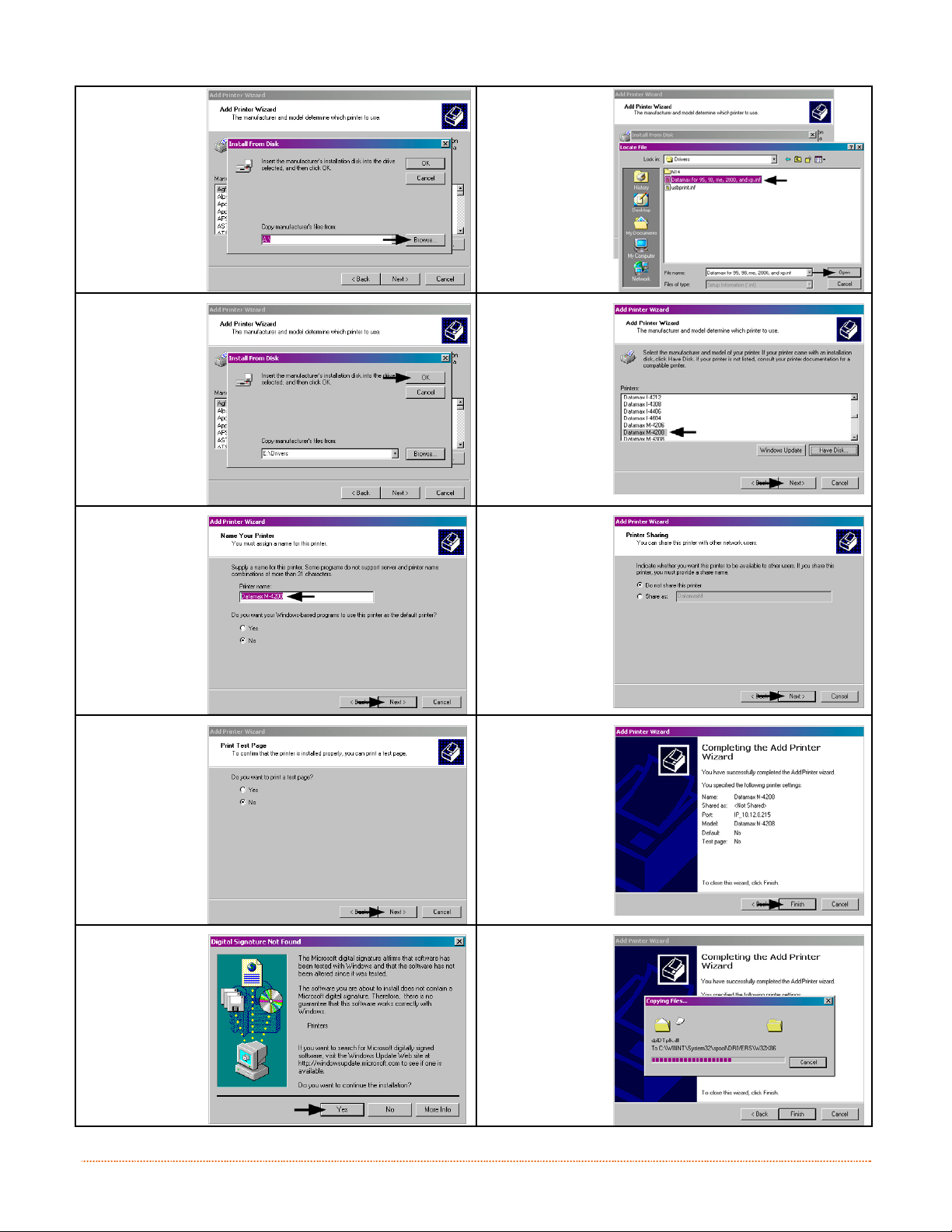
9
Insert the
Accessories CDROM and click
Browse.
11
Click OK.
10
Browse to the
\DRIVERS\
folder on the
CD-ROM.
Ensure the file
“DatamaxO’Neil.inf” is
selected then
click OK.
12
Choose your
printer from the
list and then
click Next>.
13
Assign a name
in the Printer
name field and
select whether
or not it is to be
your default
printer then
click Next>.
15
Select No then
Click Next>.
17
If prompted
with the Digital
Signature Not
Found window,
click Yes to
continue
installation.
14
Select whether
or not to share
this printer on
your network.
Then click
Next>.
16
Confirm your
settings and
then click
Finish.
18
Your computer
will now copy
the necessary
files from the
CD-ROM.
The driver and port installation is now complete. The printer can be selected through any Windows application.
Appendix B – WLAN & LAN Setup 75
Page 82

76 Appendix B – WLAN & LAN Setup
Page 83
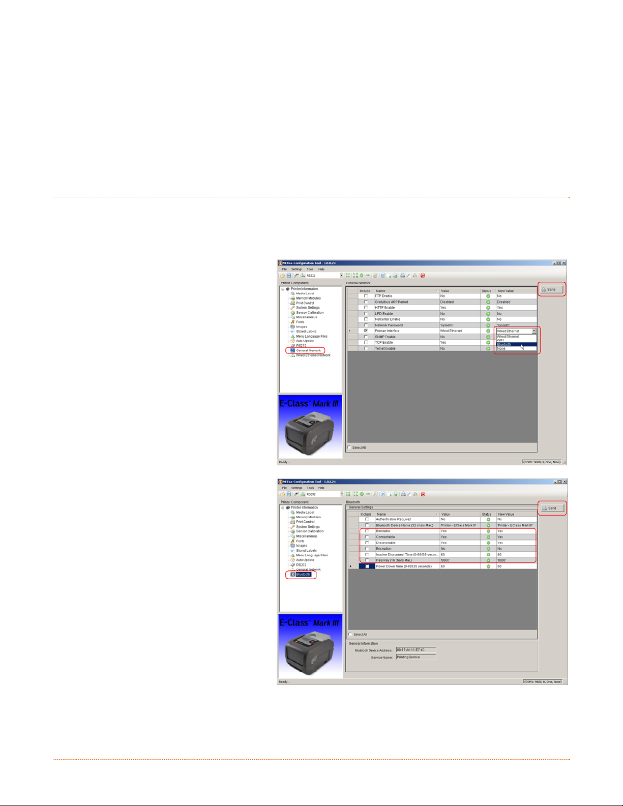
p
u
t
e
S
h
t
o
o
t
e
u
l
B
B
B
C
C
C
C
.
1
C
.
1
C
.
1
Bluetooth connection parameters can be set using the NETira CT configuration utility, via an established serial
or wired LAN connection.
Launch the NETira CT configuration utility, and query (connect) to the printer, (see section 3.3 for more
information on NETira CT).
1) Click on the General Network menu
branch under the Printer Component
section of the configuration utility.
2) In the Primary Interface setting; from the
drop down box, select Bluetooth. Send
the new setting to the printer using the
‘Send’ button. Allow 30 seconds for the
printer to reset.
3) Click the Bluetooth menu under the
Printer Component section of the
configuration utility.
4) To set up the printer for Bluetooth,
change (or confirm) the following
parameter settings:
Bondable: Yes
Connectable: Yes
Discoverable: Yes
PassKey: Default ‘0000’ (must match
5) Send the new settings to the printer using
the ‘Send’ button. Allow 30 seconds for
the printer to reset.
For connection to the printer please refer to the instructions included with your Bluetooth adapter or host
computer/handheld.
B
l
u
e
t
o
B
l
u
B
l
u
o
e
t
o
o
e
t
o
o
entry used on host computer)
u
l
u
l
t
h
S
e
t
h
t
h
t
S
e
t
S
e
t
e
e
u
p
u
p
u
p
t
t
o
o
o
o
t
t
h
h
S
S
e
e
t
t
u
u
p
p
Appendix C – Bluetooth Setup 77
Page 84

78 Appendix C – Bluetooth Setup
Page 85

e
g
a
u
g
n
a
L
u
n
n
n
g
g
g
t
e
e
e
h
t
h
t
h
e
e
e
n
n
M
M
M
e
e
e
u
u
n
u
n
u
n
u
L
L
a
n
L
L
a
a
n
n
g
g
g
a
u
a
u
a
u
a
n
g
e
g
e
g
e
g
u
a
g
e
e
g
a
u
g
n
a
L
M
M
M
D
D
D
D
.
1
C
h
a
n
g
i
D
.
1
C
h
D
.
1
Different languages and / or Datamax-O’Neil-provided translations can be downloaded to replace the standard
(English) menu of the printer by changing the spreadsheet that defines the system dictionary. To change the
language you will add a new language column (or modify the existing column) in the spreadsheet, click on the
“Generate DPL file(s)” radio button, and then send that file(s) to the printer.
Software requirements for modifying the menu language are as follows:
• Microsoft
• Img2dl.exe (provided at ftp://ftp.datamax-oneil.com/Printer%20Firmware/EFIGS-A.I.M.W.Class/) i s a
• Common.xls (also provided at the web site above) is the Menu Dictionary.
a
C
h
a
program used during the process to create the DPL file; and,
n
n
g
i
n
g
i
®
Excel must be purchased by user;
Create a Menu Language by following these steps:
A. Invoke Excel and open the Common.xls file. After the file opens, the following screen appears:
Place Img2dl.exe and Common.xls in the same directory.
Appendix D – Menu Language 79
Page 86
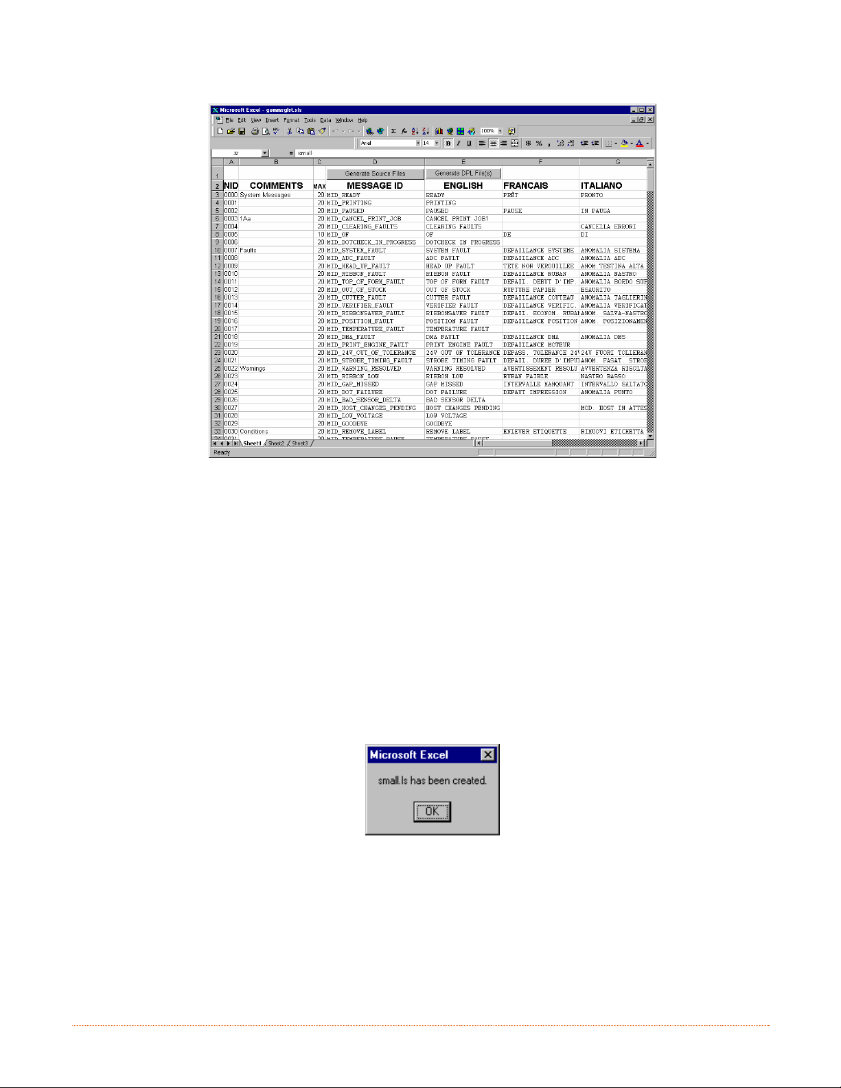
B. Click the “Enable Macro” box. The following screen appears:
C. Click on Column J and enter the new language, or modify an existing one. Some tips on this process:
• Message Size – When entering new messages, reference the “MAX” column: this is the maximum
number of characters allowed for this field. (Warnings are displayed when the number of
characters is exceeded, or when trying to modify the MAX value; however, if “cutting and pasting”
fields, this warning system may be defeated.)
• Two Line Messages – Some of the message are displayed as two lines. These are indicated in the
comment fields.
• Comments – This field can be modified with no effect.
D. After editing is complete, highlight all of the columns to be created by pressing the letter above the
column (more than one column can be selected).
E. Press the Generate DPL File(s) radio button. A file will be generated for each of the selected columns
and Excel will provide confirmation (for example, as shown below, small.ls).
80 Appendix D – Menu Language
Page 87
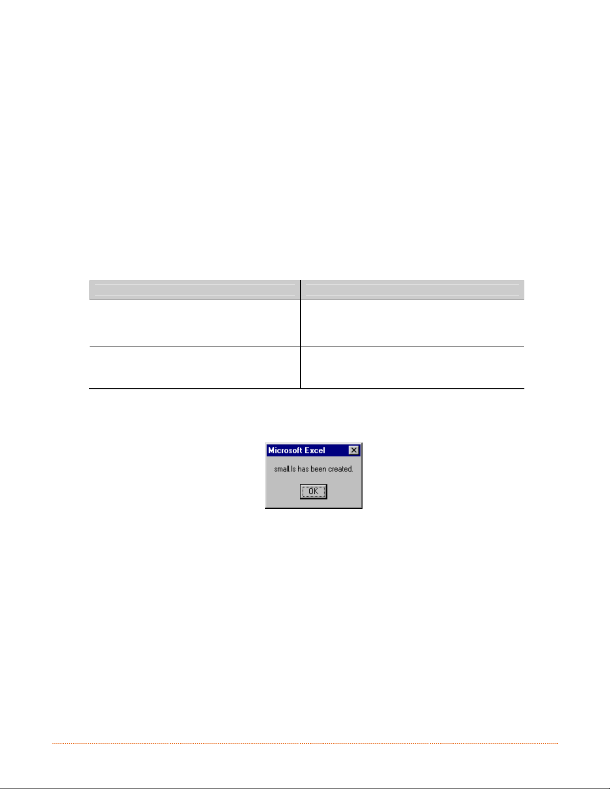
F. Download the generated files to the printer – one method is the DOS copy command:
copy small.ls lpt1: /b
G. Reset the printer by pressing and holding the CA NCEL Key for approximately four seconds.
H. After resetting, verify operation by printing a Configuration Label (see Section 4.4). New language
information will be printed under SYSTEM INFORMATION / OPTIONAL LANGUAGES. (Also, the new
language will appear on the display as a menu item in SYSTEM SETTINGS / MENU LANGUAGE. These
are the only methods to determine a successful download.)
Enable the new language. Enter the menu system and go to SYSTEM SETTINGS / MENU LANGUAGE
and select the new language. Next select the desired font for the language. Save the changes when
prompted. (A reset will occur as font validation is performed.)
An error has occurred if the printer displays the new language selection, but all messages remain in
English. In this case, re-check your process or contact Datamax-O’Neil Technical Support (be ready to
provide the Common.xls and DPL download files created). Other error messages are also possible:
Menu Language Error Message Description
Please select the entire column(s) or the
desired language(s), by clicking on the
column letter(s)
Message text may not exceed MAX = xx
designated characters for this MID
After pressing the Generate DPL File(s) radio
button, the languages to convert were not
correctly selected.
The entered message exceeds the number of
characters specified in column C. You may not
modify this number.
I. Repeat Steps A – H using the filename misc.xls to translate printer option items. This will output
small20.ls.
Appendix D – Menu Language 81
Page 88

D
.
2
A
d
v
a
n
c
e
d
F
i
l
e
H
a
n
d
l
i
n
g
I
n
f
o
D
.
2
A
d
v
a
n
c
e
d
F
i
l
e
H
a
n
d
l
i
n
g
D
.
2
A
d
v
a
n
c
e
d
F
i
l
e
H
a
n
d
l
•
The standard printer leaves the factory with EFIGS loaded into Module Y. At this point, Module Y is
LOCKED and will only accept additional language downloads.
• After downloading a language update, Module Y is left UNLOCKED until the printer is reset or power is
cycled. In this state, Module Y will accept font, image and label format downloads. The module will
also honor the Clear Module request. Therefore, following an update it is recommended that a reset be
performed to lock the module; otherwise, a software package may “Clear All Modules” thus destroying
the new menu language(s).
•
Module Y can be UNLOCKED by sending this DPL string: <STX>KpY0
• To restore the factory generated EFIGS image, download the file *832296.01A to the printer. This file
is located on the Datamax-O’Neil FTP site. The letter at the end of the file name (e.g., A) specifies the
revision. The latest revision will be available on the FTP site.
• Downloading the same language twice will automatically delete the first occurrence, but will not free
the memory space.
• Deletion of the selected language will reset the printer to English. The total number of languages that
the printer can now accept is limited to 10, but this number is dependent upon the size of each
language translation. The translation size will vary with the number of messages that are translated
for that particular language. Current complete language files are about 7,000 bytes each; but with
product growth, the total number of languages is expected to drop to five.
I
i
n
g
I
n
n
r
f
o
r
f
o
r
m
m
m
a
a
a
t
i
o
n
t
t
i
o
n
i
o
n
82 Appendix D – Menu Language
Page 89
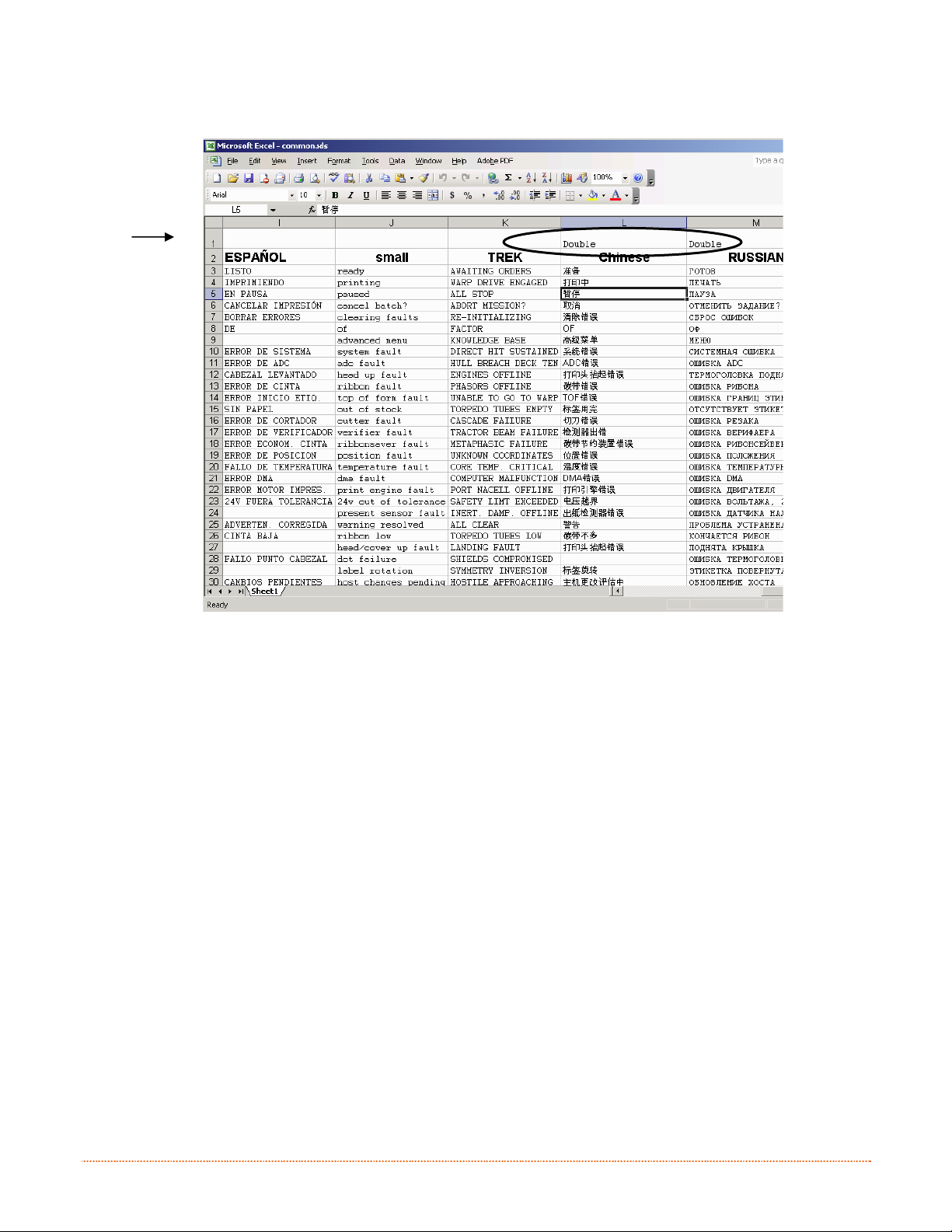
The screen shot below is an example of Unicode defined languages, Chinese & Russian. Note the
only additional information required is the “double” in row 1.
Appendix D – Menu Language 83
Page 90

 Loading...