

Page 1

Operator’s Manual
Basic and Advanced Models
Serial# 4xxxxxxx or greater
Page 2

Page 3

Copyright Information
CG Triumvirate is a trademark of Agfa Corporation.
CG Times based upon Times New Roman under license from the Monotype Corporation.
Windows is a registered trademark of the Microsoft Corporation.
All other brand and product names are trademarks, service marks, registered trademarks, or registered service
marks of their respective companies.
Limitation of Liability
In no event shall Datamax-O’Neil be liable to the purchaser for any indirect, special or consequential damages or
lost profits arising out of or relating to Datamax-O’Neil’s products, or the performance or a breach thereof, even
if Datamax-O’Neil has been advised of the possibility thereof. Datamax-O’Neil’s liability, if any, to the purchaser
or to the customer of the purchaser hereunder shall in no event exceed the total amounts paid to DatamaxO’Neil hereunder by the purchaser for a defective product.
In no event shall Datamax-O’Neil be liable to the purchaser for any damages resulting from or related to any
failure or delay of Datamax-O’Neil in the delivery or installation of the computer hardware, supplies or software
or in the performance of any services.
Some states do not permit the exclusion of incidental or consequential damages, and in those states the
foregoing limitations may not apply. The warranties here give you specific legal rights, and you may have other
legal rights which vary from state to state.
Firmware (Software) Agreement
The enclosed Firmware (Software) resident in the Printer is owned by Licensor or its suppliers and is licensed for
used only on a single printer in the user’s Trade or Business. The User agrees not to, and not to authorize
or permit any other person or party to, duplicate or copy the Firmware or the information contained
in the non-volatile or programmable memory. The firmware (Software) is protected by applicable copyright
laws and Licensor retains all rights not expressly granted. In no event will Licensor or its suppliers be liable for
any damages or loss, including direct, incidental, economic, special, or consequential damages, arising out of
the use or inability to use the Firmware (Software).
Information in this document is subject to change without notice and does not represent a commitment on the
part of Datamax-O’Neil Corporation. No part of this manual may be reproduced or transmitted in any form or by
any means, for any purpose other than the purchaser's personal use, without the expressed written permission
of Datamax-O’Neil Corporation.
Important Safety Instructions
This printer has been carefully designed to provide years of safe reliable performance. As with all types of
electrical equipment, however, there are a few basic precautions that should be taken to avoid personal
injury or damage to the device:
• Carefully read the installation and operating instructions provided with the printer.
• Read and follow all warning and instruction labels on the printer.
• Place the printer on a flat, stable surface.
• Do not insert anything into the ventilation slots or openings on the printer.
• Do not place the printer on or near a heat source.
• Do not use the printer near water. Never spill liquid into the printer.
• Be certain the power source is within the voltage rating and frequency listed for the printer. If you are unsure,
check with your dealer, an electrician, or local power company.
• Do not place the power cord where it can be stepped on. If the power cord becomes damaged or frayed,
replace it immediately.
• Only qualified, trained service technicians should attempt to repair the printer.
Cut-outs are not intended for wall-mount use.
Page 4

Agency Compliance and Approvals
C US
Listed
FCC: This device complies with FCC CFR 47 Part 15 Class A.
Note: This equipment has been tested and found to comply with the limits for a Class A digital
UL60950-1, Second Edition, 2007-03-27, Information Technology Equipment
CSA C22.2 No. 60950-1-07, Second Edition, 2007-03
The manufacturer declares under sole responsibility that this product conforms to the
following standards or other normative documents:
EMC: EN 55022 (2008) Class A
EN 50024 (1998)
IEC 60950-1 :2001, Second Edition
Safety: This product complies with the requirements of IEC 60950-1:2001, Second Edition
Customs Union – Russia, Kazakhstan, Belarus
GB4943-2001, GB9254-2008, GB17625.1-2012
E-4205A, E-4305A, E-4204B, E-4304B models:
The foregoing equipment has been registered under the Clause 3, Article 58-2 of Radio Waves Act
device, pursuant to Part 15 of the FCC Rules. These limits are designed to provide
reasonable protection against harmful interference when the equipment is operated in a
commercial environment. This equipment generates, uses, and can radiate radio
frequency energy, and if not installed and used in accordance with the instructions in
this manual, it may cause harmful interference to radio communications. Operation of
this equipment in a residential area is likely to cause harmful interference in which case
the user will be required to correct the interference at his own expense.
All rights reserved
Copyright © 2014, Datamax-O’Neil
Part Number: 88-2366-01, Revision B
Page 5

s
t
n
e
t
n
o
C
C
C
1
G
1
G
1
G
1.1 Introduction ........................................................................................................ 1
1.2 Unpacking the Printer ........................................................................................... 1
2
P
2
P
2
P
2.1 Introduction ........................................................................................................ 3
2.2 Connecting the Printer .......................................................................................... 3
n
o
n
o
e
t
t
i
n
e
e
r
r
r
g
t
t
i
n
g
t
t
i
n
g
i
n
t
e
r
i
n
t
e
r
i
n
t
e
r
2.2.1
2.2.2 Interface Connections ................................................................................. 4
Cable Requirements .............................................................................................. 4
e
t
e
t
S
t
a
r
t
e
S
t
S
t
S
e
S
e
S
e
Power Connections ..................................................................................... 3
d
a
r
t
e
d
a
r
t
e
t
u
p
.
t
u
p
.
t
u
p
.
n
n
.
.
.
d
.
.
.
.
.
.
.
.
.
.
.
t
t
.
.
.
.
.
.
.
.
.
.
.
.
.
.
.
.
.
.
.
.
.
.
.
.
.
.
.
.
.
.
.
.
.
.
.
.
.
.
.
.
s
s
.
.
.
.
.
.
.
.
.
.
.
.
.
.
.
.
.
.
.
.
.
.
.
.
.
.
.
.
.
.
.
.
.
.
.
.
.
.
.
.
.
.
.
.
.
.
.
.
.
.
.
.
.
.
.
.
.
.
.
.
.
.
.
.
.
.
.
.
.
.
.
.
.
.
.
.
.
.
.
.
.
.
.
.
.
.
.
.
.
.
.
.
.
.
.
.
.
.
.
.
.
.
.
.
.
.
.
.
.
.
.
.
.
.
.
.
.
.
.
.
.
.
.
.
.
.
.
.
.
.
.
.
.
.
.
.
.
.
.
.
.
.
.
.
.
.
.
.
.
.
.
.
.
.
.
.
.
.
.
.
.
.
.
.
.
.
.
.
.
.
.
.
.
.
.
.
.
.
.
.
.
.
.
.
.
.
.
.
.
.
.
.
.
.
.
.
.
.
.
.
.
.
.
.
.
.
.
.
.
.
.
.
.
.
.
.
.
.
.
.
.
.
.
.
.
.
.
.
.
.
.
.
.
.
.
.
.
.
.
.
.
.
.
.
.
.
.
.
.
.
.
.
.
.
.
.
.
.
.
.
.
.
.
.
.
.
.
.
.
.
.
.
.
.
.
.
.
.
.
.
.
.
.
.
.
.
.
.
.
.
.
.
.
.
.
.
.
.
.
.
.
.
.
.
.
.
.
.
.
.
.
.
.
.
.
.
.
.
.
.
.
.
.
.
.
.
.
.
.
.
.
.
.
.
.
.
.
.
.
.
.
.
.
.
.
.
.
.
.
.
.
.
.
.
.
.
.
.
.
.
.
.
.
.
.
.
.
.
.
.
.
.
.
.
.
.
.
.
.
.
.
.
.
.
.
.
.
.
.
.
.
.
.
.
.
.
.
.
.
.
.
.
.
.
.
.
.
.
.
.
.
.
.
.
.
.
.
.
.
.
.
.
.
.
.
.
.
.
.
.
.
.
.
.
.
.
1
.
.
.
.
.
.
.
.
1
.
.
.
.
.
.
1
.
.
.
.
.
.
3
.
.
.
.
.
.
3
.
.
.
.
.
.
3
2.3 Loading Media ...................................................................................................... 5
2.3.1 Loading Roll Media ..................................................................................... 5
2.3.2 Loading External or Fan-Fold Media .............................................................. 7
2.3.3 Loading Media with the Peel and Present Option .............................................. 9
2.3.4 Loading Media with the Cutter Option .......................................................... 10
2.4 Loading Ribbon .................................................................................................. 11
2.4.1 Using the Ribbon Core Adapters ................................................................. 14
3
P
r
i
n
t
e
r
O
p
e
r
a
t
i
o
n
.
.
.
.
.
.
.
.
.
.
.
.
.
.
.
.
.
.
.
.
.
.
.
.
.
.
.
.
.
.
.
.
.
.
.
.
.
.
.
.
.
.
.
.
.
.
.
.
.
.
.
.
.
.
.
.
.
.
.
.
.
.
.
.
.
.
.
.
.
.
.
.
.
.
.
3
P
r
i
n
t
e
r
O
p
e
r
a
t
i
o
n
.
.
.
.
.
.
.
.
.
.
.
.
.
.
.
.
.
.
.
.
.
.
.
.
.
.
.
.
.
.
.
.
.
.
.
.
.
.
.
.
.
.
.
.
.
.
.
.
.
.
.
.
.
.
.
.
.
.
.
.
.
.
.
.
.
.
.
3
P
r
i
n
t
e
r
O
p
e
r
a
t
i
o
n
.
.
.
.
.
.
.
.
.
.
.
.
.
.
.
.
.
.
.
.
.
.
.
.
.
.
.
.
.
.
.
.
.
.
.
.
.
.
.
.
.
.
.
.
.
.
.
.
.
.
.
.
.
.
.
.
.
.
.
.
3.1 Introduction ...................................................................................................... 15
3.2 LED Indicators ................................................................................................... 15
3.3 Multi-Function Button .......................................................................................... 16
3.4 Printer Configuration Tools .................................................................................. 17
3.5 Printer Configuration Utility (DMXConfig) ............................................................... 18
3.6 Windows Driver .................................................................................................. 21
3.7 Media Calibration ............................................................................................... 23
.
.
.
.
.
.
.
.
.
.
.
.
.
.
.
.
.
.
.
.
.
.
.
.
.
.
.
.
.
1
.
.
.
5
.
.
.
.
1
.
5
.
.
.
.
1
5
3.7.1 Quick Calibration ...................................................................................... 23
3.7.2 Media Calibration Wizard ........................................................................... 24
3.8 Internal Labels ................................................................................................... 26
3.8.1 Database Configuration Label ..................................................................... 26
i
Page 6

4
M
a
i
n
t
e
n
a
n
c
e
&
A
d
j
u
s
t
m
e
n
t
s
.
.
.
.
.
.
.
.
.
.
.
.
.
.
.
.
.
.
.
.
.
.
.
.
.
.
.
.
.
.
.
.
.
.
.
.
.
.
.
.
.
.
.
.
.
.
.
.
.
.
.
.
.
.
.
.
.
.
4
M
a
i
n
t
e
n
a
n
c
e
&
A
d
j
u
s
t
m
e
n
t
s
.
.
.
.
.
.
.
.
.
.
.
.
.
.
.
.
.
.
.
.
.
.
.
.
.
.
.
.
.
.
.
.
.
.
.
.
.
.
.
.
.
.
.
.
.
.
.
.
.
.
4
M
a
i
n
t
e
n
a
n
c
e
&
A
d
j
u
s
t
m
e
n
t
s
.
.
.
.
.
.
.
.
.
.
.
.
.
.
.
.
.
.
.
.
.
.
.
.
.
.
.
.
.
.
.
.
.
.
.
.
.
.
.
.
.
.
.
4.1 Introduction ...................................................................................................... 27
4.2 Cleaning the Printhead ........................................................................................ 28
4.3 Ribbon Tension Adjustment ................................................................................. 30
4.4 Adjustable Media Sensor ..................................................................................... 31
4.5 Printhead Replacement ....................................................................................... 32
4.6 Platen Roller Replacement ................................................................................... 34
4.7 Downloading Firmware and Fonts ......................................................................... 35
5
T
r
o
u
b
l
e
s
h
o
o
t
i
n
g
.
.
.
.
.
.
.
.
.
.
.
.
.
.
.
.
.
.
.
.
.
.
.
.
.
.
.
.
.
.
.
.
.
.
.
.
.
.
.
.
.
.
.
.
.
.
.
.
.
.
.
.
.
.
.
.
.
.
.
.
.
.
5
T
r
o
u
b
l
e
s
h
o
o
t
i
n
g
.
.
.
.
.
.
.
.
.
.
.
.
.
.
.
.
.
.
.
.
.
.
.
.
.
.
.
.
.
.
.
.
.
.
.
.
.
.
.
.
.
.
.
.
.
.
.
.
.
.
.
.
.
.
5
T
r
o
u
b
l
e
s
h
o
o
t
i
n
g
.
.
.
.
.
.
.
.
.
.
.
.
.
.
.
.
.
.
.
.
.
.
.
.
.
.
.
.
.
.
.
.
.
.
.
.
.
.
.
.
.
.
.
.
.
.
.
5.1 Introduction ...................................................................................................... 37
5.2 Troubleshooting Tips ........................................................................................... 37
A
S
p
e
c
i
f
i
c
a
t
i
o
n
s
.
.
.
.
.
.
.
.
.
.
.
.
.
.
.
.
.
.
.
.
.
.
.
.
.
.
.
.
.
.
.
.
.
.
.
.
.
.
.
.
.
.
.
.
.
.
.
.
.
.
A
A
S
p
e
c
i
f
i
c
a
t
i
o
n
s
.
.
.
.
.
.
.
.
.
.
.
.
.
.
.
.
.
.
.
.
.
.
.
.
.
.
.
.
.
.
.
.
.
.
.
.
.
.
.
.
.
.
S
p
e
c
i
f
i
c
a
t
i
o
n
s
.
.
.
.
.
.
.
.
.
.
.
.
.
.
.
.
.
.
.
.
.
.
.
.
.
.
.
.
.
.
.
.
.
.
.
.
.
.
.
.
.
.
.
.
.
.
.
.
.
.
.
.
.
.
.
.
.
.
.
.
.
.
.
.
.
.
.
.
.
.
.
.
.
.
.
.
.
.
.
.
.
.
.
.
.
.
.
.
.
.
.
.
.
.
.
.
.
.
.
.
.
.
.
.
.
.
.
.
.
.
.
.
.
.
.
.
.
.
.
.
.
.
.
.
.
.
.
.
.
.
.
.
.
.
.
.
.
.
.
.
.
.
.
.
.
.
.
.
.
.
.
.
.
.
.
.
.
.
.
.
.
.
.
.
.
.
.
.
.
.
.
.
.
.
.
.
.
.
.
.
.
.
.
.
.
.
.
.
.
.
.
.
.
.
.
.
.
.
.
.
.
.
.
.
.
.
.
.
.
.
.
.
.
.
.
.
.
.
.
.
.
.
.
.
.
.
.
.
.
.
.
.
.
.
.
.
.
.
.
.
.
.
.
.
.
.
.
.
.
.
2
.
.
.
.
.
.
.
.
7
.
.
.
.
2
.
.
.
7
.
.
.
.
2
7
.
.
.
.
3
7
.
.
.
.
3
7
.
.
.
.
3
7
.
.
.
.
3
9
.
.
.
.
.
3
9
.
.
.
3
9
B
E
t
h
e
r
n
e
t
S
e
t
u
p
.
.
.
.
.
.
.
.
.
.
.
.
.
.
.
.
.
.
.
.
.
.
.
.
.
.
.
.
.
.
.
.
.
.
.
.
.
.
.
.
.
.
.
.
.
.
.
.
.
.
.
.
.
.
.
.
.
.
.
.
.
.
.
.
.
.
.
.
.
.
.
.
.
.
.
.
.
.
.
B
E
t
h
e
r
n
e
t
S
e
t
u
p
.
.
.
.
.
.
.
.
.
.
.
.
.
.
.
.
.
.
.
.
.
.
.
.
.
.
.
.
.
.
.
.
.
.
.
.
.
.
.
.
.
.
.
.
.
.
.
.
.
.
.
.
.
.
.
.
.
.
.
.
.
.
.
.
.
.
.
.
.
.
.
B
E
t
h
e
r
n
e
t
S
e
t
u
p
.
.
.
.
.
.
.
.
.
.
.
.
.
.
.
.
.
.
.
.
.
.
.
.
.
.
.
.
.
.
.
.
.
.
.
.
.
.
.
.
.
.
.
.
.
.
.
.
.
.
.
.
.
.
.
.
.
.
.
.
.
.
.
.
B.1 Network Card Setup ........................................................................................... 43
B.1.1
B.2 Printer’s Internal Web Pages ................................................................................ 45
B.3 Installing the Printer Driver .................................................................................. 48
G
l
o
s
s
a
r
G
G
l
o
l
o
y
s
s
a
r
y
s
s
a
r
y
Wired Configuration - Static IP Address ....................................................... 43
.
.
.
.
.
.
.
.
.
.
.
.
.
.
.
.
.
.
.
.
.
.
.
.
.
.
.
.
.
.
.
.
.
.
.
.
.
.
.
.
.
.
.
.
.
.
.
.
.
.
.
.
.
.
.
.
.
.
.
.
.
.
.
.
.
.
.
.
.
.
.
.
.
.
.
.
.
.
.
.
.
.
.
.
.
.
.
.
.
.
.
.
.
.
.
.
.
.
.
.
.
.
.
.
.
.
.
.
.
.
.
.
.
.
.
.
.
.
.
.
.
.
.
.
.
.
.
.
.
.
.
.
.
.
.
.
.
.
.
.
.
.
.
.
.
.
.
.
.
.
.
.
.
.
.
.
.
.
.
.
.
.
.
.
.
.
.
.
.
.
.
.
.
.
.
.
.
.
.
.
.
.
.
.
.
.
.
.
.
.
.
.
.
.
.
.
.
.
.
.
.
.
.
.
.
.
.
.
.
.
.
.
.
.
.
.
.
.
.
.
.
.
.
.
.
.
.
.
.
.
.
.
.
.
.
.
.
.
.
.
.
.
.
.
.
.
.
.
.
.
.
.
.
.
.
.
.
.
.
.
.
.
.
.
.
.
.
.
.
.
.
.
.
.
.
.
.
.
.
.
.
.
.
.
.
.
.
.
.
.
.
.
.
.
.
.
.
.
.
.
.
.
.
.
.
.
.
.
.
.
.
4
3
.
.
.
.
.
.
.
.
.
.
.
.
.
.
.
.
4
3
.
.
.
4
3
.
.
5
1
.
.
.
5
1
.
.
.
5
1
ii
Page 7
d
e
t
r
a
t
S
g
n
i
t
t
e
G
G
G
1
1
1
1
.
1
1
.
1
1
.
1
The E-Class Mark III printer (hereafter referred to as “the printer”) is user-friendly thermal printing device
that blends quality and durability in an affordable package to meet all of your labeling needs. This manual
provides the information necessary to operate and maintain the printer.
To begin printing labels or tags, refer to the instructions included with your software labeling program. For
your convenience, a Windows printer driver can be found on the Accessories CD-ROM, or it can be
downloaded from our website at http://www.datamax-oneil.com. If you wish to write custom programs or
label formats, a copy of the DPL Programmer’s Manual is also included on the Accessories CD-ROM, or the
manual can be downloaded from our website.
1
.
2
1
.
2
1
.
2
I
n
t
r
o
d
u
c
t
k
k
u
k
u
i
c
t
i
c
t
i
i
n
g
i
n
g
i
n
g
I
n
t
r
o
n
n
d
t
r
o
d
p
a
c
p
a
c
p
a
c
I
n
U
n
U
U
e
e
o
n
o
n
o
t
t
t
n
h
h
h
t
t
e
P
e
P
e
P
t
t
r
r
r
n
i
n
i
i
n
t
e
r
i
n
i
n
t
e
r
t
e
r
g
g
S
S
t
t
a
a
r
r
t
t
e
e
d
d
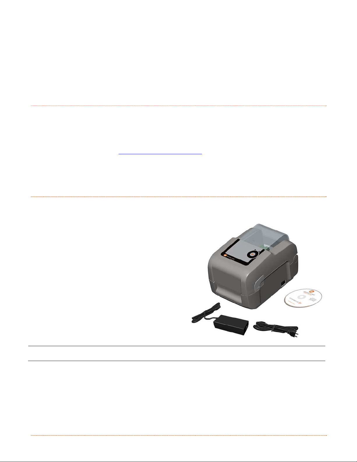
After removing the printer from the packaging material, check the contents of the box. In addition to the
printer, the following items should be present:
Power Supply
Accessories CD-ROM
Any special or additionally ordered items
Additional Requirements
The following items are necessary to generate labels:
Parallel, Serial, USB, or (if equipped for LAN
connectivity an Ethernet cable); see Section
2.2.2 for details.
Applicable media; see Appendix A for
details.
Contact customer support or your sales representative
for advice on the media and software that may best be
suited for your application.
It is a good idea to save all packaging material for future use.
312
Chapter 1 – Getting Started 1
Page 8

2 Chapter 1 – Getting Started
Page 9
p
u
t
e
S
r
e
t
n
i
r
P
r
P
P
2
2
2
2
.
1
2
.
1
2
.
1
This section explains how to connect your printer and load media (including ribbon, if equi pped for thermal
transfer operation).
2
.
2
2
.
2
2
.
2
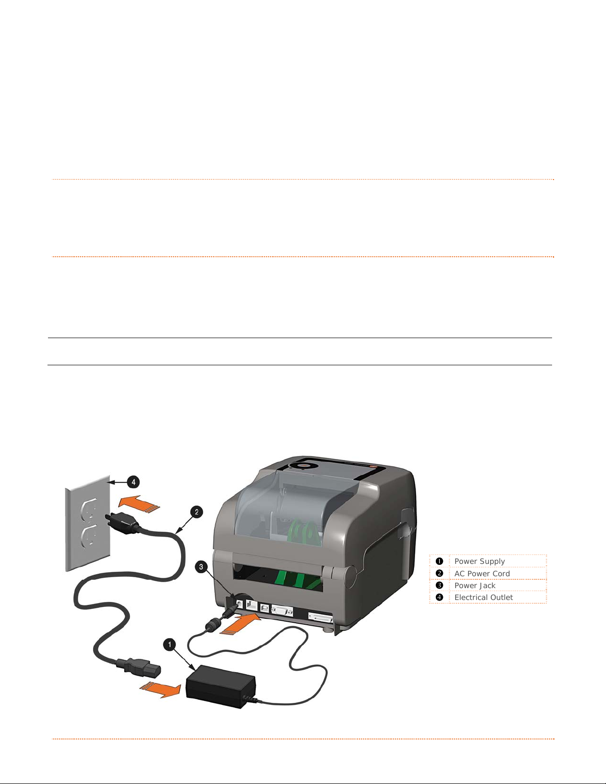
2.2.1 Power Connections
The printer is powered by an external auto-ranging power supply, which connects between the printer and an
electrical outlet. Ensure that the operating ranges of the power supply are compatible with your electrical
service, (see Appendix A for details) then connect power as follows:
I
I
I
C
C
C
n
t
n
t
n
t
o
n
o
o
n
n
r
o
d
u
c
t
c
c
c
u
u
i
c
t
i
c
t
i
t
i
n
t
i
n
t
i
n
r
o
d
r
o
d
n
e
n
e
n
e
r
o
o
o
g
g
g
n
n
n
t
i
i
t
t
n
n
h
h
h
e
e
e
e
t
e
t
P
r
i
n
P
t
r
i
n
t
r
i
n
t
P
e
e
e
r
r
r
r
r
S
S
e
e
t
t
u
u
p
p
Before connecting power to the printer, ensure that the Power Switch is in the OFF (O) position.
1) Connect the Power Supply to Power Jack of the printer.
2) Connect the AC Power Cord to the Power Supply.
3) Connect the AC Power Cord to an Electrical Outlet.
312
Power Supply
AC Power Cord
Power Jack
Electrical Outlet
Chapter 2 – Printer Setup 3
Page 10
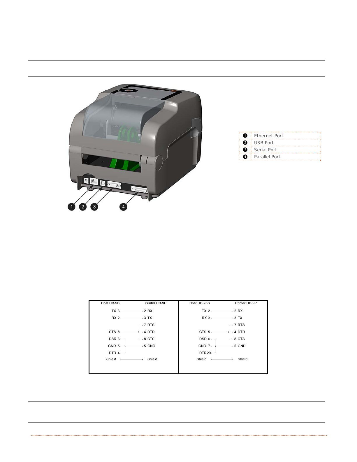
2.2.2 Interface Connections
The printer can be connected to the host system via the parallel, serial, Ethernet or USB ports.
Before connecting interface cables to the printer, ensure that the Power Switch is in the OFF (O) position.
312
Cable Requirements
Choose the correct cable when interfacing the printer to the host:
The Parallel Port (optional) supports parallel communications via a 36-pin male mini-Centronics
connector. Bi-directional communications (forward and reverse channels) is supported when an
IEEE 1284 compliant cable and supporting host software is used.
The Ethernet Port (optional) supports Wired LAN communications (see Appendix B for
information).
The Serial Port supports RS-232C communications via a DB-9 connector with specific pin-outs
(interface cable part numbers and pin-outs are given below; contact your reseller to order). Serial
port settings are menu-selectable and must match the host settings.
Ethernet Port
USB Port
Serial Port
Parallel Port
Part # 32-2483-01
Part # 32-2301-01
The USB Port supports high-speed serial communications and requires a standard USB interface
cable.
The printer automatically establishes communications with the first port through which valid data is
received. Afterward, a timeout period must be exceeded (or power must be cycled OFF and ON) to change
the established communications port.
4 Chapter 2 – Printer Setup
Page 11
2
.
3
L
o
a
d
i
n
g
M
e
d
i
a
2
.
3
2
.
3
L
o
a
d
i
n
g
M
L
o
a
d
i
n
If the printer is equipped with an Adjustable Media Sensor it may require adjustment to match your
media choice. If the printer is equipped with this type of sensor, proceed to Section 4.4.
g
M
e
e
d
d
i
a
i
a
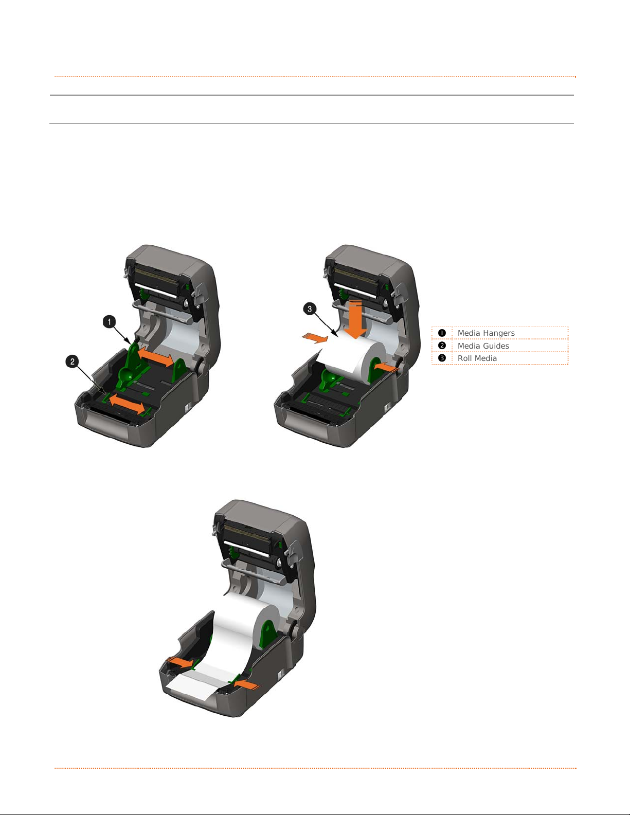
2.3.1 Loading Roll Media
Load media as follows:
1) Slide the Media Guides outward.
2) Slide the Media Hangers outward and insert the Roll Media as shown. Allow the Media Hangers to
retract and grasp the media roll.
312
Media Hangers
Media Guides
Roll Media
3) Pull out enough media to exit the front of the printer. Adjust the Media Guides so they are lightly
touching the edge of the media.
312
Chapter 2 – Printer Setup 5
Page 12
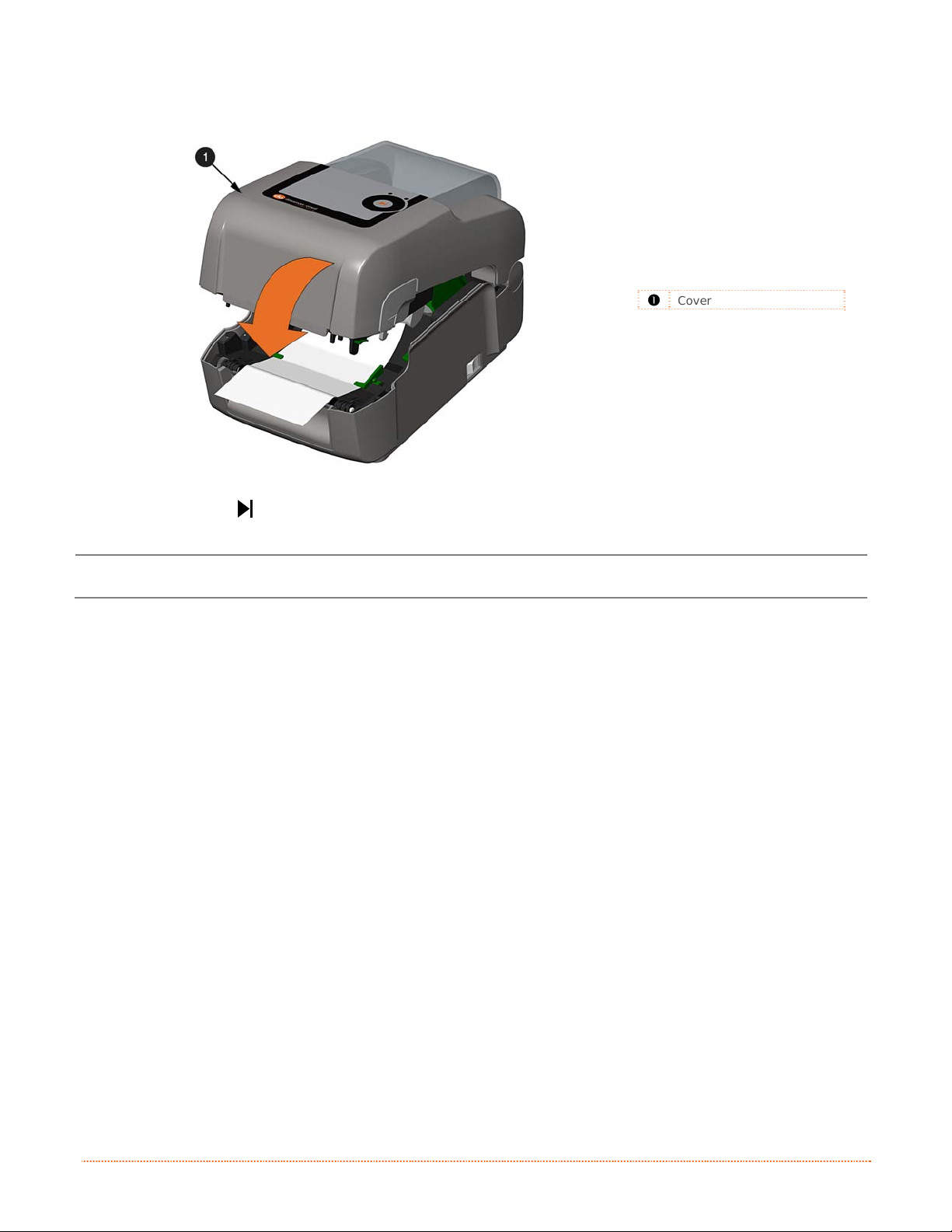
4) If using thermal transfer media (ribbon) proceed to Section 2.4 Loading Ribbon. Otherwise close
the printer’s Cover and press downward until latched.
312
Cover
5) Press the
button several times to advance the media (if the Fault Light is on, see Section 3.7.)
The printer is factory set to use gap media. If using another media type (for example, continuous
media), printer setup must be reconfigured; see Section 3.4
.
6 Chapter 2 – Printer Setup
Page 13
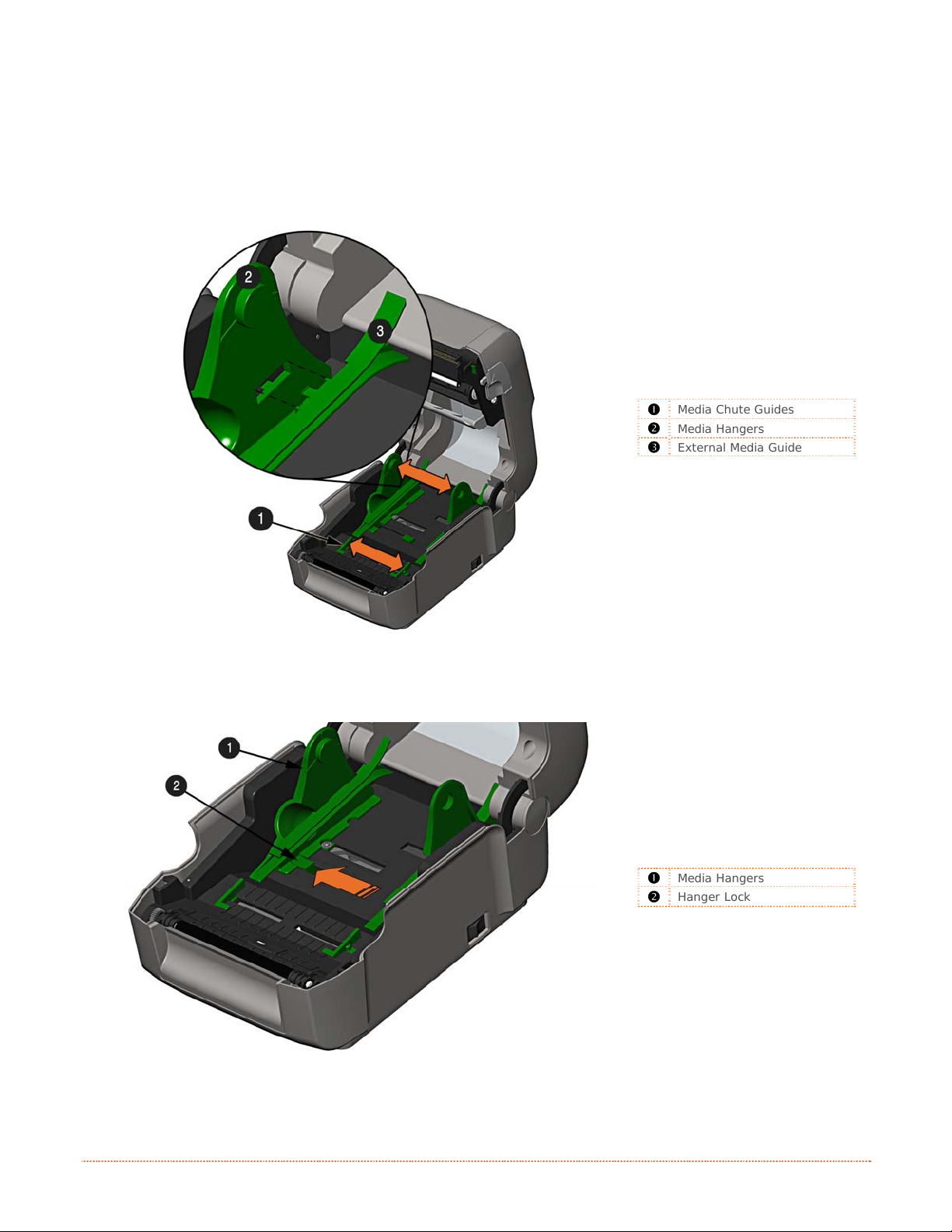
2.3.2 Loading External or Fan-Fold Media
Load media as follows:
1) Slide the Media Guides outward.
2) Slide the Media Hangers outward and install the two Media Chute Guides into the Media Hangers.
Media Chute Guides
Media Hangers
External Media Guide
3) Position the Media Hangers to match the width of the media being used. Slide the Hanger Lock
against the Media Hanger to hold this position.
Media Hangers
Hanger Lock
Chapter 2 – Printer Setup 7
Page 14
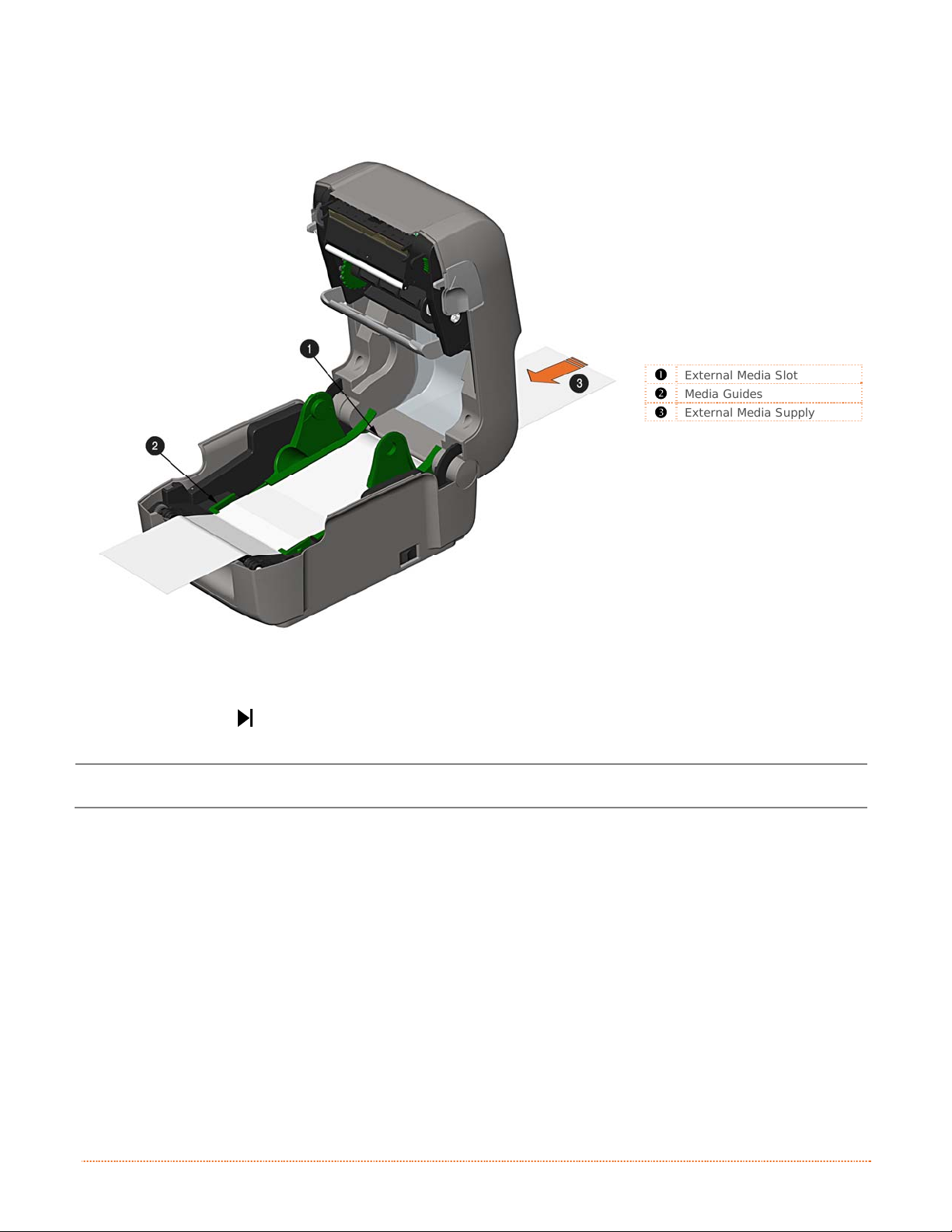
4) Route the media through the External Media Slot in the rear of the printer. Pull out enough media
to exit the front of the printer. Adjust the Media Guides so they are lightly touching the edge of
the media.
External Media Slot
Media Guides
External Media Supply
5) If using Thermal Transfer media (ribbon) proceed to Section 2.4 Loading Ribbon. Otherwise cl ose
the printer’s Cover and press downward until latched.
6) Press the button several times to advance the media (if the Fault Light is on, see Section 3.7.)
The printer is factory set to use gap media. If using another media type (for example, continuous
media), printer setup must be reconfigured; see Section 3.4
.
8 Chapter 2 – Printer Setup
Page 15
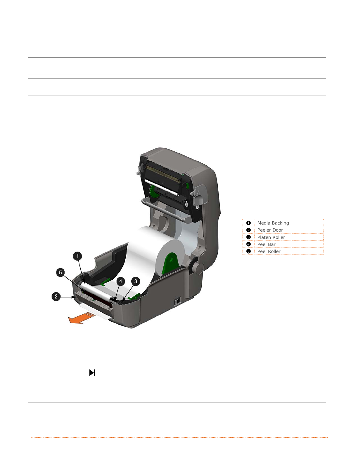
2.3.3 Loading Media with the Peel and Present Option
Load media for peeling (if the printer is equipped with the option) as follows:
When using the Peel Mechanism do not exceed a print speed of 4 IPS.
To utilize “Tear mode” with Peel and Present Option installed; move the Peeler Door to its open position.
1) Load media as described in Section 2.3, (steps 1-3).
2) Remove about 8 inches (200mm) of labels from the Media Backing.
3) Open the Peeler Door. Route the Media Backing over the Platen Roller and Peel Bar, and then
behind the Peel Roller and Peeler Door, as shown below.
312
Media Backing
Peeler Door
Platen Roller
Peel Bar
Peel Roller
4) Close the Peeler Door.
5) If using Thermal Transfer media (ribbon) proceed to Section 2.4 Loading Ribbon. Otherwise cl ose
the printer’s Cover and press downward until latched.
button several times to advance the media (if the Fault Light is on, see Section 3.7.)
.
6) Press the
7) The printer will now peel each label and present it to the operator for removal. The indicator light
will flash orange and the next label will not feed/print until the previous label is removed.
The printer is factory set to use gap media. If using another media type (for example, continuous
media), printer setup must be reconfigured; see Section 3.4
Chapter 2 – Printer Setup 9
Page 16
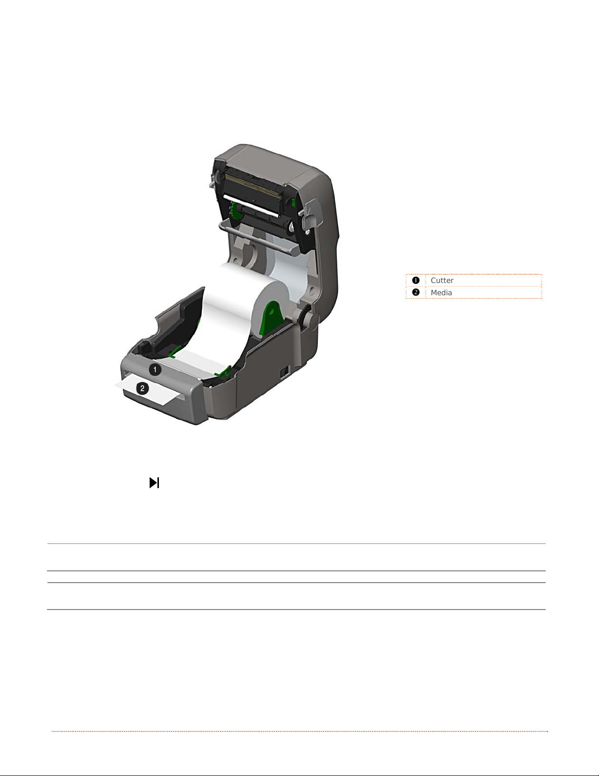
2.3.4 Loading Media with the Cutter Option
Load media for cutting (if the printer is equipped with the option) as follows:
1) Load media as described in Section 2.3, (steps 1-3).
2) Route the media through the opening in the Cutter.
312
Cutter
Media
3) If using Thermal Transfer media (ribbon) proceed to Section 2.4 Loading Ribbon. Otherwise cl ose
the printer’s Cover and press downward until latched.
4) Press the button several times to advance the media (if the Fault Light is on, see Section 3.7.).
The printer will now cut each label as it exits from the printer.
7) The printer will now peel each label and present it to the operator for removal.
If the printer is equipped with the Present Sensor Option, the indicator light will flash orange and the
next label will not feed/print until the previous label is removed.
The printer is factory set to use gap media. If using another media type (for example, continuous
media), printer setup must be reconfigured; see Section 3.4
.
10 Chapter 2 – Printer Setup
Page 17
2
.
4
L
o
a
d
i
n
g
R
i
b
b
o
n
2
.
4
L
o
a
d
i
n
g
R
i
b
2
.
4
L
o
a
d
i
n
g
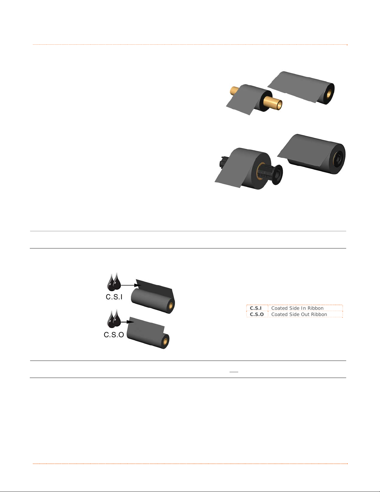
The printer is capable of using C.S.I (Coated Side In) and C.S.O (Coated Side Out) ri bbons in the following
configurations:
½” Core Ribbons
Ribbon Core Width: 4.3 inches (110mm)
Ribbon Width: 1.0 - 4.3 inches (25 - 110mm); Centered on core
1” Core Ribbons (with Ribbon Core Adapters, see section 2.4.1.)
Ribbon Core Width: 1.0 - 4.3 inches (25 - 110mm); Centered
on Ribbon Core Adapters
Ribbon Width: 1.0 - 4.3 inches (25 - 110mm); Centered on core
Load ribbon as follows:
If equipped with the thermal transfer option, the printer is factory set to use ribbon; see Section 3.4 to
change this setting if using direct thermal media.
1) Determine the type of ribbon (C.S.I or C.S.O) you are using.
b
R
i
b
b
o
o
n
n
312
C.S.I Coated Side In Ribbon
C.S.O Coated Side Out Ribbon
Ensure the inked side of the ribbon faces toward the label media, not the printhead.
Chapter 2 – Printer Setup 11
Page 18
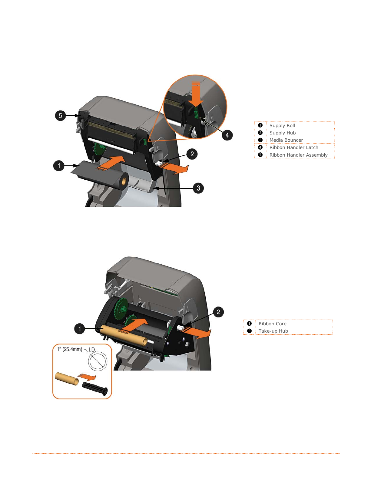
2) Push out the Supply Hub and load the Supply Roll into the printer as shown. Depending on the
size of the Supply Roll, the Media Bouncer may need to be pushed out of the way.
3) Once the Supply Roll is loaded, slide the Ribbon Handler Latch downward to unlatch the Ribbon
Handler Assembly.
312
Supply Roll
Supply Hub
Media Bouncer
Ribbon Handler Latch
Ribbon Handler Assembly
4) Push out the Take-up Hub and load an empty Ribbon Core into the printer as shown.
312
Ribbon Core
Take-up Hub
12 Chapter 2 – Printer Setup
Page 19

5) Route the ribbon from the supply roll to the Ribbon Core, as shown below.
6) If not already attached, affix the leader of the ribbon to the Ribbon Core using Tape. Rotate the
Take-up Hub Wheel several times to secure the ribbon.
312
Ribbon Core
Tape
Take-up Hub Wheel
7) Raise and latch the Ribbon Handler Assembly. Close the cover and press the
button several
times to advance the media (if the Fault Light is on, see Section 3.7.)
312
Ribbon Handler Assembly
Cover
Chapter 2 – Printer Setup 13
Page 20

2.4.1 Using the Ribbon Core Adapters
When using ribbons with a 1” (25.4mm) I.D. core, a Core Adapter must be used.
1) Slide the Ribbon Roll (with the leader positioned as shown above) onto a Core Adapter. Slide an
empty Ribbon Core onto the remaining Core Adapter.
312
Core Adapter
Ribbon Roll
Ribbon Core
2) If using a narrow ribbon, position the Ribbon Roll so that it is centered on the Core Adapter. The
Core Adapters are marked in both inches and centimeters to aid in proper positioning.
Core Adapter
Ribbon Roll
312
14 Chapter 2 – Printer Setup
Page 21

n
o
i
t
a
r
e
O
O
p
p
p
e
e
r
r
a
a
t
i
t
Green/Orange Status LED
Red Error LED
Multi-function Button
o
n
n
o
i
P
r
P
P
3
3
3
3
.
1
3
.
1
3
.
1
The Front Panel consists of two indicator lights and one multi-function button, as detailed in the following
sections.
I
n
t
r
o
d
u
c
t
I
n
t
r
o
I
n
d
t
r
o
d
u
u
c
c
i
t
i
t
i
r
o
o
o
n
n
n
i
i
n
n
t
t
312
e
e
r
r
O
r
e
t
n
i
r
s
LED 1 LED 2
Paused or Present
Sensor is blocked.
No power
TOF sensing error. Next TOF not Found.
Red
No Error
3
.
2
L
E
D
I
n
d
i
c
a
t
o
r
3
.
2
L
E
D
I
n
d
i
c
3
.
2
L
E
D
I
n
Two LED indicator lights provide a quick visual reference of printer operations and conditions, as defined
below:
Color Green Orange
Solid
Flashing
Off
a
d
i
c
a
Ready to print
Processing/busy Paused/busy Out of stock\labels or printer jam..
s
t
o
r
s
t
o
r
Chapter 3 – Printer Operation 15
Page 22

3
.
3
M
u
l
t
i
-
F
u
n
c
t
i
o
n
B
u
t
t
o
n
3
.
3
M
u
l
t
i
-
F
u
n
c
t
i
o
n
B
u
3
.
3
M
u
l
t
i
-
F
u
n
c
t
i
o
n
The multi-function button performs different functions depending upon the mode of the printer:
Button Action
Momentary Press
Press and hold for 5
seconds (release when
LED blinks orange)
Press and hold for 10
seconds (release when
LED blinks green)
Press and hold for 15
seconds (release when
LED blinks red)
Press and hold for 20
*Dealer Settings can b e d efin ed and mod ified us ing t he NET ira CT c onfig ur atio n ut ility, se e s ec tio n 3.5
seconds
LED 1 – Green
Ready/Idle
Printer feeds media to
the next label.
Prints Network Report
Performs the Quick
Media Calibration
Resets the printer’s
parameters to the
stored Dealer Settings*
t
B
u
t
Label
Performs a ‘warm reset’. Does not affect any stored printer settings.
t
o
n
t
o
n
LED 1 – Green
Printing
Pauses Printer Resumes printing Clears Fault
Cancel Batch Cancel Batch
LED 1 – Orange
Paused
Performs the Quick
Media Calibration
Resets the printer’s
parameters to the
stored Dealer Settings*
LED 2 – Red
Faulted
Performs the Quick
Media Calibration
Resets the printer’s
parameters to the
stored Dealer Settings*
16 Chapter 3 – Printer Operation
Page 23

3
.
4
P
r
i
n
t
e
r
C
o
n
f
i
g
u
r
a
t
i
o
n
T
o
o
l
s
3
.
4
P
r
i
n
t
e
r
C
o
n
f
i
g
u
r
a
t
i
o
n
T
3
.
4
P
r
i
n
t
e
r
C
o
n
f
i
g
u
r
a
t
i
o
The printer contains many user adjustable parameters. These parameters are configurable using a few
methods. The table below lists the most popular ways of configuring the printer and the advantages of each.
Choose the method that best addresses your application.
Method Description Pros Cons For More Info
NETira CT (located on the
Accessories CD-ROM) is a
Windows based configuration
NETira CT
Program*
Internal Web
Pages*
utility that allows the user to
make changes to the existing
printer setup via a direct
connection to the host computer’s
serial, USB, parallel or LAN
connection.
Internal web pages are simple
HTML pages that can be accessed
with any web browser via the
optional Ethernet port.
n
o
T
o
o
l
s
o
l
s
Easy to use, gives the
user the most control
of the printer.
Easy to use. Printer
can be configured from
any host connected to
the network regardless
of physical location or
host operating system.
No additional software
required.
Software must be
installed on a Windows
based host computer.
Printer must be
equipped with an
Ethernet option.
Depending on the
complexity of the
network, initial
connection may not be
possible until network
parameters are set via
another method.
See
Section 3.5
See
Appendix B.2
Windows
Driver
DPL
Programming
Commands
* Recommended methods
The Windows printer driver
(located on the Accessories CDROM).
DPL Programming Language
commands can be built into
custom label formats or sent
individually to the printer.
Many applications
require use of driver
for printing from 3
party applications. This
can be an all in one
solution for some users
that do not require
advanced setups.
DPL commands can be
built directly into label
formats which can
configure the printer
on the fly.
rd
Requires installation of
a driver on a Windows
based host.
Only basics parameters
can be configured.
DPL programming
knowledge needed.
See
Section 3.6
See the
DPL
Programmer’s
Manual
Chapter 3 – Printer Operation 17
Page 24

3
.
5
P
r
i
n
t
e
r
C
o
n
f
i
g
u
r
a
t
i
o
n
U
t
3
.
5
P
r
i
n
t
e
r
C
o
n
f
i
g
u
r
a
t
i
o
3
.
5
P
r
i
n
t
e
r
C
o
n
f
i
g
u
r
NETira CT (located on the Accessories CD-ROM) is a Windows-based configuration utility that allows the user
to make changes to the existing printer setup via a direct connection to the host computer’s serial, USB,
Ethernet, or parallel ports.
NETira Features:
USB and Parallel Port Connection Requirements
Using Netira CT with an USB or parallel port connection requires a Windows driver to be installed and the
driver to be set to “Print directly to the printer”. Other connections (e.g. serial and LAN) do not require the
Windows driver or this setting. Install the Windows driver as described in section 3.6. Then follow the steps
below to set the driver setting:
1) Open the list of installed printers on your PC.
2) Right click on the printer and select Properties
3) In the Driver Properties window, click on the
4) Click the “Print directly to the printer” radio
USB and parallel port connections will now be
available for use with Netira CT.
Allows Real-Time Control/Query of Printer Configuration
Define and Save Optimal Configurations for Applications
Saved Configurations can be Shared with other Printers and Sent via Email
Download Files, Formats and Fonts
Query Memory Modules
Be sure to use the NETira utility located on the Accessories CD-ROM that is included with your
printer. Older versions might not operate correctly with some printers. For the latest version please
visit our web site at http://www.datamax-oneil.com
Be sure your printer’s firmware version is 9.04 or greater. Firmware is available from our website,
for the latest version please visit our web site at http://www.datamax-oneil.com
Windows XP
Open Printer and Faxes by clicking the Start
button, and then Settings, and then click on Printer
and Faxes.
Windows 7
Open Devices and Printers by clicking the Start
button, and then click on Devices and Printers.
from the drop down menu.
Advanced tab.
button. Then click OK.
a
n
t
i
o
n
i
U
t
i
U
t
i
(
N
E
T
i
r
a
C
T
)
l
i
t
y
(
N
E
T
i
r
a
l
i
t
y
(
N
l
i
t
y
E
T
i
r
a
C
C
T
T
)
)
18 Chapter 3 – Printer Operation
Page 25

NETira CT Usage
1) Once installed launch the NETira CT configuration utility:
2) Be sure the printer is ‘ON’. Connect the host to the printer (see Section 2.2.2 Interface Connections).
For Serial Connections:
a) Query the printer by using the ‘Auto Detect’ button.
This will connect to the printer and retrieve the
setting currently stored in the printer.
For USB and Parallel Connections:
Close the ‘Open a configuration file…’ dialogue box.
a) In the toolbar, from the drop down menu box,
select the appropriate port Then click on the Query
Printer Icon
For Ethernet Connections:
Close the ‘Open a configuration file…’ dialogue box.
a) In the toolbar, Click on the ‘ TCP/IP Configuration’
Icon
.
b) In the ‘TCP/IP Configuration’ dialogue box enter the
IP address of the printer, Port: 9100 and click ‘OK’.
(The IP address is displayed on the printer’s
Network Report and Configuration Labels).
c) In the toolbar, from the drop down menu box, select
“TCP_IP”. Then click on the Query Printer Icon
.
.
Chapter 3 – Printer Operation 19
Page 26

3) At this point you may browse the Printer Component
categories and make any changes necessary to the
printer configuration.
4) Once complete, send the new settings to the printer using
the ‘Send’ button.
Note: When sending the changes to the printer, only the
changes displayed on the current page will be
sent. You must click the ‘Send’ button for each
page that has been modified.
20 Chapter 3 – Printer Operation
Page 27

3
.
6
W
i
n
d
o
w
s
D
r
i
v
e
r
3
.
6
W
i
n
d
o
w
s
D
r
3
.
6
W
i
n
d
o
w
s
The Windows driver is located on the Accessories CD-ROM included with your printer. For the latest version
please visit our web site at http://www.datamax-oneil.com
Be sure your printer’s firmware version is 9.04 or greater. Firmware is available from our website,
Installing the Windows Driver:
1) Place the Accessories CD-ROM included with your
2) Once the CD-ROM starts select your printer model then
3) When prompted, select your pri nter from the list, (i.e.
for the latest version please visit our web site at http://www.datamax-oneil.com
Be sure your printer’s USB Mode is set to “Printer”. This mode can be viewed/changed via the
printer’s front panel menu under: Communications> USB Port> USB Device Class.
printer into your computers CD-ROM drive.
“Install Driver” from the menu and follow the
instructions on the screen to install.
Datamax-O’Neil E-4xxx Mark III). Continue to follow
the on-screen instructions to install the driver.
i
D
r
v
e
r
i
v
e
r
Chapter 3 – Printer Operation 21
Page 28

Important Notes:
The Windows driver functions the same as any other Windows printer. While built-in help files provide
information on all settings, there are some important setting parameters that should be observed for trouble
free printing:
Page Setup Tab: Stock
It is important that the Stock setting matches the
size of the label you are using. If you cannot find a
match for your label click New and enter the
dimensions of your label.
Options Tab: Print Speed & Printhead Temperature
These two settings will have the greatest effect on
print quality. Some label stocks will require more
heat and slower print speeds to generate a quality
image.
The Windows application software used to create the label format will likely have a "Page Setup" screen. This
will also need to match the size of the label you are using.
22 Chapter 3 – Printer Operation
Page 29

3
.
7
M
e
d
i
a
C
a
l
i
b
r
a
t
i
o
n
3
.
7
M
e
d
i
a
C
a
l
i
b
r
3
.
7
M
e
d
i
a
C
a
The printer is factory calibrated for operation with most media types (both gap and black mark). Try your
media without performing any calibration adjustments first; this will determine if the factory settings are
compatible. Only perform the calibration adjustments if you are experiencing media registration issues.
The Quick Media Calibration should be performed first, if it fails to detect your label media proceed to the
Manual Media Calibration procedure, see section 3.7.2.
a
l
i
b
r
a
t
i
o
n
t
i
o
n
3.7.1 Quick Calibration
The Quick Media Calibration can be performed using the NETira CT configuration utility, (see section 3.5 for
more information on NETira CT).
Launch the NETira CT configuration utility, and query (connect) to the printer.
1) Click on the ‘Sensor Calibration’
printer component.
2) Install your media in the
printer and click the ‘Quick
Media’ button.
3) The printer will feed media
while the sensor is being
calibrated. At the end of the
process the following message
will be shown, indicating a
successful calibration. Values
displayed in the “New Value”
column may change after a
calibration.
If the calibration is not
successful, repeat the
procedure. If the Quick Media
calibration continues to fail,
proceed to section 3.7.2
Manual Media Calibration
Chapter 3 – Printer Operation 23
Page 30

3.7.2 Manual Media Calibration
The Manual Media Calibration is intended for use when Quick Media Calibration printer has failed to detect the
start of each label. This procedure performs a complete recalibration of the sensors and will optimize the
printer to your media. In some instances you may need to perform a Quick Media Calibration after the Manual
Media Calibration to further optimize the printer’s sensor.
Sensor calibration is needed to set either the black mark or the gap value of the media sensor on the printer.
The Manual Media Calibration can be performed using the NETira CT configuration utility, (see section 3.5 for
more information on NETira CT).
Launch the NETira CT configuration utility, and query (connect) to the printer.
Procedure for Gap Type Media:
1) Click on the ‘Sensor Calibration’
printer component.
2) Click the ‘Manual Media’ button
to start the manual calibration
process.
Follow the instructions on the
following screen.
3) Select the Interlabel/Gap radio
button then click ‘OK’.
4) Load Stock: Place the face of
media over the sensor, close
the door then click ‘OK’.
24 Chapter 3 – Printer Operation
Page 31

5) Load Special Backing Media for
Gap: Peel the label(s) off
backing and place backing over
the sensor and close the door
then click ‘OK’.
6) Remove Stock: Remove all
media from printer, close the
door then click ‘OK’.
7) NETira CT will display a
message indicating the process
has finished.
In case of any error, a FAILED
CALIBRATION message will be
displayed. Repeat the process.
Chapter 3 – Printer Operation 25
Page 32

3
.
8
I
n
t
e
r
n
a
l
L
a
b
e
l
s
3
.
8
I
n
t
e
r
n
a
l
L
a
3
.
8
I
n
t
e
r
n
a
The following section details the resident information and test labels.
3.8.1 Database Configuration Label
The Database Configuration Label provides information
including the printer firmware version, memory allocations,
enabled options, and label-counter data.
Print a Database Configuration Label as follows:
1) Load with media (4 inch wide) and ribbon (if printing
with thermal transfer media).
2) Turn the printer on.
3) When the left LED is on (solid red), press and hold the
button until the left LED turns (solid green) and then
release. The Database Configuration Label will then
print.
b
l
L
a
b
e
e
l
s
l
s
(Printed label may not match the label shown above.)
26 Chapter 3 – Printer Operation
Page 33

&
&
e
c
n
a
n
e
t
n
i
A
A
A
c
t
c
t
c
t
a
i
a
i
a
d
d
d
i
o
n
i
o
n
i
o
n
Turn OFF the printer before cleaning the printhead.
Use solvent* applied with a cotton swab to clean
the printhead from end to end.
Turn OFF the printer. Rotate the platen roller and
clean it thoroughly with solvent* applied with a
cotton swab.
Rotate the peel-off roller and clean it thoroughly
with solvent* applied with a cotton swab.
n
n
u
j
u
j
u
j
t
t
e
e
s
s
s
n
n
t
t
t
m
m
m
a
a
n
n
e
e
e
n
c
c
n
n
&
e
e
s
t
s
t
s
t
After every roll of media.
After every roll of media.
After every roll of media.
M
M
M
4
4
4
4
.
1
4
.
1
4
.
1
This section details the cleaning, adjusting, and troubleshooting tips for the printer. The following table
outlines the recommended maintenance schedule for the various printer parts.
I
n
I
n
I
n
Printhead
Platen Roller
Peel-Off Roller
t
r
o
d
t
t
u
r
o
d
u
r
o
d
u
Area Method Interval
Media Path Solvent* After every roll of media.
Peel/Tear Bar Solvent* As needed
Media Sensor Blown air or brush Monthly
Exterior Mild detergent or desktop cleaner. As needed
Interior Brush or vacuum cleaner As needed.
* A solvent containing isopropyl alcohol is recommended for use.
Isopropyl alcohol is a flammable solvent; always take the proper precautions when in use.
Chapter 4 – Maintenance and Adjustments 27
Page 34

4
.
2
C
l
e
a
n
i
n
g
t
h
e
P
r
i
n
t
h
e
a
d
4
.
2
C
l
e
a
n
i
n
g
t
h
e
P
r
i
n
t
4
.
2
C
l
e
a
n
i
n
g
t
h
e
P
Never use a sharp, hard, or abrasive object on the printhead.
If print quality declines (symptoms can include unreadable bar codes or streaks through text and graphics),
the typical cause is debris buildup on the printhead which, left unattended, can lead to premature dot failure.
Depending upon the supplies and printing parameters used, different cleaning methods are recommended.
h
r
i
n
t
h
e
e
a
a
d
d
Proper cleaning is critical. To maintain peak performance of the printer,
Datamax-O’Neil offers a complete line of cleaning products including
pens, cards, films and swabs. To learn more visit our website.
Cotton Swab Procedure
If printing with direct thermal media or thermal transfer media with wax ribbon, clean the pri nthead as
follows:
1) Turn OFF the power switch and unplug the printer. Open the printer. Wait briefly for the
printhead to cool.
2) Remove any installed media and ribbon. Using a Cotton Swab moistened (not soaked) with
isopropyl alcohol, thoroughly clean the Printhead.
312
Streaks can indicate a dirty or a faulty printhead.
Cotton Swab with Solvent
Printhead
28 Chapter 4 – Maintenance Adjustments
Page 35

Cleaning Card Procedure
If printing with direct thermal media, thermal transfer media with wax/resin ribbon combinations, or if the
Cotton Swab technique was not successful, clean the printhead as follows:
1) Open the printer. Wait briefly for the Printhead to cool.
2) Remove media and ribbon then place a Cleaning Card under the Printhead (part number 70-2013-
01).
3) Close the cover then press the Button to initiate cleaning.
4) After the cleaning card has been run through the printer, reinstall media (and ribbon, if needed).
Plug in and turn ON the printer. Run a few sample labels and examine them. If streaking is still
present, use the Cleaning Film Procedure, below; otherwise, this completes cleaning.
Cleaning Film Procedure
If printing with thermal transfer media and resin ribbon, when printing with a Heat Val ue of 22 or higher, or
when other methods prove unsuccessful, clean the printhead as follows:
1) Open the printer. Wait briefly for the Printhead to cool..
2) Remove media and ribbon then place a sheet of Cleaning Film under the Printhead (part number
70-2087-01).
3) Close the cover then press
4) After the cleaning film has been run through the printer, turn OFF the Power Switch and unplug
the printer. Open the cover and wait briefly for the Printhead to cool. Using a cotton swab
moistened (not soaked) with isopropyl alcohol, clean the Printhead then allow it to dry.
5) Reinstall media (and ribbon, if needed). Plug in and turn ON the printer. Run a few sample labels
and examine them. If streaking is still present, the Printhead may need to be replaced; see
Section 4.2
Button to initiate cleaning.
Chapter 4 – Maintenance and Adjustments 29
Page 36

4
.
3
R
i
b
b
o
n
T
e
n
s
i
o
n
A
d
j
u
s
t
m
e
n
t
4
.
3
R
i
b
b
o
n
T
e
n
s
i
o
n
A
d
j
u
s
t
4
.
3
R
i
b
b
o
n
T
e
n
s
i
o
n
A
d
The adjustable ribbon handler feature, found on printers equipped with the thermal transfer option, allows the
optimum amount tension to be supplied by the ribbon supply hub. Adjust the ribbon tension as follows:
1) Turn ‘off’ the printer.
2) Hold the ribbon/ribbon hub to prevent it from turning. Then push in and rotate the Ribbon Tension
Adjustment Knob to the position that matches the core size of the ribbon in use.
312
m
j
u
s
t
m
e
e
n
n
t
t
Ribbon Handler
Ribbon Tension Adjustment Knob
30 Chapter 4 – Maintenance Adjustments
Page 37

4
.
4
A
d
j
u
s
t
a
b
l
e
M
e
d
i
a
S
e
n
s
o
r
4
.
4
A
d
j
u
s
t
a
b
l
e
M
e
d
i
a
S
e
4
.
4
A
d
j
u
s
t
a
b
l
e
M
e
d
i
a
The optional Adjustable Media Sensor (AMS) allows the printer to accept a wider variety of media
configurations. The table below defines general AMS positions for various media and Top of Form (TOF) types.
Media Type
Continuous
Die-Cut
Notched
Reflective
Position the AMS as follows:
1) On the Bottom AMS Sensor, identify the proper Indicator
for use with your media.
Gap or Notch Indicator
Reflective (Mark) Indicator
Lock Release
2) Depress the Lock Release and slide the Bottom AMS sensor so the Indicator is in line with the
center of the notch, gap, or reflective (mark) of the installed media.
3) Depress the Lock Release and slide the Top AMS Sensor over to the same setting as the Bottom
AMS Sensor, (this is not necessary if using reflective media).
n
S
e
n
312
s
o
r
s
o
r
AMS Positioning
Sensor Location TOF Sensing Method
Center of the Media Continuous
Center of the Label
Center of the Notch
Center of the Mark Reflective
Gap
Bottom AMS Sensor
Top AMS Sensor
4) Load media, see Section 2.3.
Chapter 4 – Maintenance and Adjustments 31
Page 38

4
.
5
P
r
i
n
t
h
e
a
d
R
e
p
l
a
c
e
m
e
n
t
4
.
5
P
r
i
n
t
h
e
a
d
R
e
p
l
a
c
e
4
.
5
P
r
i
n
t
h
e
a
d
R
e
p
l
If the Printhead becomes damaged or worn, replace it as follows:
a
c
e
m
m
e
e
n
n
t
t
Always follow proper Electro Static Discharge procedures when replacing the printhead.
1) Turn OFF the printer and remove the ribbon if installed.
2) Lower the Ribbon Handler Assembly.
3) Press outward on the two Printhead Carrier Tabs and rotate the Printhead Carrier down.
312
Ribbon Handler
Printhead Assembly Tabs
Printhead Carrier
4) Press inward on the two Printhead Shield Tabs and rotate the Printhead Shield down.
312
Printhead Shield Tabs
32 Chapter 4 – Maintenance Adjustments
Page 39

5) Loosen the Printhead Screw and allow the Printhead to fall free.
6) Remove the Printhead Cable.
312
Printhead Shield
Printhead Screw
Printhead
Printhead Cable
Sensor
Installation:
1) Carefully connect the Printhead Cable to the new Printhead.
2) Position the Printhead in the Printhead Carrier and tighten the Printhead Screw.
3) Ensure the Sensor properly seated and rotate the Printhead Shield upward until it snaps into
place.
4) Rotate the Printhead Carrier upward until it snaps into place.
Chapter 4 – Maintenance and Adjustments 33
Page 40

4
.
6
P
l
a
t
e
n
R
o
l
l
e
r
R
e
p
l
a
c
e
m
e
n
t
4
.
6
P
l
a
t
e
n
R
o
l
l
e
r
R
e
p
l
a
c
e
4
.
6
P
l
a
t
e
n
R
o
l
l
e
r
R
e
p
l
The Platen Roller can be easily removed for cleaning, replacement, or clearing media jams.
1) Turn OFF the printer and remove the media if installed.
2) Lift up on the two Platen Roller Tabs.
312
a
c
e
m
m
e
e
n
n
t
t
Platen Roller T abs
3) Remove the Platen Roller Assembly from the printer.
Installation:
1) Position the Platen Roller Assembly into the printer.
2) Rotate the two Platen Roller Tabs downward until they snap into place.
312
Platen Roller Assembly
34 Chapter 4 – Maintenance Adjustments
Page 41

4
.
7
D
o
w
n
l
o
a
d
i
n
g
F
i
r
m
w
a
r
e
a
n
d
F
4
.
7
D
o
w
n
l
o
a
d
i
n
g
F
i
r
m
w
a
r
e
a
4
.
7
D
o
w
n
l
o
a
d
i
n
g
F
i
r
m
w
a
When program updates and/or new features are added, they can be downloaded to the printer as
follows:
1) Identify the new version for your model of printer from the Datamax-O’Neil Web site at
www.datamax-oneil.com and download it onto your computer’s hard drive.
2) Launch the NETira CT configuration utility, and query (connect) to the printer, (see section 3.5 for
more information on NETira CT).
It is recommended that the configuration be saved before downloading firmware, and restored when
3) Go to the Tools>Upgrade>Firmware.
4) Click the ‘Send’ button to start the
4.7.1 Boot 1 and Boot 2 Boot Loaders
1) Connect the printer to your PC using a serial cable
2) Launch the NETira CT configuration utility, and query (connect) to the printer, (see section 3.5 for
3)
4) Check the “Select and Download Boot 1 file:”, “Select and Download Boot 2 file:” and “Erase S y stem
finished. Be sure to check the box labeled “Include Sensor Calibration Data on Open” when restoring
the configuration.
Select the binary file (BIN file).
firmware update.
more information on NETira CT).
It is recommended that the configuration be saved before downloading firmware, and restored when
finished. Be sure to check the box labeled “Include Sensor Calibration Data on Open” when restoring
the configuration.
Go to the Tools>Upgrade>Firmware. Select the binary files (BIN files) for each of the Boot files.
and/or User Area” boxes and click send to initiate the download.
n
r
e
a
n
d
d
o
F
o
F
o
n
n
n
t
s
s
t
t
s
Chapter 4 – Maintenance and Adjustments 35
Always Check “Erase System and/or User Area” box unless otherwise instructed..
5) Once the Boot Loader files have been loaded, the firmware version can now be updated using the
procedure outlined in section 4.7.
Page 42

36 Chapter 4 – Maintenance Adjustments
Page 43

g
n
i
t
o
o
h
s
e
l
b
u
o
r
T
T
T
5
5
5
5
.
1
5
.
1
5
.
1
Occasionally, situations arise that require troubleshooting. Possible problem situations and potential solutions
are listed below. Contact a qualified technician for problems that persist or problems not covered in this
section.
5
.
2
5
.
2
5
.
2
The following section lists the symptoms and the associated page numbers of the topics covered. While not
every situation is addressed, you may find some tips helpful. After a correction action is taken press the FEED
Button to clear the alarm.
Unacceptable print quality:
The printer does not print or prints several labels at once:
The ribbon does not advance (the paper advances, but ribbon does not):
I
n
t
r
o
d
u
I
n
t
r
I
n
t
r
T
r
o
u
T
r
o
u
T
r
o
u
Dirty printhead: Clean the printhead (see Section 4.2).
The temperature setting may be incorrect for the media being used: Use the software program or
DPL commands adjust the Heat Setting and Print Speed.
A mismatched incorrect ribbon/media combination is being used: Check the types being used.
Faulty printhead: Replace it (see Section 4.5) or call for service.
The labels are incorrectly loaded: See the loading instructions on the inside cover of the printer, or
in Section 2.3.
The media is not calibrated: Calibrate it (see Section 3.7).
The media sensor or sensor circuitry may be defective: Call for service.
The ribbon may be installed incorrectly: Ensure that the inked side of the ribbon faces the labels.
With most ribbons this can be verified by rubbing paper against the ribbon; the ink should smudge
the paper. Or, if using label stock, the sticky side of a label will pull off the ink.
A mismatched ribbon/paper combination is resulting in an insufficient amount of friction between
paper and ribbon: Ensure that the correct type of ribbon is being used with the media.
o
o
b
b
b
d
d
c
u
c
u
c
l
e
s
l
e
s
l
e
s
t
t
h
h
t
h
r
r
i
o
i
o
i
o
o
o
o
o
o
n
n
n
o
t
o
t
o
t
i
n
i
n
i
n
u
u
g
T
g
T
g
T
b
b
i
p
i
p
i
p
s
s
s
l
l
e
e
s
s
h
h
o
o
o
o
t
t
i
i
n
n
g
g
Chapter 5 – Troubleshooting 37
Page 44

Skips every other label (print quality is good, but every other label is skipped):
The label is formatted too close to the top edge of the label: Leave white space equal to 8-dot
rows (about .02 inch [.5mm]) at the top of the label.
The media is not calibrated: Calibrate it (see Section 3.7 or 3.3).
The media sensor or media sensor circuitry may be defective: Call for service.
Unable to print rotations:
The characters are formatted outside the dimensi o ns of the label: Check that the row/column
values provide enough room for the height of the image being printed.
Light print on the right side of the label:
The printer’s cover is not latched down: Latch it.
The printhead is not properly aligned: Call for service.
Printer fails to power ON:
Label advances 1-2 inches before a fault indication:
Label advances 12 inches before a fault indication:
Labels move excessively from side to side during printing:
The AC wall outlet may be faulty: Try another outlet.
The power supply may be faulty: Replace it.
Possible defective power switch: Call for service.
The ribbon may be incorrectly installed. Ensure that the inked side of the ribbon faces the labels.
With most ribbons this can be verified by rubbing paper against the ribbon; the ink should smudge
the paper. Or, if using label stock, the sticky side of a label will pull off the ink.
A mismatched ribbon/paper combination is resulting in an insufficient amount of friction between
paper and ribbon: Ensure that the correct type of ribbon is being used with the media.
The media may not be properly loaded: Reload it (see Section 2.3). When loading media ensure
that the media hangers and media guides are against the media and that gaps or marks in the
labels are in line with the media sensor.
The media sensor or media sensor circuitry may be defective: Call for service.
The media may not be properly loaded: Reload it (see Section 2.3). When loading media ensure
that the media hangers and media guides are against the media and that gaps or marks in the
labels are in line with the media sensor.
38 Chapter 5 – Troubleshooting
Page 45

A
A
c
i
f
i
c
e
p
S
S
S
p
p
e
e
c
c
i
i
f
f
i
i
c
c
A
Mechanical
Width 8.01 inches (20.4 cm)
Depth 11.10 inches (28.2 cm)
Height 7.36 inches (18.7 cm)
Weight 5.25 pounds (2.4 kg)
a
a
a
t
t
t
i
i
i
o
o
o
n
n
n
s
s
s
Operating Temperature
AC Input Voltage Power Supply
Printing
Print Method Direct Thermal; Thermal Transfer (optional)
Print Speed
Resolution
Tear Bar Tear up
DRAM Memory 32MB
FLASH Memory 64MB
40 to 95 F (4 to 35 C)
105 VAC to 250 VAC / 50-60 Hz
Basic Models: 2 - 4 IPS (50.8 - 101mm/s)
Advanced Models: 2 - 5 IPS (50.8 – 127mm/s)
203 DPI Models: 203 DPI (8 dots/mm)
300 DPI Models: 300 DPI (11.8 dots/mm)
Appendix A – Specifications 39
Page 46

Media / Ribbon
Media Types Roll-Fed, Die-Cut, Continuous, Fan-Fold
Max. Media Width 4.4 inches (110mm)
Min. Media Width 0.75 inches (19mm)
Max. Print Width
Print Length Range .236 – 99 inches (6 - 2514mm)
Minimum Label Height
Media Thickness Range
Media Supply Roll Capacity 5 inches (127mm) O.D. on a 1 inch (25.4mm) core
Ribbon Width Range
Ribbon Roll Capacity
203 DPI Models: 4.25 inches (108mm)
300 DPI Models: 4.12 inches (106mm)
Tear: 0.5 inches (12mm)
Peel: 1.0 inches (25mm)
Cut: 1.18 inches (30mm)
.0025 - .01 inches (.064 - .254mm); up to .005 inches (.127mm) with
optional Cutter
½” Core Ribbons
Ribbon Core Width: 4.3 inches (110mm)
Ribbon Width: 1.0 - 4.3 inches (25 - 110mm); Centered on core
1” Core Ribbons (with Ribbon Core Adapters, see section 2.4.1.)
Ribbon Core Width: 1.0 - 4. 3 inches (25 - 110mm); Centered on
Ribbon Core Adapters
Ribbon Width: 1.0 - 4.3 inches (25 - 110mm); Centered on core
0.5” (13mm) core with 361’ (110m) long ribbon or 1" (25mm) core
with 984' (300m) long ribbon
Communications
Interface Ports (standard) USB, RS-232 (DB-9)
Baud Speed 600 to 38,400 bits per second (BPS)
Handshaking Xon/Xoff, CTS, DTR
Parity Even, Odd, or None
Stop Bits 1 or 2
Data Bits 7 or 8
Fonts
9 Bit Mapped Fonts rotated 0, 90, 180, and 270 degrees.
Embedded Bar Codes
32 embedded barcodes (see the DPL Programmer’s Manual for a detailed listing).
40 Appendix A – Specifications
Page 47

Approved Media
To achieve optimum print quality and maximum printhead life, Datamax-O’Neil specifies the use of DatamaxO’Neil brand media and ribbons. These supplies are specially formulated for use in our printers; use of other
supplies may affect the print quality, performance, and life of the printer or its components. For a current list
of approved media and ribbons for use in direct thermal and thermal transfer applications, please contact a
Media Representative at (407) 523-5650.
G
I
H
F
J
D
E
A
B
A Label width
B Backing width 4.4 .75
C Gap between labels .25 .10
D Label length 24
E Total thickness .010
F Notch opening width -- .20
Distance from the center of the media to
G
the center of media sensor aperture
with the Adjustable Media Sensor option
H Reflective mark width
I Distance between reflective marks 24
J Reflective mark length .25 .10
[1]
Units of measure are in inches.
[2]
The reflective (black) mark must be carbon based, placed on the backside of the
stock, and the reflectance shall be less than 10% at wavelengths of 950 and 640
nm.
[3]
The label length may vary up to 99 inches with printable area not exceeding the
maximum label length.
[4]
This distance is inclusive of the minimum gap between labels. Min length of 1.25
inches (31.8mm) with optional Cutter installed.
[5]
This distance is inclusive of the minimum reflective mark.
[6]
.007 inches (.117mm) w/Standard Cutter.
Description Max
203 DPI: 4.25
300 DPI: 4.12
[2]
4.4 .50
[1]
[3]
.25
[6]
.0025
.1875 --
Adjustable across full media width
[3]
.25
C
Min
.75
[1]
[4]
[5]
Appendix A – Specifications 41
Page 48

42 Appendix A – Specifications
Page 49

p
u
t
e
S
t
e
n
r
e
h
t
E
E
E
B
B
B
B
.
1
B
.
1
B
.
1
The Print Server makes IP requests at power-up, so before making a network connection to the printer
consider how your IP addressing needs to be assigned. The IP addressing of the Internal Ethernet Print Server
can be configured in one of two ways: Using a static IP Address or Using IP Discovery (DHCP, BootP, or
RARP). At factory default settings, IP DISCOVERY is enabled.
1) With Printer Off, connect the network cable then turn ON Printer.
2) The printer will now search for a DHCP s erver. Allow up to 90 sec onds for the printer t o retrieve a n IP addr ess.
3) At this point it is recommended to print a Ne twork Repo rt. This Ne twork
Press and hold the
4) Verify the printer has obtained a valid IP address for your network. If a
Once the previous steps have been successfully completed you may now use the IP Address to:
> Install a printer driver, and start p rinting from you r Wind ows applications; see Se ctio n B.3.
-or-
> Browse to the internal web pages for advanced configuration; see Section B.2.
N
e
t
w
o
r
N
e
t
N
e
t
Report is generated by the printer and lists important default information
such as the IP and MAC Addresses. To print the Network Report:
orange).
valid IP address was not obtained or you wish to use a different static
address, see Section B.1.1.
w
w
o
o
k
r
k
r
k
h
t
h
t
C
a
r
d
C
C
a
r
d
a
r
d
button for 5 seconds (release when LED blinks
e
e
S
e
S
e
S
e
t
t
t
r
r
u
u
u
p
p
p
n
n
e
e
t
t
S
S
e
e
t
t
u
u
p
p
The information of this label will vary
depending on your configuration and
firmware version.
Appendix B – Ethernet Setup 43
Page 50

B.1.1 Wired Configuration - Static IP Address:
NETira CT (located on the Accessories CD-ROM) is a Windows based configuration utility that allows the user
to make changes to the existing printer setup via a direct connection to the host computers serial and parallel
connection. This is a vital tool for the use and configuration of wired LAN setup.
1) Click on the ‘Wireless General
Network’ printer component.
2) Change (or confirm) the
following parameter settings:
DHCP Enable: Static
Static IP address: According to
your network IP range.
Static Subnet mask: According
to your network subnet mask.
3) After updating the “New Value”
column, click the Send button
to send these changes to the
printer.
The printer will reset and will
connect to your network with
the values you specified.
Once the previous steps have been successfully completed you may now use the IP Address to:
> Install a printer driver, and start print ing fro m your W indow s app licat ions; see Sectio n B.3.
-or-
> Browse to the internal web pages for advanced configuration; see Section B.2.
44 Appendix B – Ethernet Setup
Page 51

B
.
2
P
r
i
n
t
e
r
’
s
I
n
t
e
r
n
a
l
W
e
b
P
a
B
.
2
P
r
i
n
t
e
r
’
s
I
n
t
e
r
n
a
l
W
e
B
.
2
P
r
i
n
t
e
r
’
s
I
n
t
e
r
n
a
l
1. Open your web browser. Type in the IP Address of the printer. The Default IP is: 192.168.10.26.
Note: If you (or DHCP) have assigned a different IP address to the printer, make sure to
2. The following page will appear:
use this address.
W
e
b
b
g
P
a
g
P
a
g
e
e
e
s
s
s
The printer’s ten internal web pages are accessible via the navigation bar on the left-hand side.
The Generic Network Settings and Wired Ethernet Settings pages contain many items associated with
the setup of the network card. The following tables provide information on each of the items listed on these
pages.
You must provide a password to change any settings; the default password is sysadm
After changes are sent to the printer (on all web pages), the printer must be reset in order for the
changes to take effect. This can be done from the Restore Defaults/Restart page.
If any address parameters were changed such as IP address, subnet or gateway, the printer might
not be viewable from the current host if they are no longer on the same subnet.
Appendix B – Ethernet Setup 45
Page 52

Generic Network Settings Page
Network Interface
Network Interface
Wired Ethernet
Disabled
TCP Print Services
TCP Print Services
Enables TCP
Disables TCP
LPD Print Services
LPD Print Services
Enables the Line Printer Daemon (LPD) Service.
Disables the Line Printer Daemon (LPD) Service
HTTP (WWW) Services
HTTP (WWW) Services Allows HTTP (WWW) protocol to transfer data, where:
Enables HTTP
Disables HTTP
Gratuitous ARP
Gratuitous ARP (Minutes)
(Disabled=0)
Sets time interval for ARP transmission packets, where:
(0-2048 minutes); the default is Disabled.
46 Appendix B – Ethernet Setup
Page 53

Wired Ethernet Settings Page
Acquire Address
Method
Acquire Address Method
Controls IP Address discovery, where:
Use DHCP: Broadcasts over the network to receive addresses from the responsible
server at startup. Manual modifications to IP Address, Subnet Mask, or Gateway are
not allowed; and, if no server is found, the specified static value will be used.
Use Static Addresses: Uses the stored static IP, Subnet Mask, and / or Gateway
Address.
Static IP Settings
Printer IP Address
Printer Subnet Mask
Printer Gateway
Primary DNS Server
Secondary DNS Server
Primary WINS Server
Secondary DNS Server
These are the static address the printer will use when Acquire Address Method is set to
“Use Static Addresses” or a valid IP could not be retrieved from a DHCP server.
Ethernet Port
Connection Settings
Duplex Capability Allows the User to specify the line duplex and speed of the wired Ethernet connection.
Auto-Negotiate (default) 10 BaseT Full Duplex
100 BaseT Full Duplex 10 BaseT Half Duplex
100 BaseT Half Duplex
Printers DNS Name
Printers DNS Name
Sets the DNS name of the printer.
NetBIOS Settings
NetBIOS Enable Enables/Disables NetBIOS, where:
Enables NetBIOS
Disables NetBIOS
NetBIOS Name Is the name used to reference the printer instead of the IP address. A WINS or DNS
server is required for this capability.
TCP Print Services
TCP Print Port Selects the Port to use for all network communications; the default is 9100.
Inactivity Time (seconds) Sets the time-out (inactivity) threshold in seconds
LPD Print Port
LPD Print Port
Sets the LPD printer port; the default is 515
UDP Management Port
UDP Management Port
Sets the UDP printer port; the default is 9200
Appendix B – Ethernet Setup 47
Page 54

B
.
3
I
n
s
t
a
l
l
i
n
g
t
h
e
P
r
i
n
t
e
r
D
r
B
.
3
I
n
s
t
a
l
l
i
n
g
t
h
e
P
r
i
n
t
B
.
3
I
n
s
t
a
l
l
i
n
g
t
h
e
P
Install the Printer Driver as follows (screen shots below are samples taken using Windows 2000; other versions will
be similar):
1
Start the
Windows Add
Printer Wizard.
The following
screen should
appear, and
then click
Next>.
3
Select Create a
new port: and
then select
Standard TCP/IP
Port from the
drop down
menu. Click
Next>.
e
r
i
n
t
e
i
r
D
r
i
r
D
r
i
v
e
r
v
e
r
v
e
r
2
Make sure that
Local Printer is
selected and
then click
Next>.
4
Click Next>.
5
In the Printer
Name or IP
Address: field,
enter the IP
address of your
printer. The Port
Name field does
not need to be
changed. When
finished click
Next>.
7
Confirm your
settings and
then click Finish.
6
Make sure
Standard is
selected and
then click
Next>.
8
Click Have Disk
.
48 Appendix B – Ethernet Setup
Page 55

9
Insert the
Accessories CDROM and click
Browse.
11
Click OK.
10
Browse to the
\DRIVERS\
folder on the
CD-ROM.
Ensure the file
“DatamaxO’Neil.inf” is
selected then
click OK.
12
Choose your
printer from the
list and then
click Next>.
13
Assign a name
in the Printer
name field and
select whether
or not it is to be
your default
printer then
click Next>.
15
Select No then
Click Next>.
17
If prompted
with the Digital
Signature Not
Found window,
click Yes to
continue
installation.
14
Select whether
or not to share
this printer on
your network.
Then click
Next>.
16
Confirm your
settings and
then click
Finish.
18
Your computer
will now copy
the necessary
files from the
CD-ROM.
The driver and port installation is now complete. The printer can be selected through any Windows application.
Appendix B – Ethernet Setup 49
Page 56

50 Appendix B – Ethernet Setup
Page 57

G
G
G
l
o
l
o
l
alphanumeric Consisting of alphabetic, numeric, punctuation and other symbols.
backing material The silicon-coated paper carrier material to which labels with adhesive backing are
bar code A representation of alphanumeric information in a pattern of machine-readable marks. The
burn line The row of thermal elements in the printhead that create the images on the media.
calibration The process through which sensor readings are entered into the printer for correct sensor
character set The entire complement of alphanumeric symbols contained in a given font.
checksum An alphanumeric error detection method used in many bar code symbologies for
continuous media An uninterrupted roll or box of label or tag media that contains no gap, notch, or
core diameter The inside diameter measurement of the cardboard core at the center of a ribbon or
cutter A mechanical device with a rotary or guillotine type blade used to cut labels or tags following
defaults The functional setting values returned following a factory reset of the printer.
diagnostics Programs used to locate and diagnose hardware problems.
die-cut media Media that has been cut into a pattern using a press, where the excess paper is
direct thermal The printing method that uses heat sensitive media and the heat produced from the
direct thermal media Media coated with special chemicals that react and darken with the application
DPI (dots per inch) A measurement of print resolution, rated in the number of thermal elements
DPL Programming Language The programming commands used specifically for control of and label
fan-fold Media that is folded and stacked.
feed speed The speed at which the media moves under the printhead in non-printed areas and
Flash memory Non-volatile memory (does not require printer power to maintain data) that can be
s
s
s
s
affixed. Also referred to as “liner”.
basic categories are divided into one-dimensional (UPC, Code 39, Postnet, etc.) and twodimensional barcodes (DataMatrix, MaxiCode, PDF417, etc.).
function (for example, detection of a given media type) and TOF positioning.
informational security.
mark to separate individual labels or tags.
media roll.
printing.
removed leaving individual labels, with gaps between them, attached to a backing material.
printhead to create an image on the label.
of heat.
contained in one inch of the printhead. Also referred to as “resolution”.
production with Datamax-O’Neil desktop printers. A complete listing can be found in the Class
Series 2 Programmer’s Manual.
between labels.
erased and reprogrammed, used to hold the printer’s operating programs.
a
a
r
r
y
y
y
r
a
s
s
o
Glossary 51
Page 58

font A set of alphanumeric characters that share a particular typeface.
gap A space between die-cut or notched labels used to sense the top of form.
IPS (inches per second) Imperial measurement of printer speeds.
label A paper or synthetic printing material, typically with a pressure sensitive adhesive backing.
label length The distance from the top of the label to the bottom of the label as it exits the printer.
label repeat The distance from the top of one label to the top of the next label.
label tracking Excessive lateral (side to side) movement as media travels under the printhead.
label width The left to right measurement of the label as it exits the printer.
mark Generalized term to indicate the label top of form indicator of the media.
media Generalized term for printing material.
media hub Device in the printer used to support roll media.
media sensor An electronic device equipped with photo sensors to detect media and the top of form
on die-cut, notched or reflective media.
notched stock Media, typically tag stock, with holes or notches in the material that is used to signal
the top of form. The printer must be set to “gap” to use this media type.
preprinted media Label stock that contains borders, text, or graphics, flood coating, etc.
perforation Small cuts extending through the backing and/or label material to facilitate their
separation. Also referred to as “perf”.
print speed The speed at which the media moves under the printhead during the printing process.
reflective media Media imprinted with carbon-based black marks on the underside of the material,
which is used to signal the top of form when the reflective sensor is enabled.
registration Repeatable top to bottom alignment of printed labels.
reverse speed The backward rate of media motion into the printer during tear-off, peel and present
and cutting operations for positioning the label at the start of print position.
ribbon An extruded polyester tape with several layers of material, one of which is ink-like, used to
produce an image on the label. Also referred to as “foil”.
ribbon wrinkle An undesirable overlapping of the ribbon during the printing process that leads to
voids on the printed label, typically caused by an improper ribbon width adjustment.
roll media A form of media that is wound upon a cardboard core.
start of print The position on the label where the printing actually begins.
tag stock A heavy paper or synthetic printing material, typically featuring a notch or black mark for
TOF and no adhesive backing.
thermal transfer The printing method that creates an image by transferring ink from a ribbon onto
the media using the heat produced from the printhead.
TOF (top of form) The start of a new label as indicated by a label gap, notch, mark or programming.
void An undesirable blank space in a printed image.
52 Glossary
 Loading...