

Page 1
Class Series
Programmer’s Manual
Covers the following models:
A-Class (firmware ver.10.065 and earlier)
H-Class (firmware ver.10.065 and earlier)
I-Class (firmware ver.8.03 and earlier)
Ex2 (firmware ver.10.065 and earlier)
S-Class (firmware ver.6.02 and earlier)
M-Class
E-Class
Page 2

Page 3

CG Times (based upon Times New Roman), CG Triumvirate, MicroType, and TrueType are trademarks
of the AGFA Monotype Corporation.
PCL, Intellifont, and HP Laser JetII are trademarks of the Hewlett Packard Corporation.
Macintosh is a trademark of the Apple Corporation.
Windows is a trademark of the Microsoft Corporation.
All other brand and product names are trademarks, service marks, registered trademarks, or registered
service marks of their respective companies.
Information in this manual is subject to change without notice and does not represent a commitment on
the part of Datamax-O’Neil Corporation. No part of this manual may be reproduced or transmitted in any
form or by any means, for any purpose other than the purchaser’s personal use, without the expressed
written permission of Datamax-O’Neil Corporation.
© 2009 by Datamax-O’Neil Corporation
Part Number: 88-2316-01
Revision J
Page 4

Page 5

Contents
Overview........................................................................................................................ 1
Who Should Use This Manual .............................................................................. 1
The Scope of this Manual..................................................................................... 1
General Conventions............................................................................................ 3
Computer Entry and Display Conventions............................................................ 3
Typical Data Flow Sequence................................................................................ 4
Control Code Command Functions............................................................................. 7
Introduction........................................................................................................... 7
Attention-Getters .................................................................................................. 7
Immediate Command Functions.................................................................................. 9
Introduction........................................................................................................... 9
SOH # Reset............................................................................................... 9
SOH * Reset............................................................................................... 9
(Display-Equipped Models only)........................................................................... 9
SOH A Send ASCII Status String.............................................................. 10
SOH a Send ASCII Extended Status String.............................................. 10
SOH B Toggle Pause................................................................................ 11
SOH C Stop/Cancel .................................................................................. 12
SOH D SOH Shutdown ............................................................................. 12
SOH E Send Batch Remaining Quantity ................................................... 13
SOH e Send Batch Printed Quantity......................................................... 13
SOH F Send Status Byte .......................................................................... 13
i
Page 6

System-Level Command Functions........................................................................... 15
Introduction......................................................................................................... 15
STX A Set Time and Date ........................................................................ 15
STX a Enable Feedback Characters........................................................ 16
STX B Get Printer Time and Date Information ......................................... 16
STX c Set Continuous Paper Length ....................................................... 17
STX d Set Double Buffer Mode................................................................ 17
STX E Set Quantity For Stored Label....................................................... 18
STX e Select Edge Sensor ...................................................................... 18
STX F Form Feed .................................................................................... 18
STX f Set Form Stop Position (Backfeed Command) ............................. 19
STX G Print Last Label Format................................................................. 19
STX I Input Image Data........................................................................... 20
STX i Scalable Font Downloading .......................................................... 21
STX J Set Pause for Each Label ............................................................. 21
STX K Extended System-Level Commands............................................. 21
STX k Test RS-232 Port .......................................................................... 22
STX L Enter Label Formatting Command Mode ...................................... 22
STX M
Set Maximum Label Length .......................................................... 22
STX m Set Printer to Metric Mode ............................................................ 22
STX n Set Printer to Imperial Mode ......................................................... 23
STX O Set Start of Print (SOP) Position ................................................... 23
STX o Cycle Cutter .................................................................................. 24
ii
Page 7

STX P Set Hex Dump Mode..................................................................... 24
STX p Controlled Pause........................................................................... 24
STX Q Clear All Modules.......................................................................... 24
STX q Clear Module................................................................................. 25
STX R Ribbon Saver On/Off..................................................................... 25
STX r Select Reflective Sensor............................................................... 26
STX S Set Feed Speed ............................................................................ 26
STX s Set Single Buffer Mode ................................................................. 26
STX T Print Quality Label......................................................................... 27
STX t Test DRAM Memory Module......................................................... 27
STX U Label Format String Replacement Field........................................ 28
STX V Software Switch Settings .............................................................. 29
STX v Request Firmware Version............................................................ 30
STX W Request Memory Module Information ........................................... 31
STX w Test Flash Memory Module........................................................... 32
STX X Set Default Module........................................................................ 32
STX x Delete File from Module ................................................................ 33
STX Y Output Sensor Values................................................................... 34
STX y Select Font Symbol Set................................................................. 34
STX Z Print Configuration Label............................................................... 35
STX z Pack Module ................................................................................. 35
iii
Page 8

Extended System-Level Command Functions ......................................................... 37
Introduction......................................................................................................... 37
STX K Memory Configuration (Non-Display Models only) ........................ 37
STX K}E Empty Sensor Calibration (Non-Display Models only)................... 38
STX K}M Manual Media Calibration (Non-Display Models only)................... 38
STX K}Q Quick Media Calibration (Non-Display Models only) ..................... 39
STX KaR Read Data from RFID Tag ........................................................... 39
STX KaW Write Data to RFID Tag................................................................. 40
STX Kb Backfeed Time Delay .................................................................... 40
STX KC Get Configuration.......................................................................... 41
STX Kc Configuration Set .......................................................................... 42
STX KD Database Configuration (Non-Display Models only)...................... 90
STX Kd Set File as Factory Default............................................................ 91
STX KE Character Encoding ...................................................................... 91
STX KF Select Factory Defaults (Display-Equipped and EX2 Models only).......... 93
STX Kf Set Present Distance .................................................................... 93
STX KJ Assign Communication Port (MCL Command)............................. 94
STX KI GPIO Input .................................................................................... 94
STX Kn NIC Reset ..................................................................................... 95
STX KO GPIO Output ................................................................................. 95
STX Kp Module Protection......................................................................... 96
STX KQ Query Memory Configuration ........................................................ 97
STX Kq Query Memory Configuration (Display-Equipped Models only)..... 99
iv
Page 9

STX KR Reset Memory Configuration ........................................................ 99
STX Kr Resettable Counter Reset........................................................... 100
STX KS Memory Configuration, Scalable Font Cache.............................. 100
STX KtA Write Application Family Identifier (AFI) to Tag ........................... 100
STX KtD Write Data Storage Format Identifier (DSFID) to Tag ................. 101
STX KtE Write Electronic Article Surveillance (EAS) Bit............................ 101
STX KtH Read and Feedback Tag Information to Host ............................. 102
STX KtR Read Data from RFID Tag .......................................................... 102
STX KtU Read Unique Serial Number from RFID Tag............................... 103
STX KtW Write Data to RFID Tag............................................................... 104
STX KuB Read Data from Gen2 Tag Section............................................. 105
STX KuF Send RFID Device Firmware Version ......................................... 105
STX KuJ Write Data to Gen 2 Tag Section ................................................ 105
STX KuR Read Data from RFID Tag .......................................................... 106
STX KuW Write Data to RFID Tag............................................................... 107
STX KV Verifier Enable/Disable................................................................ 107
STX KW Memory Configuration, Printable Label Width............................. 107
STX Kx Delete Configuration File............................................................. 108
STX KZ Immediately Set Parameter......................................................... 108
v
Page 10

Label Formatting Command Functions................................................................... 109
Introduction....................................................................................................... 109
: Set Cut By Amount...................................................................... 109
A Set Format Attribute.................................................................... 110
B Bar Code Magnification............................................................... 111
C Set Column Offset Amount ......................................................... 111
c Set Cut By Amount...................................................................... 112
D Set Dot Size Width and Height.................................................... 112
E Terminate Label Formatting Mode and Print Label ..................... 113
e Recall Printer Configuration ........................................................ 113
F Advanced Format Attributes........................................................ 113
f Set Present Speed...................................................................... 114
G Place Data in Global Register ..................................................... 114
H Enter Heat Setting....................................................................... 115
J Justification ................................................................................. 115
M Select Mirror Mode...................................................................... 116
m Set Metric Mode.......................................................................... 116
n Set Inch (Imperial) Mode............................................................. 116
P Set Print Speed........................................................................... 117
p Set Backfeed Speed ................................................................... 117
Q Set Quantity of Labels to Print .................................................... 118
R Set Row Offset Amount............................................................... 118
r Recall Stored Label Format ........................................................ 119
vi
Page 11

S Set Feed Speed .......................................................................... 119
s Store Label Format in Module..................................................... 120
T Set Field Data Line Terminator ................................................... 120
U Mark Previous Field as a String Replacement Field.................... 121
X Terminate Label Formatting Mode .............................................. 121
y Select Font Symbol Set............................................................... 122
z Zero (Ø) Conversion to “0” .......................................................... 122
+ (>)(() Make Last Field Entered Increment Numeric .............................. 123
– (<)()) Make Last Field Entered Decrement Numeric ............................ 124
^ Set Count By Amount.................................................................. 125
Special Label Formatting Command Functions................................................ 125
STX S Recall Global Data and Place in Field................................................. 126
STX T Print Time and Date .................................................................... 126
Font Loading Command Functions......................................................................... 129
Introduction....................................................................................................... 129
*c###D Assign Font ID Number............................................................... 129
)s###W Font Descriptor............................................................................ 129
*c###E Character Code........................................................................... 130
(s#W Character Download Data........................................................... 130
vii
Page 12

Generating Label Formats........................................................................................ 131
Introduction....................................................................................................... 131
Format Record Commands .............................................................................. 131
Generating Records ......................................................................................... 132
The Structure of a Record ................................................................................ 132
Record Structure Types.................................................................................... 136
Internal Bit-Mapped Fonts........................................................... 136
Smooth Font, Font Modules, and Downloaded Bit-Mapped Fonts136
Scalable Fonts ............................................................................ 137
Bar Codes ................................................................................... 138
Images ........................................................................................ 139
Graphics...................................................................................... 139
Advanced Format Attributes........................................................ 143
Appendix A ................................................................................................................ 147
ASCII Control Chart.......................................................................................... 147
Appendix B ................................................................................................................ 149
Sample Programs............................................................................................. 149
VB Application to Send RAW Data via a Windows Printer Driver..................... 154
Appendix C ................................................................................................................ 159
Available Fonts – Sizes, References, and Samples ......................................... 159
Appendix D ................................................................................................................ 165
Reset Codes..................................................................................................... 165
Appendix E ................................................................................................................ 167
Single Byte Symbol Sets .................................................................................. 167
viii
Page 13

Appendix F................................................................................................................. 177
Bar Code Summary Data ................................................................................. 177
Bar Code Default Widths and Heights .............................................................. 179
Appendix G................................................................................................................ 181
Bar Code Details .............................................................................................. 181
Appendix H ................................................................................................................ 221
Single and Double Byte Character Font Mapping............................................. 221
Appendix I.................................................................................................................. 223
Symbol Sets and Character Maps.................................................................... 223
Symbol Set Selection ....................................................................................... 223
Double-Byte Symbols, Chinese, Kanji, and Korean.......................................... 225
Appendix J................................................................................................................. 227
General Purpose Input Output (GPIO) Port Applications.................................. 227
M-Class GPIO .................................................................................................. 227
I & W-Class GPIO............................................................................................. 229
Applicator Interface Card (Version 1) ............................................................... 230
Applicator Interface Card (Version 2) ............................................................... 233
Appendix K ................................................................................................................ 239
Print Resolutions; Max Field, Row, Column, & Char. Values; and, Memory
Module Identifiers and Allocations.................................................................... 239
Appendix L................................................................................................................. 243
Speed Ranges.................................................................................................. 243
Appendix M................................................................................................................ 245
Commands by Function.................................................................................... 245
ix
Page 14

Appendix N ................................................................................................................ 247
Class Series DPL Constraint Cross-Reference ................................................ 247
Appendix O................................................................................................................ 253
Image Loading.................................................................................................. 253
Appendix P ................................................................................................................ 255
UPC-A and EAN-13: Variable Price/Weight Bar Codes.................................... 255
Appendix Q................................................................................................................ 257
International Language Print Capability (ILPC) Programming Examples ......... 257
Appendix R ................................................................................................................ 265
Plug and Play IDs............................................................................................. 265
Appendix S ................................................................................................................ 267
Line Mode......................................................................................................... 267
Appendix T................................................................................................................. 271
RFID Overview ................................................................................................. 271
Appendix U ................................................................................................................ 277
WiFi Region Country Codes ............................................................................. 277
Appendix V ................................................................................................................ 281
Bar Code Symbology Information Resources................................................... 281
Glossary..................................................................................................................... 283
x
Page 15
Overview
Who Should Use This Manual
This manual is intended for programmers who wish to create their own label production software.
The Scope of this Manual
This manual, arranged alphabetically by command, explains Datamax-O’Neil Programming Language
(DPL) and its related uses in the writing, loading and storing of programs for the control and production
of label formats (designs) for the following printers at the listed firmware versions:
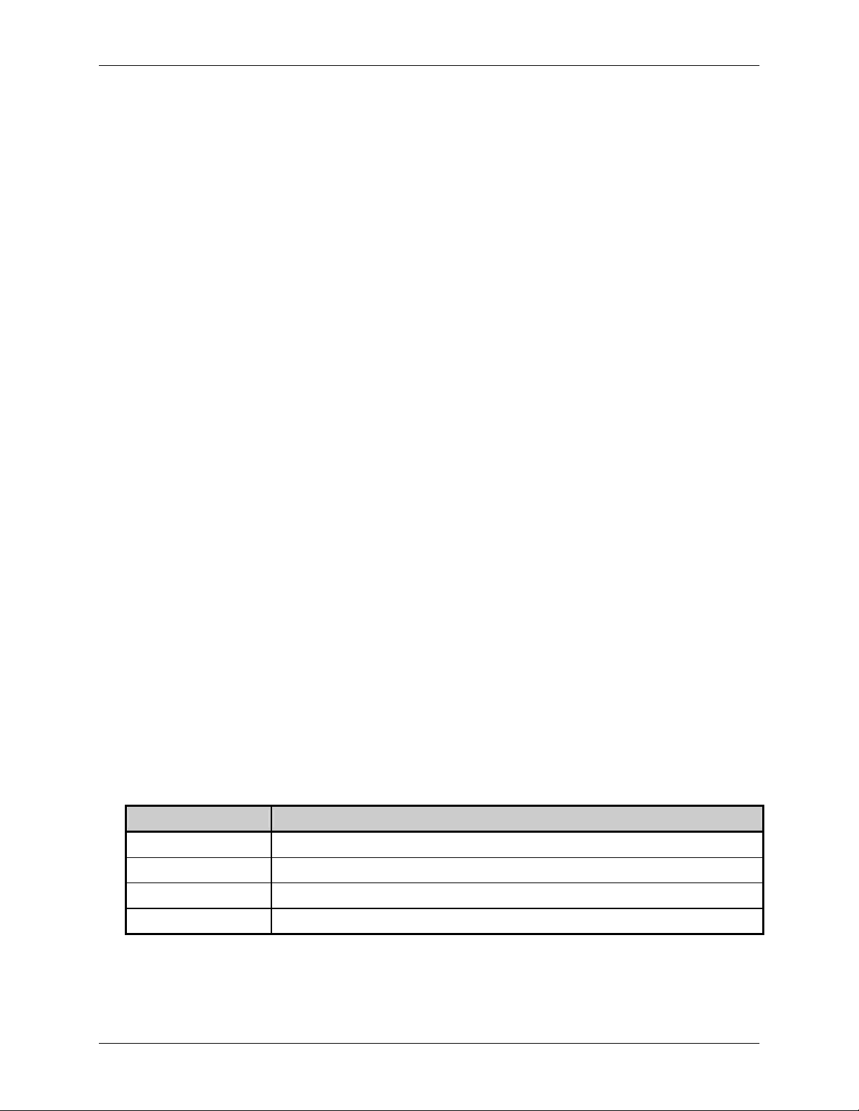
Printers (all models, unless where otherwise noted) Applicable Firmware Version*
A-Class 10.065
E-Class** 4.21
EX2 10.065
I-Class*** 8.03M2
H-Class 10.065
M-Class 8.03M2
W-Class*** 8.03M2
S-Class 6.02
*Firmware in RFID-equipped printers must be at version 08.043 or greater; see Note 1, below.
**For information regarding the E-3202 printer, see Note 2, below.
***Standard firmware version shown, while option-specific version numbers may differ.
Model distinctions, including configurations (i.e., Display-Equipped or Non-Display Models) and
equipped types (e.g., GPIO-1, graphics display, RFID, etc.), will be indicated in this text to differentiate
command compatibility. The appendices of this manual also contain details that cannot be ignored. The
use of any command will require checking for possible exclusionary conditions.
Notes: (1) See the <STX>KC command for information regarding attainment of the printer’s firmware version;
(2) Programming information for older S-Class and the Datamax legacy printers (Prodigy, DMX400, etc.)
(3) References to “Menu Settings” refer either to the printer’s internal set-up menu, or to the printer’s
(4) For backward compatibility purposes, the Class Series printers covered in this manual will ignore
(5) When updating firmware for E-Class version 4.10 and higher the printer must be in DPL Mode, not
(6) Where applicable, printer responses to a host device will depend upon the communication port, port
and then, if necessary, upgrade that firmware. Upgrades are available at ftp://ftp.datamax-oneil.com/.
can be found in the DPL Programmer’s Manual (part number 88-2051-01). Programming information for
the E-3202 can be found in E-3202 Programmer’s Manual (part number 88-2257-01). Both manuals can
be downloaded from our web site at http://www.datamax-oneil.com/
menu driven display system; please consult to the appropriate printer Operator’s Manual for details.
commands that are no longer processed; Appendix N lists these commands.
LINE mode, prior to sending the *.dlf file. See Appendix S for details.
settings, and cabling.
.
Class Series Programmer’s Manual 1
Page 16

Overview
This manual contains the following chapters and appendices:
OVERVIEW on page 1
Contents, organization, and conventions used in this manual; also includes a typical data flow
sequence for the printer.
CONTROL CODE COMMAND FUNCTIONS on page 7
Description of the attention-getter characters necessary for the printer to receive a command
sequence, and available alternate characters and line terminators.
IMMEDIATE COMMAND FUNCTIONS on page 9
Description of the commands, listed alphabetically, that perform status queries and printer control
commands.
SYSTEM-LEVEL COMMAND FUNCTIONS on page 15
Description of the commands, listed alphabetically, that control the printer and allow scalable font
and image downloads.
EXTENDED SYSTEM-LEVEL COMMAND FUNCTIONS on page 37
Description of the commands (listed alphabetically) that control the printer.
LABEL FORMATTING COMMAND FUNCTIONS on page 109
Description of commands, listed alphabetically, that control the position of text and images on the
media, print or store, and end the formatting process.
FONT LOADING COMMAND FUNCTIONS on page 129
Description of commands, listed alphabetically, used when downloading font data in PCL-4
compatible bit-maps.
GENERATING LABEL FORMATS on page 131
Description of the structure of records, the different types, and their use in generating label formats.
APPENDICES A THROUGH V on pages 147 through 281
These contain details that cannot be ignored including various tables, programming examples,
printer default values, and bar code symbology details. See the Table of Contents for specific
content information.
GLOSSARY on page 283
Definitions of words, abbreviations, and acronyms used in this manual.
Class Series Programmer’s Manual 2
Page 17

Overview
General Conventions
These are some of the conventions followed in this manual:
On the header of each page, the name of the chapter.
On the footer of each page, the page number and the title of the manual.
Names of other manuals referenced are in Italics.
Notes are added to bring your attention to important considerations, tips or helpful suggestions.
Boldface is also used to bring your attention to important information.
This manual refers to IBM-PC based keyboard command characters for access to the ASCII
character set. Systems based on different formats (e.g., Apple’s Macintosh™) should use the
appropriate keyboard command to access the desired ASCII character. See Appendix A for the
ASCII character set.
Computer Entry and Display Conventions
Command syntax and samples are formatted as follows:
The Courier font in boldface indicates the DPL command syntax, and Italics are used to indicate
the command syntax parameters.
Regular Courier font indicates sample commands, files and printer responses.
Square brackets ([ ]) indicate that the item is optional.
<CR> is used to identify the line termination character. Other strings placed between < > in this
manual represent the character of the same ASCII name, and are single-byte hexadecimal values
(e.g., <STX>, <CR>, and <0x0D> equal 02, 0D, and 0D, respectively).
Hexadecimal values are often displayed in ‘C’ programming language conventions (e.g., 0x02 =
02 hex, 0x41 = 41 hex, etc.)
Class Series Programmer’s Manual 3
Page 18
Overview
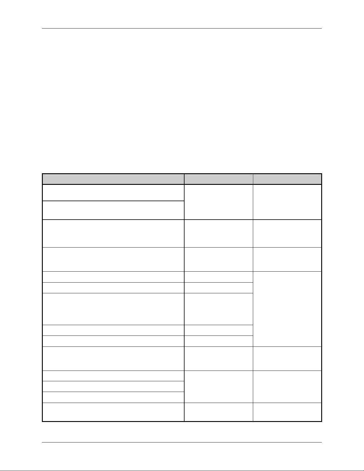
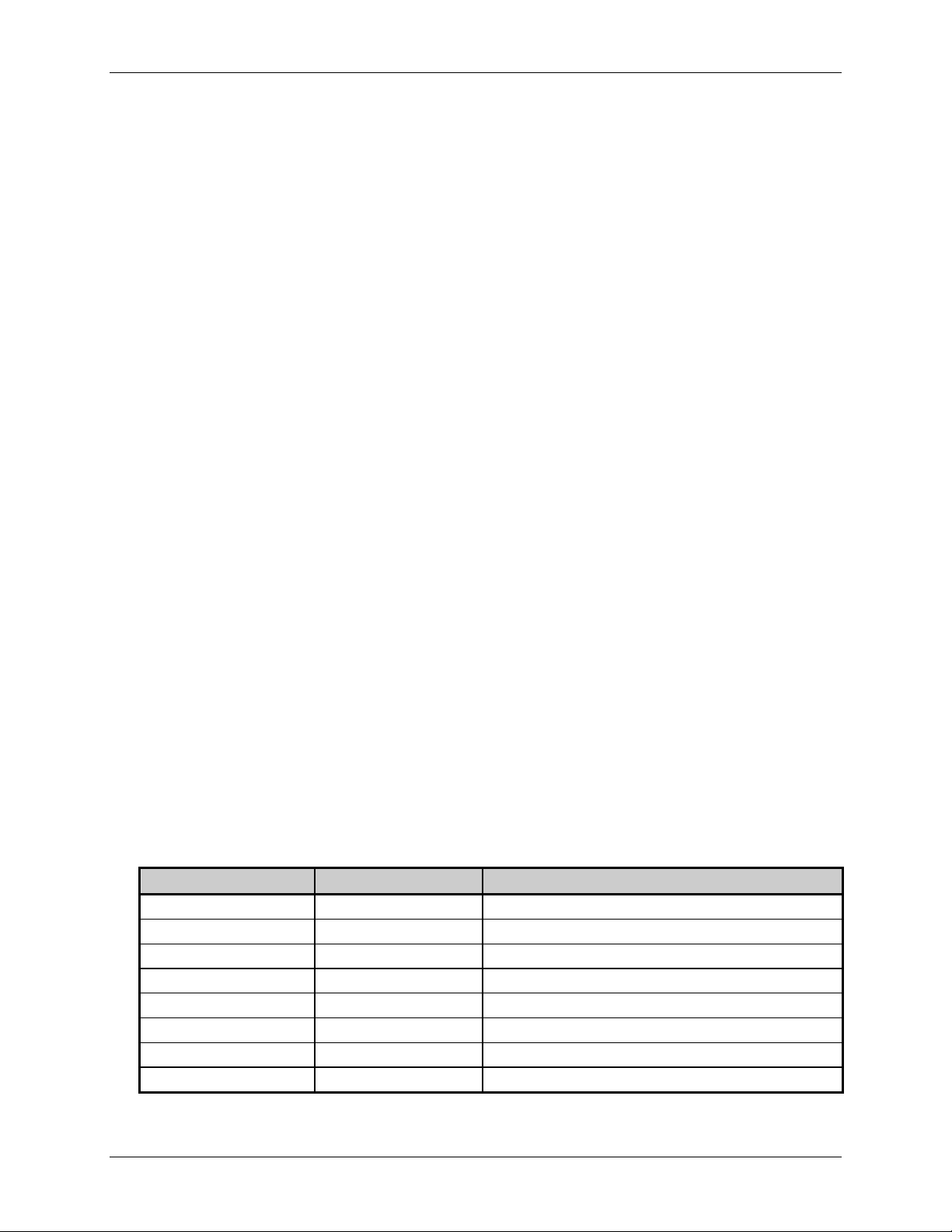
Typical Data Flow Sequence
The typical data flow sequence is summarized in the following bullets and detailed in the table below.
Printer Commands data is transmitted to the printer as shown in the table from left to right, top to bottom.
Status commands
Configuration commands
Download commands
Label format
Status commands
Label reprint commands
Memory cleanup
Printer Commands Description Notes
<SOH>A
<STX>WG
<STX>O220
<STX>n
<STX>V0
<SOH>D
<STX>IApImagename<CR>image data...data
<CR>
<STX>L
D11
131100000500050Typical text field 01
Q0001
E
<SOH>A
<STX>U01new data for field 01
<STX>E0005
<STX>G
“Status” commands: Get
Status, Request Memory
Module Storage
Information…
“Configuration”
commands, download
image…
“Download” commands,
image, fonts…
Begin label
Label Header record
Label Formatting Data
record –
Object type, orientation,
position, data
Label Quantity
Label Terminate record
Status command
Reprint with New Data
Records
Optional, bi-directional
communication required
for these commands.
See <STX>Kc to reduce
configuration commands
transferred
RAM (temporary) or
Flash (semi-permanent)
memory
Existing label formats
may be recalled. Label
header records are not
required
Optional, bi-directional
communication required
for these commands.
Used for fast re-prints
<STX>xImagename<CR>
<STX>zA
Class Series Programmer’s Manual 4
Memory cleanup
Typically used for
temporary storage
Page 19
Overview
Commands are available for retrieving stored label formats, updating data, and adding new data. These
techniques are used for increasing throughput. See <STX>G, Label Recall Command ‘r’, and Label Save
Command ‘s’.
Typical commands used in the various stages shown above are listed in the tables that follow.
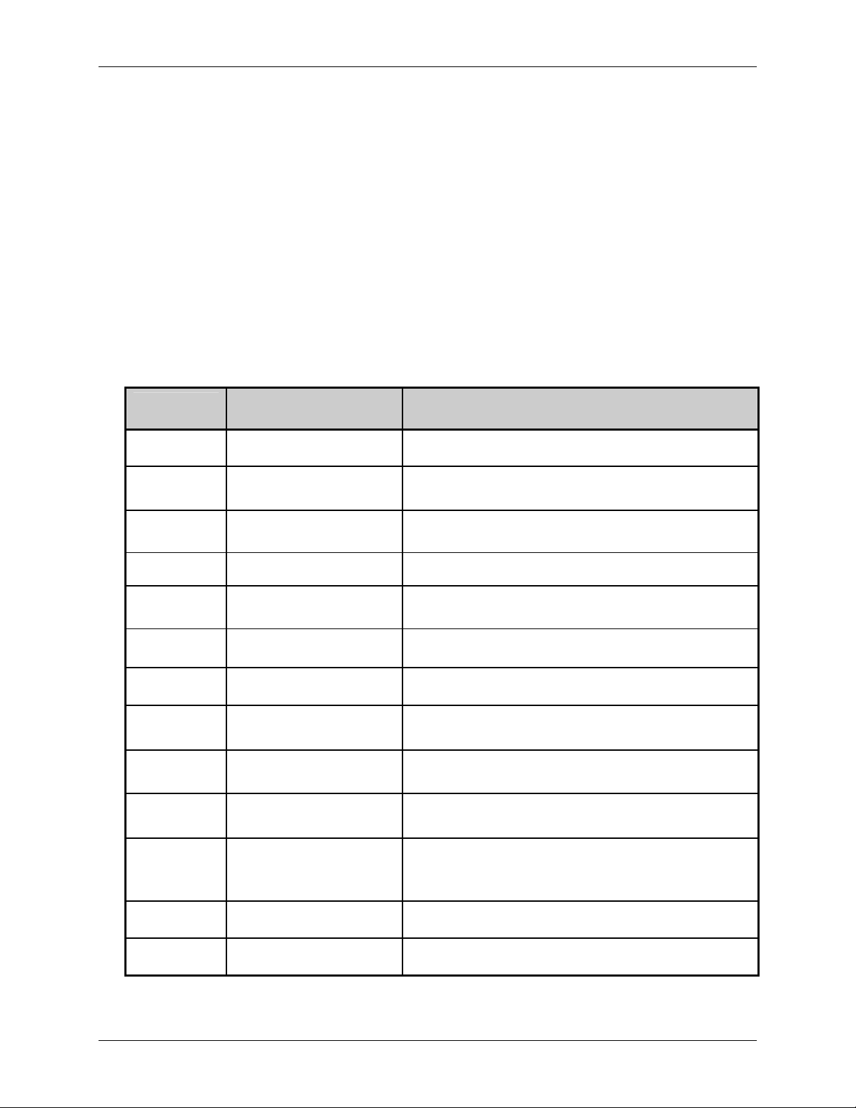
Configuration Commands
The following table lists some commands useful in controlling printer configuration. These
commands are generally effective only for the current power-up session; toggling power restores the
default configuration. See <STX>Kc for changes to the default power-up configuration. Changing the
default power-up configuration and saving objects in printer Flash memory can reduce the data
transmitted for each label and therefore improve throughput.
Configuration
Command
Name Function
<STX>A
<STX>d
<STX>c
<STX>e
<STX>Kf
<STX>Kc
<STX>F
<STX>M
<STX>m
<STX>n
<STX>O
Set Date and Time Set Date and Time
Set Double Buffer Mode
Set Continuous Paper Length
Force generation of multiple memory copies of label format;
usually not used
Must be 0000 for gap media; not used for reflective media
Set Edge Sensor Setup for gap or registration hole type stock
Set Present Distance
Determines label stop position, head relative. <STX>f edge
sensor relative equivalent command, older models
Configuration Set Determines default power-up configuration
Send Form Feed Sets the stop position of the printed label
Set Maximum Label Length
Set to Metric Mode
Set to Inch Mode
Length to search for next gap or reflective mark; not used
with continuous media
Subsequent measurements interpreted in metric (most units
mm/10). Label equivalent command can be used
Subsequent measurements interpreted in inches, most units
in/100, Label equivalent command can be used
Effect is not on label immediately following command since
Set Start of Print Position
media position is at Start of Print between labels; <STX>K
default position relative ± 64 in/100 maximum deviation
<STX>S
<STX>V
Set Feed Rate Blank label movement speed
Software Switch Enable optional hardware, cutter, present sensor
Class Series Programmer’s Manual 5
Page 20
Download Commands
Download
Command
Overview
Name Function
<STX>I
<STX>i
<ESC>
Download Image Download Image to selected memory module
Download Scalable Font Download Scalable Font to selected memory module
Download Bitmapped Font Download Bitmapped Font to selected memory module
Label Header Commands
These commands determine how the label formatting occurs, effect print quality and quantity. They
are typically issued immediately following the <STX>L start of the label format. The Format
Attribute (A) and the Offset (C, R) commands can be changed at any point between format records to
achieve desired effects.
Label Header
Command
A
C
D
Set Format Attribute
Column Offset
Set Width and Dot Size
Name
H
M
P
P
Q
R
S
Set Heat Setting
Set Mirror Mode
Set Print Speed
Set Backup Speed
Set Quantity
Set Row Offset
Set Feed Speed
Class Series Programmer’s Manual 6
Page 21
Control Code Command Functions
Introduction
The printer requires a special “attention-getter” character in order to receive a command sequence,
informing the printer that it is about to receive a command and the type of command it will be. Control
Commands, System-Level Commands, and Font Loading Commands have their own unique attentiongetter, followed by a command character that directs printer action.
Attention-Getters
The attention-getters (e.g., “SOH”) are standard ASCII control labels that represent a one character control
code (i.e., ^A or Ctrl A). Appendix A contains the entire ASCII Control Code Chart.
Attention-Getter ASCII Character Decimal Value HEX Value
Immediate Commands
System-Level Commands
Font Loading Commands
SOH 1 01
STX 2 02
ESC 27 1B
Table 2-1: Control Code Listings
Alternate Control Code Modes
For systems unable to transmit certain control codes, Alternate Control Code Modes are available.
Configuring the printer to operate in an Alternate Control Code Mode (selected via the Setup Menu, the
<STX>Kc command or, where applicable, the <STX>KD command) requires the substitution of Standard
Control Characters with Alternate Control Characters in what is otherwise a normal data stream.
Control Character Standard Alternate Alternate 2 Custom Command Type
SOH 0x01 0x5E 0x5E
STX 0x02 0x7E 0x7E
CR 0x0D 0x0D 0x7C
ESC 0x1B 0x1B 0x1B
“Count By”
[1]
See Label Formatting Commands, ^ set count by amount.
[1]
0x5E 0x40 0x40
User Defined Control
User Defined System
User Defined Line Termination
User Defined Font Loading
User Defined Label Formatting
Table 2-2: Alternate Control Code Listings
Note: Throughout this manual <SOH>, <STX>, <CR>, <ESC>, and ^, will be used to indicate the control codes.
The actual values will depend on whether standard or alternate control codes are enabled for the
particular application.
Class Series Programmer’s Manual 7
Page 22

Alternate Line Terminator Example
Control Commands
Alternate Control Codes provide for substitution of the line terminator, as well as the control characters
listed above. For example using Alternate 2, the line terminator <CR> (0x0D) is replaced by | (0x7C).
The following is a sample label format data stream for a printer configured for Alternate-2 Control Codes:
~L|1911A10001000101234560|X|~UT01ABCDE|~G|
Class Series Programmer’s Manual 8
Page 23

Immediate Command Functions
Introduction
When the printer receives an Immediate Command, its current operation will be momentarily interrupted
to respond to the command. Immediate Commands may be issued before or after System-Level
commands; however, they may not be issued among Label Formatting Commands or during font or
image downloading. Immediate Commands consist of:
1. Attention-Getter, 0x01 or 0x5E, see Control Codes.
2. Command Character
SOH # Reset
This command resets the printer. Resetting the printer returns all settings to default and clears both
the communications and printing buffers. The command also clears DRAM memory.
Syntax:
Printer Response: The printer will reset.
<SOH>#
<XON> T (The T may come before the <XON>)
SOH * Reset
(Display-Equipped Models only)
Class Series Programmer’s Manual 9
This command forces a soft reset of the microprocessor, resetting the printer, returning all factory
default values, and clearing the communication and print buffers.
Syntax:
<SOH>*
Printer Response: The printer will reset.
<XON> R (The R may come before the <XON>)
Page 24
Immediate Command Functions
SOH A Send ASCII Status String
This command allows the host computer to check the current printer status. The printer returns a
string of eight characters, followed by a carriage return. Each character (see below) indicates an
associated condition, either true (Y) or false (N). Byte 1 is transmitted first. See <SOH>F.
Syntax:
Sample:
Printer Response:
<SOH>A
<SOH>A
abcdefgh<CR>
Where:
Possible Values Interpretation Byte Transmit Sequence
a - Y/N Y = Interpreter busy (imaging) 1
b - Y/N Y = Paper out or fault 2
c - Y/N Y = Ribbon out or fault 3
d - Y/N Y = Printing batch 4
e - Y/N Y = Busy printing 5
f - Y/N Y = Printer paused 6
g - Y/N Y = Label presented 7
h - N N = Always No 8
Table 3-1: ASCII Status Bytes
SOH a Send ASCII Extended Status String
This command allows the host computer to check an extended current printer status. The printer
returns a string of seventeen characters, followed by a carriage return. Most characters (see below)
indicate an associated condition, either true (Y) or false (N). Byte 1 is transmitted first. See <SOH>F.
Syntax:
Sample:
Printer Response:
<SOH>a
<SOH>a
abcdefgh:ijklmnop<CR>
Class Series Programmer’s Manual 10
Page 25
Where:
Immediate Command Functions
Possible Values Interpretation Byte Transmit Sequence
a - Y/N Y = Interpreter busy (imaging) 1
b - Y/N Y = Paper out or fault 2
c - Y/N Y = Ribbon out or fault 3
d - Y/N Y = Printing batch 4
e - Y/N Y = Busy printing 5
f - Y/N Y = Printer paused 6
g - Y/N Y = Label presented 7
h - N N = Always No 8
- : : = Always : 9
i - Y/N Y = Cutter Fault 10
j - Y/N Y = Paper Out 11
k - Y/N Y = Ribbon Saver Fault 12
l - Y/N Y = Print Head Up 13
m - Y/N Y = Top of Form Fault 14
n - Y/N Y = Ribbon Low 15
o - Y/N Y = N (reserved for future) 16
p - Y/N Y = N (reserved for future) 17
Table 3-1: ASCII Status Bytes
SOH B Toggle Pause
This command toggles the printer’s paused state between on and off. (This is the same function
achieved by pressing the PAUSE Key on the printer.)
Syntax:
Sample:
Printer Response: This command will illuminate the Paused/Stop Indicator and/or indicate
<SOH>B
<SOH>B
PAUSED on the LCD or graphics display panel, suspend printing, and wait
until one of the following occurs:
The <SOH>B command is sent to the printer.
The PAUSE Key is pressed.
Upon which the printer will turn the Paused/Stop Indicator ‘Off’ and/or
remove PAUSED from the LCD or graphics display panel, then resume
operation from the point of interruption. (If the Receive Buffer is not full,
an <XON> character will be transmitted from the printer.)
Class Series Programmer’s Manual 11
Page 26

SOH C Stop/Cancel
Immediate Command Functions
This command performs the same function as pressing the STOP/CANCEL Key on the printer. This
function clears the current format from the print buffer, pauses the printer, and illuminates the
Paused/Stop Indicator. (The pause condition is terminated as described under <SOH>B.)
Syntax:
<SOH>C
Sample:
<SOH>C
Printer Response: This command will clear the print buffer, pause the printer, illuminate the
Paused/Stop Indicator and/or indicate PAUSED on the LCD or graphics
display panel, suspend printing, and wait until one of the following occurs:
• The <SOH>B command is sent to the printer; or
• The PAUSE Key is pressed.
Upon which the printer will turn the Paused/Stop Indicator ‘Off’ and/or
remove PAUSED from the LCD or graphics display panel. (If the Receive
Buffer is not full, an <XON> character will be transmitted from the printer.)
SOH D SOH Shutdown
(Non-Display Models only)
This commands the printer to ignore Immediate Commands (^A). The SOH shutdown command is
required before loading images or fonts because some may contain data sequences that could be
interpreted as Immediate Commands. After the SOH shutdown command is sent, Immediate
Commands can be turned back on by sending a valid SOH command three times, separated by a one
second delay between each command, or by manually resetting the printer. It is good practice to
check batch quantities (<SOH>E) to verify that the SOH commands are working.
Syntax:
Sample:
Printer Response:
<SOH>D
<SOH>D
This printer will ignore Immediate Commands (^A) until a valid SOH
command is received three times, separated by a one second delay between
each command; or, until the printer is manually reset.
Class Series Programmer’s Manual 12
Page 27
Immediate Command Functions
SOH E Send Batch Remaining Quantity
This command causes the printer to return a four-digit number indicating the quantity of labels that
remain to be printed in the current batch, followed by a carriage return. Communications latency may
cause this value to be higher than actual on some printers.
Syntax:
<SOH>E
Printer response:
nnnn<CR>
Where:
nnnn
- Are four decimal digits, 0-9999.
SOH e Send Batch Printed Quantity
This command causes the printer to return a four-digit number indicating the quantity of labels that
have been printed in the current batch, followed by a carriage return. Communications latency may
cause this value to be lower than actual on some printers.
Syntax:
<SOH>e
Printer response:
nnnn<CR>
Where:
nnnn
- Are four decimal digits, 0-9999.
SOH F Send Status Byte
This command instructs the printer to send a single status byte where each bit (1 or 0) represents one
of the printer’s status flags, followed by a carriage return (see below). If an option is unavailable for
the printer, the single bit will always be zero. See <SOH>A.
Syntax:
<SOH>F
Printer response format:
X<CR>
Where ‘X’ is 0 through 0xef with bits as indicated in the ‘Condition’ column below:
Bit
[1]
Value Condition
8 0 Always zero
7 1 or 0 Label presented
6 1 or 0 Printer paused
5 1 or 0 Busy printing
4 1 or 0 Printing batch
3 1 or 0 Ribbon out or Fault
2 1 or 0 Paper out or Fault
1 1 or 0 Command interpreter busy (imaging)
[1]
One is the least significant bit.
Class Series Programmer’s Manual 13
Page 28

Immediate Command Functions
Class Series Programmer’s Manual 14
Page 29
System-Level Command Functions
Introduction
The most commonly used commands are the System-Level Commands. These are used to load and store
graphics information, in addition to printer control. System-Level Commands are used to override default
parameter values (fixed and selectable) and may be used before or after Immediate Commands but cannot
be issued among Label Formatting Commands. System-Level Commands consist of:
1. Attention-Getter, 0x02 or 0x7E, see Control Codes.
2. Command Character
3. Parameters (if any).
STX A Set Time and Date
This command sets the time and date. The initial setting of the date will be stored in the printer’s
internal inch counter. This date can be verified by printing a Configuration Label.
Syntax:
Where:
Sample:
Printed response:
Notes: (1) When set to 000, the Julian date is automatically calculated; otherwise, the Julian date will print
(2) Printers without the Real Time Clock option lose the set time/date when power is removed.
(3) Response format is variable; see the Special Label Formatting Command <STX>T.
<STX>AwmmddyyyyhhMMjjj
w
mm
dd
yyyy
hh
MM
jjj
as that entered number, without daily increments. If factory defaults are restored the actual Julian
date will also be restored.
1 digit for day of week; 1 = Monday; 7 = Sunday
2 digits for month
2 digits for day
4 digits for year
2 digits for hour in 24 hour format
2 digits for minutes
3 digits for Julian date (numerical day of the year) / constant; see notes below.
<STX>A1020319960855034
Mon. Feb 3, 1996, 8:55AM, 034
Class Series Programmer’s Manual 15
Page 30
System-Level Command Functions
STX a Enable Feedback Characters
This command enables the feedback ASCII hex characters to be returned from the printer following
specific events after each completed batch of labels when using serial communications. The default
value is ‘Off’.
Syntax:
<STX>a
Printer response: Event dependent. (Also, see Appendix D for error codes.)
Where:
Event Return Characters
Invalid character 0x07 ( BEL )
Label printed 0x1E ( RS )
End of batch 0x1F ( US )
STX B Get Printer Time and Date Information
This command instructs the printer to retrieve its internal time and date information.
Syntax:
<STX>B
Sample:
<STX>B
Printer response format:
wmmddyyyyhhMMjjj<CR>
Where:
w
mm
dd
yyyy
hh
MM
jjj
1 digit for day of week; 1 = Monday
2 digits for month
2 digits for day
4 digits for year
2 digits for hour in 24 hour format
2 digits for minutes
3 digits for Julian date / constant*
* See <STX>A for details and restrictions.
Printer response sample:
1020319960855034<CR>
Class Series Programmer’s Manual 16
Page 31

System-Level Command Functions
STX c Set Continuous Paper Length
This command sets the label size for applications using continuous media. It disables the top-of-form
function performed by the Media Sensor. The sensor, however, continues to monitor paper-out
conditions. See <STX>M.
Syntax:
<STX>cnnnn
Where:
nnnn
- Specifies the length of the media feed for each label format, in
inches/100 or millimeters/10 (see <STX>m).
Sample:
<STX>c0100
This sample sets a label length of 100, which equals 1.00 inch (assuming Imperial Mode is selected).
Note: This command must be reset to zero for edge or reflective sensing operation.
STX d Set Double Buffer Mode
(Non-Display Models only)
This command, available for backward compatibility, enables double buffer mode. When printing
labels with incrementing, decrementing and replacement fields (see note below) the printer will only
erase and format those fields, leaving the rest of the label format untouched, and thus increasing
throughput. This command is only active if the labels being printed are less than half the maximum
size of the print buffer (see <STX>S).
Syntax:
<STX>d
Notes: (1) This command is generally not used because fast formatting is the normal operating mode when
the number of variable print fields (Label Formatting commands +, -, <, >, u) is less than or equal to
1/3 of the print field count total. In this case, the command will force fast formatting even when the
(2) The maximum label size is unaffected by this command.
(3) The <STX>s command restores normal (fast) formatting.
proportion of variable print fields is greater than 1/3 the total.
Class Series Programmer’s Manual 17
Page 32

System-Level Command Functions
STX E Set Quantity For Stored Label
This command sets the number of labels for printing using the format currently in the print buffer.
(The printer automatically stores the most recent format received in the buffer until the printer is reset
or power is removed.) When used in conjunction with the <STX>G command, this will print the
labels.
Syntax:
<STX>Ennnn
Where:
nnnn
- A four-digit quantity, including leading zeros.
Sample:
<STX>E0025
<STX>G
Printer response: 25 labels of the current format in memory will be printed.
Notes: (1) This command may be issued prior to a label format without a specified quantity, Qnnnnn.
Also, if a <CR> terminates the command, a five-digit quantity (nnnnn) can be entered.
(2) All models, except E-Class – Specifying 9999 as the four-digit quantity causes continuous
printing.
STX e Select Edge Sensor
This command enables transmissive (see-through) sensing for top-of-form detection of die-cut, and
holed (or notched) media. This Media Sensor will detect a minimum gap of 0.1 inches (2.5 mm)
between labels (see the Operator’s Manual for media requirements). Use the <STX>O command to
adjust the print position. This is the printer default setting at power-up or reset.
Syntax:
Note: This command is ignored when <STX>cnnnn is issued with a non-zero value for nnnn.
<STX>e
STX F Form Feed
This commands the printer to form feed to the next start of print.
Syntax:
<STX>F
Printer response: The printer will form feed.
Note: Following a reset, if the length of the first label fed is less than the label offset value (defined by
the <STX>O command) the printer will advance past that label until a top-of-form is detected, or
until the offset is reached.
Class Series Programmer’s Manual 18
Page 33

System-Level Command Functions
STX f Set Form Stop Position (Backfeed Command)
This sets the stop position of the printed label, allowing the label to stop at a point past the start-ofprint position. When the next label format is sent, the printer motor reverses direction to retract the
media to the start-of-print position. If quantities of more than one label are requested, the printer will
operate without backfeeding. A backfeed will then only occur when printing has stopped for a few
seconds.
Non-Display Models: The printer Option Control must be set (via the menu) to ‘Host’ for this
command to have effect.
Display-Equipped Models: This command is not honored, see <STX>Kf and <STX>Kc.
Syntax:
<STX>fnnn
Where:
nnn
- Is a three-digit distance from the Media Sensor, in inches/100 or
mm/10. This distance is independent of the start-of-print position
(<STX>O), yet it must be greater than the start-of-print position to
take effect.
Sample:
<STX>f230
The sample sets a stop position distance of 230 (2.3 inches from the Media Sensor’s eye).
STX G Print Last Label Format
This command prints a previously formatted label and restarts a canceled batch job following the last
processed label. This is used when there is a label format in the buffer. The <STX>E command is
used to enter the quantity. (If the <STX>E command is not used only one label will print.)
Syntax:
<STX>G
Class Series Programmer’s Manual 19
Page 34

System-Level Command Functions
STX I Input Image Data
This command must precede image downloading from a host computer to the printer. The data that
immediately follows the command string will be image data. If any of the 8-bit input formats are to
be used, it is necessary to disable the Immediate Command interpreter by executing an <SOH>D
command before issuing the <STX>I command. See Appendix O for more information. To print an
image, see Generating Label Formats.
A-Class (and H–Class models with a large display): A “ready mode” logo image can be input
using this command. The image must be stored on a Flash module. The image name must be
“logolab” (lowercase only) in the following DPL command. Also, printer power must be cycled
for the new image to appear. The available display area is 312 pixels wide by 94 pixels high. Images
larger than this specified width or height will be clipped along the right and/or bottom edges.
Note: The native format for storing downloaded PCX and BMP images is RLE-2, which results in a better
compression ratio for less module space usage when downloading gray-scale images and images
with large black or white areas.
Syntax:
<STX>Iabfnn…n<CR>data
Where:
a
- Memory Module Bank Select (see Appendix K).
b
- Data Type (optional), A or omit.
b Value:
A
Image Data Value Range:
ASCII Characters 0-9, A-F, (7 bit)
omitted 00-FF, (8 bit)
f
- Format Designator
f Designator:
F
B
7-bit Datamax-O’Neil image load file
.BMP 8-bit format (image flipped), black and
Format Type:
white (B&W)
b
I
i
P
p
.BMP 8-bit format (image as received), B&W
.IMG 8-bit format (image flipped), B&W
.IMG 8-bit format (image as received), B&W
.PCX 8-bit format (image flipped), B&W
.PCX 8-bit format (image as received), B&W
Sample:
nn…n
<CR>
data
<SOH>D
- Up to 16 characters used as an image name.
- 0x0d terminates the name.
- Image data
<STX>IDpTest <CR>
data...data <CR>
The sample instructs the printer to (1) receive an 8-bit PCX image sent by the host in an 8-bit data
format, (2) name the image ‘Test’, and (3) store it in memory module D (with a .dim file extension).
Class Series Programmer’s Manual 20
Page 35

System-Level Command Functions
STX i Scalable Font Downloading
The command structure for downloading TrueType (.TTF) scalable fonts (font files may be singlebyte or double-byte character systems) is as follows
:
Syntax:
<STX>imtnnName<CR>xx…xdata…
Where:
m
- Memory Module Designator to save this font to; see Appendix
K.
t
Type of scalable font being downloaded:
-
T = TrueType
nn
Two-digit font reference ID. Valid range is 50-99, 9A-9Z, 9a-9z,
-
(base 62 numbers).
Name
The title, up to 16 characters, for this font.
-
<CR>
0x0d terminates the Name.
-
xx…x
Eight-digit size of the font data, number of bytes, hexadecimal,
-
padded with leading zeros.
data
The scalable font data.
-
Sample:
<STX>iDT52Tree Frog<CR>000087C2data...
This sample downloads a TrueType font to module ‘D,’ and assigns it the Font ID of 52 with the
name “Tree Frog” and file extension .dtt. The size of the font data is 0x87C2 bytes long.
STX J Set Pause for Each Label
This command causes the printer to pause after printing each label. It is intended for use with the peel
mechanism or tear bar when the Present Sensor option is not installed. After removing the printed
label, the PAUSE Key must be pushed in order to print the next label. (The printer must be reset to
clear the <STX>J command.)
Syntax:
<STX>J
STX K Extended System-Level Commands
This is an expansion of the System-Level Command structure. See Extended System-Level
Commands for more information.
Class Series Programmer’s Manual 21
Page 36

System-Level Command Functions
STX k Test RS-232 Port
This command instructs the printer to transmit the Y character from the printer’s RS-232 port.
(Failure to receive Y could indicate an interfacing problem.)
Syntax:
<STX>k
Printer response:
Y
STX L Enter Label Formatting Command Mode
This command switches the printer to the Label Formatting Command Mode. Once in this mode, the
printer expects to receive Record Structures and Label Formatting Commands. Immediate, SystemLevel, and Font Loading commands will be ignored until the label formatting mode is terminated
with E, s, or X, (see Label Formatting Commands for additional information).
Syntax:
<STX>L
STX M Set Maximum Label Length
This command instructs the printer move media this distance in search of the top-of-form (label edge,
notch, black mark, etc.) before declaring a paper fault. A paper fault condition can occur if this setting
is too close (within 0.1 inch [2.54 mm]) to the physical length of the label. Therefore, it is a good
practice to set this command to 2.5 to 3 times the actual label length used. The minimum value should
be at least 5” (127 mm).
Syntax:
<STX>Mnnnn
Where:
nnnn
- Is a four-digit length, 0000-9999, in/100 or mm/10. Maximum
setting is 9999 (99.99 inches or 2540 mm). The default setting is
16 inches/ 406.4 mm
Sample:
<STX>M0500
The sample sets a maximum travel distance of 5 inches (unless the printer is in metric mode, see
<STX>m).
STX m Set Printer to Metric Mode
This command sets the printer to interpret measurements as metric values (e.g., <STX>c0100 will
equal 10.0 mm). The default is Imperial (see <STX>n).
Syntax:
<STX>m
Class Series Programmer’s Manual 22
Page 37

System-Level Command Functions
STX n Set Printer to Imperial Mode
This command sets the printer to interpret measurements as inch values (e.g., <STX>c0100 will
equal 1.00 inch). The printer defaults to this mode.
Syntax:
<STX>n
STX O Set Start of Print (SOP) Position
This command sets the point to begin printing relative to the top-of-form (the label’s edge as detected
by the Media Sensor). The printer will feed from the top-of-form to the value specified in this
command to begin printing.
This value operates independently of the <STX>f command.
Non-Display Models: The printer Options Control must be set (via the menu) to ‘Host’ for this
command to have effect.
Display-Equipped Models: If SOP Emulation is set to ‘enabled’ (via the menu), this command sets
the point where printing starts, emulating the selected legacy printer’s distance, as measured between
the media sensor and the print head burn line. In addition, regardless of the SOP Emulation setting,
the start of print position can be fine-tuned via the menu: Menu Mode / Print Control / Custom
Adjustments / Row Adjust.
Syntax:
<STX>Onnnn
Where:
nnnn
- Is a four-digit offset value in inches/100 or mm/10. The
“zero” setting is the default value, and settings below 50 are
adjusted back to the default value.
Non-Display Models: the default setting is 0220 in Imperial
Mode (0559 in Metric Mode).
Display-Equipped Models: the default setting is ‘Off’ and
the printer assumes the natural start of print position.
Sample (non-display
models):
<STX>O0300
The above sample sets a start of print position of 3.0 inches (unless in Metric Mode, see <STX>m).
Sample (displayequipped models):
<STX>O0210
The above sample will begin printing 0.1 inch closer to the leading edge of the label if the 220
(Allegro) SOP Emulation was selected, or 1.0 inch farther away from the leading edge if 110
(ProdPlus) SOP Emulation was selected.
Class Series Programmer’s Manual 23
Page 38

STX o Cycle Cutter
System-Level Command Functions
This command will cause the optional cutter mechanism to immediately perform a cut after all
previously received commands are executed. The cutter must be installed, enabled and the
interlock(s) closed for operation.
Syntax:
<STX>o
STX P Set Hex Dump Mode
This command instructs the printer to assume Hex Dump Mode. Instead of a formatted product, data
sent to the printer following this command will be printed in the raw ASCII format. To capture this
data, labels must be at least four inches (102 mm) long and as wide as the maximum print width. This
command has the same effect as turning the printer ‘On’ while pressing the FEED Key; however, no
Configuration/Test Pattern label will be printed. To return to normal operation the printer must be
manually reset.
Syntax:
<STX>P
STX p Controlled Pause
The controlled pause command will cause the printer to pause only after all previously received
commands are executed. This is often useful between label batches. (This command will not
clear the
pause condition, see <SOH>B).
Syntax:
<STX>p
STX Q Clear All Modules
This command instructs the printer to clear all of the Flash and DRAM modules (see the Operator’s
Manual of the corresponding printer for applicable module options). All stored data will be
destroyed.
<STX>Q
Syntax:
Class Series Programmer’s Manual 24
Page 39

STX q Clear Module
System-Level Command Functions
This command clears the selected Flash or DRAM module. If a module is corrupted during normal
operations (identifiable when the printer responds with a ‘No Modules Available’ message to a
<STX>W command), it must be cleared. All stored data will be destroyed.
Syntax:
<STX>qa
Where:
a
- Memory module designator, see Appendix K.
Sample:
<STX>qA
The sample clears memory module A.
Notes: (1) If a module directory intermittently returns the message ‘No Modules Available’ or if data
continuously becomes corrupt with the write protect switch on, the module may be at the end of its
service life. Before, however, concluding that a module is defective, cycle the printer’s power and
test the module.
(2) E-Class models: Some Flash Memory Expansion options must have Write Enable jumpers
installed to perform this command.
STX R Ribbon Saver On/Off
(Display-Equipped Models only)
This command enables the operation of the optional Ribbon Saver. It is the only command used to
control the Ribbon Saver. Its operation is continuous when enabled. The printer must be set to
thermal transfer (ribbon) printing mode then, during operation, the Ribbon Saver engages
automatically, lifting when the minimum amount of label white space is exceeded.
Syntax:
<STX>Rx
Where:
x
- Y - Enabled (Default = Menu selection.)
N - Disabled
Sample:
<STX>RY
The sample will turn the ribbon saver on.
Note: This command is ignored on units not equipped with the ribbon saver option.
Class Series Programmer’s Manual 25
Page 40

System-Level Command Functions
STX r Select Reflective Sensor
This command enables reflective (black mark) sensing for top-of-form detection of rolled butt-cut,
and fan-fold or tag stocks with reflective marks on the underside. This Media Sensor will detect a
minimum mark of 0.1 inches (2.54 mm) between labels (see the Operator’s Manual for media
requirements). The end of the black mark determines the top of form. Use the <STX>O command to
adjust the print position.
Syntax:
Default setting: Edge sensing
STX S Set Feed Speed
This command controls the output rate of the media when the FEED Key is pressed.
Syntax:
Where:
STX s Set Single Buffer Mode
(Non-Display Models only)
This command, available for backward compatibility, instructs the printer to use single buffer
operation. In single buffer mode, the printer will erase and format all fields. This, in turn, decreases
printer throughput when incrementing, decrementing, or replacement fields are used (see Label
Formatting Commands). See <STX>d.
Syntax:
<STX>r
<STX>Sn
n
- Is a letter value (see Appendix L).
<STX>s
Class Series Programmer’s Manual 26
Page 41
System-Level Command Functions
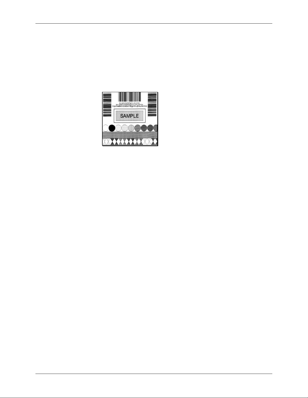
STX T Print Quality Label
This command instructs the printer to produce a Print Quality label, a format comprised of different
patterns and bar codes useful in printer setup. (On display-equipped models, this is also one of the
Quick Test formats.) To capture all printed information, use the labels as wide as the maximum print
width (see Appendix K) and at least four inches (102 mm) long.
Syntax:
<STX>T
Printer response (dot
patterns may vary):
STX t Test DRAM Memory Module
This command tests the DRAM module. The printer returns a one-line message stating the module
condition (no message is returned if a module is unavailable).
Syntax:
<STX>t
results
- Test results given as ‘Good’ or ‘Bad’.
Non-Display Models: The printer must be in Test Mode for the command to function. To enable the
Test Mode see the <STX>KD command.
Printer response format:
axxxK results<CR>
Where:
a
-2 = Slot B
xxx
- Module size in Kbytes
Display-Equipped Models: The printer must have Feedback Characters enabled for this command to
function. Feedback Characters can be enabled via the menu (see the Operator’s Manual for additional
information).
Printer response format:
Module A: xxxxK
Module B: xxxxK
Module D: xxxxK
DRAM Testedresults<CR>
DRAM Testedresults<CR>
DRAM Tested results<CR>
Where:
xxxx
- Module size in Kbytes.
Class Series Programmer’s Manual 27
Page 42

System-Level Command Functions
STX U Label Format String Replacement Field
This command places new label data into format fields to build a label. Two options are available:
Exact Length and Truncated Length.
To easily keep track of fields, place all of the fields to be updated with the command at the beginning
of the label format. A maximum of 99 format fields can be updated. Fields are numbered
consecutively 01 to 99 in the order received.
Exact Length Replacement Field Functions – The new data string must equal the original string
length and contain valid data. When the dynamic data is shorter than the length of the originally
defined data field, then field will be padded with blanks (or zero when the Format Record header
specifies a numeric bar code).
Syntax:
<STX>Unnss…s<CR>
Where:
nn
- Is the format field number, 2 digits.
ss…s
-
Is the new string data, followed by a <CR>
Exact Length Sample:
<STX>L
1A1100001000100DATA FIELD 1<CR>
161100001100110data field 2<CR>
161100001200120data field 3<CR>
Q0001
E
<STX>U01123<CR>
<STX>U02New data F2<CR>
<STX>E0002
<STX>G
The sample produces three labels. The first is formatted with the commands between <STX>L and
E. The next two labels print with the replacement data contained in the <STX>U commands (see
<STX>E and <STX>G). The bar code is the same length: 3 digits and nine spaces.
Truncated Length Replacement Field Functions – A variant of the <STX>U command includes the
truncate option ‘T’, where dynamic data shorter than the originally defined field length will not
padded and the original maximum field length is maintained for subsequent replacements.
Syntax:
<STX>UTnnss…s<CR>
Where:
nn
- Is the format field number, 2 digits.
T
- Truncate option
ss…s
-
Is the new string data, followed by a <CR>
be
Class Series Programmer’s Manual 28
Page 43
Truncated Sample:
System-Level Command Functions
<STX>L
1A1100001000100data field 1<CR>
161100001100110data field 2<CR>
161100001200120data field 3<CR>
Q0001
E
<STX>UT01123<CR>
<STX>U02New data F2<CR>
<STX>E0002
<STX>G
The sample produces three labels. The first is formatted with the commands between <STX>L and
E. The next two labels print with the replacement data contained in the <STX>U commands (see
<STX>E and <STX>G). The bar code is shortened; it only has three digits (and no spaces).
STX V Software Switch Settings
This command controls the printer options, where the appropriate value allows the option(s) to be
‘On’ or ‘Off.’ Each option has a corresponding bit whose value is ‘1’ when enabled. The tables below
indicate the bit assignments and corresponding command value needed to enable the desired
option(s).
Display-Equipped Models: Printer options are set by entering selections through the menu. The
software setting command allows two of these option settings to be modified without returning to the
menu.
Syntax:
Where:
Sample:
The sample corresponds to setting Bits 0 and 2, creating a command value of 5. When applied, this
enables the Present Sensor and Cutter options.
Bit Assignment Printer Option
<STX>Vn
n
- Is a single digit ASCII numeric value from 0-F. The value of
<STX>V5
n is used to override the power-up option settings. Reset or
power-up returns the printer to the original settings.
0 Cutter
1 N/A
2 Present Sensor
3 N/A
Table 4-1: Software Switch Bit Assignment
Use the bit assignment table above to determine the command value n in the binary table below (e.g.,
the command value 5 sets the bits 0 and 2 to ‘1’).
Class Series Programmer’s Manual 29
Page 44

System-Level Command Functions
Command Values for Bits Assigned
n Value
3 2 1 0
Bit
0 0 0 0 0
1 0 0 0 1
4 0 1 0 0
5 0 1 0 1
Table 4-2: Software Switch Binary
STX v Request Firmware Version
This command causes the printer to send its version string (this data is the same as that printed on the
configuration label). The version may be different from printer to printer.
Syntax:
Printer Response:
<STX>v
VER: 4308 – 06.06 07/09/2001 <CR>
Class Series Programmer’s Manual 30
Page 45

System-Level Command Functions
STX W Request Memory Module Information
This command requests a memory module directory listing. Results may vary depending on printer
class, model, or firmware version.
Syntax:
<STX>W[b][c]a
Where:
Sample:
b
c
a
<STX>WF
optional – list file size also
s
optional – list file extension also
e
Data type:
-
F
G
L
C
X
N
M
f
*
Downloaded font
=
Graphic (Image)
=
Label format
=
Configuration file
=
Language file
=
Plug-in
=
Miscellaneous type file
=
Resident fonts
=
All types
=
Printer response (taken from an H-Class with a downloaded true type font on Module D):
MODULE: D<CR>
S50 92244ttf50<CR>
AVAILABLE BYTES: 945152<CR>
MODULE: G<CR>
AVAILABLE BYTES: 852480<CR>
MODULE: X<CR>
AVAILABLE BYTES: 852480<CR>
MODULE: Y<CR>
AVAILABLE BYTES: 852480<CR>
Class Series Programmer’s Manual 31
Page 46

System-Level Command Functions
STX w Test Flash Memory Module
This command tests the Flash memory module. The time for each test will vary from 20 to 120
seconds, depending upon the size of the module. All stored data will be destroyed. If no module is
present, there will be no printer response.
Syntax:
<STX>wa
Where:
a
- Module designator; see Appendix K.
Printer response format:
Module A: xxxxK results
Where:
A
- Module tested.
xxxx
- Module size in kilobytes.
results
- Test results given as ‘Good’ or ‘Bad’.
Note: E-Class models: Some Flash Memory Expansion options must have Write Enable jumpers installed
to perform this command.
STX X Set Default Module
This command, typically used prior to the loading of PCL-4 bit-mapped fonts (see Font Loading
Commands), is designed to allow the user to select between modules when downloading information.
The default module is one of the following:
1. The first alpha designator of the existing modules if item 2 has not occurred.
2. The module selected by this command.
Syntax:
<STX>Xa
Where:
a
- Module designator; See Appendix K.
Sample:
<STX>XB
The sample sets ‘B’ as the default module.
Class Series Programmer’s Manual 32
Page 47

System-Level Command Functions
STX x Delete File from Module
This command removes a specific file from the specified module. The file name is removed from the
module directory and thus the file cannot be accessed. The actual storage space occupied by the file is
not released. To reclaim deleted file storage space use <STX>z to pack module.
Syntax:
<STX>xmtnn…n<CR>
Where:
m
- Module designator; see Appendix K.
t
- The file type identification code:
G
L
F
S
C
X
N
M
u
nn…n
- The file to delete, where:
Image file
=
Label format file
=
Downloaded bit-mapped font file
=
Downloaded scalable font file
=
Configuration file
=
Language file
=
Plug-in file
=
Miscellaneous file type
=
Unknown type – must use extension if applicable
=
Font (bitmapped), the three character font identifier;
Font (scalable), the two character font identifier;
Graphic name, up to sixteen alphanumeric characters; and,
Label format name, up to sixteen alphanumeric characters.
Sample:
<STX>xDS50<CR>
This sample deletes a downloaded scalable font with ID 50 from module D.
Class Series Programmer’s Manual 33
Page 48

System-Level Command Functions
STX Y Output Sensor Values
This command causes a sensor value response. When <STX>Y is received, the printer will respond
with the digitally converted values of the internal analog sensors (see below). To repeat the display of
values, send the printer a ‘SPACE’ character (20 hexadecimal); or, send <ESC> to terminate this
function.
Non-Display Models: The printer must be in Test Mode for the command to function. To enable the
Test Mode see the <STX>KD command.
Display-Equipped Models: The printer must have Feedback Characters enabled for this command to
function. (Feedback Mode [Characters] can be enabled via command or menu setting; see the
<STX>KcFM command or the Operator’s Manual for additional information).
Syntax:
<STX>Y
Printer response:
Thermistor ADC: 0048 Reflective ADC: 0000
Transmissive ADC: 0204 Paperout ADC: 0000 24 Volt ADC:
0217 Contrast ADC: 0093 TOF Adjust ADC: 0170 Ribbon
ADC: 0125 Battery Level: Good <CR>
Where:
Paperout ADC: 0225 indicates paper is present;
0000 indicates paper is not present.
Battery level: Good indicates a sufficient battery charge;
Low indicates an insufficient charge.
Notes: • Equipped sensors may vary with printer, model, and options.
• Some readings require printer-controlled paper movement to produce a meaningful value.
• Media Sensor readings require the appropriate sensor selection, transmissive (<STX>e) or
reflective (<STX>r), and label stock in the Media Sensor.
STX y Select Font Symbol Set
This command selects the scalable font symbol set. The selected symbol set remains active until
another symbol set is selected. See the <STX>KS command and Appendices E, I, and H for more
information. Option dependant, and not all symbol sets can be used with all fonts.
Syntax:
Where:
Sample:
The sample selects the PC-850 multilingual set.
<STX>ySxx
S
xx
- Byte-size designation; see Appendix H:
- Symbol set selection.
<STX>ySPM
S = Single byte symbol sets.
U = Double byte symbol sets.
Class Series Programmer’s Manual 34
Page 49
System-Level Command Functions
STX Z Print Configuration Label
This command causes the printer to produce a Database Configuration Label. To capture all printed
information, use the labels as wide as the maximum print width (see Appendix K) and at least four
inches (102 mm) long.
Syntax:
<STX>Z
Printer response:
Note: Printed information will vary according to printer, model, firmware version, and options.
FRI SEPTEMBER 026, 1997 19:29 244
VER: E4304 - 04.06 08/24/01
BOOT 83-2329-04A
CODE 83-2325-04F
FONT 83-2337-01A
CPLD 59-2157-01C
SYSTEM RAM CHECKS____ GOOD
SYSTEM RAM SIZE___ 2016 KBYTES
SYSTEM RAM AVAIL__ 1264 KBYTES
REG POWER SUPPLY__ NO
INPUT VALUES
PAPER_____________ 255
DARKNESS__________ 131
TRAN______________ 255
REFL______________ 149
RIBM______________ 87
THR_______________ 48
24V_______________ 223
DIRECT THERMAL
COMMUNICATIONS NOT DETECTED
9600,8,N
EDGE
SOP ADJUST________ 128
PRESENT ADJUST____ 128
TOF LOW___________ 0
TOF DELTA_________ 10
TOF GAIN__________ 10
OOS MAXVOLT_______ 2
COUNTER INFORMATION
ABSOLUTE VALUES 9-18-1999
LENGTH____ 773 INCHES
TIME______ 20 HOURS
RESETTABLE VALUES 9-22-1999
LENGTH____ 576 INCHES
TIME______ 10 HOURS
MEMORY CONFIGURATION
INTERNAL MODULE______ 128
SCALABLE FONTS_______ 64
LABEL SIZE 0410:02218 IN
STX z Pack Module
This command causes the printer to reclaim all storage space associated with all deleted files on the
specified module (see <STX>X and <STX>x).
Syntax:
<STX>zm
Where:
m
- The module identification character, see Appendix K.
Class Series Programmer’s Manual 35
Page 50

System-Level Command Functions
Class Series Programmer’s Manual 36
Page 51

Extended System-Level Command Functions
Introduction
Issued in the same context as System-Level Commands, the Extended System-Level Commands expand
certain System-Level Commands to provide extra degree of printer control.
STX K Memory Configuration (Non-Display Models only)
This command configures the available DRAM (including any installed optional DRAM) as a method
for managing printer memory. Memory can be assigned to specific entities or functions in units of
4KB blocks. The allocation(s) set by this command, draw from the same memory pool, affecting
maximum print length and label throughput (see note below). The printer executes the memory
configuration specified by the command during the next idle period following its receipt, and is stored
in Flash memory then reinstated upon a power-up or reset. If the total requested memory allocation
exceeds the configurable memory available, contains no fields, or for configurations not specified, the
command will be rejected and the printer will assume its previous configuration. Any of the three
fields are optional, and are separated by the colon. Brackets indicate optional fields.
Syntax:
<STX>Kix[:jy][:kz]<CR>
Sample:
<STX>KM0020:S0015<CR>
In the sample, memory is allocated 20*4*1024 bytes for module space and 15*4*1024 bytes for the
scalable cache.
Where: i, j, k are M, S, or W; x, y, z are four-digit maximum numbers of 4K byte blocks or
inches/100 or (mm/10) as described below.
M Represents the start of a sequence (up to five characters) that assigns memory to the Internal
Module. If this field does not appear, then the Internal Module is not affected. If no Internal
Module exists, it will be created and formatted. Existing Internal Modules will be erased, resized and formatted. The number that follows the M is a decimal number (up to four digits) that
specifies the size in 4KB blocks of memory to assign to the Internal Module. A value of “0000”
will delete the Internal Module (see Appendix J for additional information).
S Represents the start of a sequence (up to five characters) that assigns the amount of internal
memory allocated to the smooth scalable font processor. This field is optional; if it does not
appear, the current amount of memory assigned to the smooth scalable font processor will
remain unchanged. The allocation must be at least 15 (60KB) to print scalable fonts, and at least
30 for double-byte fonts. The number that follows the S is a decimal number (up to four digits)
that specifies the size in 4 KB blocks to assign to the smooth scalable font processor. Any value
less than the minimum requirement results in the amount assigned to be zero (0), thereby
disabling the printing of smooth scalable fonts. The recommended value is 0025 (100KB).
Class Series Programmer’s Manual 37
Page 52
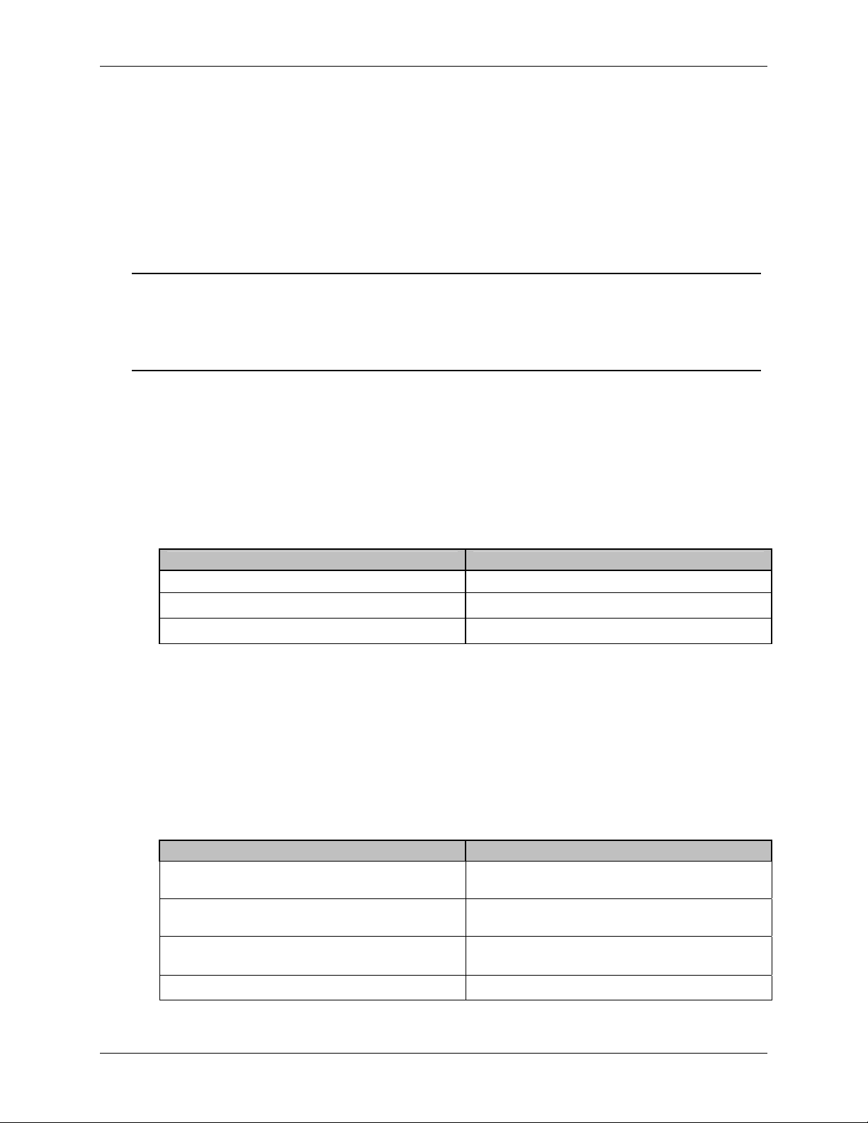
Extended System-Level Command Functions
W Represents the start of a sequence (up to five characters) that sets the printable label width.
Setting a width smaller than the natural (maximum) width of the printer effectively extends
printable label length. This field is optional; if it does not appear, the current printable label
width is left unchanged. The number that follows the W is a decimal number (up to four digits)
that specifies the printable label width in either 100
ths
of an inch or in millimeters, depending on
the current units setting of the printer (imperial or metric). If the value specified exceeds the
printable width of the printer, the printable label width is set to the maximum. If the value
specified is less than the minimum value allowed (200) then the printable label width is set to the
STX K}E Empty Sensor Calibration (Non-Display Models only)
minimum allowed value.
Notes: (1) Label printing requirements may be computed as bytes (label print length * width allocation *
print head resolution / 8). For maximum throughput, the memory allocated should allow for a
minimum of three times the computed requirement, or the available label length (as determined by
<STX>KQ command) should be three times the label print length.
(2) These commands will result in a system reset for the EX2.
This command causes the printer to determine and save the calibration value for an empty media
sensor condition. This calibration function should be performed when no material is installed in
the media sensor. Depending upon the printer model, different front panel LED flash sequences
and printer responses (below) will indicate calibration progress and outcome; see the
corresponding printer operator manual for LED flash sequences details.
Printer Response Alternate
REMOVE STOCK[CR ] N/A
ENTER TO CONTINUE[CR] N/A
PASSED CALIBRATION[CR] FAILED CALIBRATION[CR]
STX K}M Manual Media Calibration (Non-Display Models only)
This command causes the printer to save the sampled calibration values as an operator places
different portions of label stock within the media sensor. Depending upon the printer model,
different front panel LED flash sequences and printer responses (below) will indicate calibration
progress and outcome; see the corresponding printer operator manual for LED flash sequences
details. Sending <ESC> to the printer instead of <CR> will terminate the process and leave the
TOF Sensor values unchanged.
Printer Response Alternate
LOAD STOCK[CR ]
ENTER TO CONTINUE[CR ]
LOAD MARK[CR ]
ENTER TO CONTINUE[CR ]
REMOVE STOCK[CR ]
ENTER TO CONTINUE[CR ]
PASSED CALIBRATION[CR ] FAILED CALIBRATION[CR ]
LOAD GAP[CR ]
N/A
N/A
Class Series Programmer’s Manual 38
Page 53

Extended System-Level Command Functions
STX K}Q Quick Media Calibration (Non-Display Models only)
This command causes the printer to move media, sample, and then save sensor samples as
calibration values. This calibration function should be performed with media installed in the
printer. Depending upon the printer model, different front panel LED flash sequences and printer
responses (below) will indicate calibration progress and outcome; see the corresponding printer
operator manual for LED flash sequences details.
Printer Response Alternate
FAILED CALIBRATION[CR ]
ADJUST GAIN SETTING[CR ]
PASSED CALIBRATION[CR ] FAILED CALIBRATION[CR ]
N/A
STX KaR Read Data from RFID Tag
(Direct Mode – Generic Read/Write Interface)
This command instructs the RFID device to read data from the tag and then place that data into a
replaceable field. It is expected that the tag transponder will be within the read / write distance of the
RFID programming device; otherwise, “Void” will be printed in the text or bar code label field.
Syntax:
<STX>KaRAaaabbbcdee<CR>
Where:
A
- Optional – for data in the ASCII format.
aaa
- The number of bytes to read.
bbb
- HF - Starting block number (000 maximum block number).*
UHF – Should be 000.
Sample:
c
d
ee
<STX>L
1911A1802000010TEXT
U
X
<STX>KaR0000010001
<STX>G
- Command 1. Reserved. Should be 0.
- Command 2. Reserved. Should be 0.
- Field number in which to place the data (must be 01, 02, 03, etc.)
matching the order of Label Formatting command U.
Note: The 00 value will send read data to the host with no printing.
The sample creates a replaceable text field (01), recalls data from the RFID tag block zero (reading
only one block), and prints the data in the location specified by the replaceable field. Since there are
two digits per each hex value, replaceable fields should be twice as long than if using ASCII data
(e.g., the character “A” would be returned as “41”).
* Dependent upon transponder manufacturer.
Class Series Programmer’s Manual 39
Page 54

Extended System-Level Command Functions
STX KaW Write Data to RFID Tag
(Direct Mode – Generic Read/Write Interface)
This command instructs the RFID device to write data to the tag. It is expected that the tag
transponder will be within the read / write distance of the RFID programming device; otherwise, a
warning will occur and a warning message (Read / Write Fail) will be displayed.
Syntax:
<STX>KaWAaaabbbcdee…e<CR>
Where:
Aaaa
- Optional – for data in the ASCII format, followed by the byte
count (000-999).
bbb
- HF – Starting block number (000 maximum block number).*
UHF – Should be 000.
c
- Command 1. Reserved for Future (should be 0)
d
- Command 2. Reserved for Future (should be 0)
ee…e
- Data to be encoded on RFID tag (HF – the last used block will be
null-padded, if necessary).
Note: UHF ASCII formats must be 8 or 12 characters; and, UHF
Hexadecimal formats must be 16 or 24 character pairs.
Sample:
<STX>KaW0000054455354[CR]
The sample writes the data “TEST” at block zero.
* Dependent on transponder manufacturer.
STX Kb Backfeed Time Delay
(Non-Display Models only)
The backfeed time delay command controls the time a printed label is allowed to remain “presented”
before being retracted to the start of print position.
Syntax:
<STX>Kbnnn<CR>
Where:
nnn
- Seconds/10
Class Series Programmer’s Manual 40
Page 55

Extended System-Level Command Functions
STX KC Get Configuration
This command returns the configuration of the printer. The form of the returned data is similar to that
of a printed Configuration Label. This command should be parsed by KEYWORDS, not by
Character POSITIONS. Each line is terminated by a CR (0x0d) & LF (0x0a). Datamax-
O’Neil will make every effort to keep Keyword consistent.
Syntax:
<STX>KC<CR>
Printer response:
CONFIGURATION
TUE 02:01PM
01AUG2005
PRINTER KEY:
4308-TB10-010327494
APPLICATION
VERSION:
83-2284-06E
06.06 07/09/2001
BOOT LOADER:
83-2269-03D 03.04
10/30/2000
SYSTEM INFORMATION
PRINT BUFFER SIZE:
280 in.
FLASH SIZE:
4 MB
RAM TEST:
PASS
OPTIONAL
LANGUAGES:
FRANCAIS
ITALIANO
DEUTSCH
ESPAÑOL
CONFIGURATION
FILE:
NONE
MEDIA SETTINGS
MEDIA TYPE
THERMAL TRANSFER
SENSOR TYPE
GAP
LABEL LENGTH
04.00 in.
MAXIMUM LABEL
LENGTH
•30.00 in.
PAPER OUT DISTANCE
00.25 in.
LABEL WIDTH
4.16 in.
SENSOR CALIBRATION
PAPER SENSOR LEVEL
144
GAP SENSOR LEVEL
30
EMPTY SENSOR LEVEL
0
SENSOR GAIN
10
PRINT CONTROL
HEAT
10
PRINT SPEED
6.0in/sec
FEED SPEED
6.0in/sec
REVERSE SPEED
4.0in/sec
ROW OFFSET
00.00 in.
COLUMN OFFSET
00.00 in.
PRESENT DISTANCE
0.00 in.
CUSTOM
ADJUSTMENTS:
DARKNESS
32
ROW ADJUST
64 DOTS
COLUMN ADJUST
0 DOTS
PRESENT ADJUST
64 DOTS
PRINTER OPTIONS
MODULES
A: NOT INSTALLED
B: NOT INSTALLED
D: FORMATTED
F: NOT INSTALLED
G: FORMATTED
X: FORMATTED
Y: 83-2296-01C
Z: NOT INSTALLED
PRESENT SENSOR
NOT INSTALLED
CUTTER
NOT INSTALLED
GPIO PORT:
NOT INSTALLED
SYSTEM SETTINGS
FACTORY SETTING
FILE
NONE
INTERNAL MODULE
1024 KB
DEFAULT MODULE
D
SCALEABLE FONT
CACHE
312 KB
SINGLE BYTE
SYMBOLS
PC-850
MULTILINGUAL
DOUBLE BYTE
SYMBOLS
UNICODE
ABSOLUTE COUNTER
3782 in.
27MAR2001
RESETTABLE COUNTER
205 in.
27MAR2001
FORMAT ATTRIBUTES
XOR
IMAGING MODE
MULTIPLE LABEL
PAUSE MODE
DISABLED
SELECT SECURITY
DISABLED
PEEL MODE
DISABLED
UNITS OF MEASURE
IMPERIAL
SOP EMULATION
DISABLED
BACK AFTER PRINT
DISABLED
MENU LANGUAGE
ENGLISH
COMMUNICATIONS
SERIAL PORT A:
BAUD RATE
9600 BPS
PROTOCOL
BOTH
PARITY
NONE
DATA BITS
8
STOP BITS
1
SERIAL PORT B:
NOT INSTALLED
PARALLEL PORT A:
Note: Formatted form of displayed information will vary with printer, model, firmware version, and equipped
options.
PORT DIRECTION
UNI-DIRECTIONAL
PORT STATUS
DISABLED
PARALLEL PORT B:
PORT DIRECTION
BI-DIRECTIONAL
PORT STATUS
DISABLED
NIC ADAPTER:
DMXNET INACTIVE
HOST SETTINGS:
HOST TIMEOUT
10 SEC
CONTROL CODES
STANDARD CODES
FEEDBACK
CHARACTERS
DISABLED
ESC SEQUENCES
ENABLED
HEAT COMMAND
ENABLED
SPEED COMMANDS
ENABLED
DIAGNOSTICS
HEX DUMP MODE
DISABLED
PRINT TEST
RATE(min)
0
SENSOR READINGS
THR TRAN RIBM 24V
132 141 159 178
PS HD RANK
000 254 000
RIBBON SENSOR
LIMITS
RIBBON ADC LOW
105
RIBBON ADC HIGH
182
END OF LIST
Class Series Programmer’s Manual 41
Page 56

Extended System-Level Command Functions
STX Kc Configuration Set
This command specifies the Power-up Configuration parameter values for the printer and is
equivalent to using other system commands followed by the <SOH>U. This command is intended
for easily configuring a custom setup, but NOT
for dynamic configuration changes.
Configuration commands are examined for differences relative to the current configuration; the
command has no impact when there are no differences. Display-equipped models will reset upon
completion of a command stream containing parameter value changes; non-display models perform
this reset only for certain functions, such as memory allocation. In any case, no commands should be
sent to the printer until this reset is complete. These are some highlights of the command:
These parameter values are equivalent to changing the respective menu settings and do not affect
the factory default settings of the printer.
If separated by a semi-colon (;), multiple parameter values may be sent in a single command
stream; see sample below.
All values are stored in Flash memory and remain in effect until new values are received or until
factory defaults are restored.
If system commands are sent that override the Power-up Configuration value(s), the Power-up
Configuration value(s) will be restored the next time the printer is powered ‘On’ or reset.
These parameters are the same as those found in the Setup Menu (non-display models), or as
those found in the Menu System (display-equipped models). The respective functions are
documented in the appropriate Operator’s or Maintenance Manual. Not all commands are
effective on all Class printers.
Note: Illegal or out of range parameter values may have unpredictable results. In addition, Media sensing
scaling values, TOF Bias, etc. may not be effective on other printers of the same type due to
hardware tolerances.
Syntax:
<STX>Kcaa
val1[;aaIvalI][;aanvaln]<CR>
1
aa
Where:
aaI, aan
1,
- Are two letter parameter names.
val
1,
val
I,
val
- Are parameter values, with ranges appropriate for
n
the associated parameter.
Sample:
<STX>KcPA120;CL600;STC<CR>
The sample sets the Present Adjust to 120 dots, the Continuous Label Length to 6 inches, and the
Sensor Type to Continuous.
The following table (constructed alphabetically by parameter name) summarizes the different
Configuration Set command parameters, value ranges, valid printer models, and menu item and
command equivalents (where applicable). If no command equivalent is given, or where general
clarification is necessary for the command, descriptions (listed alphabetically by parameter
pneumonic) immediately follow this table.
Class Series Programmer’s Manual 42
Page 57

Extended System-Level Command Functions
Configuration Set Commands
<STX>Kc
Parameter Name
Alignment Length
Backup After Print
Backup Delay
Backup Label
Backup (Reverse) Speed
British Pound
Parameter
Pneumonic
AL
BA
BD
BL
BS or bS
BP
Value /
Range
Units /
Interpretation
Applicable
Printer Type
Menu Item Equivalent
or Menu Item Number
Command
Equivalent
Non-Display 19
0 – 999 1/100 inch
N/A
Non-Display 18
Display-Equipped System Settings
N/A
Y, N
Y = Enabled,
N = Disabled
EX2 N/A
0 – 255 1/50 second Display-Equipped System Settings N/A
0 = Disabled,
0, 3, 4
3 = Active Low,
Display-Equipped Printer Options N/A
4 = Active High
alpha
character
Model specific ranges;
see Appendix L.
Display-Equipped Print Control
pa
EX2 N/A
Display-Equipped
N/A N/A
EX2
Y, N
Y = Enabled,
N = Disabled
Buzzer Enable
BZ
Y, N
Y = Enabled,
N = Disabled
A-Class System Settings
N/A
Table 5-1: Configuration Set Commands
Class Series Programmer’s Manual 43
Page 58

<STX>Kc
Parameter Name
Parameter
Pneumonic
Value /
Range
Extended System-Level Command Functions
Units /
Interpretation
Applicable
Printer Type
Menu Item Equivalent
or Menu Item Number
Command
Equivalent
1]
Column Adjust
[
Column Adjust Fine Tune
Column Offset
Comm Heat Commands
CA
CF
CO
CH
Resolution specific;
see Appendix K,
xxx dots
and see
Column Adjust Fine
Tune
+ / – dots
Resolution specific;
see Appendix K.
0 – 9999 1/100 in.
Y, N
1, 0
Y, N
Y = Enabled,
N = Disabled
1 = Enabled,
0 = Disabled
Y = Enabled,
N = Disabled
Display-Equipped Print Control
Non-Display 28
Non-Display 7
Display-Equipped Print Control
EX2 N/A
Display-Equipped Print Control
EX2 N/A
Display-Equipped Communications
Non-Display 26
Non-Display 25
Display-Equipped Communications
N/A
N/A
Cnnnn
N/A
Comm Speed Commands
CS
1, 0
1 = Enabled,
0 = Disabled
Non-Display 25
Non-Display 26
N/A
Table 5-1: Configuration Set Commands (continued)
Class Series Programmer’s Manual 44
Page 59
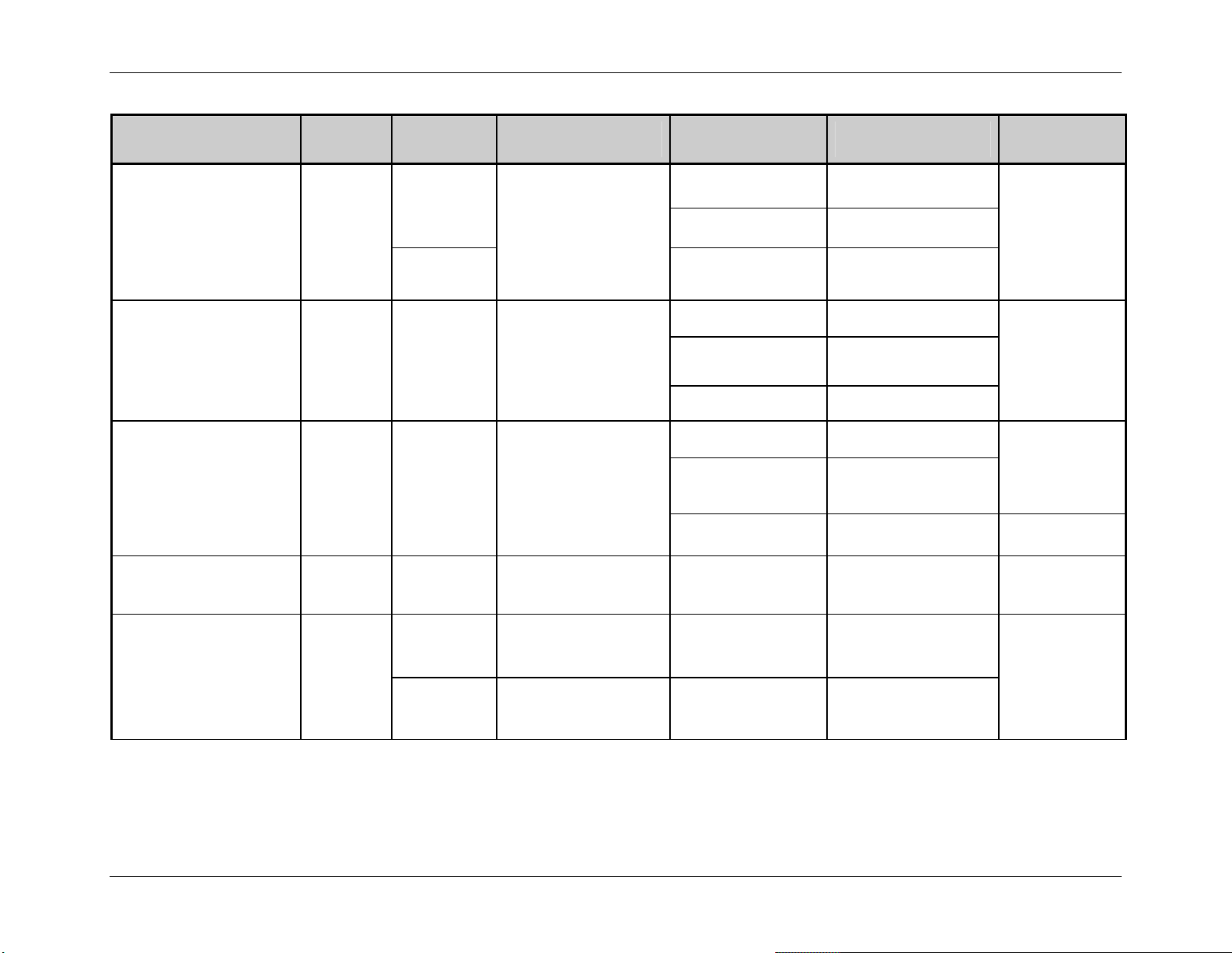
<STX>Kc
Parameter Name
Comm TOF Commands
Parameter
Pneumonic
CT
Extended System-Level Command Functions
Value /
Range
Y, N
0 – 255
(128 nominal)
Units /
Interpretation
Y = Enabled,
N = Disabled
Applicable
Printer Type
Menu Item Equivalent
or Menu Item Number
Display-Equipped Communications
EX2 N/A
Non-Display
(except EX2)
27
Display-Equipped Media Settings
Command
Equivalent
N/A
Continuous Label Length
Control Codes
Cut Behind
Cutter Equipped
CL
CC
CB
CE
0 – 9999 1/100 in.
Non-Display 12
Non-Display 10
Display-Equipped Communications
S = Standard,
S, 1, 2
1 = Alternate,
Non-Display 11
2 = Alternate-2
Non-Display 9
0 – 9 Queued label count Display-Equipped Printer Options N/A
A or Y = Auto,
A/Y, E, N/D
E = Enabled,
Display-Equipped Printer Options
N or D = Disabled
A = Auto,
A, E/Y, N
E or Y = Enabled,
Non-Display 4
N = Disabled
Table 5-1: Configuration Set Commands (continued)
<STX>c
N/A
<STX>KD
<STX>V
Class Series Programmer’s Manual 45
Page 60

<STX>Kc
Parameter Name
Parameter
Pneumonic
Darkness
Default Module DM
DK
Value /
Range
Extended System-Level Command Functions
Units /
Interpretation
Applicable
Printer Type
Menu Item Equivalent
or Menu Item Number
Display-Equipped Print Control
1 – 64 N/A
EX2 N/A
D, G Display-Equipped System Settings
Module Letter
[3]
A, B
N/A
EX2
Command
Equivalent
N/A
<STX>X
Delay Rate
(Test Label Formats)
Disable Symbol Set
Selection
Double Byte Symbol Set
DPI Emulation
Empty Sensor Level
End Character
DR 0 – 120 Seconds Display-Equipped Diagnostics N/A
NS Y, N
DS
2-Byte alpha
character
Y = Enabled,
N = Disabled
AA – ZZ, printer
resident symbol set
Non-Display N/A N/A
Display-Equipped System Settings
<STX>y,
ySxx
EX2 N/A
DE
200, 300,
400, 600
Dots per inch
300/400/600 DPI
Display-Equipped
System Settings N/A
Display-Equipped Media Settings
EV
0 – 255 N/A
N/A
EX2 N/A
Display-Equipped
EN
D N/A
N/A N/A
EX2
Table 5-1: Configuration Set Commands (continued)
Class Series Programmer’s Manual 46
Page 61

<STX>Kc
Parameter Name
End Of Print
Parameter
Pneumonic
EP
Value /
Range
1, 2, 3, 4
Extended System-Level Command Functions
Units /
Interpretation
Applicable
Printer Type
1 = Low Pulse,
2 = High Pulse,
3 = Active Low,
Display-Equipped Printer Options N/A
4 = Active High
Menu Item Equivalent
or Menu Item Number
Command
Equivalent
ESC Sequences
Exact Time
Fault Handling
Feed Speed
Feedback Mode
Font Emulation
ES
ET
FH
SS or sS
FM
FE
Display-Equipped Communications
Y, N
Y = Enabled,
N = Disabled
EX2 N/A
Y, N
Y = Enabled,
N = Disabled
Non-Display
(except EX2)
Display-Equipped System Settings
L, D, R, B See Table 5-2.
EX2 N/A
Non-Display 24
Alpha
character
Y, N
Model specific ranges;
see Appendix L.
Y = Enabled,
N = Disabled
Display-Equipped Print Control
Display-Equipped Communications
EX2 N/A
Display
Non-Display
0, 1, 2
0 = No Substitution
1 = Sub CG Times SA0
2 = Sub User S50
Table 5-1: Configuration Set Commands (continued)
N/A
24 N/A
N/A
Sa
<STX>a
N/A N/A
Class Series Programmer’s Manual 47
Page 62
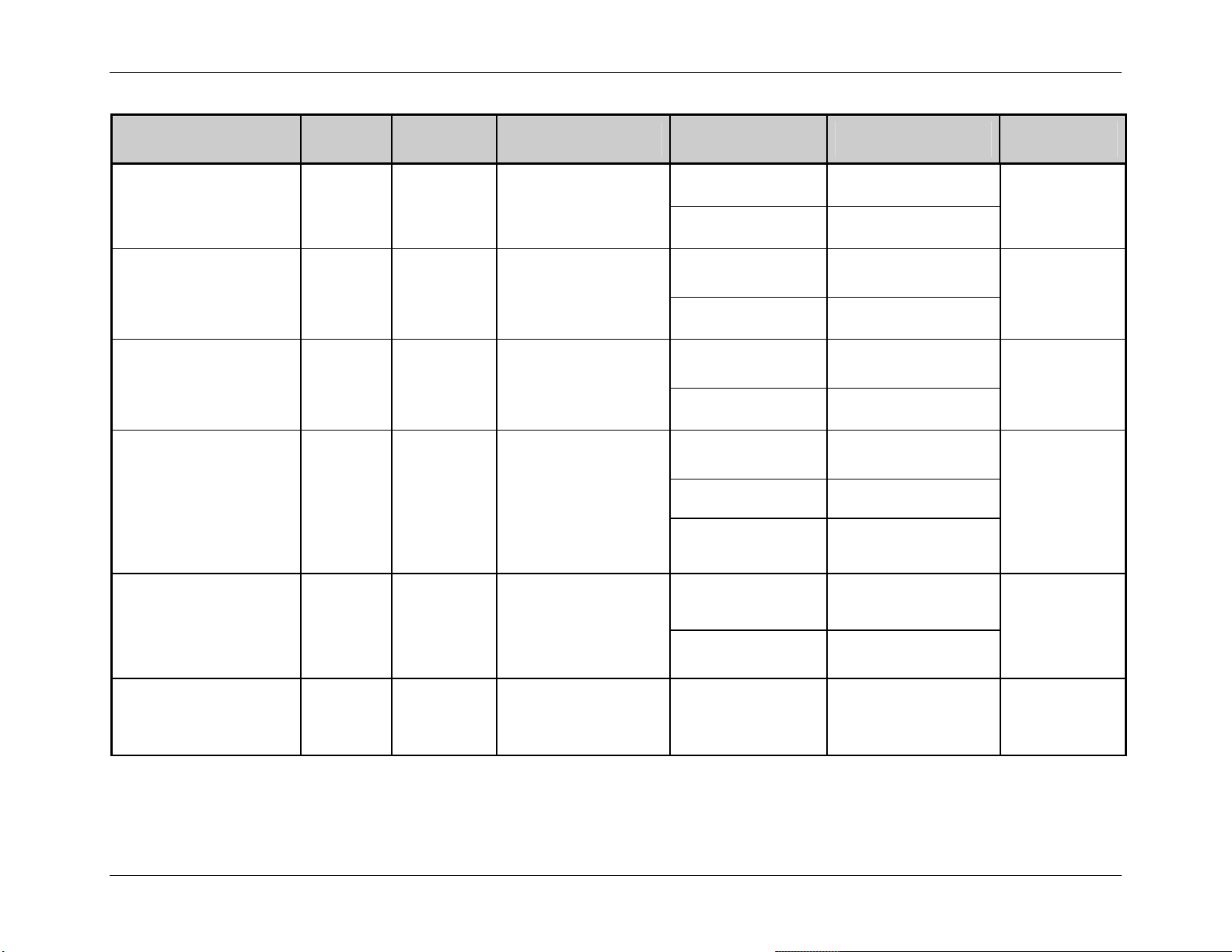
<STX>Kc
Parameter Name
Parameter
Pneumonic
Value /
Range
Extended System-Level Command Functions
Units /
Interpretation
Applicable
Printer Type
Menu Item Equivalent
or Menu Item Number
Command
Equivalent
Format Attributes
Gain Reflective Value
Gap / Mark Value
GPIO Equipped
GPIO Slew
FA
GR
GM
GE
GS
X = XOR,
X, O, T
O = Opaque,
T = Transparent
0 – 255 N/A
0 – 255 N/A
A = Applicator,
A, V, N
V = Verifier,
N = Disabled
0 = Standard,
1 = Low Pulse,
0 – 4
2 = High Pulse,
3 = Active Low,
4 = Active High
Display-Equipped System Settings
EX2 N/A
Display-Equipped Media Settings
EX2 N/A
Display-Equipped Media Settings
EX2 N/A
Display-Equipped Printer Options
Non-Display 25
Non-Display 23
Display-Equipped Printer Options
Non-Display N/A
An
N/A
N/A
N/A
N/A
L = Leftmost dot is zero,
Head Bias
HB
L, R
R = Rightmost dot is
A-Class System Settings N/A
zero
Table 5-1: Configuration Set Commands (continued)
Class Series Programmer’s Manual 48
Page 63

<STX>Kc
Parameter Name
Parameter
Pneumonic
Value /
Range
Extended System-Level Command Functions
Units /
Interpretation
Applicable
Printer Type
Menu Item Equivalent
or Menu Item Number
Command
Equivalent
Head Cleaning
Heat
Host Timeout
Ignore Control Codes
Ignore Distances
HC
HE
HT
IC
IE
0 – 9999
Inches (or centimeters)
multiplied by 1000
0 – 30 N/A
1 – 60 Seconds
Y, N
1, 0
1, 0
Y = Enabled,
N = Disabled
1 = Enabled,
0 = Disabled
1 = Enabled,
0 = Disabled
Display-Equipped Media Settings
N/A
EX2 N/A
Display-Equipped Print Control
Non-Display 23
Hnn
Non-Display 21
Display-Equipped Communications
N/A
EX2 N/A
Display-Equipped Communications
N/A
Non-Display N/A
Non-Display N/A N/A
Display-Equipped System Settings
Imaging Mode
IL
M, S
M = Multiple label,
S = Single label
EX2 N/A
N/A
Non-Display 22
Table 5-1: Configuration Set Commands (continued)
Class Series Programmer’s Manual 49
Page 64
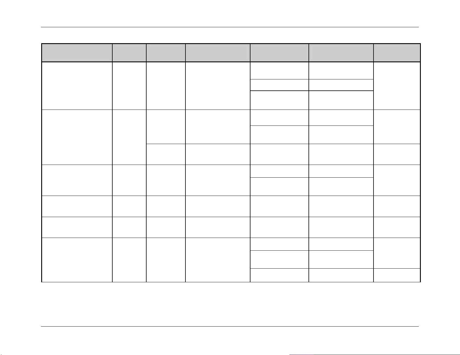
<STX>Kc
Parameter Name
Parameter
Pneumonic
Value /
Range
Extended System-Level Command Functions
Units /
Interpretation
Applicable
Printer Type
Display-Equipped System Settings
Menu Item Equivalent
or Menu Item Number
Command
Equivalent
Input Mode
Internal Module
Label Alignment
Label Rotation
Label Store
Label Width
EM
IM
LA
LR
LM
LW
0, 1
0 = DPL,
1 = Line
Non-Display 21
Non-Display 19
100 – up to
maximum
available, see
Appendix K
0 – 128
Kbytes
4 Kbytes
(0 = disabled)
Display-Equipped System Settings
Non-Display 15
Non-Display 17
Non-Display 18
N, A, Y See Table 5-3.
Non-Display 17
Y, N
F, S
Y = Rotate 180
N = None
F = Fields,
S = States & Fields
Display-Equipped System Settings N/A
Display-Equipped System Settings N/A
Display-Equipped Media Settings
0075 – head
width, see
1/100 inch
Non-Display 13
Appendix K
Non-Display 15
Table 5-1: Configuration Set Commands (continued)
N/A
N/A
<STX>KM
N/A
N/A
<STX>KW
Class Series Programmer’s Manual 50
Page 65

<STX>Kc
Parameter Name
Parameter
Pneumonic
Value /
Range
Extended System-Level Command Functions
Units /
Interpretation
Applicable
Printer Type
Menu Item Equivalent
or Menu Item Number
Command
Equivalent
Language Select
Legacy Emulation
Mark Value
Maximum Length Ignore
Maximum Length
Media Type
LS
LE
MV
SM
ML
MT
String Language Name Display-Equipped System Settings N/A
N, A, P, L
N = None,
A = Allegro,
P = Prodigy,
L = Prodigy Plus,
Display-Equipped System Settings
Non-Display 20
N/A
M = Prodigy Max
N, A, P, L, M
X = XL
Non-Display 22
Display-Equipped Media Settings
0 – 255 N/A
N/A
EX2 N/A
0, 1
0 = Processed normally,
1 = Ignore
Display-Equipped Communications N/A
Display-Equipped Media Settings
0 – 9999 1/100 inch
<STX>M
EX2 N/A
Display-Equipped Media Settings
N/A
<STX>KD
D, T
D = Direct,
T = Thermal Transfer
Non-Display
1
Non-Display
Menu Mode
MM
U, A
U = User,
A = Advanced
Display-Equipped System Settings N/A
Table 5-1: Configuration Set Commands (continued)
Class Series Programmer’s Manual 51
Page 66
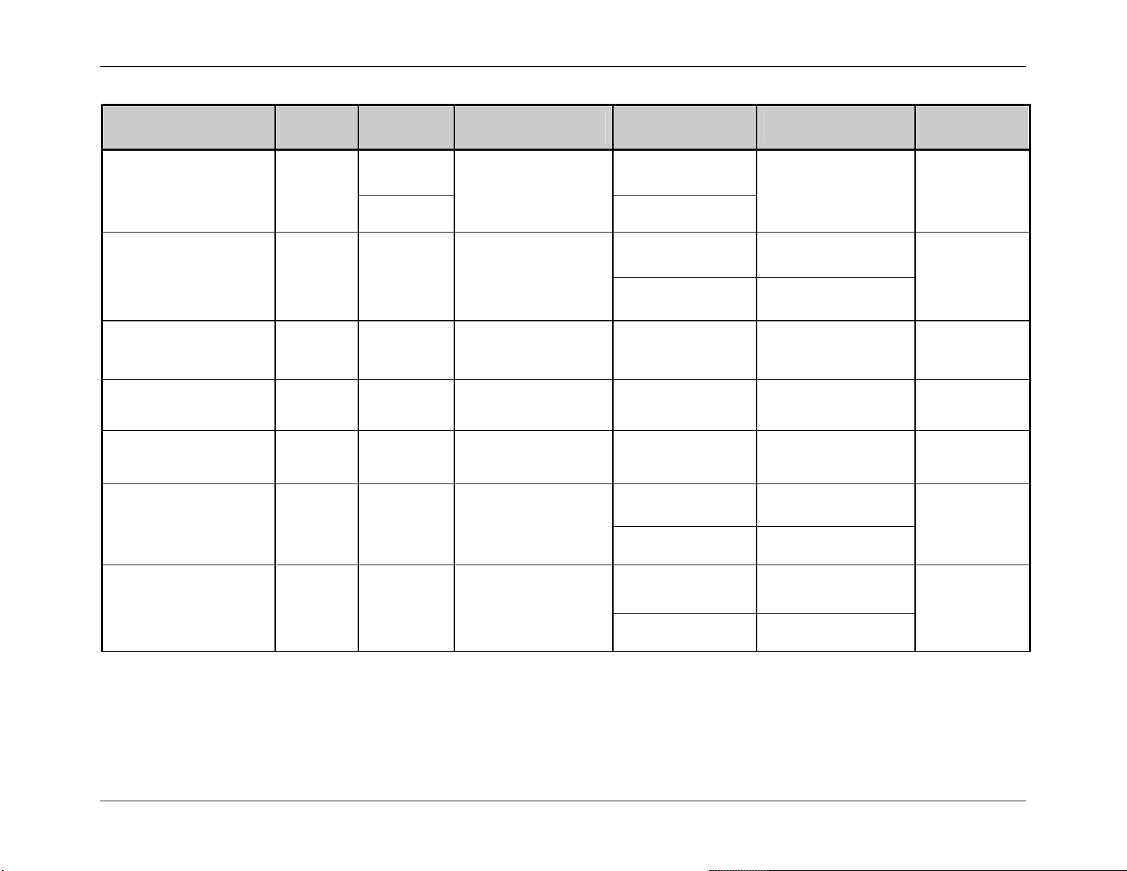
<STX>Kc
Parameter Name
Module Command
Parameter
Pneumonic
MCC
Value /
Range
Extended System-Level Command Functions
Units /
Interpretation
Applicable
Printer Type
Z, G Display-Equipped
See Table 5-4.
B
EX2
Menu Item Equivalent
or Menu Item Number
N/A N/A
Command
Equivalent
Network Setup
No Paper Min
(Out Of Stock)
No Reprint
Option Feedback
Paper Empty
Paper Value
D, G, I, N, P,
NT
S, T, U, w,
See Table 5-5.
W, Y, Z
[2]
TN
NR
OF
0 – 16 .1 Volt DC Non-Display 11 N/A
Y, N
Y = Enabled,
N = Disabled
D, Rx, S See Table 5-6. Display-Equipped Communications N/A
Display-Equipped N/A
N/A
EX2 N/A
Non-Display 26 N/A
Display-Equipped Media Settings
PO
0 – 9999 1/100 inch
N/A
EX2 N/A
Display-Equipped Media Settings
PV
0 – 255 N/A
N/A
EX2 N/A
Table 5-1: Configuration Set Commands (continued)
Class Series Programmer’s Manual 52
Page 67
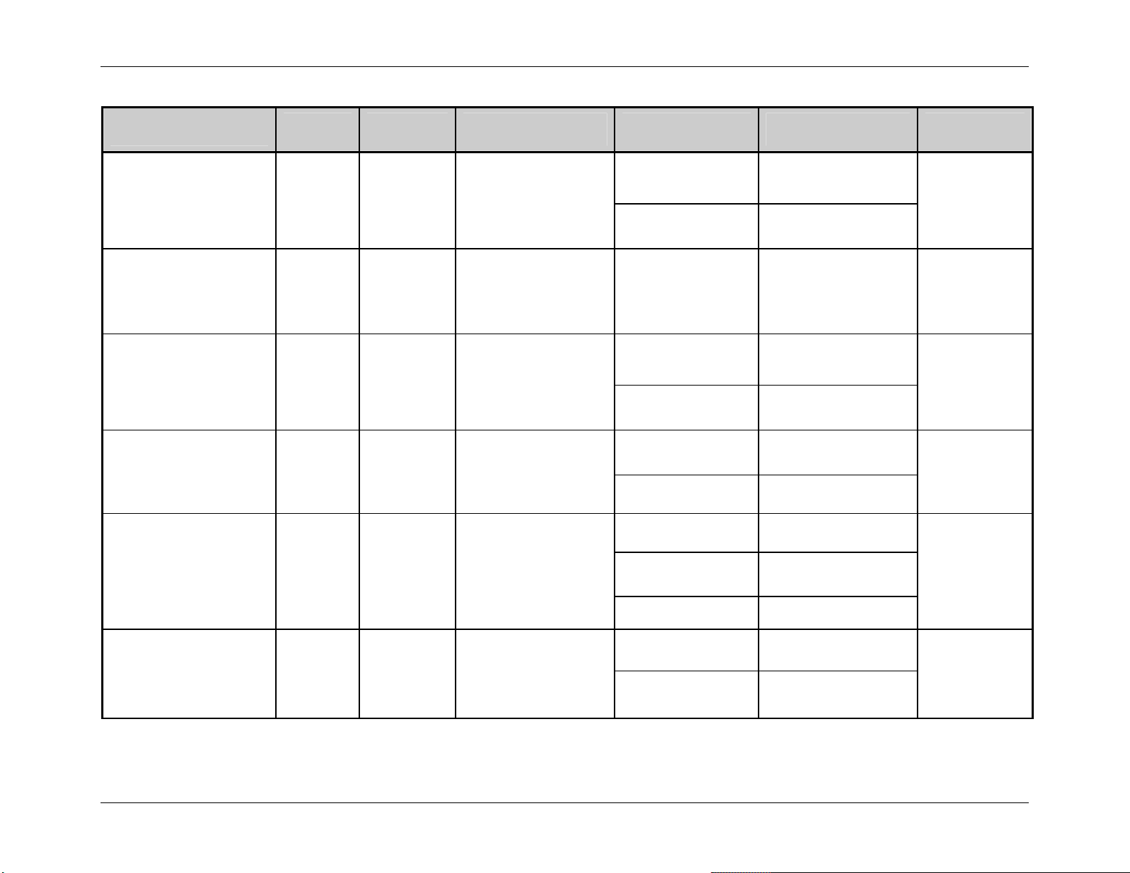
<STX>Kc
Parameter Name
Parallel Direction
Parameter
Pneumonic
PP
Extended System-Level Command Functions
Value /
Range
Units /
Interpretation
xz See Table 5-7.
Applicable
Printer Type
Menu Item Equivalent
or Menu Item Number
Command
Equivalent
Display-Equipped Communications
N/A
EX2 N/A
Password Set
Pause Mode
Peel Mode
Present Adjust
[1]
Present Adjust Fine Tune
PW
PM
PE
PA
PJ
A – Z,
0 – 9
Y, N
Y, N
xxx dots
+ / – dots
Four characters
(or, if security is enabled
then eight characters).
Y = Enabled,
N = Disabled
Y = Enabled,
N = Disabled
Model specific,
see Appendix K;
and, see
Present Adjust Fine
Tune.
Dots (model specific),
see Appendix K.
Display-Equipped System Settings N/A
Display-Equipped System Settings
<STX>J
EX2 N/A
Display-Equipped System Settings
N/A
EX2 N/A
Display-Equipped Print Control
Non-Display 8
N/A
Non-Display 6
Display-Equipped Print Control
N/A
Non-Display 6
Table 5-1: Configuration Set Commands (continued)
Class Series Programmer’s Manual 53
Page 68
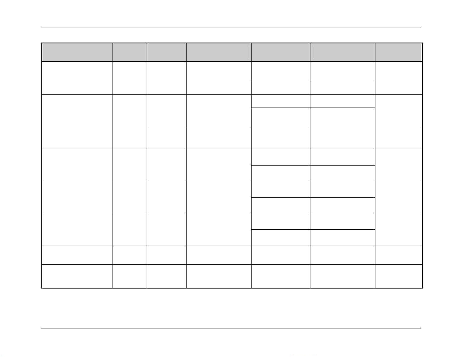
<STX>Kc
Parameter Name
Present Distance
Parameter
Pneumonic
PD
Extended System-Level Command Functions
Value /
Range
Units /
Interpretation
0 – 400 1/100 inch
Applicable
Printer Type
Menu Item Equivalent
or Menu Item Number
Command
Equivalent
Display-Equipped Print Control
<STX>Kf
[4]
N/A
EX2
Present Sensor Equipped
Print Contrast
Printer Level
Print Speed
Query Configuration
PS
PC
PL
pS
QQ
Display-Equipped Printer Options
Non-Display
3
Non-Display
A/Y, E, N/D
A, Y, N
A or Y = Auto,
E = Enabled,
N or D = Disabled
A = Auto,
Y = Enabled,
N = Disabled
Display-Equipped Print Control
0 – 64 N/A
Non-Display N/A
000000 –
FFFFFF
Hex Codes
Display-Equipped System Settings
EX2 N/A
Alpha
character
Model specific ranges;
see Appendix L.
Display-Equipped Print Control
EX2 N/A
Q, K N/A All Configuration Label N/A
<STX>V
<STX>V,
<STX>KD
N/A
N/A
Pa
Reflective No Paper
Minimum (Out Of Stock)
[2]
RN
0 – 16 .1 Volt DC Non-Display 11 N/A
Table 5-1: Configuration Set Commands (continued)
Class Series Programmer’s Manual 54
Page 69
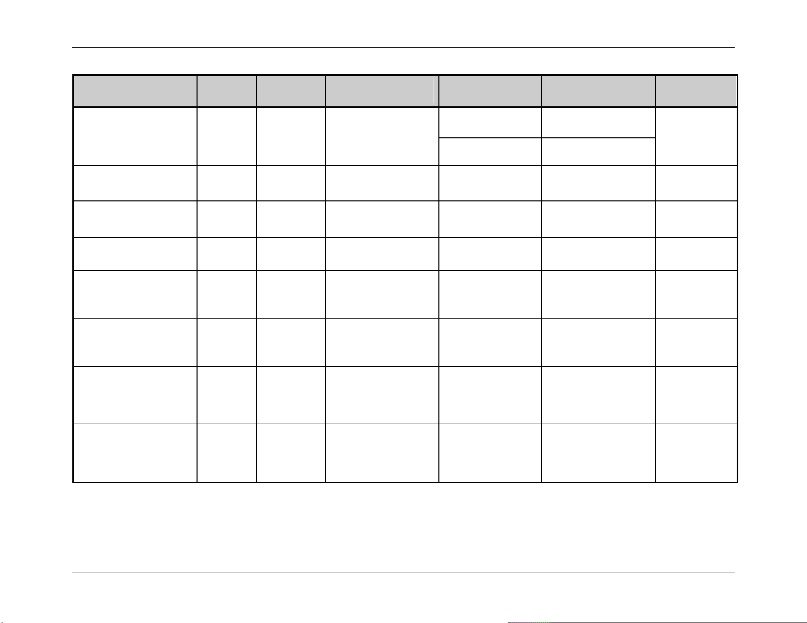
<STX>Kc
Parameter Name
Reflective Paper Value
Parameter
Pneumonic
RV
Extended System-Level Command Functions
Value /
Range
Units /
Interpretation
0 – 255 N/A
Applicable
Printer Type
Menu Item Equivalent
or Menu Item Number
Command
Equivalent
Display-Equipped Media Settings
N/A
EX2 N/A
Reflective TOF Bias
Reflective TOF Delta
Reflective TOF Gain
Retract Delay
Rewinder Equipped
Rewinder Adjust
RFID Configuration
[2]
[2]
[2]
RB
RD
RG
0 – 50 .1 Volt DC
0 – 50 .1 Volt DC
0 – 15 .1 Volt DC
Non-Display
(except EX2)
Non-Display
(except EX2)
Non-Display
(except EX2)
14 N/A
13 N/A
12 N/A
Specified value,
RW
1 – 255
multiplied by ten
Display-Equipped Printer Options N/A
milliseconds
A or Y = Auto,
RM
A/Y, E, N/D
E = Enabled,
Display-Equipped Printer Options N/A
N or D = Disabled
Applied torque, where
RR
-xx, +yy
-30 to +15 is the valid
Display-Equipped Printer Options N/A
range.
M, A, D, S,
RI
L, R, W, E, P,
See Table 5-8. Display-Equipped Printer Options N/A
T, N, U, V
Table 5-1: Configuration Set Commands (continued)
Class Series Programmer’s Manual 55
Page 70
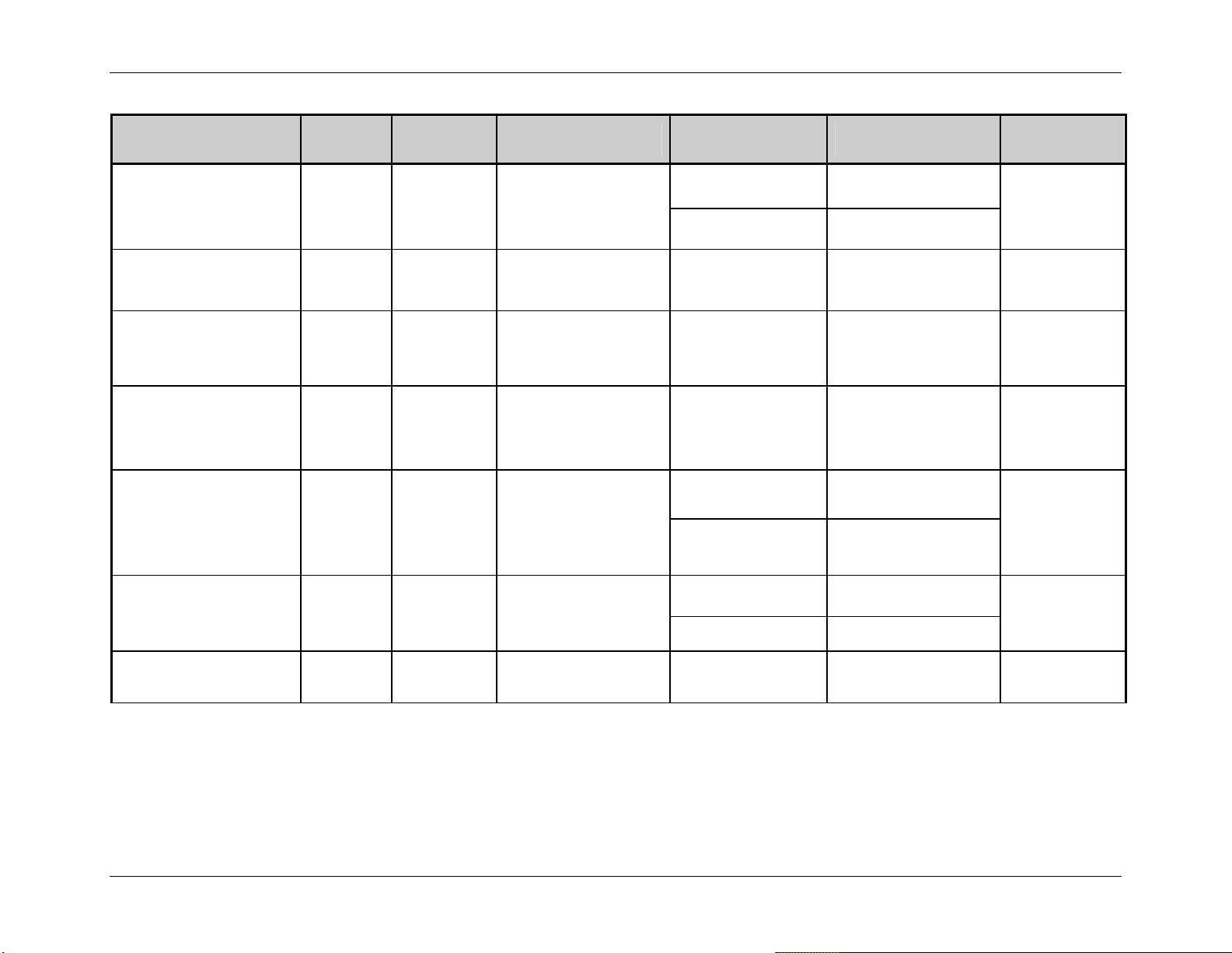
<STX>Kc
Parameter Name
Ribbon Low Diameter
Parameter
Pneumonic
RL
Extended System-Level Command Functions
Value /
Range
Units /
Interpretation
100 – 200 1/100 in.
Applicable
Printer Type
Menu Item Equivalent
or Menu Item Number
Command
Equivalent
Display-Equipped Media Settings
N/A
EX2 N/A
Ribbon Low Pause
Ribbon Low Signal
Ribbon Saver Enable
Row Adjust
[1]
Row Adjust Fine Tune
Row Offset
RP
RS
RE
RA
RF
RO
Y, N
3, 4
Y = Enabled,
N = Disabled
3 = Active Low,
4 = Active High
Display-Equipped Media Settings N/A
Display-Equipped Print Options N/A
A or Y = Auto,
A/Y, E, N/D
E = Enabled,
Display-Equipped Printer Options
N or D = Disabled
xxxx dots
+ / – dots
Model specific, see
Appendix K;
and,
see Row Adjust Fine
Tune
Resolution specific; see
Appendix K.
Display-Equipped Print Control
Non-Display 6
Display-Equipped Printer Control
EX2 N/A
0 – 9999 1/100 in. Display-Equipped Print Control
Table 5-1: Configuration Set Commands (continued)
<STX>R
N/A
N/A
Rnnnn
Class Series Programmer’s Manual 56
Page 71
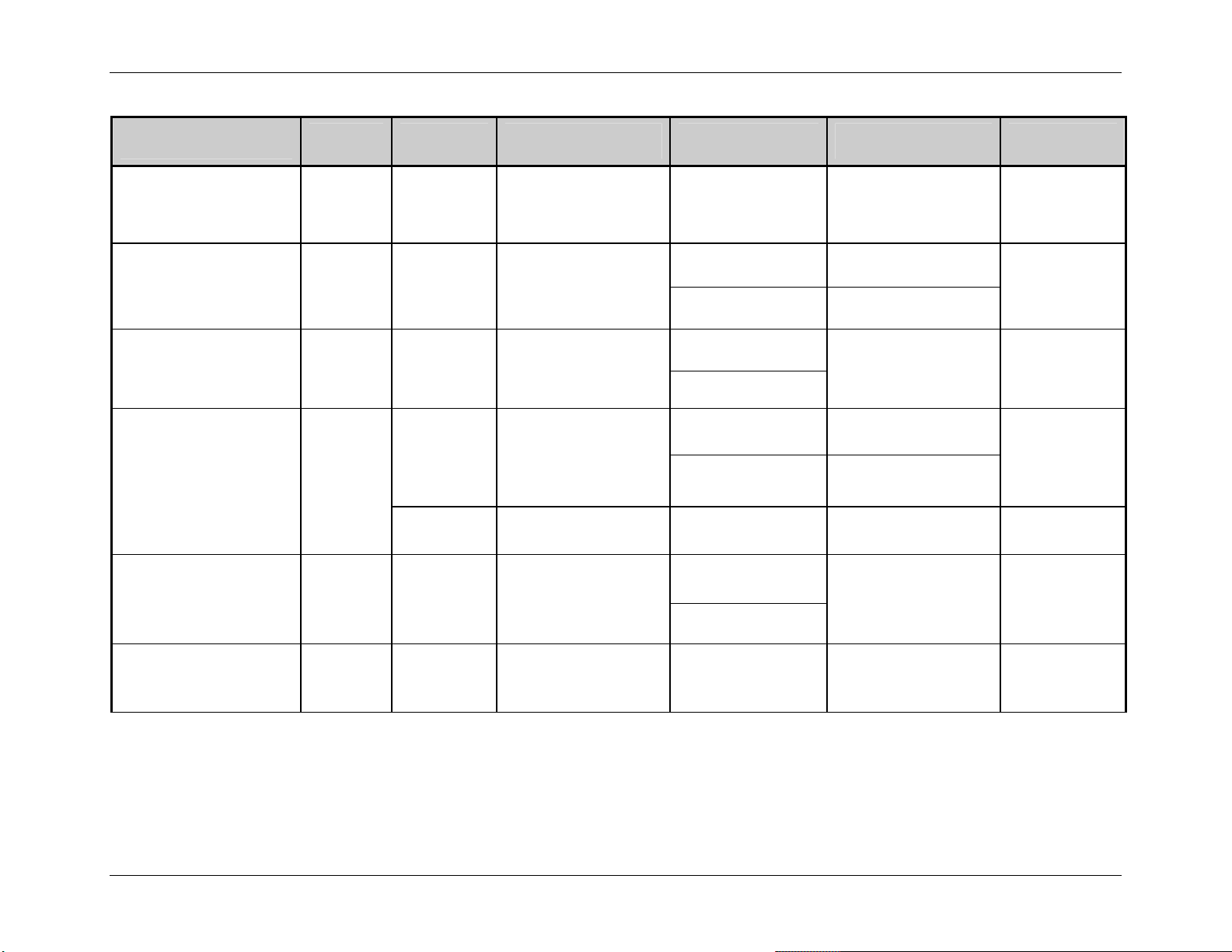
<STX>Kc
Parameter Name
Parameter
Pneumonic
Value /
Range
Extended System-Level Command Functions
Units /
Interpretation
Applicable
Printer Type
Menu Item Equivalent
or Menu Item Number
Command
Equivalent
SOP Adjust
[1]
SOP Emulation
Save As Filename
Scalable Font Cache
Scalable Heap
SA
SE
SF
SC
SH
0 – 255
(128
nominal)
A, L, P, D
Alphanumeric
string
see Row Adjust Fine
N/A,
Tune
A = Allegro,
L = Prodigy Plus,
P = Prodigy,
D = Disable
Up to 16 characters
Non-Display 5
Display-Equipped System Settings
EX2 N/A
Display-Equipped
System Settings N/A
EX2
Display-Equipped System Settings
100 – 8192 Kbytes
Non-Display 14
0 – 128 4 Kbytes (0 = disabled) Non-Display 16
Display-Equipped
0 – 9999 Kbytes
EX2
<STX>O
N/A
N/A
<STX>KS
N/A N/A
Scanner Configuration
SN
C, H, M,
D, B, V
See Table 5-11. Display-Equipped Printer Options N/A
Table 5-1: Configuration Set Commands (continued)
Class Series Programmer’s Manual 57
Page 72
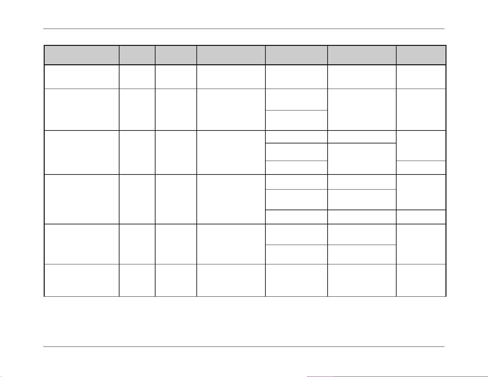
<STX>Kc
Parameter Name
Parameter
Pneumonic
Value /
Range
Extended System-Level Command Functions
Units /
Interpretation
Applicable
Printer Type
Menu Item Equivalent
or Menu Item Number
Command
Equivalent
Security Lock
Sensor Gain Value
Sensor Type
Serial Port
Single Byte Symbol Set
Sl
SG
ST
SP
AS
N, Y, T See Table 5-9. Display-Equipped System Settings N/A
Display-Equipped
0 – 32 N/A
Media Settings N/A
EX2
G, C, R
G = Gap (edge),
C = Continuous,
R = Reflective
Display-Equipped Media Settings
Non-Display
2
Non-Display
<STX>e,
<STX>r,
<STX>c
<STX>KD
Display-Equipped Communications
xyz See Table 5-12.
Non-Display 9 & 10
Non-Display 7 & 8
<STX>KD
Display-Equipped System Settings
2-Byte alpha
character
AA – ZZ, printer
resident symbol set
<STX>y,
Non-Display N/A
N/A
ySxx
Slew Speed
FS
Alpha
character
Model specific ranges;
see Appendix L.
GPIO-Equipped Print Control
<STX>KZSx
Table 5-1: Configuration Set Commands (continued)
Class Series Programmer’s Manual 58
Page 73

<STX>Kc
Parameter Name
Parameter
Pneumonic
Value /
Range
Extended System-Level Command Functions
Units /
Interpretation
Applicable
Printer Type
Menu Item Equivalent
or Menu Item Number
Command
Equivalent
Software Switch
Start of Print
Stop Location
Tear Position
TOF Bias
TOF Delta
TOF Gain
[2]
[2]
[2]
SV
EQ
SL
PT
TB
TD
TG
Y, N
3, 4
Y = Processed
N = Ignored
3 = Active Low,
4 = Active High
Display-Equipped Communications N/A
Display-Equipped Printer Options N/A
Non-Display 20
A, H, P,
C, T, N
Y, N
See Table 5-10.
Y = Enabled,
N = Disabled
Non-Display 16
Non-Display
(except EX2)
20 N/A
N/A
0 – 50 .1 Volt DC Non-Display 14 N/A
0 – 50 .1 Volt DC Non-Display 13 N/A
0 – 15 .1 Volt DC Non-Display 12 N/A
Table 5-1: Configuration Set Commands (continued)
Class Series Programmer’s Manual 59
Page 74

<STX>Kc
Parameter Name
Parameter
Pneumonic
Value /
Range
Extended System-Level Command Functions
Units /
Interpretation
Applicable
Printer Type
Menu Item Equivalent
or Menu Item Number
Command
Equivalent
TOF Precedence
Unit of Measure
User Terminator
Verifier Equipped
Verifier Type
TP
UM
UT
VE
VT
Display-Equipped
N/A N/A
Y, N
Y = Enabled,
N = Disabled
EX2
Display-Equipped
System Settings
M, I
M = Metric,
I = Imperial
EX2
<STX>m,
<STX>n
Non-Display 5
Display-Equipped
ON N/A
N/A N/A
EX2
A or Y = Auto,
A/Y, E, N/D
E = Enabled,
Display-Equipped Printer Options
<STX>KV
N or D = Disabled
A, B, C, D Reserved for future use Display-Equipped N/A N/A
Table 5-1: Configuration Set Commands (continued)
Class Series Programmer’s Manual 60
Page 75
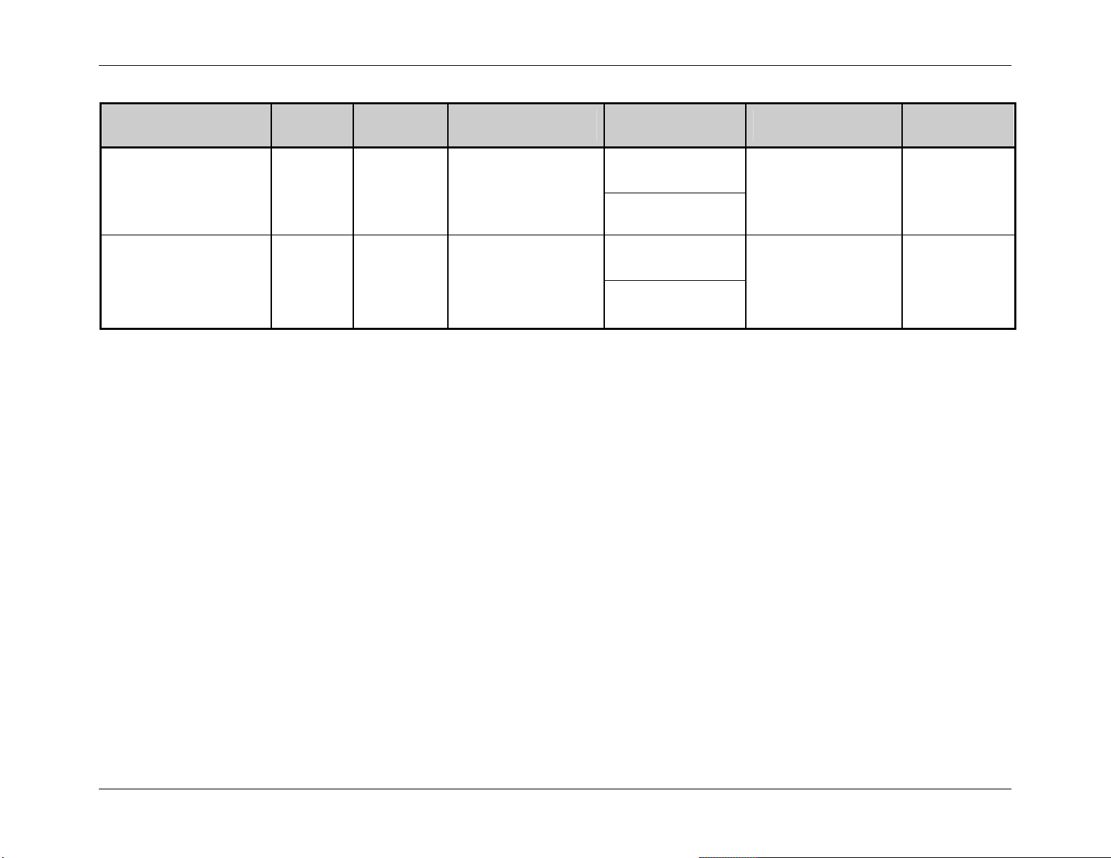
<STX>Kc
Parameter Name
Parameter
Pneumonic
Value /
Range
Extended System-Level Command Functions
Units /
Interpretation
Applicable
Printer Type
Menu Item Equivalent
or Menu Item Number
Command
Equivalent
Display-Equipped
N/A N/A
EX2
WiFi Setup
WE
A, C, F, I, L,
M, N, P, R,
T, V, X
See Table 5-13.
Display-Equipped
WiFi Security
WS
A, K, S, L,
P, U
See Table 5-14.
N/A N/A
EX2
1. Commands are provided for backward compatibility on EX2. The KcQQQ command will respond with the new command equivalent; see associated new commands.
2. The EX2 uses the same Sensor Calibration value setup commands as display model printers.
3. The EX2 will accept Display-Equipped module IDs (D & G) as command parameters for upward compatibility; however, query commands will result in printer responses with
module IDs that are non-display compatible, providing backward compatibility.
4. Present distance changes for EX2 will only be accepted if the Stop Location (SL) is set to “Host.”
Table 5-1: Configuration Set Commands
Class Series Programmer’s Manual 61
Page 76

Extended System-Level Command Functions
<STX>Kc Parameter Overviews
(AL) Alignment Length – This command, critical for small labels when ‘Label Alignment’ is set
to ‘Yes,’ allows a length (measured from leading edge to leading edge of two successive labels)
to be entered. The measured length must be provided to the nearest hundredth of an inch. For
very small labels, errors of 0.01” can result in noticeable print variations on the labels between
the media sensor and the print head. The number of labels that can be fit between the Media
Sensor and the print head will magnify any error in label alignment length. Errors in measurement
are more favorable on the low side rather than the high side.
Non-Display printers only: The printer will verify the label position using the provided
Alignment Length before printing the first label after power-up.
(AS) Single Byte Symbol Set – This command allows for a default single-byte symbol set. See
<STX>y or ySxx for command details.
(BA) Backup After Print – This command determines the timing of the label back up positioning
when the present distance is set and the GPIO option or Present Sensor option (including Peel and
Present) is enabled. When enabled, the printer immediately backs up the label after the applicatorissued start of print signal is received or the label is removed, resulting in faster throughput. If
disabled, the printer will not initiate repositioning until the next label is ready to print (may help
prevent the curling of the label edge).
(BD) Backup Delay – This command sets a time delay for the retraction of a presented label in
one-fiftieth (1/50) of a second increments.
(BL) Backup Label – This command determines the timing of reverse label motion when the I &
W-Class GPIO option is installed and enabled; see Appendix J for signal details.
(BP) British Pound – This command, when enabled, will automatically switch from the Number
symbol (#) found at 0x23 (default PC-850 Multilingual Symbol Set) to the British Pound symbol
(£) at 0x9C.
(BS or bS) Backup Speed – This command controls the rate of label movement during backup
positioning for start of print, cutting or present distance; see Appendix C for available speed
ranges.
Class Series Programmer’s Manual 62
Page 77

Extended System-Level Command Functions
(BZ) Buzzer Enable – This command controls the audible signaling device that acknowledges
User Interface entries and, if enabled, sounds printer warning and fault conditions.
(CA) Column Adjust – This command fine-tunes the Column Offset setting by shifting both the
horizontal start of print position and the Label Width termination point to the right in dots (see
Appendix K) to compensate for slight mechanical differences sometimes evident when multiple
printers share label formats. Note that the
EX2 accepts this command for backward compatibility
only, limited in range (28-228). The <STX>KcQQQ response will show the Column Adjust Fine
Tune (CF) equivalent value.
(CB) Cut Behind – This command allows the printer to queue a specified number of small labels
before a cut is performed to increase throughput.
(CC) Control Codes – This command, depending upon printer type, allows a change to the prefix
of the software commands interpreted by the printer:
Value Units /
Interpretation
S Standard Codes
Hex 01 = SOH command; Hex 02 = STX command; count-by = ^;
Hex 1B = ESC; Hex 0x0D = Carriage Return
Control Code Definition
1 Alternate Codes
2 Alternate Codes 2
Hex 5E = SOH command; Hex 7E = STX command; count-by = @;
Hex 1B = ESC; Hex 0x0D = Carriage Return
Hex 5E = SOH command; Hex 7E = STX command; count-by = @;
Hex 1B = ESC; Hex 0x7C = Carriage Return
(CE) Cutter Equipped – This command allows the printer to sense the cutter option. ‘A’ automatically senses device presence; if undetected, no error is generated. ‘E’ - enables the device,
where its presence must be detected; otherwise, a fault is generated. ‘N’ - disables device
detection. One of these values is returned in response to <STX>KcQQQ. Note that alternate
values are accepted for backward compatibility as follows: For Display-Equipped models ‘Y’ is
equivalent to ‘A’; and, for Non-Display models ‘Y’ is equivalent to ‘E’.
(CF) Column Adjust Fine Tune – This command fine-tunes the Column Offset setting by
shifting both the horizontal start of print position and the Label Width termination point to the
right in dots (see Appendix K) to compensate for slight mechanical differences sometimes
evident when multiple printers share label formats.
Class Series Programmer’s Manual 63
Page 78

Extended System-Level Command Functions
(CH) Communicated Heat Commands – This command causes the printer to ignore DPL Heat
commands; instead, the Heat value is controlled via the menu setting.
(CL) Continuous Label Length – See <STX>c for command details.
(CO) Column Offset – See Cnnnn for command details.
(CS) Communicated Speed Commands – This command causes the printer to ignore DPL speed
commands; instead, speed values are controlled via the menu setting.
(CT) Communicated TOF Commands – This command causes the printer to ignore DPL TOF
(Gap, Continuous, and Reflective) commands; instead, the sensor type is controlled via the menu
setting.
(DE) DPI Emulation – This command allows printers with higher resolutions to emulate lower
print resolutions, as follows:
• 600 DPI can emulate 300 and 203 DPI resolutions
• 400 DPI can emulate a 203 DPI resolution
(DK) Darkness – This command controls the print head strobe timing to fine-tune the HEAT
setting.
(DM) Default Module – See <STX>X for command details.
(DR) Delay Rate – This command sets the number of minutes to delay between multiple batch
printings of Quick Test Labels.
(DS) Double Byte Symbol Set – See <STX>y or ySxx for command details.
Class Series Programmer’s Manual 64
Page 79

Extended System-Level Command Functions
(EM) Input Mode – This command determines the printer’s mode of data processing: Standard
DPL, or Line Mode. In Line Mode the printer will not parse character strings; instead, it will
behave as a line printer, where each carriage return terminated line of data will be printed on the
label according to a stored template. See Appendix S for details.
(EN) End Character – This command terminates a <STX>Kc string.
(EP) End of Print – This command defines the programmable signal output that signifies the End
of Print (EOP) process:
Value
3 Active Low Outputs a logic low (zero) following printing.
Units End of Print Interpretation
4 Active High Outputs a logic high (one) following printing.
1 Low Pulse Outputs a low pulse (approximately 30 milliseconds long) following printing.
2 High Pulse
Outputs a high pulse (approximately 30 milliseconds long) following
printing.
(EQ) Start of Print – This command defines the type of programmable signal input required to
control the Start of Print (SOP) process:
Value Units Start of Print Interpretation
3 Active Low SOP signal must go low for at least 50 milliseconds to initiate printing.
4 Active High SOP signal must go high for at least 50 milliseconds to initiate printing.
(ES) ESC Sequences – This command allows data containing invalid ESC control code
sequences to be processed (helpful because some systems send a “banner” to the printer). When
set to ‘Disabled,’ ESC sequences are ignored and the data is processed. Bitmapped font
downloads are disabled in this mode.
Class Series Programmer’s Manual 65
Page 80

Extended System-Level Command Functions
(ET) Exact Time – This command set the printer to wait until the system is idle before the next
label’s data and time fields are formatted to eliminate any discrepancy between the buffered and
printed times.
(EV) Empty Sensor Level – This command sets threshold value for the ‘Empty’ media sensor
parameter.
(FA) Format Attribute – See the “An” (in Label Formatting Command Functions) command for
details.
(FE) Font Emulation –This command allows font substitution for all Datamax-O’Neil internal
fonts, allowing a new default font to be defined without changing the host DPL data streams.
Selecting a default font that supports a desired character set could match with third party software
to print native characters without modifying the PC drivers. In other words, match the PC font
with the Printer Font then no interpretation would be required by driver or printer. Depending on
host drivers, the user may have to disable Symbol Set commands and modify the Default Symbol
set.
Class Series Programmer’s Manual 66
Page 81
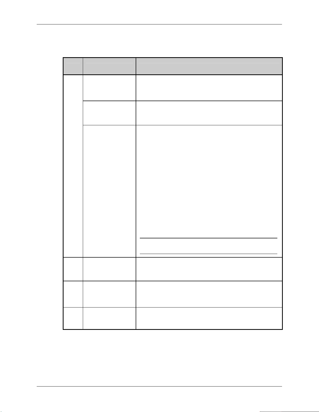
Extended System-Level Command Functions
(FH) Fault Handling – This command determines the level of user intervention and the
disposition of the label being printed when a fault condition (ribbon out, media out, etc.) occurs.
Value Units / Interpretation Selection / Definition
L
Interaction Level,
where:
0 = No Reprint;
1 = Standard;
and,
2 = Void and Retry
In No Reprint Mode (0), printing stops and a fault message is
displayed. After the problem is corrected, the FEED Key must be
pressed to clear the fault. The label in process is not reprinted.
In Standard Mode (1), printing stops and a fault message is
displayed. After the problem is corrected, the FEED Key must be
pressed to clear the fault. The label in process is reprinted.
In Void and Retry Mode (2), depending upon the RETRY COUNT,
one of the following actions when faulted:
• If the Retry Count has not been exceeded, ‘VOID’ is printed on
the label in process and reprinting occurs automatically;
• If the Retry Count has been exceeded, printing stops and a fault
message is displayed. After the problem is corrected, the FEED
Key must be pressed to clear the fault. The label in process is
reprinted; or,
• If the CANCEL Key is pressed, the operator now has the option
of canceling the reprint:
To allow the reprint, press the ESCAPE Key or to cancel the
reprint, press the ENTER Key (the operator now has the option
of canceling the entire label batch by pressing the ENTER Key
again.)
Note: VOID will not be printed when insufficient text space exists (see
VOID DISTANCE, below) or if the fault occurs after the label reaches its
Present Distance at, or above, the TOF).
Sets the distance (.10 - 2.00) to backup the faulted label to print
‘VOID’ on its trailing edge, which also indirectly establishes the
font size of the void message.
D
Void Distance
(.10 - 2.00)
Only used with the RFIF or Scanner option installed and operating.
R
Retry Count
(0 – 3)
Establishes the number of times (0 – 3) the printer will attempt to
reprint a label. If the last label printed in this count has been
voided, the printer will stop and display a fault message.
B
Example: <STX>KcFHD112<CR>
Enable / disable
Y,N
Retract from presented distance prior to feed-clear motion. This
option is intended for use with applicator equipment that may
require certain GPIO signals for proper operation.
Table 5-2: Fault Handling Command
(The example configures the printer to back up and print a one-inch “VOID” message on a
label when a fault is detected; if two successive faults occur during the printing of that label
then the FEED Key must be pressed to clear the fault.)
Class Series Programmer’s Manual 67
Page 82

Extended System-Level Command Functions
(FM) Feedback Mode – See <STX>a for command details.
(FS) Slew Speed – This command controls the rate of label movement between printing areas
when the GPIO port is used; see Appendix L for ranges.
(GE) GPIO Equipped – This command is used to interface the printer to external controlling
devices (see Appendix J):
Value Units / Interpretation GPIO Enable Definition
A Applicator Enables the GPIO for a label applicator.
V Verifier Enables the GPIO for a bar code verifier.
N Disabled Disables the GPIO Port.
(GM) Gap / Mark Value – This command sets threshold value for the media sensor’s ‘gap /
mark’ parameter.
(GR) Gain Reflective Value – This command sets the sensitivity of the reflective media sensor.
(GS) GPIO Slew – This command sets the GPIO slew function and control:
Value Slew Interpretation
0 Standard (Active Low)
1 Low Pulse *
2 High Pulse *
3 Slews while low (Active Low)
4 Slews while high (Active High)
* Pulse must be at least 60 milliseconds in length. Functions as if pressing the Feed Key, clearing
alarms and advancing media.
Class Series Programmer’s Manual 68
Page 83
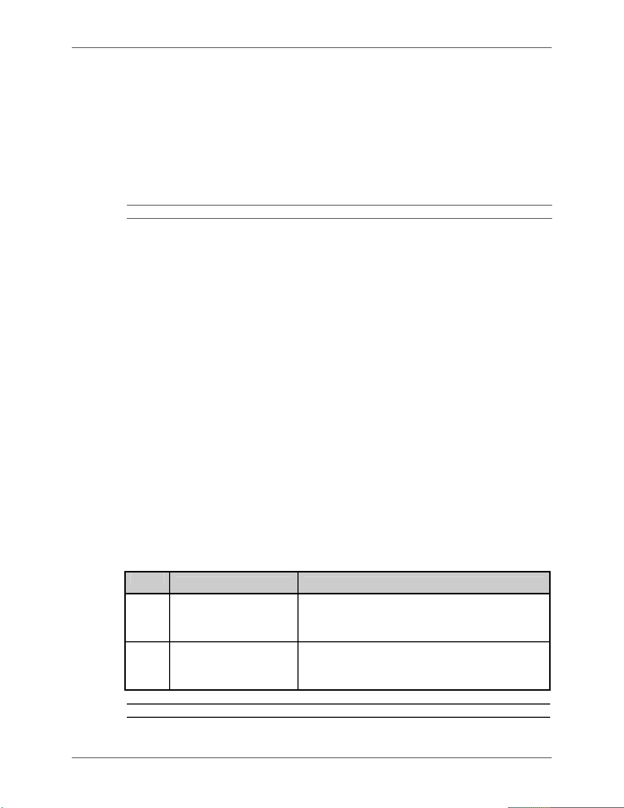
Extended System-Level Command Functions
(HB) Head Bias – This command instructs the printer to switch the dot zero position: as viewed
from the printer’s front panel (or label output side) – when dot zero occupies the left-most
location on the print head then printing is left justified; when dot zero occupies the right-most
location, printing is right justified.
(HC) Head Cleaning – This command controls the print head cleaning routine. The entered value
specifies the inch (or centimeter) count to reach before prompting a print head cleaning. If the
number specified is exceeded three times, the printer will fault until cleaning is initiated.
Note: The number specified is multiplied by one thousand. Zero disables this function.
(HE) Heat – See Hnn for command details.
(HT) Host Timeout – This command controls the number of seconds a communications port must
be idle before the printer may process data from a different port. The value is also used to
“timeout” an image / label format download (i.e., if, at any time, data flow stops before a
complete label format is received, the data will be ignored).
(IC) Ignore Control Codes – This command allows the user to remove control codes (< 20 Hex)
in the data field. The selected line terminator is processed. When enabled, DPL Control Code
(SOH, STX, CR, ESC, and ^) characters are removed from the data string. (Note that some fonts
do have printable characters in this range and they will not be printed when enabled.)
(IE) Ignore Distances – This command, when enabled, prevents <STX>O processing that will
change the start of print position.
(IL) Imaging Mode – This command instructs the printer whether to pre-image the label format:
Value
Units / Interpretation Imaging Mode Definition
The printer images multiple labels as memory permits,
M Multiple Label
achieving the fastest throughput; however, if timestamping, the time will reflect the moment the label is
imaged rather than when actually printed.
The printer images the next label only after the previous
S Single Label
label has been successfully printed. Single processing
provides time-stamps that are more accurate, but it slows
label throughput time.
Note: This selection can affect the accuracy of time-stamped labels and label throughput.
Class Series Programmer’s Manual 69
Page 84
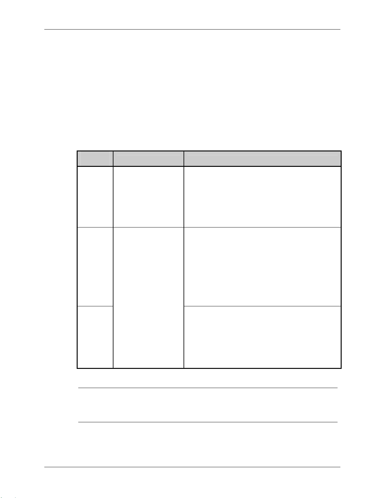
Extended System-Level Command Functions
(IM) Internal Module – This command sets the number of 1K blocks (or 4K blocks for nondisplay models, see the <STX>KM command) allocated for the internal RAM ‘D’ module.
(LA) Label Alignment – This command prevents labels with lengths that are less than the
distance between the print head and the Media Sensor from being wasted at power-up. See the
appropriate Operator’s Manual for specific information. Unless otherwise noted, the following
information pertains to all non-display models:
Value /
Mode
Media Type Description / Operation
N =
Disabled
A =
Auto
Y =
Enabled
6.5-inch and greater (≥
16.51 cm) die-cut,
notched, reflective,
continuous, and multiple
form lengths.
6.5-inch or less (≤16.51
cm) die-cut, notched, and
reflective.
When disabled, non-display printers begin printing at the
current location, unless equipped with RTC (Real Time
Clock); see note below.
The EX2 assumes the label position has not moved while
power was off and that no system changes have occurred.
In auto mode, the printer will verify the label position
using the provided Alignment Length before printing the
first label after power-up.
Press and hold the FEED Key four seconds so the printer
will measure the length of the label.
The EX2 will only measure the label length when new
label stock is loaded.
When enabled, the printer will verify the label position
using the provided Alignment Length before printing the
first label after power-up.
Specify the Label Alignment Length using the
<STX>KcAL command, or the Setup Menu.
Table 5-3: Label Alignment Command
Note: The Real Time Clock (RTC) option allows the position-state of the label to be stored, thus
eliminating the need for an alignment prior to the printing of the first label (assuming the
label position has not moved while AC power was removed). If the label stock has been
changed then a Forced Alignment (press and hold the FEED Key 4 seconds) is
recommended.
Class Series Programmer’s Manual 70
Page 85

Extended System-Level Command Functions
(LE) Legacy Emulation – This command enables the <STX>O and <STX>f print positioning
commands to allow backward compatibility with label formats that were designed for the
Allegro
®
Prodigy®, and Prodigy Plus® (If the printer is display-equipped, also Prodigy Max®
emulation).
(LR) Label Rotation – This command sets label rotation, allowing formats to be flipped 180
degrees.
(LS) Language Select – This command selects the language for the menu system messages and
configuration label. Only languages that are resident will be available.
(LM) Label Store – This command selects the level of stored format recall to include the labelformatting command fields, or the label-formatting command fields and the printer state.
(LW) Label Width – This command sets the maximum limit for the printable width. Objects
extending beyond this limit will NOT print; see Appendix K. (For non-display models also see
the <STX>KW command.)
Note: The EX2 requires this command prior to the start of a label format command (<STX>L).
Class Series Programmer’s Manual 71
Page 86
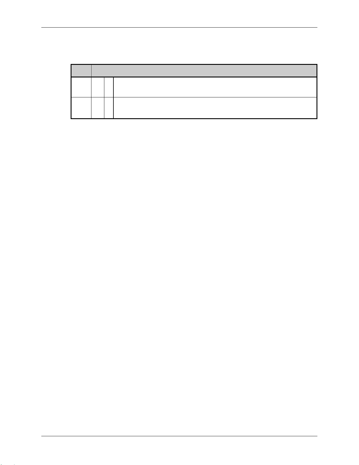
Extended System-Level Command Functions
(MCC) Module Command – This command adjusts the size of Flash module on the optional
Expansion Card according to the table below (see Appendix K for appropriate module details):
Value Module Command Units / Interpretation
Zxx xx
Gxx xx
Size: 1 – 7 Mbytes. This is the amount to be allocated to Module
=
memory will be allocated to Module
Size: 1 – 56, in 128 Kbytes blocks. This is the amount to be allocated to Module
=
any remaining memory will be allocated to Module
F.
X.
Z; any remaining
G;
Table 5-4: Module Command
(ML) Maximum (Label) Length – See <STX>M for command details.
(MM) Menu Mode – This command sets the menu access level of the printer – where User is a
basic listing of menu settings and controls, and Advanced is a full menu listing.
(MT) Media Type – This command selects the printing method: Direct Thermal for use with heat
sensitive media or Thermal Transfer for use with media requiring a ribbon to create an image.
(For non-display models also see the <STX>KD command.)
(MV) Mark Value – This command sets threshold value for the reflective media sensor’s ‘mark’
parameter.
Class Series Programmer’s Manual 72
Page 87

Extended System-Level Command Functions
(NT) Network Setup – This command configures the printer for an Ethernet connection. Each
octet must be zero-filled to be properly interpreted (e.g., an IP Address of 10.12.0.243 must be
sent to the printer as 010.012.000.243).
Value Parameter Interpretation Default Value*
Is Discovery (DHCP or Bootp), where a:
D a
G yyy.yyy.yyy.yyy
I xxx.xxx.xxx.xxx
N xxx.xxx.xxx.xxx
P xxxx
Y = Enable
N = Disable
Is the Gateway Address, where:
y = 0 to 9
Is the IP Address, where:
x = 0 to 9
Is the SNMP Trap Address, where:
x = 0 to 9
Is the Port number, where:
x = 0 to 9
Y
000.000.000.000
192.168.010.026
000.000.000.000
9100
Is the Subnet Mask, where:
S yyy.yyy.yyy.yyy
y = 0 to 9
Is SNMP enable,
where a:
T a
Y = Enable
N = Disable
Is the WINS2 Address, where:
U xxx.xxx.xxx.xxx
x = 0 to 9
Is WiFi enable, where a:
w a
Y = Enable
N = Disable
Is the WINS1 Address, where:
W xxx.xxx.xxx.xxx
x = 0 to 9
Is the DNS1 Address, where:
Y xxx.xxx.xxx.xxx
x = 0 to 9
Is the DNS2 Address, where:
Z xxx.xxx.xxx.xxx
x = 0 to 9
255.255.255.000
Y
000.000.000.000
N
000.000.000.000
000.000.000.000
000.000.000.000
* Prior to the introduction of WiFi, 192.0.0.192 was the IP default value and the Subnet Mask was 0.0.0.0.
Table 5-5: Network Setup
Class Series Programmer’s Manual 73
Page 88

Extended System-Level Command Functions
Example:
<STX>KcNTI010.012.000.243;NTS255.255.000.000;NTG010.012.254.254;NTDN;
<CR>
The command string above is typical of a network setup string (where the values meanings are
shown in the following table). This configuration setup command string may be included with
any other Kc sub-commands.
Sub-commands and Values Interpretation
NTI010.012.000.243
NTS255.255.000.000
NTG010.012.254.254
NTDN
IP Address: 10.12.0.243
Subnet Mask: 255.255.0.0
Gateway Address: 10.12.254.254
DHCP is disabled
(NR) No Reprint – This command controls the label reprint function following the correction of a
fault condition. Upon detection of a fault (ribbon out, paper out, etc.), printing stops and a fault
indicator is illuminated. After the problem is corrected, the FEED Key must be pressed to clear
the fault and resume normal operation. When enabled, the label in process is not reprinted.
(NS) Disable Symbol Set Selection – This command prevents the <STX>y and y commands
from changing the default single-byte symbol set. When enabled, DPL Symbol Set commands are
ignored.
Note: When enabled, the only way to change the current symbol set is with the <STX>KcAS
command.
Class Series Programmer’s Manual 74
Page 89
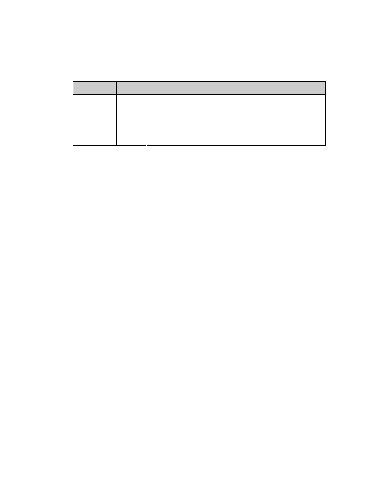
Extended System-Level Command Functions
(OF) Option Feedback Mode – This command configures the printer to output the status of the
RFID or Scanner option to the active port, as follows.
Note: 10.xx firmware is required; and, not supported on the I-4208 printer.
Value Option Feedback Mode Units / Interpretation
D
= Disable
D, Rx, S
Rx
S
RFID Enable, where x is the response format, as follows:
=
A = ASCII
H = Hexadecimal
= Scanner Enable
Table 5-6: Option Feedback Command
Once enabled, the printer will report information about the results of the last label printed. One
response per label is returned to the host (this includes each voided and retried label). The
format and contents of the returned information is as follows:
Printer response format:
<A;B;C;D;E;F>[CR]
Where:
A
- Device type:
R = RFID
S = Scanner
B
- Resulting status:
C = entire label complete
F = faulted (failed) label
U = unknown
C
- The number of expected reads for bar codes or tags, given in
two characters.
D
- The number of good reads for bar codes or tags, given in two
characters.
E
- The printer’s internal Job Identifier and Sub Job Identifier,
given in four characters each.
F
- The data read, delimited with semicolons (;) if multiple reads.
RFID response sample differences: Since RFID commands vary in operation, the data returned
also differs. Write commands return entire tag data; Write/Verify commands return the data
written; and, Read commands return data and length requested in the specified format. (See
Appendix T for a listing of commands.)
Write response example:
<R;C;00;00;0013:0001>[CR]
Class Series Programmer’s Manual 75
Page 90

Extended System-Level Command Functions
Write/Verify hexadecimal response example:
<R;C;01;01;0012:0001;446174616D61782077726974657320524649442062657374>[CR]
Read hexadecimal response example:
<R;C;01;01;0013:0001;446174616D61782077726974657320524649442062657374>[CR]
Write/Verify ASCII response example:
<R;C;01;01;0012:0001; Datamax writes RFID best >[CR]
Read ASCII response example:
<R;C;01;01;0013:0001; Datamax writes RFID best >[CR]
Scanner response samples:
A successfully read label example:
<S;C;03;03;0002:0001;DATA1;DATA2;DATA3>[CR]
A failed label, successfully retried:
<S;F;02;01;0002:0001;DATA1>[CR]
<S;C;02;02;0002:0001;DATA1;DATA2>[CR]
(PA) Present Adjust – This command fine-tunes the Present Distance setting in dots to
compensate for slight mechanical differences sometimes evident if multiple printers share label
formats. The
228). <STX>KcQQQ response shows the
EX2 accepts this command for backward compatibility only, limited in range (28-
Present Adjust Fine Tune (PJ) equivalent value.
(PC) Print Contrast – This command adjusts the relative print edge (gray) component of the print
quality, which allows fine-tuning for specific media/ribbon mix.
(PD) Present Distance – This command sets the label stop position past the start of print. When
the next label format is received, the printer will automatically backfeed to the start position. If
the present distance is set to zero, the printer will operate without reversing. (See Stop Location,
below).
(PE) Peel Mode – This command, when enabled, specifies that a Feed operation be prevented
when the label is presented and not removed, or if the printer is to wait for the GPIO start of print
signal.
Class Series Programmer’s Manual 76
Page 91
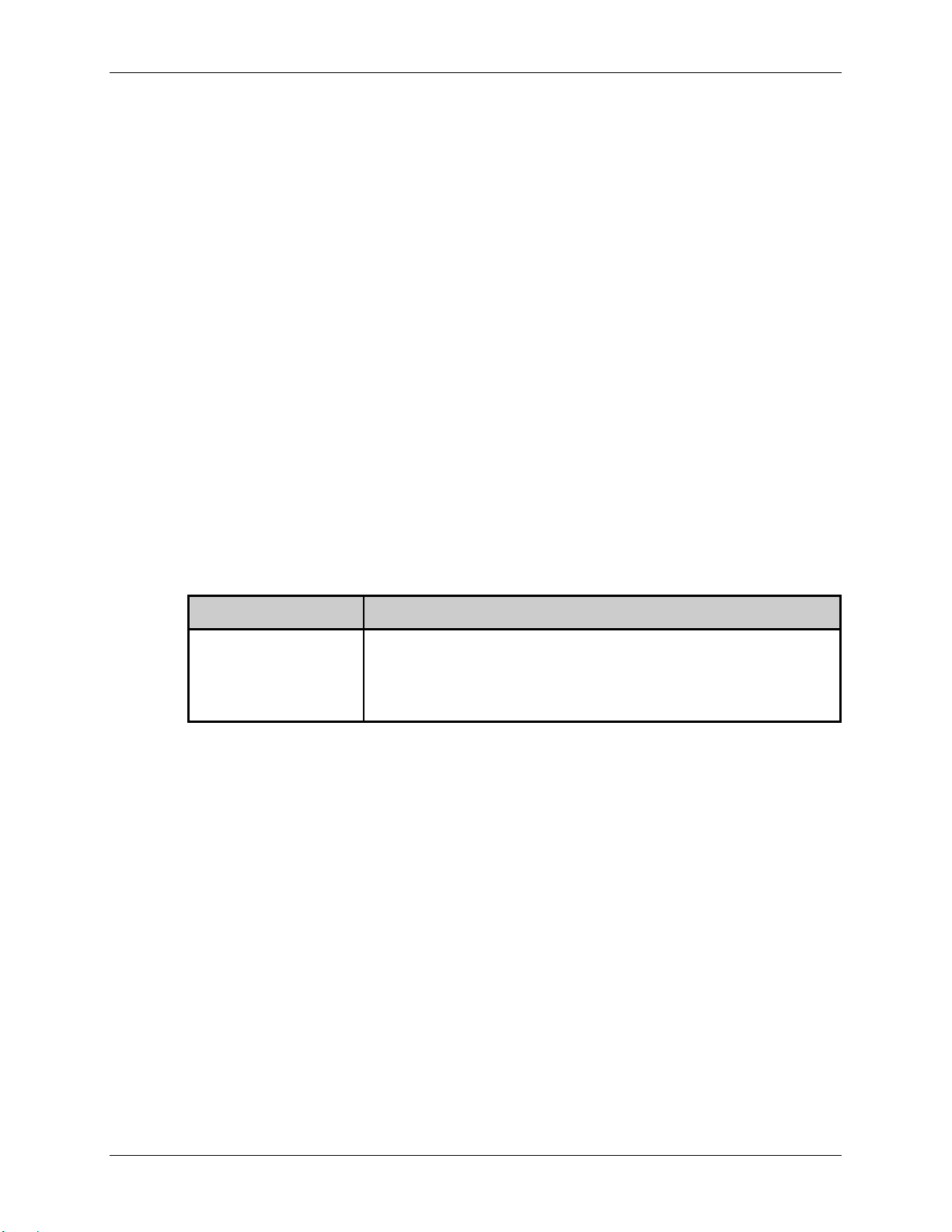
Extended System-Level Command Functions
(PJ) Present Adjust Fine Tune – This command fine-tunes the Present Distance setting in dots to
compensate for slight mechanical differences sometimes evident if multiple printers share label
formats.
(PL) Printer Level – This command is used to upgrade the software feature level of the printer.
(PM) Pause Mode – See <STX>J for command details.
(PO) Paper Empty – This command sets the length of travel before an out of stock condition is
declared.
(PP) Parallel Direction – This command controls the parallel port communications settings:
Value Parallel Direction Units / Interpretation
x = Port ID: A or B
xz
z = Direction: U (unidirectional – one-way communication); or,
B (bi-directional – IEEE 1284 back-channel operation).
Table 5-7: Parallel Communications Configuration Command
(PS) Present Sensor Equipped – This command allows the printer to sense the present sensor
option. A or Y - automatically senses device presence; if undetected, no error will be generated. E
- enables the device, where its presence must be detected; otherwise, a fault is generated. N or D disables device detection. See <STX>V for command details. (Note that the value range for nondisplay printers is only Y, or N. Also see the <STX>KD command.)
(pS) Print Speed – See P (in Label Formatting Command Functions) for command details.
Class Series Programmer’s Manual 77
Page 92

Extended System-Level Command Functions
(PT) Tear Position – This command sets the label stopping location at the tear plate on the
printer’s cover.
Note: Not recommended for use with non-display printers, instead see Stop Location (SL).
(PV) Paper Value – This command sets threshold value for the media sensor’s ‘paper’ parameter.
(PW) Password – This command modifies the numeric password required to access the menu
system when security is enabled. If security is enabled, enter the new password followed by the
old password (with no spaces) in this form: XXXXXXXX
(QQ) Configuration Query – This command requires a parameter of either K or Q. K causes the
printer to respond with the Printer Key, used for generating Upgrade Codes. A parameter value
of Q causes the printer to respond with the current configuration settings. The <STX>Kc
response command stream format is sent to the host computer via the same port as the query
containing all parameters controlled by the <STX>Kc command, and may be used for restoring
the printer’s configuration or for configuring other printers.
(RA) Row Adjust – This command shifts the vertical start of print position (in dots) to fine-tune
the Row Offset setting to compensate for slight mechanical differences sometimes evident if
multiple printers share label formats. Note that the
EX2 accepts this command for backward
compatibility only, limited in range (28-228). <STX>KcQQQ response shows the Row Adjust
Fine Tune (RF) equivalent value.
(RB) Reflective TOF Bias – This command allows the manual entry for the control voltage level
to recognize a label “gap” or “mark.”
Class Series Programmer’s Manual 78
Page 93

Extended System-Level Command Functions
(RD) Reflective TOF Delta – This command allows the manual entry for the control of the low-
level voltage difference level to recognize a label “gap” or “mark.”
(RE) Ribbon Saver Equipped – This command allows the printer to sense the ribbon saver
option. A or Y - automatically senses device presence; if undetected, no error is generated. E enables the device, where its presence must be detected; otherwise, a fault is generated. N or D disables device detection. See <STX>R for command details.
(RF) Row Adjust Fine Tune – This command shifts the vertical start of print position in dots (see
Appendix K) upward or downward to fine-tune the Row Offset setting to compensate for slight
mechanical differences sometimes evident if multiple printers share label formats.
(RG) Reflective TOF Gain – This command allows the manual entry for the control of the
voltage to the LED emitter of the Media Sensor.
Class Series Programmer’s Manual 79
Page 94
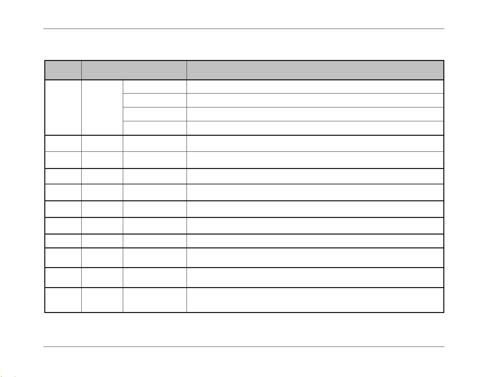
Extended System-Level Command Functions
(RI) RFID Configuration – This command configures the optional RFID interface module, as follows:
Value Units / Interpretation RFID Configuration Definition / Function
D = Disable Disables the RFID module. (“N” is also a valid disabler.)
Mn
AIhh
ALn
DIhh
DLn
Shh
Lhh
Rn
Wn
En
H = HF Enables the RFID module for HF (Securakey).
where n:
U = UHF Enables the RFID module for UHF Class 1 (Alien).
M = UHF Enables the RFID module for UHF Multi-Protocol (Samsys).
where hh: 2-Chararacter Hex ID Sets the Application Family Identifier (AFI), (HF only)
and where n:
E = Enable,
D = Disable
Allows locking the AFI after writing (HF only)
where hh: 2-Chararacter Hex ID Sets the Data Storage Format Identifier (DSFID), (HF only)
and where n:
E = Enable,
D = Disable
Allows locking the DSFID after writing (HF only)
where hh: 2-Chararacter Hex ID Sets the Electronic Article Surveillance (EAS) set, representing the manufacturer’s code. (HF only)
where hh: 2-Chararacter Hex ID Sets the Lock Code (Alien UHF only)
where n: 0 – 9 Sets the number of retries for RFID functions
where n:
where n:
E = Enable,
D = Disable
E = Enable,
D = Disable
Allows locking the tag after writing.
Allows erasures of the tag on error (HF only)
Sets the tag encoding position: A value of 0.00 causes the print position to be used; or, a value
greater than 0 causes the presented position to be used. (Subject to change.)
Pxxx
where xxx: 3-digit value
Table 5-8: RFID Configuration Set Commands
Class Series Programmer’s Manual 80
Page 95

Extended System-Level Command Functions
Value Units / Interpretation RFID Configuration Definition / Function
0 = ISO 15693
1 = Texas Instruments
Tn where n:
2 = Philips
Establishes the tag type (HF only).
3 = ST Micro LRI 512
4 = ST Micro LRI 64
Nn where n:
64 = 64-bit
96 = 96-bit
Sets the UHF tag data size (Samsys UHF only).
0 = EPC 0
1 = EPC 0+ Matrics
2 = EPC 0+ Impinj
3 = EPC 1
Un where n:
4 = ISO 18000-6A
Sets the UHF tag type (Samsys UHF only).
5 = ISO 18000-6B
6 = UCODE EPC 1.19
7 = EM 4022/4222
8 = Gen 2
Vn where n: = a value from -4 to +4 Adjusts the power, in dBmn (Samsys UHF only).
Table 5-8: RFID Configuration Set Commands (continued)
Example:
<STX>KcRIMH;RIA11E;RID22E;RIS04;RIR3;RIWE;RIEE;RIP000<CR>
The above example sets the printer to HF, protect after write AFI 11, protect after write DFSID 22, set EAS Bit (Mfg. Code 0x04), allow 3 tries
for each read or write attempt, lock after writing, erase the tag if there is an error, and use a position of 0.00.
Class Series Programmer’s Manual 81
Page 96

Extended System-Level Command Functions
(RL) Ribbon Low Diameter – This command sets the threshold for a low ribbon indication,
where nnnn is the diameter in hundredths of inches.
(RM) Rewinder Equipped – This command allows the printer to sense the powered internal
rewind option. A or Y - automatically senses device presence; if undetected, no error is generated.
E - enables the device, where its presence must be detected; otherwise, a fault is generated. N or
D - disables device detection.
(RN) Reflective No Paper Minimum – This command sets the media sensor’s reading for the Out
Of Stock (OOS) condition.
(RO) Row Offset – See Rnnnn (in Label Formatting Command Functions) for command details.
(RP) Ribbon Low Pause – This command (when enabled) pauses the printer when a Ribbon Low
Diameter warning is declared; the PAUSE Button must be pressed to continue printing.
(RR) Rewinder Adjust – This command changes the torque applied by the powered rewinder, in
percentage points of the nominal force, to minimize TOF registration drift (sometimes evident
when using small or narrow media).
(RS) Ribbon Low Signal – This command sets the signal output type for the Ribbon Low
Diameter condition when using the optional GPIO (see Appendix J).
(RV) Reflective Paper Value – This command sets the threshold value for the reflective media
sensor’s paper parameter.
(RW) Retract Delay – This command sets a time delay for the retraction of a presented label,
where the time specified is multiplied by ten milliseconds.
Class Series Programmer’s Manual 82
Page 97
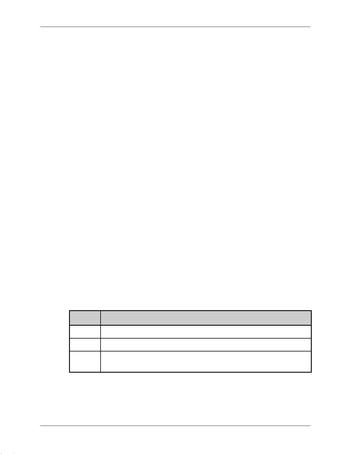
Extended System-Level Command Functions
(SA) SOP Adjust – This command sets the start of print (SOP) location, relative to the top of
form. See <STX>O for command details. The
EX2 accepts this command for backward
compatibility only, limited in range (28-228). The <STX>KcQQQ response shows the Row
Adjust Fine Tune (RF) equivalent value.
(SC) Scalable Cache – This command sets the number of 1K blocks allocated for the scaleable
font engine. Available memory dependent upon model; see Appendix K. (For non-display models
see the <STX>KS command.)
(SE) SOP Emulation – This command enables the <STX>O and <STX>f print positioning
commands to allow backward compatibility with label formats designed for other printers.
(SF) Save As Filename – This command, which may be sent separately or included as the last
command in an <STX>Kc command string, saves the effective printer configuration to a file in
Flash memory with a .dcm file extension.
(SG) Sensor Gain Value – This command sets the control of the voltage to the LED emitter of
the Media Sensor.
(SH) Scalable Heap – This command sets a working “scratch pad space” in DRAM for scalable
font construction.
(Sl) Security Lock – This command provides the ability to password-protect all printer settings
made through the User Interface, as follows:
Value Security Function
Nxxxx
Yxxxx
Txxxx
Where xxxx is the current password, this disables Menu protection.
Where xxxx is a new password, this enables Menu protection and sets a new password.
Where xxxx is a new password, this enables Menu protection, disables the User
Interface Test Button functions, and sets a new password.
Table 5-9: Security Lock Command
Class Series Programmer’s Manual 83
Page 98
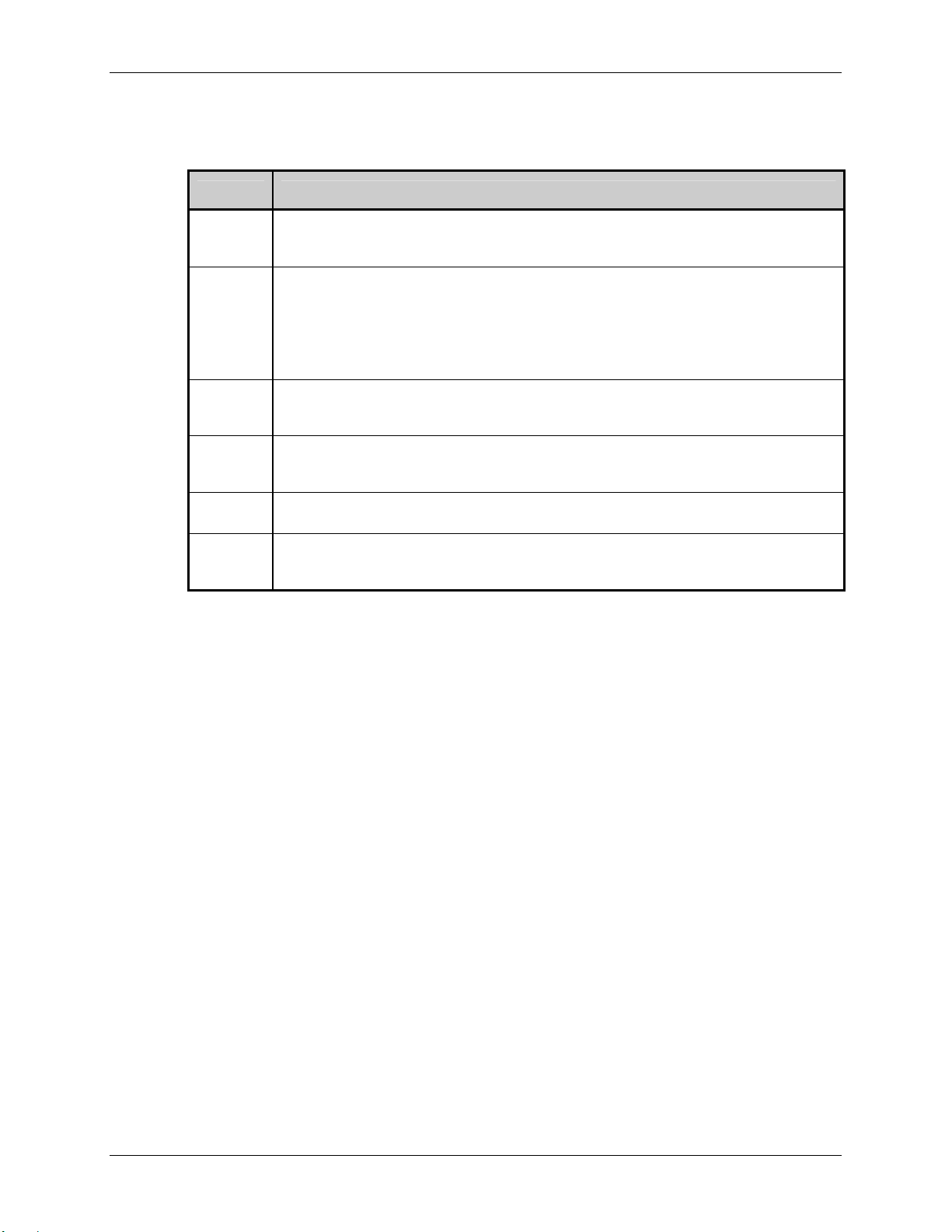
Extended System-Level Command Functions
(SL) Stop Location – This command sets the label stopping (and in certain cases the starting)
location, as follows:
Value Stop Location
A
Automatically sets the stop location. Installed options will be ‘auto-sensed’ and the
appropriate stop position will automatically be set. Host commands are ignored.
Sets stop position according to options installed. If no options are installed the printer
sets stop location to the next label’s start of print. Host commands will override. The
H
stop location (present distance) may be controlled dynamically by the host using the
<STX>f or <STX>Kf commands. This selection has the same effect as <STX>KD
Ignore Host Distance bit value 0.
P
C
T
N
Sets the stop location to approximately 2 mm behind the peel bar edge, a nominal peel
position. The Present Sensor status and this setting are independent.
Sets the stop location to a nominal cut position. For die-cut media, the position is just
following the end of the label. The cutter status and this setting are independent.
Sets the stop location to that of the tear bar on the printer cover.
Sets the stop location to the start of the next label, equivalent to setting the <STX>KD
Ignore Host Distance bit value 1.
Table 5-10: Stop Location Command
(SM) Maximum (Label) Length Ignore – This command controls recognition of the <STX>M
command.
Class Series Programmer’s Manual 84
Page 99
Extended System-Level Command Functions
(SN) Scanner Configuration – This command configures the optional linear scanner, as follows:
Values Scanner Configuration Range / Interpretation
B
Bar Code Type – Specifies the bar code, using two digits, followed by ‘Y’ (to enable) or
‘N’ (to disable) the code, where:
01 = CODE 39
02 = IATA
03 = CODABAR
04 = INTERLEAVED 2 OF 5
05 = INDUSTRIAL 2 OF 5
06 = CODE 93
07 = CODE 128
08 = MSI/PLESSEY
09 = EAN(13/8)
10 = EAN(13/8)+2
11 = EAN(13/8)+5
12 = UPC(A/E)
13 = UPC(A/E)+2
14 = UPC(A/E)+5
Note: To maximize throughput and decoding integrity enable only those symbologies that will
C
Bar Code Count – Specifies the number of codes to be read, where:
00 – 99 (00 = Auto [variable] mode, counting those codes present)
Note: Do not use Auto Mode with bitmapped codes or codes with certain addendums; see
be read.
Appendix F.
H
M
V
Min Readable Height – Sets the vertical distance of the code that must have identical
reads to pass, where:
1 = 1/16
2 = 2/16
3 = 3/16
4 = 1/4
5 = 1/2
0 = Disabled (defaults to Redundancy Level, 2x)
Note: The specified distance should not exceed 50% of the measured bar code height.
Mode – Enables detection of the scanner by the printer, where:
A = Auto (automatically senses presence); Y is also a valid enabler.
E = Enabled (if presence is not detected a fault is generated).
D = Disabled (the scanner is disabled); (N is also a valid disabler.)
Redundancy Level – An alternative data integrity method, where the selected level sets
the number of consecutive, identical decodes required to pass the bar code. If differing
values are read, the count is restarted.
0 = Auto Mode
1 = read code 1X
2 = read code 2X
3 = read code 3X
4 = read code 4X
5 = read code 5X
Note: Depending upon the print speed, higher levels may cause erroneous failures when
Example: <STX>KcSNC00H4MAB12YV0<CR>
scanning multiple or small bar codes.
Table 5-11: Scanner Configuration Set Command
6 = read code 6X
7 = read code 8X
8 = read code 10X
9 = read code 12X
A = read code 15X
B = read code 20X
C = read code 25X
D = read code 30X
E = read code 35X
F = read code 40X
G = read code 45X
(The above sample sets the printer to sense the scanner automatically, to read a variable
number of UPC bar codes, and to pass only those codes where ¼ inch of the bar code has
identical reads.)
Class Series Programmer’s Manual 85
Page 100
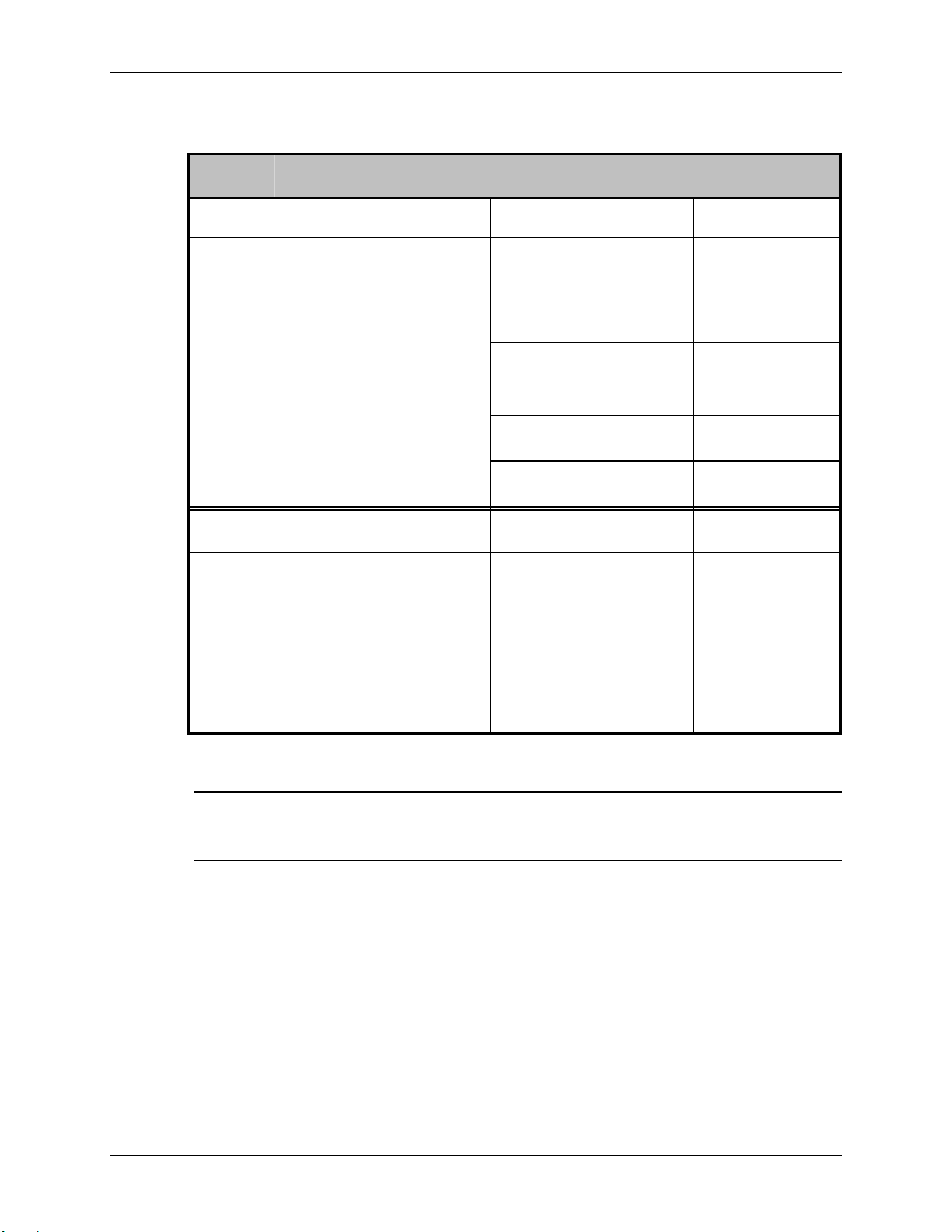
Extended System-Level Command Functions
(SP) Serial Port – This command configures the serial communication port(s) as follows:
Value Serial Port Range / Interpretation
xyz
xyzz
Where: x = Port Identifier: y = Function: z = Setting
A - Serial A
B - Serial B
P - Handshaking Protocol B - both
S - software
H - hardware
N - none
p - Parity N - none
O - odd
E - even
D - Data Length 8 - eight bits
7 - seven bits
S - Stop Bits 1 - one bit
2 - two bits
Where: x = Port Identifier: y = Function: zz = Setting:
A - Serial A
B - Serial B
B - Baud Rate 12 - 1200
24 - 2400
48 - 4800
96 - 9600
19 - 19200
28 - 28800
38 - 38400
Table 5-12: Serial Port Configuration Set Command
Note: For E-Class & M-Class models, this command is followed by the port ID, always ‘A’ (i.e.,
SPA); for EX2 models, the data length, parity, and stop bits are fixed at 8, N, and 1
respectively. And, for Applicator Interface Card-equipped models, this command is also used
to configure the GPIO Auxiliary port (ID always ‘B’).
Example: <STX>KcSPAPB;SPApN;SPAD8;SPAS1;SPAB19<CR>
(The example configures Serial Port A to use hardware and software handshaking, an eight-bit
word, with no parity and one stop bit at 19,200 bits per second.)
(SS or sS) Feed Speed – This command controls the rate of label movement between printing
areas; see Appendix L.
Class Series Programmer’s Manual 86
 Loading...