

Page 1

Workstation Series
User’s Guide
Page 2

Page 3

Copyright Information
CG Triumvirate is a trademark of Agfa Corporation.
CG Times based upon Times New Roman under license from the Monotype Corporation.
Windows is a registered trademark of the Microsoft Corporation.
All other brand and product names are trademarks, service marks, registered trademarks, or registered service marks
of their respective companies.
Limitation of Liability
In no event shall Datamax-O'Neil be liable to the purchaser for any indirect, specia l or consequential damages or lost
profits arising out of or relating to Datamax-O'Neil's products, or the performance or a breach thereof, even if DatamaxO'Neil has been advised of the possibility thereof. Datamax-O'Neil's liability, if any, to the purchaser or to the customer
of the purchaser hereunder shall in no event exceed the total amounts paid to Datamax-O'Neil hereunder by the
purchaser for a defective product.
In no event shall Datamax-O'Neil be liable to the purchaser for any damages resulting from or related to any fai lure or
delay of Datamax-O'Neil in the delivery or installation of the computer hardware, supplies or software or in the
performance of any services.
Some states do not permit the exclusion of incidental or consequential damages, and in those states the foregoing
limitations may not apply. The warranties here give you specific legal rights, and you may have other legal rights which
vary from state to state.
Firmware (Software) Agreement
The enclosed Firmware (Software) resident in the Printer is owned by Licensor or its suppliers and is licensed for used
only on a single printer in the user's Trade or Business. The User agrees not to, and not to authorize or permit any
other person or party to, duplicate or copy the Firmware or the information contained in the non-volatile or
programmable memory. The firmware (Software) is protected by applicable copyright laws and Licensor retains all
rights not expressly granted. In no event will Licensor or its suppliers be liable for any damages or loss, including
direct, incidental, economic, special, or consequential damages, arising out of the use or inability to use the Firmware
(Software).
Information in this document is subject to change without notice and does not represent a commitment on the part of
Datamax-O'Neil Corporation. No part of this manual may be reproduced or transmitted in a ny form or by any means,
for any purpose other than the purchaser's personal use, without the expresse d written permissio n of Datamax-O'Neil
Corporation.
Important Safety Instructions
This printer has been carefully designed to provide many years of safe, rel iable performance. As with all types of
electrical equipment, however, there are a few basic precautions you should take to avoid hurting yourself or damaging
the equipment:
- Carefully read the provided installation and operating instructions.
- Read and follow all warning instruction labels on the printer.
- Place the printer on a flat, firm, solid surface.
- Make sure all openings on the printer remain unblocked; never insert anything into the openings or ventilation slots.
- Do not place the printer near a heat source.
- Do not use your printer near water, or spill liquid into it.
- Be certain that your power source matches a listed voltage rating for the printer (if unsure, check with your dealer or local utility
company).
- Do not place the power cord where it can be stepped on; and, if the power cord becomes damaged, immediately replace it.
- If service is required, use only qualified trained technicians to repair your printer.
All rights reserved. Copyright © 2014, Datamax-O'Neil
Part Number 88-2363-01, Revision C
Workstation Series User’s Guide
Page 4

Workstation Series User’s Guide
Page 5

Agency Compliance
This product complies to the following:
CFR 47 Part 15, Class A Digital Device
This device complies with Part 15, Subpart B of the FCC Rules.
Operation is subject to the following two conditions: 1) This device
may not cause harmful interference, and 2) this device must
accept any interference received, including interference that may
cause undesired operation.
This Class A digital apparatus complies with Industry Canada ICS003 Class A requirements.
UL 60950-1, 2nd Edition. Safety of Information Technology
Equipment Including Electrical Business Equipment
CAN/CSA-C22.2 No.60950-1, 2nd Edition. Safety of Information
Technology Equipment Including Electrical Business Equipment
European Council Directive 2004/108/EC “EMC Directive”
EN55022, Emissions, Class A
EN55024, Immunity
EN61000-3-2, Harmonics
EN61000-3-3, Voltage Fluctuations and Flicker
European Council Directive 2006/95/EC “Low Voltage Directive”
IEC 60950-1, 2nd Edition (CB Scheme)
Directive 2011/65/EU RoHS2 [EN50581(2012)]
Customs Union – Russia, Kazakhstan, Belarus
CISPR 22 Class A Warning
Warning: This is a Class A product. In a domestic environment this
product may cause radio interference in which case the user may
be required to take adequate measures.
Page 6

CoC-MEX
ACMA – Australian Communications and Media Authority
EN55022; 2010 +AC:2011 Class A
Certificate of Compliance - Mexico
CoC-Mex-00588-UL; UL 60950-1, 2nd Edition, 2011-12-19
Page 7

Table of Contents
Agency Compliance .............................................................................................5
1. Safety
Warnings and Cautions ........................................................................................1
General Safety Information ...................................................................................1
2. Overview
Workstation Series Overview .... ...........................................................................3
w1110 Product Tour .....................................................................................................3
Options ..........................................................................................................................6
Standard Features ................................................................................................7
Options .................................................................................................................8
Unpacking the Printer ...........................................................................................8
Checking the Contents .........................................................................................8
Specifications .......................................................................................................9
Print Characteristics ......................................................................................................9
Dimensions and Weight ................................................................................................9
Environmental ...............................................................................................................9
Print Driver Requirements ............................................................................................9
Configuration Utility ...................................................................................................10
3. Connections and Setup
Connections ........................................................................................................11
Power ..........................................................................................................................11
Data .............................................................................................................................11
Media Loading ....................................................................................................12
Media Loading - Peel and Present .....................................................................15
Control Panel ......................................................................................................18
LEDs ...........................................................................................................................18
LED Indicators ............................................................................................................18
Buttons ........................................................................................................................19
Feed .............................................................................................................................19
Test Labels ..................................................................................................................19
Calibration ..........................................................................................................19
Paper Calibration ........................................................................................................19
Sensor Calibration .......................................................................................................20
Printer Settings ...................................................................................................20
Print Driver Installation .......................................................................................21
Overview .....................................................................................................................21
Workstation Series User’s Guide
Page 8

Table of Contents
Important Notes: .........................................................................................................22
4. Operation
Printer Modes .....................................................................................................53
Tear Mode ...................................................................................................................53
Present Sensor Mode ..................................................................................................53
Pause Mode .................................................................................................................53
Reporting ............................................................................................................54
System Report .............................................................................................................54
Settings Report ............................................................................................................55
Webpages ..........................................................................................................56
5. Cleaning and Maintenance
Overview .............................................................................................................57
Intervals ..............................................................................................................57
Supplies ..............................................................................................................57
Cleaning the Top-of-Form Sensor ......................................................................57
Cleaning the Printhead .......................................................................................57
6. Troubleshooting
LED Indicators ....................................................................................................59
Errors ..................................................................................................................59
Warnings ............................................................................................................60
Troubleshooting ..................................................................................................60
Troubleshooting Print Quality .............................................................................61
Tools ...........................................................................................................................61
Preliminary Instructions ..............................................................................................62
7. Appendix A
Symbol Sets .......................................................................................................63
Fonts ...................................................................................................................64
Barcodes ............................................................................................................66
Workstation Series User’s Guide
Page 9
1 Safety
Warnings and Cautions
The following Warnings and Cautions are used throughout this manual:
Warning: W a rnings alert you to possible safety risks.
Caution: Cautions alert you to the potential for equipment damage.
General Safety Information
Caution: This product is intended for indoor use only.
All service procedures should be done by properly trained and qualified service
personnel.
Any on-site assembly required during the installation process must be performed by
properly trained and qualified service personnel.
The product must be connected to a properly grounded and appropriately rated AC
receptacle using the supplied cord set.
Caution: This product contains sensitive electronic components that could be damaged
if exposed to excessive force.
Caution: Use only factory-approved consumables and cleaning kits. Use of any non-
approved supplies could damage the product and void the warranty.
Caution: The printer must be installed on a stable, level surface.
Figure: 1 - 1 Caution - Hot
1 Workstation Series User’s Guide
Page 10

1 | Safety
The printhead heats during printing. Do not touch.
Caution: Serious damage and bodily injury can result if this printer is exposed to liquids
or foreign objects.
Workstation Series User’s Guide 2
Page 11
2Overview
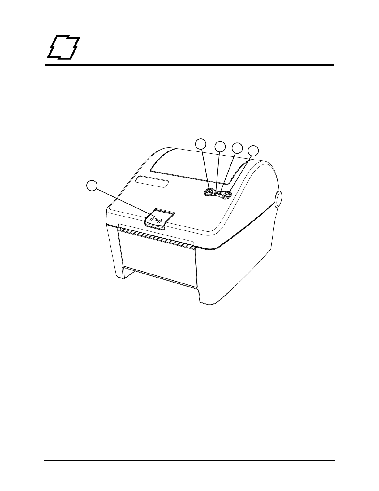
1
2
3
4
5
1. Cover Latch Release
2. Stop/Resume
3. Power LED (Green)
4. Error LED (Red)
5. Feed/Cancel
Workst ation Series Overview
w11 10 Product Tour
The following illustrations show some of the features and available options for the printer.
Figure: 2 - 1 Front View - w1110
3 Workstation Series User’s Guide
Page 12
2 | Overview
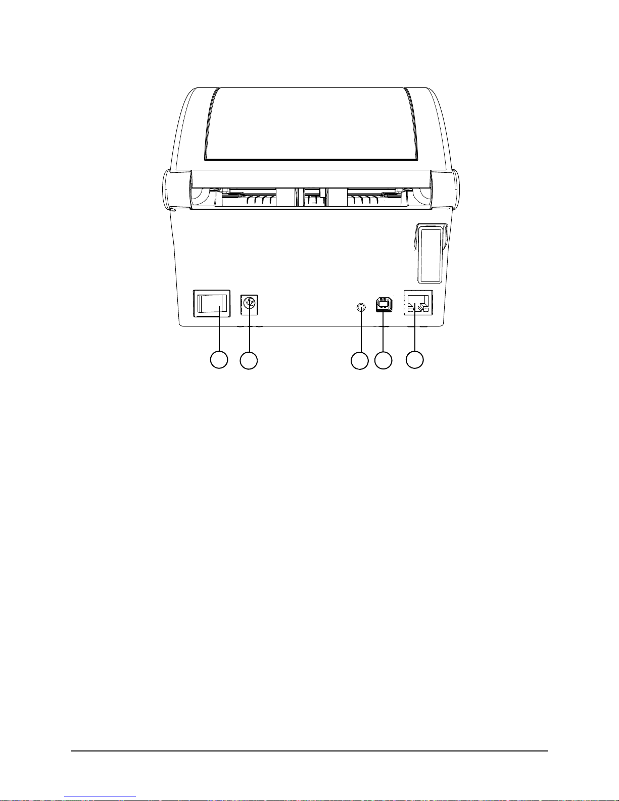
1. Power Switch
2. DC Power Inlet
3. Reset Button
4. USB 2.0 Port
5. Ethernet/Network Port
1
2
3
4
5
Figure: 2 - 2 Rear View - w1110
Workstation Series User’s Guide 4
Page 13
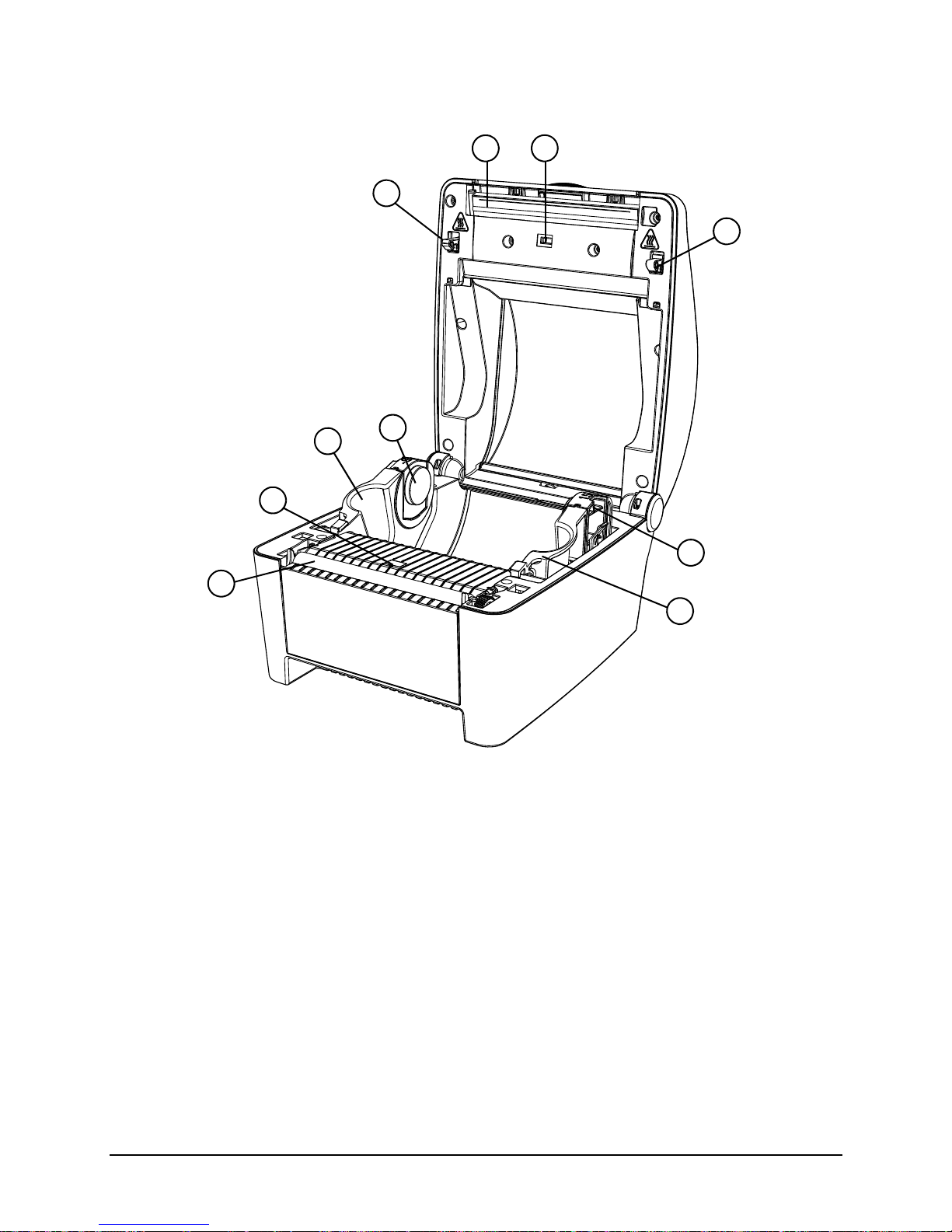
Figure: 2 - 3 Media Area
.
1. Printhead
2. Upper Top-of-Form Sensor
3. Cover Latch
4. Left Media Support Bracket
5. Left Core Adapter
6. Right Core Adapter
7. Right Media Support Bracket
8. Lower Top-of-Form Sensor
9. Platen Roller
1
2
3
4
5
6
7
8
9
3
Overview | 2
5 Workstation Series User’s Guide
Page 14
2 | Overview
1
2
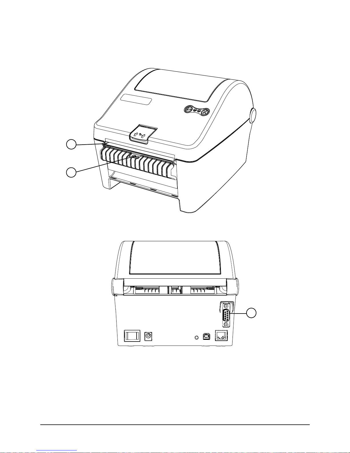
1. Peel Bar
2. Present Sensor
1
1. Serial Interface
Options
Figure: 2 - 4 Peel and Present
Figure: 2 - 5 Serial Interface
Workstation Series User’s Guide 6
Page 15

Standard Features
The thermal printer has the following standard features:
Table 1: Standard Features
Features Descriptions
Max Print Speed 4 IPS / 102 mmps
Resolution 300 dpi / 11.8 dpmm
Memory 32 MB Flash (4 MB User Space) / 64 MB DDR2 RAM
Printer Type Direct Thermal
Media Supply • Roll-fed
• Die-cut
• Continuous Labels: [5” (127 mm) roll max diameter on 1.0” and
1.5” (25.4 mm and 38 mm) core]
Overview | 2
Double-sided Top-of-Form
Sensor
Tear Bar Bar for tearing off gapped or continuous media
Media Back Feed Capable of backing up; max 0.5”
Control Panel Two buttons
Reset Button Inset on the rear of the unit
LEDs Two LEDs: Green - Power On, Red - Error
Power Switch Positioned on the rear of the un it
Chassis / Media Cover Plastic construction with a clear window
Bar Codes See Appendix A
Fonts See Appendix A
Downloadable Font Types • True-Type Scalable
Graphics Full support of PCL5e and GL/2 graphics capability.
Fixed position for center-biased stock:
• Label Gap
• Reflective black mark on the bottom or the top of the form
• PCL Bitmap (300 dpi)
[Support for various host-based file formats (PCX, BMP) are not part of
the PCL5e standard but are supported and converted by standard
applications]
Industry Standard Printer
Language
Interfaces • USB 2.0 Device
HP PJL, HP PCL5e, HP GL/2 and HP XL, printer languages with autolanguage select and extensions for barcode capabilities. Bi-directional
communications capability is also supported.
• LAN 10/100
7 Workstation Series User’s Guide
Page 16

2 | Overview
Features Descriptions
Printer Driver Supported
Operating Systems
Operating Temperature 32°F (0°C) to 104°F (40°C)
• Windows XP
• Windows Vista
• Windows 7
• Windows 8
Options
The following options are available:
• Peel and Present
• Serial Interface
• Non-US Power Cords
Unpacking the Printer
Upon receiving the printer, verify the box is undamaged. Carefully unpack the printer
from its packaging and visually check for any physical damage that may have occurred
during shipment.
Checking the Contents
The contents may vary depending on your configuration. It is recommended that all
packaging materials be saved if the printer is to be shipped again. If the packaging
material is discarded, new packaging material may be available from your reseller.
• Printer
• Power Cord
• AC Adapter
• Driver CD
• Product documentation
• Accessories/Options
Additional items that may be required include the following:
• All Applicable Communication Cables
•Media
Workstation Series User’s Guide 8
Page 17

Specifications
Print Characteristics
Table 2: Print Characteristics
Variable Specifications
Print Resolution 300 dpi (11.8 dpmm)
Max Print Width 4.16” (105.7 mm)
Max Print Speed 4 ips (102 mmps)
Max Feed Speed 4 ips (102 mmps)
Max Back-up Speed 4 ips (102 mmps)
Media Width Range* 0.75” - 4.33” (19 mm - 110 mm)
Media Thickness Range* 0.003” - 0.008” (0.076 mm - 0.20 mm)
Print Length Range 0.25” - 30” (6.35 mm - 762 mm)
*Media wound out.
Overview | 2
Dimensions and Weight
Table 3: Dimensions and Specifications
Height Width Depth Weight
6.02 in (15.3 cm) 6.75 in (17.1 cm) 8.32 in (21.1 cm) 3.1 lbs. (1.4 kg)
Environmental
Table 4: Temperatures
Temperature Humidity
Operating 32°F to 104°F (0°C to 40°C) <=20% to 80%
Storage -4°F to 140°F (-20°C to 60°C) <=35%
Print Driver Requirements
Table 5: Print Driver Minimum System Requirements
Minimum System Requirements
Processor / Speed 500 MHz processor
RAM 512 MB
Hard Drive Space 6 MB
9 Workstation Series User’s Guide
Page 18

2 | Overview
Minimum System Requirements
Supported Operating Systems Windows XP - x86 & x64
Windows Vista - x86 & x64
Windows 7 - x86 & x64
Windows 8
Configuration Utility
Table 6: Configuration Utility Minimum System Requirements
Minimum System Requirements
Processor / Speed 500 MHz processor
Supported Operating Systems Windows XP - x86 & x64
Windows 7 - x86 & x64
Windows 8
RAM 256 MB
Hard Drive Space 15 MB
Minimum Screen Resolution 800 x 600
.NET Framework 3.5 SP1
Workstation Series User’s Guide 10
Page 19

3 Connections and Setup
Connections
Power
To connect the printer to a viable power source, please follow the steps below.
Caution: Ensure the printer power switch is off before connecting the AC power and
data/network connectivity cables to the printer.
Caution: Adhere to all environmental requirements when installing and using the printer.
Use of the product in an unsuitable environment may affect print quality and the
durability of the printer and may void the manufacturer’s warranty.
1. Place the printer on a suitable level surface capable of securely supporting 8lbs.
2. Connect the AC power cord to the power supply brick
3. Connect the AC power cord from the power supply brick to AC utility power.
4. Connect the DC power cord from the power supply brick to the printer power jack.
5. Using the power switch, turn on the printer.
During power-up, the LEDs indicate the status of the printer.
Table 1: Power-Up - LED Status
Action Green LED Red LED
Printer begins to power-up Solid Solid
Printer indicates powering up Double Blink Double Blink (synchronized
with Green LED)
Printer is online Solid Off or slow blink which
typically indicates cover open
or an uncalibrated condition.*
Data
Printer data connectivity can be accomplished by the following standard or optional
interfaces:
•USB
• Ethernet/Network
• Serial (Optional)
11 Workstation Series User’s Guide
Page 20

3 | Connections and Setup
Connect the appropriate interface cables for your configuration. For network connection,
the default is DCHP.
*Note: To calibrate the printer sensors, remove paper and close the cover, then press
and hold the rear panel reset switch together with both printer buttons simultaneously for
five (5) seconds and release. Now, only the Green LED should remain lit. Rapidly
flashing Red LED indicates sensor is blocked or a hardware problem exists.
Media Loading
The w1110 printer supports either a 1” core or a 1.5” core paper roll. The core adapters
can be removed, rotated and reinstalled depending on the desired core size.
Please consult your reseller to obtain the appropriate media.
1. Lift the cover latch release and open the cover.
2. Verify the core size for the paper roll being used and select the appropriate core
adapter side.
a. To change the core adapter size, gently press the locking tabs outward and
remove the media core adapters from the media support brackets.
Workstation Series User’s Guide 12
Page 21

Connections and Setup | 3
Locking Tabs
1.5” Media
Core Adapter
Note: The media core sizes are printed on the top of the core adapters.
Figure: 3 - 1 Media Core Adapters
b. Reinstall the core adapters with the corresponding number for the appropriate
core size facing upwards.
Note: Ensure the core adapters have snapped into place.
3. Slide the media support brackets outward and place the paper roll between them.
13 Workstation Series User’s Guide
Page 22

3 | Connections and Setup
Note: The paper must be wound out.
Figure: 3 - 2 Paper Roll Installation
4. Release the media support brackets ensuring the core is secured by the core
adapters.
Workstation Series User’s Guide 14
Page 23

5. Route the paper under the support bracket guides.
Left Guide
Right Guide
Figure: 3 - 3 Support Bracket Guides
Connections and Setup | 3
6. Close and latch the printer cover.
7. Feed the paper to find top-of-form.
Note: When installing new media, perform a paper calibration to ensure the printer finds
the top-of-form.
Media Loading - Peel and Present
The peel and present option allows for the media labels to peel at the peel bar while the
label backing routes away from the labels.
15 Workstation Series User’s Guide
Page 24

3 | Connections and Setup
1. Open the peel and present sub-assembly .
a. Rotate the peel and present sub-assembly forward.
Figure: 3 - 4 Peel and Present Assembly
2. Load the media into the support bracket and the core adapters.
3. Remove the enough labels to expose at least 6” of backing. Insert the backing
behind the roller of peel and present sub-assembly until it appears underneath.
Workstation Series User’s Guide 16
Page 25

Connections and Setup | 3
Label Backing
Note: Be sure there are no labels attached to the backing that is routed behind the peel
and present sub-assembly.
Figure: 3 - 5 Media Backing
4. Pull the label backing tight to ensure proper tension of the label backing.
5. Hold the backing tight and close the peel and present sensor assembly.
6. Close and latch the printer cover.
7. Feed the paper to find top-of-form.
Note: Peel and present mode is enabled through the configuration utility. If both peel
and present mode and prompt mode are enabled at the same time, only prompt mode
will be active.
17 Workstation Series User’s Guide
Page 26

3 | Connections and Setup
Control Panel
The control panel consists of the two (2) main buttons on the printer cover, two (2) LEDs
on the printer cover and the reset button on the back of the printer. All three are used to
perform certain printer functions.
LEDs
The green and red LEDs may blink during the operation of the printer. There are
functions of the printer where the blinking lights can be used to interpret the printer’s
state.
A slow blink is considered a repeating blink that lights for 0.8 seconds and then turns
off for 0.8 seconds.
A fast blink is considered a repeating blink that lights for 0.1 seconds and then turns
off for 0.1 seconds.
A Synchronized blink is when both LEDs turn on and off at the same time.
An alternating blink is when green and red LEDs turn on and off opposite of each
other.
A double blink is considered two short blinks with a delay in between.
More information is presented in the troubleshooting section.
LED Indicators
The LEDs are used to indicate the printer’s state.
Table 2: LED Chart
Light Printer State
Green Fast Blink - Waiting for an operator action (to press Resume or to remove label)
Slow Blink - Printer is processing data
Solid Light - Printer ready idle state
Short Blink with Delay - Configuration utility control mode
Red Fast Blink - Hardware error or Sensor blocked during calibration
Slow Blink - Warning
Solid Light - Fault
Fast Blink with Pause - Maintenance timer expired
Workstation Series User’s Guide 18
Page 27

Light Printer State
Connections and Setup | 3
Green/Red
Combination
Fast Alternating Blink - Recovery mode
Slow Alternating Blink - Upgrade in progress
Slow Synchronized Blink - Cooling down or processing with a warning
Synchronized Double Blink - Power-up in progress
Buttons
The operation of the buttons consists of long or short presses depending on the
operation being performed. A button pressed for three (3) or more seconds is considered
a long press. A button pressed for less than three (3) seconds is considered a short
press.
The Stop/Resume button is positioned on the left side of the printer’s control panel and
the Feed/Cancel button is positioned on the right side. Together with the reset button on
the back of the printer, these buttons enable certain printer functions.
Note: Refer to the Operation section of this guide for more information about the
operational functionality of the buttons.
Feed
To position the label to the top-of-form, press the Feed/Cancel (right) button once the
media has been installed.
Test Labels
To print a test label from the printer, push the Stop/Resume button and the Feed/Cancel
button together with a short press. A quality label will print. This function can also be
performed with the configuration utility.
Calibration
The printer uses upper and lower top-of-form sensors to determine top-of-form. Both
sensors are transmissive and reflective to ensure top-of-form for qualified media. There
are two (2) types of calibrations:
• Paper Calibration
• Sensor Calibration
Paper Calibration
The printer should be calibrated after a new type of media has been installed or to verify
a paper out warning. When re-loading the same type of media, calibration should not be
necessary unless the printer does not find top-of-form.
1. Install the paper into the printer .
19 Workstation Series User’s Guide
Page 28

3 | Connections and Setup
2. Close and latch the printer cover.
3. Select the Stop/Resume button and the Feed/Cancel button together with long
presses until the paper begins to move.
Note: The media will advance through the printer verifying the top-of-form.
Sensor Calibration
Sensor calibration is set during the manufacturing process and may only need to be
performed after upgrading the printer’s software or resetting defaults. This is indicated by
the red LED blinking slowly after power-up.
1. Remove the paper from the printer.
2. Close and latch the printer cover.
3. Push the Reset, Stop/Resume, and the Feed/Cancel buttons together with one long
press.
Note: Wait for the green LED to fast blink followed by solid green.
Printer Settings
All printer settings can be adjusted in the configuration utility or the printer’s internal web
pages. Refer to the Help section in the utility for more information.
Workstation Series User’s Guide 20
Page 29

Connections and Setup | 3
Print Driver Installation
Overview
This installation should be executed only on a computer where a pw Series printer driver
is not currently installed or one that the driver have been completely removed.
The Windows driver is located on the Accessories CD-ROM included with the printer . For
the latest version please visit our web site at http://www.datamax-oneil.com
Installing the Windows Driver:
1. Place the Accessories CD-ROM included with the printer into the computers CDROM drive. Once the CD-ROM starts select your printer model then “Install Driver”
from the menu. Follow the instructions on the screen to install.
If the driver was downloaded from our website, simply double click the downloaded
“.exe” file to launch the installation.
2. Check the “Remove printer drivers” radio button then click
‘Next’. If this option is not available skip to Step 6.
3. On the next screen check the “Remove printers” radio
button then click ‘Next’.
4. Browse the list of installed printers, if any “Workstation” or
“Performance” printers are listed check the corresponding
check boxes and click ‘Next’ to remove the installed
printers.
5. The next screen will show a summary of items to be
removed, click ‘Finish’ to complete the removal process.
Once complete return to the main screen to install the new
driver.
21 Workstation Series User’s Guide
Page 30

3 | Connections and Setup
6. Check the “Install printer drivers” radio button then click
‘Next’ and follow the on-screen instructions to install the
driver.
7. When prompted, select your printer from the list, (i.e.,
Datamax-O’Neil w1110). Continue to follow the on-screen
instructions to install the driver.
Important Notes:
The Windows driver functions the same as any other Windows printer. While built-in help
files provide information on all settings, there are some important setting parameters that
should be observed for trouble free printing:
Page Setup Tab: Stock
It is important that the Stock setting
matches the size of the label you are
using. If you cannot find a match for your
label click New and enter the dimensions
of your label.
Options Tab: Print Speed & Printhead
Temperature
These two settings will have the greatest
effect on print quality. Some label stocks
will require more heat and slower print
speeds to generate a quality image.
The Windows application software used to create the label format will likely have a "Page
Setup" screen. This will also need to match the size of the label you are using.
Workstation Series User’s Guide 22
Page 31

Connections and Setup | 3
23 Workstation Series User’s Guide
Page 32

3 | Connections and Setup
Workstation Series User’s Guide 24
Page 33

4 Operation
Printer Modes
The w1110 features three (3) modes:
• Tear Mode
• Present Sensor Mode
• Pause Mode
The modes are set in the printer’s configuration utility.
Tear Mode
Tear mode is used for most common print jobs and is the default mode for the printer.
This mode is always used when Present Sensor Mode and Prompt Mode are not
needed.
To pause a batch print job, press the Stop/Resume (left) button and the printer will stop
printing at the next label. The printer will enter the operator action state indicated by a
fast blink of the green LED.
To continue the print job, press the Stop/Resume button.
After pausing, the print job can be canceled by pushing the Feed/Cancel (right) button
with a long press. The green LED will illuminate with a solid light indicating the printer
ready state.
Present Sensor Mode
Present Sensor Mode controls the on-demand dispensing of labels. Once the mode is
enabled in the configuration utility and a print job has been sent to the printer, the paper
will stop printing after each label until the printed label has been removed. The printer will
enter the operator action state indicated by a fast blink of the green LED. Once the label
has been removed, the next label will be printed until the batch print job has been
completed.
The print job can be canceled by pushing the Feed/Cancel (right) button with a long
press. The green LED will illuminate with a solid light indicating the printer ready state.
Pause Mode
Pause mode allows the user to prompt the printer for the next label. Once a label has
been printed, the printer will pause with a fast green blink until the user presses the St op/
Resume (left) button directing the printer to print the next label.
To continue the rest of the print job, press the Stop/Resume button before each label.
53 Workstation Series User’s Guide
Page 34

4 | Operation
The print job can be canceled by pushing the Feed/Cancel (right) button with a long
press. The green LED will illuminate with a solid light indicating the printer ready state.
Reporting
The printer has a reporting feature that allows the user to print two different reports:
• System Report
• Settings Report
System Report
The system report contains information about the printer including the following:
System Report
• Printer Model
• Firmware Version
• FPGA Version
•Boot Version
•RAM Size
• Flash Size
• Printer Key
• Absolute Counter
• Setup File
• Paper
• Ethernet IP
• Ethernet MAC
• Ethernet DHCP
• Hostname
• Serial Port Settings
• Head Temperature
• Motor Temperature
• Head Voltage
• Session Label Count
• Printer Mode
To print the System Report, push the Reset button and the Feed/Cancel (right) button
simultaneously with a short press.
Workstation Series User’s Guide 54
Page 35

Settings Report
The Settings Report provides information about the print settings including:
Media Settings
• Paper Sensor Type
•Heat
• Heat Balance
• Gap/Mark Offset
• Gap/Mark Noise
• Number of Forms
• Form Length
Printer Settings
• Present Sensor
Operation | 4
• Print Speed
• Feed Speed
• Reverse Speed
• Present Distance
• Paper Out Warning
• Reprint on Error
• Cover Open Warning
• Paper Change Warning
• Present Timeout
• Pause Mode
Page Defaults Settings
• Print Length
•Print Width
• Vertical Offset
• Horizontal Of fset
•Orientation
• Raster Mode
• Font Name
• Point Size
55 Workstation Series User’s Guide
Page 36

4 | Operation
• Pitch Size
• Symbol Set
• Print Truncation
• Print on Gap/Mark
Auto Settings
• Auto Option Detect
• Auto Present Distance
• Auto Speed Adjust
Adjustment Settings
• Present Distance Adjust
• Vertical Adjust
• Horizontal Adjust
• Darkness
• Contrast
Calibration Settings
• Paper Threshold
• Gap/Mark Threshold
• TOF Gain
To print the Settings Report, push the reset button and the Stop/Resume (left) button
simultaneously together with a short press.
Webpages
Webpages provide a printer configuration interface for the user. Users can view the
printer status, set printer parameters, print test labels and perform simple actions like
printer calibration and setting defaults.
To access the printer Webpages from a computer where the printer has been installed,
type the printer’s IP address into the Web browser URL field.
Note: The printer must be connected to the Ethernet.
Note: The following Web browsers are supported:
• Internet Explorer (version 8 and higher)
• Firefox (version 13 and higher)
• Google Chrome (version 23 and higher)
Workstation Series User’s Guide 56
Page 37

Note: The printer’s IP address can be obtained by printing a System Report.
Operation | 4
57 Workstation Series User’s Guide
Page 38

4 | Operation
Workstation Series User’s Guide 58
Page 39

5 Cleaning and Maintenance
Overview
To maintain good print quality and increase printhead life, proper cleaning should be
routinely performed using factory-approved cleaning supplies.
Caution: A contaminated printhead can cause premature printhead failure.
Caution: Failure to clean the printhead as detailed in this manual could void the
printhead manufacturer’s warranty.
Intervals
The printhead should be cleaned whenever a roll of labels is replaced or every 650
inches printed.
Supplies
Caution: Cleaning should only be performed using factory-approved and authorized
cleaning supplies. Any use of non-authorized cleaning supplies can void the
printhead and platen roller warranties.
• Cleaning Pens
• Cleaning Cards/Film
• Can of Compressed Air
• Clean, Lint-Free Cloth
• Isopropyl Alcohol
Cleaning the Top-of-Form Sensor
The Top-of-Form sensor should be cleaned whenever necessary.
1. Remove the media.
2. With a lint-free cloth, wipe both sensor covers to remove dust and debris.
3. Repeat as necessary.
Cleaning the Printhead
For optimum performance, the printhead should be routinely cleaned with factoryapproved cleaning supplies. When using the cleaning pen, follow the instructions located
on the packaging.
57 Workstation Series User’s Guide
Page 40

5 | Cleaning and Maintenance
Workstation Series User’s Guide 58
Page 41

6 Troubleshooting
LED Indicators
The printer LEDs are also used to indicate errors and warnings. Refer to the following
chart:
Table 1: LED Indicators
Action Green LED Red LED Notes
Warning Not affected by
Warning
Error Off Solid
Control Mode Short blink with a
delay
Data Processing Slow blink Off
Hardware Failure Off Fast blink
Cooling or Processing
with Warning
Maintenance Needed Not affected by
Label Presented Fast blink Not affected
Slow blink Slow blink LEDs blink in sync
Maintenance Needed
Slow blink
Not affected
by Control
Mode
Short blink
with a delay
by Label
Presented
Errors
Only applies when printer is in
configurator session
Printer is not operational during this
time
0.1 seconds on and 2.3 seconds off
0.8 seconds on and 3.2 seconds off
Waiting for the operator to remove the
label or press ‘Resume’
The following errors may occur:
Errors Description
SYSTEM ERROR Software or label format error. Communication rate too slow.
OUT OF PAPER Out of paper
PRINTHEAD HOT Printhead is too hot
FPGA HARDWARE Analog to digital converter hardware fault
NV RAM HARDWARE Non-volatile memory hardware fault
PAPER SENSOR BLOCKED Top-of-form sensor hardware fault or sensor calibration
PAPER CALIBRATION Could not calibrate media
performed with paper installed
59 Workstation Series User’s Guide
Page 42

6 | Troubleshooting
Errors Description
PRESENT SENSOR HARDWARE Present sensor hardware fault
HEAD UP Printing or feeding with the cover open
Note: To clear errors, open the printer cover fully and then close and latch it.
Warnings
Warnings Description
MAINTENANCE REMINDER Maintenance timer has expired
POWER SUPPL Y HARDWARE Printhead voltage above maximum specifications
POWER SUPPLY LOW Printhead voltage below minimum specifications
PRINTER COOLING The printer is cooling
PAPER CALIBRATION MARGINAL Paper sensor calibration marginal
PERFORM CALIBRATE SENSORS There is a need to run Sensor Calibration
COVER OPEN The printer cover is open and should be latched
PRESENT SENSOR NOT
INSTALLED
The present sensor is enabled but not installed
Troubleshooting
The following chart provides basic troubleshooting steps for diagnosing problems with
the printer. If the symptoms remain after troubleshooting, contact your technical support
representative.
Symptom Causes Solutions
System Error Incorrect label format or
communication is too slow.
Out of Paper The printer may be out of media. Install a new media roll.
The media is too transparent to be
detected.
FPGA Hardware The main controller board may be
faulty.
1. Connect to a different input port.
2. Analyze the label format.
3. Try a different label design
method.
1. Perform “Calibrate Sensors.”
2. Check the “TOF Sensor” reading
in the “Extended Status” utility.
Contact your technical support
representative.
NV RAM Hardware The main controller board may be
faulty.
Workstation Series User’s Guide 60
Contact your technical support
representative.
Page 43

Troubleshooting | 6
Symptom Causes Solutions
Paper Sensor Blocked Adhesive, dirt or remnants of a label
may be covering the sensor.
The main controller board may be
faulty.
The Top-of-Form sensor failed the
“Calibrate Sensors” calibration due to a
faulty sensor.
Paper Calibration The characteristics of the media may
not be sensed by the printer. (Ex. gap,
notch, mark)
No Top- of-Form
Found
The gap or mark was not found. 1. Ensure the Top-of-Form type has
The label image size exceeded the
maximum of 99 inches.
1. Clean the debris from the sensor.
2. Perform “Calibrate Sensors”
calibration.
Contact your technical support
representative.
Contact your technical support
representative.
1. Set the paper mode to continuous.
2. Install different media.
been set correctly.
2. Install different media.
1. Check the print mechanism for a
paper jam.
2. Calibrate the printer for the
media being used.
There may be dirt or debris obstructing
the Top-of-Form sensor.
Present Sensor
Hardware
There may be a poor connection. Contact your technical support
The Present Sensor module may be
faulty.
Troubleshooting Print Quality
Tools
• Datamax-O’Neil approved media
• Magnifying lens
• Barcode verifier and grading system
• Printhead cleaning card
• Printhead cleaning pen
1. Clean the debris from the sensors.
2. Perform “Calibrate Sensors”
calibration.
3. Perform “Paper Calibration”.
representative.
Contact your technical support
representative.
61 Workstation Series User’s Guide
Page 44

6 | Troubleshooting
Preliminary Instructions
1. Ensure the latest software has been loaded.
2. Load the media according to the instructions in the Setup section.
Note: Verify that the paper is properly exiting the printer.
3. Print a Quality Label from the configuration utility or the printer control panel
buttons.
4. Examine the print quality.
Note: Some imperfections can be caused by a contaminated printhead. Clean the
printhead and reprint the label.
Symptom Possible Solutions
No Print or Poor Print Quality Verify the proper media is being used.
Light Print on One Side Contact your technical support representative.
Print Quality Defect Clean the printhead and platen roller with factory-approved
cleaning supplies.
If there are any missing dots, the printhead should be replaced
by a certified technician.
Print Quality gets worse over time Printhead is at the end of life and should be replaced by a
certified technician.
Diminished print quality on the Quality
Label
Image size is out of the print area (off
the side or top or truncated from the
next label)
Incomplete horizontal lines requires an increase in the
sharpness setting.
For higher-grade barcodes, lighten the print by reducing the
darkness setting.
For white specks inside dark boxes, increase the darkness
setting and clean the printhead and platen roller.
If the small font is not readable, increase the darkness setting.
When dithering increments are not equal, adjust the darkn e ss
setting.
If graphics are not displayed properly, adjust the sharpness
setting.
Turn off print truncation.
Ensure the image width is the same as the print width.
Modify horizontal or vertical adjustments.
Workstation Series User’s Guide 62
Page 45

7 Appendix A
Symbol Sets
The following Symbol Sets are available:
Table 1: Symbol Sets
Number Symbol Sets
0PC-8
1Roman-8
2Roman-9
3ISO-L1
4ISO-L2
5ISO-L4
6ISO-L5
7ISO-L6
8ISO-L9
9 PC-775
10 PS MATH
11 MATH-8
12 PI FONT
13 MS PUBL
14 PC-8 DN
15 PC-850
16 PC-852
17 PC-858
18 PC-8 TK
19 PC-1004
20 WIN L1
21 WIN L2
22 WIN L5
23 WINBALT
24 DESKTOP
25 PS TEXT
26 LEGAL
27 ISO-4
63 Workstation Series User’s Guide
Page 46

7 | Appendix A
Number Symbol Sets
28 ISO-6
29 ISO-11
30 ISO-15
31 ISO-17
32 ISO-21
33 ISO-60
34 ISO-69
35 WIN 3.0
36 MC TEXT
37 UCS-2
38 RomanExt
39 Wingdings
40 ZapDingBats
41 Symbol
Fonts
The following Fonts are supported:
Table 2: Fonts
Font Escape Sequence
CG Times <ESC>(<symset><ESC>(s1p<ptsize>v0s0b4101T
CG Times Italic <ESC>(<symset><ESC>(s1p<ptsize>v1s0b4101T
CG Times Bold <ESC>(<symset><ESC>(s1p<ptsize>v0s3b4101T
CG Times Bold Italic <ESC>(<symset><ESC>(s1p<ptsize>v1s3b4101T
Univers Medium <ESC>(<symset><ESC>(s1p<ptsize>v0s0b4148T
Univers Medium Italic <ESC>(<symset><ESC>(s1p<ptsize>v1s0b4148T
Univers Bold <ESC>(<symset><ESC>(s1p<ptsize>v0s3b4148T
Univers Bold Italic <ESC>(<symset><ESC>(s1p<ptsize>v1s3b4148T
Univers Condensed Medium <ESC>(<symset><ESC>(s1p<ptsize>v4s0b4148T
Univers Condensed Medium Italic <ESC>(<symset><ESC>(s1p<ptsize>v5s0b4148T
Univers Condensed Bold <ESC>(<symset><ESC>(s1p<ptsize>v4s3b4148T
Univers Condensed Bold Italic <ESC>(<symset><ESC>(s1p<ptsize>v5s3b4148T
Antique Olive <ESC>(<symset><ESC>(s1p<ptsize>v0s0b4168T
Antique Olive Italic <ESC>(<symset><ESC>(s1p<ptsize>v1s0b4168T
Antique Olive Bold <ESC>(<symset><ESC>(s1p<ptsize>v0s3b4168T
Workstation Series User’s Guide 64
Page 47

Font Escape Sequence
CG Omega <ESC>(<symset><ESC>(s1p<ptsize>v0s0b4113T
CG Omega Italic <ESC>(<symset><ESC>(s1p<ptsize>v1s0b4113T
CG Omega Bold <ESC>(<symset><ESC>(s1p<ptsize>v0s3b4113T
CG Omega Bold Italic <ESC>(<symset><ESC>(s1p<ptsize>v1s3b4113T
Garamond Antiqua <ESC>(<symset><ESC>(s1p<ptsize>v0s0b4197T
Garamond Kursiv <ESC>(<symset><ESC>(s1p<ptsize>v1s0b4197T
Garamond Halbfett <ESC>(<symset><ESC>(s1p<ptsize>v0s3b4197T
Garamond Kursiv Halbfett <ESC>(<symset><ESC>(s1p<ptsize>v1s3b4197T
Courier <ESC>(<symset><ESC>(s0p<pitch>h0s0b4099T
Courier Italic <ESC>(<symset><ESC>(s0p<pitch>h1s0b4099T
Courier Bold <ESC>(<symset><ESC>(s0p<pitch>h0s3b4099T
Courier Bold Italic <ESC>(<symset><ESC>(s0p<pitch>h1s3b4099T
Letter Gothic <ESC>(<symset><ESC>(s0p<pitch>h0s0b4102T
Appendix A | 7
Letter Gothic Bold <ESC>(<symse t><ESC>(s0p<pitch>h0s3b4102T
Letter Gothic Italic <ESC>(<symset><ESC>(s0p<pitch>h1s0b4102T
Albertus Medium <ESC>(<symse t>< ESC>( s1 p< ptsize>v0 s1b 436 2 T
Albertus Extra Bold <ESC>(<symset><ESC>(s1p<ptsize>v0s4b4362T
Clarendon Condensed Bold <ESC>(<symset><ESC>(s1p<ptsize>v4s3b4140T
Coronet <ESC>(<symset><ESC>(s1p<ptsize>v1s0b4116T
Marigold <ESC>(<symset><ESC>(s1p<ptsize>v0s0b4297T
Arial <ESC>(<symset><ESC>(s1p<ptsize>v0s0b16602T
Arial Italic <ESC>(<symset><ESC>(s1p<ptsize>v1s0b16602T
Arial Bold <ESC>(<symset><ESC>(s1p<ptsize>v0s3b16602T
Arial Bold Italic <ESC>(<symset><ESC>(s1p<ptsize>v1s3b16602T
Times New Roman <ESC>(<symset><ESC>(s1p<ptsize>v0s0b16901T
Times New Roman Italic <ESC>(<symset><ESC>(s1p<ptsize>v1s0b16901T
Times New Roman Bold <ESC>(<s ymset>< ESC>(s1p< ptsize>v0s3b16901T
Times New Roman Bold Italic <ESC>(<symset><ESC>(s1p<ptsize>v1s3b16901T
Symbol <ESC>(19M<ESC>(s1p<ptsize>v0s0b16686T
Wingdings <ESC>(579L<ESC>(s1p<ptsize>v0s0b31402T
OCR-A Fixed <ESC>(<symset><ESC>(s0p<pitch> h0 s0 b2 358 4 T
OCR-A Mono <ESC> (<s ym set><ESC>(s1p<pitch>h0s0b23584T
OCR-B Fixed <ESC>(<symset><ESC>(s0p<pitch> h0 s0 b2 359 0 T
OCR-B Mono <ESC> (<s ym set><ESC>(s1p<pitch>h0s0b23590T
65 Workstation Series User’s Guide
Page 48

7 | Appendix A
Font Escape Sequence
Vera Regular Mono <ESC> (<s ym se t>< ESC>( s0 p< pit ch> h0 s0 b2 3 410 T
Vera Italic <ESC>(<symset><ESC>(s0p<pitch> h1s0 b2 3 410 T
Vera Bold <ESC>(<symset><ESC>(s0p<pitch>h0s3b23410T
Vera Bold Italic <ESC>(<symset><ESC>(s0p<pitch>h1s3b23410T
CG Triumvirate <ESC>(<symset><ESC>(s1p<ptsize>v0s0b92244T
CG Triumvirate Condensed Bold <ESC>(<symset><ESC>(s1p<ptsize>v4s3b92250T
LinePrinter <ESC>(<symset><ESC>(s0p16.67h8.5v0s0b0T
Barcodes
The following barcodes are supported:
Table 3: Barcodes
Barcode
ID
1000 Code 3 of 9 1-75
1001 Extended Code 3 of 9 1-66 ASCII 0-0x7F
1010 UPC-A 1-11
1020 UPC-E 1-7
1021 UPC/EAN Add-On 2 or 5 0-9
1030 Code 128 Autoselect 1-79 ASCII 0-0x7F
1031 Code 128 Code Set A 1-79 A-Z
1032 Code 128 Code Set B 1-79 ASCII 0-0x7F
1033 Code 128 Code Set C 1-79 0-9
1040 EAN-8 1-7 0-9
1050 EAN-13 1-12 0-9
1060 Interleaved 2 of 5 Mod 101-89 0-9
1061 Interleaved 2 of 5
bearer bars
Type Length Valid ASCII Characters, decimal
value representation
0-9, A-Z, $,%,+,-,.,/,space
2
0-9
2
0-9
1-89 0-9
1
1062 Interleaved 2 of 5 1-89 0-9
1070 GS1-128 1-79 ASCII 0x20-0x7F
1080 Codabar 1-60
1090 Plessey 1-65
Workstation Series User’s Guide 66
The leading AI value must be placed in
square brackets and a trailing
checksum must be included.
A-D, 0-9
1
A-D, 0-9
Page 49

Appendix A | 7
Barcode
ID
1091 MSI Plessey Mod 10 1-55 0-9
1100 Code 93 1-107 0-9, A-Z, $,%,+,-,.,/,space
1 110 HIBC Code 93 1-36 0-9, A-Z, $,%,+,-,.,/,space
1111 HIBC Code 128 1-36 0-9, A-Z, $,%,+,-,.,/,space
1120 Telepen 1-30 ASCII 0x20-0x7F
1130 GS1 Databar (RSS)
(linear only)
1131 GS1 Databar
Expanded (linear only)
1500 Postnet 1-38 0-9
1510 Planet 1-38 0-9
1520 FIM 1 A, B, C, D
1530 UPS Intelligent Mail
(OneCode)
2000 QR Code - Auto 1-256 ASCII 0x20-0x7F
2010 PDF-417 1-256 Full ASCII (0 – 0xFF)
Type Length Valid ASCII Characters, decimal
value representation
1-13
1-45 ASCII 0x20-0x7F
20
0-9
2020 MicroPDF417 1-256 Full ASCII (0 – 0xFF)
2030 DataMatrix 1-256 Full ASCII (0 – 0xFF)
2040 UPS MaxiCode 1-138 Alphanumeric, ASCII 0x1E,
0x1D,0x04,[,),>
2050 Aztec 1-256 Full ASCII (0 – 0xFF)
1
Lower-case alphanumeric will be converted to upper-case.
2
A “+” can be used to separate UPC and addendum data.
67 Workstation Series User’s Guide
 Loading...