

Page 1

Allegro2
Operator’s Manual
Page 2

HP PCB-4, and HP Laser Jet II are Trademarks of Hewlett Packard Corporation
CG Triumvirate is a trademark of Agfa Corporation.
CG Times, based upon Times New Roman under license from The Monotype
Corporation.
plc, is a product of Agfa Corporation.
Allegro2, SEAQ, and PC Batch are trademarks of Datamax Barcode Products
Corporation.
As an Energy Star Partner, Datamax Corporation has determined that this product
meets the Energy Star guidelines for energy efficiency.
Firmware (Software) Agreement: The enclosed Firmware (Software) resident
in the EPROM’s is owned by Licensor or its suppliers and is licensed for used
only on a single printer in the user’s Trade or Business. The User agrees not to,
and not to authorize or permit any other person or party to, duplicate or
copy the EPROM’s or the information contained in the EPROM’s. The
firmware (Software) is protected by applicable copyright laws and Licensor
retains all rights not expressly granted. In no event will Licensor or its suppliers
be liable for any damages or loss, including direct, incidental, economic, special,
or consequential damages, arising out of the use or inability to use the Firmware
(Software).
Information in this document is subject to change without notice and does not
represent a commitment on the part of Datamax Barcode Products Corporation.
No part of this manual may be reproduced or transmitted in any form or by any
means, for any purpose other than the purchaser's personal use, without the
expressed written permission of Datamax Corporation.
© Copyright 1997 by Datamax Corporation
7500 Flying Cloud Drive • Suite 655 • Eden Prairie, Minnesota 55344 •
(612) 946-0026
All rights reserved. Printed in the United States of America.
Part Number: 88-2183-01
Revision: A3
Page 3

Agency Compliance and Approvals:
UL: UL1950 Information Technology Equipment
CSA: C22.2 No. 950-M93
TUV: EN60950, IEC950
VDE: Class B Vfg. 243/1991
1. Nur für Gebrauch innerhalb eines Gebäudes geeignet.
2. Bei Gefahr, Kabel aus der Steckdose herausziehen
3. Falls kein Kabel mitgeliefert wurde, bitte Folgendes bei der Anschaffung eines
Kabels beachten:
Für 230 Volt (Europa): Benützen Sie ein Kabel, das mit "HAR" markiert ist,
bestehend mindestens aus einem H05VV-F Kabel, das mindestens 0,75
Quadratmillimeter Drahtdurchmesser hat; sowie eine IEC320 Steckdose und
einen für das Land geeigneten Stecker, 6A, 250 Volt.
1. This unit is intended for indoor use only.
2. Disconnect power supply cord in case of emergency.
3. When power supply cord is not provided; for proper power supply cord
selection please see below:
For 230 Volt Operation (Europe): Use a cord set, marked "HAR," consisting of
a min H05VV-F cord which has a minimum 0.75 square mm diameter
conductors, provided with an IEC 320 receptacle and a male plug for the country
of installation rated 6A, 250V
FCC: This device complies with Part 15 of FCC rules.
Note: This equipment has been tested and found to comply with the limits for a
Class A digital device, pursuant to Part 15 of the FCC Rules. These limits
are designed to provide reasonable protection against harmful interference
when the equipment is operated in a commercial environment. This
equipment generates, uses, and can radiate radio frequency energy, and if
not installed and used in accordance with the instructions in this manual, it
may cause harmful interference to radio communications. Operation of this
equipment in a residential area is likely to cause harmful interference in
which case the user will be required to correct the interference at his own
expense.
Page 4

Page 5

Important Safety Instructions
Your Barcode Printer has been designed to give you many years of
safe, reliable service. As with all electrical equipment, there are a few
basic precautions you should take to avoid getting hurt or damaging
the Printer.
• Carefully read the installation and operating instructions
provided with your Printer.
• Read and follow all warning instruction labels on the Printer
itself.
• Place the Printer on a flat, firm, solid surface.
• To protect your Printer from overheating, make sure all
openings on the Printer are not blocked.
• Do not place the Printer on or near a heat source, (i.e., a radiator
or heat register).
• Do not use your Printer near water, or spill liquid of any kind
into it.
• Be certain that your power source matches the rating listed on
the back of the Printer. If you are unsure, check with your
dealer or with your local power company.
• Do not place the power cord where it will be walked on. If the
power cord becomes damaged or frayed replace it immediately.
• Do not insert anything into the ventilation slots or openings on
the Printer.
• Only qualified, trained service technicians should attempt to
repair your Printer.
Page 6

Page 7

♦ Contents
♦ Getting Started
1.0 Introduction .....................................................1
1.1 Unpacking and Inspection ................................1
1.2 Tear-off Assembly Installation.......................... 4
1.3 Using the Printer Control Panel.........................5
1.4 Media Installation.............................................8
1.4.1 Label Loading Instructions..................9
1.4.2 Ribbon Loading Instructions ..............10
1.5 Using the Printer Options...................................11
1.6.1 Available Modules ..............................11
1.6.2 Options ...............................................12
♦ Setting up the Printer
2.0 Checking Voltage Selection..............................15
2.1 Power Up Self-Test ..........................................15
2.2 Interfacing to the Printer...................................17
2.3 Sample Installations..........................................18
2.4 Switch Settings.................................................20
2.5 Programming Commands.................................23
2.6 Programming Examples....................................28
♦ Creating Labels Using Internal Batch Software
3.0 Introduction .....................................................31
3.1 The Printer used with a LINK CRT...................32
3.2 Formatting and Printing Labels.........................35
3.3 Create/Modify Label Screen .............................40
3.4 Print Label Screen ...........................................53
3.5 System Maintenance Screen .............................55
3.6 Quick Reference Listing ..................................57
(Continued)
i
Page 8

♦ Troubleshooting
4.0 Introduction .....................................................59
4.1 Controlling print quality ...................................60
4.2 Aligning the Printhead......................................61
4.2.1 Printhead Alignment Procedure .........63
4.2.2 Adjusting Printhead Pressure/Support65
4.3 Troubleshooting.................................................66
♦ Maintenance
5.0 Introduction .....................................................69
5.1 Cleaning Schedule............................................70
5.2 Cleaning the Printhead......................................70
♦ Appendix A
ASCII Control Code Chart.................................A-1
♦ Appendix B
Switch Settings and Cable Interfacing................B-1
♦ Appendix C
Available Fonts and Barcodes............................C-1
♦ Appendix D
Error Codes .......................................................D-1
♦ Appendix E
Cable Listings ....................................................E-1
♦ Appendix F
Specifications.....................................................F-1
♦ Appendix G
Warranty Information........................................G-1
ii
Page 9

♦ Getting Started
1.0 Introduction
The Allegro2 Label Printer, hereafter referred to as the "Printer",
incorporates high-performance/low cost direct thermal and optional
thermal transfer label printing capabilities. The combination of
powerful capabilities, easy-to-use features, a contemporary look and
affordable pricing set a new standard for direct-thermal and
thermal-transfer label printers in retail, office and industrial
applications.
1.1 Unpacking and Inspection
Inspect the shipping container(s), if damage is evident, contact the
carrier to specify the nature and extent of the damage.
Remove the contents from the box. The Printer is enclosed in a
plastic bag to reduce the chance of moisture damage during
shipment, remove the plastic bag before use.
Along with this manual, the shipping container(s) should include the
following items:
• Label Printer
• Front Tear Bar Assembly
• Special or additional items purchased.
Allegro2 1
Page 10
Getting Started
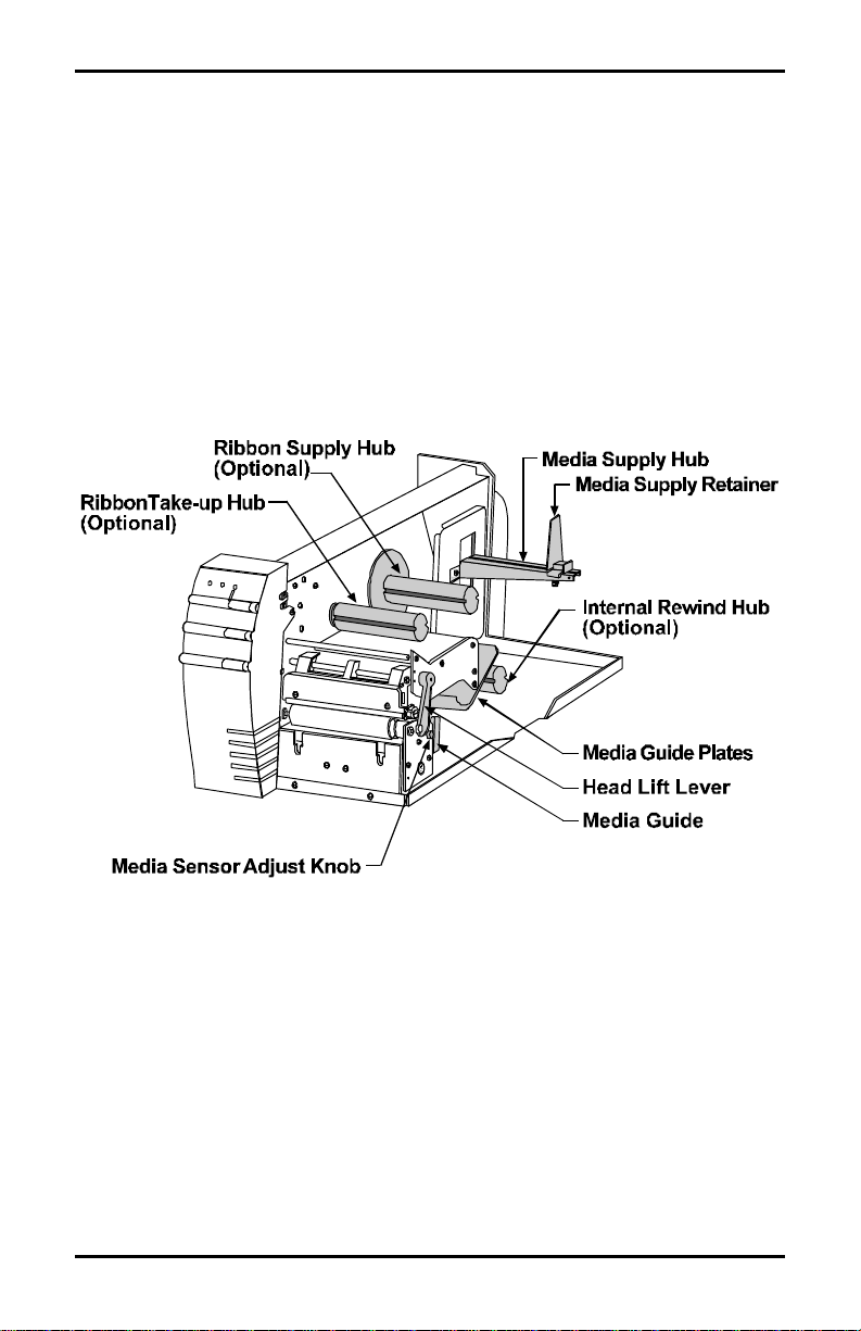
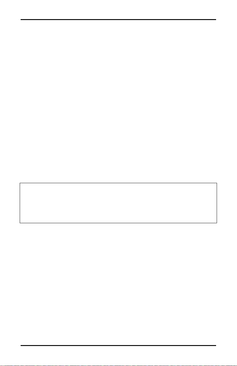
Location of Parts on Your Printer
The following illustrations show the major components of your
Printer. Figure 1-2 is a detailed view of the print mechanism from
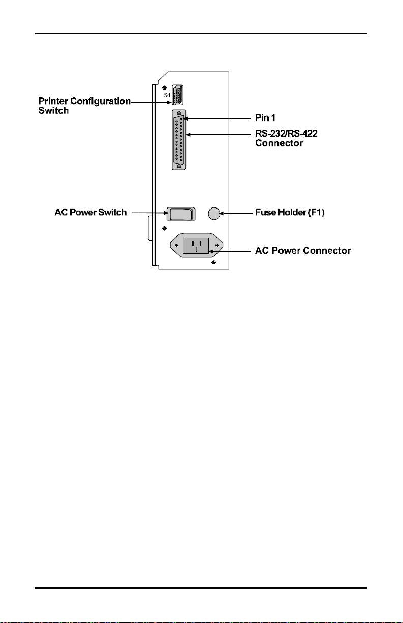
the side. Figure 1-3 is a back view of the Printer. Figure 1-5 is a
view of Printer’s switches and indicators.
In this manual we will refer to the components and connectors
depicted in these illustrations. If you are not installing the optional
Cutter or Front Rewind, then you should proceed to install the Front
Tear Bar Assembly at this time (see Figure 1.4).
Figure 1-2 Mechanism Detail
2 Allegro2
Page 11
Getting Started
Figure 1-3 Rear View
Allegro2 3
Page 12
Getting Started
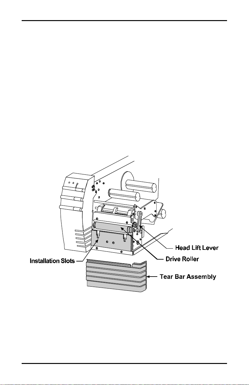
1.2 Tear- off Assembly Installation
To install the Tear-off Assembly complete the following steps:
1. Open the Printer's Side Cover.
2. Disengage the Printhead by rotating the Head-Lift Lever
counterclockwise to the ‘up’ position.
3. Fit the Tear Bar Assembly to the slots below the drive roller
and push it down until it snaps into place.
4. Engage the Printhead by rotating the Head-Lift Lever
clockwise to the ‘down’ position.
Figure 1-4 Tear Bar Assembly Installation
4 Allegro2
Page 13
Getting Started
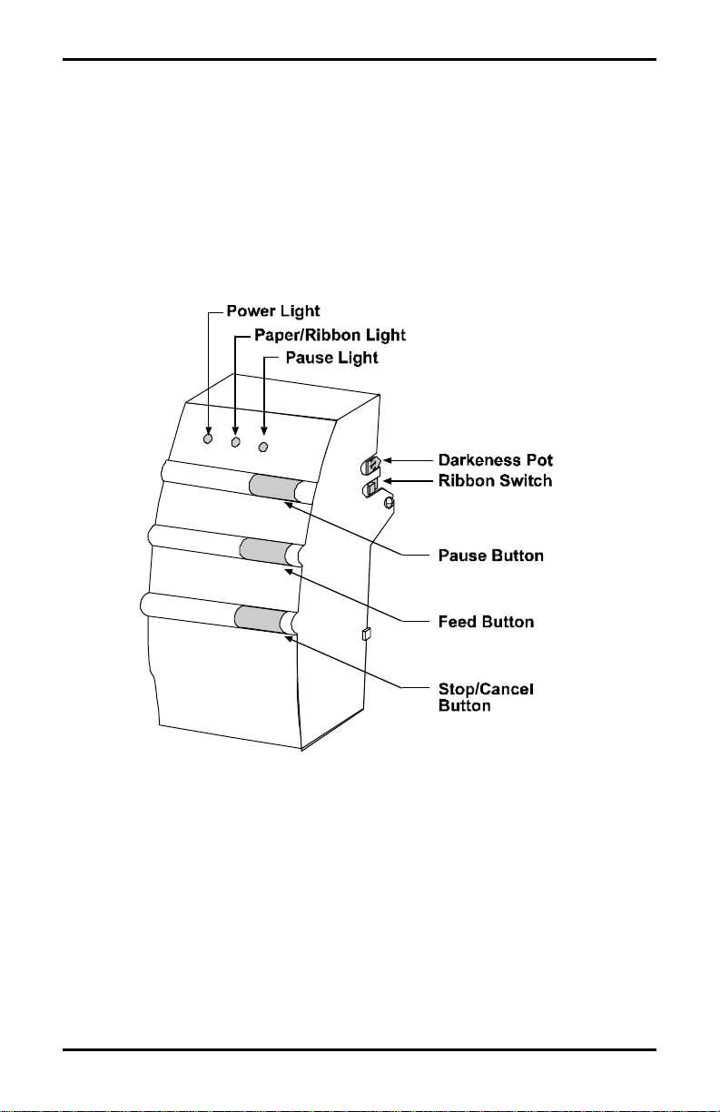
1.3 Using the Printer Control Panel
The Printer has three operator-accessible buttons, three indicators
lights (LEDs), one switch and one POT, (see Figure 1-5). A brief
description of the buttons, lights, switch and POT are listed in this
section.
Figure 1-5 Buttons, Lights and Switches
Power Light: The power light is turned on after the power switch
on the rear of the Printer is turned on.
Allegro2 5
Page 14

Getting Started
Pause Button: This button allows the operator to stop printing a
run of labels and then restart the job by pressing
the button again. Activation of the button will:
• Stop the print mechanism when the label
printing is complete.
• Turn on the pause light.
• Stop the label counter, but maintain the
count balance.
• Hold all data in memory.
Pressing the button a second time will:
• Restart the Printer.
• Print the balance of labels on the counter
unless interrupted.
• Turn ‘off’ the pause light.
Pause Light: The pause light will turn on if any of the
following occurs:
• The pause button is pressed.
• A print job is canceled with the stop/cancel
button.
• A fault occurs with the cutter or rewind
option.
Stop/Cancel Button:This button allows the operator to stop and cancel
a run of labels in the process of being printed and
continue on to the next run in the Printer’s buffer.
Feed Button: Pressing this button causes the paper to
automatically advance to the first print position of
the next label. On a new size label, 0 - 2 labels
may feed before registration occurs.
6 Allegro2
Page 15
Getting Started
Paper/Ribbon This light is activated when:
Light: • No label and/or ribbon is detected.
• The Internal Rewinder (if installed) is not
rotating, (i.e., maximum rewind capacity has
been reached).
Ribbon For direct-thermal printing, (no ribbon), slide the
Switch: switch to the ‘off’ position. For thermal-transfer
printing, (ribbon installed), slide the switch to the
‘on’ position.
Darkness POT: This POT is used to fine adjust the print darkness
due to variations in different media’s and
printheads.
Note: Do not use this control for adjusting individual label printing
jobs, rather, use the software control with the ALT-P Print
Parameters Screen in the Internal Batch Mode (see Section 4),
or the proper command in RS-232 mode to vary darkness of
printing on a per-label-format basis.
Allegro2 7
Page 16
Getting Started
1.4 Media Installation
Installation
The Printer is designed for easy label stock and ribbon installation.
A diagram located under the cover of the Printer shows the feed
path for print media. Simply lift the cover of the Printer from the
right-hand side to locate the installation instructions.
Figure 1-6 Label Loading Diagram
Labels
The Printer uses labels up to 4.65" (118mm) wide. The maximum
diameter of a roll of labels used in the Printer is 8" (203mm). If a
label is narrower than 3.5" (89mm) then the Printhead must be
adjusted off the roller. Please refer to Section 4.2.2, “Adjusting
Printhead Pressure and Support,” for more information.
8 Allegro2
Page 17

Getting Started
1.4.1 Label Loading Instructions
To load labels complete the following steps:
1. Disengage the Printhead by rotating the Head-Lift Lever
counterclockwise to the ‘up’ position.
2. Slide the Media Guide to the outer edge of the guide and
rotate it to the ‘down’ position.
3. Slide the Retainer to the outer edge of the Supply
Mount.
4. Place the label roll on the Supply Mount and slide the
Retainer firmly against it.
5. Insert the label stock as shown in Figure 1-6.
6. Route the Media Guide ‘up’ and slide it to the edge of
the Media.
7. Engage the Printhead by rotating the Head-Lift Lever
clockwise to the ‘down’ position.
If the Media is not sensing, try adjusting the sensor position by
turning the adjustment knob for the movable sensor. The gauge
behind and below the Printhead can be viewed for making this
adjustment. If the label’s edge is not detected within 12" (305mm) of
feeding, the Printer will stop and the ‘Paper Out’ Indicator will
remain illuminated. In this case, check the threading of the Media
around the bottom of the upper and lower Media Guides.
If the paper feeds forward only about 2.5" (64mm) each time you
press the Feed Button, and does not seem to be stopping on a label
edge, the Ribbon on/off Switch, (shown in Figure 1-5) was
probably turned on without Thermal-Transfer Ribbon being
installed. Slide this switch toward the front of the Printer for DirectThermal Printing.
Allegro2 9
Page 18
Getting Started
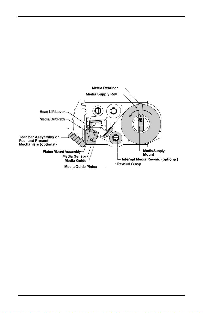
1.4.2 Ribbon Loading Instructions
Load ribbon as shown below in Figure 1-7. The ribbon can be
wound directly on to the hub and held with a clasp, or a used ribbon
core can be placed on the hub. To load the ribbon complete the
following steps:
1. Disengage the Printhead by rotating the Head-Lift Lever
counterclockwise to the ‘up’ position.
2. Slide the Ribbon on to the Ribbon Supply Hub. Route
the ribbon, (see Figure 1-7), and attach the ribbon to the
Ribbon Take-up Hub.
3. Engage the Printhead by rotating the Head-Lift Lever
clockwise to the ‘down’ position.
Figure 1-7 Ribbon Loading
10 Allegro2
Page 19
Getting Started
1.5 Using the Printer Options
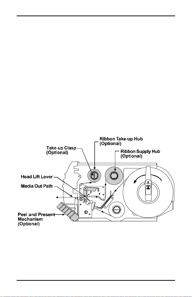
1.5.1 Available Modules
The Printer uses memory modules to expand its built-in capabilities,
primarily for the use of storing graphic images and bitmaps of
smooth fonts, and for storing label formats that can be recalled by
host computers. The Label Printer has one module slot located on
the left side for use with Memory Module Cartridges.
To install a Memory Module:
Figure 1-8 Inserting a Memory Module
Allegro2 11
Page 20

Getting Started
1.6.2 Options
Font ROM Modules
Font ROM Modules contain additional fonts that extend the
capabilities of the Internal Fonts. Each Font ROM Module comes
with documentation detailing the type and sizes available on the
module and the font number of each size used in label formatting.
Font ROM Modules are programmed at the factory and cannot be
modified later for any other purpose.
256K and 512K RAM Modules
RAM Modules are the most flexible module option for the Printer.
They provide temporary storage of data used in label-format
printing. Each module contains 256K of data storage for fonts,
graphic images or label formats.
An additional feature of the 512K RAM Module is that the Printer
will use a part of its memory to extend the Printer’s bit-mapped
label length from 8.25" (210mm) to 20.25" (514mm).
256K Flash EEPROM Module
Flash EEPROM Modules provide the same features of RAM
Modules with the added benefit of virtually permanent storage. A
Write Protect Switch on the Flash EEPROM Module can protect data
stored on the cartridge from being overwritten or erased.
Cutter
The Printer can be ordered with an Optional Cutter and tray for
cutting tags and labels, or the option can be installed at a later date.
This option can be easily attached to the Printer and once installed
can be enabled by turning ‘on’ switch 8 located on the back of your
Printer.
12 Allegro2
Page 21

Getting Started
Peel and Present
The Printer can be ordered with an optional Peel and Present
Mechanism Kit, or the option can be purchased and installed at a
later date. The Peel and Present Option automatically separates the
label from the backing, the label then sets on the Printer until it is
removed while the backing material is sent to the Internal Rewind.
This mechanism can be used with or without the Present Sensor, but
must be used in conjunction with the Internal Rewind.
Present Sensor
The Printer can be ordered with the optional Present Sensor Kit or
the option can be purchased and installed at a later date. The Present
Sensor allows the Printer to be configured for “one up” printing.
With the sensor installed and enabled, the Printer will not print the
next label in its internal buffer until the last label printed has been
removed from the Printer.
Media Rewinder
The Media Rewinder is a factory-installed option that has a couple
of functions: it rewinds the backing from labels that have been
printed in conjunction with the Peel and Present Option; in addition,
it will rewind batches of labels that have been printed for use at a
later time.
Note: The Present Sensor and Cutter can not be installed and available
at the same time.
Batch Rewind Mode is not recommended for labels less than 2".
Allegro2 13
Page 22

Getting Started
14 Allegro2
Page 23

♦ Setting Up Your Printer
2.0 Checking Voltage Selection
The standard Printer is configured for 115 VAC ±10% single-phase
50/60 Hz with a properly-grounded outlet. A small sticker next to
the power cord connection indicates the power requirements.
For international markets, there is a 230 VAC version available. If
you are uncertain about the configuration of your Printer, or the
outlet you are connecting to, check with a qualified service
technician to verify the installation before connecting power.
2.1 Power Up Self-Test
Once labels are installed in the Printer as described in Section 1.4, a
Self-Test should be performed. The Printer will power up in the
Self-Test Mode when the Feed Button is pressed as the Printer is
being turned on. Initial power up will take approximately 7
seconds. The Printer should be loaded with 4.25" (108mm) wide
stock whenever this test is conducted. The Self-Test prints across
the entire width of the Printhead. Expect a brief hesitation of up to
15 seconds before the Self-Test begins to print.
Allegro2 15
Page 24
Setting Up Your Printer
If a label edge is not detected within 12" (305mm) of stock, the
Printer will stop feeding labels. If this occurs, refer to Section 1.4
and reload the Media, see Figure 1-6 to find the location of the
Media Sensor. If a label edge is detected, the Printer will begin to
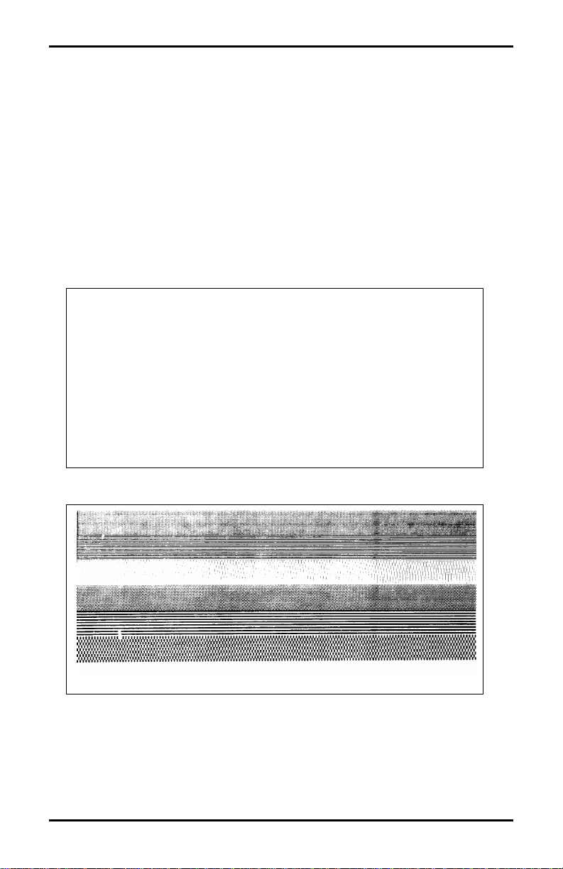
print the Self-Test pattern. An example of a test pattern is shown in
Figure 2-1. After the test pattern has printed successfully, the
Printer’s power switch must be turned ‘off’ and then turned ‘on’
again to reset the Printer.
THR JANUARY 30 , 1997 15:17 030
VER : CA02-01 0111 01/16/97
SYSTEM ROM CHECKSUM : B763 IS GOOD
SYSTEM ROM CHECKS GOOD
SERIAL PORT BAUD RATE IS 96ØØ
TRANSFER SWITCH I S ON
SETUP SWITCH 1 2 3 4 5 6 7 8
ANALOG INPUT VALUES:
PAPER: 227 EDGE: 152 VOLT: 121
TEMP; 069 POT: 169
ON ON ON OFF OFF OFF OFF OFF
Figure 2-1 Test Label
16 Allegro2
Page 25
Setting Up Your Printer
2.2 Interfacing to the Printer
Depending on your application, the Printer can be set up in different
ways. Table 2-1 lists the interface cables that should be used for
each situation. If your application is not listed below, refer to
Appendix B which contains the communications information
necessary to connect the Printer to virtually any ASCII device.
Part Number Description
556000 Printer to CRT Terminal (DB25P) RS-232
556001 Printer to PC 9 Pin (DB9S) RS-232
556002 Printer to PC 25 Pin (DB25S) RS-232
899516 Printer to PC Parallel Port (DB25P)
Table 2-1 Interface Cables
For most applications, the interface between the Printer and host
device will be RS-232C. The cable necessary to connect the Printer
to the host will be either a straight cable or a null-modem cable. This
cable connects the DB-25 connector labeled ‘Serial Port’ on the back
of the Printer to the serial data connector on the host device.
The pin configuration of the Printer for most descriptions of the RS232 interface on a DB-25 connector is Data Terminal Equipment,
(DTE). Pin 2 is transmit, pin 3 is receive and pin 7 is ground.
The Printer supports both Xon/Xoff and CTS/DTR handshaking.
Whenever the Printer is interfaced in a mode that does not use the
CTS/DTR pins, a jumper should be placed on the PC side of the
cable between pins 4 and 5 (CTS/RTS) to bypass the operation of
those control lines. A custom cable must be obtained for this
purpose.
For connection to most host systems, Xon/Xoff handshaking
reduces the number of wires necessary in the interface cable. For
interfacing RS-422 devices, the Xon/Xoff handshake is the only
appropriate method.
Allegro2 17
Page 26

Setting Up Your Printer
2.3 Sample Installations
In this section, four typical installations are reviewed, CRT terminal,
PC, minicomputer, and mainframe computer. Cable connections for
similar installations are listed in Appendix D. This section outlines
the procedures that will enable you to set up the Printer for various
installations.
Connecting to a CRT
A typical application for a CRT-based system is generating and
printing labels that are stored on an optional Flash Module. First,
connect the Printer to the CRT with the cable number 556000 and
turn on switch 7 at the rear of the Printer. Next, plug the module
into the slot on the side of the Printer to store label formats on the
module. For a detailed explanation of the operation of this
configuration, refer to Section 3, “Creating Labels Using Internal
Batch Software.”
Connecting to a PC
A cable should be selected (refer to Table 2-1), and connected to a
PC via a RS-232 port. It is recommended that you use a RS-232 port
to allow for two-way communication with the Printer. The RS-232
communications port can be connected with one of two possible
configurations: a 9 pin cable (part number 556001) or a 25 pin cable
(part number 556002).
Note: DB25S (socket/female) connectors on most PCs are
normally parallel ports; DB25P and DB9P (pin/male)
are normally serial ports.
18 Allegro2
Page 27

Setting Up Your Printer
If your Printer is controlled by a third-party software package,
please refer to the operator’s manual supplied with the software
package for operating instructions. For detailed explanations of the
Printer’s commands and label format structure, refer to the
Programmer's Manual.
A typical application for a PC-based system is printing labels for
manufacturing production in a Batch Mode. In these applications, a
data-base of part numbers, descriptions, warehouse locations, and
shipping weight information may be obtained through the PC.
Through an entry screen, the operator selects the type and quantity
of labels to be printed. The PC sends the data serially to the Printer
and the operator receives the labels requested.
Connecting to Your Minicomputer
Connecting the Printer to most minicomputers is similar to
connecting to a PC. Most minicomputers made by Digital
Equipment, Hewlett Packard, Unisys, etc., have ASCII RS-232C
serial ports similar to PCs. Interfacing to IBM systems sometimes
requires a protocol converter. The cable you select for connecting
the Printer to a minicomputer will vary depending on the type of
computer system you have. Diagrams in Appendix D describe a
straight serial cable and a null modem cable, one of these two cables
should work on your system.
Connecting to Your Non-ASCII Device
The Printer uses the standard ASCII for conversion of byte patterns
to characters. The standard port for receiving data expects
asynchronous ASCII serial data. If your host system uses an
interface other than ASCII character-based RS-232C, you will need
an interface converter.
Some hosts, such as IBM mainframe equipment, do not use the
ASCII standard for data encoding, rather many IBM machines use
EBCDIC.
Allegro2 19
Page 28
Setting Up Your Printer
To connect the Printer to EBCDIC devices, or devices with any
other data encoding standard, a protocol converter must be used. A
protocol converter translates the bit patterns of one standard to the
bit patterns of another standard. Some protocol converters are also
interface converters, combining two functions into one box. Many
of these products are available from the manufacturer of your
computer equipment or your local reseller. Please note that
additional commands may be necessary to control the protocol
converter you select for your data interface.
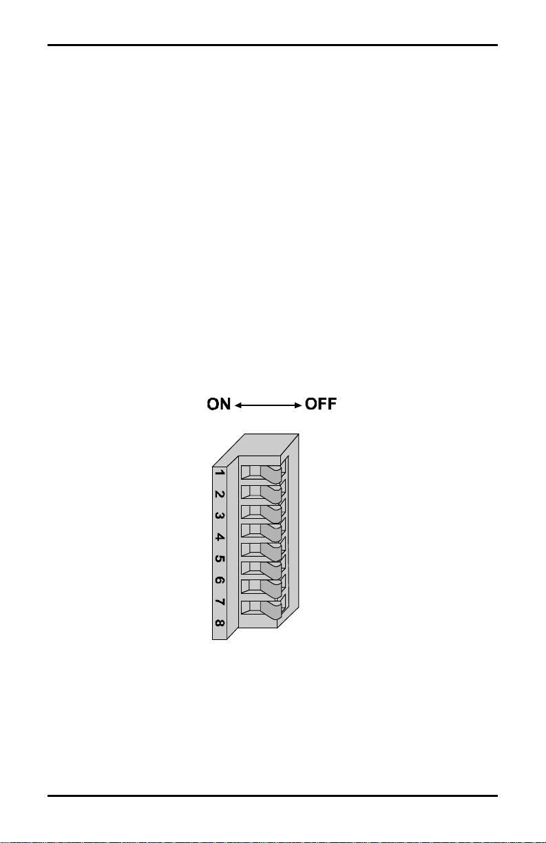
2.4 Switch Settings
There are eight switches located on the back of the Printer as shown
in Figure 2-2. The function of the switches are to control
communications and are explained on the following pages.
Figure 2-2 Switch Settings
20 Allegro2
Page 29
Setting Up Your Printer
Setting the Baud Rate
For all modes of operation, you must set the baud rate of the
interface. On the back of the Printer, you will find a single eightposition Dip Switch, positions 1, 2, and 3 control the setting of the
baud rate.
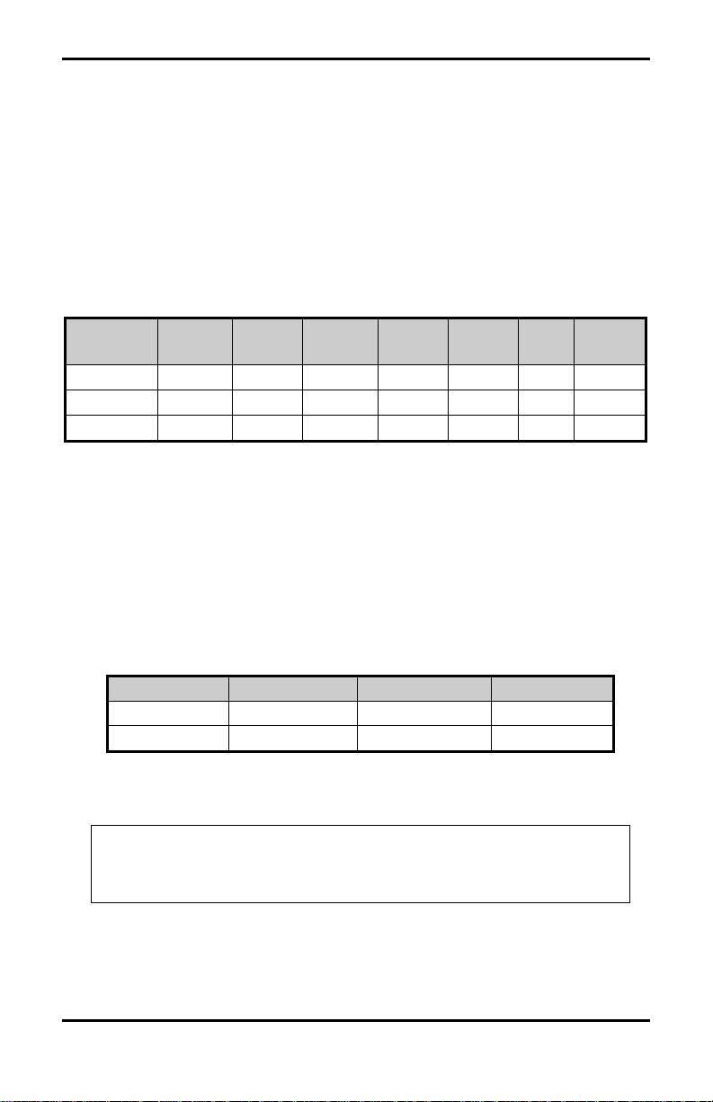
The following table provides the position of the three switches and
the corresponding baud rate that can be obtained by each setting:
Baud 9600 4800 2400 1200 600 300 9600
Test
SW-1 off off off off on on on
SW-2 off off on on off off on
SW-3 off on off on off on on
Table 2-2 Baud Rate
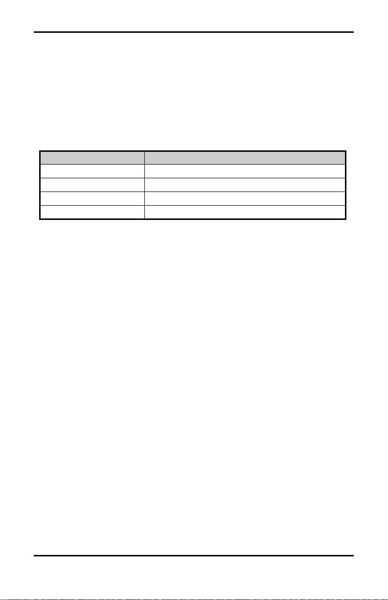
The Printer can accept 7- or 8-bit data, while ignoring parity. It also
requires at least one stop bit. This configuration assures the highest
degree of compatibility with most serial devices, even if the data
format arrangement of the host cannot be modified. Switch SW-4,
located on the back of the Printer, selects the word length.
SW-4 Data Bits Parity Stop Bits
on 7 none 2
off 8 none 1
Table 2-3 Word Length
Note: It will be necessary to select the 8-bit mode if you want
to access the foreign language characters. These
characters are available in fonts 1 through 6 and 9.
Allegro2 21
Page 30

Setting Up Your Printer
Other Switches
Switch SW-5: Controls the label edge offset, when the switch is on,
the label edge offset will default to 0250. When the
switch is off, the label edge offset will default to 0220.
Switch SW-6: Present Sensor Option
Switch SW-7: Enables the Internal Batch Software Program. This
program is explained in Chapter 3. There is a software
command that will perform the same option as this
switch; it is the STX g Command.
Switch SW-8: Controls the optional Cutter.
SW-5 Prodigy Compatibility
On Prodigy
Off Allegro
SW-6 Present Sensor Option
On Present Sensor Enabled
Off Present Sensor Disabled
SW-7 Internal Batch Software
On Internal Batch Enabled
Off Internal Batch Disabled
SW-8 Cutter
On Cutter Enabled
Off Cutter Disabled
Table 2-4 Switch Settings and Functions
22 Allegro2
Page 31

Setting Up Your Printer
2.5 Programming Commands
In order to be ready for a command sequence, the Printer must first
receive a special character called an “attention getter” that informs
the Printer that it is about to receive a command and the type of
command it will be. Immediate Commands, System-Level
Commands, and Font-Loading Commands each have their own
attention getter. The attention getter character is followed by a
command character that tells the Printer what action to take.
ASCII Char. Decimal
Value
SOH 1 01 Ctrl A Immediate Commands
STX 2 02 Ctrl B System-Level Commands
ESC 27 1B Ctrl [ Font-Loading Commands
HEX
Value
DOS
Prompt
Attention Getter For
Table 2-5 Attention Getters
When the Printer receives an Immediate Command it will cease
whatever it is doing and perform that command. Commands of all
types must be in this sequence:
1. Attention Getter
2. Command Character
3. Parameters that must be entered by the user (if any).
Command
Character
# N Y Reset
A N Y Send ASCII status string
B N N Toggle pause
C N N Cancel
D N N SOH shutdown
E N Y Send batch quantity
F N Y Send status byte
Must Enter
Parameters
Printer
Responds
Command
Table 2-6 Immediate Commands
Allegro2 23
Page 32

Setting Up Your Printer
The System-Level Commands are used to create formats, load and
store graphic information, and control the Printer. Table 2-7
provides a brief description and format of each System-Level
Command Character.
Char Description Format
A Set time and date Format: AwmmddyyyyhhMMjjj
16 digits total.
w
mm
dd
yyyy
hh
MM
jjj
a Enable feedback characters Returns 30 after each label and 31 after each
batch of labels
B Get Printer time and date
information
c Set continuous paper length cnnnn = length of paper to feed per label
d Set Printer to double buffer
mode
E Set quantity for stored label Ennnn = Set Quantity for stored label
e Select edge sensor Used for "see through" media sensing
F Form feed Feeds one label at a time
f Set form stop position
(Backfeed)
G Print last label format
I Input graphics data block
"See Programmer's Manual for
format"
i Download scalable font
J Set pause for each label
K Extended System Commands Kn n =
k Test RS-232 Port Y=ok Sends character "Y" to RS-232 port
L Enter Label Formatting Mode
M Set maximum label length Mnnnn = 4 digits (default) Maximum 12 inches
Print time and date to port
Used to print a label while a second is formatting
in memory
Set distance to peel (tear off) position fnnn =
3 digits from sensor
A bank designation, an optional word length
modifier, a format designation, and up to a 16character string to identify the stored image data
Q - For query
D - Database Configuration
S, W, or M - Set configuration
R - Reset
fxxxx- 4 digit number, Distance between TOF
sensor and stop position
r - Resettable counters reset
= 1 digit week, 1 is Monday
= 2 digits for month
= 2 digits for day
= 4 digits for year
= 2 digits for hour (24 hr ft)
= 2 digits for minutes
= 3 digits for Julian I.D. value
Table 2-7 System-Level Commands
24 Allegro2
Page 33

Setting Up Your Printer
Char Description Format
m Set metric flag, enter metric mode All references set to metric until reset
n Clear metric flag, return to inch mode All references set to inch mode
O Form edge offset (start of print
position)
o Cycle cutter
P Enter character dump mode
p Controlled pause
Q Clear all memory modules
q Clear module qx = Module I.D. (Uppercase)
r Select reflective sensor Used for "black-strip" media sensing,
S Slew (feed) speed Sx x = A -C (1.0 to 2.0 ips)
s Set up for one print buffer Set for 1 dot buffer processing. Use for
T Printhead dot pattern test label
t Test RAM memory module
(Must be in Test Mode)
U Label format field replacement
V Software switch settings Vn n = 4-Label Present, 2-Internal
v Firmware version information Sends version string to Host
W Request memory module information Wx x = F-font, G-graphic, L-label
w Test FLASH module memory Takes about 90 seconds
x Delete module file xMF name M=Module I.D, F=file type
X Set default module bank Xa a - A = memory module A
Y Output sensor values Dumps sensor values status to
Z Print internal information and dot
pattern
Onnnn = 4 digits, in/100 or mm/10
(e.g. continuous tags, butt-cut labels.
Stripe must be printed on back side of
media)
full length dot buffer processing.
a bbbK ‘Module Good’
bbb = 256 or 512, for size of module
Batch, 1-Cutter Enable
RS-232 port
Zx x= Module I.D
Table 2-7 System-Level Commands (Continued)
Allegro2 25
Page 34

Setting Up Your Printer
A STX L Command switches the Printer from the System Level to
the Label-Formatting Mode. All command characters after STX L
are interpreted as Label Formatting Commands until the LabelFormatting Mode is terminated with the Command Character E. All
Label -Formatting Commands are terminated with hex value 0D.
CC Description Format
Set cut by amount (4 digits)
:
The cutter function will perform a cutting
action after the number of labels specified
A Set format attribute An n=1-XOR, 2-Transparent,
C Set column offset amount Cnnnn nnnn= in/100 or mm/10
c Set cut by amount (2 digits) cnn nn = 2 cut amount
D Set height and width dot size h = Horiz. dot size; can be 1 or 2
E Terminate field generation and print label
G Place data in global register
H Enter heat setting
(The amount of heat applied per dot row,
can be used to help control print quality)
m Set metric mode The Printer must be reset in order
M Set mirror image mode
('Mirror Images' current formatted label)
P Print speed Px x = A -C (1.0 to 2.0 ips)
p Set label backup speed px x x = A -C (1.0 to 2.0 ips)
Q Enter quantity of labels to print Qnnnn nnnn = quantity
R Set row offset amount Rnnnn nnnn = in/100 or mm/10
r Recall stored label format rnn...n nn...n Label name of up
S Slew (feed) speed Sx x = A -C (1.0 to 2.0 ips)
s Store label format in module
T Set field data line terminator Tnn nn = 2 digit ASCII Hex
U Make previous field a string replace field
:nnnn
nnnn = 4 digits of labels printed
before cut. Default = 0001
3-Opaque, 5-Inverse
v = Vert. dot size; can be 1,2, or 3
(0.005" steps) Default is “D22”
Hnn nn = 2 digits. 1 - 30
10 is nominal and default
to return to standard measure
'M' must be re-sent to cancel.
* *Will not mirror polygons.
to 16 char. terminated by CR
sann...n a - destination module
A memory module A
nn...n - label name (16 char. max)
00 - FF
Table 2-8 Label-Formatting Commands
26 Allegro2
Page 35

Setting Up Your Printer
CC Description Format
X Terminate label formatting mode
y Select font symbol set (optional scalable
fonts only)
z orZZero (0) conversion to "O"
eliminates slash (/)
+ Make last field entered increment numeric +pii Make last entered field
- Make last field entered decrement numeric -pii Make last entered field
> Make last field entered increment
alphanumeric
< Make last field entered decrement
alphanumeric
^ Set count by amount ^nn Set count by amount
y S xx
y = ASCII (0x79)
S = ASCII (0x54)
xx = symbol selection
incrementing
p = Zero fill character
ii = Data added to field
decrementing
p = Zero fill character
ii = Data subtracted from field
>pii Make last entered field
incrementing 0 - Z
p = Zero fill character
ii = Data added to field
<pii Make last entered field
decrementing 0 - Z
p = Zero fill character
ii = Data subtracted from field
nn = 2 digits
Skip # of labels before updating
count fields and time fields
Table 2-8 Label-Formatting Commands (Continued)
There are two special commands used by the Printer, the STX S,
(Recall Global Data), and the STX T (print date and time)
Commands. Unlike the other Label-Formatting Commands, which
follow the STX L Command, these special commands are entered
directly into the data field.
Character Description
<STX>S Recall global data and place in field
<STX>T Print time and date
Table 2-9 Special Label-Formatting Commands
Allegro2 27
Page 36

Setting Up Your Printer
The commands used for bit-mapped font loading are usually
generated by font-creation software. However, the assigned font ID
number command must be sent to the Printer before the font file.
Font-Loading Commands are listed in Table 2-10.
CC P PR Description
*c###D N N Assign Font ID Number
### = ID Number 100 to 999
)s#W Y N Font Descriptor
*c#E N N Character Code
# = ASCII Value of Character
(s#W Y N Character Download Data
# = Bytes of Bit-mapped Data
Table 2-10 Font-Loading Commands
CC = Command Character
P = Must Supply Parameters? (Y/N)
PR = Printer Responds? (Y/N)
2.6 Programming Examples
<STX> L <CR>
H07 <CR>
D11 <CR>
19110080100002510K OHM 1/4 WATT <CR>
1a6210000000050590PCS <CR>
E
10K OHM 1/4 WATT
Figure 2-3 Sample Label
28 Allegro2
Page 37

Setting Up Your Printer
The example shown below prints out a Code 3 of 9 bar code with a
wide to narrow bar ratio of 3:1 and can be used to print any of the
bar codes shown in Appendix C by altering the example's fields.
Refer to Figures 2-4 and 2-5 for a brief explanation of the data
fields.
<STX>L<CR>
D11<CR>
1A93040001501000123456789<CR>
121100000000100Barcode A<CR>
E
<STX>L Syntax L on line 1 is used to enter the label formatting mode.
Figure 2-4 Example line 3
Figure 2-5 Example line 4
Allegro2 29
Page 38

Setting Up Your Printer
30 Allegro2
Page 39

♦ Creating Labels Using Internal Batch
Software
3.0 Introduction
The Printer can be used in any one of three different operating
modes: RS-232 to a host computer; a PC with a compatible software
package, or; LINK MC2 CRT with Internal Batch Software, a standalone label creation package developed especially for the Printer.
This section focuses on the Printer's internal labeling software
program.
The program uses two screens, one to create or modify a label and
the other to print a label. A system maintenance screen is included
for printing test labels, copying and formatting memory modules,
and performing several other functions.
Internal Batch Modules can store up to 200 label formats per Flash
Module and each can hold up to 128K of memory shared between
label formats and graphic images. You can purchase as many
Internal Batch Modules as you need for your applications.
Allegro2 31
Page 40

Creating Labels Using Internal Batch Software
3.1 The Printer Used With a LINK CRT
A number of steps are required before you can begin to format and
print labels with the Printer. These steps are explained in the
following pages.
1. Connect Cables
Verify that the LINK CRT and the Printer’s main Power
Switches are ‘off’. Connect the LINK CRT terminal to the
Printer with the supplied cable. Plug in the supplied power
cords for the Printer and the LINK CRT terminal.
Note: The Printer connects to the LINK MAIN port, not the
LINK parallel port.
2. Check LINK CRT Settings
The LINK CRT is shipped ready for use with the Printer and the
settings are pre-set and should be changed only when necessary.
If the terminal's settings have been changed since shipment from
the factory, follow the terminal's set-up procedure to reset all
default settings,(see Table 3-1). The Printer will set all remaining
parameters; however, these settings are not saved in the CRT's
RAM. To save them, follow the CRT's "save changes" routine
after normal operation is established.
32 Allegro2
Page 41

Creating Labels Using Internal Batch Software
Function Default
Function Settings
Settings
Handshake: none F1 CTRL W
Mode: FDX F2 CTRL X
Data Bits: 8 F3 CTRL Y
Stop Bits: 1 F4 CTRL Z
Parity: none F5 ALT S
Baud Rate: 9600 F6 ALT P
Keys: US F7 ALT I
Blk End: US/CR F8 ALT X
Auto NL: on F9 ALT F
CR: CR
Compatible: LINK MC 2
Table 3-1 LINK CRT Default Settings
3. Select Stand-Alone Labeling Software Mode
The Printer is shipped in the RS-232 mode for use with PCs. To
use the CRT, turn Dip Switch S1-7 to the ‘on’ position and
insert the 256K Flash Module into the Printer before turning the
power on. Plug the module into the module slot as described in
Section 1.6. Ensure that the lettering is facing toward the front
of the Printer. When the Printer is turned on it will recognize
that the module has been formatted as an Internal Batch
Software Module and will run the Internal Batch Program. If the
module has not been formatted, the following screen will
appear:
BATCH SYSTEM INITIALIZATION
INSERT Flash MEMORY MODULE AND PRESS:
I: INITIALIZE NEW MODULE.
ENTER: ENTER BATCH SYSTEM.
Esc: EXIT TO RS-232 MODE.
Allegro2 33
Page 42

Creating Labels Using Internal Batch Software
To format the module hit "I" and the following screen will appear:
MODULE MEMORY TEST AND FORMAT
WARNING !! MODULE DATA WILL BE LOST !!
PLUG IN MODULE. PRESS ENTER (Esc TO CANCEL)
Hit "Enter" to begin formatting the module, the following screen
will appear:
MODULE MEMORY TEST AND FORMAT
WARNING !! MODULE DATA WILL BE LOST !!
MODULE UNDER TEST PLEASE WAIT !!
pppppppppvvvvvvvv
MODULE MEMORY IS GOOD
PRESS ENTER TO TEST ANOTHER "Esc TO EXIT"
once the module has been formatted, hit "Esc" to enter the Internal
Batch Mode.
Note: Use a small screwdriver, turn the module's Write Protect
Switch to the ‘off’ position. Label formats cannot be sent
to the module if the switch is in the ‘on’ position. To
prevent accidental changes or modifications to formats,
turn the Write Protect Switch back to the ‘on’ position.
4. Verify Setup, Power Up, and Load Media
Check that all connections are made and that Dip Switch S1 is
correctly configured. Turn on the CRT and Printer Power
Switches. Press the F1 key on the CRT several times. The
Create/Modify Label and Print Label Screens should toggle back
and forth. If this does not happen, re-check the CRT settings,
check the interface cable. If the screens still do not appear,
contact your local representative. If the module has not been
formatted for Internal Batch, the set up screen will appear until
you hit the I option. If steps 1-4 have been successfully
completed, load the Printer with media.
34 Allegro2
Page 43

Creating Labels Using Internal Batch Software
3.2 Formatting and Printing Labels
Formatting labels is designed to be a three step procedure:
1. Selecting an operating screen.
2. Specifying where on the label to place text and/or barcodes.
3. Printing the actual labels.
Available Fonts and Barcodes
All available character font sizes, barcodes, multiplication
parameters, and resulting character sizes are illustrated and
explained in Appendix C. Each font and barcode has a name
associated with it for use in the Create/Modify Label Screen.
Alphanumeric fonts are 0 through 9, barcodes with human-readable
interpretation lines are uppercase A through R, except P (Postnet).
Barcodes without human-readable interpretation lines are lowercase
a through r, all fonts and barcodes can be magnified in height and
width.
Menu Screens
The following three menu screens are available in the Printer's
internal labeling software program:
1. Create/Modify Label
2. Print Label
3. System Maintenance
Function Keys
Nine function keys labeled F1 to F9 are used extensively in the
label-formatting process. Some functions can also be controlled by
the ALT keys. To use the ALT functions, press and hold the ALT
key at the same time as you press another key. The ALT functions
and the function keys include the following functions:
F1 or Esc (SWITCH): Toggles between the Print and Create/Modify
Label Screens. F1 can be used only in the
Label Name position of the Create/Modify or
Print screens.
Allegro2 35
Page 44

Creating Labels Using Internal Batch Software
F2 (LIST): Displays a library listing of every label format and/or
graphic image loaded in the current memory module. F2
can be used only when the prompt is in the Label Name
position of the Create/Modify or Print Screens.
F3 (COPY): Used in the Create/Modify Label Screen only. Enter a
new Label Name, then press the F3 key. The message
below will appear.
LABEL NAME:________________
NEW LABEL NAME:__________________
Enter the name of an existing label already in memory and press the
‘enter’ key. A new label is then created with the same data as the
source label, which allows immediate editing of the new label
format. The F3 copy feature will also copy the current field to the
next field when the cursor is at the farthest left position of the
Create/Modify Label Screen.
F4 (KILL): Used in the Create/Modify Label Screen only. Enter an
existing label name, followed by the F4 key. The
message "Remove Label? (Y/N)" will appear. Answer
yes or no with the Y or N key. If Y, the label is
permanently removed from the memory module , if the
Write Protect Switch is ‘off’. When creating or
modifying a label format, the F4 Kill Feature also
deletes a single format line one at a time. Move the
cursor to the farthest left position of the screen, then
press F4. The current line will be deleted.
F5 and ALT-S: Calls up the System Maintenance Screen. All system
maintenance functions are described in Section 3.5.
36 Allegro2
Page 45

Creating Labels Using Internal Batch Software
F6 and ALT-P: While in the far left position of the Create/Modify
Label Screen or the Sample: position of the Print Label
Screen, press ALT-P to bring up the Print Parameters
Windows. It will look like this:
PRINT ADJUSTMENTS
HEAT FACTOR: 10
PRINT SPEED: C
SLEW SPEED: C
DOT PATTERN (5 mil): 1 X 1
LABEL ADVANCE: 02.20
FORM EDGE OFFSET: 02.20
ROW OFFSET: 00.00
COLUMN OFFSET: 00.00
COUNT BY: 01
MAX. LABEL WIDTH: 04.10
MAX. LABEL LENGTH: 12.00
CONTINUOUS FORMS: NO
ACTIVE BUFFERS (1/2) 01
CUT BY (# PER CUT): 0001
SENSOR TYPE: EDGE
EDGE?REFLECTIVE E
Figure 3-1 ALT-P Screen
Print parameters include row and column offsets, form edge offset,
label advance, dot size, heat setting, etc. Use the arrow keys to move
from one position to the next. Key in any values that need to be
changed. Press the Esc key to exit the window. A description of
each print parameter along with default values and valid settings are
listed in Table 3-2.
Allegro2 37
Page 46

Creating Labels Using Internal Batch Software
Description Default Range
Heat Factor 10 0 to 20
Print Speed C C-E
Slew Speed C C-E
Dot Pattern Wide 1 1 or 2
Dot Pattern High 1 1 to 3
Label Advance
(Back Feed)
220 Form Edge Offset to
Form Edge Offset + 200
Form Edge Offset 220 050 to 999
Row Offset 000 000 to 999
Column Offset 000 000 to 410
Update Count on 01 01 to 99
Max. Label Width 410 050 to 410
Max. Label Length 1200 0500 to 9999
Active Buffers 1 1 or 2
Cut By Amount 0001 0001 to 9999
Edge/Reflective E E or R
Table 3-2 Print Parameters
If ALT-P parameters are changed while in the Create/Modify Label
Screen, the changes are saved with the label format. If they are
changed in the Print Label Screen, they are not saved and will affect
only the current print job. Changing parameters in the Print Label
Screen is useful when testing a new label to determine optimum
print parameter settings for that particular format.
F7 and ALT-I: This function is used in the Create/Modify Label
Screen to insert a new field description line between
existing field description lines on the screen. It is
especially useful when the Repeat Function is used and
other lines on the screen are already below the field to
be repeated.
F8 and ALT-X: May be pressed while the cursor is located at the ROT
field of the Create/Modify Label Screen. It will cause
the Print Screen to show a pre-set quantity of 1 for the
purposes of printing a test label.
38 Allegro2
Page 47

Creating Labels Using Internal Batch Software
F9 and ALT-F: Feeds one label at a time from the Print Label Screen.
It operates the same way as the front panel Feed
Switch. This function is useful when loading new
media to register the photoelectric sensor.
Other Important Keys
Several other keys are used in the editing and printing steps and are
described below.
Return: Enters an answer for the prompt and moves the
cursor to the next position if the answer is
acceptable.
arrow keys: Used to move the cursor left and right and up and
down in the Create/Modify and Print Screens. Up
and down arrows in the Create/Modify Screen are
restricted to the ROT position.
ESC: Ends the formatting for a particular label and
returns the cursor to the top of the screen. The Esc
key allows the F1 key to be used to switch screens.
It is also used to exit ALT-S and ALT-P screens.
Backspace: Erases one character.
Home: Deletes the current field and moves the cursor to the
beginning of that field.
Allegro2 39
Page 48

Creating Labels Using Internal Batch Software
3.3 Create/Modify Label Screen
This section describes how to create a new label. Before beginning,
a good tool to have on hand is a ruler marked in tenths of an inch
because all the label format print positions are specified in tenths
and hundredths of an inch. The procedure for creating a new label
is as follows:
1. Power up the CRT terminal with the switch on the front of
the unit. Turn the Printer on with the Power Switch located
in the back of the Printer. The CRT screen will look like
this:
PRINT LABEL
MODULE NAME: ________________
LABEL NAME: ________________
QUANTITY: ________________
Figure 3-2 Print Label Screen Header
Press the F1 key, and the screen will look like this:
CREATE/MODIFY LABEL
MODULE NAME: ________________
LABEL NAME: ________________
ROT FNT XW XH BH ROW COL TYPE DATA/PROMPT
--- --- -- -- --- ---- ----- ----- ------------------------
Figure 3-3 Create/Modify Label Screen Header
40 Allegro2
Page 49

Creating Labels Using Internal Batch Software
2. The software’s two operating screens are Create/Modify
Label and Print Label.
All data is entered into fields. A field is a set of information
such as a product name, address, barcode, number, etc., that
is specified on individual lines on the CRT screen. Because
fields are independent of each other, it is possible and
sometimes desirable, to place two or more fields on the
same horizontal or vertical measurement. Be careful not to
print one field over another.
Allegro2 41
Page 50

Creating Labels Using Internal Batch Software
Notice in the upper left-hand corner of the screen that the current
Field Number is displayed. This program can accommodate up to
200 fields per format. Use the return key or the arrow keys to move
the cursor around within the 200 fields, one field at a time. A sample
label format is illustrated in Figure 3-4. To create a label, press the
F1 key to return to the Create/Modify Label Screen. The cursor will
be in the Label Name Position.
CREATE/MODIFY LABEL
MODULE NAME: ________________
LABEL NAME: ________________
ROT FNT XW XH BH ROW COL TYPE DATA/PROMPT
--- --- -- -- ---- ---- ---- ----- -------------------------1 2 2 2 0.00 03.70 00.20 D NYLON INSULATED TOGGLE SWITCH
1 X 1 1 0.00 03.60 00.10 D B370040003003
1 6 2 2 0.00 00.30 00.20 D DA100-PB-B
1 X 1 1 0.00 00.20 00.15 D L400080
1 Y 1 1 0.00 01.50 02.85 D SW5
1 a 6 2 0.40 01.35 00.15 D DA100 PB B
1 1 2 2 0.00 01.20 00.65 D DA100 PB B
1 3 1 1 0.00 03.20 00.20 D SWITCH ACTION
1 1 2 2 0.00 03.00 00.20 D SPST on-None-OFF
1 3 1 1 0.00 02.70 00.20 D TERMINALS
1 1 2 2 0.00 02.50 00.20 D SOLDER/SPADE
1 3 1 1 0.00 02.20 00.20 D RATING
1 1 2 2 0.00 02.00 00.20 D @ 10 AMPS, 125VAC
1 X 1 1 0.00 01.90 00.10 D B200160003003
1 X 1 1 0.00 02.40 00.13 D L194003
1 X 1 1 0.00 02.90 00.13 D L194003
1 0 1 1 0.00 00.00 00.15 D ALLEGRO2 LABEL PRINTER
Figure 3-4 Sample Label Format
3. Enter an alphanumeric name of up to 16 characters for this
label, followed by the return key. The message "New Label
Format?" appears. Answer Y or N. If yes, the cursor moves
to the ROT position. If the cursor does not move past the
New Label Format position, the memory module 's Write
Protect Switch is ‘on’; turn it ‘off’ to continue.
42 Allegro2
Page 51

Creating Labels Using Internal Batch Software
4. The Printer can print fonts, barcodes, and graphics at 0, 90,
180, or 270 degree rotations. Valid responses to the ROT
prompt include:
1 = 0 degrees
2 = 90 degrees
3 = 180 degrees
4 = 270 degrees
5. In the FNT position, enter the type of font you want to
print. This can be an alphanumeric font or a barcode. Enter
one of the following:
• An alphanumeric font type, followed by the return key.
Choices are 0 through 8. See Appendix C for examples
of each available font type and for the actual printed size
of the various fonts using different multiplication
factors.
• An alphanumeric CG Triumvirate font type, followed
by the return key; the only choice is 9. See Appendix C
for examples of each available font type and for the
actual printed size of the font using different
multiplication factors. The point size is selected in the
barcode height field. Values are 001 through 010.
• A barcode, followed by the return key. Choices are
uppercase A through R, except for P (Postnet). For
barcodes that include the human-readable interpretation
line, or lowercase a through r for barcodes without
human-readable lines, see Appendix C for examples of
each available barcode.
• X is a special font choice that is not actually a font. The
X font selects box and line drawing. Later, in the
Data/Prompt Position, the format for lines or boxes
must be entered .
Allegro2 43
Page 52

Creating Labels Using Internal Batch Software
• Y is another special font choice that is not actually a
font. The Y font selects a graphic image that has already
been loaded into the memory module. If this font is
selected, enter the name of the graphic image in the
Data/Prompt position. This name must be uppercase
characters when printing an image.
If any letter or number is entered in the FNT Position
other than those specified above, the following error
message will appear:
INVALID FONT TYPE
You will need to re-enter the data. After entering the
desired font and pressing the return key, the cursor will
move to the XW position.
6. The XW and XH positions are used to magnify widths and
heights of fonts, and to change the wide/narrow ratio of
barcodes.
• If you wish to magnify the width of a font, valid
responses are 1 through 9 and A through O. The default
value is 1 for fonts.
• If you wish to magnify the width of a barcode, valid
responses are 1 through 9 and A through K. The default
is 3 for ratio-based barcodes, 2 for fonts Q & R and 1
for all other barcode fields. If the pixel width is 1, the
result will be a 5 mil (.0005") wide bar. If the pixel
width is 2, the result will be a 10 mil (.010")wide bar.
Pixel sizes by label format are specified in the Print
Parameters screen.
• Enter the desired XW dimension and press the return
key. The cursor will move to the XH position.
44 Allegro2
Page 53

Creating Labels Using Internal Batch Software
7. Enter the desired XH dimension. The default value for fonts is
1. The default value for element barcodes such as UPC or code
128 is 1. For ratio-based barcodes, the default value is 1.
• If you wish to magnify the height of a font, valid responses
are 1 through 9 and A through O. The default value is 1 for
fonts.
• If you wish to magnify the width of a barcode, valid
responses are 1 through 9 and A through K. The default is 3
for ratio-based barcodes, 2 for fonts Q & R and 1 for all
other barcode fields. If the pixel width is 1, the result will be
a 5 mil (.0005") narrow bar. If the pixel width is 2, the result
will be a 10 mil (.010") narrow bar. Pixel sizes by label
format are specified in the Print Parameters Screen.
• Enter the desired XH dimension and press the return key.
The cursor will move to the bar height (BH) position.
8. In the BH position, a 3-digit number defines the printed bar
height for the field or defines a smooth font.
• For UPC/EAN barcodes, the default value is 0.80" (20mm).
For all other barcode fields, the default value is 0.40"
(10mm). For all alphanumeric fonts, the BH value is set at
0.00" (0mm). Enter the desired bar height and press the
return key. The cursor will move to the row position.
• When a 9 is in the FNT position it designates a smooth font.
The actual point size is determined by a smooth font value
in the BH position. The font ranges are listed in Table 3-3
below:
Smooth Font Valid BH Ranges
Internal CG
001 to 010
Triumvirate
Table 3-3 Smooth Font Information
Allegro2 45
Page 54

Creating Labels Using Internal Batch Software
9. The 4-digit Row Field tells the Printer "how far up" on the label
to print the data. The default value is 00.00 and the maximum
number cannot exceed the maximum label length set in the Print
Parameters Window. Use the bottom left corner as the starting
point for row and column.
For the desired vertical placement of your field, enter a number
not more than four digits followed by the return key. If the
measurement entered is acceptable, the cursor will move to the
COL position. If the measurement selected is too large for the
given space or the capability of the Printer, the following error
message will appear:
NUMBER OUT OF RANGE
Data will need to be re-entered. When specifying measurements,
always measure to the bottom of the field. For example, if using
font 6, the measurement will be to the bottom of the
alphanumeric letters. If using a barcode, the measurement will
be to the bottom of the barcode's human-readable line. If the
barcode being printed does not have a human-readable line,
measure to the bottom of the bars.
When rotating a barcode or alphanumeric field, the row
measurement is specified as the amount of space from the
starting point of the label to the top of the field.
10. The 4-digit Column Number tells the Printer "how far over"
from the left edge of the label that data is to be printed. Enter a
number no longer than four digits in this field, then press the
return key. If the measurement is acceptable, the cursor will
move to the Type Position. If the measurement is too large for
the given space or the capability of the Printer, the ‘Number Out
of Range’ error message will appear and data will need to be reentered. The cursor will then move to the Type Position.
46 Allegro2
Page 55

Creating Labels Using Internal Batch Software
11. The Type Position tells the Printer how the Data/Prompt area is
to be used. There are six options.
• The most common type is ‘D’ for data, this tells the Printer
that fixed data will be entered in this field. In other words,
any alpha and/or numeric characters entered in the
Data/Prompt Position will be printed on the label exactly as
entered on the screen. After pressing the ‘D’ key, the cursor
will move to the Data/Prompt Position. Enter the data to be
printed on the label and press the return key.
Type D is specified when using special font X for lines,
boxes and illustrations. It is also specified when using
special font Y for graphics. The graphic name must be
entered with up to 16 upper case characters.
• Press the ‘P’ key to signify "this is a prompt." Any data
typed in the Data/Prompt Position will reappear on the Print
Label Screen. This allows a label format to be set up ahead
of time, but with the ability to change variable information
every time that format is printed.
For example, if you are printing inventory labels,
information like the company name, date, and factory
location is in the same position on every label. However, the
stock number for the part may change approximately every
100 labels. You could set up the stock number field as a
prompt by entering in the phrase ‘Enter Stock Number’ in
the Data/Prompt Position. Every time you select that format
in the Print Label Screen, the phrase ‘Enter Stock Number’
appears. You can enter the desired stock number for that
label run and the new information will be printed on every
label.
• Enter one of the following symbols to signify a consecutive
number or alpha character:
+ for numeric increment
- for numeric decrement
> for alpha increment
< for alpha decrement
Allegro2 47
Page 56

Creating Labels Using Internal Batch Software
If any of these symbols are entered in the Type Position, the
printing will either increment or decrement numbers or
letters in the label position specified earlier in this field.
Information entered in the Data/Prompt Field in the next
step will tell the Printer the increment value being use.
When viewing the Print Label Screen, it will ask ‘Initial
Increment?’ or ‘Initial Decrement?’ The number entered at
this time will increment or decrement each time a label is
printed. The number of labels to be printed with the same
number before an increment or decrement occurs can be set
with the ALT-P command as described earlier. The default
value is 1.
• Press the ‘C’ Key to signify a comment. Any data entered in
the Data/Prompt Position will appear on the Print Label
Screen as a comment. This function is a useful way to give
the operator special instructions, such as how to load a
particular type of media for the labels to be printed.
Comment fields do not affect the printing of the label.
• Press the ‘R’ key to request a repeat of the previous field's
data.
• Press the ‘T’ key to print the time and date.
After entering any one of the above choices, the cursor will
move to the Data/Prompt Position.
12. In the Data/Prompt Position, there are six options:
• If ‘D’ was selected in the preceding step, enter the desired
data. The Printer automatically computes how many
characters there are room for on the label width specified in
your ALT-P label width and/or label length settings. If there
is not enough room specified in the row and/or column
measurements, the screen will show the following error
message:
NOT ENOUGH ROOM FOR FIELD DATA
48 Allegro2
Page 57

Creating Labels Using Internal Batch Software
Some of the data will need to be re-entered. Use the DEL Key,
home key or arrow keys to change any information. If the Printer
does not allow you to enter as many characters as you need, try
backing up with the arrow keys and change the font size.
For special font X, enter the required information as explained in
the following examples:
LINES: Lhhhvvv
L: “L” specifies line drawing
hhh: horizontal width of line
vvv: vertical height of line
LINES: lhhhhvvvv
l: “l” specifies line drawing
hhhh: horizontal width of line
vvvv: vertical height of line
Note: Reverse printing is accomplished by printing a very high, or
wide solid line. Text placed at the same coordinates (inside the
line) is reversed with white letters on a black background.
BOXES: Bhhhvvvbbbsss
B: "B" specifies box drawing
hhh: horizontal width of box
vvv: vertical height of box
bbb: thickness of bottom and top box edge
sss: thickness of sides of box
BOXES: bhhhhvvvvbbbbssss
b: specifies box drawing
hhhh: horizontal width of box
vvvv: vertical height of box
bbbb: thickness of bottom and top box edges
ssss: thickness of sides of box
Allegro2 49
Page 58

Creating Labels Using Internal Batch Software
For special font Y, enter the name of the graphic image you want to
call from the memory module for printing at this field position. You
can enter up to 16 uppercase characters.
• Enter the desired prompt information. The field allows up to
44 characters to be entered.
• Enter the desired consecutive number fill character and
increment value. This field has the format xnn with the
following parameters:
x = fill character. It can be any character, including a
space. For example, if * is entered, all insignificant
characters will be filled with "*". If 0 is entered, the
field will fill with zeros.
nn = increment value desired. If 01 is entered, it will
increment by ones (i.e. 1, 2, 3 etc.). If 02 is entered,
it will increment by two (i.e. 1, 3, 5, 7 etc.). nn can
be any value up to 99.
An entry of 02 will print like this:
02
04
06
08
10
Once in the Print Label Screen, the operator is prompted for an
initial increment or decrement value. The value entered is the
starting value for that particular run of labels. As a separate
function, an increment every "x" number of labels can be set in the
Print Parameters screen (ALT-P).
• For comment fields, enter the data you wish to have appear
on the Print Screen in the Data/Prompt Field.
50 Allegro2
Page 59

Creating Labels Using Internal Batch Software
• For repeat fields, enter the data in the Data/Prompt Field just
as if the field were a type D Field. Place a ^ character in the
data string at the place you wish to insert the data from the
previous field into this field.
• For the time and date to be printed on the label, enter the
data as shown in the following example:
Time and date string data is selected by using characters A
through Z, and a through f as shown in Table 3-4 in order to
retrieve data from the Printer's internal clock.
w W W W m m M M M M M M M M M d
A B C D E F G H I J K L M N O P
d y y y y h h H H n n a a j j j
Q R S T U V W X Y Z a b c d e f
Table 3-4 Time and Date Information Format
w = Day number; (1 = Monday)
W.. = Day of the week name
mm = 2 digit month
M.. = Month name
dd = 2 digit day
yyyy = 4 digit year
hh = 2 digit hour in 24 hour format
HH = 2 digit hour in 12 hour format
nn = 2 digit minutes
aa = AM or PM for 12 hour format
jjj = 3 digit Julian date
Allegro2 51
Page 60

Creating Labels Using Internal Batch Software
In the following example the proper matching characters are sent to
the Printer that request the day of week and date to be printed. This
command causes the Printer to enter the Date Formatting Mode.
Spaces and punctuation appear as shown in the example.
Sample: BCD GHI PQ , RSTU <CR>
Prints: TUE DEC 27 , 1993
After entering the desired data, prompt, comment, or consecutive
number information, press the return key. The cursor will move to
the next line on the screen for another field of information.
• Enter additional fields of information as desired. To print a
sample label, press the ALT-X key and the Print Screen will
appear with a quantity of 0001. Press ‘Enter’ again and a
sample label will be printed. The Create/Modify Label
Screen will return.
After all fields are completed, press the Esc key from any
fields in the ROT column. This brings the cursor back to the
Label Name Position.
• To print a quantity of the label you defined, press the F1
key. The Print Label Screen appears. See the next section
for information on the Print Label Screen.
52 Allegro2
Page 61

Creating Labels Using Internal Batch Software
3.4 Print Label Screen
The Print Label Screen is used to print labels that have been
formatted and/or modified in the Create/Modify Label Screen. From
the Create/Modify Label Screen, press the F1 key to toggle to the
Print Label Screen. The screen should look like this:
PRINT LABEL
MODULE NAME: ______________
LABEL NAME: ________________
QUANTITY: _______________
Figure 3-5 Print Label Screen
When viewing the Print Label Screen, the procedure for printing a
label is as follows:
1. Enter the Label Name you want to print and press the
return key. The cursor will move to the Quantity
Position. If the Printer does not find the Label Name
you entered, you will receive an error message and will
need to re-enter the Label Name. When in the Label
Name position, you can use the F2 key (LIST) to list all
of the names available in the currently installed memory
module.
2. Enter a number not more than four digits long to
indicate the quantity of labels you wish to print and
press the return key. The maximum number of labels
per run is 9999.
3. Depending on how the label is set up, the cursor may
move to the Initial Increment or Initial Decrement
position if a consecutive number or letter was specified
as a data type. Or, the cursor may move to a prompting
position if a P was specified as a data type. Enter the
Allegro2 53
Page 62

Creating Labels Using Internal Batch Software
starting number or the prompt information, followed by
the return key, for each consecutive number or prompt.
After this information is entered, the cursor will move
to the Sample Position.
4. In the Sample Position, there are two choices:
a. Print a sample label to check data placement by
pressing the Y key for yes. A sample label will print
and the cursor will return to the Sample Position. At
this point, you can proceed to step b or you can stop
the run by pressing the up arrow key to move the
cursor back to the Label Name position. Press the
F1 key to re-edit your format in the Create/Modify
Label Screen.
b. If you do not need a sample, press the N key or the
return key for no. The number of labels you
requested will be printed. After the print job request
is sent to the Printer, the cursor will move back to
the Label Name Position. Additional print jobs now
can be sent to the Printer or you can return to the
Create/Modify Label Screen.
54 Allegro2
Page 63

Creating Labels Using Internal Batch Software
3.5 System Maintenance Screen
The third screen, System Maintenance, is used to format and copy
memory modules, print test labels, and perform several other
maintenance functions.
To access the screen in the label name position of the Create/Modify
Label or Print Label Screens, use ALT-S. The screen will look like
this:
SYSTEM MAINTENANCE
1) TEST AND FORMAT MODULE.
2) COPY MODULE.
3) METRIC ? NO.
4) PRINT TEST LABEL.
5) SYSTEM TEST LABEL.
6) EDIT MODULE NAME.
7) RESET PRINTER.
8) EXIT TO RS-232 SYSTEM.
9) PACK MODULE DATA.
ENTER NUMBER: ________
Figure 3-6 System Maintenance Menu
To exit the screen, press the Esc key. All System Maintenance
Screen choices are explained below:
Test and Format Module: Used to format or reformat the memory
of a Flash Module. Tests the memory
module to see that it properly functions,
and that it is capable of erasing and
loading data.
This test destroys all existing memory module data!
Follow the prompts to perform the test.
Warning
Allegro2 55
Page 64

Creating Labels Using Internal Batch Software
Copy Module: Copies graphic images and/or label
formats from one memory module to
another. Be certain that the Write Protect
Switch is ‘on’ for the source module and
‘off’ for the destination module.
Metric: Each time the number 3 is pressed, the
screen will toggle between Metric ‘No’
and Metric ‘Yes’.
Print Test Label: Prints a Printhead Test Label and is used
as a relative gauge of Printhead condition
and wear.
System Test Label: Lists all current Printer settings and
checks both ROM and RAM. Prints a
Printhead Test Label after the system test.
Edit Module Name: This will allow you to change the name of
the module.
Reset Printer: This is the same as the <SOH #>
Command in the standard Printer Mode.
If switch 7 is on than the Internal Batch
will take over.
Exit To RS-232 System: This is the same as turning Switch 7 ‘off’
and resetting the Printer. You can use the
<STX g> command to enter the Internal
Batch without using switch 7 in the rear
of the Printer.
Pack Module Data: All the label formats are stored in a 256K
Flash Module; therefore, only the entire
Module can be cleared. For this reason,
the data will occasionally need to be
packed from time to time when the
memory becomes low.
56 Allegro2
Page 65

Creating Labels Using Internal Batch Software
3.6 Quick Reference Listing
The following pages list the valid commands for the Printer's
Internal Labeling Software Program.
Create/Modify Label Commands
Command Valid Inputs
ROT 1,2,3 and 4
FNT Fonts 0 through 8, Smooth Font 9
Human Readable
Barcodes Uppercase A through S, Except P (Postnet)
Non-Human Readable Barcodes, Lowercase
a through s
X = Boxes and Lines
Y = Graphics
XW 1 through 9 and A through O
XH 1 through 9 and A through O
BH 0.00 to 9.99
ROW 00.00 to 99.99
COL 00.00 to 04.10
TYPE D = Data, P = Prompt, C = Comment, R = Repeat,
T = Time and Date
+,-, <,> = Consecutive Numbering and Alpha
Allegro2 57
Page 66

Creating Labels Using Internal Batch Software
Print Parameters (ALT-P)
Description Default Range
Heat Factor 10 0 to 20
Print Speed C C-E
Slew Speed C C-E
Dot Pattern Wide 1 1 or 2
Dot Pattern High 1 1 to 3
Form Edge Offset 220 050 to 999
Form Advance
(Back Feed)
Row Offset 000 000 to 999
Column Offset 000 000 to 410
Update Count on 01 01 to 99
Max. Label Width 410 050 to 410
Max. Label Length 1200 0500 to 9999
Cut By Amount 0001 0001 to 9999
Sensor Type Edge Edge/Reflective
220 Form Edge Offset to
Form Edge Offset +
Special Keys
Key Function
F1 Esc Switch
F2 List
F3 Copy
F4 Kill
F5 ALT-S System Maintenance
F6 ALT-P Print Parameters Screen
F7 ALT-I Insert Format Line
F8 ALT-X Print Sample Label
F9 ALT-F Feed a Label
Esc End Key
Home Erase Current Line
58 Allegro2
Page 67

♦ Troubleshooting
4.0 Introduction
This chapter provides general operator service to help maintain print
quality when using media other than the recommended 4 mil stock.
It also provides basic ideas to help identify common installation and
communication interface problems. If there is any doubt about your
ability to perform the procedures outlined in this chapter, contact a
qualified service technician or your service representative for
instruction before making any adjustments.
Allegro2 59
Page 68

Troubleshooting
4.1 Controlling Print Quality
The Printer provides maximum flexibility by offering both DirectThermal and Thermal-Transfer Printing capabilities. To support
these printing options, the Printer has a flexible set of printing
controls.
The amount of heat applied to the Printhead, and the location of the
Printhead to the label media have the most effect on the images that
are printed on labels. The Printer provides print quality adjustments,
but limits them to prevent the Printer from printing an image that
could be damaging to the Printhead. For example, low cost directthermal stocks have high reaction temperatures therefore it takes a
great deal of heat to make clear images on this type of paper. The
Printer has two ways to compensate for this; first set the burn time
to a higher value by using the H-Label Formatting Command. This
causes more heat to be transferred into the media, and consequently
generates a darker image. Second, adjust the Printhead position. The
Printer has been factory set to maintain good print quality on the
majority of media. However, when using media other than the
recommended 4 mil (.0004") thick stock the Printhead position,
ribbon, and media tracking may require slight adjustment to
maintain its print quality. If poor print quality is apparent, follow the
procedures outlined in sections 4.2.1 and 4.2.2.
60 Allegro2
Page 69

Troubleshooting
4.2 Aligning the Printhead
Components used for Printhead alignment are illustrated in
Figure 4-1.
Direct-Thermal Stock:
For best results when using direct-thermal label stock, turn the
head adjust screws (Figure 4-1), 1/4 turn clockwise to move the
Printhead 0.006" (0.15mm) back on the roller. When the
Printhead is aligned with thermal-transfer stock the Printhead is
forward on the roller so that the ribbon will separate from the
label while the wax ink is still liquid ensuring good print quality.
With direct-thermal stock, the Printhead burn line needs to be
further back on the roller where there is more contact with the
roller. This causes heat to transfer to the paper more efficiently.
Tag Stock or Stiff Media:
The Printer is adjusted at the factory using 5 mil (.005") thick
label stock. If heavier tag stock is used, the Printhead may need
to be adjusted forward.
Mechanical Adjustments:
The Printer’s Printhead is precisely positioned on mount plate
locating pins that are adjusted at the factory. Once adjusted, the
locating pins will ensure correct alignment of all future
replacement heads. It should not be necessary to realign each
new Printhead; however, the following alignment procedure is
required if the Printhead mount assembly has been removed or
disassembled .
Allegro2
61
Page 70

Troubleshooting
Figure 4-1 Printhead Alignment
The horizontal placement of the Printhead is adjusted by turning the
right and left Head Adjustment Screws that correspond to the right
and left sides of the Printhead. Turning the screws 1/2 turn counterclockwise will move the Printhead 0.012" (0.3 mm) forward.
Likewise, a 1/2 turn clockwise will move the Printhead back 0.012"
(0.3 mm). Therefore, only a small adjustment of even a 1/4 turn will
cause a big difference in print quality.
Do not turn the Head Adjustment Screws more than 2
complete turns in either direction. Damage to the head
Caution
mount assembly will result if the adjustment screws are
turned too far.
The alignment procedure and the sequence that should be followed
is described in section 4.2.1. This procedure should cure any Printer
that may be troubled by poor print quality. All adjustments must be
performed with label stock that is at least 4" (102mm) wide. If the
final media used is different, then make the specific adjustments
needed after the standard adjustments are completed.
62 Allegro2
Page 71

Troubleshooting
4.2.1 Printhead Alignment Procedure
Depending on the degree of alignment necessary to your Printhead,
one or perhaps all of the steps mentioned below may need to be
completed.
1. Label Stock Tracking Adjustment
It is critical that the stock feeds straight. This adjustment must be
done with a full roll of 4" (102mm) or 4.25" (108mm) wide stock.
Complete the following steps:
a. Rotate the Media Guide down and install the stock, keep
the Media Guide in the ‘down’ position.
b. Use the Feed Button to feed the labels until the stock
begins to track at a stable position.
c. Rotate the Media Guide to the ‘up’ position and slide the
Media Guide in or out until the inside edge of the stock
is gently resting against the inner Media Guide.
2. Ribbon Feed and Tracking Adjustments
Complete the following steps to complete the Ribbon Feed and
Tracking Adjustment.
Turn the Power Switch to the ‘on’ position and use full width
paper and ribbon for this adjustment. Install a Thermal-Transfer
Ribbon/ Media in the Printer and secure the ribbon to the Ribbon
Take-up Hub in a counter-clockwise direction (see Section 1,
Figure 1-7).
a. Press the Feed Button several times to normalize the
feeding of the ribbon and media. Check for any rippling
or bagging of the ribbon as it travels from the Ribbon
Supply Hub and goes under the Printhead assembly. If
rippling or bagging occurs, follow the procedures
outlined in steps b through e.
Allegro2
63
Page 72

Troubleshooting
b. To adjust the Ribbon Shield (see Figure 5-2),
temporarily move the ribbon and loosen the screw
located on the left end of the Head-Support Plate, (do
not remove the screws). This end of the shield can be
adjusted up or down in order to even out the ribbon
tension across the full width of the ribbon.
Note: The mount screws that secure the Ribbon Shield also
secure the Head Support Plate. When loosening these
screws, be aware that both the shield and the plate may be
effected.
c. Position the shield so that there is no rippling or bagging
in the ribbon as it travels from the Ribbon Supply Hub.
The ribbon should also be adjusted so that tension is
even across the entire width of the ribbon.
d. Once the Ribbon Shield is properly positioned, tighten
the left screw that supports the Ribbon Shield to the
Printhead Mount Assembly. Re-check the ribbon travel
to make certain that the ribbon tension is even across
the entire width of the ribbon.
d. Feed three or four labels and observe the ribbon as it
travels from the Ribbon Supply Hub.
f. Feed the ribbon and paper out the front of the Printer
together and check the ribbon for drifting. If the ribbon
overlaps one edge of the paper stock, the ribbon and
paper are not following the same path. In this case, the
paper tracking may need to be re-adjusted. If there is no
ribbon overlap, then continue.
3. Fine Printhead Alignment
Print a few rotated bars and inspect the print quality. With a
1/16" (1.59mm) hex key, turn the left and right Head Adjustment
Screws counter-clockwise approximately 1/4− 1/2 turn until the
desired print quality is achieved. Set the Media Adjust Cam so
that the number in the top right corner matches the width (in
inches) of the stock being used. Finally, turn the left Head
Adjustment Screw 1/4 turn counter-clockwise.
64 Allegro2
Page 73

Troubleshooting
Allegro2
65
Page 74

Troubleshooting
4.2.2 Adjusting Printhead Pressure and Support
The Printer's Printhead support plate requires adjustment if media
widths of 3.5" (89mm) or less are used. Figure 4-2 shows the
Printhead Mount Assembly, Ribbon Shield, Head Support Plate, and
Adjustment Screw in an exploded view.
The Head Support Plate supports the outer end of the Printhead
when narrow media is used. Without this support, the Printhead
would bear down on the drive roller, causing diminished print
quality and premature wear. The Head Support Plate needs to be
engaged only when the media width is less than 3.5" (89mm).
To make this adjustment, loosen the two mount screws that fasten
the Head to the Support Plate, leaving the screw on the left slightly
snug. Load the media and engage the Printhead by rotating the
Head-Lift Lever to the ‘down’ position. Turn the adjustment screw
clockwise until the support plate moves down and contacts the
Bearing Plate underneath. Finally, tighten the two mount screws to
secure the Support Plate.
Note: The mount screws that secure the Head Support Plate also
secure the Ribbon Shield. When loosening these screws, be
aware that both the Plate and the Shield may move.
Figure 4-2 Printhead Mount Assembly
66 Allegro2
Page 75

Troubleshooting
4.3 Troubleshooting
Occasionally, situations occur that require some troubleshooting
skills. Possible problem situations and potential solutions are listed
in this section. While not every situation is addressed, you may find
some of these tips helpful. After the corrective action is taken press
the Feed Button to clear the alarm. Contact a qualified service
technician for problems that persist or are not covered in this
section.
Unacceptable Print Quality:
a. Dirty Printhead. Clean the Printhead.
b. Printhead temperature is too high. Use the software control to
adjust the burn time or heat setting.
c. Incorrect ribbon/paper combination being used. Be sure to use
the correct ribbon type.
The Printer Does Not Print, or Prints Several Labels at
once:
a. Labels are incorrectly loaded. See the loading instructions on the
inside cover of the Printer, or Section 1.4.
b. Media Sensor may be out of adjustment.
c. Media Sensor or Media Sensor circuitry may be defective, call
for service.
Allegro2
67
Page 76

Troubleshooting
Erratic Printing
(Prints strange characters instead of the correct label format).
a. Printer is in the test mode. Reset the Printer via software, or
simultaneously press the Cancel and Pause Buttons, or turn the
Printer ‘off’ and then ‘on’ again.
b. Printer is set for 8-data bits but the transmitting device is set up
for seven data bits (or vice versa). Check the current data bits
setting from the Operators Panel.
Ribbon Does Not Advance
(Printer advances paper but ribbon does not advance).
a. Ribbon is installed incorrectly. Make sure the dull side (inked
side) of the ribbon is facing the paper.
b. A bad ribbon/paper combination is resulting in an insufficient
amount of friction between paper and ribbon. Ensure the correct
type of ribbon is being used.
Skips Every Other Label
(Print quality is good but skips every other label).
a. The label is formatted too close to top edge of the form. Leave
white space equal to 8-dot rows at the top of the label,
approximately .02" (.5mm).
b. Check operation of the Top-of-Form Sensor.
Unable to print in rotation 4
a. Characters are formatted outside the dimensions of the label.
Check that the row/column values provide enough room for the
height of the characters or barcode to be printed.
68 Allegro2
Page 77

Troubleshooting
Prints Light on the Right Side of the Label
a. Printhead is adjusted for thick media or cardstock.
b. Printhead is not properly aligned, call for service.
Printer fails to turn on
a. Blown fuse, (see Figure 1-3 for location), call for service.
b. Faulty AC cord.
c. Bad Printer Power Switch, call for service.
d. Faulty AC wall outlet.
Allegro2
69
Page 78

♦ Maintenance
5.0 Introduction
This chapter covers the cleaning receommendations for your
Printer.
Interior and Exterior
• Interior During normal operation dust particles from label
stock can build up inside the Printer. To prevent
build-up, use a soft bristle brush or vacuum
cleaner as needed.
• Exterior The exterior surface can be cleaned using a
general purpose cleaner and a damp soft cloth or
sponge. Do not use abrasive cleansers or solvents.
Drive Roller
Print quality may be affected if the drive roller becomes
contaminated with grit, label adhesive, or ink. To clean the
Drive Roller complete the following steps:
1. Remove the Tear-Bar Assembly, see Figure 1-4.
2. Turn the Head-Lift Lever to raise the Printhead to the
‘up’ position.
3. Dampen a clean, soft cloth with Isopropyl Alcohol and
wipe off any debris from the Drive Roller.
Note: If the Drive Roller contains excessive build-up that is
unable to be removed using Isopropyl Alcohol you can
try acetone; however, this should be used sparingly.
Allegro2 70
Page 79

Maintenance
5.1 Cleaning Schedule
The following table provides a recommended cleaning schedule for
the various parts of your Printer.
Area Method Interval
Printhead Turn off the Printer before cleaning
the Printhead. Use solvent* on a
cotton swab to clean the Printhead
from end to end.
Platen Roller Turn the power off. Rotate the
Platen Roller and clean it
thoroughly with solvent* and a
cotton swab.
Peel-Off
Roller
Media Path Solvent* After every roll
Peel/Tear Bar Solvent* As needed
Media Sensor Air blow Monthly
Exterior Mild detergent or desktop cleaner. As needed
Interior Brush or vacuum cleaner As needed.
* Recommend using a solvent that contains isopropyl alcohol.
Rotate the Peel-Off Roller and
clean it thoroughly with solvent*
and a cotton swab.
After every roll
of media.
After every roll
of media.
After every roll
of media.
of media.
Allegro2 71
Page 80

Maintenance
5.2 Cleaning the Printhead
1. Turn the power ‘off’ and unplug the Printer.
2. Raise the cover and turn the Head-Lift Lever to the ‘up’
position.
3. Dampen a cotton swab with isopropyl alcohol and insert into the
Printhead as shown below. Gently rub the underside of the
Printhead with the moistened swab.
Figure 5-1 Cleaning the Printhead
Note: The Printhead should be cleaned every time a new roll of
media is installed.
72 Allegro2
Page 81

Maintenance
Allegro2 73
Page 82

Page 83

Appendix A
ASCII Control Code Chart
Char DecHexChar DecHex Char Dec HexChar Dec He
Ctrl @ NUL 0 00 32 20 @ 64 40 ` 96 60
Ctrl A SOH 1 01 ! 33 21 A 65 41 a 97 61
Ctrl B STYX2 02 “ 34 22 B 66 42 b 98 62
Ctrl C EXT 3 03 # 35 23 C 67 43 c 99 63
Ctrl D EOT 4 04 $ 36 24 D 68 44 d 100 64
Ctrl E ENQ 5 05 % 37 25 E 69 45 e 101 65
Ctrl F ACK 6 06 & 38 26 F 70 46 f 102 66
Ctrl G BEL 7 07 ‘ 39 27 G 71 47 g 103 67
Ctrl H BS 8 08 ( 40 28 H 72 48 h 104 68
Ctrl I HT 9 09 ) 41 29 I 73 49 i 105 69
Ctrl J LF 10 0A * 42 2A J 74 4A j 106 6A
Ctrl K VT 11 0B + 43 2B K 75 4B k 107 6B
Ctrl L FF 12 0C , 44 2C L 76 4C l 108 6C
Ctrl M CR 13 0D - 45 2D M 77 4D m 109 6D
Ctrl N SO 14 0E . 46 2E N 78 4E n 110 6E
Ctrl O SI 15 0F / 47 2F O 79 4F o 111 6F
Ctrl P DLE 16 10 0 48 30 P 80 50 p 112 70
Ctrl Q DC1 17 11 1 49 31 Q 81 51 q 113 71
Ctrl R DC2 18 12 2 50 32 R 82 52 r 114 72
Ctrl S DC3 19 13 3 51 33 S 83 53 s 115 73
Ctrl T DC4 20 14 4 52 34 T 84 54 t 116 74
Ctrl U NAK 21 15 5 53 35 U 85 55 u 117 75
Ctrl V SYN 22 16 6 54 36 V 86 56 v 118 76
Ctrl
W
Ctrl X CAN 24 18 8 56 38 X 88 58 x 120 78
Ctrl Y EM 25 19 9 57 39 Y 89 59 y 121 79
Ctrl Z SUB 26 1A : 58 3A Z 90 5A z 122 7A
Ctrl [ Esc 27 1B ; 59 3B [ 91 5B { 123 7B
Ctrl \ FS 28 1C < 60 3C \ 92 5C | 124 7C
Ctrl ] GS 29 1D = 61 3D ] 93 5D } 125 7D
Ctrl ^ RS 30 1E > 62 3E ^ 94 5E ~ 126 7E
Ctrl _ US 31 1F ? 63 3F _ 95 5F 127 7F
ETB 23 17 7 55 37 W 87 57 w 119 77
x
Allegro2 A-1
Page 84

Maintenance
A-2 Allegro2
Page 85

Maintenance
Char DecHex Char Dec Hex Char Dec Hex CharDec Hex
Ç 128 80 á 160 A0 192 C0 Ó 224 E0
ü 129 81 í 161 A1 193 C1 ß 225 E1
é 130 82 ó 162 A2 194 C2 Ô 226 E2
â 131 83 ú 163 A3 195 C3 Ò 227 E3
ä 132 84 ñ 164 A4 196 C4 õ 228 E4
à 133 85 Ñ 165 A5 197 C5 Õ 229 E5
å 134 86
ç 135 87 ° 167 A7 Ã 199 C7 p 231 E7
ê 136 88 ¿ 168 A8 200 C8 p 232 E8
è 137 89 ® 169 A9 201 C9 Ú 233 E9
è 138 8A 170 AA 202 CA Û 234 EA
ï 139 8B 1/2 171 AB 203 CB Ù 235 EB
î 140 8C 1/4 172 AC 204 CC ´y 236 EC
ì 141 8D ¡ 173 AD 205 CD ´Y 237 ED
Ä 142 8E 174 AE 206 CE 238 EE
Å 143 8F
É 144 90 176 B0 Ò 208 D0 240 F0
Æ 145 91 177 B1 D 209 D1 ± 241 F1
Æ 146 92
ô 147 93
ö 148 94 ´ 180 B4 È 212 D4 244 F4
ò 149 95 Á 181 B5 213 D5 245 F5
û 150 96 Â 182 B6 Í 214 D6 ÷ 246 F6
ù 151 97 À 183 B7 Î 215 D7 ¸ 247 F7
ÿ 152 98 © 184 B8 Ï 216 D8 ° 248 F8
Ö 153 99
Ü 154 9A 186 BA 218 DA · 250 FA
Ø 155 9B » 187 BB 219 DB 251 FB
£ 156 9C 188 BC 220 DC 252 FC
Ø 157 9D ¢ 189 BD 221 DD 253 FD
x 158 9E ¥ 190 BE Ì 222 DE 254 FE
ƒ 159 9F 191 BF 223 DF 255 FF
a
–
2
3
1
166 A6 ã 198 C6 µ 230 E6
175 AF 207 CF 239 EF
178 B2 Ê 210 D2 242 F2
179 B3 Ë 211 D3 3/4 243 F3
185 B9 217 D9 ¨ 249 F9
Allegro2 3
Page 86

Page 87

Appendix B
Switch Settings and Cable Interfacing
Baud 9600 4800 2400 1200 600 300 Test
SW-1 off off off off on on on
SW-2 off off on on off off on
SW-3 off on off on off on on
Table B-1 Baud Rate
SW-4 Data Bits Parity Stop Bits
on 7 None 2
off 8 None 1
Table B-2 Word Length
SW-5 Prodigy Compatible
On Prodigy
Off Allegro
SW-6 Present Sensor
On Enabled
Off Disabled
SW-7 Internal Batch Software
On Internal Batch Enabled
Off Internal Batch Disabled
SW-8 Cutter
On Cutter Enabled
Off Cutter Disabled
Table B-3 Options
Allegro2 B-1
Page 88

Switch Settings and Cable Interfacing
Printer Cabling and Interfacing:
When the Printer receives data from any host system, it will not
properly function with an incorrectly wired cable. Proper wiring
diagrams can be found in Appendix E. Table B-1 contains a list of
the signals that if correctly wired to the host system will cause the
Printer to operate properly.
Signal Pin
TX 2
RX 3
BUSY 20
Ground 7
Jumper 4 to 5
Shield 1
Table B-1 I/O Port Wiring
When the Printer is turned on, it will default to pre-determined
interfacing parameters. The default values are in Table B-2.
ParameterDefault Value
BAUD 9600
Data Bits 8
Parity None
Stop Bits 1
Table B-2 Printer Default Communication Parameters
Altering the switch positions of Dip Switch S1 on the back of the
Printer will configure the Printer for different applications. Chapter
2, Section 2.4 shows the switch positions and the configurations
supported by each setting.
B-2 Allegro2
Page 89

Appendix C
Available Fonts and Barcodes
All character fonts and barcodes available with the Printer are
described in this section. Each font and barcode has a name
associated with it for use in programming. Human-readable fonts
have numeric names while barcode fonts have alpha names.
Uppercase alpha names will print barcodes with human readable
interpretations. Lowercase alpha names will print barcodes only.
Fonts
Fonts 0 through 8 use the slash zero (Ø) conventions for
distinguishing between the zero and the alphabetic O. The slash can
be removed with the label formatting command Z. These fonts are
non-proportional (monospaced) fonts; all of the characters take up
the same amount of space when printed.
The Triumvirate font number 9 is a proportional font; each character
will take up a different amount of space when printed.
Font Valid ASCII Characters
0 32-127
1 32-168, 171, 172, 225
2 32-168, 171, 172, 225
3 32, 35-38, 40-58, 65-90, 128, 142-144, 146, 153, 154,
4 32, 35-38, 40-58, 65-90, 128, 142-144, 146, 153, 154,
5 32, 35-38, 40-58, 65-90, 128, 142-144, 146, 153, 154,
6 32, 35-38, 40-58, 65-90, 128, 142-144, 146, 153, 154,
7 32-126
8 32, 48-57, 60, 62, 67, 69, 78, 83, 84, 88, 90
9 32-126, 128-169, 171-173, 181-184, 189, 190, 198, 199, 208-216, 222,
156, 157, 165, 168, 225
156, 157, 165, 168, 225
156, 157, 165, 168, 225
156, 157, 165, 168, 225
224-237, 241, 243, 246-250
Table C-1 Valid Human-Readable Font ASCII Characters
Allegro2 C -1
Page 90

Available Fonts and Barcodes
Table C-2 lists the font sizes. The numbers indicate the number of
dots.
FONT HEIGHT WIDTH SPACING
Font 0 7 5 1
Font 1 13 7 2
Font 2 18 10 2
Font 3 27 14 2
Font 4 36 18 3
Font 5 52 18 3
Font 6 64 32 4
Font 7 32 15 5
Font 8 28 15 5
Table C-2 Font Sizes
Font 0 96-character
alphanumeric, upper and lower
case.
Font 2 138-character alphanumeric,
upper and lower case.
Font 1 145-character upper and
lower case alphanumeric w/
descenders and ascenders.
Font 3 62-character
alphanumeric, uppercase.
C-2 Allegro2
Page 91

Available Fonts and Barcodes
Font 4 62-character
alphanumeric, uppercase.
Font 5 62-character
alphanumeric, uppercase.
Font 6 62-character alphanumeric, uppercase.
Allegro2 C-3
Page 92

Available Fonts and Barcodes
Font 7 OCR-A, size I. Font 8 OCR-B, size III.
Font 9 Internal Triumvirate font.
Point sizes are selected by the number in the barcode height.
Larger point sizes can be obtained by increasing the height and width
multipliers (see the Programmer's Manual for more information).
C-4 Allegro2
Page 93

Available Fonts and Barcodes
Barcodes
Font Length Cksum Valid ASCII Characters Bar widths
A Varies No 32, 36, 37, 42, 43, 45-57, 65-902:1 - 3:1
B 11 Yes 48-57 Numeric only
Option V used in the
6th & 7th position
C 6 Yes 48-57 Numeric only 2:1 - 4:1
D Varies No 48-57 Numeric only 2:1 - 3:1
E Varies M-103 32-127 2:1 - 4:1
F 12 Yes 48-57 Numeric only
Option V used in the
7th & 8th position
G 7 Yes 48-57 Numeric only 2:1 - 4:1
H Varies M-43 32, 36-39, 42, 43, 45-57, 65-902:1 - 3:1
I Varies No 36, 43, 45-58, 65-68 2:1 - 3:1
J Varies M-10 48-57 Numeric only 2:1 - 3:1
K Up to14M-10 48-57 Numeric only
Option + is Last Character
for Second M-11 Checksum
L 13 M-10 48-57 Numeric only 2:1 - 3:1
M 2 Yes 48-57 Numeric only 2:1 - 4:1
N 5 Yes 48-57 Numeric only 2:1 - 4:1
O Varies No 0 - 127 ASCII characters 2:1 - 4:1
p Varies Yes 48-57 Numeric only Same as fonts
Q 19 Yes 48-57 Numeric only 2:1 - 4:1
R 18 Yes 48-57 Numeric only 2:1 - 4:1
2:1 - 4:1
2:1 - 4:1
2:1 - 3:1
Table C-3 Barcode Characteristics
Uppercase Barcode identifiers (I.D's) have corresponding lowercase
I.D's that when selected suppress printing of associated humanreadable text.
Allegro2 C-5
Page 94

Available Fonts and Barcodes
Barcode A Code 3 of 9 Barcode B UPC-A
Barcode C UPC-E Barcode D Interleaved 2 of 5
Barcode E Code 128 Barcode F EAN-13
Barcode G EAN-8 Barcode H Health Industry Barcode
(HBIC)
C-6 Allegro2
Page 95

Available Fonts and Barcodes
Barcode I Codabar Barcode J Interleaved 2 of 5
w/module 10 checksum
Barcode K Plessey Barcode L Interleaved 2 of 5
w/module 10 checksum and
shipping bearer bars
Barcode M 2 Digit UPC addendum Barcode N 5 Digit UPC addendum
Barcode O Code 93 Barcode p Postnet
Allegro2 C-7
Page 96

Available Fonts and Barcodes
Barcode Q UCC/EAN Code 128 Barcode R UCC/EAN Code 128
KMART NON EDI
C-8 Allegro2
Page 97

Appendix D
Error Codes
The error codes that may be transmitted by the Printer are described
here.
Lowercase "v"
There is an input buffer overflow situation.
Uppercase "R"
This code is sent every time the Printer is turned on. It signals that
there was a hardware reset.
Uppercase "T"
This code signals that there was a software reset. A software reset
results from sending the <SOH># command sequence to the Printer
or by doing a front panel reset.
Allegro2 D-1
Page 98

D-2 Allegro2
Page 99

Appendix E
Cable Listings
Part Number Description
556000 Printer to CRT Terminal (DB25P) RS-232
556001 Printer to PC 9 Pin (DB9S) RS-232
556002 Printer to PC 25 Pin (DB25S) RS-232
899516 Printer to PC Parallel Port (DB25P)
Table E-1 Printer Interface Cables
Pin Description
1 CHASSIS
2 TXD (RS-232)
3 RXD (RS-232)
4 RTS (4.7k ohm to +5VDC)
5 CTS (input)
7 LOGIC GROUND
14 +5 VDC (100 mA maximum)
20 BUSY (output)
Table E-2 Printer Pin Connections
Allegro2 E-1
Page 100

Cable Listings
STRAIGHT CABLE ( MXM)
Figure E-1 Null Modem Cable (MXM)
Note: Cable is used for typical connection to other DCE equipment
with Xon/Xoff flow control.
STRAIGHT CABLE (MM)
Figure E-2 Straight Cable (MM)
Note: Cable is used for typical connection to other DCE equipment
with Xon/Xoff flow control.
E-2 Allegro2
 Loading...