

Page 1
QuickScan® QS6500/QS6500BT
Product Reference Guide
Page 2

Datalogic Scanning, Inc.
959 Terry Street
Eugene, Oregon 97402
Telephone: (541) 683-5700
Fax: (541) 345-7140
An Unpublished Work - All rights reserved. No part of the contents of this documentation or the procedures
described therein may be reproduced or transmitted in any form or by any means without prior written permission of Datalogic Scanning, Inc. or its subsidiaries or affiliates ("Datalogic" or “Datalogic Scanning”).
Owners of Datalogic products are hereby granted a non-exclusive, revocable license to reproduce and
transmit this documentation for the purchaser's own internal business purposes. Purchaser shall not
remove or alter any proprietary notices, including copyright notices, contained in this documentation and
shall ensure that all notices appear on any reproductions of the documentation.
Should future revisions of this manual be published, you can acquire printed versions by contacting your
Datalogic representative. Electronic versions may either be downloadable from the Datalogic website
(www.scanning.datalogic.com) or provided on appropriate media. If you visit our website and would like to
make comments or suggestions about this or other Datalogic publications, please let us know via the "Contact Datalogic" page.
Disclaimer
Datalogic has taken reasonable measures to provide information in this manual that is complete and accurate, however, Datalogic reserves the right to change any specification at any time without prior notice.
Datalogic is a registered trademark of Datalogic S.p.A. and the Datalogic logo is a trademark of Datalogic
S.p.A. all licensed to Datalogic Scanning, Inc. All other trademarks and trade names referred to herein are
property of their respective owners.
This product may be covered by one or more of the following patents: 6,293,467 • 6,612,495 • 6,705,527 •
Other Patents Pending
Page 3

Table of Contents
Chapter 1 Getting Started .........................................................1-1
About This Manual ............................................................................ 1-1
Manual Conventions .................................................................... 1-2
Nomenclature .................................................................................. 1-2
Symbologies .................................................................................... 1-3
Linear Imager Settings ...................................................................... 1-3
Return to Factory Defaults ................................................................. 1-3
Chapter 2 Bluetooth Models......................................................2-1
Linking an Imager with a Base Station ................................................. 2-1
Unlinking ......................................................................................... 2-2
Battery Charging .............................................................................. 2-3
Paging the Imager ............................................................................ 2-3
Chapter 3 General Features ...................................................... 3-1
Double Read Timeout ........................................................................ 3-1
Imager Timeout ............................................................................... 3-3
Read Verification .............................................................................. 3-4
LED and Beeper Indicators ................................................................. 3-6
Scanning/Imaging Features ............................................................. 3-12
Global Features .............................................................................. 3-16
Default Information ............................................................... 1-2
Power On Alert ........................................................................... 3-6
LED Idle State ............................................................................ 3-6
Good Read: When to Indicate ....................................................... 3-7
Good Read Beep Control .............................................................. 3-8
Good Read Beep Frequency ......................................................... 3-8
Good Read Beep Length .............................................................. 3-9
Good Read Beep Volume ........................................................... 3-11
Scan Mode .............................................................................. 3-12
Stand Mode LED ....................................................................... 3-14
Scan Illumination LED Timeout ................................................... 3-14
Inverted Image Scan ................................................................ 3-15
Global Minimum Code Length ..................................................... 3-16
Global Maximum Code Length ............................................... 3-17
Chapter 4 Interface Related Features .......................................4-1
Interface Selection ............................................................................ 4-4
Interface Features ............................................................................ 4-8
Global Interface Features ............................................................ 4-8
RS-232 Interface Features ........................................................... 4-9
Hardware Flow Control......................................................... 4-11
Intercharacter Delay............................................................ 4-11
Software Flow Control.......................................................... 4-11
Product Reference Guide i
Page 4

Host Echo ........................................................................... 4-14
Host Echo Quiet Interval ....................................................... 4-14
Signal Voltage: Normal/TTL................................................... 4-14
RS-232 Invert ..................................................................... 4-14
Beep on ASCII BEL...............................................................4-16
Beep on Not on File..............................................................4-16
ACK NAK Options................................................................. 4-16
ACK Character..................................................................... 4-18
NAK Character..................................................................... 4-19
Retry on ACK NAK Timeout ...................................................4-20
ACK NAK Timeout Value .......................................................4-21
ACK NAK Retry Count........................................................... 4-22
ACK NAK Error Handling ............................................................. 4-23
Transmission Failure Indication.............................................. 4-24
IBM-USB Interface Features .......................................................4-25
IBM-USB Device usage ......................................................... 4-25
IBM .........................................................................................4-26
IBM Transmit Labels in Code 39 Format .................................. 4-26
Keyboard Wedge/USB Keyboard ..................................................4-27
Wand Emulation .......................................................................4-34
Supported Symbologies ........................................................ 4-34
Wand Emulation Bar Code Format .......................................... 4-34
Bar/Space Polarity ...............................................................4-35
Initial Polarity...................................................................... 4-35
Signal Speed....................................................................... 4-36
Transmit Trailing Noise ......................................................... 4-36
Transmit Leading Noise ........................................................4-37
Symbology Conversion ......................................................... 4-37
Chapter 5 Data Editing ............................................................. 5-1
Data Editing Overview .......................................................................5-1
Please Keep In Mind... .................................................................5-2
Prefix/Suffix ..........................................................................5-2
Preamble/Postamble ..............................................................5-5
Symbology, I.D. and Code Length ............................................5-8
Data Group Characters ......................................................... 5-11
Case Conversion ....................................................................... 5-14
Chapter 6 Symbologies ............................................................ 6-1
UPC-A ..............................................................................................6-2
Disable/Enable UPC-A ..................................................................6-2
Checksum Transmission ...............................................................6-2
Expand UPC-A to EAN-13 .............................................................6-2
Truncate Leading/Ending ..............................................................6-4
Code I.D. Selection .....................................................................6-5
Example: Setting the UPC-A Code I.D.......................................6-5
UPC-A Data Group Characters .......................................................6-7
UPC-A — continued .....................................................................6-9
Add-ons .....................................................................................6-9
UPC-E ............................................................................................6-11
Disable/Enable UPC-E ................................................................6-11
ii QuickScan
®
QS6500/QS6500BT
Page 5

Checksum Transmission ............................................................ 6-11
Truncate/Expand ...................................................................... 6-11
Truncate Leading/Ending ........................................................... 6-13
Code I.D. Selection ................................................................... 6-14
Example: Setting the UPC-E Code I.D. ................................... 6-14
UPC-E Data Group Characters .................................................... 6-16
Add-ons .................................................................................. 6-18
EAN-13 ......................................................................................... 6-20
Disable/Enable EAN-13 .............................................................. 6-20
Checksum Transmission ............................................................ 6-20
ISBN/ISSN .............................................................................. 6-20
EAN-13 — continued ................................................................. 6-22
ISBN ID Setting ....................................................................... 6-22
Example: Setting the ISBN ID............................................... 6-22
Truncate Leading/Ending ........................................................... 6-24
Code I.D. Selection ................................................................... 6-25
Example: Setting the EAN-13 Code I.D. ................................. 6-25
EAN-13 Data Group Characters .................................................. 6-27
Add-ons .................................................................................. 6-29
EAN-8 ........................................................................................... 6-31
Disable/Enable EAN-8 ............................................................... 6-31
Checksum Transmission ............................................................ 6-31
Truncate/Expand ...................................................................... 6-32
Truncate Leading/Ending ........................................................... 6-33
Code I.D. Selection ................................................................... 6-34
Example: Setting the EAN-8 Code I.D. ................................... 6-34
EAN-8 Data Group Characters .................................................... 6-36
Add-ons .................................................................................. 6-38
GTIN ............................................................................................. 6-40
Disable/Enable GTIN ................................................................. 6-40
Code I.D. Selection ................................................................... 6-40
RSS-14 ......................................................................................... 6-42
RSS Expanded ............................................................................... 6-49
RSS Limited ................................................................................... 6-56
Example: Setting the GTIN Code I.D...................................... 6-40
Disable/Enable RSS-14 .............................................................. 6-42
Checksum Transmission ............................................................ 6-42
UCC/EAN 128 Emulation ............................................................ 6-42
Truncate Leading/Ending ........................................................... 6-44
Code I.D. Selection ................................................................... 6-45
Example: Setting the RSS-14 Code I.D. ................................. 6-45
RSS-14 Data Group Characters .................................................. 6-47
Disable/Enable RSS Expanded .................................................... 6-49
UCC/EAN 128 Emulation ............................................................ 6-49
Minimum/Maximum Code Length ................................................ 6-50
Truncate Leading/Ending ........................................................... 6-51
Code I.D. Selection ................................................................... 6-52
Example: Setting the RSS Expanded Code I.D......................... 6-52
RSS Expanded Data Group Characters ......................................... 6-54
Disable/Enable RSS Limited ....................................................... 6-56
Checksum Transmission ............................................................ 6-56
UCC/EAN 128 Emulation ............................................................ 6-56
Product Reference Guide iii
Page 6

Truncate Leading/Ending ............................................................ 6-58
Code I.D. Selection ...................................................................6-59
Example: Setting the RSS Limited Code I.D............................. 6-59
RSS Limited Data Group Characters ............................................. 6-61
Code 39 ......................................................................................... 6-63
Disable/Enable Code 39 ............................................................. 6-63
Checksum Verification ...............................................................6-63
Checksum Transmit ................................................................... 6-63
Minimum/Maximum Code Length ................................................6-65
Truncate Leading/Ending ............................................................ 6-66
Code I.D. Selection ...................................................................6-67
Example: Setting the Code 39 Code I.D. .................................6-67
Code 39 Data Group Characters .................................................. 6-69
Format ....................................................................................6-71
Append ....................................................................................6-71
Start/End Transmission .............................................................. 6-71
Pharmacode 39 ............................................................................... 6-73
Disable/Enable Pharmacode 39 ................................................... 6-73
Leading ‘A’ ...............................................................................6-73
Minimum/Maximum Code Length ................................................6-74
Truncate Leading/Ending ............................................................ 6-75
Code I.D. Selection ...................................................................6-76
Example: Setting the Pharmacode 39 Code I.D. ....................... 6-76
Pharmacode 39 Data Group Characters ........................................ 6-78
Code 128 ....................................................................................... 6-80
Disable/Enable Code 128 ...........................................................6-80
Checksum Verification ...............................................................6-80
Checksum Transmit ................................................................... 6-80
Function Code Transmission .......................................................6-80
Minimum/Maximum Code Length ................................................6-82
Truncate Leading/Ending ............................................................ 6-83
Code I.D. Selection ...................................................................6-84
Example: Setting the Code 128 Code I.D. ...............................6-84
Code 128 Data Group Characters ................................................ 6-86
EAN-128 ........................................................................................6-88
Format as EAN-128 ................................................................... 6-88
Append ....................................................................................6-88
UCC/EAN-128 ID setting ............................................................ 6-89
Interleaved 2 of 5 ...........................................................................6-90
Disable/Enable Interleaved 2 of 5 ................................................ 6-90
Checksum Verification ...............................................................6-90
Checksum Transmit ................................................................... 6-90
Fixed Length Control .................................................................6-92
Minimum/Maximum Code Length ................................................6-94
Truncate Leading/Ending ............................................................ 6-95
Code I.D. Selection ...................................................................6-96
Example: Setting the Interleaved 2 of 5 Code I.D..................... 6-96
Interleaved 2 of 5 Data Group Characters ....................................6-98
Industrial 2 of 5 ............................................................................ 6-100
Disable/Enable Industrial 2 of 5 ................................................ 6-100
Minimum/Maximum Code Length .............................................. 6-101
Truncate Leading/Ending .......................................................... 6-102
iv QuickScan
®
QS6500/QS6500BT
Page 7

Code I.D. Selection ..................................................................6-103
Example: Setting the Industrial 2 of 5 Code I.D......................6-103
Industrial 2 of 5 Data Group Characters ......................................6-105
Matrix 2 of 5 (Eur) .........................................................................6-107
Disable/Enable Matrix 2 of 5 .....................................................6-107
Checksum Verification ..............................................................6-107
Checksum Transmit .................................................................6-107
Minimum/Maximum Code Length ...............................................6-109
Truncate Leading/Ending ..........................................................6-110
Code I.D. Selection ..................................................................6-111
Example: Setting the Matrix 2 of 5 Code I.D. ......................... 6-111
Matrix 2 of 5 Data Group Characters ..........................................6-113
Codabar .......................................................................................6-115
Disable/Enable Codabar ...........................................................6-115
Checksum Verification ..............................................................6-115
Checksum Transmit .................................................................6-115
Minimum/Maximum Code Length ...............................................6-117
Truncate Leading/Ending ..........................................................6-118
Code I.D. Selection ..................................................................6-119
Example: Setting the Codabar Code I.D. ...............................6-119
Codabar Data Group Characters ................................................6-121
Start/End Type ........................................................................6-123
Start/End Transmission ............................................................6-123
Code 93 .......................................................................................6-124
Disable/Enable Code 93 ............................................................6-124
Checksum Verification ..............................................................6-124
Checksum Transmit .................................................................6-124
Minimum/Maximum Code Length ...............................................6-126
Truncate Leading/Ending ..........................................................6-127
Code I.D. Selection ..................................................................6-128
Example: Setting the Code 93 Code I.D. ...............................6-128
Code 93 Data Group Characters ................................................6-130
Code 11 .......................................................................................6-132
Disable/Enable Code 11 ............................................................6-132
Checksum Verification ..............................................................6-132
Checksum Transmit .................................................................6-132
Minimum/Maximum Code Length ...............................................6-134
Truncate Leading/Ending ..........................................................6-135
Code I.D. Selection ..................................................................6-136
Example: Setting the Code 11 Code I.D. ...............................6-136
Code 11 Data Group Characters ................................................6-138
MSI/Plessey ..................................................................................6-140
Disable/Enable MSI/Plessey ......................................................6-140
Checksum Verification ..............................................................6-140
Checksum Transmit .................................................................6-140
Minimum/Maximum Code Length ...............................................6-142
Truncate Leading/Ending ..........................................................6-143
Code I.D. Selection ..................................................................6-144
Example: Setting the MSI/Plessey Code I.D. ..........................6-144
MSI/Plessey Data Group Characters ...........................................6-146
UK-Plessey ...................................................................................6-148
Disable/Enable UK/Plessey ........................................................6-148
Product Reference Guide v
Page 8

Checksum Verification ............................................................. 6-148
Checksum Transmit ................................................................. 6-148
Minimum/Maximum Code Length .............................................. 6-150
Truncate Leading/Ending .......................................................... 6-151
Code I.D. Selection ................................................................. 6-152
Example: Setting the UK/Plessey Code I.D. ........................... 6-152
UK-Plessey Data Group Characters ............................................ 6-154
Telepen ....................................................................................... 6-156
Disable/Enable Telepen ............................................................ 6-156
Checksum Verification ............................................................. 6-156
Checksum Transmit ................................................................. 6-156
Format .................................................................................. 6-156
Minimum/Maximum Code Length .............................................. 6-158
Truncate Leading/Ending .......................................................... 6-159
Code I.D. Selection ................................................................. 6-160
Example: Setting the Telepen Code I.D................................. 6-160
Telepen Data Group Characters ................................................. 6-162
Standard 2 of 5 ............................................................................. 6-164
Disable/Enable Standard 2 of 5 ................................................. 6-164
Checksum Verification ............................................................. 6-164
Checksum Transmit ................................................................. 6-164
Minimum/Maximum Code Length .............................................. 6-166
Truncate Leading/Ending .......................................................... 6-167
Code I.D. Selection ................................................................. 6-168
Example: Setting the Standard 2 of 5 Code I.D...................... 6-168
Standard 2 of 5 Data Group Characters ...................................... 6-170
Code 16K ..................................................................................... 6-172
Disable/Enable Code 16K ......................................................... 6-172
Truncate Leading/Ending .......................................................... 6-173
Code I.D. Selection ................................................................. 6-174
Example: Setting the Code 16K Code I.D. ............................. 6-174
Code 16K Data Group Characters .............................................. 6-176
China Post .................................................................................... 6-178
Disable/Enable China Post ........................................................ 6-178
Minimum/Maximum Code Length .............................................. 6-179
Truncate Leading/Ending .......................................................... 6-180
Code I.D. Selection ................................................................. 6-181
Example: Setting the China Post Code I.D............................. 6-181
China Post Data Group Characters ............................................. 6-183
PDF 417 ....................................................................................... 6-185
Disable/Enable PDF 417 ........................................................... 6-185
Escape Sequence Transmit ....................................................... 6-185
Truncate Leading/Ending .......................................................... 6-186
Code I.D. Selection ................................................................. 6-187
Example: Setting the PDF 417 Code I.D. ............................... 6-187
PDF 417 Data Group Characters ................................................ 6-189
Micro PDF 417 .............................................................................. 6-191
Disable/Enable Micro PDF 417 ................................................... 6-191
Escape Sequence Transmit ....................................................... 6-191
Truncate Leading/Ending .......................................................... 6-192
Code I.D. Selection ................................................................. 6-193
Example: Setting the Micro PDF 417 Code I.D........................ 6-193
vi QuickScan
®
QS6500/QS6500BT
Page 9

Micro PDF 417 Data Group Characters ........................................6-195
EAN UCC Composite .......................................................................6-197
Disable/Enable EAN UCC Composite ...........................................6-197
UCC/EAN 128 Emulation ...........................................................6-197
Truncate Leading/Ending ..........................................................6-198
Code I.D. Selection ..................................................................6-199
Example: Setting the EAN UCC Composite Code I.D................6-199
EAN UCC Composite Data Group Characters ................................6-201
Code 4/5 ......................................................................................6-203
Disable/Enable Code 4 and Code 5 .............................................6-203
Data Transmission Format ........................................................6-203
Code I.D. Selection ..................................................................6-204
Example: Setting the Code 4/5 Code I.D. .............................. 6-204
Code 4/5 Data Group Characters ...............................................6-206
Chapter 7 Bluetooth Features ...................................................7-1
Auto Update ..................................................................................... 7-1
Deep Sleep Mode .............................................................................. 7-3
Leash Alarm ..................................................................................... 7-4
Bluetooth Connectivity Mode .............................................................. 7-6
Inquiry Beep Control ......................................................................... 7-8
Chapter 8 Product Specifications ..............................................8-1
Imager Product Specifications ............................................................ 8-1
Standard Cable Pinouts (Primary Interface Cables) ................................ 8-2
RS-232 ..................................................................................... 8-2
Keyboard Wedge ........................................................................ 8-2
USB .......................................................................................... 8-3
IBM Port 5B/9B/17 ..................................................................... 8-3
Appendix A ASCII Conversion Chart .........................................A-1
Appendix B Alpha-Numeric Pad ................................................B-1
Appendix C Keyboard Function Key Mappings...........................C-1
Keyboard Model Cross Reference ........................................................ C-1
Appendix D Default Settings .................................................... D-1
Defaults by Symbology ...................................................................... D-1
Interface Default Exceptions ..............................................................D-2
IBM Interfaces ...........................................................................D-2
RS-232 Wincor/Nixdorf ................................................................D-3
Keyboards .................................................................................D-4
Wand Emulation ......................................................................... D-4
Appendix E List Commands....................................................... E-1
Parameter Settings List ..................................................................... E-1
Chapter F LED & Beeper Indications ......................................... F-1
Product Reference Guide vii
Page 10

Bluetooth Imager Indications .............................................................. F-1
Bluetooth Base Station Indications .......................................................F-3
Appendix G Sample Symbols .................................................... G-1
Sample Symbols for PDF Models ONLY .......................................... G-2
viii QuickScan
®
QS6500/QS6500BT
Page 11

Chapter 1
Getting Started
The linear imager uses a 16-bit processor and enhanced image processing
algorithms to attain industry-leading speeds of 450 scans per second.
Depth of field performance allows scanning of a low resolution shipping
label at a distance of 1.5 meters. Even poor quality bar codes are readable
with this scanner. Bright environments such as direct sunlight or welllighted retail environments are not a problem; the linear imager provides
accurate scans in strong ambient light up to 75,000 LUX.
The unit is built to withstand tough industrial environments with a
durable rubber overmolding to protect all contact points and an IP52
protection rating. The linear imager is lightweight at 5.64 ounces (160
grams) and has an ergonomic comfort grip for ease of use.
About This Manual
This Product Reference Guide (PRG) contains the information listed
below. For installation, maintenance, troubleshooting and warranty
information, see the Quick Reference Guide (QRG). Copies of other
publications for this product are downloadable free of charge from the
website listed on the back cover of this manual.
Chapter 1, Getting Started, presents this manual’s contents, describes fea-
tures and specifications, and lists the bar code symbologies the linear
imager will read.
Chapter 3, General Features, Chapter 4, Interface Related Features, Chapter
5, Data Editing
instructions and bar code labels allowing custom configuration of your
imager.
Chapter 8, Product Specifications, lists product data such as dimensions,
electrical, environmental, etc.
The appendices contain references and tables needed with this manual.
Product Reference Guide 1-1
, and Chapter 6, Symbologies all provide programming
Page 12
Getting Started
Manual Conventions
The symbols listed below are used in this manual to notify the reader of
key issues or procedures that must be observed when using the linear
imager:
Notes contain information necessary for properly diagnosing, repairing and operating the linear imager.
NOTE
The CAUTION symbol advises you of actions
that could damage equipment or property.
CAUTION
Default Information
The highlighted and bold text configuration item values marked
throughout the programming sections are for the RS-232 Standard interface. Default exceptions for other interfaces are listed in
Appendix D.
Nomenclature
Figure 1-1a illustrates the features of the corded version of the linear
imager and
Figure 1-1
Scan
Window
ab
1-2 QuickScan® QS6500/QS6500BT
Figure 1-1b represents the BlueTooth version.
Indicator LEDs
Trigger
Battery
Pack
Charging LEDs
Interface
Cable Port
Base Station
Cable
Retainer
I/F PortPower Port
Page 13

Symbologies
Symbologies
In addition to standard linear bar code symbologies, the PDF model of
the linear imager also reads 2-Dimensional stacked bar code symbologies
such as PDF417, Micro PDF 417 and EAN UCC Composite.
For more information plus a complete listing of available symbology
types, turn to the
Symbologies chapter of this manual.
Linear Imager Settings
The linear imager is factory programmed for the most common terminal
and communications settings. If you need to change these settings, programming is accomplished by scanning the bar codes in this guide.
In the programming chapters, factory default settings are indicated with
bold text and yellow highlighting. These defaults represent the settings
for the RS-232 standard interface. For a listing of defaults for other
interfaces, reference
face Default Exceptions
Chapter D, Default Settings, in the section titled Inter-
.
Return to Factory Defaults
Scan the two bar codes below to reset the imager (handheld) and Base
Station to factory settings. These bar codes can be used to return the
imager to a “known” working state when the present programming status is not known, faulty, or suspect.
Return handheld to
factory defaults
Return Base Station to
factory defaults
Product Reference Guide 1-3
Page 14

Getting Started
NOTES
1-4 QuickScan® QS6500/QS6500BT
Page 15

Chapter 2
Bluetooth Models
The following features and descriptions apply only to Bluetooth (BT)
models of the imager.
Linking an Imager with a Base
Station
Follow these instructions to link the two devices:
1. Connect power to the Base Station. The radio LED (marked with
an antenna symbol) will blink amber and the Base Station will
beep.
2. To ensure the Base Station is unlinked from any other imagers,
press the button located on its bottom side for three seconds.
3. Place the imager in the Base Station for one minute to get a small
charge in the battery.
4. Read the label on the Base Station with the imager. The imager
will sound a good read beep and the LED will flash amber.
5. Replace the imager in the Base Station to continue the charge.
Once an imager is linked to a Base Station, they will remain linked until
specific action is taken to unlink them (see
linked if the Base Station is unplugged, if the battery is removed from
the imager or if the entire charge is used up, and if the imager is taken
out of range of the Base Station. Under normal operation, scanning of
the link label will only be required once in the life of the product.
Product Reference Guide 2-1
Unlinking). They will remain
Page 16

Bluetooth Models
Unlinking
There are three ways to unlink an imager from a Base Station:
Unlink and Sleep
1. Scan the “Unlink and Sleep” bar code — Reading the unlink bar code
above while the imager is in range of the Base Station will break
the link between the two devices and allow another imager to link
to the Base Station. It will also place the imager in Sleep Mode. If
the bar code is read when the imager is out of range of its linked
Base Station, the imager will unlink, but the Base Station will
remain linked to the imager and will not allow another imager to
be linked to it until the unlink button is pressed, the original
imager is brought in range, linked, and then unlinked again.
Push the button on the bottom of the Base Station — Pushing the but-
2.
ton on the Base Station while the imager is in range will break the
link between the devices. If the button is pushed while the imager
is out of range, the Base Station will unlink and make itself available to other imagers. The imager will not automatically break its
link with the Base Station, but can be linked to any other Base Station by reading its link label .
Scan the link label on an alternate Base Station — Scanning the link
3.
label on a Base Station with an imager that is linked with another
Base Station will drop the link between the original pair and establish a link between the imager and the new Base Station. If the new
link is performed within range of the old Base Station, it is free to
establish a link to the next imager that reads its link label. If it is
done outside the range of the old Base Station, it retains its old link
and will not allow a new imager to link to it until its unlink button
is pressed.
2-2 QuickScan® QS6500/QS6500BT
Page 17

Battery Charging
Battery Charging
The imager contains a 1000mAh Lithium-Ion rechargeable battery. A
fully charged battery will provide up to 12,000 scans over a 12 hour
period. Actual charge life on the imager will depend on the configuration
of the how the imager is configured via the programable features in this
manual; in particular,
impact battery life.
When the imager is placed in the Base Station, the battery will automatically charge. While charging is taking place, the charging LED (marked
with a battery symbol) will blink green. When the battery is fully
charged, the charging LED will stay on a solid green.
If there is an error in charging either with a failure in the charging circuit
or with a failure of the battery, the charging LED will flash red. When
this happens, the battery should be replaced
Deep Sleep Mode and Leash Alarm settings can
Paging the Imager
If the imager is misplaced in the area around the Base Station, it can be
located by momentarily pressing the button on the bottom of the Base
Station. When the button is momentarily pressed, a message is sent to
the imager instructing it to sound a series of six short beeps. If the imager
is out of range of the Base Station or in Deep Sleep Mode, paging will
not work.
Product Reference Guide 2-3
Page 18

Bluetooth Models
NOTES
2-4 QuickScan® QS6500/QS6500BT
Page 19
Chapter 3
General Features
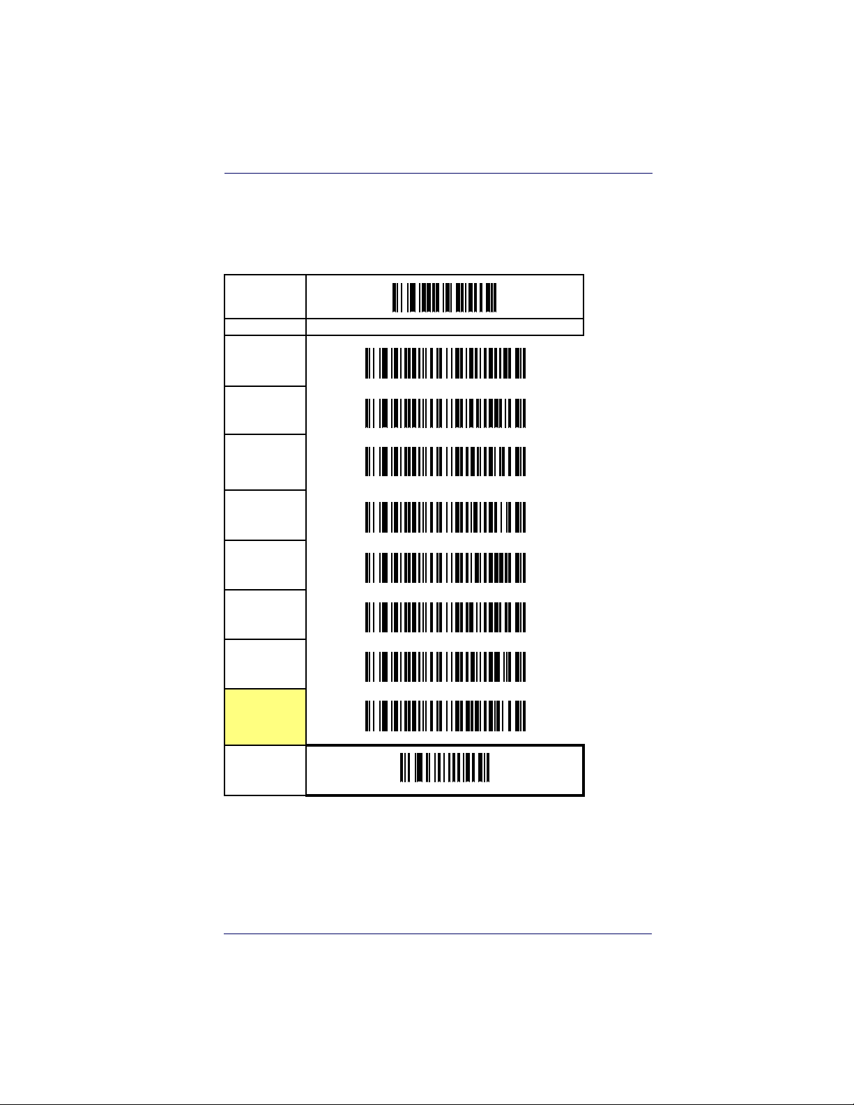
Double Read Timeout
The Double Read Timeout feature sets a time limit that determines how much time
must pass before reading the same label again (e.g. two identical items in succession).
START
DURATION BARCODE
0.1 Second
0.2 Second
0.3 Second
0.4 Second
0.5 Second
0.6 Second
0.7 Second
0.8 Second
Product Reference Guide 3-1
Page 20
General Features
START
DURATION BARCODE
0.9 Second
1 Second
END
3-2 QuickScan® QS6500/QS6500BT
Page 21
Imager Timeout
Imager Timeout
The Imager Timeout feature sets the time for automatically switching the unit off when
the imager is not in use.
START
DURATION BARCODE
1 Second
2 Seconds
3 Seconds
4 Seconds
5 Seconds
6 Seconds
7 Seconds
8 Seconds
9 Seconds
10 Seconds
11 Seconds
12 Seconds
Product Reference Guide 3-3
Page 22
General Features
START
DURATION BARCODE
13 Seconds
14 Seconds
15 Seconds
END
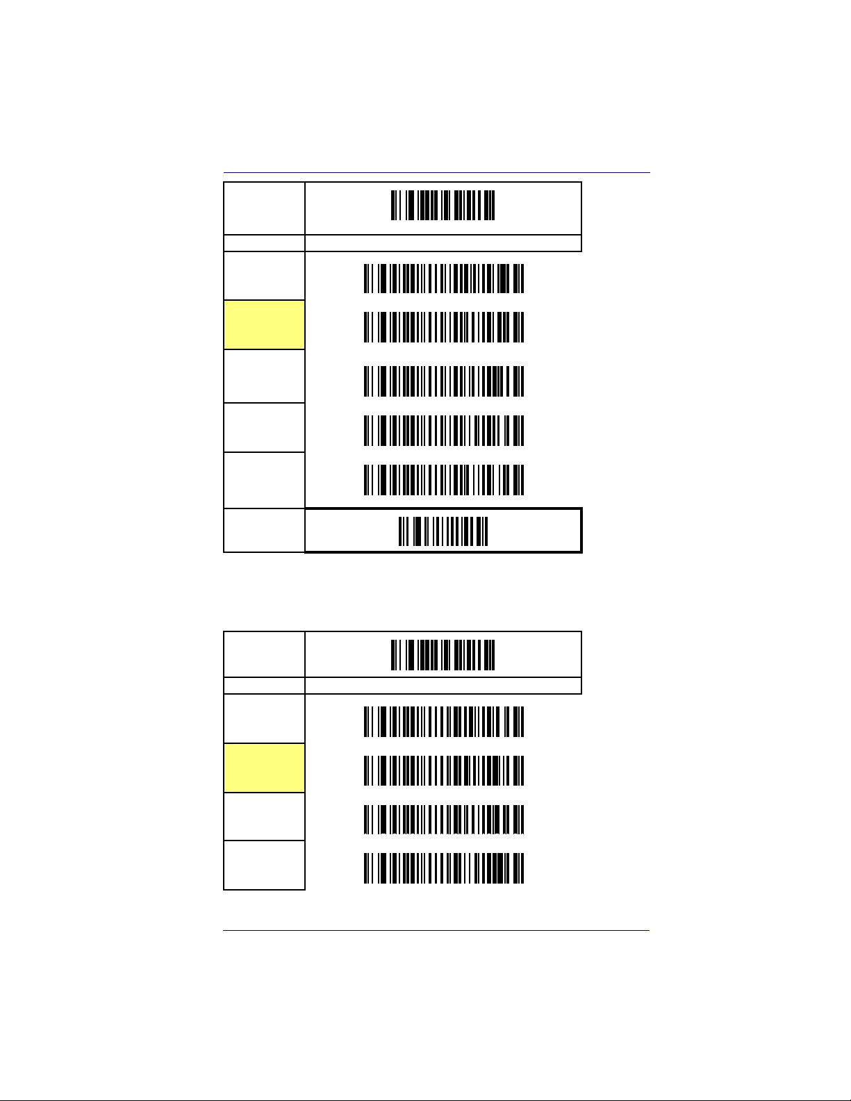
Read Verification
Sets the number of times a bar code must be read before it is transmitted.
START
# of TIMES BARCODE
None
1
2
3
4
5
3-4 QuickScan® QS6500/QS6500BT
Page 23
START
# of TIMES BARCODE
6
7
8
9
END
Read Verification
Product Reference Guide 3-5
Page 24
General Features
LED and Beeper Indicators
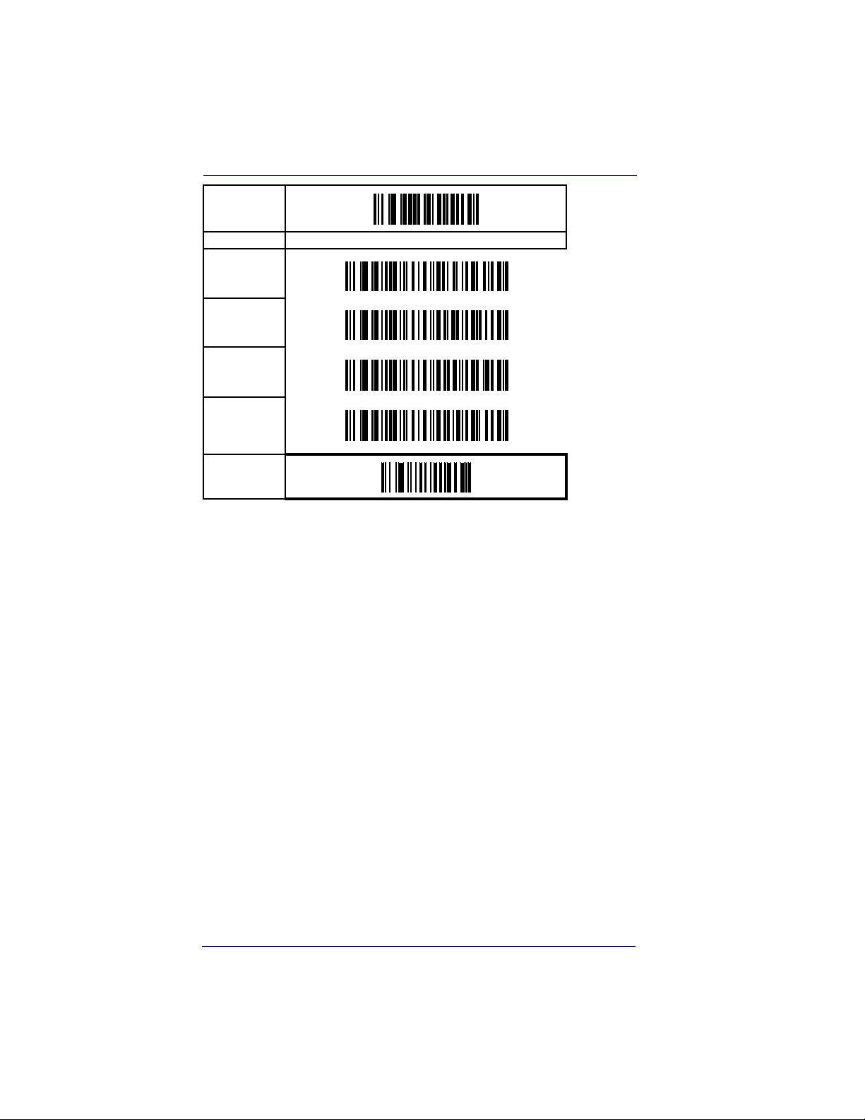
Power On Alert
Disables or enables the indication (LED and/or Beeper) that the imager
is receiving power.
START
STATE BARCODE
Disable
Enable
END
LED Idle State
This feature specifies the state of the green scanner LED when the scanner is idle and ready to read a label. Options are:
• Off
• On dim
START
STATE BARCODE
LED OFF
LED ON
END
3-6 QuickScan® QS6500/QS6500BT
Page 25
LED and Beeper Indicators
Good Read: When to Indicate
This feature specifies when the imager will provide indication (beep and/
or flash its green LED) upon successfully reading a bar code. Choices are:
• Good Read = Indicate after decode
• Good Read = Indicate after transmit
• Good Read = Indicate after CTS goes inactive, then active
This option, which uses CTS, is only valid for RS-232
interfaces.
NOTE
START
INDICATE BARCODE
After decode
After transmit
After CTS goes
inactive, then
active
END
Product Reference Guide 3-7
Page 26
General Features
Good Read Beep Control
This feature enables/disables the imager’s ability to beep upon a successful decode of a label.
START
STATE BARCODE
Disable
Enable
END
Good Read Beep Frequency
Adjusts the good read beep to sound at a selectable low, medium or high
frequency, selectable from the list below. (Controls the beeper’s pitch/
tone.)
START
FREQUENCY BARCODE
2000 Hz
2100 Hz
2200 Hz
2300 Hz
2400 Hz
3-8 QuickScan® QS6500/QS6500BT
Page 27
START
FREQUENCY BARCODE
2500 Hz
2600 Hz
2700 Hz
2800 Hz
2900 Hz
END
LED and Beeper Indicators
Good Read Beep Length
Specifies the duration of a good read beep.
START
LENGTH BARCODE
60msec
80msec
100msec
120msec
Product Reference Guide 3-9
Page 28
General Features
START
LENGTH BARCODE
140msec
160msec
180msec
200msec
END
3-10 QuickScan® QS6500/QS6500BT
Page 29
LED and Beeper Indicators
Good Read Beep Volume
Selects the beeper volume (loudness) upon a good read beep. There are
five selectable volumes, with each volume increment adding approximately five decibels to the previous level.
START
VOLUME BARCODE
Off
Level 1
Level 2
Level 3
Level 4
Level 5
Level 6
Level 7
END
Product Reference Guide 3-11
Page 30

General Features
Scanning/Imaging Features
Scan Mode
Selects the scan operating mode for the imager. Selections are:
• Good read off — The trigger must be pressed to activate scanning.
The light source stops scanning when there is a successful read or
no bar code is decoded after the
• Momentary — The trigger acts as a switch. Pressing the trigger
activates scanning; releasing it stops scanning.
• Alternate — The trigger acts as a toggle switch. Pressing the trigger
activates scanning; pressing it a second time stops scanning
• Timeout off — The trigger must be pressed to activate scanning,
The imager stops scanning if no barcode is decoded within the
time duration set for the
• Stand Mode — The imager continuously reads regardless of
whether the trigger is pressed or ”Imager Timeout” has elapsed.
”Imager Timeout” period.
”Imager Timeout” has elapsed.
3-12 QuickScan® QS6500/QS6500BT
Page 31

Scanning/Imaging Features
Scan Mode — continued
START
MODE BARCODE
Good read off
Momentary
Alternate
Timeout off
Stand mode
END
Product Reference Guide 3-13
Page 32

General Features
Stand Mode LED
When this feature is set to ON while in stand mode, the illumination
LEDs go to a dim state after a timeout of reading no labels. When set to
OFF in stand mode, the illumination LEDs go off after a timeout of
reading no labels. In both cases, the illumination LEDs come back on
when something passes in front of the imager.
START
STATE BARCODE
LED OFF
LED ON
END
Scan Illumination LED Timeout
Limits the time following pressing the trigger that the illumination LED
(aiming light) is lit. Disabling this feature turns the illumination off.
Selecting “Continue” means the imager always keeps reading regardless
of whether the trigger button is pressed or the standby duration has
elapsed.
START
DURATION BARCODE
Disable
30 Seconds
60 Seconds
3-14 QuickScan® QS6500/QS6500BT
Page 33

START
DURATION BARCODE
90 Seconds
120 Seconds
150 Seconds
180 Seconds
Continue
END
Scanning/Imaging Features
Inverted Image Scan
With this option enabled, the imager will scan black/white bar codes
with a white/black background.
START
MODE BARCODE
Disable
Enable
END
Product Reference Guide 3-15
Page 34

General Features
Global Features
Global Minimum Code Length
Global minimum length can be set to qualify data entry. The length is
defined as the actual bar code data length to be sent. bar code labels with
lengths exceeding these limits will be rejected. Ensure that the minimum-length setting is no greater than the maximum-length setting; otherwise, the labels of the symbology will not be readable. In particular,
you can set the same value for both minimum and maximum lengths to
force decoding of only fixed-length bar codes. This setting has no effect
on certain symbologies of fixed length.
START
MODE BARCODE
Global Minimum length can be set from 0 to 255. To
set this feature, scan the “START” bar code above to
place the unit in Programming Mode, then the “Set
Global Minimum Length,” followed by the digits from
the Alphanumeric table in
Numeric Pad representing your desired minimum
length. Accept your selection by scanning the “SET”
bar code below and finally, exit programming mode by
scanning the “END” barcode below.
DEFAULT SETTING FOR THIS FEATURE: 4
Appendix B, Alpha-
Set Global
Minimum
Length
SET
END
3-16 QuickScan® QS6500/QS6500BT
Page 35

Global Features
Global Maximum Code Length
Global maximum length can be set to qualify data entry. The length is
defined as the actual bar code data length to be sent. bar code labels with
lengths exceeding these limits will be rejected. Ensure that the minimum-length setting is no greater than the maximum-length setting; otherwise, the labels of the symbology will not be readable. In particular,
you can set the same value for both minimum and maximum lengths to
force decoding of only fixed-length bar codes. This setting has no effect
on certain symbologies of fixed length.
START
MODE BARCODE
Global Maximum length can be set from 0 to 255. To
set this feature, scan the “START” bar code above to
place the unit in Programming Mode, then the “Set
Global Maximum Length,” followed by the digits from
the Alphanumeric table in
Numeric Pad representing your desired maximum
length. Accept your selection by scanning the “SET”
bar code below and finally, exit programming mode by
scanning the “END” barcode below.
DEFAULT SETTING FOR THIS FEATURE: 64
Appendix B, Alpha-
Set Global
Maximum
Length
SET
END
Product Reference Guide 3-17
³
Page 36

General Features
NOTES
3-18 QuickScan® QS6500/QS6500BT
Page 37

Chapter 4
Interface Related
Features
At the time of this writing, the Imager supports the interfaces listed in
Ta bl e 4 - 1. Select the desired interface type from the table, then reference
the page number given for the customizable features section associated
with each interface. See
Wedge interface type (A through Y as listed).
Ta bl e 4 - 2 for a description of each Keyboard
Product Reference Guide 4-1
Page 38

Interface Related Features
Table 4-1. Interfaces Supported
RS-232 Page Keyboard Wedge Page
RS-232 Standard
RS-232 Wincor-Nixdorf
IBM
IBM 4683 Port 5B
IBM 4683 Port 9B
IBM 4683 Port 17
USB
IBM USB
USB Keyboard
Keyboard Wedge
Keyboard Wedge A
Keyboard Wedge B
Keyboard Wedge C
Keyboard Wedge D
Keyboard Wedge E
Keyboard Wedge F
Keyboard Wedge G
Keyboard Wedge H
a. Consult Table 4-2 for more information regarding keyboard wedge inter-
face types.
a
a
a
a
a
a
a
a
4-9
4-9
Keyboard Wedge I
Keyboard Wedge J
Keyboard Wedge K
4-25
4-25
4-25
Keyboard Wedge L
Keyboard Wedge M
Keyboard Wedge N
Keyboard Wedge O
4-25
4-25
Keyboard Wedge P
Keyboard Wedge Q
Keyboard Wedge R
4-27
4-27
4-27
4-27
4-27
4-27
4-27
Keyboard Wedge S
Keyboard Wedge T
Keyboard Wedge U
Keyboard Wedge V
Keyboard Wedge W
Keyboard Wedge X
Keyboard Wedge Y
4-27 Wand Emulation
a
a
a
a
a
a
a
a
a
a
a
a
a
a
a
a
a
4-27
4-27
4-27
4-27
4-27
4-27
4-27
4-27
4-27
4-27
4-27
4-27
4-27
4-27
4-27
4-27
4-27
4-34
The correct interface cable is included for the imager
interface type you ordered.
NOTE
4-2 QuickScan® QS6500/QS6500 BT
Page 39

Table 4-2. Keyboard Wedge Interface Reference
I/F Type PCs Supported
A PC/XT w/Alternate Key Encoding
AT, PS/2 25-286, 30-286, 50, 50Z, 60, 70, 80, 90 & 95 w/Alternate Key
B
Encoding
C PS/2 25 and 30 w/Alternate Key Encoding
D PC/XT w/Standard Key Encoding
AT, PS/2 25-286, 30-286, 50, 50Z, 60, 70, 80, 90 & 95 w/Standard Key
E
Encoding
F PS/2 25 and 30 w/Standard Key Encoding
G IBM 3xxx w/122 keyboard
H IBM 3xxx w/102 keyboard
I PS/55 5530T w/104 keyboard
J NEC 9801
K WYSE 30/30+ WY-30 Keyboard 83 Keys
WYSE 60/85/99 GT/150/160/285 Style IBM Enhanced PC, 520/520ES
L
Style IBM Enhanced PC FR
WYSE 55/65/65 ES/120/185/325 Style IBM Enhanced PC
WYSE 60/85/99 GT/150/160/285 ANSI Keyboard 105 Keys, 520/520 ES
M
ANSI Keyboard 105 Keys
WYSE 55/65/65 ES/120/185/325 ANSI Keyboard 105 Keys
WYSE 60/85/99 GT/150/160/285 ASCII Kbd, 520/520 ES ASCII Kbd
N
WYSE 55/65/65 ES/120/185/325 ASCII Keyboard
WYSE 60/85/99 GT/150/160/285 ANSI W285 Keyboard 105 Keys, 520/
O
520 ES ANSI W285 Keyboard 105 Keys
WYSE 55/65/65 ES/120/185/325 ANSI W285 Keyboard 105 Keys
P WYSE WINTERM 3320 SE
IBM 3153
Q
IBM 316X, 3179/3180/319X/3270
R IBM 3151/3152-010, 347X/348X
S DIGITAL VT 220/320/330/340/350/382
T DIGITAL VT420
U DIGITAL VT 510/520 IBM ANSI Style Keyboard
V DIGITAL VT 510/520 IBM PC Style Keyboard
W SUN SPARC 5/10
X SUN 420/440, ITX
Y WYSE 370/355 Style Enhanced IBM PC
Reference
pings
Appendix C, Keyboard Function Key Map-
for more information about keyboards.
NOTE
Product Reference Guide 4-3
Page 40

Interface Related Features
Interface Selection
START
STATE BARCODE
RS-232
Standard
RS-232
Wincor-Nixdorf
IBM 4683
Por t 5B
IBM 4683
Por t 9B
IBM 4683
Por t 17
IBM USB
USB Keyboard
Keyboard
Wedge A
Keyboard
Wedge B
Keyboard
Wedge C
4-4 QuickScan® QS6500/QS6500 BT
Page 41

START
STATE BARCODE
Keyboard
Wedge D
Keyboard
Wedge E
Keyboard
Wedge F
Keyboard
Wedge G
Keyboard
Wedge H
Interface Selection
Keyboard
Wedge I
Keyboard
Wedge J
Keyboard
Wedge K
Keyboard
Wedge L
Keyboard
Wedge M
Keyboard
Wedge N
Product Reference Guide 4-5
Page 42

Interface Related Features
START
STATE BARCODE
Keyboard
Wedge O
Keyboard
Wedge P
Keyboard
Wedge Q
Keyboard
Wedge R
Keyboard
Wedge S
Keyboard
Wedge T
Keyboard
Wedge U
Keyboard
Wedge V
Keyboard
Wedge W
Keyboard
Wedge X
4-6 QuickScan® QS6500/QS6500 BT
Page 43

START
STATE BARCODE
Keyboard
Wedge Y
Wand
Emulation
END
Interface Selection
Product Reference Guide 4-7
Page 44

Interface Related Features
Interface Features
Global Interface Features
START
STATE BARCODE
Obey Host
Commands
Ignore Host
Commands
Disable Debug
Mode
Enable Debug
Mode
Host
Transmission
Buffers = 1
Host
Transmissioin
Buffers = 2
END
4-8 QuickScan® QS6500/QS6500 BT
Page 45

RS-232 Interface Features
START
STATE BARCODE
1200 Baud
2400 Baud
4800 Baud
9600 Baud
19200 Baud
38400 Baud
Interface Features
57600 Baud
115200 Baud
Product Reference Guide 4-9
Page 46

Interface Related Features
RS-232 Interface Features — cont.
START
STATE BARCODE
7 Data Bits
8 Data Bits
1 Stop Bit
2 Stop Bits
Parity = None
Parity = Even
Parity = Odd
END
4-10 QuickScan® QS6500/QS6500 BT
Page 47

Interface Features
RS-232 Interface Features — cont.
Hardware Flow Control
Disable Hardware Control —
any activity on the CTS line.
Enable CTS Flow Control —
to the host.
Enable CTS Scan Control —
read and transmit data. While the CTS line is inactive, the imager
remains in a host-disabled state; following a successful label transmission, the CTS signal must transition to inactive and then to active to
enable scanning for the next label.
The imager transmits to the host regardless of
The CTS signal controls transmission of data
The CTS line must be active for the imager to
Intercharacter Delay
This delay is inserted after each data character transmitted. If the transmission speed is too high, the system may not be able to receive all characters. You may need to adjust the delay to make the system work
properly.
Software Flow Control
Disables/Enables software control using XON/XOFF characters.
Product Reference Guide 4-11
Page 48

Interface Related Features
RS-232 Interface Features — cont.
START
STATE BARCODE
Disable
Hardware
Control
Enable CTS
Flow Control
Enable CTS
Scan Control
Inter-Char
Delay = No
Delay
Interchar Delay
= 10 msec
Interchar Delay
= 20 msec
Interchar Delay
= 30 msec
Interchar Delay
= 40 msec
Interchar Delay
= 50 msec
Interchar Delay
= 60 msec
Interchar Delay
= 70 msec
Interchar Delay
= 80 msec
Interchar Delay
= 90 msec
4-12 QuickScan® QS6500/QS6500 BT
Page 49

Interface Features
RS-232 Interface Features — cont.
START
STATE BARCODE
Disable
Software Flow
Control
Enable
Software Flow
Control
END
Product Reference Guide 4-13
Page 50

Interface Related Features
RS-232 Interface Features — cont.
Host Echo
When enabled, this feature passes all data through the imager to the host
as it comes in. This feature is used for applications where “daisy chaining” of RS-232 devices onto the same cable is necessary. If, for example,
one of the devices in the chain is a terminal where someone is entering
data while another person is simultaneously scanning a bar code requiring transmission to the host, the scanner will wait for the RS-232 channel to be quiet for a specified period of time (set via
Quiet Interval
ing its data in order to avoid RS-232 transmission conflicts.
). The scanner can be set to observe this delay before send-
Host Echo Quiet Interval
This setting specifies the time interval of RS-232 channel inactivity
which must transpire before the imager will break the host echo loop to
transmit the bar code data that has just been scanned to the host.
Signal Voltage: Normal/TTL
RS-232 Host Echo
Specifies whether the RS-232 interface provides TTL levels on the output pins TxD and RTS.
RS-232 Invert
Enables/disables inversion of RS-232 TXD and RXD signals.
4-14 QuickScan® QS6500/QS6500 BT
Page 51

Interface Features
RS-232 Interface Features — cont.
START
STATE BARCODE
Disable Host
Echo
Enable Host
Echo
Host Echo
Quiet Interval
= 0msec
Host Echo
Quiet Interval
= 10msec
Host Echo
Quiet Interval
= 20msec
Host Echo
Quiet Interval
= 30msec
Host Echo
Quiet Interval
= 40msec
Host Echo
Quiet Interval
= 50msec
Host Echo
Quiet Interval
= 60msec
Host Echo
Quiet Interval
= 70msec
Host Echo
Quiet Interval
=80msec
Host Echo
Quiet Interval
= 90msec
Product Reference Guide 4-15
Page 52

Interface Related Features
RS-232 Interface Features — cont.
START
STATE BARCODE
Host Echo
Quiet Interval
= 100msec
Signal
Voltag e:
Normal RS-232
Signal Voltage:
TTL
No TTL
Inversion
Invert TTL
END
Beep on ASCII BEL
Enables/disables ability of imager to beep (sound a good read tone) on
receiving an ASCII BEL (07 hex).
Beep on Not on File
Select for the host to beep (or not) when a not-on-file (host command)
condition is detected by the host.
ACK NAK Options
This enables/disables the ability of the imager to support the RS-232
ACK/NAK protocol. When configured, the imager and/or host sends an
“ACK” when it receives data properly, and sends “NAK” when the data is
in error. Selections for this option are:
•Disable
4-16 QuickScan® QS6500/QS6500 BT
Page 53

Interface Features
• Enable for label transmission — the imager expects an ACK/NAK
response from the host when a label is sent
• Enable for host-command acknowledge — the imager will
respond with ACK/NAK when the host sends a command
• Enable for label transmission and host-command acknowledge
START
STATE BARCODE
Disable Beep
on ASCII BEL
Enable Beep on
ASCII BEL
Disable Beep
on Not On File
Enable Beep
on Not On File
Disable ACK
NAK
Enable ACK
NAK for
Transmission
Enable ACK
NAK for host-
command
acknowledge
Enable ACK
NAK for trans-
mission and
host-command
END
Product Reference Guide 4-17
Page 54

Interface Related Features
RS-232 Interface Features — cont.
ACK Character
START
MODE BARCODE
Sets the ACK character from the set of ASCII characters or any hex value from 0 to FF. To configure this
feature, scan the “START” bar code above to place
the unit in Programming Mode, then the “Set ACK
Character,” followed by the digits from the Alphanumeric table in
representing your desired character. Accept your
selection by scanning the “SET” bar code below and
finally, exit programming mode by scanning the
“END” barcode below.
DEFAULT SETTING FOR THIS FEATURE: 06 (0x06)
Set ACK
Character
Appendix B, Alpha-Numeric Pad
SET
END
4-18 QuickScan® QS6500/QS6500 BT
Page 55

Interface Features
RS-232 Interface Features — cont.
NAK Character
START
MODE BARCODE
Sets the NAK character from the set of ASCII characters or any hex value from 0 to FF. To configure this
feature, scan the “START” bar code above to place
the unit in Programming Mode, then the “Set NAK
Character,” followed by the digits from the Alphanumeric table in
representing your desired character. Accept your
selection by scanning the “SET” bar code below and
finally, exit programming mode by scanning the
“END” barcode below.
DEFAULT SETTING FOR THIS FEATURE: 21 (0x15)
Set NAK
Character
Appendix B, Alpha-Numeric Pad
SET
END
Product Reference Guide 4-19
Page 56

Interface Related Features
RS-232 Interface Features — cont.
Retry on ACK NAK Timeout
Enables/disables retry after the configurable ACK NAK Timeout Value
(set in the following feature) has expired.
START
STATE BARCODE
Disable Retry
on ACK NAK
Timeout
Enable Retry
on ACK NAK
Timeout
END
4-20 QuickScan® QS6500/QS6500 BT
Page 57

Interface Features
RS-232 Interface Features — cont.
ACK NAK Timeout Value
START
MODE BARCODE
This item specifies the time the imager will wait for an
ACK character from the host following a label transmission.
0 = Infinite timeout
1 - 75 = Timeout in 200-millisecond increments
To configure this feature, scan the “START” bar code
above to place the unit in Programming Mode, then
the “Set ACK NAK Timeout Value,” followed by the
digits from the Alphanumeric table in
Alpha-Numeric Pad
value. Accept your selection by scanning the “SET”
bar code below and finally, exit programming mode
by scanning the “END” barcode below
DEFAULT SETTING FOR THIS FEATURE: 01
representing your desired
Appendix B,
Set ACK
NAK Timeout
Val ue
SET
END
Product Reference Guide 4-21
Page 58

Interface Related Features
RS-232 Interface Features — cont.
ACK NAK Retry Count
START
MODE BARCODE
This feature sets the number of times for the imager
to retry a label transmission under a retry condition.
0 = No retry
1 - 254 = Retry for the specified number of times
255 = Retry forever
To configure this feature, scan the “START” bar code
above to place the unit in Programming Mode, then
the “Set ACK NAK Retry Count,” followed by the digits from the Alphanumeric table in
Alpha-Numeric Pad
count. Accept your selection by scanning the “SET”
bar code below and finally, exit programming mode
by scanning the “END” barcode below
DEFAULT SETTING FOR THIS FEATURE: 03
representing your desired retry
Appendix B,
Set ACK
Nak Retry
Count
SET
END
4-22 QuickScan® QS6500/QS6500 BT
Page 59

Interface Features
RS-232 Interface Features — cont.
ACK NAK Error Handling
This item specifies the method the imager will use to handle errors
detected while waiting to receive the ACK character from the host.
Errors include unrecognized host commands and communication errors
such as parity or framing errors. Choices are:
00 = Ignore errors detected (recommended setting)
01 = Process error as valid ACK character (risk of lost label data)
02 = Process error as valid NAK character (risk of duplicate label data)
START
STATE BARCODE
Ignore Errors
Detected
Process error
as valid ACK
character
Process error
as valid NAK
character
END
Product Reference Guide 4-23
Page 60

Interface Related Features
RS-232 Interface Features — cont.
Transmission Failure Indication
Enables/disables bad-label indication upon transmission failure.
START
STATE BARCODE
Disable
Transmission
Error Indication
Enable
Transmission
Error
Indication
END
4-24 QuickScan® QS6500/QS6500 BT
Page 61

Interface Features
IBM-USB Interface Features
IBM-USB Device usage
The IBM-USB protocol allows for the imager to be identified as one of
two different types of bar code scanners. Depending on what other scanners you may already have connected to a IBM-USB POS, you may need
to change this setting to enable all devices to communicate. Options are:
• Table Top Scanner
• Handheld Scanner
START
STATE BARCODE
Configure as
Tab l e To p
Scanner
Configure as
Handheld
Scanner
END
Product Reference Guide 4-25
Page 62

Interface Related Features
IBM
IBM Transmit Labels in Code 39 Format
This feature enables/disables imager's ability to set a symbology
identifier for a specified label to Code 39 before transmitting
that label data to an IBM host. This applies to: Code 128, Codabar, and Code 93 for IBM USB; Code 128, Codabar, and Code
93 for IBM Port 5B; and Codabar and Code 93 for IBM Port
9B.
START
STATE BARCODE
Disable
Convert to
Code 39
Enable Convert
to Code 39
END
4-26 QuickScan® QS6500/QS6500 BT
Page 63

Interface Features
Keyboard Wedge/USB Keyboard
As a keyboard interface, the imager supports most popular PCs and IBM
terminals. The installation of the wedge is a fairly simple process that
doesn’t require any changes of software or hardware.
All of the options in this section apply to the Keyboard Wedge, however, only
Lock State
NOTE
Keyboard Layout
board.
and Control Characters apply to USB Key-
The Keyboard Layout option supports many countries. For details about
Keyboard Layout, please refer to your operating system manual.
START
STATE BARCODE
USA
Keyboard Layout, Caps
Belgium
Britain
Denmark
France
Germany
Italy
Norway
Product Reference Guide 4-27
Page 64

Interface Related Features
START
STATE BARCODE
Portugal
Spain
Sweden
Switzerland
Japan 106 Key
Hungary
Czech
Slovakia
Romania
END
4-28 QuickScan® QS6500/QS6500 BT
Page 65

Interface Features
Keyboard Wedge/USB Keyboard — cont.
Caps Lock State
Specifies which format the imager sends character data.
START
STATE BARCODE
Disable Caps
Lock
Caps Lock “ON”
Shift Lock “ON”
END
Product Reference Guide 4-29
Page 66

Interface Related Features
Keyboard Wedge/USB Keyboard — cont.
Power-On Simulation
This feature does not apply to the USB Keyboard
interface.
NOTE
All PCs check the keyboard status during the power-on Selftest. It is recommended that you enable this function if you are working without a
keyboard installation. It simulates keyboard timing and passes the keyboard status to the PC during power-on.
Control Characters
Specifies how the imager transmits ASCII control characters to the host.
Choices are:
• Disable Control Characters
• Enable transmission of control characters to host
• Send characters between 00H and 1FH according to a special
function-key mapping table. (This is used to send keys that are not
in the normal ASCII set; a unique set is provided for each available
scancode set. Reference
pings
.)
Appendix C, Keyboard Function Key Map-
4-30 QuickScan® QS6500/QS6500 BT
Page 67

Interface Features
Keyboard Wedge/USB Keyboard — cont.
START
STATE BARCODE
Disable
Power-on
Simulation
Enable
Power-on
Simulation
Disable
Control
Characters
Enable
Transmission of
Control
Characters
Enable
Function Key
Mapping
END
Product Reference Guide 4-31
Page 68

Interface Related Features
Keyboard Wedge/USB Keyboard — cont.
Wedge Quiet Interval
This feature does not apply to the USB Keyboard
interface.
NOTE
Quiet Interval is the amount of time to look for keyboard activity before
the imager breaks the keyboard connection in order to transmit data to
the host..
START
MODE BARCODE
Selectable from 00 (no interval) to 255 in 10 msec
increments. Use hexidecimal (range: 00 to FF hexidecimal) to set the interval. To configure this feature, scan
the “START” bar code above to place the unit in Programming Mode, then the
bar code followed by the digits from the Alphanumeric
Appendix B, Alpha-Numeric Pad represent-
table in
ing your desired length. Accept your selection by scanning the “SET” bar code below and finally, exit
programming mode by scanning the “END” barcode
below
DEFAULT SETTING FOR THIS FEATURE:
Set Wedge Quiet Interval
01 (10 msec)
Set Wedge
Quiet Interval
SET
END
4-32 QuickScan® QS6500/QS6500 BT
Page 69

Interface Features
Keyboard Wedge/USB Keyboard — cont.
Intercharacter Delay
This feature does not apply to the USB Keyboard
interface.
NOTE
START
MODE BARCODE
This delay is inserted after each data character transmitted. If the transmission speed is too high, the system may not be able to receive all characters. You may
need to adjust the delay to make the system work properly. Selectable from 00 to 255 in 10msec increments.
Use hexidecimal (range: 00 to FF hexidecimal) to set
the delay.
To configure this feature, scan the “START” bar code
above to place the unit in Programming Mode, then the
“Set Intercharacter Delay,” followed by the digits from
the Alphanumeric table in
Numeric Pad
Accept your selection by scanning the “SET” bar code
below and finally, exit programming mode by scanning
the “END” barcode below
DEFAULT SETTING FOR THIS FEATURE:
representing your desired length.
Appendix B, Alpha-
00 (No Delay)
Set
Intercharacter
Delay
SET
END
Product Reference Guide 4-33
Page 70

Interface Related Features
Wand Emulation
Supported Symbologies
The Wand Emulation interface will transmit bar code data as a wand
device would. This interface will transmit the following bar code symbologies:
•UPC/EAN
•UPC/EAN with addons
•Code 39
• Full ASCII Code 39
• Interleaved 2 of 5
• Codabar
• Code 128
All other bar code symbology types read by the scanner will be transmitted as Code 128.
Wand Emulation Bar Code Format
The following format settings are required for the wand emulation interface. These settings have been pre-configured at the factory for Wand
Emulation scanners.
• UPC-A bar codes must include all 12 digits.
• UPC-E bar codes must contain 8 digits, including a system digit, 6
data digits, and the check digit.
• EAN-13 bar codes must have all 13 digits.
• EAN-8 bar codes must include all 8 digits.
• Code 39, Code 39 Full ASCII, and Pharmacode 39 bar codes must
NOT contain start / stop characters.
• Codabar bar codes must include the start / stop characters, presented in the ABCD format.
• Interleaved 2 of 5 bar codes must have an even number of digits.
• The Prefix, Suffix, and Code ID must be disabled for all symbologies
4-34 QuickScan® QS6500/QS6500 BT
Page 71

Interface Features
Wand Emulation — cont.
Bar/Space Polarity
Low/High — Black will be transmitted as a low voltage level (0V) and
space as high level (+5).
High/Low — Black will be transmitted as a high voltage level (+5) and
space as low level (0V).
Initial Polarity
The idle polarity of the wand decode device can be set with the following
options:
High voltage level (+5)
Low voltage level (0V).
START
STATE BARCODE
Bar/Space =
Low/High
Bar/Space =
High/Low
Initial Polarity
= High Voltage
(+5V)
Initial Polarity =
Low Voltage
(0V)
END
Product Reference Guide 4-35
Page 72

Interface Related Features
Wand Emulation — cont.
Signal Speed
The speed of the transmission can be set. This selects the width of the
minimum narrow bar.
330 microseconds
660 microseconds
Transmit Trailing Noise
The transmission of noise pulses after the label may be enabled or disabled.
START
STATE BARCODE
Signal Speed =
330mS
Signal Speed =
660mS
Disable
Trailing Noise
Enable Trailing
Noise
END
4-36 QuickScan® QS6500/QS6500 BT
Page 73

Interface Features
Wand Emulation — cont.
Transmit Leading Noise
The transmission of noise pulses before the bar code may be enabled or
disabled.
Symbology Conversion
Wand Emulation can convert all bar codes to a single symbology.
Choices are:
No Conversion
Convert to Code 39 / Code 39 Full ASCII
Convert to Code 128
START
STATE BARCODE
Disable
Leading Noise
Enable
Leading Noise
No Symbology
Conversion
Convert to C39/
C39 Full ASCII
Convert to
C128
END
Product Reference Guide 4-37
Page 74

Interface Related Features
NOTES
4-38 QuickScan® QS6500/QS6500 BT
Page 75

Chapter 5
Data Editing
Data Editing Overview
It is not recommended to use these features with IBM
46xx or IBM interfaces.
CAUTION
When a bar code is scanned, additional information can be sent to the
host computer along with the bar code data. This combination of bar
code data and supplementary user-defined data is called a “message
string.” The features in this chapter can be used to build specific
user-defined data into a message string.
There are several types of selectable data characters that can be sent
before, after, and even between scanned data. You can specify if they
should be sent with all symbologies, or only with specific symbologies.
Figure 5-1 shows the available elements you can add to a message string:
Figure 5-1. Breakdown of a Message String
Code Length Transmission: A number of data
digits can be transmitted before the code data.
The total length of the bar code is the number
of characters of bar code data without truncated
leading or ending digits.
Prefix
Code ID Transmission: Enable
this option to transmit the code
ID. See page ?.
Symbology Name: This function is used to identify and display the
scanned bar code's symbology (from among any of the symbologies
readable by the imager). When enabled, the code name
(symbology) will be transmitted before the bar code data.
Product Reference Guide 5-1
00 - 22 Characters (ASCII)
00 - 22 Characters (ASCII)
Data Groups 1, 2, 3 and 4: Can be
variably inserted into positions within the
bar code data itself. One ASCII character
per Data Group, with character
selectable from 00 (none) to 63.
Insert Groups
SufffixSymbology ID IDPreamble PostambleBar Code DataCode Length
Page 76

Data Editing
Please Keep In Mind...
• Modifying a message string is not a mandatory requirement. Data
editing is sophisticated feature allowing highly customizable output for advanced users. Factory default settings for data editing is
typically set to NONE.
• A prefix or suffix may be applied to one symbology (reference the
Symbologies chapter for these settings) or across all symbologies
(set via the features in this chapter).
• You can add any prefix or suffix from
, plus Code I.D/AIM I.D.
Chart
Appendix A, ASCII Conversion
• Several entries for several symbologies can be strung together at
one time.
• Enter prefixes and suffixes in the order in which you want them to
appear on the output.
Prefix/Suffix
Up to 22 ASCII characters may be added as a prefix (in a position before
the bar code data) and/or as a suffix (in a position following the bar code
data) as indicated in
Figure 5-2. Prefix and Suffix Positions
Prefix Symbology
Figure 5-2.
Insert Groups
SufffixID IDPreamble PostambleBar Code DataCode Length
00 - 22 Characters (ASCII)
5-2 QuickScan® QS6500/QS6500 BT
Page 77

Data Editing Overview
Prefix/Suffix — continued
Example: Setting a Prefix
In this example, we’ll set a prefix for all symbologies.
1. Determine which ASCII character(s) are to be added to scanned
bar code data. In this example, we’ll add a dollar sign (‘$’) as a prefix.
2. Scan the START bar code.
3. Scan the SET PREFIX CHARACTER(S) bar code.
4. Reference
Appendix A, ASCII Conversion Chart, to find the hex value
assigned to the desired character. The corresponding hex number
for the ‘$’ character is 24. To enter this selection code, scan the ‘2’
and ‘4’ bar codes from
Appendix B, Alpha-Numeric Pad.
5. Scan the SET bar code to accept the digits scanned.
6. Scan the END bar code to exit Programming Mode.
7. The resulting message string would appear as follows:
Scanned bar code data: 12345
Resulting message string output: $12345
Product Reference Guide 5-3
Page 78

Data Editing
Prefix/Suffix — continued
START
MODE BARCODE
Sets up to 22 characters each from the set of ASCII
characters or any hex value from 0 to FF. To configure this feature, scan the “START” bar code above to
place the unit in Programming Mode, then the “Set
Prefix” or “Set Suffix,” followed by the digits from the
Appendix B, Alpha-Numeric
Example: Setting a Prefix, for
Set Prefix
Set Suffix
Alphanumeric table in
Pad
representing your desired character(s). Reference the section,
more information. Accept your selection by scanning
the “SET” bar code below and finally, exit programming mode by scanning the “END” barcode below.
DEFAULT SETTING FOR THIS FEATURE: 00 (None)
SET
END
5-4 QuickScan® QS6500/QS6500 BT
Page 79

Data Editing Overview
Preamble/Postamble
Similar to the Prefix/Suffix, up to 22 ASCII characters may be added as a
preamble (in a position before the bar code data) and/or as a postamble
(in a position following the bar code data) as indicated in
Figure 5-3. Preamble and Postamble Positions
Figure 5-3.
Insert Groups
Prefix
00 - 22 Characters (ASCII)
Example: Setting a Postamble
SufffixSymbology ID IDPreamble PostambleBar Code DataCode Length
In this example, we’ll set a postamble for all symbologies.
1. Determine which ASCII character(s) are to be added to scanned
bar code data. In this example, we’ll add the percent character
(‘%’) as a postamble.
2. Scan the START bar code.
3. Scan the SET POSTAMBLE CHARACTER(S) bar code.
4. Reference
Appendix A, ASCII Conversion Chart, to find the hex value
assigned to the desired character. The corresponding hex number
for the ‘%’ character is 25. To enter this selection code, scan the ‘2’
and ‘5’ bar codes from
Appendix B, Alpha-Numeric Pad.
5. Scan the SET bar code to accept the digits scanned.
6. Scan the TRANSMIT POSTAMBLE bar code to allow transmission of the postamble.
7. Scan the END bar code to exit Programming Mode.
8. The resulting message string would appear as follows:
Scanned bar code data: 12345
Resulting message string output: 12345%
Product Reference Guide 5-5
Page 80

Data Editing
Preamble/Postamble — continued
START
MODE BARCODE
Sets up to 22 characters each from the set of ASCII
characters or any hex value from 0 to FF. To configure this feature, scan the “START” bar code above to
place the unit in Programming Mode, then the “SET
PREAMBLE” or “SET POSTAMBLE,” followed by the
Set Preamble
digits from the Alphanumeric table in
Alpha-Numeric Pad
representing your desired
character(s). Reference the section,
ting a Postamble
, for more information. Accept your
selection by scanning the “SET” bar code below,
scan the “TRANSMIT PREAMBLE” (or “TRANSMIT
POSTAMBLE” as applicable) bar code, then finally,
exit programming mode by scanning the “END” barcode below.
DEFAULT SETTING FOR THIS FEATURE: 00 (None)
Appendix B,
Example: Set-
Disable
Preamble
Transmit
Preamble
Set Postamble
Disable
Postamble
5-6 QuickScan® QS6500/QS6500 BT
Page 81

START
MODE BARCODE
Transmit
Postamble
SET
END
Data Editing Overview
Product Reference Guide 5-7
Page 82

Data Editing
Symbology, I.D. and Code Length
Useful information, such as the scanned bar code’s symbology type, code
I.D. and character length can all be variously added to the message
string. The following are descriptions for each of these elements:
Symbology —
This function is used to identify and display the
scanned bar code's symbology name (from among any of the symbologies readable by the imager). When enabled, the code name (symbology)
will be transmitted in a position before the bar code data.
Code I.D. —
The Code I.D. is an alpha-numeric code representing the
bar code (symbology) type. It can be appended previous to and/or following the transmitted bar code data depending upon how this feature is
enabled.
An extra step is required in enabling this feature. Selection of Code I.D. Positon (either before or after bar code
data) must be made PRIOR to selecting either Propri-
NOTE
etary or AIM I.D.
In addition to message string positioning (before or after bar code data),
options for this feature include:
•Disable
• Proprietary I.D. — Symbologies are identified by an associated
alpha-numeric code developed by the manufacturer.
• AIM I.D. — Symbologies are identified by a standardized alphanumeric code list established by AIM (Association for Automatic
Identification and Mobility).
Code Length —
When enabled, this feature will calculate the total
character length of the scanned bar code (minus truncated leading or
ending digits) and transmit this information just previous to the actual
scanned data.
5-8 QuickScan® QS6500/QS6500 BT
Page 83

Figure 5-4. Code Data Elements
Code Length Transmission: A number of data
digits can be transmitted before the code data.
The total length of the bar code is the number
of characters of bar code data without truncated
leading or ending digits.
Prefix SufffixSymbology ID IDPreamble PostambleBar Code DataCode Length
Code ID Transmission: Enable this
option to transmit the code ID.
Symbology Name: This function is used to identify and display the
scanned bar code's symbology (from among any of the symbologies
readable by the imager). When enabled, the code name
(symbology) will be transmitted before the bar code data.
AND
OR
Data Editing Overview
Product Reference Guide 5-9
Page 84

Data Editing
Symbology, I.D. and Code Length — continued
START
MODE BARCODE
Disable
Symbology
Name
Enable
Symbology
Name
Code I.D.
Position:
Before Bar
Code Data
Code I.D.
Position: After
Bar Code Data
Code I.D.
Transmission:
Disable
Code I.D.
Transmission:
Proprietary
I.D.
Code I.D.
Transmission:
AIM I.D.
Disable Code
Length
Transmission
Enable Code
Length
Transmission
END
5-10 QuickScan® QS6500/QS6500 BT
Page 85

Data Editing Overview
Data Group Characters
Options are available to insert characters in up to four positions between
the scanned bar code data. This is accomplished by selecting the position
and up to 22 ASCII characters for each for Data Group 1, Data Group
2, Data Group 3 and Data Group 4 settings.
The options in this chapter set Data Group Characters
globally for all symbologies. If you wish to enable this
feature only for a single symbology, turn to the options
NOTE
Example: Setting Position and Characters for Data Group 1
for that symbology in the
In this example, we’ll set a positon and select two characters for Data
Group 1.
Select Data Group 1 Position
1. Determine which position in the bar code data you wish to insert
character(s). In this example, we’ll select a position three characters
from the left within the bar code data.
Make sure the insertion position you select is not
greater than the total number of bar code characters
scanned; otherwise, the Data Group character(s) will
NOTE
not be inserted.
Symbologies chapter.
2. Scan the START bar code.
3. Scan the SET DATA GROUP 1 POSITION bar code.
4. In this step, we select the three-spaces-from-the-left position in
which to place the characters we’ll select later. Scan first the 0
(zero) bar code, then the 3 bar code from the numeric digit bar
codes provided in
Appendix B, Alpha-Numeric Pad.
5. Scan the SET bar code to accept the digits scanned.
6. Scan the END bar code to exit Programming Mode.
Select Data Group 1 Character(s)
1. Determine which ASCII character(s) is/are to be added to scanned
bar code data. In this example, we’ll add two characters: + (the plus
sign) and # (the pound, or number sign).
Product Reference Guide 5-11
Page 86

Data Editing
2. Scan the START bar code.
3. Next, scan the SET DATA GROUP 1 CHARACTER bar code.
4. Reference
Appendix A, ASCII Conversion Chart, to find the hex value
assigned to each desired character. The corresponding hex number
for the ‘+’ character is 2B; for the ‘#’ sign, the hex equivalent is 23.
To enter the selection code, scan first the ‘2’ and ‘B’ bar codes from
Appendix B, Alpha-Numeric Pad, then the ‘2’ and ‘3’ bar codes.
5. Scan the SET bar code to accept the digits scanned.
6. Scan the END bar code to exit Programming Mode.
7. Data Group Characters are configured individually for each symbology type, enabling or disabling the Data Groups you’ve created
using the options provided in the
Symbologies chapter.
The resulting message string after completing the steps above would
appear as follows:
Scanned bar code data: 12345
Resulting message string output: 12+#345
Data Group Characters — continued
START
MODE BARCODE
Sets position and up to 22 ASCII characters each or
any hex value from 0 to 64. To configure this feature,
reference the section,
and Characters for Data Group 1
mation.
DEFAULT SETTING FOR THIS FEATURE: 00 (None)
Example: Setting Position
for more infor-
Set Group 1
Positio n
Set Group 1
Character(s)
Set Group 2
Positio n
5-12 QuickScan® QS6500/QS6500 BT
Page 87

Data Editing Overview
Data Group Characters — continued
START
MODE BARCODE
Set Group 2
Character(s)
Set Group 3
Positio n
Set Group 3
Character(s)
Set Group 4
Positio n
Set Group 4
Character(s)
SET
END
Product Reference Guide 5-13
Page 88

Data Editing
Case Conversion
This feature can convert scanned bar code data to either all lower case or
all upper case characters.
Case conversion affects ONLY scanned bar code data,
and does not affect Code I.D., Preamble, Postamble, or
other appended data.
NOTE
START
MODE BARCODE
Disable
Convert to
Upper Case
Convert to
Lower Case
END
5-14 QuickScan® QS6500/QS6500 BT
Page 89

Chapter 6
Symbologies
The imager supports the following symbologies (bar code types).
Options for each symbology are included in this chapter.
·UPC-A ·Interleaved 2 of 5
·UPC-E ·Industrial 2 of 5
·EAN-13 ·Matrix 2 of 5 (Eur)
·EAN-8 ·Codabar
·GTIN ·Code 93
·RSS-14 ·Code 11
·RSS Expanded ·MSI/Plessey
·RSS Limited ·UK-Plessey
·Code 39 ·Te l e pe n
·Pharmacode 39 ·Standard 2 of 5
·Code 128 ·Code 16K
·EAN-128 ·China Post
The PDF417 version of the imager will additionally support these symbologies.:
·PDF 417 ·EAN UCC Composite
·Micro PDF 417
Factory Defaults —
with yellow throughout this section.
Product Reference Guide 6-1
are indicated in bold text and are highlighted
Page 90

Symbologies
UPC-A
The following options apply to the UPC-A symbology.
Disable/Enable UPC-A
When disabled, the imager will not read UPC-A bar codes.
Checksum Transmission
Enable this option to transmit the checksum along with UPC-A bar
code data.
Expand UPC-A to EAN-13
Enable this option to add a leading zero to a UPC-A bar code which
‘expands’ the data to the EAN-13 data format. Selecting this feature also
changes the symbology ID to match those required for EAN-13.
6-2 QuickScan® QS6500/QS6500 BT
Page 91

UPC-A — continued
START
STATE BARCODE
Disable UPC-A
Enable UPC-A
Don’t Send
Checksum
Send
Checksum
No Expansion
Expand UPC-A
to EAN-13
UPC-A
END
Product Reference Guide 6-3
Page 92

Symbologies
UPC-A — continued
Truncate Leading/Ending
The leading or ending digits of bar code data characters can be truncated. Select from 00 (no truncation) to 15.
The imager will beep instead of reading anything when
the truncate value is more than the bar code data digits
or the truncate leading value overlaps the truncate end-
NOTE
START
MODE BARCODE
Sets from 00 to 15 characters to truncate from either the leading or
ending characters of scanned bar code data. To configure this feature, scan the “START” bar code above to place the unit in Programming Mode, then the SET TRUNCATION: LEADING or SET
TRUNCATION: ENDING, followed by the digits from the Alphanumeric table in
desired quantity of digits to trumcate from the message string. Accept
your selection by scanning the “SET” bar code below and finally, exit
programming mode by scanning the “END” barcode below.
DEFAULT SETTING FOR THIS FEATURE: 00 (None)
ing value.
Appendix B, Alpha-Numeric Pad representing the
Set Truncation:
Leading
Set Truncation:
Ending
SET
END
6-4 QuickScan® QS6500/QS6500 BT
Page 93

UPC-A
UPC-A — continued
Code I.D. Selection
The Code I.D. for this symbology consists of one or two user-selectable
ASCII characters. It can be appended previous to or following the transmitted UPC-A bar code data depending on how this feature is enabled.
Example: Setting the UPC-A Code I.D.
To configure this feature:
1. Determine which character(s) you would like to use to represent
the UPC-A symbology. Reference Appendix A, ASCII Conversion
Chart
, to find the corresponding hex values for your chosen character(s). In this example we’ll set a Code I.D. of “A” to represent
UPC-A. The value from the table corresponding to ‘A’ is 41. This
value will be used in a step to follow.
2. Scan the START bar code
3. Scan the SET UPC-A CODE I.D. bar code.
4. Turn to
Appendix B, Alpha-Numeric Pad and scan the bar codes ‘4’
and ‘1’ (the value 41 determined in an earlier step to represent a
Code I.D. of ‘A’).
5. Scan the SET bar code to accept the digits scanned.
6. Turn to the
Data Editing chapter and scan the CODE ID POSI-
TION: BEFORE BAR CODE DATA label.
Features configured using the
universal and will affect all symbologies.
NOTE
Data Editing chapter are
7. Scan the END bar code to exit Programming Mode.
8. The resulting message string for scanned UPC-A labels would
appear as follows:
Scanned bar code data: 0123456789123
Resulting message string output: A0123456789123
Product Reference Guide 6-5
Page 94

Symbologies
UPC-A — continued
START
STATE BARCODE
Set UPC-A
Code I.D.
Character(s)
SET
END
DEFAULT SETTING FOR THIS FEATURE: A (41 hex)
Select 0000 to disable Code ID
for this symbology only.
6-6 QuickScan® QS6500/QS6500 BT
Page 95

UPC-A
UPC-A — continued
UPC-A Data Group Characters
Once you’ve pre-set your desired Data Group Characters1 using the Data
Group Characters
to output up to two of those pre-sets whenever a UPC-A bar code is
scanned.
NOTE
To set this feature:
1. Determine which Data Group pre-set(s) to output. You can select
up to two from the following:
Data Group 1 * Data Group 2 * Data Group 3 * Data Group 4
For example, your choice might be Data Group 2 only; Data
Groups 1 and 3; Data Groups 3 and 4; or no Data Groups.
feature found in Chapter 5, Data Editing, you can choose
The options in this section set Data Group Characters
for the UPC-A symbology ONLY. If you wish to enable
this feature for additional symbologies, turn to the
options in the section specific to the other symbology(s).
2. Scan the START bar code to place the imager in Programming
Mode.
3. Scan the SET UPC-A DATA GROUP CHARACTERS bar code.
4. Turn to
Appendix B, Alpha-Numeric Pad and scan the digits repre-
senting the Data Group designation(s) chosen in the first step
above. A digit of value zero (0) selects “no group.” For example,
scanning 3 and 0 would output only the character(s) set for Data
Group 3 whenever a UPC-A bar code was scanned. Scanning digits 1 and 2 would output both Data Groups 2 and 3. To select no
Data Groups at all, scan 0, then 0 again.
5. Scan the SET bar code to accept the digits scanned.
6. Scan the END bar code to exit Programming Mode.
1. In that chapter, you can select which character(s) and position(s) to place Data Characters
within scanned data output.
Product Reference Guide 6-7
Page 96

Symbologies
UPC-A — continued
START
STATE BARCODE
Set UPC-A
Data Group(s)
SET
END
DEFAULT SETTING FOR THIS FEATURE: None (00)
6-8 QuickScan® QS6500/QS6500 BT
Page 97

UPC-A
UPC-A — continued
Add-ons
Add-ons (or supplemental characters) are commonly added to the end of
UPC-A bar codes. The imager will read the add-ons if they are enabled
and in the field of view. Three add-on types are supported: 2-digit, 5digit and UCC/EAN 128. Supported options are:
None —
This option directs the imager to ignore add-on portion of a
UPC-A bar code but still read the main portion of the bar code.
2 Digits —
5 Digits —
2 and 5 Digits —
The imager will read 2-digit add-ons with the UPC-A label.
The imager will read 5-digit add-ons with the UPC-A label.
The imager will read 2- and 5-digit add-ons with the
UPC-A label.
UCC/EAN 128 —
The imager will read UCC/EAN 128 add-ons with
the UPC-A label.
2-Digit & UCC/EAN 128 —
The imager will read 2-digit and UCC/
EAN 128 add-ons with the UPC-A label.
5-Digit & UCC/EAN 128 —
The imager will read 5-digit and UCC/
EAN 128 add-ons with the UPC-A label.
All —
The imager will read 2-digit, 5-digit and UCC/EAN 128 add-ons
with the UPC-A label.
Product Reference Guide 6-9
Page 98

Symbologies
UPC-A — continued
START
STATE BARCODE
None
2-Digits
5-Digits
2 & 5-Digits
UCC/EAN 128
2-Digit & UCC/
EAN 128
5-Digit & UCC/
EAN 128
All
END
6-10 QuickScan® QS6500/QS6500 BT
Page 99

UPC-E
UPC-E
The following options apply to the UPC-E symbology.
Disable/Enable UPC-E
When disabled, the imager will not read UPC-E bar codes.
Checksum Transmission
Enable this option to transmit the checksum along with UPC-E bar code
data.
Truncate/Expand
None —
Truncate NSD —
zero (0) in the leading position can be truncated (excluded) from
scanned bar code data.
Expand UPC-E to EAN13 —
code which ‘expands’ the data to the EAN-13 data format. Selecting this
feature also changes the symbology ID to match those required for EAN-
13.
Expand to UPC-E to UPC-A —
code which ‘expands’ the data to the EAN-13 data format. Selecting this
feature also changes the symbology ID to match those required for EAN-
13.
Turns off the truncation/expansion features listed below.
Has no affect on the
To turn it off, set leading/ending values to 00.
NOTE
The Number System Digit (NSD) which is usually a
Truncate Leading/Ending feature.
Adds a leading zero to a UPC-E bar
Adds a leading zero to a UPC-E bar
Product Reference Guide 6-11
Page 100

Symbologies
UPC-E — continued
START
STATE BARCODE
Disable UPC-E
Enable UPC-E
Don’t Send
Checksum
Send
Checksum
Truncate NSD/
Expand to
EAN-13: NONE
Truncate NSD
Expand UPC-E
to EAN-13
Expand UPC-E
to UPC-A
END
6-12 QuickScan® QS6500/QS6500 BT
 Loading...