

Page 1

QuickScan®i
QD2100 Barcode Imager
Product Reference Guide
Page 2

Datalogic Scanning, Inc.
959 Terry Street
Eugene, Oregon 97402
Telephone: (541) 683-5700
Fax: (541) 345-7140
An Unpublished Work - All rights reserved. No part of the contents of this documentation or the procedures described
therein may be reproduced or transmitted in any form or by any means without prior written permission of Datalogic
Scanning, Inc. or its subsidiaries or affiliates ("Datalogic" or “Datalogic Scanning”). Owners of Datalogic products are
hereby granted a non-exclusive, revocable license to reproduce and transmit this documentation for the purchaser's own
internal business purposes. Purchaser shall not remove or alter any proprietary notices, including copyright notices, contained in this documentation and shall ensure that all notices appear on any reproductions of the documentation.
Should future revisions of this manual be published, you can acquire printed versions by contacting your Datalogic representative. Electronic versions may either be downloadable from the Datalogic website (www.scanning.datalogic.com) or
provided on appropriate media. If you visit our website and would like to make comments or suggestions about this or
other Datalogic publications, please let us know via the "Contact Datalogic" page.
Disclaimer
Datalogic has taken reasonable measures to provide information in this manual that is complete and accurate, however,
Datalogic reserves the right to change any specification at any time without prior notice.
Datalogic is a registered trademark of Datalogic S.p.A. in many countries and the Datalogic logo is a trademark of Datalogic S.p.A. All other brand and product names referred to herein may be trademarks of their respective owners.
This product may be covered by one or more of the following patents: 4603262 • 4639606 • 4652750 • 4672215 • 4699447 • 4709369 • 4749879 • 4786798 • 4792666 • 4794240 •
4798943 • 4799164 • 4820911 • 4845349 • 4861972 • 4861973 • 4866257 • 4868836 • 4879456 • 4939355 • 4939356 • 4943127 • 4963719 • 4971176 • 4971177 • 4991692 •
5001406 • 5015831 • 5019697 • 5019698 • 5086879 • 5115120 • 5144118 • 5146463 • 5179270 • 5198649 • 5200597 • 5202784 • 5208449 • 5210397 • 5212371 • 5212372 •
5214270 • 5229590 • 5231293 • 5232185 • 5233169 • 5235168 • 5237161 • 5237162 • 5239165 • 5247161 • 5256864 • 5258604 • 5258699 • 5260554 • 5274219 • 5296689 •
5298728 • 5311000 • 5327451 • 5329103 • 5330370 • 5347113 • 5347121 • 5371361 • 5382783 • 5386105 • 5389917 • 5410108 • 5420410 • 5422472 • 5426507 • 5438187 •
5440110 • 5440111 • 5446271 • 5446749 • 5448050 • 5463211 • 5475206 • 5475207 • 5479011 • 5481098 • 5491328 • 5493108 • 5504350 • 5508505 • 5512740 • 5541397 •
5552593 • 5557095 • 5563402 • 5565668 • 5576531 • 5581707 • 5594231 • 5594441 • 5598070 • 5602376 • 5608201 • 5608399 • 5612529 • 5629510 • 5635699 • 5641958 •
5646391 • 5661435 • 5664231 • 5666045 • 5671374 • 5675138 • 5682028 • 5686716 • 5696370 • 5703347 • 5705802 • 5714750 • 5717194 • 5723852 • 5750976 • 5767502 •
5770847 • 5786581 • 5786585 • 5787103 • 5789732 • 5796222 • 5804809 • 5814803 • 5814804 • 5821721 • 5822343 • 5825009 • 5834708 • 5834750 • 5837983 • 5837988 •
5852286 • 5864129 • 5869827 • 5874722 • 5883370 • 5905249 • 5907147 • 5923023 • 5925868 • 5929421 • 5945670 • 5959284 • 5962838 • 5979769 • 6000619 • 6006991 •
6012639 • 6016135 • 6024284 • 6041374 • 6042012 • 6045044 • 6047889 • 6047894 • 6056198 • 6065676 • 6069696 • 6073849 • 6073851 • 6094288 • 6112993 • 6129279 •
6129282 • 6134039 • 6142376 • 6152368 • 6152372 • 6155488 • 6166375 • 6169614 • 6173894 • 6176429 • 6188500 • 6189784 • 6213397 • 6223986 • 6230975 • 6230976 •
6244510 • 6259545 • 6260763 • 6266175 • 6273336 • 6276605 • 6279829 • 6290134 • 6290135 • 6293467 • 6303927 • 6311895 • 6318634 • 6328216 • 6332576 • 6332577 •
6343741 • 6454168 • 6478224 • 6568598 • 6578765 • 6705527 • 6857567 • 6974084 • 6991169 • 7051940 • 7170414 • 7172123 • 7201322 • 7204422 • 7215493 • 7224540 •
7234641 • 7243850 • 7374092 • 7407096 • 601 26 118.6 • AU703547 • D312631 • D313590 • D320011 • D320012 • D323492 • D330707 • D330708 • D349109 • D350127 • D350735
• D351149 • D351150 • D352936 • D352937 • D352938 • D352939 • D358588 • D361565 • D372234 • D374630 • D374869 • D375493 • D376357 • D377345 • D377346 • D377347 •
D377348 • D388075 • D446524 • EP0256296 • EP0260155 • EP0260156 • EP0295936 • EP0325469 • EP0349770 • EP0368254 • EP0442215 • EP0498366 • EP0531645 •
EP0663643 • EP0698251 • EP01330772 • GB2252333 • GB2284086 • GB2301691 • GB2304954 • GB2307093 • GB2308267 • GB2308678 • GB2319103 • GB2333163 •
GB2343079 • GB2344486 • GB2345568 • GB2354340 • ISR107546 • ISR118507 • ISR118508 • JP1962823 • JP1971216 • JP2513442 • JP2732459 • JP2829331 • JP2953593 •
JP2964278 • MEX185552 • MEX187245 • RE37166 • RE40.071 • Other Patents Pending
Page 3

Table of Contents
Chapter 1. Introduction ................................................................................................................................................................. 1
About this Guide ...............................................................................................................................................................................................................1
Manual Overview ..............................................................................................................................................................................................................1
Manual Conventions .......................................................................................................................................................................................................2
References ...........................................................................................................................................................................................................................2
Technical Support ............................................................................................................................................................................................................3
Datalogic Website Support .................................................................................................................................................................................3
Reseller Technical Support ..................................................................................................................................................................................3
Telephone Technical Support ............................................................................................................................................................................3
Chapter 2. Getting Started ............................................................................................................................................................ 5
About the Imager .............................................................................................................................................................................................................5
Unpacking ...........................................................................................................................................................................................................................5
Setting Up the Imager ....................................................................................................................................................................................................6
Install the Interface Cable ....................................................................................................................................................................................6
Programming ...........................................................................................................................................................................................................7
Using the Programming Barcodes ...................................................................................................................................................................8
Select the Interface Type ......................................................................................................................................................................................8
Configure Interface Settings ...............................................................................................................................................................................8
Configure Other Features ....................................................................................................................................................................................8
Resetting the Standard Product Defaults ...............................................................................................................................................................9
Chapter 3. Interfaces ................................................................................................................................................................... 11
Interface Selection ........................................................................................................................................................................................................11
Configuring the Interface ........................................................................................................................................................................................... 11
Global Interface Features ........................................................................................................................................................................................... 15
Host Commands — Obey/Ignore ..................................................................................................................................................................15
USB Suspend Mode ............................................................................................................................................................................................. 16
Chapter 4. General Features....................................................................................................................................................... 17
Double Read Timeout .................................................................................................................................................................................................. 17
Label Gone Timeout ..................................................................................................................................................................................................... 19
LED and Beeper Indicators ......................................................................................................................................................................................... 21
Power On Alert ......................................................................................................................................................................................................21
Good Read: When to Indicate .......................................................................................................................................................................... 22
Good Read Beep Type ........................................................................................................................................................................................ 23
Good Read Beep Frequency ............................................................................................................................................................................ 24
Good Read Beep Length ................................................................................................................................................................................... 24
Good Read Beep Volume .................................................................................................................................................................................. 26
Good Read LED Duration .................................................................................................................................................................................. 27
Scanning Features ......................................................................................................................................................................................................... 29
Scan Mode .............................................................................................................................................................................................................. 29
Stand Mode Triggered Timeout ..................................................................................................................................................................... 31
Scanning Active Time .........................................................................................................................................................................................33
Flash On Time ................................................................................................................................................................................................................. 35
Flash Off Time ................................................................................................................................................................................................................. 37
Stand Mode Sensitivity ................................................................................................................................................................................................ 39
Green Spot Duration .................................................................................................................................................................................................... 40
Chapter 5. RS-232 ONLY Interface ............................................................................................................................................. 41
Introduction ..................................................................................................................................................................................................................... 41
Product Reference Guide
1
Page 4

RS-232 Standard Factory Settings ...........................................................................................................................................................................41
Baud Rate ..........................................................................................................................................................................................................................41
Data Bits .............................................................................................................................................................................................................................43
Stop Bits .............................................................................................................................................................................................................................44
Parity ...................................................................................................................................................................................................................................45
Handshaking Control ...................................................................................................................................................................................................46
Chapter 6. RS-232/USB-Com Interfaces ..................................................................................................................................... 47
Introduction .....................................................................................................................................................................................................................47
Standard Factory Settings ..........................................................................................................................................................................................47
Intercharacter Delay ......................................................................................................................................................................................................48
Beep On ASCII BEL .........................................................................................................................................................................................................50
Beep On Not on File ......................................................................................................................................................................................................50
ACK NAK Options ...........................................................................................................................................................................................................51
ACK Character ........................................................................................................................................................................................................52
NAK Character ........................................................................................................................................................................................................54
ACK NAK Timeout Value ....................................................................................................................................................................................56
ACK NAK Retry Count ..........................................................................................................................................................................................58
ACK NAK Error Handling ....................................................................................................................................................................................60
Indicate Transmission Failure ....................................................................................................................................................................................61
Disable Character ...........................................................................................................................................................................................................62
Enable Character ............................................................................................................................................................................................................64
Chapter 7. Keyboard Interface.................................................................................................................................................... 67
Introduction .....................................................................................................................................................................................................................67
Standard Factory Settings ..........................................................................................................................................................................................67
Scancode Tables .............................................................................................................................................................................................................67
Country Mode .................................................................................................................................................................................................................68
Caps Lock State ...............................................................................................................................................................................................................71
Numlock ............................................................................................................................................................................................................................71
Send Control Characters .............................................................................................................................................................................................72
Wedge Quiet Interval ...................................................................................................................................................................................................73
Intercharacter Delay ......................................................................................................................................................................................................75
Intercode Delay ...............................................................................................................................................................................................................77
USB Keyboard Speed ....................................................................................................................................................................................................79
Chapter 8. USB-OEM Interface .................................................................................................................................................... 81
Introduction .....................................................................................................................................................................................................................81
Standard Factory Settings ..........................................................................................................................................................................................81
USB-OEM Device Usage ...............................................................................................................................................................................................82
Chapter 9. IBM 46XX Interface.................................................................................................................................................... 83
Introduction .....................................................................................................................................................................................................................83
IBM Standard Factory Settings ..................................................................................................................................................................................83
46xx Number of Host Resets ......................................................................................................................................................................................84
Transmit Labels in Code 39 Format ........................................................................................................................................................................87
Chapter 10. Data Editing ............................................................................................................................................................. 89
Data Editing Overview .................................................................................................................................................................................................89
Please Keep In Mind... ...................................................................................................................................................................................................90
Global Prefix/Suffix ........................................................................................................................................................................................................90
Example: Setting a Prefix ...................................................................................................................................................................................90
Global AIM ID ...................................................................................................................................................................................................................92
GS1-128 AIM ID ...............................................................................................................................................................................................................94
Label ID ..............................................................................................................................................................................................................................95
Label ID: Pre-loaded Sets ...................................................................................................................................................................................95
Label ID: Set Individually Per Symbology ....................................................................................................................................................98
Label ID Control ................................................................................................................................................................................................. 100
Label ID Symbology Selection ...................................................................................................................................................................... 101
2
QuickScan® QD2100
Page 5

Case Conversion ..........................................................................................................................................................................................................107
Character Conversion ................................................................................................................................................................................................108
Chapter 11. Symbologies.......................................................................................................................................................... 111
Introduction ...................................................................................................................................................................................................................111
Symbologies ........................................................................................................................................................................................................111
Standard Factory Settings for Symbologies ......................................................................................................................................................111
UPC-A ...............................................................................................................................................................................................................................112
UPC-A Enable/Disable ......................................................................................................................................................................................112
UPC-A Check Character Transmission ........................................................................................................................................................112
Expand UPC-A to EAN-13 ................................................................................................................................................................................113
UPC-A Number System Character Transmission ....................................................................................................................................113
In-Store Minimum Reads .................................................................................................................................................................................114
UPC-E ................................................................................................................................................................................................................................115
UPC-E Enable/Disable .......................................................................................................................................................................................115
UPC-E Check Character Transmission ........................................................................................................................................................115
Expand UPC-E to EAN-13 .................................................................................................................................................................................116
Expand UPC-E to UPC-A ...................................................................................................................................................................................116
UPC-E Number System Character Transmission ....................................................................................................................................117
UPC-E Minimum Reads ....................................................................................................................................................................................118
GTIN Formatting ..........................................................................................................................................................................................................119
EAN 13 ..............................................................................................................................................................................................................................120
EAN 13 Enable/Disable .....................................................................................................................................................................................120
EAN 13 Check Character Transmission ......................................................................................................................................................120
EAN-13 Flag 1 Character ..................................................................................................................................................................................121
EAN-13 ISBN Conversion .................................................................................................................................................................................122
EAN 13 Minimum Reads ..................................................................................................................................................................................123
EAN 8 ................................................................................................................................................................................................................................124
EAN 8 Enable/Disable .......................................................................................................................................................................................124
EAN 8 Check Character Transmission .........................................................................................................................................................124
Expand EAN 8 to EAN 13 .................................................................................................................................................................................125
EAN 8 Minimum Reads .....................................................................................................................................................................................126
UPC/EAN Global Settings .........................................................................................................................................................................................127
UPC/EAN Decoding Level ...............................................................................................................................................................................127
UPC/EAN Correlation ........................................................................................................................................................................................129
UPC/EAN Price Weight Check ........................................................................................................................................................................130
UPC-A Minimum Reads ....................................................................................................................................................................................131
Add-Ons ..........................................................................................................................................................................................................................132
Optional Add-ons ...............................................................................................................................................................................................132
Optional Add-On Timer ...................................................................................................................................................................................134
Optional GS1-128 Add-On Timer .................................................................................................................................................................137
P2 Add-Ons Minimum Reads .........................................................................................................................................................................140
P5 Add-Ons Minimum Reads .........................................................................................................................................................................141
GS1-128 Add-Ons Minimum Reads .............................................................................................................................................................142
GS1 DataBar Omnidirectional .................................................................................................................................................................................143
GS1 DataBar Omnidirectional Enable/Disable ........................................................................................................................................143
GS1 DataBar Omnidirectional GS1-128 Emulation ...............................................................................................................................143
GS1 DataBar Omnidirectional Minimum Reads .....................................................................................................................................144
GS1 DataBar Expanded .............................................................................................................................................................................................145
GS1 DataBar Expanded Enable/Disable ....................................................................................................................................................145
GS1 DataBar Expanded GS1-128 Emulation ............................................................................................................................................145
GS1 DataBar Expanded Minimum Reads ............................................................................................
GS1 DataBar Expanded Length Control ....................................................................................................................................................147
GS1 DataBar Expanded Set Length 1 .........................................................................................................................................................148
GS1 DataBar Expanded Set Length 2 .............................................................................................
GS1 DataBar Limited ..................................................................................................................................................................................................152
GS1 DataBar Limited Enable/Disable .........................................................................................................................................................152
GS1 DataBar Limited GS1-128 Emulation .................................................................................................................................................152
GS1 DataBar Limited Minimum Reads .......................................................................................................................................................153
......................................................146
............................................................150
Product Reference Guide
3
Page 6

Code 39 ........................................................................................................................................................................................................................... 154
Code 39 Enable/Disable .................................................................................................................................................................................. 154
Code 39 Check Character Calculation .......................................................................................................................................................155
Code 39 Check Character Transmission ................................................................................................................................................... 156
Code 39 Start/Stop Character Transmission ........................................................................................................................................... 156
Code 39 Full ASCII ............................................................................................................................................................................................. 157
Code 39 Quiet Zones ........................................................................................................................................................................................ 158
Code 39 Minimum Reads ................................................................................................................................................................................ 159
Code 39 Decoding Level ................................................................................................................................................................................. 160
Code 39 Length Control .................................................................................................................................................................................. 162
Code 39 Set Length 1 ....................................................................................................................................................................................... 163
Code 39 Set Length 2 ....................................................................................................................................................................................... 165
Code 39 Interdigit Ratio .................................................................................................................................................................................. 167
Code 39 Character Correlation ..................................................................................................................................................................... 169
Code 39 Stitching .............................................................................................................................................................................................. 170
Code 32 ........................................................................................................................................................................................................................... 171
Code 32 Enable/Disable .................................................................................................................................................................................. 171
Code 32 Feature Setting Exceptions .......................................................................................................................................................... 171
Code 32 Check Character Transmission ................................................................................................................................................... 172
Code 32 Start/Stop Character Transmission ........................................................................................................................................... 172
Code 128 ........................................................................................................................................................................................................................ 173
Code 128 Enable/Disable ............................................................................................................................................................................... 173
Expand Code 128 to Code 39 ...................................................................................................................................................................... 173
Code 128 Check Character Transmission ................................................................................................................................................. 174
Code 128 Function Character Transmission ........................................................................................................................................... 174
Code 128 Sub-Code Change Transmission ............................................................................................................................................. 175
Code 128 Quiet Zones ..................................................................................................................................................................................... 176
Code 128 Minimum Reads ............................................................................................................................................................................. 177
Code 128 Decoding Level .............................................................................................................................................................................. 178
Code 128 Length Control ............................................................................................................................................................................... 180
Code 128 Set Length 1 .................................................................................................................................................................................... 181
Code 128 Set Length 2 .................................................................................................................................................................................... 183
Code 128 Character Correlation .................................................................................................................................................................. 185
Code 128 Stitching ............................................................................................................................................................................................ 186
GS1-128 ........................................................................................................................................................................................................................... 187
GS1-128 Enable .................................................................................................................................................................................................. 187
Interleaved 2 of 5 (I 2 of 5) ....................................................................................................................................................................................... 188
I 2 of 5 Enable/Disable ..................................................................................................................................................................................... 188
I 2 of 5 Check Character Calculation ........................................................................................................................................................... 189
I 2 of 5 Check Character Transmission ....................................................................................................................................................... 190
I 2 of 5 Minimum Reads ................................................................................................................................................................................... 191
2 of 5 Decoding Level ...................................................................................................................................................................................... 192
I 2 of 5 Length Control ..................................................................................................................................................................................... 194
I 2 of 5 Set Length 1 .......................................................................................................................................................................................... 195
I 2 of 5 Set Length 2 .......................................................................................................................................................................................... 197
I 2 of 5 Character Correlation ........................................................................................................................................................................ 199
I 2 of 5 Stitching .................................................................................................................................................................................................. 200
Datalogic 2 of 5 ............................................................................................................................................................................................................ 201
Datalogic 2 of 5 Enable/Disable ................................................................................................................................................................... 201
Datalogic 2 of 5 Check Character Calculation ........................................................................................................................................ 202
Datalogic 2 of 5 Minimum Reads ................................................................................................
Datalogic 2 of 5 Decoding Level .................................................................................................................................................................. 203
Datalogic 2 of 5 Length Control ................................................................................................................................................................... 204
Datalogic 2 of 5 Set Length 1 ........................................................................................................................................................................ 205
Datalogic 2 of 5 Set Length 2 ........................................................................................................................................................................ 207
Datalogic 2 of 5 Interdigit Maximum Ratio .............................................................................................................................................. 209
Datalogic 2 of 5 Character Correlation ...................................................................................................................................................... 211
Datalogic 2 of 5 Stitching ............................................................................................................................................................................... 212
Codabar .......................................................................................................................................................................................................................... 213
Codabar Enable/Disable ................................................................................................................................................................................. 213
................................................................. 203
4
QuickScan® QD2100
Page 7

Codabar Check Character Calculation .......................................................................................................................................................214
Codabar Check Character Transmission ...................................................................................................................................................215
Codabar Start/Stop Character Transmission ...........................................................................................................................................215
Codabar Start/Stop Character Set ...............................................................................................................................................................216
Codabar Start/Stop Character Match .........................................................................................................................................................217
Codabar Quiet Zones ........................................................................................................................................................................................218
Codabar Minimum Reads ...............................................................................................................................................................................219
Codabar Decoding Level .................................................................................................................................................................................220
Codabar Length Control ..................................................................................................................................................................................222
Codabar Set Length 1 .......................................................................................................................................................................................223
Codabar Set Length 2 .......................................................................................................................................................................................225
Codabar Interdigit Ratio ..................................................................................................................................................................................227
Codabar Character Correlation .....................................................................................................................................................................229
Codabar Stitching ..............................................................................................................................................................................................230
Code 11 ...........................................................................................................................................................................................................................231
Code 11 Enable/Disable ..................................................................................................................................................................................231
Code 11 Check Character Calculation ........................................................................................................................................................232
Code 11 Check Character Transmission ....................................................................................................................................................233
Code 11 Minimum Reads ................................................................................................................................................................................234
Code 11 Length Control ..................................................................................................................................................................................235
Code 11 Set Length 1 .......................................................................................................................................................................................236
Code 11 Set Length 2 .......................................................................................................................................................................................238
Code 11 Interdigit Ratio ...................................................................................................................................................................................240
Code 11 Decoding Level .................................................................................................................................................................................242
Code 11 Character Correlation .....................................................................................................................................................................244
Code 11 Stitching ...............................................................................................................................................................................................245
Standard 2 of 5 .............................................................................................................................................................................................................246
Standard 2 of 5 Enable/Disable ....................................................................................................................................................................246
Standard 2 of 5 Check Character Calculation ..........................................................................................................................................247
Standard 2 of 5 Check Character Transmission ......................................................................................................................................247
Standard 2 of 5 Minimum Reads ..................................................................................................................................................................248
Standard 2 of 5 Decoding Level ...................................................................................................................................................................248
Standard 2 of 5 Length Control ....................................................................................................................................................................249
Standard 2 of 5 Set Length 1 .........................................................................................................................................................................250
Standard 2 of 5 Set Length 2 .........................................................................................................................................................................252
Standard 2 of 5 Character Correlation .......................................................................................................................................................254
Standard 2 of 5 Stitching .................................................................................................................................................................................255
ISBT 128 ...........................................................................................................................................................................................................................256
ISBT 128 Enable/Disable ..................................................................................................................................................................................256
ISBT 128 Concatenation ..................................................................................................................................................................................256
ISBT 128 Force Concatenation ......................................................................................................................................................................257
ISBT 128 Advanced Concatenation Options ............................................................................................................................................257
Code 4 ..............................................................................................................................................................................................................................258
Code 4 Enable/Disable .........................................................................................................
Code 4 Check Character Transmission .......................................................................................................................................................259
Code 4 Hex to Decimal Conversion ............................................................................................................................................................259
Code 5 ..............................................................................................................................................................................................................................260
Code 5 Enable/Disable .....................................................................................................................................................................................260
Code 5 Check Character Transmission .......................................................................................................................................................261
Code 5 Hex to Decimal Conversion ............................................................................................................................................................261
Code 4 and Code 5 Common Configuration Items ..................................................................................
Code 4 and 5 Decoding Level .......................................................................................................................................................................262
Code 4 and Code 5 Minimum Reads ..........................................................................................................................................................264
Follett 2 of 5 ...................................................................................................................................................................................................................265
Follett 2 of 5 Enable/Disable ..........................................................................................................................................................................265
............................................................................258
......................................................262
Appendix A. Technical Specifications ..................................................................................... 267
Standard Cable Pinouts .............................................................................................................................................................................................269
Product Reference Guide
5
Page 8

Appendix B. Standard Defaults .............................................................................................. 271
Default Exceptions ...................................................................................................................................................................................................... 280
Appendix C. LED and Beeper Indications ............................................................................... 283
LED and Beeper Indications .................................................................................................................................................................................... 284
Error Codes .................................................................................................................................................................................................................... 285
Appendix D. Sample Barcodes ............................................................................................... 287
UPC-A ................................................................................................................................................................................................................ 287
Interleaved 2 of 5 .................................................................................................................................................................................................... 287
Codabar ..................................................................................................................................................................................................................... 288
Code 11 ...................................................................................................................................................................................................................... 288
GS1 DataBar (RSS) ....................................................................................................................................................................................................... 289
GS1 DataBar-14 .................................................................................................................................................................................................. 289
Appendix E. Keypad ............................................................................................................... 291
Appendix F. Scancode Tables ................................................................................................. 295
Control Character Emulation .................................................................................................................................................................................. 295
Interface Type PC AT PS/2 or USB-Keyboard .................................................................................................................................................... 296
Interface type PC AT PS/2 Alt Mode or USB-Keyboard Alt Mode ............................................................................................................. 298
Digital Interface ........................................................................................................................................................................................................... 300
IBM31xx 102-key ........................................................................................................................................................................................................ 302
IBM XT .............................................................................................................................................................................................................................. 304
Microsoft Windows Codepage 1252 ................................................................................................................................................................... 306
Index ..................................................................................................................... 309
6
QuickScan® QD2100
Page 9

About this Guide
This Product Reference Guide (PRG) is provided for users seeking advanced technical
information, including connection, programming, maintenance and specifications. The
Quick Reference Guide (QRG) and other publications associated with this product are
downloadable free of charge from the website listed on the back cover of this manual.
Typically, units are factory-programmed for the most common terminal and communications settings. If you need to modify any programmable settings, custom configuration
can be accomplished by scanning the programming barcodes within this guide.
Programming can alternatively be performed using the Datalogic Aladdin™ Configuration application which is downloadable from the Datalogic website listed on the back
cover of this manual. This multi-platform utility program allows device configuration using a PC. It communicates to the device using a serial or USB cable and can also create
configuration barcodes to print.
Chapter 1
Introduction
Manual Overview
Chapter 1, Introduction provides a product overview, unpacking instructions, and cable
connection information.
Chapter 2, Getting Started presents information about unpacking and setting up the
imager.
Chapter 3, Interfaces consists of interface configuration barcodes and details.
Chapter 4, General Features includes programming barcodes for selecting common
features for the imager and general use barcodes to customize how the data is transmitted
to the host device.
Chapter 5, RS-232 ONLY Interface supplies information about setting up the imager
for RS-232 operation.
Chapter 6, RS-232/USB-Com Interfaces features information about options involving
both the RS-232 and USB-Com interfaces.
Chapter 7, Keyboard Interface discusses how to set up the imager for Keyboard Wedge
operation.
Chapter 8, USB-OEM Interface explains how to set the imager up for USB operation.
Chapter 9, IBM 46XX Interface is a resource for setting up an IBM interface.
Chapter 10, Data Editing offers advanced configuration options for customization of
scanned data output.
Product Reference Guide 1
Page 10

Introduction
Chapter 11, Symbologies defines options for all symbologies and provides the program-
ming barcodes necessary for configuring these features.
Appendix A, Technical Specifications lists physical and performance characteristics, as
well as environmental and regulatory specifications. It also provides standard cable pinouts.
Appendix B, Standard Defaults references common factory default settings for imager
features and options.
Appendix C, LED and Beeper Indications supplies tables containing descriptions of the
functions and behaviors of the imager’s LED and Beeper indicators.
Appendix D, Sample Barcodes offers sample barcodes of several common symbologies.
Appendix E, Keypad includes numeric barcodes to be scanned for certain parameter set-
tings.
Appendix F, Scancode Tables lists control character emulation information for Wedge
and USB Keyboard interfaces.
Manual Conventions
The following conventions are used in this document:
The symbols listed below are used in this manual to notify the imager of key issues or
procedures that must be observed when using the imager:
References
Notes contain information necessary for properly diagnosing, repairing and operating the imager.
NOTE
The CAUTION symbol advises you of actions that could damage
equipment or property.
CAUTION
Current versions of the Product Reference Guide (PRG), Quick Reference Guide
(QRG), the Datalogic Aladdin™ Configuration application, and any other manuals, instruction sheets and utilities for this product can be downloaded from the website listed
on the back cover of this manual. Alternatively, printed copies or product support CDs
can be purchased through your Datalogic reseller.
2 QuickScan® QD2100
Page 11

Technical Support
Datalogic Website Support
The Datalogic website (www.scanning.datalogic.com) is the complete source for technical
support and information for Datalogic products. The site offers product support, product registration, warranty information, product manuals, product tech notes, software
updates, demos, and instructions for returning products for repair.
Reseller Technical Support
An excellent source for technical assistance and information is an authorized Datalogic
reseller. A reseller is acquainted with specific types of businesses, application software,
and computer systems and can provide individualized assistance.
Telephone Technical Support
If you do not have internet or email access, you may contact Datalogic technical support
at (541) 349-8283 or check the back cover of your manual for more contact information.
Technical Support
Product Reference Guide 3
Page 12

Introduction
NOTES
4 QuickScan® QD2100
Page 13

About the Imager
Advancements in the LED technology used in this imager significantly improve the illumination of the target field of view, resulting in higher scan efficiency. Whether used in
Single Trigger or Continuous Mode, the ergonomic design of the imager will help to
promote comfortable handling during extended periods of use.
The imager can communicate using the following interfaces:
Chapter 2
Getting Started
Unpacking
RS-232 —
RS-232 host.
RS-232 OPOS —
Keyboard Wedge (KBW) —
scanned data as keystrokes and supports several international keyboards (for the Windows® environment). See Country Mode on page 68 for a full listing.
USB —
face or USB POS types by scanning the appropriate interface type barcodes available in
this manual. The default interface is USB-KBD for Wedge models (7230) and USBOEM for IBM models (7210).
IBM —
Check carefully to ensure the imager and any accessories ordered are present and undamaged. If any damage occurred during shipment, contact Technical Support on page 3.
KEEP THE PACKAGING. Should the unit ever require service, it should be returned
in its original shipping container.
The imager can communicate with a standard or Wincor-Nixdorf (W-N)
This interface is used for OPOS/UPOS/JavaPOS systems.
When connected using this interface, the host interprets
Select to communicate either by USB OEM, USB COM, USB Keyboard inter-
IBM Port 5B or Port 9B are selectable interface options.
Product Reference Guide 5
Page 14

Getting Started
Setting Up the Imager
Follow the steps provided in this section to connect and get your imager up and communicating with its host:
1. Install the Interface Cable
2. Select the Interface Type
3. Configure Interface Settings (only if not using factory settings for that interface)
4. Configure Other Features (if modifications are needed from factory settings)
Install the Interface Cable
The imager kit you ordered to match your interface should provide a compatible cable
for your installation. If not, contact
Seat the cable assembly into the imager, aligning both the connector, aligning the cable
clip with its opening as shown in the insert portion of
Technical Support.
Figure 1.
RS-232 Serial Connection —
ager to the terminal/PC serial port via the RS-232 cable as shown in
Turn off power to the terminal/PC and connect the im-
Figure 1. If the ter-
minal will not support POT (Power Off the Terminal) to supply imager power, use the
approved power supply (AC Adapter). Plug the AC Adapter barrel connector into the
socket on the RS-232 cable connector and the AC Adapter plug into a standard power
outlet.
Figure 1. Connecting the Interface Cable/RS-232 Connection
Connecting at
the Imager
Cable
To Host
Cable Strain Relief
Cable Clip (Latch)
Bottom of Imager
Interface Cable Port
Disconnecting at
the Imager
Insert a paperclip
into this hole to
release the
cable latch
Strain Relief
Cable
Other connection types are described below and illustrated in Figure 2.
6 QuickScan® QD2100
Page 15

Setting Up the Imager
USB Connection —
Connect the imager to a USB port on the terminal/PC using the
correct USB cable for the interface type you ordered. Reference Figure 2.
IBM Connection —
Connect the imager to the IBM port on the terminal/PC using the
correct IBM cable. Reference Figure 2.
Keyboard Wedge Connection —
The Keyboard Wedge cable has a ‘Y’ connection
from the imager. Connect the female to the male end from the keyboard and the remaining end at the keyboard port at the terminal/PC. Reference
Figure 2. Other Interface Connections
B
S
U
K
e
y
W
b
o
e
a
r
d
or...
I
B
M
or...
d
g
e
Figure 2.
Programming
Specific cables are required for connection to different hosts. The
connectors illustrated above are examples only. Actual connectors
may vary from those illustrated, but the steps to connect the imager
NOTE
remain the same.
The imager is typically factory-configured with a set of default features standard to the
interface type you ordered. After scanning the interface barcode from the Interfaces section, you can select other options and customize your imager through use of the instructions and programming barcodes available in the corresponding features section for your
interface and also the Data Editing and Symbologies chapters of this manual.
Product Reference Guide 7
Page 16

Getting Started
Using the Programming Barcodes
This manual contains feature descriptions and barcodes which allow you to reconfigure
your imager. Some programming barcode labels, like the Standard Product Default Set-
tings on page 9
, require only the scan of that single label to enact the change. Most of
the programming labels in this manual, however, require the imager to be placed in Programming Mode prior to scanning them. Scan an ENTER/EXIT barcode once to enterProgramming Mode. Once the imager is in Programming Mode, you can scan a number
of parameter settings before scanning the ENTER/EXIT barcode a second time, which
will then accept your changes, exit Programming Mode and return the imager to normal
operation.
NOTE
Select the Interface Type
Upon completing the physical connection between the imager and its host, proceed directly to Interfaces on page 11 for information and programming for the interface type
the imager is connected to (for example: RS-232, Keyboard Wedge, USB, etc.) and scan
the appropriate barcode in that section to select your system’s correct interface type.
There are some exceptions to the typical programming sequence
described above. Please read the description and setting instructions carefully when configuring each given programmable feature.
Configure Interface Settings
The imager is typically factory-configured with a set of default features standard to the
interface type you ordered. If after scanning the interface barcode from the Interfaces
section, your installation requires you to select options to further customize your imager,
turn to the appropriate section for your interface type as listed below:
• RS-232 ONLY Interface, starting on page 41
• Keyboard Interface, starting on page 67
• USB-OEM Interface, starting on page 81
• IBM 46XX Interface, starting on page 83
Configure Other Features
If your installation requires different programming than the standard factory default settings, the following sections of this manual allow configuration of non-interface-specific
settings you might require:
General Features
LED indicators and other such universal settings.
Symbologies
These settings allow you to enable/disable symbologies, set label lengths, require check
digit, etc.
—
Includes options concerning the barcode label types (symbologies).
—
General Features includes programming for scanning, beeper and
8 QuickScan® QD2100
Page 17

Resetting the Standard Product Defaults
If you aren’t sure what programming options are in your imager, or you’ve changed some
options and want the factory settings restored, scan the
tings
barcode below. This will copy the factory configuration for the currently active in-
terface to the current configuration.
Factory defaults are based on the interface type. Configure the
imager for the correct interface before scanning this label.
NOTE
Standard Product Default Settings
The programming section lists the factory default settings for each of the menu commands (indicated by shaded blocks and bold text) on the following pages.
Resetting the Standard Product Defaults
Standard Product Default Set-
Product Reference Guide 9
Page 18

Getting Started
NOTES
10 QuickScan® QD2100
Page 19

Interface Selection
Each reader model will support one of the following sets of host interfaces:
General Purpose Models (5 volt supply)
RS-232
RS-232 OPOS
USB
Keyboard Wedge
Retail Point of Sale Models (4 to 14 volt supply)
RS-232
RS-232 OPOS
USB
IBM 46XX
Chapter 3
Interfaces
Configuring the Interface
Scan the programming barcode from this section which selects the appropriate interface
type matching the system the reader will be connected to. Next, proceed to the corresponding chapter in this manual (also listed in Table 1) to configure any desired settings
and features associated with that interface.
NOTE
Unlike some other programming features and options, interface
selections require that you scan only one programming barcode
label. DO NOT scan an ENTER/EXIT barcode prior to scanning an
interface selection barcode.
Some interfaces require the scanner to start in the disabled state
when powered up. If additional scanner configuration is desired
while in this state, pull the trigger and hold it for five seconds. The
scanner will change to a state that allows programming with barcodes.
Product Reference Guide 11
Page 20
Interfaces
Table 1. Available Interfaces
RS-232 FEATURES
RS-232 standard interface
Select RS232-STD
RS-232 Wincor-Nixdorf
Select RS232-WN
Interface
Features
starting on
page 41
Set RS-232
RS-232 for use with OPOS/UPOS/JavaPOS
Select RS-232 OPOS
USB Com to simulate RS-232 standard interface
Select USB-COM-STD
a
IBM FEATURES
IBM-46xx Port 5B reader interface
Set IBM
Select IBM-P5B
Interface
Features
starting on
page 83
IBM-46xx Port 9B reader interface
Select IBM-P9B
USB-OEM FEATURES
Set USB-OEM
Interface
Features
starting on
page 81
Select USB-OEM
a.
Download the correct USB Com driver from www.datalogic.com
USB-OEM
(can be used for OPOS/UPOS/JavaPOS)
12 QuickScan® QD2100
Page 21
Configuring the Interface
KEYBOARD FEATURES
AT, PS/2 25-286, 30-286, 50, 50Z, 60, 70, 80, 90 & 95
w/Standard Key Encoding
Select KBD-AT
Keyboard Wedge for IBM AT PS2 with standard key
encoding but without external keyboard
Select KBD-AT-NK
AT, PS/2 25-286, 30-286, 50, 50Z, 60, 70, 80, 90 & 95
w/Alternate Key
Select KBD-AT-ALT-NK
PC/XT w/Standard Key Encoding
Select KBD-IBM-3153
Select KBD-AT-ALT
Keyboard Wedge for IBM AT PS2 with alternate key
encoding but without external keyboard
Select KBD-XT
Keyboard Wedge for IBM Terminal 3153
Set KEYBOARD
WEDGE
Interface
Features
starting on page
67
Product Reference Guide 13
Page 22
Interfaces
KEYBOARD — cont. FEATURES
Keyboard Wedge for IBM Terminals 31xx, 32xx,
34xx, 37xx make only keyboard
Select KBD-IBM-M
Keyboard Wedge for IBM Terminals 31xx, 32xx,
34xx, 37xx make break keyboard
Select KBD-IBM-MB
Keyboard Wedge for DIGITAL Terminals VT2xx,
VT3xx, VT4xx
Select KBD-DIG-VT
Set KEYBOARD
WEDGE
Interface
Features
starting on page
67
USB Keyboard with standard key encoding
Select USB Keyboard
USB Keyboard with alternate key encoding
Select USB-KBD-APPLE
Select USB Alternate Keyboard
USB Keyboard for Apple computers
14 QuickScan® QD2100
Page 23
Global Interface Features
DEFAULT
The following interface features are configurable by all interface types. To set features
specific to your interface, turn to that section of this manual:
• RS-232 ONLY Interface on page 41
• Keyboard Interface on page 67
• USB-OEM Interface on page 81
• IBM 46XX Interface on page 83
Host Commands — Obey/Ignore
This option specifies whether the reader will obey or ignore host commands. When set
to ignore, the reader will ignore all host commands except for those necessary for:
•service mode
• flash programming mode
• keeping the interface active
• transmission of labels.
Global Interface Features
Host Commands = Ignore
ENTER/EXIT PROGRAMMING MODE
Host Commands = Obey
Product Reference Guide 15
Page 24
Interfaces
DEFAULT
USB Suspend Mode
This setting enables/disables the ability of USB interfaces to enter suspend mode.
ENTER/EXIT PROGRAMMING MODE
USB Suspend Mode = Disable
USB Suspend Mode = Enable
16 QuickScan® QD2100
Page 25
Double Read Timeout
DEFAULT
To prevent a double read of the same label, the Double Read Timeout sets the minimum
time allowed between reads of labels of the same symbology and data. If the unit reads a
label and sees the same label again within the Double Read Timeout, the second read of
the label will be ignored. Double Read Timeout does not apply to scan modes that require a trigger pull for each label that is read.
Chapter 4
General Features
ENTER/EXIT PROGRAMMING MODE
Double Read Timeout = 0.1 Second
Double Read Timeout = 0.2 Second
Double Read Timeout = 0.3 Second
Double Read Timeout = 0.4 Second
Product Reference Guide 17
Page 26
General Features
Double Read Timeout — continued
ENTER/EXIT PROGRAMMING MODE
Double Read Timeout = 0.5 Second
Double Read Timeout = 0.6 Second
Double Read Timeout = 0.8 Second
Double Read Timeout = 1 Second
Double Read Timeout = 0.7 Second
Double Read Timeout = 0.9 Second
18 QuickScan® QD2100
Page 27

Label Gone Timeout
This feature sets the time after the last label segment is seen before the reader prepares for
a new label. The timeout can be set within a range of 10 milliseconds to 2,550 milliseconds (2.55 seconds) in 10ms increments. Label Gone Timeout does not apply to scan
modes that require a trigger pull for each label that is read
Follow these instructions to set this feature:
1. Determine the desired setting in milliseconds.
2. Divide the desired setting by 10 (setting is in 10ms increments). Pad the result with leading zeroes to yield three digits. For example: 0 = 000, 5 = 005, 20 = 020, etc.
3. Scan the ENTER/EXIT PROGRAMMING MODE barcode to enter Programming
Mode.
4. Scan the barcode: SELECT LABEL GONE TIMEOUT SETTING.
5. Scan the appropriate three alpha-numeric characters from the keypad in Appendix E, Key-
pad representing the duration which was determined in the steps above. You will hear a
two-beep indication after the last character.
Label Gone Timeout
If you make a mistake before the last character, scan the CANCEL barcode to
abort and not save the entry string. You can then start again at the beginning.
NOTE
6. Scan the ENTER/EXIT PROGRAMMING MODE barcode to exit Programming
Mode.
This completes the procedure. See Ta bl e 2 for some examples of how to set this feature.
Table 2. Timeout Setting Examples
STEP ACTION EXAMPLES
1 Desired Setting 50ms 150ms 1800ms (1.8 sec.) 2550ms (2.55 sec.)
Divide by 10 (and pad with leading
2
zeroes)
3 Scan ENTER/EXIT PROGRAMMING MODE
4 Scan SELECT LABEL GONE TIMEOUT SETTING
Scan Three Characters From
5
Appendix E, Keypad
6 Scan ENTER/EXIT PROGRAMMING MODE
005 015 180 255
‘0’, ‘0’ and ‘5’ ‘0’, ‘1’ and ‘5’ ‘1’, ‘8’ and ‘0’ ‘‘2’, ‘5’ and ‘5’
Product Reference Guide 19
Page 28
General Features
Label Gone Timeout — cont.
ENTER/EXIT PROGRAMMING MODE
Select Label Gone Timeout Setting
Make a mistake? Scan the CANCEL barcode to abort and not
save the entry string. You can then start again at the beginning.
CANCEL
DEFAULT
016 = Timeout of 160 ms
20 QuickScan® QD2100
Page 29
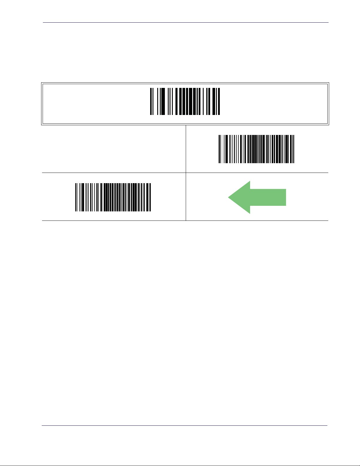
LED and Beeper Indicators
Power On Alert
Disables or enables the indication (from the Beeper) that the reader is receiving power.
LED and Beeper Indicators
ENTER/EXIT PROGRAMMING MODE
Power On Alert = Disable (No Audible Indication)
Power On Alert = Four Beeps
DEFAULT
Product Reference Guide 21
Page 30
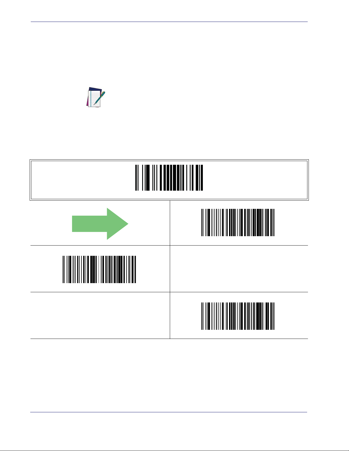
General Features
Good Read: When to Indicate
This feature specifies when the reader will provide indication (beep and/or flash its green
LED) upon successfully reading a barcode. Choices are:
• Good Read = Indicate after decode
• Good Read = Indicate after transmit
• Good Read = Indicate after CTS goes inactive, then active
This option, which uses CTS, is only valid for RS-232
interfaces.
NOTE
ENTER/EXIT PROGRAMMING MODE
DEFAULT
Indicate Good Read = After Transmit
Indicate Good Read = After Decode
Indicate Good Read = After CTS Goes Inactive, Then Active
22 QuickScan® QD2100
Page 31
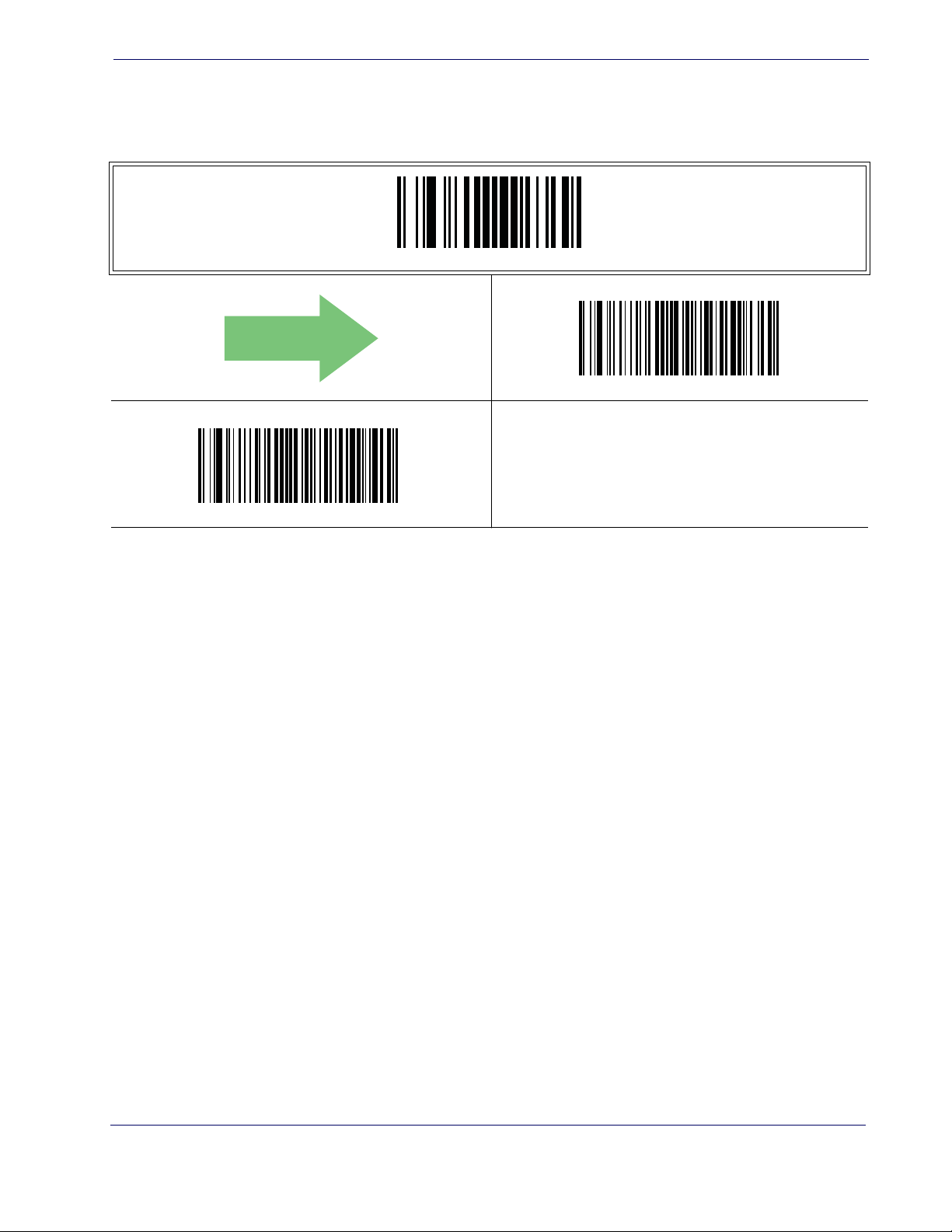
Good Read Beep Type
DEFAULT
Specifies whether the good read beep has a mono or bitonal beep sound.
LED and Beeper Indicators
ENTER/EXIT PROGRAMMING MODE
Good Read Beep Type = Mono
Good Read Beep Type = Bitonal
Product Reference Guide 23
Page 32

General Features
DEFAULT
Good Read Beep Frequency
Adjusts the good read beep to sound at a selectable low, medium or high frequency, selectable from the list below. (Controls the beeper’s pitch/tone.)
ENTER/EXIT PROGRAMMING MODE
Good Read Beep Frequency = Low
Good Read Beep Frequency = Medium
Good Read Beep Length
Specifies the duration of a good read beep.
Good Read Beep Frequency = High
ENTER/EXIT PROGRAMMING MODE
24 QuickScan® QD2100
Good Read Beep Length = 60 msec
Page 33

Good Read Beep Length — continued
ENTER/EXIT PROGRAMMING MODE
Good Read Beep Length = 80 msec
LED and Beeper Indicators
DEFAULT
Good Read Beep Length = 100 msec
Good Read Beep Length = 120 msec
Good Read Beep Length = 160 msec
Good Read Beep Length = 140 msec
Good Read Beep Length = 180 msec
Good Read Beep Length = 200 msec
Product Reference Guide 25
Page 34
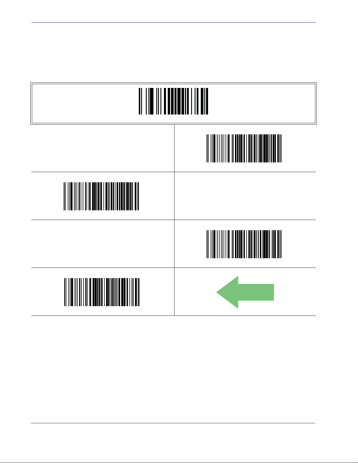
General Features
Good Read Beep Volume
Selects the beeper volume (loudness) upon a good read beep. There are three selectable
volume levels.
ENTER/EXIT PROGRAMMING MODE
Good Read Beep Volume = Beeper Off
Good Read Beep Volume = Low
Good Read Beep Volume = High
Good Read Beep Volume = Medium
DEFAULT
26 QuickScan® QD2100
Page 35

Good Read LED Duration
This feature specifies the amount of time that the Good Read LED remains on following
a good read. The good read LED on time can be set within a range of 10 milliseconds to
2,550 milliseconds (0.001 to 2.55 seconds) in 10ms increments.
Follow these instructions to set this feature:
1. Determine the desired setting in milliseconds. A setting of 0 means that the good read
LED stays on until the next time the trigger is pulled.
2. Divide the desired setting by 10 (setting is in 10ms increments). Pad the result with leading zeroes to yield three digits. For example: 0 = 000, 5 = 000, 20 = 020, etc.
3. Scan the ENTER/EXIT PROGRAMMING MODE barcode to enter Programming
Mode.
4. Scan the barcode: SELECT GOOD READ LED DURATION SETTING.
5. Scan the appropriate three digits from the keypad in Appendix E, Keypad representing the
duration which was determined in the steps above. You will hear a two-beep indication
after the last character.
LED and Beeper Indicators
If you make a mistake before the last character, scan the CANCEL barcode to
abort and not save the entry string. You can then start again at the beginning.
NOTE
6. Scan the ENTER/EXIT PROGRAMMING MODE barcode to exit Programming
Mode.
This completes the procedure. See Ta bl e 3 for some examples of how to set this feature.
Table 3. Good Read LED Duration Setting Examples
STEP ACTION EXAMPLES
Good Read LED
1 Desired Setting
Divide by 10 (and pad with leading
2
zeroes)
3 Scan ENTER/EXIT PROGRAMMING MODE
4 Scan SELECT LABEL GONE TIMEOUT SETTING
Scan Three Characters From
5
Appendix E, Keypad
6 Scan ENTER/EXIT PROGRAMMING MODE
stays on until next
trigger pull (00)
000 002 015 255
‘0’, ‘0’ and ‘0’ ‘0’, ‘0’ and ‘2’ ‘0’, ‘1’ and ‘5’ ‘2’, ‘5’ and ‘5’
20ms 150ms 2550ms (2.55 sec.)
Product Reference Guide 27
Page 36

General Features
Good Read LED Duration — cont.
ENTER/EXIT PROGRAMMING MODE
Select Good Read LED Duration Setting
Make a mistake? Scan the CANCEL barcode to abort and not
save the entry string. You can then start again at the beginning.
CANCEL
DEFAULT
Indicators are dimmed during sleep.
NOTE
020 = Good Read LED stays on for
2 seconds.
28 QuickScan® QD2100
Page 37

Scanning Features
Scan Mode
Selects the scan operating mode for the reader. Selections are:
Scanning Features
Trigger Single —
When the trigger is pulled, scanning is activated until one of the fol-
lowing occurs:
- Scanning Active Time has elapsed
- a label has been read
- the trigger is released
This mode is associated with typical handheld reader operation: when the trigger is
pulled, scanning starts and the product scans until the trigger is released, or a label is read,
or the maximum Scanning Active Time has elapsed.
Trigger Hold Multiple —
When the trigger is pulled, scanning starts and the product
scans until the trigger is released or Scanning Active Time has elapsed. Reading a label does
not disable scanning. Double Read Timeout prevents undesired multiple reads of the same
label while in this mode.
Trigger Pulse Multiple —
When the trigger is pulled, continuous scanning is activated
until Scanning Active Time has elapsed or the trigger has been released and pulled again.
Double Read Timeout1 prevents undesired multiple reads of the same label while in this
mode.
Flashing —
The reader flashes1 on and off regardless of the trigger status. Flash rate is
controlled by Flash On Time and Flash Off Time. When Flash is ON the imager reads continuously. When Flash is OFF scanning is deactivated.
Always On —
No trigger pull is required to read a barcode. Scanning is continually on.
If the trigger is pulled, the reader acts as if it is in Trigger Single Mode. Double Read
Timeout1 prevents undesired multiple reads of the same label while in this mode.
Stand Mode —
No trigger pull is required to read a barcode. Scanning is turned on automatically when an item is placed in reader’s field of view. If the trigger is pulled, the
reader acts as if it in single read mode. Double Read Timeout1 prevents undesired multiple
reads of the same label while in this mode.
Trigger Object Sense —
This mode is similar to Stand Mode, except that a trigger pull
is required to activate the decoder.
Product Reference Guide 29
1. Controlled by Flash On Time.
Page 38

General Features
Scan Mode — continued
ENTER/EXIT PROGRAMMING MODE
Scan Mode = Trigger Single
DEFAULT
Scan Mode = Trigger Hold Multiple
Scan Mode = Trigger Pulse Multiple
Scan Mode = Always On
Scan Mode = Flashing
Scan Mode = Stand Mode
Scan Mode = Trigger Object Sense
30 QuickScan® QD2100
Page 39
Stand Mode Triggered Timeout
This feature specifies the time to remain in Trigger Single mode after the trigger is pulled
while in Stand Mode.
Scanning Features
This timeout is only used when the Scan Mode is configured as
Mode.
NOTE
ENTER/EXIT PROGRAMMING MODE
Stand Mode Triggered Timeout = 0.5 Seconds
Stand
DEFAULT
Stand Mode Triggered Timeout = 1.5 Seconds
Stand Mode Triggered Timeout = 2 Seconds
Stand Mode Triggered Timeout = 3 Seconds
Stand Mode Triggered Timeout = 4 Seconds
Product Reference Guide 31
Page 40

General Features
Stand Mode Triggered Timeout — continued
ENTER/EXIT PROGRAMMING MODE
Stand Mode Triggered Timeout = 6 Seconds
Stand Mode Triggered Timeout = 8 Seconds
Stand Mode Triggered Timeout = Switch back to Trigger Single
on trigger pull
32 QuickScan® QD2100
Page 41

Scanning Active Time
This setting specifies the amount of time that the reader stays in scan ON state once the
state is entered. The range for this setting is from 1 to 255 seconds in 1-second increments.
Follow these instructions to set this feature:
1. Determine the desired setting.
2. Pad the result with leading zeroes to yield three digits. For example: 0 = 000, 5 = 005, 20
= 020, etc.
3. Scan the ENTER/EXIT PROGRAMMING MODE barcode to enter Programming
Mode.
4. Scan the barcode: SELECT SCANNING ACTIVE TIME SETTING.
5. Scan the appropriate three digits from the keypad in Appendix E, Keypad, that represent
the duration which was determined in the steps above. You will hear a two-beep indication after the last character.
Scanning Features
If you make a mistake before the last character, scan the CANCEL barcode to
abort and not save the entry string. You can then start again at the beginning.
NOTE
6. Scan the ENTER/EXIT PROGRAMMING MODE barcode to exit Programming
Mode.
This completes the procedure. See Ta bl e 4 for some examples of how to set this feature.
Table 4. Scanning Active Time Setting Examples
STEP ACTION EXAMPLES
1 Desired Setting 1 Second 90 Sec. (1.5 min.) 180 Sec. (3 min.) 255 Seconds (4.25 min.)
2 Pad leading zero(es) 001 090 180 255
3 Scan ENTER/EXIT PROGRAMMING MODE
4 Scan SELECT SCANNING ACTIVE TIME SETTING
Scan Three Characters From
5
Appendix E, Keypad
6 Scan ENTER/EXIT PROGRAMMING MODE
‘0’, ‘0’ and ‘1’ ‘0’, ‘9’ and ‘0’ ‘1’, ‘8’ and ‘0’ ‘2’, ‘5’ and ‘5’
Product Reference Guide 33
Page 42

General Features
Scanning Active Time — cont.
ENTER/EXIT PROGRAMMING MODE
Select Scanning Active Time Setting
Make a mistake? Scan the CANCEL barcode to abort and not
save the entry string. You can then start again at the beginning.
CANCEL
DEFAULT
005 = Scanning is active for 5 Seconds
34 QuickScan® QD2100
Page 43

Flash On Time
This feature specifies the ON time for the indicator LED while in Flash Mode. The selectable range is 100 to 9,900 milliseconds (0.1 to 9.9 seconds), in 100 millisecond increments.
Follow these instructions to set this feature.
Flash On Time
1. Determine the desired setting in milliseconds.
2. Divide the desired setting by 100 (setting is in 100ms increments). Pad the result with
leading zeroes to yield two digits. For example: 0 = 00, 5 = 05, 20 = 20, etc.
3. Scan the ENTER/EXIT PROGRAMMING MODE barcode to enter Programming
Mode.
4. Scan the barcode: SELECT FLASH ON TIME SETTING.
5. Scan the appropriate two digits from the keypad in Appendix E, Keypad representing the
duration which was determined in the steps above. You will hear a two-beep indication
after the last character.
If you make a mistake before the last character, scan the CANCEL barcode to
abort and not save the entry string. You can then start again at the beginning.
NOTE
6. Scan the ENTER/EXIT PROGRAMMING MODE barcode to exit Programming
Mode.
This completes the procedure. See Ta bl e 5 for some examples of how to set this feature.
Table 5. Flash On Time Setting Examples
STEP ACTION EXAMPLES
1 Desired Setting 500ms 1,000ms (1 sec.) 5200ms (5.2 sec.) 9,900ms (9.9 sec.)
Divide by 100 (and pad with
2
leading zeroes to yield two digits)
3 Scan ENTER/EXIT PROGRAMMING MODE
4 Scan SELECT FLASH OFF TIME SETTING
Scan Two Characters From
5
Appendix E, Keypad
6 Scan ENTER/EXIT PROGRAMMING MODE
05 10 52 99
‘0’ and ‘5’ ‘1’ and ‘0’ ‘5’ and ‘2’ ‘9’ and ‘9’
Product Reference Guide 35
Page 44

General Features
Flash On Time — cont.
ENTER/EXIT PROGRAMMING MODE
Select Flash ON Time Setting
Make a mistake? Scan the CANCEL barcode to abort and not
save the entry string. You can then start again at the beginning.
CANCEL
DEFAULT
10 = Flash is ON for 1 Second
36 QuickScan® QD2100
Page 45

Flash Off Time
This feature specifies the OFF time for the indicator LED while in Flash Mode. The selectable range is 100 to 9,900 milliseconds (0.1 to 9.9 seconds), in 100 millisecond increments.
Follow these instructions to set this feature.
Flash Off Time
1. Determine the desired setting in milliseconds.
2. Divide the desired setting by 100 (setting is in 100ms increments). Pad the result with
leading zeroes to yield two digits. For example: 0 = 00, 5 = 05, 20 = 20, etc.
3. Scan the ENTER/EXIT PROGRAMMING MODE barcode to enter Programming
Mode.
4. Scan the barcode: SELECT FLASH OFF TIME SETTING.
5. Scan the appropriate two digits from the keypad in Appendix E, Keypad, that represent the
duration which was determined in the steps above. You will hear a two-beep indication
after the last character.
If you make a mistake before the last character, scan the CANCEL barcode to
abort and not save the entry string. You can then start again at the beginning.
NOTE
6. Scan the ENTER/EXIT PROGRAMMING MODE barcode to exit Programming
Mode.
This completes the procedure. See Ta bl e 6 for some examples of how to set this feature.
Table 6. Flash Off Time Setting Examples
STEP ACTION EXAMPLES
1 Desired Setting 500ms 1,000ms (1 sec.) 5200ms (5.2 sec.) 9,900ms (9.9 sec.)
Divide by 100 (and pad with
2
leading zeroes to yield two digits)
3 Scan ENTER/EXIT PROGRAMMING MODE
4 Scan SELECT FLASH OFF TIME SETTING
Scan Two Characters From
5
Appendix E, Keypad
6 Scan ENTER/EXIT PROGRAMMING MODE
05 10 52 99
‘0’ and ‘5’ ‘1’ and ‘0’ ‘5’ and ‘2’ ‘9’ and ‘9’
Product Reference Guide 37
Page 46

General Features
Flash Off Time — cont.
ENTER/EXIT PROGRAMMING MODE
Select Flash OFF Time Setting
Make a mistake? Scan the CANCEL barcode to abort and not
save the entry string. You can then start again at the beginning.
CANCEL
DEFAULT
06 = Flash is OFF for 600ms
38 QuickScan® QD2100
Page 47

Stand Mode Sensitivity
Sets the sensitivity level for stand mode wakeup. Choices are low, medium and high.
Stand Mode Sensitivity
ENTER/EXIT PROGRAMMING MODE
Stand Mode Sensitivity = Low
DEFAULT
Stand Mode Sensitivity = Medium
Stand Mode Sensitivity = High
Product Reference Guide 39
Page 48
General Features
Green Spot Duration
Specifies the duration of the good read pointer beam after a good read.
ENTER/EXIT PROGRAMMING MODE
Green Spot Duration = Disable (Green Spot is Off)
DEFAULT
Green Spot Duration = Short (300 msec)
Green Spot Duration = Long (800 msec)
Green Spot Duration = Medium (500 msec)
40 QuickScan® QD2100
Page 49

RS-232 ONLY Interface
Introduction
Use the programming barcodes in this chapter if modifications to the standard RS-232
interface settings are necessary to meet your system’s requirements. Additional settings
which apply to both the RS-232 and USB interfaces are available in
USB-Com Interfaces
RS-232 Standard Factory Settings
Reference Appendix B, Standard Defaults for a listing of standard factory settings.
Baud Rate
Baud rate is the number of bits of data transmitted per second. Set the reader's baud rate
to match the baud rate setting of the host device. With an improper baud rate setting,
data may not reach the host correctly.
.
Chapter 5
Chapter 6, RS-232/
ENTER/EXIT PROGRAMMING MODE
Baud Rate = 1200
Baud Rate = 2400
Baud Rate = 4800
Product Reference Guide 41
Page 50
RS-232 ONLY Interface
DEFAULT
Baud Rate — continued
ENTER/EXIT PROGRAMMING MODE
Baud Rate = 9600
Baud Rate = 19,200
Baud Rate = 38,400
Baud Rate = 115,200
Baud Rate = 57,600
42 QuickScan® QD2100
Page 51

Data Bits
Data Bits
This parameter allows the reader to interface with devices requiring a 7-bit or 8-bit
ASCII protocol for sending and receiving data.
ENTER/EXIT PROGRAMMING MODE
7 Data Bits
DEFAULT
8 Data Bits
Product Reference Guide 43
Page 52

RS-232 ONLY Interface
Stop Bits
The stop bit(s) at the end of each transmitted character marks the end of transmission of
one character and prepares the receiving device for the next character in the serial data
stream. The number of stop bits selected (one or two) depends on the number the receiving terminal is programmed to accommodate. Set the number of stop bits to match host
device requirements.
ENTER/EXIT PROGRAMMING MODE
DEFAULT
1 Stop Bit
2 Stop Bits
44 QuickScan® QD2100
Page 53

Parity
Parity
This feature specifies parity required for sending and receiving data. A parity check bit is
the most significant bit of each ASCII coded character. Select the parity type according
to host device requirements.
• Select None when no parity bit is required.
• Select Odd parity and the parity bit value is set to 0 or 1, based on data, to ensure that an
odd number of 1 bits are contained in the coded character.
• Select Even parity and the parity bit value is set to 0 or 1, based on data, to ensure that an
even number of 1 bits are contained in the coded character.
ENTER/EXIT PROGRAMMING MODE
DEFAULT
Parity = Even
Parity = None
Parity = Odd
Product Reference Guide 45
Page 54

RS-232 ONLY Interface
Handshaking Control
The data interface consists of an RS-232 port designed to operate either with or without
the hardware handshaking lines, Request to Send (RTS), and Clear to Send (CTS). Hand-
shaking Control includes the following options:
• RTS — RTS is asserted during transmissions. CTS is ignored.
• RTS/CTS — RTS is asserted during transmissions. CTS gates transmissions.
• RTS/XON/XOFF — RTS is asserted during transmissions. CTS is ignored. XON and
XOFF gate transmissions.
• RTS On/CTS — RTS is always asserted. CTS gates transmissions.
• RTS/CTS Scan Control — RTS is asserted during transmissions. CTS gates transmissions and controls enable and disable state of scanner.
ENTER/EXIT PROGRAMMING MODE
DEFAULT
Handshaking Control = RTS/CTS
Handshaking Control = RTS On/CTS
Handshaking Control = RTS
Handshaking Control = RTS/XON/XOFF
Handshaking Control = RTS/CTS Scan Control
46 QuickScan® QD2100
Page 55

RS-232/USB-Com Interfaces
Introduction
The programming barcodes in this chapter allow modifications to the standard RS-232
and USB-Com interfaces.
Standard Factory Settings
Reference Appendix B, Standard Defaults for a listing of standard factory settings.
Chapter 6
Product Reference Guide 47
Page 56

RS-232/USB-Com Interfaces
Intercharacter Delay
This parameter specifies the intercharacter delay between the end of one character and the
beginning of the next. The delay can be set within a range of zero (0) to 990 milliseconds
in 10ms increments. A setting of zero specifies no delay.
To set the delay:
1. Determine the desired setting in milliseconds.
2. Divide the desired setting by 10 (setting is in 10ms increments). Pad the result with leading zeroes to yield two digits. For example: 0 = 00, 5 = 05, 20 = 20, etc.
3. Scan the ENTER/EXIT PROGRAMMING MODE barcode to enter Programming
Mode.
4. Scan the barcode: SELECT INTERCHARACTER DELAY SETTING.
5. Scan the appropriate two digits from the keypad in Appendix E, Keypad, that represent
the duration which was determined in the steps above. You will hear a two-beep indication after the last character.
If you make a mistake before the last character, scan the CANCEL barcode to
abort and not save the entry string. You can then start again at the beginning.
NOTE
6. Scan the ENTER/EXIT PROGRAMMING MODE barcode to exit Programming
Mode.
This completes the procedure. See Table 7 for some examples of how to set this feature.
Table 7. Intercharacter Delay Setting Examples
STEP ACTION EXAMPLES
1 Desired Setting 50ms 150ms 600ms 850ms
Divide by 10 (and pad with leading
2
zeroes to yield two-digits)
3 Scan ENTER/EXIT PROGRAMMING MODE
4 Scan SELECT INTERCHARACTER DELAY SETTING
Scan Two Characters From
5
Appendix E, Keypad
6 Scan ENTER/EXIT PROGRAMMING MODE
05 15 60 85
‘0’ and ‘5’ ‘5’ and ‘0’ 0’ and ‘0’ ‘8’ and ‘5’
48 QuickScan® QD2100
Page 57

Intercharacter Delay — cont.
ENTER/EXIT PROGRAMMING MODE
Select Intercharacter Delay Setting
Intercharacter Delay
Intercharacter Delay = No Delay
Make a mistake? Scan the CANCEL barcode to abort and not
save the entry string. You can then start again at the beginning.
DEFAULT
00 = No Intercharacter Delay
CANCEL
Product Reference Guide 49
Page 58
RS-232/USB-Com Interfaces
Beep On ASCII BEL
When this parameter is enabled, the reader issues a beep when a <BEL> character is detected on the RS-232 serial line. <BEL> is issued to gain a user's attention to an illegal
entry or other important event.
Beep On ASCII BEL = Disable
ENTER/EXIT PROGRAMMING MODE
DEFAULT
Beep On Not on File
This option enables/disables the action of the reader to sound a three beep sequence upon
receiving a Not-On-File (NOF) host command.
Beep On Not On File = Disable
DEFAULT
Beep On ASCII BEL = Enable
ENTER/EXIT PROGRAMMING MODE
Beep On Not On File = Enable
50 QuickScan® QD2100
Page 59
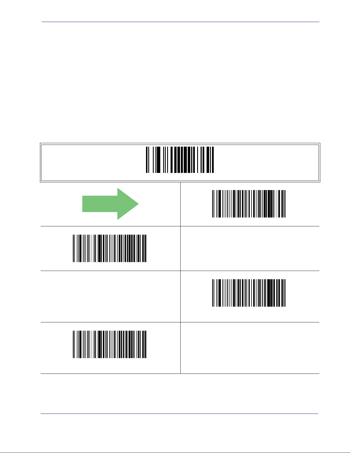
ACK NAK Options
This enables/disables the ability of the reader to support the RS-232 ACK/NAK protocol. When configured, the reader and/or host sends an “ACK” when it receives data
properly, and sends “NAK” when the data is in error.
Options are:
•Disable
• Enable for label transmission — The reader expects an ACK/NAK response from the host
when a label is sent.
• Enable for host-command acknowledge — The reader will respond with ACK/NAK
when the host sends a command.
• Enable for label transmission and host-command acknowledge
ACK NAK Options
ENTER/EXIT PROGRAMMING MODE
DEFAULT
ACK/NAK Protocol = Enable for label transmission
ACK/NAK Protocol = Enable for label transmission and host-com-
mand acknowledge
ACK/NAK Protocol = Disable ACK/NAK
ACK/NAK Protocol = Enable for host-command
acknowledge
Product Reference Guide 51
Page 60

RS-232/USB-Com Interfaces
ACK Character
This setting specifies an ASCII character or hex value to be used as the ACK character.
ASCII characters or any hex value from 0 to 0xFF can be selected.
To set this feature:
1. Determine the desired character or value.
2. Use the ASCII Chart on the inside back cover of this manual to find the hex equivalent
3. Scan the ENTER/EXIT PROGRAMMING MODE barcode to enter Programming
4. Scan the barcode: SELECT ACK CHARACTER SETTING.
5. Scan the appropriate two alpha-numeric characters from the keypad in Appendix E,
Setting to previously defined characters such as XON, XOFF, or host
commands conflicts with normal operation of these characters. 8-bit
NOTE
data is not recognized when the option
Data Bits.
Data Bits has been set as 7
for the desired character/value.
Mode.
Keypad, that represent the desired character/value in step 1 above. The second character
will cause a two-beep indication.
6. Scan the ENTER/EXIT PROGRAMMING MODE barcode to exit Programming
Mode.
This completes the procedure. See Table 8 for some examples of how to set this feature.
Table 8. ACK Character Setting Examples
STEP ACTION EXAMPLES
1 Desired Character/Value ACK $ @ >
2 Hex equivalent 0x06 0x24 0x40 0x3E
3 Scan ENTER/EXIT PROGRAMMING MODE
4 Scan SELECT ACK CHARACTER SETTING
Scan Two Characters From
5
Appendix E, Keypad
6 Scan ENTER/EXIT PROGRAMMING MODE
‘0’ and ‘6’ ‘2’ and ‘4’ ‘4’ and ‘0’ ‘3’ AND ‘E’
52 QuickScan® QD2100
Page 61

ACK Character — cont.
Select ACK Character Setting
ACK NAK Options
ENTER/EXIT PROGRAMMING MODE
DEFAULT
0x06 ‘ACK’ Character
Product Reference Guide 53
Page 62

RS-232/USB-Com Interfaces
NAK Character
This setting specifies an ASCII character or hex value to be used as the NAK character.
ASCII characters or any hex value from 0 to 0xFF can be selected.
To set this feature:
1. Determine the desired character or value.
2. Use the ASCII Chart on the inside back cover of this manual to find the hex equivalent
3. Scan the ENTER/EXIT PROGRAMMING MODE barcode to enter Programming
4. Scan the barcode: SELECT NAK CHARACTER SETTING.
5. Scan the appropriate two alpha-numeric characters from the keypad in Appendix E,
Setting to previously defined characters such as XON, XOFF, or host
commands conflicts with normal operation of these characters. 8-bit
NOTE
data is not recognized when the option
Data Bits.
Data Bits has been set as 7
for the desired character/value.
Mode.
Keypad, that represent the desired character/value in step 1 above. The second character
will cause a two-beep indication.
6. Scan the ENTER/EXIT PROGRAMMING MODE barcode to exit Programming
Mode.
This completes the procedure. See Table 9 for some examples of how to set this feature.
Table 9. NAK Character Setting Examples
STEP ACTION EXAMPLES
1 Desired Character/Value NAK $ @ >
2 Hex equivalent 0x15 0x24 0x40 0x3E
3 Scan ENTER/EXIT PROGRAMMING MODE
4 Scan SELECT ACK CHARACTER SETTING
Scan Two Characters From
5
Appendix E, Keypad
6 Scan ENTER/EXIT PROGRAMMING MODE
‘1’ and ‘5’ ‘2’ and ‘4’ ‘4’ and ‘0’ ‘3’ AND ‘E’
54 QuickScan® QD2100
Page 63
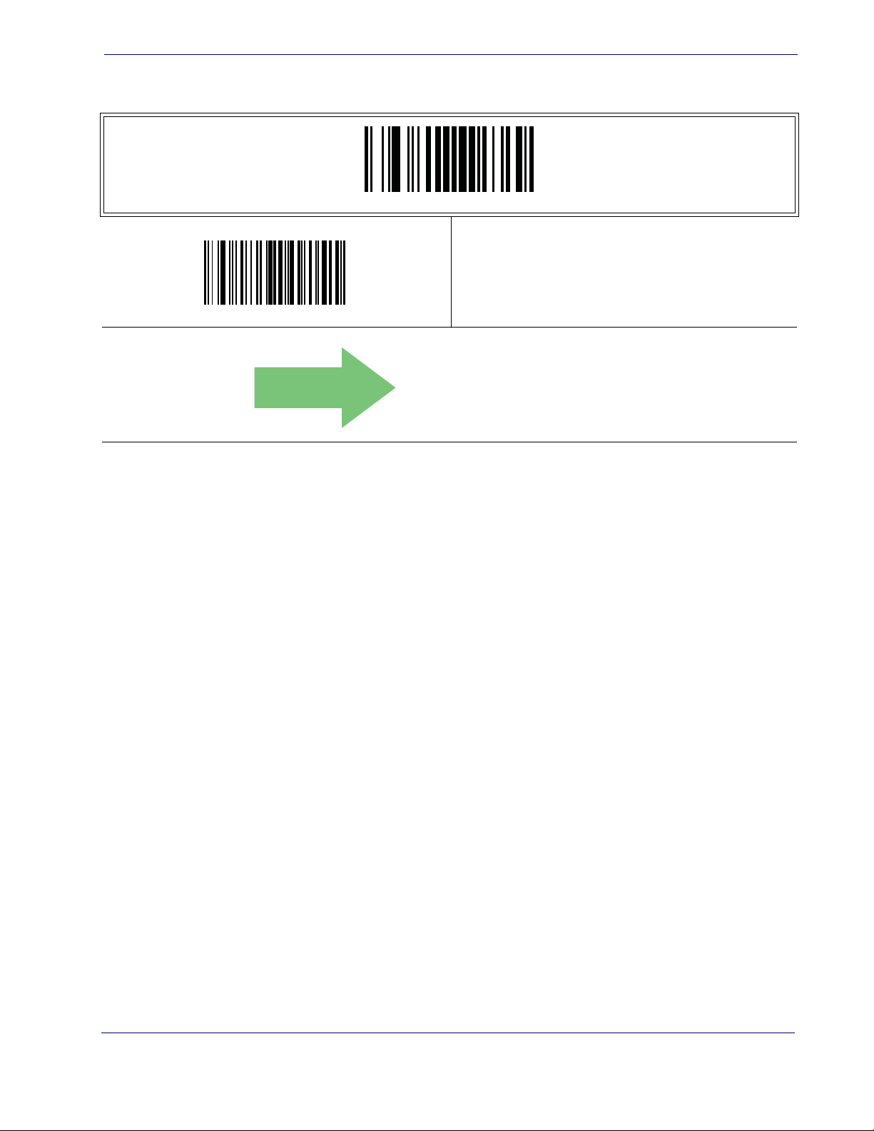
NAK Character — cont.
Select NAK Character Setting
ACK NAK Options
ENTER/EXIT PROGRAMMING MODE
DEFAULT
0x15 ‘NAK’ Character
Product Reference Guide 55
Page 64

RS-232/USB-Com Interfaces
ACK NAK Timeout Value
This option specifies the amount of time the reader waits for an ACK character from the
host following label transmission. The selectable timeout range is 200 milliseconds to
15,000ms (15 seconds) in 200ms increments. A selection of 0 disables the timeout.
To set this value:
1. Determine the desired setting in milliseconds.
2. Divide the desired setting by 200 (setting is in 200ms increments). Pad the result with
leading zeroes to yield two digits. For example: 0 = 00, 5 = 05, 20 = 20, etc.
3. Scan the ENTER/EXIT PROGRAMMING MODE barcode to enter Programming
Mode.
4. Scan the barcode: SELECT ACK NAK TIMEOUT VALUE SETTING.
5. Scan the appropriate two digits from the keypad in Appendix E, Keypad, that represent
the duration which was determined in the steps above. You will hear a two-beep indication after the last character.
If you make a mistake before the last character, scan the CANCEL barcode to
abort and not save the entry string. You can then start again at the beginning.
NOTE
6. Scan the ENTER/EXIT PROGRAMMING MODE barcode to exit Programming
Mode.
This completes the procedure. See Table 10 for some examples of how to set this feature.
Table 10. ACK NAK Timeout Value Setting Examples
STEP ACTION EXAMPLES
1 Desired Setting 200ms 1,000ms (1 sec.) 5200ms (5.2 sec.) 15,000ms (1 sec.)
2 Divide by 200 01 05 26 75
3 Scan ENTER/EXIT PROGRAMMING MODE
4 Scan SELECT ACK NAK TIMEOUT VALUE SETTING
Scan Two Characters From
5
Appendix E, Keypad
7 Scan ENTER/EXIT PROGRAMMING MODE
‘0’ and ‘1’ ‘0’ and ‘5’ ‘2’ and ‘6’ ‘7’ and ‘5’
56 QuickScan® QD2100
Page 65

ACK NAK Timeout Value — cont.
DEFAULT
ENTER/EXIT PROGRAMMING MODE
Select ACK NAK Timeout Value Setting
Make a mistake? Scan the CANCEL barcode to abort and not
save the entry string. You can then start again at the beginning.
ACK NAK Options
CANCEL
01 ACK NAK Timeout value is 200ms
Product Reference Guide 57
Page 66

RS-232/USB-Com Interfaces
ACK NAK Retry Count
This feature specifies the number of times the reader retries a label transmission due to a
retry condition. The selectable range is from 1 to 254 retries. A selection of 0 disables the
count, and a selection of 255 specifies unlimited retries.
To set this feature:
1. Determine the desired setting.
2. Pad the number with leading zeroes to yield three digits. For example: 0 = 000, 5 = 005,
20 = 020, etc.
3. Scan the ENTER/EXIT PROGRAMMING MODE barcode to enter Programming
Mode.
4. Scan the barcode: SELECT ACK NAK RETRY COUNT SETTING.
5. Scan the appropriate three digits from the keypad in Appendix E, Keypad, that repre-
sent the number which was determined in the steps above. You will hear a two-beep indication after the last character.
If you make a mistake before the last character, scan the CANCEL barcode to
abort and not save the entry string. You can then start again at the beginning.
NOTE
6. Scan the ENTER/EXIT PROGRAMMING MODE barcode to exit Programming
Mode.
This completes the procedure. See Table 11 for some examples of how to set this feature.
Table 11. ACK NAK Retry Count Setting Examples
STEP ACTION EXAMPLES
1 Desired Setting
2 Pad with leading zero(es) 000 003 054 255
3 Scan ENTER/EXIT PROGRAMMING MODE
4 Scan SELECT ACK NAK RETRY COUNT SETTING
Scan Three Characters From
5
Appendix E, Keypad
6 Scan ENTER/EXIT PROGRAMMING MODE
Disable Retry
Count
‘0’, ‘0’ and ‘0’ ‘0’, ‘0’ and ‘3’ ‘0’, ‘5’ and ‘4’ ‘2’, ‘5’ and ‘5’
3 Retries 54 Retries Unlimited Retries
58 QuickScan® QD2100
Page 67
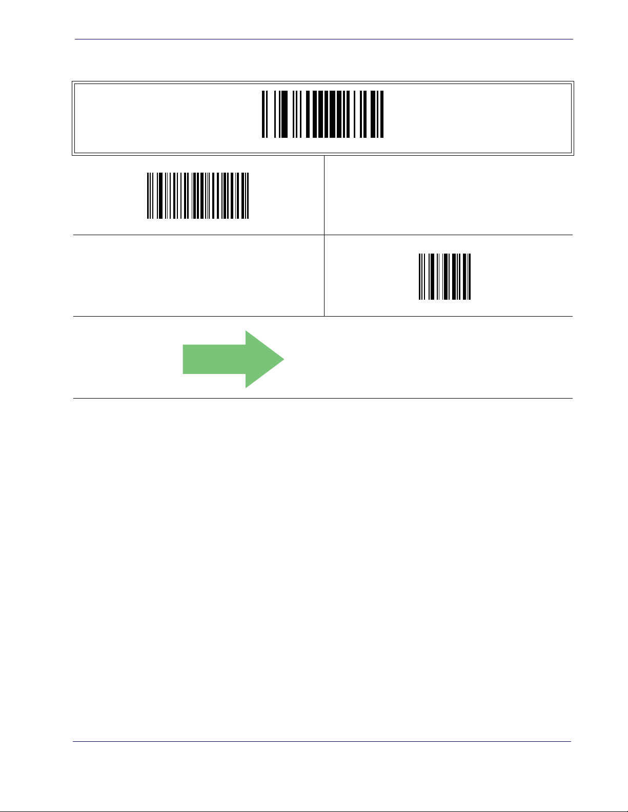
ACK NAK Retry Count — cont.
ENTER/EXIT PROGRAMMING MODE
Select ACK NAK Retry Count Setting
Make a mistake? Scan the CANCEL barcode to abort and not
save the entry string. You can then start again at the beginning.
ACK NAK Options
CANCEL
DEFAULT
003 = 3 Retries
Product Reference Guide 59
Page 68

RS-232/USB-Com Interfaces
ACK NAK Error Handling
This feature specifies the method the reader uses to handle receive errors detected while
waiting for an ACK character from the host.
Options are:
• Ignore errors detected
• Process error as valid ACK character
• Process error as valid NAK character
DEFAULT
ENTER/EXIT PROGRAMMING MODE
ACK NAK Error Handling = Process Error as Valid ACK Character
ACK NAK Error Handling = Ignore Errors Detected
ACK NAK Error Handling = Process Error as
Valid NAK Character
60 QuickScan® QD2100
Page 69

Indicate Transmission Failure
This option enables/disables the reader’s ability to sound an error beep to indicate a
transmission failure while in ACK/NAK mode.
ENTER/EXIT PROGRAMMING MODE
Indicate Transmission Failure
Indicate Transmission Failure = Disable Indication
DEFAULT
Indicate Transmission Failure = Enable Indication
Product Reference Guide 61
Page 70

RS-232/USB-Com Interfaces
Disable Character
Specifies the value of the RS-232 host command used to disable the reader.
ASCII characters or any hex value from 0 to 0xFF can be selected.
To set the value:
1. Determine the desired character or value. A setting of 0xFF indicates the the Disable
Character is not used (not available).
2. Use the ASCII Chart on the inside back cover of this manual to find the hex equivalent
for the desired character/value.
3. Scan the ENTER/EXIT PROGRAMMING MODE barcode to enter Programming
Mode.
4. Scan the barcode: SELECT DISABLE CHARACTER SETTING.
5. Scan the appropriate two alpha-numeric characters from the keypad in Appendix E,
Keypad, that represent the desired character/value in step 1 above. The second character
will cause a two-beep indication.
NOTE
Setting to previously defined characters such as XON, XOFF, or host
commands conflicts with normal operation of these characters. 8-bit
data is not recognized when the option
Data Bits.
Data Bits has been set as 7
6. Scan the ENTER/EXIT PROGRAMMING MODE barcode to exit Programming
Mode.
This completes the procedure. See Table 12 for some examples of how to set this feature.
Table 12. Disable Character Setting Examples
STEP ACTION EXAMPLES
1 Desired character/value ‘d’ ‘}’ ‘D’
2 Hex equivalent 0x64 0x7D 0x44 0xFF
3 Scan ENTER/EXIT PROGRAMMING MODE
4 Scan SELECT DISABLE CHARACTER VALUE SETTING
Scan Two Characters From
5
Appendix E, Keypad
6 Scan ENTER/EXIT PROGRAMMING MODE
‘6’ and ‘4’ ‘7’ and ‘D’ ‘4’ and ‘4’ ‘F’ AND ‘F’
Disable Command
Not Used
62 QuickScan® QD2100
Page 71

Disable Character — cont.
ENTER/EXIT PROGRAMMING MODE
Select Disable Character Setting
Disable Character
DEFAULT
0x44 = Disable Character is ‘D’
Product Reference Guide 63
Page 72

RS-232/USB-Com Interfaces
Enable Character
Specifies the value of the RS-232 host command used to enable the reader.
ASCII characters or any hex value from 0 to 0xFF can be selected.
To set this feature:
Determine the desired character or value. A setting of 0xFF indicates the the Enable
Character is not used (not available).
1. Determine the desired character or value.
2. Use the ASCII Chart on the inside back cover of this manual to find the hex equivalent
3. Scan the ENTER/EXIT PROGRAMMING MODE barcode to enter Programming
4. Scan the barcode: SELECT ENABLE CHARACTER SETTING.
Setting to previously defined characters such as XON, XOFF, or host
commands conflicts with normal operation of these characters. 8-bit
data is not recognized when the option
NOTE
Data Bits.
for the desired character/value.
Mode.
Data Bits has been set as 7
5. Scan the appropriate two alpha-numeric characters from the keypad in Appendix E,
Keypad, that represent the desired character/value in step 2 above. The second character
will cause a two-beep indication.
6. Scan the ENTER/EXIT PROGRAMMING MODE barcode to exit Programming
Mode.
This completes the procedure. See Table 13 for some examples of how to set this feature.
Table 13. Enable Character Setting Examples
STEP ACTION EXAMPLES
1 Desired character/value ‘e’ ‘}’ ‘E’
2 Hex equivalent 0x65 0x7D 0x45 0xFF
3 Scan ENTER/EXIT PROGRAMMING MODE
4 Scan SELECT DISABLE CHARACTER VALUE SETTING
Scan Two Characters From
5
Appendix E, Keypad
6 Scan ENTER/EXIT PROGRAMMING MODE
‘6’ and ‘5’ ‘7’ and ‘D’ ‘4’ and ‘5’ ‘F’ AND ‘F’
Enable Command
Not Used
64 QuickScan® QD2100
Page 73

Enable Character — cont.
ENTER/EXIT PROGRAMMING MODE
Select Enable Character Setting
Enable Character
DEFAULT
0x45 = Enable Character is ‘E’
Product Reference Guide 65
Page 74

RS-232/USB-Com Interfaces
NOTES
66 QuickScan® QD2100
Page 75

Introduction
Use the programming barcodes in this chapter to select options for USB Keyboard and
Wedge Interfaces.
Standard Factory Settings
Reference Appendix B, Standard Defaults for a listing of standard factory settings.
Scancode Tables
Information about control character emulation which applies to keyboard interfaces is
listed in Appendix F, Scancode Tables.
Chapter 7
Keyboard Interface
Product Reference Guide 67
Page 76

Keyboard Interface
Country Mode
This feature specifies the country/language supported by the keyboard.
Only the following interfaces support ALL Country Modes.
• USB Keyboard (without alternate key encoding)
• AT, PS/2 25-286, 30-286, 50, 50Z, 60, 70, 80, 90 & 95 w/Std Key Encoding
• Keyboard Wedge for IBM AT PS2 with standard key encoding but without external key-
• AT, PS/2 25-286, 30-286, 50, 50Z, 60, 70, 80, 90 & 95 without Alternate Key
• Keyboard Wedge for IBM AT PS2 without alternate key encoding but without external
All other interfaces support ONLY the following Country Modes: U.S., Belgium, Britain, France, Germany, Italy, Spain, Sweden.
board
keyboard
ENTER/EXIT PROGRAMMING MODE
DEFAULT
Country Mode = Belgium
Country Mode = Croatia
Country Mode = U.S.
Country Mode = Britain
Supports only the interfaces listed in theCountry Mode feature
description.
Supports only the interfaces listed in theCountry Mode feature
description.
Country Mode = Czechoslovakia
68 QuickScan® QD2100
Page 77
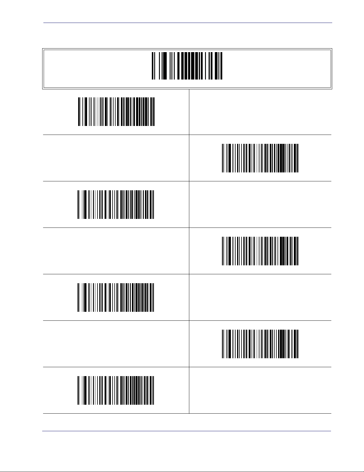
Country Mode — continued
ENTER/EXIT PROGRAMMING MODE
Country Mode = Denmark
Country Mode
Supports only the interfaces listed in theCountry Mode feature
description.
Country Mode = France
Country Mode = Germany
Supports only the interfaces listed in theCountry Mode feature
description.
Country Mode = Italy
Supports only the interfaces listed in theCountry Mode feature
description.
Country Mode = Hungary
Country Mode = Japanese 106-key
Supports only the interfaces listed in theCountry Mode feature
description.
Country Mode = Norway
Product Reference Guide 69
Page 78
Keyboard Interface
Country Mode — continued
ENTER/EXIT PROGRAMMING MODE
Country Mode = Poland
Supports only the interfaces listed in theCountry Mode feature
description.
Supports only the interfaces listed in theCountry Mode feature
description.
Country Mode = Portugal
Country Mode = Romania
Supports only the interfaces listed in theCountry Mode feature
description.
Country Mode = Spain
Supports only the interfaces listed in theCountry Mode feature
description.
Country Mode = Slovakia
Country Mode = Sweden
Supports only the interfaces listed in theCountry Mode feature
description.
Country Mode = Switzerland
70 QuickScan® QD2100
Page 79
Caps Lock State
This option specifies the format in which the reader sends character data. This applies to
keyboard wedge interfaces. This does not apply when an alternate key encoding keyboard
is selected.
DEFAULT
Caps Lock State
ENTER/EXIT PROGRAMMING MODE
Caps Lock State = Caps Lock OFF
Numlock
Caps Lock State = Caps Lock ON
Caps Lock State = AUTO Caps Lock Enable
This option specifies the setting of the Numbers Lock (Numlock) key while in keyboard
wedge interface. This only applies to alternate key encoding interfaces. It does not apply
to USB keyboard.
ENTER/EXIT PROGRAMMING MODE
DEFAULT
Numlock = Numlock key unchanged
Numlock = Numlock key toggled
Product Reference Guide 71
Page 80

Keyboard Interface
Send Control Characters
This feature Specifies how the reader transmits ASCII control characters to the host. Reference
Options are as follows:
Appendix F, Scancode Tables for more information about control characters.
Control Character 00 —
Characters from 00 to 0x1F are sent as control character
Ctrl+Keys, special keys are located from 0x80 to 0xA1.
Control Character 01 —
Characters from 00 to 0x1F are sent as control character
Ctrl+Capital Key, special keys are located from 0x80 to 0xA1.
Control Character 02 —
Special keys are located from 00 to 0x1F and characters from
0x80 to 0xFE are intended as an extended ASCII table (Microsoft Windows Codepage
1252 — see Microsoft Windows Codepage 1252 on page 306).
ENTER/EXIT PROGRAMMING MODE
DEFAULT
Wedge Send Control Characters = 00
Wedge Send Control Characters = 01
Wedge Send Control Characters = 02
72 QuickScan® QD2100
Page 81

Wedge Quiet Interval
This option specifies the amount of time to look for keyboard activity before the reader breaks the keyboard connection in order to transmit data to host. The selectable
range for this feature is from 0 to 990ms in 10ms increments.
NOTE
Follow these instructions to set this feature:
1. Determine the desired setting in milliseconds.
2. Divide the desired setting by 10 (setting is in 10ms increments). Pad the result with leading zeroes to yield two digits. For example: 0 = 00, 5 = 05, 20 = 20, etc.
3. Scan the ENTER/EXIT PROGRAMMING MODE barcode to enter Programming
Mode.
4. Scan the barcode: SELECT WEDGE QUIET INTERVAL SETTING.
5. Scan the appropriate two digits from the keypad in Appendix E, Keypad, that represent
the duration which was determined in the steps above. You will hear a two-beep indication after the last character.
Wedge Quiet Interval
This feature applies ONLY to the Keyboard Wedge interface.
If you make a mistake before the last character, scan the CANCEL barcode to
abort and not save the entry string. You can then start again at the beginning.
NOTE
6. Scan the ENTER/EXIT PROGRAMMING MODE barcode to exit Programming
Mode.
This completes the procedure to set the Wedge Quiet Interval. See Table 14 for some
examples of how to set this feature.
Table 14. Timeout Setting Examples
STEP ACTION EXAMPLES
1 Desired Setting 10ms 150ms 600ms 850ms
Divide by 10 (and pad with leading
2
zeroes)
3 Scan ENTER/EXIT PROGRAMMING MODE
4 Scan SELECT WEDGE QUIET INTERVAL SETTING
Scan Two Characters From
5
Appendix E, Keypad
01 15 60 85
‘0’ and ‘1’ ‘1’ and ‘5’ ‘6’ and ‘0’ ‘8’ and ‘5’
6 Scan ENTER/EXIT PROGRAMMING MODE
Product Reference Guide 73
Page 82

Keyboard Interface
Wedge Quiet Interval — cont.
ENTER/EXIT PROGRAMMING MODE
Select Wedge Quiet Interval Setting
Make a mistake? Scan the CANCEL barcode to abort and not
save the entry string. You can then start again at the beginning.
CANCEL
DEFAULT
10 = Quiet Interval of 100 ms
74 QuickScan® QD2100
Page 83

Intercharacter Delay
This parameter specifies the intercharacter delay between the end of one character
and the beginning of the next. The delay can be set within a range of zero (0) to 990
milliseconds in 10ms increments. A setting of zero specifies no delay.
NOTE
To set the delay:
1. Determine the desired setting in milliseconds.
2. Divide the desired setting by 10 (setting is in 10ms increments). Pad the result with leading zeroes to yield two digits. For example: 0 = 00, 5 = 05, 20 = 20, etc.
3. Scan the ENTER/EXIT PROGRAMMING MODE barcode to enter Programming
Mode.
4. Scan the barcode: SELECT INTERCHARACTER DELAY SETTING.
5. Scan the appropriate two digits from the keypad in Appendix E, Keypad, that represent
the duration which was determined in the steps above. You will hear a two-beep indication after the last character.
Intercharacter Delay
This feature applies ONLY to the Keyboard Wedge interface.
If you make a mistake before the last character, scan the CANCEL barcode to
abort and not save the entry string. You can then start again at the beginning.
NOTE
6. Scan the ENTER/EXIT PROGRAMMING MODE barcode to exit Programming
Mode.
This completes the procedure. See Ta bl e 1 4 for some examples of how to set this
feature.
Table 15. Intercharacter Delay Setting Examples
STEP ACTION EXAMPLES
1 Desired Setting 50ms 150ms 600ms 850ms
Divide by 10 (and pad with leading
2
zeroes to yield two-digits)
3 Scan ENTER/EXIT PROGRAMMING MODE
4 Scan SELECT INTERCHARACTER DELAY SETTING
Scan Two Characters From
5
Appendix E, Keypad
05 15 60 85
‘0’ and ‘5’ ‘1’ and ‘5’ ‘6’ and ‘0’ ‘8’ and ‘5’
6 Scan ENTER/EXIT PROGRAMMING MODE
Product Reference Guide 75
Page 84

Keyboard Interface
Intercharacter Delay — cont.
ENTER/EXIT PROGRAMMING MODE
Select Intercharacter Delay Setting
Intercharacter Delay = No Delay
Make a mistake? Scan the CANCEL barcode to abort and not
save the entry string. You can then start again at the beginning.
DEFAULT
00 = No Intercharacter Delay
CANCEL
76 QuickScan® QD2100
Page 85

Intercode Delay
Specifies the delay between labels transmitted to the host for this interface. The selectable
range for this feature is from 0 to 99 seconds.
Follow these instructions to set this feature:
1. Determine the desired setting.
2. Pad the number with leading zeroes to yield two digits. For example: 0 = 00, 5 = 05, 20 =
3. Scan the ENTER/EXIT PROGRAMMING MODE barcode to enter Programming
4. Scan the barcode: SELECT INTERCODE DELAY SETTING.
5. Scan the appropriate two digits from the keypad in Appendix E, Keypad, that represent
Intercode Delay
20, etc
Mode.
the duration which was determined in the steps above. You will hear a two-beep indication after the last character.
If you make a mistake before the last character, scan the CANCEL barcode to
abort and not save the entry string. You can then start again at the beginning.
NOTE
6. Scan the ENTER/EXIT PROGRAMMING MODE barcode to exit Programming
Mode.
This completes the procedure. See Table 16 for some examples of how to set this feature.
Table 16. Wedge Intercode Delay Examples
STEP ACTION EXAMPLES
1 Desired Setting No Delay 5 Seconds 60 Seconds 99 Seconds
2 Pad with leading zero(es) 00 05 60 99
3 Scan ENTER/EXIT PROGRAMMING MODE
4 Scan SELECT INTERCODE DELAY SETTING
Scan Two Characters From
5
Appendix E, Keypad
7 Scan ENTER/EXIT PROGRAMMING MODE
‘0’ and ‘0’ ‘0’ and ‘5’ ‘6’ and ‘0’ ‘9’ AND ‘9’
Product Reference Guide 77
Page 86

Keyboard Interface
DEFAULT
Intercode Delay — cont.
ENTER/EXIT PROGRAMMING MODE
Set Intercode Delay
Make a mistake? Scan the CANCEL barcode to abort and not
save the entry string. You can then start again at the beginning.
CANCEL
00 = No Wedge Intercode Delay
78 QuickScan® QD2100
Page 87

USB Keyboard Speed
This option specifies the USB poll rate for a USB keyboard.
NOTE
DEFAULT
USB Keyboard Speed
This feature applies ONLY to the USB Keyboard interface.
ENTER/EXIT PROGRAMMING MODE
USB Keyboard Speed = 1ms
USB Keyboard Speed = 2ms
USB Keyboard Speed = 4ms
USB Keyboard Speed = 3ms
USB Keyboard Speed = 5ms
Product Reference Guide 79
Page 88

Keyboard Interface
USB Keyboard Speed — continued
ENTER/EXIT PROGRAMMING MODE
USB Keyboard Speed = 6ms
USB Keyboard Speed = 7ms
USB Keyboard Speed = 8ms
USB Keyboard Speed = 10ms
USB Keyboard Speed = 9ms
80 QuickScan® QD2100
Page 89

Introduction
Feature settings for USB interfaces differ depending upon which host type the reader will
be connected with. Use the feature settings in this chapter and Chapter 9, IBM 46XX
Interface
included in the approprite chapter for their host type.
to specifically configure for the USB-OEM interface. Other USB interfaces are
Standard Factory Settings
Reference Appendix B, Standard Defaults for a listing of standard factory settings.
Chapter 8
USB-OEM Interface
Product Reference Guide 81
Page 90

USB-OEM Interface
DEFAULT
USB-OEM Device Usage
The USB-OEM protocol allows for the reader to be identified as one of two different
types of barcode scanners. Depending on what other scanners you may already have connected to a USB-OEM POS, you may need to change this setting to enable all devices to
communicate.
Options are:
• Table Top Scanner
• Handheld Scanner
NOTE
It may be necessary to switch device usage when connecting two
readers/scanners of the same type to a POS system.
ENTER/EXIT PROGRAMMING MODE
USB-OEM Device Usage = Handheld Scanner
USB-OEM Device Usage = Table Top Scanner
82 QuickScan® QD2100
Page 91

Introduction
Use the barcodes in this section to configure programmable features for available IBM
46XX interfaces.
IBM Standard Factory Settings
Reference Appendix B, Standard Defaults for a listing of standard factory settings.
Chapter 9
IBM 46XX Interface
Product Reference Guide 83
Page 92

IBM 46XX Interface
DEFAULT
46xx Number of Host Resets
Specifies how many consecutive resets are processed before the reader starts a five-second
period to allow the user to enter Programming Mode and configure the reader. The configurable range for this feature is 1 to 15 resets.
ENTER/EXIT PROGRAMMING MODE
46xx Number of Host Resets = 1
46xx Number of Host Resets = 2
46xx Number of Host Resets = 4
46xx Number of Host Resets = 3
46xx Number of Host Resets = 5
46xx Number of Host Resets = 6
84 QuickScan® QD2100
Page 93

46xx Number of Host Resets — cont.
ENTER/EXIT PROGRAMMING MODE
46xx Number of Host Resets = 7
46xx Number of Host Resets = 8
46xx Number of Host Resets
46xx Number of Host Resets = 10
46xx Number of Host Resets = 12
46xx Number of Host Resets = 9
46xx Number of Host Resets = 11
Product Reference Guide 85
Page 94
IBM 46XX Interface
46xx Number of Host Resets — cont.
ENTER/EXIT PROGRAMMING MODE
46xx Number of Host Resets = 13
46xx Number of Host Resets = 14
46xx Number of Host Resets = 15
86 QuickScan® QD2100
Page 95
Transmit Labels in Code 39 Format
This feature enable/disables translation to Code 39 before transmitting label data to an
IBM-46XX or a USB-OEM host. Only the symbology identifier is modified for the
translation. The data is not converted to Code 39 or verified to be valid for Code 39.
Options are:
Transmit Labels in Code 39 Format
IBM Standard Format —
Code 39 Format —
• USB-OEM: Code128, Code 93, and Codabar
• IBM-Port 5B: Code 128, Code 93, and Codabar
• IBM-Port 9B: Code 93 and Codabar
ENTER/EXIT PROGRAMMING MODE
Send labels in standard IBM format.
Translate the following symbologies to Code 39:
DEFAULT
Transmit Labels in Code 39 Format = IBM Standard Format
Transmit Labels in Code 39 Format = Code 39 Format
Product Reference Guide 87
Page 96

IBM 46XX Interface
NOTES
88 QuickScan® QD2100
Page 97

Data Editing Overview
CAUTION
When a barcode is scanned, additional information can be sent to the host computer
along with the barcode data. This combination of barcode data and supplementary userdefined data is called a “message string.” The features in this chapter can be used to build
specific user-defined data into a message string.
There are several types of selectable data characters that can be sent before and after
scanned data. You can specify if they should be sent with all symbologies, or only with
specific symbologies. Figure 3 shows the available elements you can add to a message
string:
Chapter 10
Data Editing
It is not recommended to use these features with IBM interfaces.
Figure 3. Breakdown of a Message String
Label ID Transmission:
Enable this option to
transmit the Label ID you
configure for the scanned
Prefix SuffixAIM IDLabel ID Label IDBar Code Data
NOTE
symbology.
AIM ID: This function is used to identify and display the
common label identifier for its symbology. When enabled,
this ID code will be transmitted before the scanned bar
code data.
00 - 20 Characters (ASCII)
Additional advanced editing is available. Contact
page 3
for more information.
OR...
Technical Support on
Product Reference Guide 89
Page 98

Data Editing
Please Keep In Mind...
• Modifying a message string is not a mandatory requirement. Data editing is sophisticated
feature allowing highly customizable output for advanced users. Factory default settings
for data editing is typically set to NONE.
• A prefix or suffix may be applied (reference the Symbologies chapter for these settings)
across all symbologies (set via the Global features in this chapter).
• You can add any character from the ASCII Chart (from 00-FF) on the inside back cover
of this manual as a prefix, suffix or Label ID.
• Enter prefixes and suffixes in the order in which you want them to appear on the output.
Global Prefix/Suffix
Up to 20 ASCII characters may be added as a prefix (in a position before the barcode
data) and/or as a suffix (in a position following the barcode data) as indicated in Figure 4.
Figure 4. Prefix and Suffix Positions
Prefix SuffixAIM IDLabel ID Label IDBar Code Data
Example: Setting a Prefix
In this example, we’ll set a prefix for all symbologies.
1. Determine which ASCII character(s) are to be added to scanned barcode data. In this
example, we’ll add a dollar sign (‘$’) as a prefix.
2. Scan the ENTER/EXIT barcode.
3. Scan the SET GLOBAL PREFIX barcode.
4. Reference the ASCII Chart on the inside back cover of this manual, to find the hex value
assigned to the desired character. The corresponding hex number for the ‘$’ character is
24. To enter this selection code, scan the ‘2’ and ‘4’ barcodes from Appendix E, Key-
pad.
OR...
00 - 20 Characters (ASCII)
AND
OR
If you make a mistake before the last character, scan the CANCEL barcode to
abort and not save the entry string. You can then start again at the beginning.
NOTE
5. If less than the expected string of 20 characters are selected, scan the ENTER/EXIT barcode to terminate the string.
90 QuickScan® QD2100
Page 99

Global Prefix/Suffix
6. Scan the ENTER/EXIT barcode once again to exit Programming Mode.
7. The resulting message string would appear as follows:
Scanned barcode data:12345
Resulting message string output: $12345
This option sets up to 20 characters each from the set of ASCII characters or any hex value from 00 to FF. To configure this feature, scan the ENTER/EXIT barcode to place the
unit in Programming Mode, then the “Set Global Prefix” or “Set Global Suffix,” barcode
followed by the digits (in hex) from the Alphanumeric characters in Appendix E, Key-
pad
representing your desired character(s). If less than the expected string of 20 characters are selected, scan the ENTER/EXIT barcode to terminate the string. Reference the
section,
Example: Setting a Prefix on page 90, for more information. Exit program-
ming mode by scanning the ENTER/EXIT barcode once again.
ENTER/EXIT PROGRAMMING MODE
Set Global Suffix
Make a mistake? Scan the CANCEL barcode to abort and not
save the entry string. You can then start again at the beginning.
DEFAULT
Set Global Prefix
CANCEL
No Global Prefix
Global Suffix = 0x0D (CR)
Product Reference Guide 91
Page 100
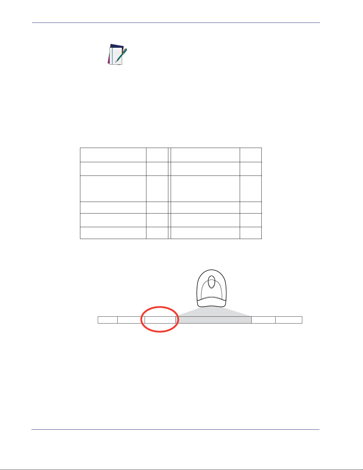
Data Editing
Global AIM ID
AIM label identifiers (as opposed to custom characters you select yourself as with label
identifiers) can be included with scanned barcode data. AIM label identifiers consist of
three characters as follows:
• A close brace character (ASCII ‘]’), followed by...
• A code character (see the table below), followed by...
• A modifier character (the modifier character is symbol dependent).
UPC/EAN
This feature enables/disables addition of AIM IDs for all symbology
types.
NOTE
SYMBOLOGY CHAR SYMBOLOGY CHAR
a
E
Code 128/GS1-128 C
Code 39 and
Code 32
A
GS1 DataBar Omnidirectional, GS1 DataBar
Expanded
Codabar F Standard 2 of 5 S
Interleaved 2 of 5 I ISBN
Code 93 G Code 11 H
a.
UPC-A and UPC-E labels are converted to EAN 13 when adding AIM IDs.
b.
ISBN (X with a 0 modifier character)
Figure 5. AIM ID
Prefix SuffixLabel ID Label IDBar Code DataAIM ID
e
b
X
92 QuickScan® QD2100
 Loading...