

Page 1

DLL2020
User’s Manual
Page 2

DLL2020
USER'S MANUAL
Page 3

DATALOGIC S.p.A.
Via Candini 2
40012 - Lippo di Calderara di Reno
Bologna - Italy
DLL2020 User's Manual
Ed.: 11/2003
ALL RIGHTS RESERVED
Datalogic reserves the right to make modifications or improvements without prior
notification.
Datalogic shall not be liable for technical or editori al errors or omissions contained
herein, nor for incidental or consequential damages resulti ng from the use of this
material.
Product names mentioned herein are for identification purposes only and may be
trademarks and or registered trademarks of their respective companies.
© Datalogic S.p.A. 2001 - 2003
820000884 (Rev. D)
Page 4

CONTENTS
INTRODUCTION................................................................... v
COMPLIANCE..................................................................... vi
FCC ..................................................................................... vi
Warranty ............................................................................. vi
1
1.1
1.2
1.3
1.4
1.5
1.6
2
2.1
2.1.1 RS232 Direct Power.............................................................. 10
2.1.2 Keyboard Wedge Direct Power............................................. 10
2.2
3
3.1
3.2
3.3
3.4
3.5
3.6
3.7
3.8
3.9
GETTING S TARTED............................................................... 1
Unpacking the DLL2020 .......................................................... 1
Available Models..................................................................... 2
Scanning Bar Codes with the DLL2020................................... 3
Scanner Labelling ...................................................................5
Maintaining the Scanner.......................................................... 7
Controlling the Scanner from the POS System........................ 8
INSTALLING THE DLL2020................................................... 9
Connecting the Scanner.......................................................... 9
Interface Selection................................................................ 11
CONFIGURATION................................................................ 13
Change Scanner Settings ..................................................... 13
Factory Default Settings........................................................ 14
Default Message Format....................................................... 15
Editing Commands................................................................ 16
RS232................................................................................... 17
RS232 Presets...................................................................... 17
Keyboard Wedge .................................................................. 19
PC/Terminal Type................................................................. 19
Keyboard Nationality............................................................. 20
Operating Parameters........................................................... 22
Code Selection...................................................................... 24
Data Formatting.................................................................... 27
Pre-defined Terminators........................................................ 27
Code Identifiers..................................................................... 28
iii
Page 5

A CONNECTOR AND PIN DEFINITIONS ................................ 30
B TECHNICAL FEATURES...................................................... 31
C TROUBLESHOOTING.......................................................... 33
iv
Page 6

INTRODUCTION
The Datalogic DLL2020 is a high perform ance omni-directional scanner,
which provides optimal sc anni ng conditions.
Together with its compact and ergonomic design, operator fatigue and
other discomforts are less than any competi tive omni-directional scanner.
These characteristics make the DLL2020 especially suitable for
installation in small counters such as in drugstores, pharmacies,
department stores, tobacconists, kiosks, petrol stations, and
convenience stores.
The omni-directional sc an field of the DLL2020 generat es a scan pattern
of 16 lines, ensuring high performance scanning. Featuring an
unequalled scan rate of 800 scans per second, the DLL2020 is an
aggressive scanner.
Barcodes are read simply on presentation to the scanner window.
However, the ergonomic design of DLL2020 rubber sleeve, which fits
naturally in the hand, makes the unit easy to pick up when larger or
heavier products have to be scanned.
The scanner con be installed ‘f ree-standing’ on a counter surface using
its protective rubber sleeve or without the s leeve, fl ush or s urfac e fixed to
check-out furniture, making for a very neat instal l ation.
This manual contains three chapters and three appendices. The first
chapter describes the DLL2020 sc anner, its general features as well as
the way in which it can be used. The precise ins truc t ions f or ins tall ing the
scanner are listed in the second chapter. Default settings can be
changed using the bar code labels in chapter 3 "Configuration".
Appendix A shows the connector types of the scanner. Technical
specifications of the DLL2020 can be found in Appendix B. Refer to
Appendix C for troubleshooting if the s canner is not working properly.
v
Page 7

COMPLIANCE
FCC
This equipment has been tested and found to com ply with the limits for a Class B
digital device, pursuant to EN55022, and with the limi ts for a class A digital device,
pursuant part 15 of the FCC rules. These limi ts are designed to provide reasonable
protection against harmful interference when the equipment is operated in a
commercial environment. This equipment generates, uses, and can radiate radio
frequency energy and, if not installed and used in accordance with the user's manual,
may cause harmful interference to radio communications. Operation of the
equipment in a residential area is li kely to cause harmful interference in which case
the user will be required to correct the interference at his own expense. Any
unauthorized changes or modifications to this equipment could void the user's
authority to operate this equipment.
For CE-countries:
-
The DLL2020 is in conformity with the CE standards.
For USA & Canada:
-
To be used with UL listed and CSA certified computers/POS systems.
-
À utiliser avec des ordinateurs/systèmes POS registrés UL/certifiés CSA.
Radio and Television Interference
Operation of this equipment in a residential area can cause interference to radio or
television reception. This can be determined by turning the equipment off and on.
The user is encouraged to try to correct the interference by one or more of the
following measures:
• Re-orientate the receiving antenna
• Relocate the device with respect to the receiver
• Move the device away from the receiver
• Plug the device into a different outlet in order to have the device and
WARRANTY
Datalogic warranties this product against defects in workmanship and materials, for a
period of 24 months from the date of shipment, provided that the product is operated
under normal and proper conditions.
Datalogic has the faculty to repair or replace the product, these provisions do not
prolong the original warranty term.
The warranty does not apply to any product that has been subject to misuse,
accidental damage, unauthorized repair or tampering.
receiver on different branch circuits.
vi
Page 8
GETTING STARTED
1
1 GETTING STARTED
1.1 UNPACKING THE DLL2020
Take the scanner and its accessories out of the box and remove all
packing material s. Refer to the packing lis t in order to ensure that you
have received all the items ordered. Visually inspect the scanner and
accessories for any visible traces of damage. Refer to the figure in
paragraph 1.4 to locate the interface label and verify if the scanner
interface corresponds with the host system interface. Immediately
contact your supplier if anything appears to be damaged, or if the
supported interface does not correspond with the host system interface.
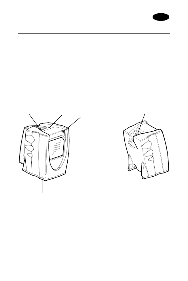
Green Led
Red Led
Good read beeper
Sleep mode switch
Rubber sleeve
1
Page 9
1
The various parts of the DLL2020 are:
Sleep mode switch: If a s leep mode time-out has been programmed,
the scanner can be reactivated by pres sing this switch. The sleep-mode
feature can be programmed us ing the Software Configurat ion Guide part
number 90ACC1620.
The default value for the sleep mode time-out is set to
30 minutes. When the sc anner is in sleep mode, the
LED is intermittently flashing red.
NOTE
Red LED: The red LED indicates that the scanner is ready to read a bar
code.
Green LED: The green LED indicates a good read.
Good read beeper: The beeper sounds whenever data have been
correctly read. The frequency can be adjusted using the Software
Configuration Guide part number 90ACC1620.
Rubber sleeve: A rubber sleeve encloses the scanner. The sleeve
protects the s canner, and t akes care that i t does not s lide when instal led
‘free-standing’ on a counter surf ace. Furthermore, its ergonomic design
makes the unit eas y t o pi ck up; it fits nat ural l y i n the hand.
DLL2020
1.2 AVAILABLE MODELS
The following two models are available:
− DLL2020, standard model
− DLL2021, with single line option (see par. 3.7 for detai l s).
2
Page 10
GETTING STARTED
1
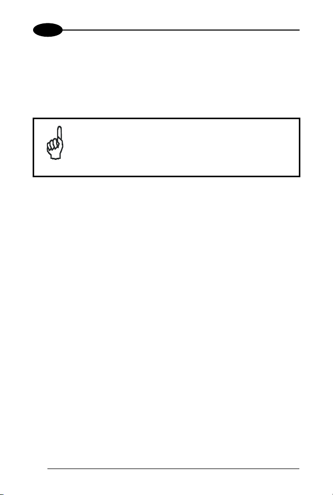
1.3 SCANNING BAR CODES WITH THE DLL2020
15 cm
15 cm
25 cm
X
The DLL2020 is an om ni di rectional scanner featuring a 4-directional scan
field with a 16-line scan pattern. Bar codes can easily be read by
presenting them to the scanner. The scan volume is illustrated in the
figure above. The optimal reading zone li es between 3 and 15 cm from
the scanner window. However, bar codes can s till be read up to 25 cm
(10 inches) from the scanner window.
Z
3 cm
3
Page 11
1
DLL2020
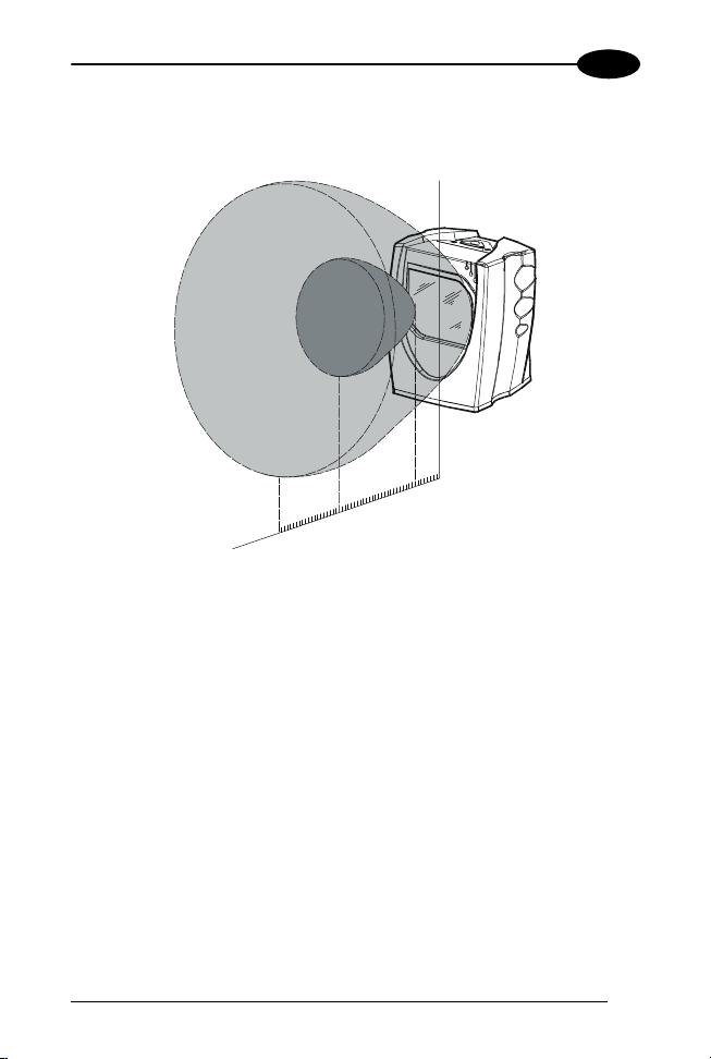
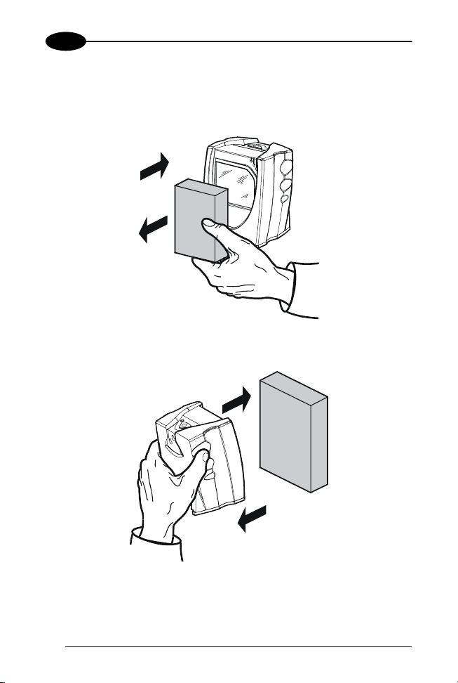
The DLL2020 scanner can be used handsfree as well as hand held,
e.g.:
a) Handsfree scanning by presenting t he i tem to the scanner.
1
1
2
2
b) You can also hold the scanner.
4
1
1
2
2
Page 12
GETTING STARTED
1
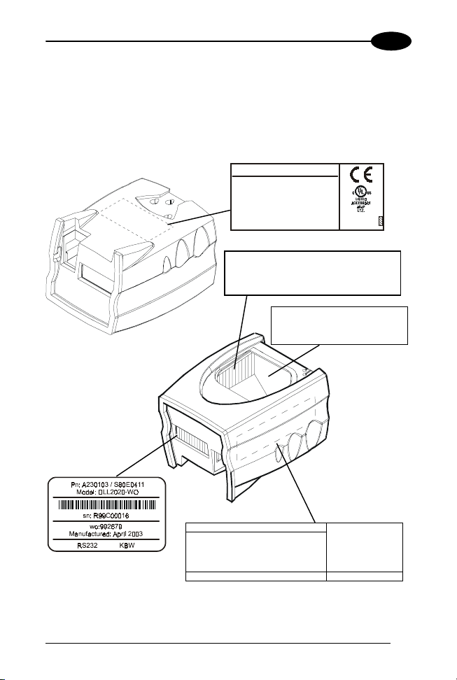
1.4 SCANNER LABELLING
There are four labels on the scanner. The f irst three labels can be found
on the housing of the DLL2020, as indic ated in the figures below. The
fourth label is visible through the scanner window.
All the labels have been attached by the manufac turer and should in no
case be removed.
DATALOGIC SPA - ITALY
CAUTION:
Laser light when open
Do not star e into beam
EN60825-1 (2001) CLASS 1 LASER PRODUCT
Complies with 21 CFR subchapter J as a
CLASS IIA LASER PRODUCT -
avoid long term viewing of direct laser light
+5V
250mA
CAUTION
Laser Radiation When Open
DO NOT STARE INTO BEAM
DO NOT BREAK SEAL
WARRANTY VOID IF SEAL IS BROKEN
NO SERVICEABLE PARTS INSIDE Model DLL2020-W O
DATALOGIC SPA
Via Candini 2
40012 LIPPO DI-
CALDERARA (BO)
ITALY
www.datalogic.it
5
Page 13

1
The scanner’s seri al num ber c an be found under t he bar code label . This
official regist ration number is strictly relat ed to the device. The supplier
may ask for this number when the scanner needs servicing.
DLL2020
Laser safety
English:
The DLL2020 scanner complies with s afety standard EN60825-1 (2001)
for a Class 1 laser product. It also complies with U.S. 21CFR1040 as
applicable to a Class II a laser product. Avoid long term viewing of direct
laser light.
German:
Der Strichcode-Scanner DLL2020 ents pricht den Sicherheitsvorschrif ten
nach EN60825-1 (2001) für ein Laserprodukt der K lasse 1. Er ent spricht
auch U.S. 21CFR1040, anwendbar auf ein Laserprodukt der Klasse II a.
Vermeiden Sie langzeitiges Hineinblicken in direktes Laserlicht.
French:
Le scanner DLL2020 est conforme aux normes de sécurité
EN60825-1 (2001) s’appliquant à un produit laser de la class e 1. Il est
également conform e à la U.S. 21CFR1040 telle qu’ell e s’applique à un
produit laser de la classe IIa. Eviter de rester exposé longtemps à la
lumière directe du laser.
Italian:
Lo scanner DLL2020 è conforme alle norme di sicurezza EN60825-1
(2001) relative ad un prodot to laser di Classe 1. È inoltre conforme alla
norma U.S. 21CFR1040 relativa ad un prodotto laser di Classe IIa.
Evitare l’esposizione prolungata all’emissione diretta di luce laser.
Spanish:
El scanner DLL2020 reune las normas de seguridad EN60825-1 (2001)
para un producto laser de Clase 1. Y también reune las normas U.S.
21CFR1040 que se aplican a un producto laser de Clase IIa.
Se debe evitar mirar muy fijo en luz lasérica direct a.
Optical The use of optical instrum ents with this product will increase eye
hazard. Optical instruments include binoculars, microscopes and
magnifying glasses but do not include eye glasses worn by the user.
6
Page 14

GETTING STARTED
Radiant Energy The DLL2020 uses a low-power laser diode operating
at 650 nm in an opto-mechani cal scanner resulting i n less than 0.7 mW
peak output power.
Laser light observed at 15. 0 cm (5. 9 inch) above the window through a 7
mm (0.28 in.) aperture and averaged over 1000 s econds is less than 3.9
µW per CDRH Class IIa specification. Do not attempt to remove the
protective housing of the scanner, as unsc anned laser light with a peak
output up to 0.90 mW could be accessibl e i nside.
Laser Light Viewer The sc anner window is the only aperture through
which laser light may be observed on t his product.
A failure of the scanner m otor, while the laser diode conti nues to emit a
laser beam, may cause emission levels to exceed those for safe
operation.
The scanner has safeguards to prevent this occurrence. If, however, a
stationary laser beam is emitted, the failing scanner should be
disconnected from i ts power source immediat el y.
Adjustments Do not att empt t o mak e any adjustm ents to or alterat ion of
this product. Do not remove the s canner’s protect ive housing. There are
no user-serviceable parts ins i de.
Use of controls or adjustments or performance of
procedures other than those specified herein may
result in hazardous laser light exposure.
CAUTION
1
1.5 MAINTAINING THE SCANNER
The DLL2020 scanner requires little maintenance. Only occasional
cleaning of the scanner window is necess ary in order to remove dirt and
fingerprints. The scanner c an be cleaned during operation. To this end
use a non-abrasive glass spray cl eaner and a soft lint-free cloth onl y.
7
Page 15

1
DLL2020
1.6 CONTROLLING THE SCANNER FROM THE POS SYSTEM
The DLL2020 can be controlled from the POS system via the RS232
interface. Controlling is accomplished by transmitting the following si nglebyte commands to the scanner. In the Datalogic default setting the
following commands are avai l abl e (more details upon request):
Command Description Hex.
Ctrl - E Power-up re-initialization 05 Hex
Ctrl - N Enable decoding 0E Hex
Ctrl - O Disable decoding 0F Hex
Ctrl - R Sleep 12 Hex
Ctrl - T Wake 14 Hex
When the scanner dec oding is disabled, the scanner motor will remain
switched-on until the scanner goes i nto sleep mode.
POS system
DLL2020
Scanner control
8
Page 16

INSTALLING THE DLL2020
2
2 INSTALLING THE DLL2020
2.1 CONNECTING THE SCANNER
This chapter describes the instructions necessary for installing the
DLL2020 scanner.
Due to many POS systems on the market, a large number of
communication cables is available. Make sure that you have the right
cable to connect the scanner to your POS or computer.
The scanner and the host system must be switched off
before starting the installation of the scanner. By
following this precaution you prevent any electrical
damage.
NOTE
Follow these steps carefully in order to install the scanner:
1. Locate the optimal scanner position in relation to the counter
surface.
Pay attention to the product flow, the distance to the counter edge
and convenience for the operator.
2. You have two options to connect the scanner to your POS or
computer.
You are advised to install the scanner in an air
circulated place out of di rect sunlight.
9
Page 17

2
DLL2020
2.1.1 RS232 Direct Power
For those systems which supply electrical power on the serial port
(minimal requirements: +5 V dc, 250 mA), the following setup is
applicable.
Plug the cab 376 into the sc anner port until a firm ‘click’ is heard.
Connect the serial cable to the cab 376 and the other end to the
appropriate serial port of your POS or computer.
DLL2020
Cable 376
To host
2.1.2 Keyboard Wedge Direct Power
For those systems which supply electrical power on the keyboard port
(minimal requirements: +5 V dc, 250 mA), the following setup is
applicable.
Plug the cab 376 into the sc anner port until a firm ‘click’ is heard.
Connect the wedge cable to the cab 376 and the other end to the
keyboard.
10
DLL2020
Cable 376
To computer
To keyboard
Computer
Page 18
INSTALLING THE DLL2020
2
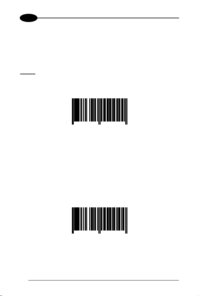
2.2 INTERFACE SELECTION
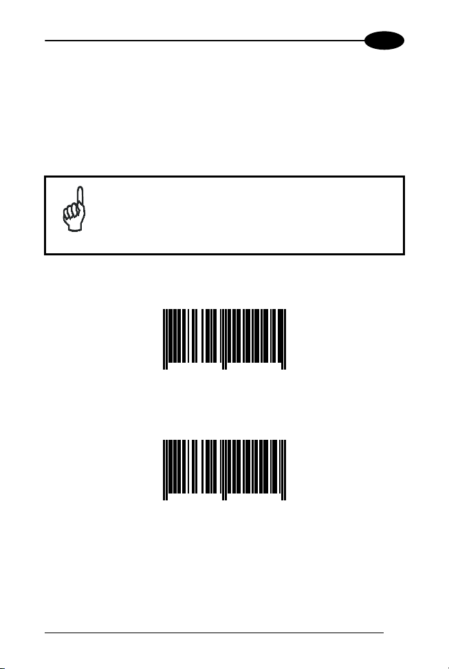
To select the scanner int erf ace scan the following codes:
1. read the "Enter/Exit and Save Programming Mode" code;
2. scan either "RS232 default" code or "Keyboard Wedge default"
code.
RS232 is the factory default interface.
NOTE
Enter/Exit and Save Programming Mode
8 712345 100001
RS232 Default
8 712345 100100
Programming Mode is cl osed after scanning this c ode.
11
Page 19

2
Keyboard Wedge Default
DLL2020
8 712345 100131
Programming Mode is cl osed after scanning this c ode.
12
Page 20
CONFIGURATION
3
3 CONFIGURATION
The present manual provides information on how to set the
DLL2020 reader in operation, as wel l as to set up its basic
configuration parameters.
Additional customized configurations are also available
NOTE
3.1 CHANGE SCANNER SETTINGS
In order to change the scanner settings please follow the sequence
below:
1. Enter the scanner P rogramming Mode by scanning the Enter/Exit
2. Change Scanner Settings by scanning the desired codes from
3. Exit the scanner Programming Mode by scanning the Enter/Exit
Reading the Enter/Exit code in par. 3.4 gives a double tone beep (Low
High).
Example:
For changing the keyboard to German the following codes must be
scanned success i vel y:
"Enter/Exit and Save Programming Code", "German", "Enter/Exit and
Save Programming Code".
After reading a valid configuration barcode in Programming Mode the
scanner will give a High beep.
The scanner will generate a Low beep after receiving an unexpected
code.
At any moment (in Programming Mode) you can scan the "Return to
Factory Default Settings" code to return to default s ettings.
by changing basic parameters: please refer to the
Software Configuration Manual (Part No. 90ACC1620)
for a complete list of codes and procedures.
code (see par. 3.4);
par. 3.5 to par. 3.9.
code in par. 3.4.
13
Page 21

3
3.2 FACTORY DEFAULT SETTINGS
DLL2020
Configuration Field Default Setting
Sleep Mode
Sleep mode After 30 minutes
Scanner Timing
Same code delay 600 msec
RS232
Baudrate 9600
Parity None
Data bits 8
Stop bits 2
RTS/CTS Off
Terminator <CR>
Keyboard Wedge
PC Terminal type PC/AT
Keyboard International (Alt method)
Caps Lock OFF
Intercharacter delay 2 msec
Terminator Enter (Alphanumeric)
Operating Parameters
Freeze Frame disabled
Single Line(DLL2021 models only) disabled
Code Selection
EAN/UPC On (ADD ON not sent)
Code 128/EAN 128 Off
Code 39 Off
Code 32 Off
Codabar Off
Interleaved 2/5 Off
Code Length
Min. length Interleaved 2/5 8
Data Formatting
Code Identifiers Off
14
Page 22

CONFIGURATION
3.3 DEFAULT MESSAGE FORMAT
Code Message Format
EAN13 D1 D2 D3 D4 D5 D6 D7 D8 D9 D10 D11 D12 D13
EAN8 D1 D2 D3 D4 D5 D6 D7 D8
UPCA D1 D2 D3 D4 D5 D6 D7 D8 D9 D10 D11 D12
UPCE D1 D2 D3 D4 D5 D6 D7
Code 128 D1 - Dx
EAN 128 ]C1 D1 - Dx
Code 39 D1 - Dx
Code 32 D1 - Dx
Codabar D1 - Dx
Interleaved 2/5 D1 - Dx
EAN/UPC codes wit h ADD ON are transmitted without
a separator.
NOTE
3
15
Page 23

3
3.4 EDITING COMMANDS
Enter/Exit and Save Programming Mode
DLL2020
8 712345 100001
Restore Factory Default
8 712345 100087
Return to Custom Default Setting s
8 712345 100070
16
Page 24

CONFIGURATION
3
3.5 RS232
RS232 Presets
Each of the following barcode selections enable a complete preset
parameter configuration for correct use with the respective POS
Terminal.
The scanner must first be set with the RS232 interface selec tion (see
par.2.2).
Wincor Nixdorf Beetle Mode A1
8 712345 190101
Wincor Nixdorf Beetle Mode A2
8 712345 190118
Wincor Nixdorf Beetle Mode B1
8 712345 190125
17
Page 25
3
Wincor Nixdorf Beetle Mode B2
DLL2020
8 712345 190132
Wincor Nixdorf Beetle Mode B3
8 712345 190149
ICL Mode
8 712345 200008
Fortronic (UK) Mode
8 712345 200107
18
Page 26

CONFIGURATION
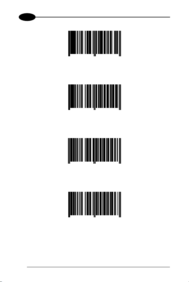
3.6 KEYBOARD WEDGE
PC/Terminal Type
PC/XT
3
8 712345 400002
PC/AT (Default)
8 712345 400019
PC PS2
8 712345 400026
IBM 347 x terminals
8 712345 400033
19
Page 27

3
IBM 3179 x terminal
DLL2020
8 712345 400040
Keyboard Nationality
International Keyboard (ALT Method)(Default)
8 712345 400200
8 712345 400217
US
UK
20
8 712345 400224
Page 28

CONFIGURATION
3
French
8 712345 400231
German
8 712345 400248
Spanish
8 712345 400255
21
Page 29
3
3.7 OPERATING PARAMETERS
Scanning Mode
Two different options are available to defi ne t he scanning mode:
− Freeze Frame mode;
− Single Line mode;
reading the code enabling the desired mode it is necessary to
Before
read the following code starting the procedure:
Scanning Mode
DLL2020
8 712345 150020
Freeze Frame Mode
The Freeze Frame m ode is a special trigger mode allowing to aim t he
laser pattern on the code before reading.
To work in this mode:
1. Press the DLL2020 trigger. The laser pattern starts blinking but the
scanner does not read the code;
2. Move the scanner towards the barcode (zoom-in);
3. Release the scanner trigger to read the barcode.
Freeze Frame ON
8 712345 150044
22
Page 30

CONFIGURATION
Single Line Mode (DLL2021 only)
The single line option allows tem porarily switching from full scan pattern
to a single scan line preventing the wrong barcode to be read. This
feature is especially helpful on sheets or products where multiple
barcodes are printed.
To use this option proceed as f ol l ows:
1. Press the button on top of the scanner t o switch from the full scan
pattern to a single scan li ne;
2. Aim t he singl e sc an line on t he barcode t o be scanned while holding
the button;
3. Make the line to completely cross the barcode, then release the
button. A beep indicates the barcode has been accepted by the
scanner;
4. After successful reading the s ingle line blinks. During the scan line
blinking, the scanner will not read a barcode. Af ter one second, the
scanner will return to normal m ode. I f pres sing t he trigger during t he
scan line blinking, the single line procedure will start again.
Single Line ON
3
8 712345 150051
23
Page 31

3
3.8 CODE SELECTION
All EAN/UPC ON (ADD ON not sent) (Default)
DLL2020
8 712345 141011
All EAN/UPC OFF
8 712345 141004
Code 128/EAN 128 ON
8 712345 143107
Code 128/EAN 128 OFF
8 712345 143114
24
Page 32

CONFIGURATION
3
Code 39 ON
8 712345 143015
Code 39 OFF
8 712345 143053
CODABAR ON
8 712345 143022
CODABAR OFF
8 712345 143060
25
Page 33

3
Interleaved 2/5 ON
DLL2020
8 712345 142025
Interleaved 2/5 OFF
8 712345 142001
26
Page 34

CONFIGURATION
3
3.9 DATA FORMATTING
Pre-defined Terminators
To program the terminator string follow the given procedure:
1) If not working in Programming Mode, s can the "Enter/Exit and Save
Programming Mode" code;
2) Choose the desired pre-defined term i nator from the list below
3) Scan the "Enter/Exit and Save Programming Mode" code OR
configure other parameters.
Terminator = CR
8 712345 110505
Terminator = LF
8 712345 110611
Terminator = CR + LF
8 712345 110512
27
Page 35

3
DLL2020
Code Identifiers
A code identifier is a dat a string, giving information to the host system
concerning the barcode type that has been read After scanning the
"Enable Default Code Identifiers" code, the scanner is configured to
transmit data according to the following format:
CODE CODE IDENTIFIER MESSAGE FORMAT
EAN13 F D1 D2 D3 D4 D5 D6 D7 D8 D9
EAN8 FF D1 D2 D3 D4 D5 D6 D7 D8
UPCA A D1 D2 D3 D4 D5 D6 D7 D8 D9
UPCE E 0 D1 D2 D3 D4 D5 D6
Code 128 # D1 Dx
EAN 128 P ]C1 D1 Dx
Code 39 * D1 Dx
Code 32 * D1 Dx
Codabar % D1 Dx
Interleaved 2/5 i D1 Dx
The UPCE format will be changed. The scanner will
transmit UPCE codes wi th leading 0 and w ithout c heck
digit.
NOTE
To return to the default form at without code identifi ers read the "Disable
Code Identifiers" code.
D10 D11 D12 D13
D10 D11 D12
28
Page 36

CONFIGURATION
3
Enable Default Code Identifiers
8 712345 110475
Disable Code Identifiers
8 712345 110468
29
Page 37

A
CONNECTOR AND PIN DEFINITIONS
A
The DLL2020 has a dual interface: RS232/Keyboard Wedge. The pin
definition for the scanner port and the connector to be used for the port
are shown in the connection diagram below.
PIN DESCRIPTION
Pin 1
RJ-48 PCB
(front view)
Scanner port
NOTE
Pin 10
Use approved Datalogic cables onl y.
1 PC - CLOCK
2 CTS
3 RXD
4 TXD
5 RTS
6 GND
7 +5V
8 KB - DATA
9 KB - CLOCK
10 PC - DATA
Pin 1
RJ-48 Cable-connect o r
(front view)
10 pin connector
DLL2020
Pin 10
Slot for screwdriver
30
1
2
Locking pin
Page 38

TECHNICAL FEATURES
TECHNICAL FEATURES
B
Electrical Features
Input power to scanner +5 Vdc t o +5. 25 Vdc, 250 mA
Dual interface RS232/Keyboard W edge
Adapter Cable Cab 376
Optical Features
Light source Visibl e l aser diode (650 nm)
Depth of field 250 mm
Scan pattern 4 directions, 16 lines
Scan rate 800 scans/seconds
Decoding Features
Barcode types EAN/UPC/JAN + Add ON
Code 128, EAN 128, Code 39, Code 32,
Codabar, ITF
B
31
Page 39

B
S
Physical Features
Weight 0.3 kg
Dimensions
(L x W x D)
Front view
100 x 80 x 60 mm
3.9 x 3.1 x 2.4 in
ide view
98.8 mm
DLL2020
8.00°
78.2 mm
Environmental Features
Operating Temperature 0° to + 40 °C
Humidity 0% to 95% RH (non-condensing)
Safety Features
Laser safety EN60825-1 (2001) class 1, U.S. 21CFR1040
Class Ila
Electrical safety EN 60950 second edition UL1950 (third
edition), c-UL (according CSA22.2.950-95)
EM Compatibility
Radio and TV interference EN 55022 Class B (1994), FCC
part 15 Class A (1992)
Harmonic current emi ssions EN 61000-3-2 (1995)
EM-immunity EN 50082-1 (1992) based on:
ElectroStatic Discharge (ESD) IEC 801-2 (1991)
Radio frequency immunity IEC 801-3 (1984) / ENV 50140
(1993)
Electrical fast transient IEC 801-4 (1998)
32
Page 40

TROUBLESHOOTING
TROUBLESHOOTING
C
Problem Diagnostic Tips
The scanner is on but a
barcode cannot be read. The
LED is red.
The scanner is on, but the
motor is not rotating. A
barcode cannot be read. The
LED is intermittently flashing
red.
The red LED and green LED
are alternating.
The red LED and green LED
are alternating and beeps are
heard.
The scanner does not accept
more than two or three
barcodes.
Both the red LED and green
LED are on.
C
• The scanner window is dirty. Clean
the scanner window as described
in the Maintenance section.
• The presented barcode type is not
enabled. Select the barcode type
with the Configuration Guide.
• The scanner is disabled by the
host. Refer to par. 1.6.
• The barcode type you presented to
the scanner is not supported by
DLL2020.
• The scanner is in sleep mode.
Press the switch on top of the
scanner to reactivate the scanner
(or use the wake protocol. Refer to
par. 1.6).
• Mirror motor is defective and m ust
be replaced (Authorized personnel
only).
• Possible failure of the scanning
safeguard circuit. Immediately
disconnect the scanner from its
power source. Contact your
supplier.
• There is no proper handshaking
with the host system. Switch the
host system on and check
connection and communication
settings.
• The laser is not functioning. The
laser is defective. Contact your
supplier.
33
Page 41

C
Problem Diagnostic Tips
Both the red LED and green
LED are blinking.
The green LED stays on.
A barcode is read by the
scanner but not accept ed by
the host system.
DLL2020
• The ambient temperature is too
high. Make sure the scanner has
enough air ventilation and is not
placed in direct sunlight.
• The scanner is continuously seeing
a barcode. Remove all barcode
labels from the sc an volume of the
scanner and try again.
• The scanner cannot send the data
to the host system. There is no
proper handshaking between the
scanner and the host. Scanner
buffer is full. Make sure that all
cables are connected and your
host system is ready to receive
data.
• The scanner is in test mode.
Power off and on the scanner.
• The communication cable is not
connected to the seri al port of your
host system. Refer to the manual
of your host system to locate the
serial port.
• The communication sett ings of the
host and scanner do not match.
Ensure that the setting value for
both devices are the same. For
proper adjustment values see the
Software Configuration Guide.
• The communication cabl e does not
suit your host system. Contact your
supplier for the correct
communicati on cable.
• The data format is not supported
by the software running on the host
system.
34
Page 42

DATALOGIC S.p.A.,
Via Candini, 2
40012 - Lippo di Calderara
dichiara che
declares that the
déclare que le
bescheinigt, daß das Gerät
declare que el
DLL202X-XX Presentation Scanner
e tutti i suoi modelli
and all its models
et tous ses modèles
und seine modelle
y todos sus modelos
sono conformi alle Direttive del Consiglio Europeo sottoelencate:
are in conformity with the requirements of the European Council Directives listed below:
sont conformes aux spécifications des Directives de l'Union Européenne ci-dessous:
den nachstehenden angeführten Direktiven des Europäischen Rats:
cumple con los requisitos de las Directivas del Consejo Europeo, según la lista siguiente:
89/336/EEC EMC Directive e 92/31/EEC, 93/68/EEC emendamenti successivi
and further amendments
et ses successifs amendements
und späteren Abänderungen
y succesivas enmiendas
Basate sulle legislazioni degli Stati membri in relazione alla compatibilità elettromagnetica ed alla
sicurezza dei prodotti.
On the approximation of the laws of Member States relating to electromagnetic compatibility and
product safety.
Basées sur la législation des Etates membres relative à la compatibilité électromagnétique et à la
sécurité des produits.
Über die Annäherung der Gesetze der Mitgliedsstaaten in bezug auf elektromagnetische
Verträglichkeit und Produktsicherheit entsprechen.
Basado en la aproximación de las leyes de los Países Miembros respecto a la compatibilidad
electromagnética y las Medidas de seguridad relativas al producto.
Questa dichiarazione è basata sulla conformità dei prodotti all e norme seguenti:
This declaration is based upon compliance of the products to the following standards:
Cette déclaration repose sur la conformité des produits aux normes suivantes:
Diese Erklärung basiert darauf, daß das Produkt den folgenden Normen entspricht:
Esta declaración se basa en el cumplimiento de los productos con las siguientes normas:
EN 55022, August 1994: L
EN 55024, September 1998: I
Lippo di Calderara, 25/06/2001
Ruggero Cacioppo
Quality Assurance Supervisor
Bologna - Italy
IMITS AND METHODS OF MEASUREMENTS OF RADIO
DISTURBANCE CHARACTERISTICS OF INFORMATION
TECHNOLOGY EQUIPM E NT
NFORMATION TECHNOLOGY EQUIPMENT, IMMUNITY
CHARACTERISTICS
MEASUREMENTS
(ITE)
IMITS AND METHODS OF
. L
 Loading...