

Page 1

DX8200 Controller
Reference Manual
Page 2

Page 3

DX8200 Controller
INSTALLATION MANUAL
Page 4

DATALOGIC S.p.A.
Via Candini 2
40012 - Lippo di Calderara di Reno
Bologna - Italy
DX8200 Controller
Ed.: 10/2004
ALL RIGHTS RESERVED
Datalogic reserves the right to make modifications or improvements without prior notification.
Datalogic shall not be liable for technical or editorial errors or omissions contained herein, nor for
incidental or consequential damages resulting from the use of this material.
Product names mentioned herein are for identification purposes only and may be trademarks and or
registered trademarks of their respective companies.
© Datalogic S.p.A. 2000 - 2004
20/10/04
Page 5

CONTENTS
GUIDE TO INSTALLATION........................................................................................v
GENERAL VIEW.......................................................................................................vi
SAFETY PRECAUTIONS........................................................................................viii
Electrical Safety ........................................................................................................viii
Laser Safety..............................................................................................................viii
Power Supply............................................................................................................. ix
1 GENERAL FEATURES..............................................................................................1
1.1 Introduction.................................................................................................................1
1.1.1 Indicators ....................................................................................................................3
1.2 Model Description .......................................................................................................3
1.3 Accessories ................................................................................................................3
1.4 Applications ................................................................................................................4
2 INSTALLATION..........................................................................................................5
2.1 Package Contents.......................................................................................................5
2.2 Mechanical Installation................................................................................................6
2.3 Electrical Connections.................................................................................................7
2.3.1 Power Supply..............................................................................................................7
2.3.2 Ethernet......................................................................................................................8
2.3.3 Host Interface .............................................................................................................8
Main Interface .............................................................................................................9
Auxiliary Interface .....................................................................................................12
2.3.4 Lonworks ..................................................................................................................12
2.3.5 RS232 Debug ...........................................................................................................13
2.3.6 Inputs........................................................................................................................13
2.3.7 Outputs.....................................................................................................................14
2.4 Layouts.....................................................................................................................15
3 SOFTWARE CONFIGURATION...............................................................................16
3.1 Genius™ Installation.................................................................................................16
3.2 Guide to Configuration ..............................................................................................16
3.3 Advanced Genius™ Configuration ............................................................................17
3.4 Parameter Default Values .........................................................................................18
4 READING FEATURES.............................................................................................21
4.1 Advanced Code Reconstruction................................................................................21
4.2 PackTrack™ .............................................................................................................22
4.3 Performance .............................................................................................................23
4.3.1 Reading Conditions...................................................................................................23
4.4 Reading Diagrams ....................................................................................................25
5 MAINTENANCE .......................................................................................................37
5.1 Cleaning....................................................................................................................37
5.2 Automatic Scanner Replacement..............................................................................37
5.3 Replacing the Protection Fuses (for AC Models).......................................................38
6 TECHNICAL FEATURES.........................................................................................39
iii
Page 6

GLOSSARY..............................................................................................................41
INDEX....................................................................................................................... 44
iv
Page 7

GUIDE TO INSTALLATION
The following can be used as a checklist to verify all the necessary steps for complete
installation of the DX8200 Controller.
1. Read all information in the section Safety Precautions at the beginning of this manual.
2. Correctly position and mount the scanner for barcode reading according to the
information in par. 4.4.
3. Make electrical connections to your DX8200 Controller by:
a) correctly wiring the DX8200 Controller to the Host using one of the desired Host
interfaces: Ethernet, Main or Aux Serial port communication, see par. 2.3.2 and 2.3.3.
b) correctly wiring the Encoder and External Trigger (Presence Sensor) inputs as well
as any output devices to the DX8200 Controller signals, see par. 2.3.6 and 2.3.7.
c) completing the system wiring adding as many slave scanners as required by your
system layout (refer to par. 2.4).
d) correctly inserting either the BTK-8000 terminator or the CAB-8305 cable in the last
Slave reader of the network as shown in par. 2.4.
4. Configure the DX8200 Controller (Master) scanner by using the Genius™ program.
5. Configure the Slave scanners using the onboard program through HyperTerminal: The
main parameters are:
• defining each slave scanner address
• selecting the codes to be read
• selecting data formatting
The installation is now complete.
v
Page 8
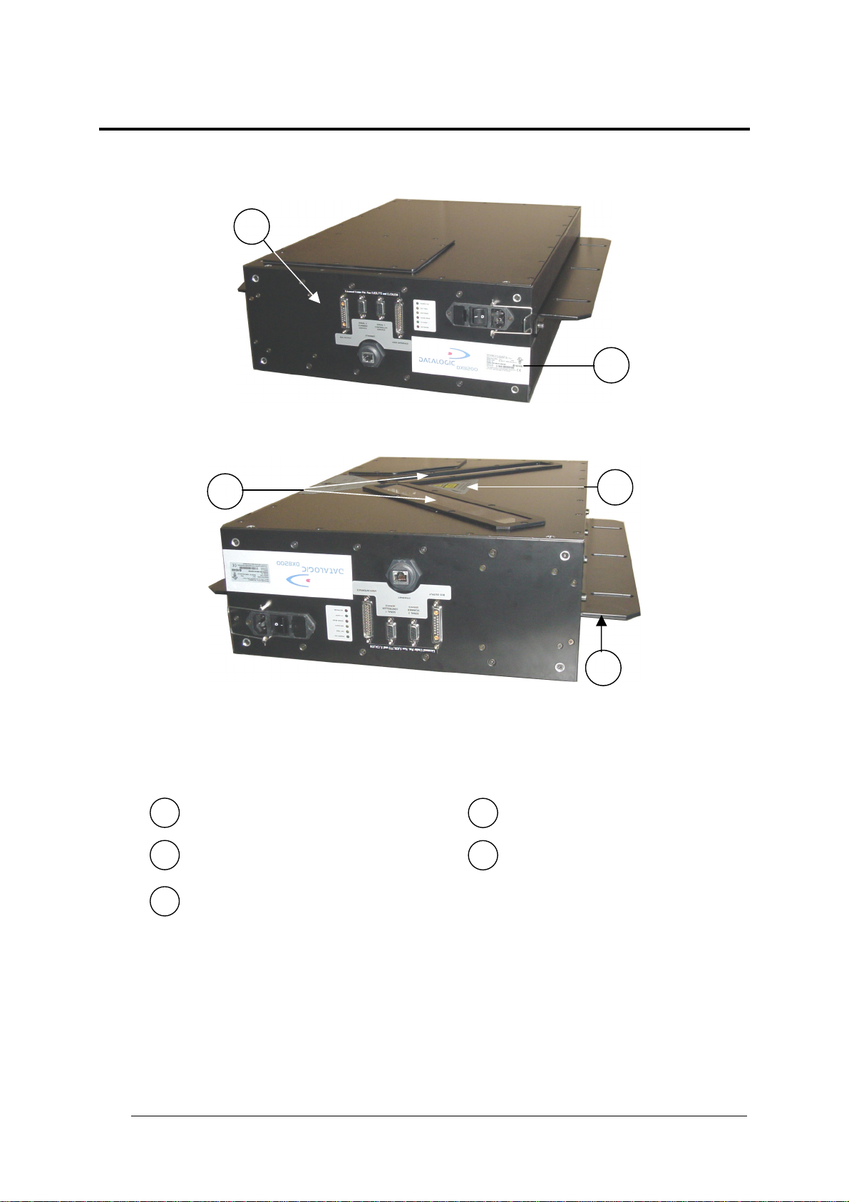
GENERAL VIEW
1
DX8200 Controller
2
5
4
3
Figure A - DX8200 Controller General View
Control Panel (see Figure B)
1
Product Label
2
Laser Warning Label
4
Mounting Rails
5
Laser Output Windows
3
vi
Page 9
6
7 8
9
10
11
12
5
4
3
2
1
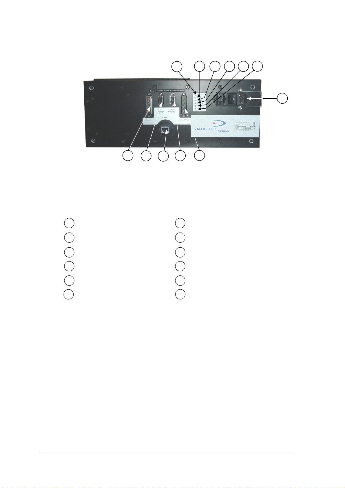
Figure B – Control Panel
Host Interface Connector
1
Presence Sensor LED (N.A.)
7
Reserved Connector
2
Ethernet connector
3
RS232 Debug Connector
4
Lonworks Network Connector
5
Power ON LED
6
Encoder LED
8
Good Read LED
9
TX Data LED
10
Network LED
11
VAC Power Panel (for VAC models only)
12
Fuses, Power Switch, Power Connector,
vii
Page 10
SAFETY PRECAUTIONS
ELECTRICAL SAFETY
This product conforms to the applicable requirements contained in the European
Standard for electrical safety EN-60950-1 at the date of manufacture.
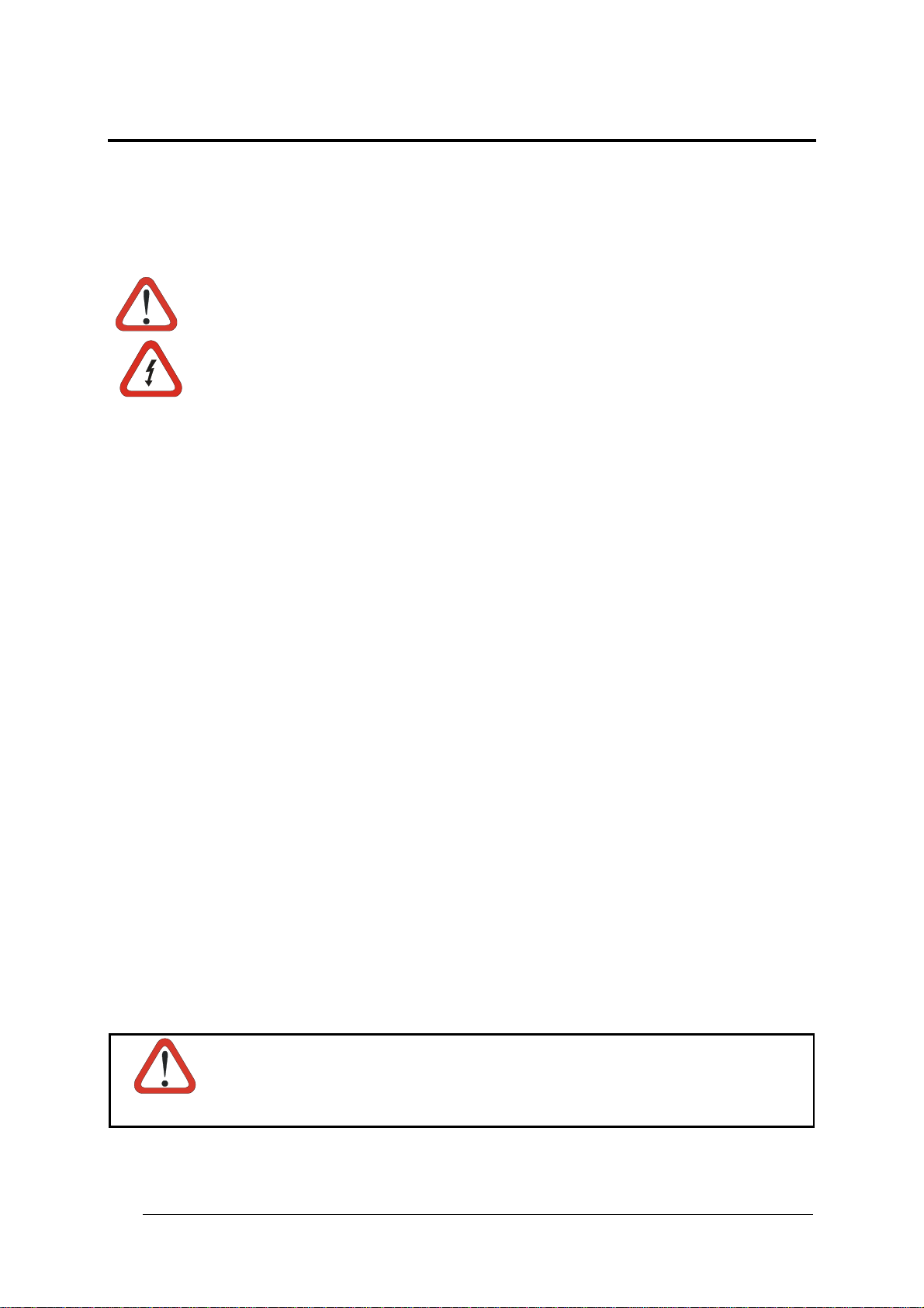
This symbol refers to operations that must be performed by qualified personnel
only. Example: opening the device.
This symbol refers to operations where there is danger of electrical shock. Before
opening the device make sure the power cable is disconnected to avoid electric
shock.
This device must be installed to a power source equipped with on/off switch or
breaker within range of the operator as protection against grounding failures.
This device is protected against overloading by correct value fuses. For
protection fuse replacement make sure correct value fuses are installed. See the
fuse selection table in par. 5.2.
For AC models
LASER SAFETY
The following information is provided to comply with the rules imposed by international
authorities and refers to the correct use of the DX8200 Controller scanner.
Standard Regulations
This scanner utilizes up to 3 low-power laser diodes. Although staring directly at the laser
beam momentarily causes no known biological damage, avoid staring at the beam as one
would with any very strong light source, such as the sun. Avoid that the laser beam hits the
eye of an observer, even through reflective surfaces such as mirrors, etc.
This product conforms to the applicable requirements of both EN 60825-1 and CDRH 21
CFR 1040 at the date of manufacture. The scanner is classified as a Class 2 laser product
according to EN 60825-1 regulations and as a Class II laser product according to CDRH
regulations.
There is a safety device which allows the laser to be switched on only if the motor is rotating
above the threshold for its correct scanning speed.
WARNING
viii
Use of controls or adjustments or performance of procedures other than
those specified herein may result in exposure to hazardous visible laser
light.
Page 11
The laser light is visible to the human eye and is emitted from the windows on the lower side
of the reader (Figure A, 3).
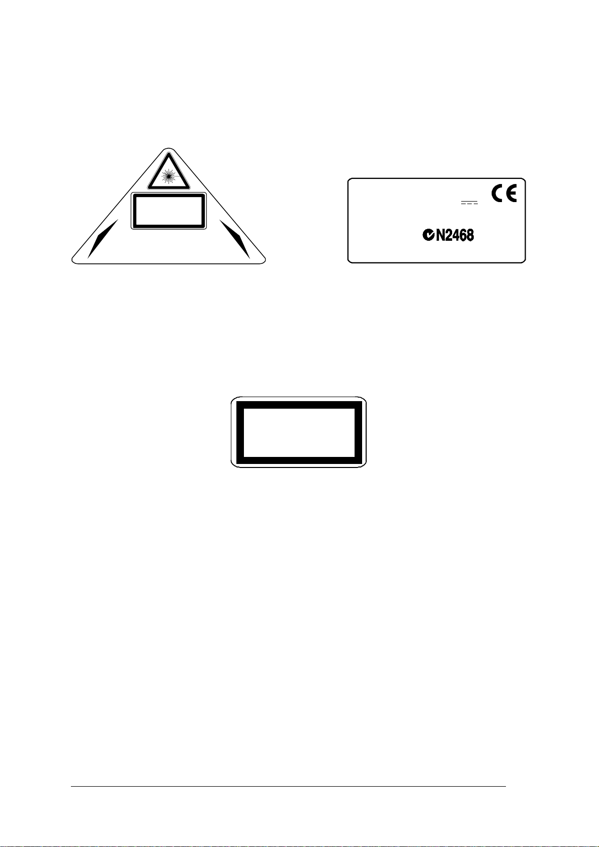
Warning labels indicating exposure to laser light and the device classification are applied
onto the body of the scanner (Figure A, 4 and 2):
DATALOGIC S.P.A. Via Candini, 2
LASER LIGHT
DO NOT STAR E INTO BEAM
CLASS 2 LASER PRODUCT
MAXIMUM OUTPUT RADIATION 1 mW
EMITTED WAVELENGTH 630~680 nm
TO EN 60825-1:2001
AVOID EXPOSURE TO BEAM
CAUTION-CLASS 3B LASER LIGHT WHEN OPEN
LASER LIGHT EMITTED FROM THIS APERTURE
40012 Calderara di Reno - Bologna - Italy
Manufactured Volt
Model No. Amp.
Serial No.
This product conforms to the applicable requirements
of 21CFR1040 at the date of manufacture.
Warning and device class labels
Disconnect the power supply when opening the device during maintenance or installation to
avoid exposure to hazardous laser light.
The laser diodes used in this device are classified as Class 3B laser products according to EN
60825-1 regulations and as Class IIIb laser products according to CDRH regulations. As it is
not possible to apply a classification label on the laser diodes used in this device, the
following label is reproduced here:
LASER LIGHT
AVOID EXPOSURE TO BEAM
CLASS 3B LASER PRODUCT
MAXIMUM OUTP UT RADIATION 35 mW
EMITTED WAVELENGTH 630~68 0 nm
TO EN 60825-1 (2001)
Laser diode class label
Any violation of the optic parts in particular can cause radiation up to the maximum level of
the laser diode (35 mW at 630~680 nm).
POWER SUPPLY
The supply voltage for correct operation of the scanner depends on the models:
- between 20 and 30 VDC, supplied to the Lonworks Network connector, for
DX8200 Controller-X0X0 models
- between 85 and 264 VAC, supplied through the VAC power cable, for DX8200
Controller-X0X1 models.
A security system allows the laser to activate only once the motor has reached the correct
rotational speed; consequently, the laser beam is generated after a slight delay from the
power on of the scanner.
During power up of the scanner there is a current peak of about 3A caused by the motor
startup.
ix
Page 12

x
Page 13

GENERAL FEATURES
1
1 GENERAL FEATURES
1.1 INTRODUCTION
The DX8200 Controller scanner is a high performance omnidirectional barcode reader that
provides an innovative solution for omnidirectional system reading applications. In particular,
DX8200 Controller serves as both the Master of the cluster and Controller of the Lonworks
bus network where up to 13 scanners can be present to make up the reading station. The
major advantage is in eliminating the need for an external Lonworks Controller.
DX8200 Controller also interfaces directly to the Host to manage all interfacing activities:,
communications, inputs, outputs.
Another advantage of the DX8200 Controller is the built-in Ethernet connectivity which is
completely controlled by its own microprocessor and available as an alternative Host
connection to the Main and Aux port serial communication. With this connection there is no
loss in decoding performance because the TCP/IP protocol management is completely
separate from the decoding process.
The DX8200 Controller uses exclusively the PackTrack™ Operating Mode in which the
barcodes collected from the Slave scanners are assigned the correct parcel and the
message is transmitted to the Host.
However, the DX8200 Controller can also be used in Stand-Alone configurations.
The Genius™ configuration program is used to completely configure the DX8200 Controller
regarding enabled code symbologies, PackTrack™ parameters, Data formatting, etc.
Through the Controller, the relative Slave scanner configurations can also be managed.
The Controller maintains easy replacement and therefore down time reduction criteria in that
it stores the entire system configuration. If a slave scanner must be replaced, the
corresponding configuration is automatically downloaded by the Controller. If the DX8200
Controller fails, the system configuration can be restored through the Genius™ program.
The following Datalogic advanced technologies are employed in the DX8200 Controller:
ACR™
Advanced Code Reconstruction technology allows the reading of low aspect ratio labels
placed anywhere on a parcel and enhances the readability of poorly printed or damaged
codes.
CD SQUARE™
CD SQUARE™ provides useful information on label position and object shape elaborated
during the barcode reading phase. This innovative technology identifies the area in which the
code is located and measures the code distance from the scanner.
1
Page 14

1
DX8200 CONTROLLER
PACKTRACK™
PackTrack™ is a Datalogic patented parcel tracking system which improves the reading
features in omnidirectional stations. In particular, PackTrack™ manages 6-sided reading
systems when it is impossible to detect the real position of the code on the parcel, thus
overcoming the need for external accessories essential in traditional tracking systems. See
par. 4.2 for more details.
ASTRA™
Automatically Switched Reading Area™ is a Datalogic technology based on a multi-laser
architecture and a fixed mounted optic system which concentrates the multiple laser
emissions in a single laser beam. As each laser emitter is focused on a specific range of the
reading area, a sophisticated electronic controller selects the best focused laser emitter with
respect to the code to read. This allows the reading of medium-high density codes in a large
reading area on very fast conveyors.
FLEXIBILITY
The high frequency laser diode modulation system guarantees complete immunity to ambient
light and allows installation of the DX8200 Controller in any working area.
The DX8200 Controller is easily configurable by means of the Windows-based user-friendly
Genius utility program provided on CD-ROM.
Some of the main features of DX8200 Controller are listed below:
• Lonworks high speed network
• scanning speed 500 scans/sec for each scan line (1000 scans/sec. total)
• reads all popular codes
• 85-264 VAC or 24 VDC operation
• light source: solid state laser diodes; the light emitted has a wavelength in the range
630~680 nm. For laser safety precautions refer to the “Safety precautions” section at the
beginning of this manual.
2
Page 15
GENERAL FEATURES
1.1.1 Indicators
The DX8200 Controller has six LEDs on the control panel.
The indicators have the following functions:
Power ON:
(green) Indicates the scanner is ON.
1
Ext Trig:
Encoder:
Good Read:
TX Data:
(yellow) Indicates the external presence sensor is active.
available for DX8200 Controllers.
(yellow) Indicates the external encoder signal is active.
(red) Indicates a probable code is present in the reading zone.
(green) Indicates data transmission both on the main and on the auxiliary
This LED is not
interface.
Network:
(red) Indicates data transmission on the Lonworks network.
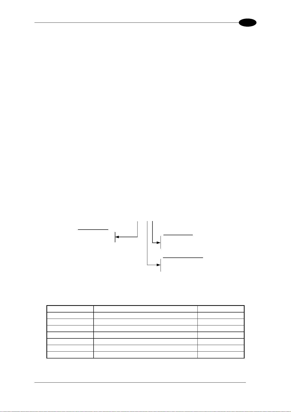
1.2 MODEL DESCRIPTION
The DX8200 Controller scanner is available in versions that differ depending on:
• number of lasers
• optical resolution
• power supply
DX8200 Controller - X 0 X X
Laser Number:
2 = Double laser
3 = Triple laser
Power supply:
0 = VDC
1 = VAC
Optical Resolution:
0 = Standard resolution
1 = High resolution
1.3 ACCESSORIES
The following DX8200 Controller accessories are available on request:
Name
CAB-8101 Cable master/slave 1 m 93A051020
CAB-8102 Cable master/slave 2 m 93A051030
CAB-8105 Cable master/slave 5 m 93A051040
CAB-8305 Cable power + termination 5 m 93A051268
INT-60 20 mA C.L. interface board 93A151021
PWR-120 Power unit 110/230 V AC - 24 V DC 93ACC1530
BTK-8000 Terminator kit (5 pcs) 93ACC1090
Description Part Number
3
Page 16

1
DX8200 CONTROLLER
1.4 APPLICATIONS
The DX8200 Controller barcode reader is specifically designed for industrial applications and
for all cases requiring high reading performance such as:
• code reconstruction
• reading of codes covered by plastic film
• reading of codes with a wide depth of field
• reading of high resolution codes positioned at long distances from the reader
• code reading on fast moving objects.
4
Page 17
INSTALLATION
2
2 INSTALLATION
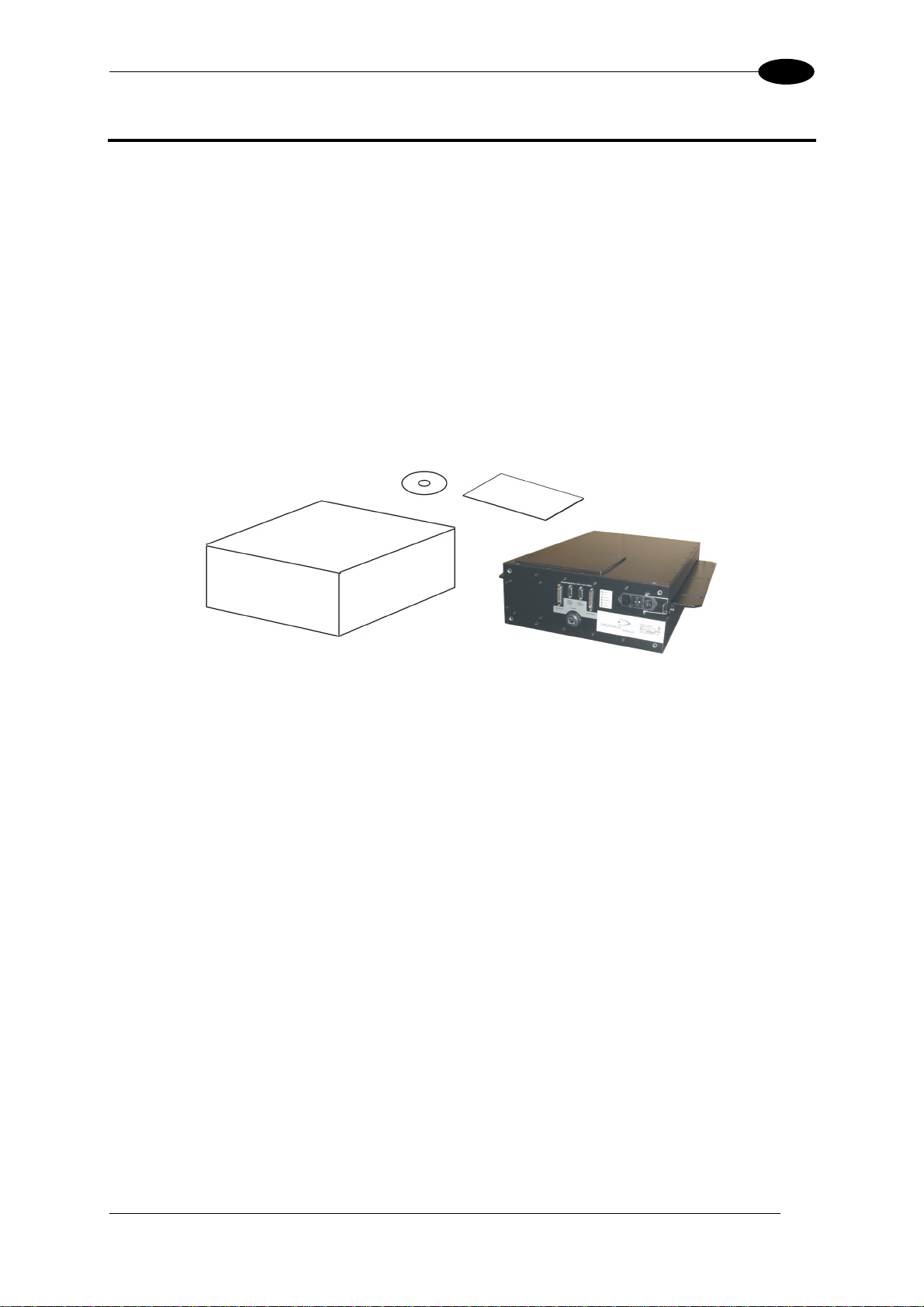
2.1 PACKAGE CONTENTS
Verify that the DX8200 Controller and all the parts supplied with the equipment are present
and intact when opening the packaging; the list of parts includes:
• DX8200 Controller
• Installation Manual + barcode test chart
• CD-ROM
Package Contents
5
Page 18

2
DX8200 CONTROLLER
2.2 MECHANICAL INSTALLATION
DX8200 Controller can be installed to operate in any position.
There are 2 mounting rails on the sides of the scanner for installation.
The diagram below gives all the information required for installation; refer to par. 4.4 for correct
positioning of the scanner with respect to the code passage zone.
40
10
1.6
0.4
0.4
576
22.7
470
18.5
170
6.7
9
170
6.7
118
4.6
53
2.1
385
64
15.16
2.5
513
20.2
mm
inch
150
5.9
94
3.7
POWER ON
EXT TRIG
ENCODER
GOOD READ
TX DATA
NETWORK
DX8200 Controller Overall Dimensions
6
Page 19

INSTALLATION
2
2.3 ELECTRICAL CONNECTIONS
The DX8200 Controller employs a Lonworks network used to build a multi-sided or extended
width omni-station system connecting several slave scanners. It interfaces with the Host
using either the serial port or Ethernet connection.
It is equipped with the following connectors:
6
5
4
Control panel
3
2
1
Host Interface connector 25-pin male
c
Reserved connector 9-pin female
d
Ethernet connector RJ45
e
RS232 debug connector – for Service only 9-pin female
f
Lonworks Network connector 17-pin female
g
VAC Power supply connector
h
2.3.1 Power Supply
The supply voltage for correct operation of the scanner depends on the models:
- between 20 and 30 VDC, supplied to the Lonworks OUTPUT connector, for DX8200
Controller-X0X0 models
- between 85 and 264 VAC, supplied through the VAC cable, for DX8200 Controller-
X0X1 models.
For VDC models, the PWR power supplies (optional), supply the power necessary for the
entire network of DX8200 Controller and relative Slaves and allows main power to be used.
For VAC models the main AC power connects directly to the DX8200 Controller to power the
entire network.
A security system allows the laser to activate only once the motor has reached the correct
rotational speed; consequently, the laser beam is generated after a slight delay from the
power on of the scanner.
During power up of the scanner there is a current peak of about 3A caused by the motor
startup.
7
Page 20

2
2.3.2 Ethernet
DX8200 Controller
1
TX+
2
TX-
3
RX+
n. c.
4
5
n. c.
6
RX-
n. c.
7
n. c.
8
n. c. = not connected
HUB / SWITCH
1
2
3
4
5
6
7
8
2.3.3 Host Interface
RJ45 Modular Connector
RJ45 Modular Connector
1
13
DX8200 CONTROLLER
14
25
25-pin male D-sub Connector
Host Interface Connector Pinout
Pin Name Function
1 Shield Internally connected by capacitor to chassis
20 RXAUX Receive data of auxiliary RS232 (referred to GND)
21 TXAUX Transmit data of auxiliary RS232 (referred to GND)
8 OUT 1+ Configurable digital output 1 – positive pin
22 OUT 1- Configurable digital output 1 – negative pin
11 OUT 2+ Configurable digital output 2 – positive pin
12 OUT 2- Configurable digital output 2 – negative pin
16 OUT 3A Configurable digital output 3 – polarity insensitive
17 OUT 3B Configurable digital output 3 – polarity insensitive
18 EXT_TRIG A External trigger (polarity insensitive)
19 EXT_TRIG B External trigger (polarity insensitive)
6 ENC A Encoder input signal (polarity insensitive)
10 ENC B Encoder input signal (polarity insensitive)
14 IN3A Input signal 3
15 IN4A Input signal 4
24 IN_REF Common reference of IN3 and IN4
9, 13 VS VDC I/O supply voltage – positive pin
23, 25 GND VDC I/O supply voltage – negative pin
Pin RS232 RS485 Full-Duplex
RS485 Half-
Duplex
20 mA C.L.
(INT-60 Only)
2 TX TX485+ RTX485+ CLOUT+
3 RX RX485+ CLIN+
4 RTS TX485- RTX485- CLOUT5 CTS RX485- CLIN7 GND_ISO GND_ISO GND_ISO GND*
* For 20 mA C.L. connections, GND is the same of the scanner power supply.
8
Page 21

INSTALLATION
2
Main Interface
The main serial interface is compatible with the following electrical standards:
RS232
RS485 full-duplex
RS485 half-duplex
20 mA current loop
The 20 mA Current Loop interface is available if the optional INT-60 accessory is installed.
This accessory interface replaces the RS232/RS485 selections.
The main serial interface type and its relative parameters (baud rate, data bits, etc.) are
selected via software using the Genius™ utility program. For more details refer to the
section "Main Serial Port" in the Genius™ Help On Line.
Details regarding the connections and use of the main interface selection are given in the
next paragraphs.
RS232 Interface
The main serial interface is used for communication with the Host computer and allows both
transmission of code data and configuring the reader.
The following pins of the 25-pin connector are used for RS232 interface connection
depending on the reader model:
Pin Name Function
2 TX Transmit
3 RX Receive
4 RTS Request to send
5 CTS Clear to send
7 GND-ISO Main signal ground
The RTS and CTS signals control data transmission and synchronize the connected devices.
If the RTS/CTS hardware protocol is enabled, the DX8200 Controller activates the RTS
output to indicate a message can be transmitted. The receiving unit must activate the CTS
input to enable the transmission.
DX8200 Controller
Shield
RS232 Connections
2
TX
3
RX
RTS4
CTS
5
7
GND-ISO
1
USER INTERFACE
RXD
TXD
GND
Earth
Ground
9
Page 22

2
DX8200 CONTROLLER
RS485 Full-Duplex Interface
The RS485 full-duplex interface is used for non-polled communication protocols in
point-to-point connections over longer distances than those acceptable for RS232
communications or in electrically noisy environments.
The following pins of the 25-pin connector are used for RS485 full-duplex interface
connection:
Pin Name Function
2 TX485 + RS485 output (+)
3 RX485 + RS485 input (+)
4 TX485 - RS485 output (-)
5 RX485 - RS485 input (-)
7 GND-ISO Main signal ground
DX8200 Controller
USER INTERFACE
2
TX485+
3
RX485+
4
TX485-
RX485-
5
RX485+
TX485+
RX485-
TX485-
7
GND_ISO
1
Shield
GND
Earth
Ground
RS485 Full-Duplex Interface Connections
RS485 Half-Duplex Interface
The RS485 half-duplex interface can be used for multidrop connections with a Datalogic
multiplexer or it can also be used for a master/slave layout.
The following pins of the 25-pin connector are used for RS485 half-duplex interface
connection:
Pin Name Function
2 RTX485 + RS485 input/output (+)
4 RTX485 - RS485 input/output (-)
7 GND-ISO Main signal ground
DX8200 Controller
MULTIPLEXER
10
2
Shield
RTX485+
4
RTX485-
7
GND_ISO
1
RTX485+
RTX485-
RS485REF
Earth
Ground
RS485 Half-Duplex Interface Connections
Page 23

INSTALLATION
r
2
20 mA Current Loop (INT-60 Accessory Only)
When the INT-60 accessory board is installed, the DX8200 Controller is equipped with a 20
mA current loop interface. The INT-60 board supports both active and passive type
connections.
Active Connections
The following pins of the 25-pin output connector are used for the active connections:
Pin Name Function
4 CLOUT - Current Loop Output (-)
5 CLIN - Current Loop Input (-)
7 GND Earth Ground*
* For 20 mA C.L. connections, GND is the same as the scanner power supply GND.
DX8200 Controller
20 mA
5
C.L. IN-
USER INTERFACE
GND
7
20 mA
C.L. OUT-
4
20 mA C.L. Active Connections
Passive Connections
The following pins of the 25-pin output connector are used for the passive connections:
Pin Name Function
2 CLOUT + Current Loop Output (+)
4 CLOUT - Current Loop Output (-)
3 CLIN + Current Loop Input (+)
5 CLIN - Current Loop Input (-)
DX8200 Controlle
3
5
C.L. IN+
C.L. IN-
USER INTERFACE
+
2
C.L. OUT+
4
C.L. OUT-
MAX. 300 METERS
+
20 mA C.L. Passive Connections
11
Page 24

2
X
X
5
DX8200 CONTROLLER
Auxiliary Interface
The auxiliary serial interface is equipped with RS232 full-duplex interface connections. The
interface type is exclusive and is selectable through the Genius™ configuration program.
The following pins of the 25-pin connector are used for RS232 full-duplex interface
connection:
Pin Name Function
20 RXAUX Receive data
21 TXAUX Transmit data
23 SGND AUX Auxiliary signal ground
DX8200 Controller
Shield
USER INTERFACE
20
RXAUX
21
TXAU
23
GNDAU
1
TXD
RXD
GND
Earth
Ground
2.3.4 Lonworks
Pin Name Function
A1 GND supply voltage (negative pin)
A2 VS supply voltage 20 to 30 Vdc (positive pin)
1 Shield A
3 Shield B
8 Lon A+ lonworks A line (positive pin)
9 Lon A- lonworks A line (negative pin)
10 Lon B+ lonworks B line (positive pin)
11 Lon B- lonworks B line (negative pin)
13 SYS_ENC Rigenerated encoder output
15 Refer Reference voltage of I/O circuit
RS232 Auxiliary Interface Connections
1
scanner side
external vi ew
1
A1
OUTPUT
Lonworks OUTPUT pinout
A2
12
Page 25

INSTALLATION
A
A
V
2
2.3.5 RS232 Debug
The use of this connector is reserved for Service:
5
RS232 debug connector
1
69
RS232 Debug connector pinout
Pin Name Function
2 TXD Transmitted data
3 RXD Received data
5 GND Ground
2.3.6 Inputs
ENC is the encoder input and detects the conveyor speed.
EXT_TRIG is the presence sensor that, when active, tells the scanner that a pack is entering
the reading area.
All inputs are optocoupled and driven by a constant current generator; the command signal is
filtered through an anti-disturbance circuit which generates a configurable delay of about 5
ms or 500 µs.
The electrical features of the inputs are:
Maximum voltage 30 V
Maximum current 10 mA
DX8200 Controller
+ 5V
DX8200 Controller
+ 5V
Input NPN
Polarity Insensitive Common Reference
EXTERNAL TRIGGER/
9
VS
~
-
+
~
B
GND
Vext
ENCODER
V
Ground
DX8200 Controller
+ 5V
~
+
~
9
INREF
-
IN3A
EXTERNAL TRIGGER/
9
VS
B
~
-
+
~
GND
Vext
ENCODER
V
Ground
+ 5V
~
-
+
~
IN4A
EXTERNAL DEVICE
ext
VS
V
GND
Vext
EXTERNAL DEVICE
V
GND
13
Page 26

2
A
A
r
Input PNP Connections
Polarity Insensitive Common Reference
DX8200 Controller
+ 5V
~
-
+
~
B
GND
EXTERNAL TRIGGER/
Vext
ENCODER
V
DX8200 Controller
+ 5V
DX8200 Controller
+ 5V
~
-
+
~
B
GND
EXTERNAL TRIGGER/
Vext
ENCODER
V
+ 5V
2.3.7 Outputs
The electrical features of the outputs are given below:
Output Open Collector Connections
Polarity Insensitive Polarity Sensitive
DX8200 Controller
USER INTERFACE
100 Vdc max
Vext
DX8200 Controlle
DX8200 CONTROLLER
Vext
EXTERNAL DEVICE
V
IN3A
~
-
+
~
IN4A
~
-
+
~
INREF
GND
Vext
V
GND
USER INTERFACE
Vext 30 Vdc max
A
B
The OUT3 electrical features are given below:
Collector-Emitter voltage ± 100 V max.
Collector current.: 240 mA pulse max
160 mA continuous max
R on 6 – 15 Ω
R off > 500 Ω
Off-state leakage current < 1 µA
Maximum power dissipation 550 mW at 50°C
(Ambient temperature).
+
-
The OUT1 / OUT2 electrical features are given
below:
Collector-Emitter voltage 30 V max.
Collector current.: 130 mA pulse max.
40 mA continuous max.
Saturation voltage (VCE) 1 V at 10 mA max.
Maximum power dissipation 90 mW at 50°C
(Ambient temperature).
14
Page 27

INSTALLATION
2
2.4 LAYOUTS
DX8200 Controller Master interprets data from each scanner and performs the correct
barcode assignment to the parcel using the PackTrack™
External devices such as a presence sensor and an encoder are all connected to the
DX8200 Controller, which is also connected to a Host PC.
A single DX8200 Controller provides a Lonworks communication line having up to 5
scanners. The last scanner requires the termination connector BTK-8000. The maximum
allowable length for the entire bus cabling is 65 m.
The following figures show 2 possible layouts for the DX8200 Controller.
Bus Interface SLAVE Scanners
1 ...
DX8200 Controller MASTER Scanner
(VAC model)
operating mode.
*
85-260 VAC
HOST
85-260 VAC85-260 VAC
PRESENCE
SENSOR**
BTK-8000
DATALOGIC CAB-810X CABLES
ENCODER
PWR-120/240/480
Bus Interface SLAVE Scanners
1
2
DX8200 Controller MASTER Scanner
(VDC model)
3
…
HOST
PRESENCE
SENSOR**
CAB-8305
DATALOGIC CAB-810X CABLES
ENCODER
** Presence Sensor connected to External Trigger Input
*
The maximum number of scanners on the Lonworks cluster is 6 (1 DX8200 controller + 5 slaves). Positive environmental
conditions (i.e reduced number of barcodes, conveyor speed, reading area dimensions…) to be evaluated case by case, may
further increase the number of slaves up to the theoretical limit of 13.
15
Page 28

3
DX8200 CONTROLLER
3 SOFTWARE CONFIGURATION
3.1 GENIUS™ INSTALLATION
Genius
advantages:
• Multi-language version;
• Defined configuration directly stored in the reader;
• Communication protocol independent from the physical interface allowing to consider the
To install Genius™, proceed as follows:
1) Turn on the PC that will be used for configuration and launch Windows 95/98 or NT;
2) Insert the Genius™ CD-ROM;
3) Wait for the CD autorunning and follow the installation procedure.
3.2 GUIDE TO CONFIGURATION
After installing the Genius™ software program (see par. 3.1) the following window appears
asking the user to choose the desired configuration level:
™
is a new Datalogic scanner configuration tool providing several important
reader as a remote object to be configured and monitored.
Genius™ Wizard Opening Window
For the DX8200 Controller the Wizard is not available and if selected a warning message
appears indicating that Advanced Mode will be used.
16
Page 29

SOFTWARE CONFIGURATION
3
3.3 ADVANCED GENIUS™ CONFIGURATION
The ADVANCED selection available when starting the Genius™ program is addressed to
expert users being able to complete a detailed scanner configuration. By choosing this option
it is possible either to start a new scanner configuration or to open and modify an old one.
The desired parameters can be defined in the following window, similar to the MS Explorer:
Genius™ Parameter Explorer Window
The procedure for setting the scanner parameters is supported by a help on-line, which is
displayed in an HTML browser.
It can be selected from the Configuration Help option available in the Help menu. In addition,
a context-sensitive help can be enabled by pressing the <F1> key after selecting the desired
parameter.
17
Page 30

3
DX8200 CONTROLLER
3.4 PARAMETER DEFAULT VALUES
The following table contains the list of the factory default settings for the DX8200 Controller.
Genius™ also allows checking the parameter default values by selecting the "Compare
parameters" option available in the Tools menu and comparing the current scanner
configuration to the default one.
Parameter Default Setting
Code Definition
Code Combination Single Label
No read Message
No Read String <CAN>
Code Label Settings #1
Code Symbology Interleaved 2 of 5
Label Length 8
Min Code Position 0
Max Code Position 255
Check Digit Disabled (unchecked)
Pattern Match String Empty
Code Label Settings #2
Code Symbology Code 39
Label Length Variable
Minimum Label Length 1
Maximum Label Length 48
Min Code Position 0
Max Code Position 255
Check Digit Disabled (unchecked)
Pattern Match String Empty
Operating Modes
Operating Mode Selection PackTrack
Physical Encoder Enabled (checked)
Encoder Step (hundredths of mm) 100
PS Line (mm) 0
Presence Sensor Input 1
Presence Sensor Input Level Active Closed
Distance from PS Line to Tx Line (mm) 1500
Transmission Edge Trailing
Max Number of Packs 10
Minimum Distance Error Behaviour Compose
Minimum Distance Between Packs (mm) 30
Minimum Pack Length Error Behaviour Discard Item
Minimum Pack Length (mm) 50
Window Dimension (mm) 15
Statistics Disabled (unchecked)
Reading System Layout
Number of Scanners 1
Modify Scanner Configuration Disabled (unchecked)
Global No Read Message
18
Page 31

SOFTWARE CONFIGURATION
3
Parameter
Data Communication Settings
Default Setting
Host Application Protocol Type Standard
Data Format
Termination After No Read Message Enabled
Parameters
Header String <STX>
Code Identifier Disabled
Termination String <CR><LF>
Data Packet Separators <CR><LF>
Code Field Length Setting Variable Length
Main Serial Port
Data Tx Enabled (checked)
Parameters
Main Port Communication Mode Standard
Main Port Electrical Interface RS232
Handshake None
Baud Rate 9600
Parity None
Data Bits 8
Stop Bits 1
Auxiliary Serial Port
Data Tx Enabled (checked)
Pass Through Disabled (unchecked)
Parameters
Baud Rate 115200
Parity None
Data Bits 8
Stop Bits 1
Digital I/O Setting
Digital Input Lines Setting
Debouncing For Input 1, 3 and 4 5ms
Debouncing For Input 2 500 µs
Input 1 Active Level Overridden by Op. Mode Active Closed
Input 2 Active Level Overridden by Op. Mode Active Closed
Input 3 Active Level Overridden by Op. Mode Active Closed
Input 4 Active Level Overridden by Op. Mode Active Closed
19
Page 32

3
DX8200 CONTROLLER
Parameter
Default Setting
Output 1
Line State Normally Open
Activation Event Complete Read
Alternative Activation Event Multiple Read
Deactivation Event Timeout
Alternative Deactivation Event None
Deactivation Timeout (ms) 50
Output 2
Line State Normally Open
Activation Event No Read
Alternative Activation Event Partial Read
Deactivation Event Timeout
Alternative Deactivation Event None
Deactivation Timeout (ms) 50
Output 3
Line State Normally Open
Activation Event None
Alternative Activation Event None
Deactivation Event None
Alternative Deactivation Event None
20
Page 33

READING FEATURES
4
4 READING FEATURES
4.1 ADVANCED CODE RECONSTRUCTION
The traditional way of barcode reading could be called "Linear Reading". In this case, the
laser beam crosses the barcode symbol from its beginning to its end as shown in the figure
below.
Laser Beam
Linear reading
In "Advanced Code Reconstruction" mode it is no longer necessary for the laser beam to
cross the label from the start to the end. With just a set of partial scans on the label (obtained
using the motion of the label itself), the DX8200 Controller is able to "reconstruct" the
barcode. A typical set of partial scans is shown below.
Code Direction
Partial scans
None of the partial scans contains the whole label. The decoder aligns each partial scan
correctly and combines them in order to obtain the entire code.
The alignment is performed by calculating the time difference from one partial scan to
another using a reference code element.
21
Page 34

4
DX8200 CONTROLLER
4.2 PACKTRACK™
PackTrack™ is a patented operating mode for DATALOGIC Omnidirectional Reading
Stations used to read and correctly assign codes read on parcels when placed in the scanner
Reading Area at the same time.
In fact, in the example below, the codes of two or more consecutive parcels are found at the
same time in the scanner reading area. Therefore the condition occurs where, in the
sequence of the two parcels, the code of the second parcel is read first, just before the code
of the previous parcel. A system without PackTrack™ would assign the code of the second
parcel to the first parcel and viceversa, thus causing a gross error in the sortation.
Conveyor
direction
End of the
PS Photocell or
equivalent signal
Conveyor
direction
Reading Area
PS
line
PackTrack™ Conditions
Tracking Area
Tracking Area
TX
line
22
Page 35

READING FEATURES
4
4.3 PERFORMANCE
The scan rate is 500 scans/sec for each scan line (1000 total).
Refer to the diagrams in par. 4.4 for further details on the reading features.
These diagrams are taken on various resolution sample codes at a 25 °C ambient
temperature depending on the conditions listed under each diagram.
4.3.1 Reading Conditions
• ANSI Grade B minimum
The following tables describe the requirements for standard applications. Please contact
Datalogic for specific advice on maximizing the reading performance possibilities to obtain
the best possible performance for your application.
Minimum Code Height for Omnidirectional Reading (mm)
Conveyor Speed (m/s) 0.5 1 1.5 2 2.5 3
2/5 Interleaved
Code Resolution
(mm)
0.25
0.30
0.33
0.38
0.50
0.60
1.00
10 12 14 17 19 21
12 14 16 18 20 22
13 14 17 19 21 23
14 16 18 20 22 24
18 19 21 23 25 27
21 22 24 26 28 30
34 35 36 37 39 41
Table 1
Minimum Code Height for Omnidirectional Reading (mm)
Conveyor Speed (m/s) 0.5 1 1.5 2 2.5 3
Code 39
Code Resolution
(mm)
0.25
0.30
0.33
0.38
0.50
0.60
1.00
9 10 12 15 17 19
10 11 13 16 18 20
11 12 14 16 18 20
12 13 15 17 19 21
15 16 17 19 21 24
18 19 20 21 23 26
28 29 30 31 32 34
Table 2
Minimum Code Height for Omnidirectional Reading (mm)
Conveyor Speed (m/s) 0.5 1 1.5 2 2.5 3
Code 128 – Ean 128
Code Resolution
(mm)
0.25
0.30
0.33
0.38
0.50
0.60
1.00
7 9 12 14 16 18
8 10 12 15 17 19
9 11 13 15 17 19
10 12 14 16 18 20
12 13 16 18 20 22
14 15 17 19 21 24
22 23 24 26 28 30
Table 3
23
Page 36

4
DX8200 CONTROLLER
Minimum Code Height for Omnidirectional Reading (mm)
Conveyor Speed (m/s) 0.5 1 1.5 2 2.5 3
Codabar
Code Resolution
(mm)
0.25
0.30
0.33
0.38
0.50
0.60
1.00
12 14 16 18 20 22
13 15 17 20 22 24
14 16 18 20 23 25
16 18 20 22 24 26
20 22 24 26 28 30
23 25 27 29 31 34
36 38 40 42 44 47
Table 4
Minimum Code Height for Omnidirectional Reading (mm)
Conveyor Speed (m/s) 0.5 1 1.5 2 2.5 3
EAN 8-13, UPC-A
Code Resolution
(mm)
0.25
0.30
0.33
0.38
0.50
0.60
1.00
8 9 11 13 15 17
9 10 11 14 16 18
9 10 12 14 16 18
11 12 13 15 17 19
13 14 15 16 18 20
15 16 17 18 19 22
24 25 26 27 28 29
Table 5
24
Page 37

READING FEATURES
4.4 READING DIAGRAMS
Single Configuration DX8200 Controller 201X
4
0.25 mm codes
DOF
400
FW
500
Reading Area
120
Ref.
1100
Dimensions given in mm
CONVEYOR PLANE
Reading diagram for double-diode high resolution model
25
Page 38

4
DX8200 CONTROLLER
Single Configuration DX8200 Controller 200X
0.30 mm codes
Ref.
DOF
Dimensions given in mm
1300
20
CONVEYOR PLANE
600
500
FW
700
600
Reading Area
Reading diagram for double-diode standard resolution model
26
Page 39

READING FEATURES
Single Configuration DX8200 Controller 200X
4
0.50 mm codes
Ref.
Dimensions given in mm
1500
FW
800
600
DOF
900
700
Reading Area
20
CONVEYOR PLANE
Reading diagram for double-diode standard resolution model
27
Page 40

4
DX8200 CONTROLLER
Single Configuration DX8200 Controller 301X
0.25 mm codes
Ref.
DOF
Dimensions given in mm
1100
FW
500
600
Reading diagram for triple-diode high resolution model
Reading Area
120
CONVEYOR PLANE
28
Page 41

READING FEATURES
Single Configuration DX8200 Controller 300X
4
0.30 mm codes
Ref.
DOF
800
600
FW
700
500
Reading Area
Dimensions given in mm
1400
20
100
CONVEYOR PLANE
Reading diagram for triple-diode standard resolution model
29
Page 42

4
DX8200 CONTROLLER
Single Configuration DX8200 Controller 300X
0.50 mm codes
Ref.
DOF
1000
700
300
Dimensions given in mm
1500
100
FW
900
500
Reading Area
CONVEYOR PLAN E
Reading diagram for triple-diode standard resolution model
30
Page 43

READING FEATURES
Side-by-Side Configuration DX8200 Controller 201X
4
0.25 mm codes
1140
Ref.
Dimensions given in mm
1100
FW
DOF
400
900
Reading Ar ea
Reading diagram for side-by-side double-diode high resolution model
120
CONVEYOR PLANE
Side-by-side configurations ar e shown with the minimum overlap. You should adapt
the distance between the scanners and therefore the field width according to your
application.
31
Page 44

4
DX8200 CONTROLLER
Side-by-Side Configuration DX8200 Controller 200X
0.30 mm codes
1240
Ref.
DOF
600
FW
1200
Reading Area
Dimensions given in mm
1300
20
CONVEYOR PLANE
Reading diagram for side-by-side double-diode standard resolution model
Side-by-side configurations ar e shown with the minimum overlap. You should adapt
the distance between the scanners and therefore the field width according to your
application.
32
Page 45

READING FEATURES
Side-by-Side Configuration DX8200 Controller 200X
0.50 mm codes
1240
Ref.
4
DOF
900
700
FW
1200
1000
Reading Area
Dimensions given in mm
1500
20
100
CONVEYOR PLANE
Reading diagram for side-by-side double-diode standard resolution model
Side-by-side configurations ar e shown with the minimum overlap. You should adapt
the distance between the scanners and therefore the field width according to your
application.
33
Page 46

4
DX8200 CONTROLLER
Side-by-Side Configuration DX8200 Controller 301X
0.25 mm codes
1140
Ref.
DOF
600
FW
900
Reading Area
Dimensions given in mm
1100
120
CONVEYOR PLANE
Reading diagram for side-by-side triple-diode high resolution model
Side-by-side configurations ar e shown with the minimum overlap. You should adapt
the distance between the scanners and therefore the field width according to your
application.
34
Page 47

READING FEATURES
Side-by-Side Configuration DX8200 Controller 300X
0.30 mm codes
1240
Ref.
4
DOF
800
600
FW
1200
1000
Reading Area
Dimensions given in mm
1400
20
100
CONVEYOR PLANE
Reading diagram for side-by-side triple-diode standard resolution model
Side-by-side configurations ar e shown with the minimum overlap. You should adapt
the distance between the scanners and therefore the field width according to your
application.
35
Page 48

4
DX8200 CONTROLLER
Side-by-Side Configuration DX8200 Controller 300X
0.50 mm codes
1040
Ref.
DOF
1000
700
FW
1200
1000
Reading Area
Dimensions given in mm
100
1500
CONVEYOR PLANE
Reading diagram for side-by-side triple-diode standard resolution model
Side-by-side configurations ar e shown with the minimum overlap. You should adapt
the distance between the scanners and therefore the field width according to your
application.
36
Page 49

MAINTENANCE
5
5 MAINTENANCE
5.1 CLEANING
Clean the laser beam output windows periodically for correct operation of the reader.
Dust, dirt, etc. on the window may alter the reading performance.
Repeat the operation frequently in particularly dirty environments.
Use soft material and alcohol to clean the windows and avoid any abrasive substances.
Clean the windows of the DX8200 Controller when the scanner is t urned
off or at least when the laser beam is not active.
WARNING
5.2 AUTOMATIC SCANNER REPLACEMENT
Principally used for PackTrack configurations, the
functioning automatically after one or more Slave scanners are replaced in a Master/Slave
Lonworks network.
1.
When the Modify Scanner Configuration parameter in Genius™ i s checked, you
can configure the Lonworks Slave Scanner Common Parameters (Code and
Reconstruction Parameters), through the Master. By configuring the Slave scanners
through the Master, the Automatic Scanner Replacement procedure (ASR) is
implemented.
2. After system configuration through the Master,
Environmental parameters to the Master EEPROM. The Master will force the
Slaves Operating Mode and Code Reading Symbologies and store all the Slave
PackTrack calibration tables.
ASR procedure allows restoring system
Send the configuration with
By Saving thi s configuration to file (.ddc), the Master scanner can be
replaced if necessary. To replace the Master, first load the saved
NOTE
configuration from file to the new Master. Then replace the Master.
Slave Scanner Replacement
A. Power down the entire system.
B. Replace the Slave scanner with a new one (default settings).
C. Power up the system and wait for initialization.
37
Page 50

5
DX8200 CONTROLLER
ASR works only if the Slave devices have software 1.30 and later for 6000
NOTE
Family scanners.
5.3 REPLACING THE PROTECTION FUSES (FOR AC MODELS)
The device must be opened by qualified personnel only.
WARNING
Before removing the fuses from DX8200 Contr oller, make sure t he power
supply cable is disconnected to avoid shock or harm to the operator.
WARNING
Two protection fuses are located next to the on/off switch (Figure B, 12).
To replace them, turn the device off and disconnect the power supply cable; then, with a
screwdriver remove the fuses and replace them with new ones of the correct value (see the
following fuse selection table).
Connect the power supply cable and turn the device on again to verify the success of the
operation.
Version Fuse Type
85 - 264 Vac 3.15 A F
38
Page 51

TECHNICAL FEATURES
6
6 TECHNICAL FEATURES
DX8200 Controller
ELECTRICAL FEATURES (see note 1)
Models X0X1 Models X0X0
Input voltage 85-264 VAC 20 to 30 VDC
Current consumption (max.) 0.4 ~ 0.2 A 1.5 ~ 1.0 A
Communication interf aces
Lonworks network 1,25 Mb/s
Main RS232, RS485 full-duplex,
20 mA C.L. (INT-60) 19200
Auxiliary RS232 1200-115200
Inputs
(optocoupled, NPN or PNP)
Outputs
(optocoupled, open emitter
collector)
RS485 half-duplex,
1 external trigger, 3 auxiliary digital inputs.
3 software programmable digital ouputs.
OPTICAL FEATURES (see note 1)
Light source up to 3 semiconductor laser diodes
Wavelength 630 to 680 nm
Safety class Class 2 - EN 60825-1; Class II - CDRH
Light receiver Avalanche photodiode
Baud rate
1200-115200
READING FEATURES
Scan rate 500 scans/s for each scan line (1000 total)
USER INTERFACE
LED indicators Power ON, Ext Trig, Encoder, Good Read, TX Data,
Network
39
Page 52

6
DX8200 Controller
SOFTWARE FEATURES
READABLE CODE SYMBOLOGIES
Interleaved 2/5 Code 128/EAN 128
Code 39 standard EAN/UPC
Codabar Code 93 (standard & Full ASCII)
Code Selection
Headers and Terminators
Up to 10 code symbologies during one reading phase
Transmitted messages can be personalized using up to 128
headers and 128 terminators
Operating Modes
Configuration Modes
PackTrack™
Genius™ utility program
DX8200 CONTROLLER
Parameter Storage
Non-volatile internal FLASH
ENVIRONMENTAL FEATURES
Operating temperature 0° to +50 °C (+32° to +122 °F)
Storage temperature -20° to +70 °C (-4° to +158 °F)
Humidity 90% non condensing
Vibration resistance EN 60068-2-6 test FC
1.5 mm @ 5 to 9.1 Hz; 0.5 G @ 9.1 to 150 Hz;
2 hours on each axis
Shock resistance EN 60068-2-27 test EA
15 G; 11 ms;
3 shocks on each axis in each direction
Protection class IP54
PHYSICAL FEATURES
Mechanical dimensions 576 x 513 x 150 mm (22.7 x 20.2 x 5.9 in)
Weight about 22 Kg (48.5 lbs.)
Note 1: The features given are typical at 25 °C ambient temperature (if not otherwise
indicated).
40
Page 53

GLOSSARY
ACR™
Advanced Code Reconstruction technology allows the reading of low aspect ratio labels
placed anywhere on a parcel and enhances the readability of poorly printed or damaged
codes.
Aperture
Term used on the required CDRH warning labels to describe the laser exit window.
ASTRA™
Automatically Switched Reading Area™ is a Datalogic technology based on a multi-laser
architecture and a fixed mounted optic system which concentrates the multiple laser
emissions in a single laser beam. As each laser emitter is focused on a specific range of the
reading area, a sophisticated electronic controller selects the best focused laser emitter with
respect to the code to read. This allows the reading of medium-high density codes in a large
reading area on very fast conveyors.
Barcode
A pattern of variable-width bars and spaces which represents numeric or alphanumeric data
in machine-readable form. The general format of a barcode symbol consists of a leading
margin, start character, data or message character, check character (if any), stop character,
and trailing margin. Within this framework, each recognizable symbology uses its own unique
format.
Barcode Label
A label that carries a barcode and can be affixed to an article.
Baud Rate
A unit used to measure communications speed or data transfer rate.
CD SQUARE™
CD SQUARE™ provides useful information on label position and object shape elaborated
during the barcode reading phase. This innovative technology identifies the area in which the
code is located and measures the code distance from the scanner.
CDRH (Center for Devices and Radiol ogical Health)
This organization (a service of the Food and Drug Administration) is responsible for the
safety regulations governing acceptable limitations on electronic radiation from laser devices.
Datalogic devices are in compliance with the CDRH regulations.
EEPROM
Electrically Erasable Programmable Read-Only Memory. An on-board non-volatile memory
chip.
Full Duplex
Simultaneous, two-way, independent transmission in both directions.
Half Duplex
Transmission in either direction, but not simultaneously.
41
Page 54

Host
A computer that serves other terminals in a network, providing services such as network
control, database access, special programs, supervisory programs, or programming
languages.
Interface
A shared boundary defined by common physical interconnection characteristics, signal
characteristics and meanings of interchanged signals.
LED (Light Emitt ing Diode)
A low power electronic device that can serve as a visible or near infrared light source when
voltage is applied continuously or in pulses. It is commonly used as an indicator light and
uses less power than an incandescent light bulb but more than a Liquid Crystal Display
(LCD). LEDs have extremely long lifetimes when properly operated.
Multidrop Line
A single communications circuit that interconnects many stations, each of which contains
terminal devices. See RS485.
PackTrack™
PackTrack™ is a Datalogic patented parcel tracking system which improves the reading
features in omnidirectional stations. In particular, PackTrack™ manages 6-sided reading
systems when it is impossible to detect the real position of the code on the parcel, thus
overcoming the need for external accessories essential in traditional tracking systems. See
par. 4.2 for more details.
Parameter
A value that you specify to a program. Typically parameters are set to configure a device to
have particular operating characteristics.
Position
The position of a scanner or light source in relation to the target of a receiving element.
Protocol
A formal set of conventions governing the formatting and relative timing of message
exchange between two communicating systems.
Resolution
The narrowest element dimension which can be distinguished by a particular reading device
or printed with a particular device or method.
RS232
Interface between data terminal equipment and data communication equipment employing
serial binary data interchange.
RS485
Interface that specifies the electrical characteristics of generators and receivers for use in
balanced digital multipoint systems such as on a Multidrop line.
Scanner
A device that examines a printed pattern (barcode) and either passes the uninterpreted data
to a decoder or decodes the data and passes it onto the Host system.
42
Page 55

Serial Port
An I/O port used to connect a scanner to your computer, identifiable by a 9-pin or 25-pin
connector.
Signal
An impulse or fluctuating electrical quantity (i.e.: a voltage or current) the variations of which
represent changes in information.
Symbol
A combination of characters including start/stop and checksum characters, as required, that
form a complete scannable barcode.
Trigger Signal
A signal, typically provided by a photoelectric sensor or proximity switch, which informs the
scanner of the presence of an object within its reading zone.
UPC
Acronym for Universal Product Code. The standard barcode type for retail food packaging in
the United States.
Visible Laser Diode
A light source used in scanners to illuminate the barcode symbol. Generates visible red light
at wavelengths between 630 and 680 nm.
43
Page 56

INDEX
A
Accessories; 3
Advanced Code Reconstruction; 21
E
Electrical Connections; 7
Host Interface; 8
Power Supply; 7
F
Fuse Replacement; 38
G
General View; vi
Genius™
Advanced Configuration; 17
Guide to Configuration; 16
Installation; 16
Glossary; 41
Guide to Installation; v
I
M
Maintenance; 37
Mechanical Dimensions; 6
Model Description; 3
O
Outputs; 14
P
Package Contents; 5
PackTrack™; 22
Parameter Explorer Window; 17
Parameter Groups
Default Values; 18
Performance; 23
R
Reading Conditions; 23
Reading Diagrams; 25
Reading Features; 21
S
Indicators; 3
Inputs; 13
Installation; 5
Interfaces
Auxiliary; 12
Ethernet; 8
Lonworks; 12
Main 20 mA Current Loop; 11
Main RS232; 9
Main RS485 Full Duplex; 10
Main RS485 Half Duplex; 10
RS232 Debug; 13
L
Layouts; 15
Safety Precautions; viii
Electrical Safety; viii
Laser Safety; viii
Power Supply; ix
Software Configuration; 16
T
Technical Features; 39
Electrical; 39
Environmental; 40
Indicators; 39
Optical; 39
Physical; 40
Reading; 39
Software; 40
44
 Loading...