

Page 1

REFERENCE MANUAL
> DS8110
Barcode Scanner
Page 2

Datalogic Automation Srl
Via Lavino, 265
40050 - Monte S. Pietro
Bologna - Italy
DS8110 Barcode Scanner Reference Manual
Ed.: 05/2015
© 2015 Datalogic Automation S.r.l. ALL RIGHTS RESERVED. Protected to the fullest extent under
U.S. and international laws. Copying, or altering of this document is prohibited without express written
consent from Datalogic Automation S.r.l.
Datalogic and the Datalogic logo are registered trademarks of Datalogic S.p.A. in many countries,
including the U.S.A. and the E.U.
PackTrack, ACR, ASTRA and X-PRESS are trademarks of Datalogic Automation S.r.l. All other brand
and product names mentioned herein are for identification purposes only and may be trademarks or
registered trademarks of their respective owners.
Datalogic shall not be liable for technical or editorial errors or omissions contained herein, nor for
incidental or consequential damages resulting from the use of this material.
21/05/15
Page 3

iii
CONTENTS
REFERENCES ........................................................................................................... vii
Reference Documentation ........................................................................................... vii
Support Through the Website ...................................................................................... vii
Patents ......................................................................................................................... vii
CONVENTIONS ........................................................................................................ viii
COMPLIANCE ........................................................................................................... viii
Electrical Safety .......................................................................................................... viii
Laser Safety ................................................................................................................ viii
Bureau of Indian Standard (BIS) .................................................................................. ix
Warning and Serial labels ............................................................................................ ix
Power Supply ................................................................................................................ x
CSA Listing ................................................................................................................... x
CE Compliance ............................................................................................................. x
FCC Compliance .......................................................................................................... x
GENERAL VIEW ......................................................................................................... xi
1 INTRODUCTION .......................................................................................................... 1
1.1 Product Description ...................................................................................................... 1
1.2 Applications .................................................................................................................. 1
1.3 Model Description ......................................................................................................... 3
1.4 DS8110 versions .......................................................................................................... 3
1.5 X-PRESS (Human Machine Interface) ......................................................................... 4
1.6 Accessories .................................................................................................................. 5
1.7 Photoelectric Sensor ..................................................................................................... 7
1.8 Encoder (Tachometer) .................................................................................................. 8
1.8.1 Encoder/Tachometer Step Settings .............................................................................. 8
1.8.2 Photocraft Encoder/Tachometer Switch Setting ........................................................... 9
1.9 CBX Industrial Connection Box .................................................................................. 10
1.10 SC5000 System Controller ......................................................................................... 11
2 MECHANICAL INSTALLATION ................................................................................ 12
2.1 Preparing for Mechanical Installation .......................................................................... 12
2.2 Unpacking Instructions ............................................................................................... 13
2.3 Installation Sequence ................................................................................................. 14
2.4 What You Need to Know About Your Application ....................................................... 15
2.5 Installation ................................................................................................................... 16
2.5.1 Dimensions and Clearances ....................................................................................... 16
2.5.2 Physical Support Requirements ................................................................................. 16
2.5.3 Vibration Limitations ................................................................................................... 16
2.5.4 General Mounting Guidelines ..................................................................................... 17
2.5.5 Mounting Structure Considerations ............................................................................ 18
2.5.6 Mounting the Scanner ................................................................................................. 19
2.5.7 Positioning the Scanners ............................................................................................ 22
3 ELECTRICAL INSTALLATION .................................................................................. 23
3.1 Preparing for Electrical Installation ............................................................................. 23
3.2 Connecting a DS8110 Scanner .................................................................................. 24
3.3 Typical Connection Block Diagrams ........................................................................... 25
3.3.1 Single DS8110 Barcode Scanner to CBX510 ............................................................. 25
3.3.2 Master/Slave Array with CBX510 ............................................................................... 26
Page 4

iv
3.3.3 DS8110 Barcode Scanners in an Array with SC5000 Master .................................... 27
3.4 General Electrical Installaion guidelines and Precautions .......................................... 28
3.5 DS8110 Connector Panels ......................................................................................... 29
3.6 Connecting a PC to the DS8110 ................................................................................. 30
3.7 Power Connector Pin-Out Table ................................................................ ................. 30
3.8 Power Connections ..................................................................................................... 31
3.9 CBX510 Connection Box ............................................................................................ 32
3.9.1 Wiring Into the CBX510 Connection Box .................................................................... 32
3.10 Photoelectric Sensor Connections to CBX510 ........................................................... 33
3.10.1 Photoelectric Sensor (NPN) ........................................................................................ 34
3.10.2 Photoelectric Sensor (PNP) ........................................................................................ 35
3.11 Tachometer Wiring to CBX510 ................................................................................... 36
3.11.1 Encoder/Tachometer Wiring for NPN Output (two models) ........................................ 36
3.11.2 Encoder/Tachometer Wiring for PNP Output (two models) ........................................ 38
3.12 Digital Output Configuration to CBX510 ..................................................................... 40
3.12.1 Unpowered Outputs .................................................................................................... 40
3.12.2 Powered Outputs ........................................................................................................ 41
3.13 Connecting to the SC5000 System Controller (optional) ............................................ 42
3.14 Check Scanner Installation ......................................................................................... 43
4 USER INTERFACE .................................................................................................... 44
4.1 Getting Started ............................................................................................................ 44
4.1.1 Prerequisites ............................................................................................................... 44
4.1.2 Starting the User Interface .......................................................................................... 45
4.2 User Interface Basics .................................................................................................. 47
4.2.1 DS8110/DX8210 User Interface Menu Tree ............................................................... 47
4.2.2 Entering Text Using the Text Entry Tool ..................................................................... 47
4.2.3 Getting Help ................................................................................................................ 48
4.3 Modify Settings ........................................................................................................... 49
4.4 Modify Settings | System Info ..................................................................................... 50
4.5 Modify Settings | Global Settings ................................................................................ 53
4.5.1 Modify Settings | Global Settings | Operating Mode ................................................... 54
4.5.2 Modify Settings | Global Settings | Barcode Settings Table ........................................ 68
4.5.3 Modify Settings | Global Settings | Barcode Configuration ......................................... 73
Strip Filter Settings ..................................................................................................... 77
Strip Filter Settings ..................................................................................................... 82
Strip Filter Settings ..................................................................................................... 96
4.5.4 Modify Settings | Global Settings | Serial Ports .......................................................... 97
4.5.5 Modify Settings | Global Settings | Ethernet ............................................................. 101
User Socket n ........................................................................................................... 105
4.5.6 Modify Settings | Global Settings | Messaging .......................................................... 109
4.5.7 Modify Settings | Global Settings | Digital I/O ........................................................... 129
4.5.8 Modify Settings | Global Settings | Diagnostics ........................................................ 132
4.5.9 Modify Settings | Global Settings | Energy Saving .................................................... 134
4.5.10 Modify Settings | Global Settings | HMI Settings (Human-Machine Interface) .......... 139
4.6 Device Settings ......................................................................................................... 141
4.6.1 Device Settings | Device Name | Device Info ........................................................... 142
4.6.2 Device Settings | Device Name | Mounting ............................................................... 144
4.6.3 Device Settings | Device Name | Options ................................................................. 146
4.7 Diagnostics ............................................................................................................... 148
4.7.1 Diagnostics | Monitor ................................................................................................ 149
4.7.2 Diagnostics | Read Test ............................................................................................ 151
4.7.3 Diagnostics | Status Viewer ...................................................................................... 152
4.8 Utilities ...................................................................................................................... 155
4.8.1 Utilities | Backup or Restore ..................................................................................... 155
Page 5

v
4.8.2 Utilities | Reboot ........................................................................................................ 157
4.8.3 Utilities | Update Firmware ........................................................................................ 158
4.8.4 Utilities | Help ............................................................................................................ 160
5 BARCODE SCANNING FEATURES ....................................................................... 161
5.1 First-time Startup ...................................................................................................... 161
5.1.1 Default Parameters ................................................................................................... 161
5.1.2 Check Operations using Test Mode ......................................................................... 161
5.2 Basic Installation Procedures with the CBX510 ........................................................ 163
5.3 Basic Installation with SC5000 Controller ................................................................. 166
5.4 LED Indicators .......................................................................................................... 170
5.5 Control Panel Buttons ............................................................................................... 171
5.5.1 X-PRESS™ Human Machine Interface .................................................................... 171
X-PRESS Functions ................................................................................................. 171
Test Mode ................................................................................................................. 173
Learn ......................................................................................................................... 173
Setup ........................................................................................................................ 173
Netconfig ................................................................................................................... 173
5.5.2 Restore Button and Other Functions ........................................................................ 174
5.6 PackTrack™ ............................................................................................................. 175
5.6.1 Using the PackTrack Wizard .................................................................................... 176
5.6.2 Top-Mounted Barcode Scanner Calibration Using PackTrack ................................. 180
5.6.3 Side-Mounted Barcode Scanner Calibration Using PackTrack ................................ 186
5.6.4 Bottom-Mounted Barcode Scanner Calibration Using PackTrack ............................ 193
5.6.5 Verifying PackTrack Calibration ................................................................................ 194
5.6.6 PackTrack Validation with DLog View ...................................................................... 195
5.7 Replacing an Installed DS8110 ................................................................................ 200
5.7.1 Replacing a Standalone Scanner Using Restore ..................................................... 200
5.7.2 Replacing a Slave Scanner in an Array/Tunnel Automatically .................................. 201
5.7.3 Replacing a Slave Scanner in an Array/Tunnel Using Restore ................................ 202
5.7.4 Replacing a Master Scanner in an Array/Tunnel Using Restore .............................. 202
5.7.5 Checking the Operation of the Replacement ............................................................ 203
5.8 Typical Layouts ......................................................................................................... 204
5.8.1 Large Synchronized Network Layout ........................................................................ 204
5.9 Advanced Code Reconstruction (ACR™) ................................................................. 208
5.9.1 Tilt Angle for Advanced Code Reconstruction .......................................................... 208
5.9.2 Minimum Code Height For Advanced Code Reconstruction .................................... 210
5.10 Reading Diagram ...................................................................................................... 212
DS8110-2100 Model 1 .............................................................................................. 213
DS8110-2200 Model 2 .............................................................................................. 217
6 MAINTENANCE ....................................................................................................... 222
6.1 Overview ................................................................................................................... 222
6.2 Maintenance Tasks ................................................................................................... 223
6.2.1 Cleaning the Exit Window ......................................................................................... 224
6.2.2 Cleaning the Photoelectric Sensor ........................................................................... 225
6.2.3 Cleaning the Tachometer ......................................................................................... 226
6.2.4 Tighten Mounting Hardware ..................................................................................... 227
6.2.5 Checking Barcode Scanning System Connections .................................................. 227
6.2.6 Verify Barcode Scanner Operation ........................................................................... 227
6.2.7 Verify Photoelectric Sensor Operation ...................................................................... 227
6.2.8 Verify Tachometer Operation .................................................................................... 228
7 TROUBLESHOOTING ............................................................................................. 229
7.1 Error Codes and Resolutions .................................................................................... 230
Page 6

vi
8 TECHNICAL FEATURES ......................................................................................... 236
8.1 Technical Specifications ........................................................................................... 236
GLOSSARY .............................................................................................................. 239
INDEX ....................................................................................................................... 242
Page 7

vii
REFERENCES
REFERENCE DOCUMENTATION
The documentation related to the DS8110 management is listed below:
CBX510 Connection Box Installation Manuals
SC5000 Controller Manuals
SUPPORT THROUGH THE WEBSITE
Datalogic provides several services as well as technical support through its website. Log on
to www.datalogic.com and click on PRODUCTS and SUPPORT & SERVICES links for
further information:
PRODUCTS – FIXED INDUSTRIAL BARCODE READERS
Select your product from the links on the Fixed Industrial Barcode Readers page. The
product page describes specific Info, Features, Applications, Models, Accessories, and
Downloads including documentation, software drivers, and utility programs.
SUPPORT & SERVICES – INDUSTRIAL AUTOMATION
Several links from the Industrial Automation list take you to additional services such as:
Service Program which contains Maintenance Agreements and Warranty Extensions;
Repair Centers; On-Line RMA Return Material Authorizations; Technical Support through
email or phone; Downloads for additional downloads.
PATENTS
See www.patents.datalogic.com for patent list.
This product is covered by one or more of the following patents:
Utility patents: EP0789315B1, EP0851376B1, EP0926615B1, EP0959426B9,
EP1217571B1, EP1363228B1, JP4033958B2, JP4376353B2, US5992740, US6177979,
US6347740, US6394352, US6443360, US6527184, US6629639, US6742710
Page 8
viii
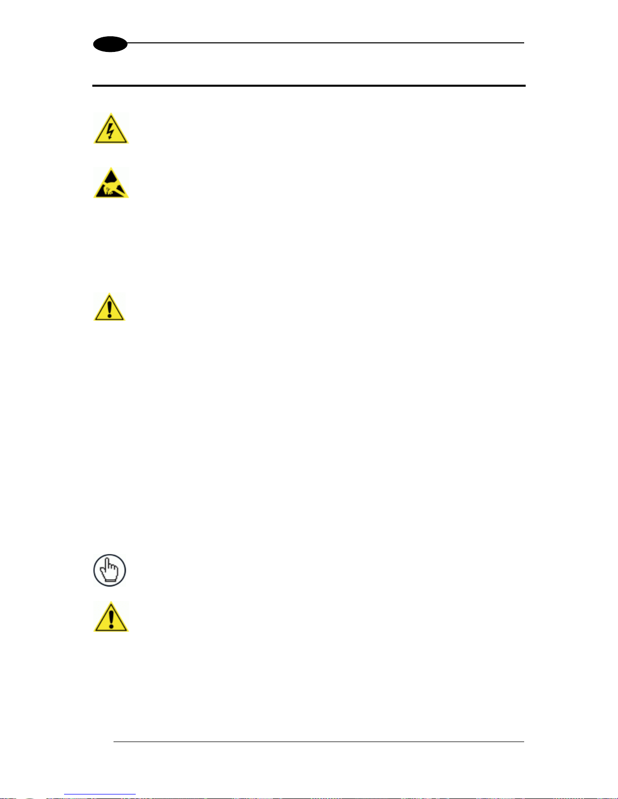
CONVENTIONS
WARNINGS OR CAUTIONS: This symbol identifies a hazard or procedure that, if
incorrectly performed, could cause personal injury or result in equipment damage. It is
also used to bring the user’s attention to details that are considered IMPORTANT.
HIGH VOLTAGE CAUTION: This symbol alerts the user they are about to perform an
action involving, either a dangerous level of voltage, or to warn against an action that
could result in damage to devices or electrical shock.
LASER CAUTION: This symbol alerts the user they are about to perform an action
involving possible exposure to laser light radiation.
ESD CAUTION: This symbol identifies a procedure that requires you take measures to
prevent Electrostatic Discharge (ESD) e.g., use an ESD wrist strap. Circuit boards are
most at risk. Please follow ESD procedures.
NOTES: This symbol draws attention to details or procedures that may be useful in
improving, maintaining, or enhancing the performance of the hardware or software being
discussed.
COMPLIANCE
ELECTRICAL SAFETY
This product conforms to the applicable requirements contained in the European Standard
for electrical safety EN 60950 at the date of manufacture.
LASER SAFETY
The following information is provided to comply with the rules imposed by international
authorities and refers to the correct use of the DS8110 barcode scanners.
Standard Regulations
These barcode scanners use low-power laser diodes. Avoid staring at the beam as one
would with any very strong light source, such as the sun.
Take care when installing the laser device to avoid inadvertent laser beam contact with the
eye of an observer, including through reflective surfaces.
This product conforms to the applicable requirements of IEC 60825-1 and complies with 21
CFR 1040.10 except for deviations pursuant to Laser Notice N° 50, date June 24, 2007. The
scanner is classified as a Class 2 laser product according to IEC 60825-1 regulations.
There is a safety device which allows the laser to be switched on only if the motor is rotating
above the threshold for its correct scanning speed.
WARNING: Use of controls or adjustments or performance of
procedures other than those specified herein may result in
exposure to hazardous visible laser light.
Page 9
ix
BUREAU OF INDIAN STANDARD (BIS)
Self Declaration – Conforming to IS 13252 (Part 1):2010, R-41009288.
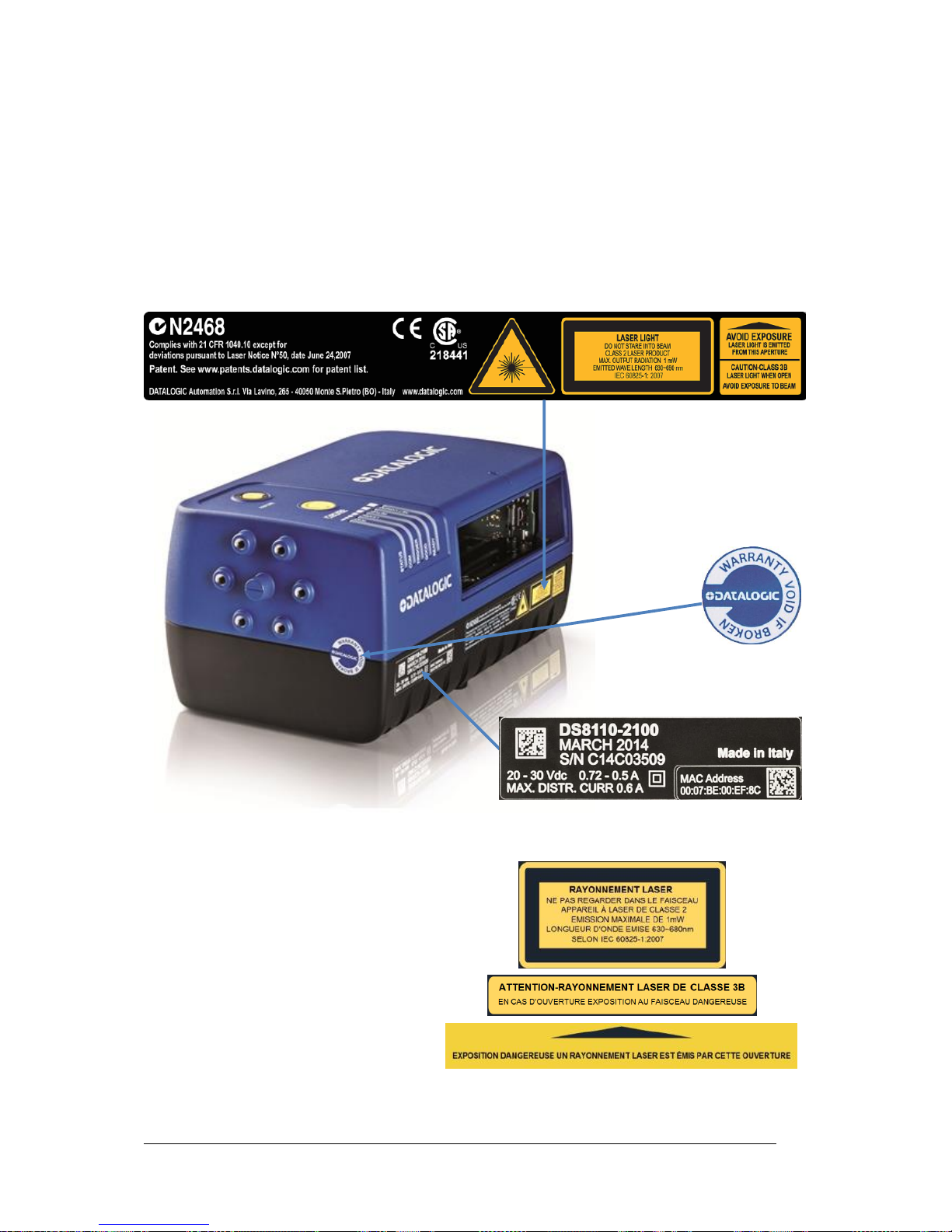
WARNING AND SERIAL LABELS
The Warning Label on the front of the barcode scanner indicates exposure to laser light and
the device classification.
Figure 1: Warning and Device Class Label Location
Produit(s) conforme selon 21CFR
1040.10 sauf des dérogations relatives
à la Laser Notice N° 50, date Juin 24,
2007.
Dans le paquet il y a l’étiquette(s) pour
les pays où le texte d'avertissement en
français sont obligatoires. Le(s) mettre
sur le produit à la place de la version
anglaise.
Figure 2: Exemple d'étiquettes d'avertissement laser
Page 10
x
WARNING: Disconnect the power supply when installing the device or during
maintenance to avoid unintentional exposure to laser light.
WARNING: There are no user serviceable parts inside the barcode scanner. Service
should only be performed by Datalogic trained and certified technicians.
Any violation of the optical parts in particular could result in exposure to Class 3B laser
light.
POWER SUPPLY
This product is intended to be installed by Qualified Personnel only.
This product is intended to be supplied by a UL listed or CSA Certified Power unit with “Class
2” or LPS power source.
CSA LISTING
Certificate: 70002952
3862 13 INFORMATION TECHNOLOGY EQUIPMENT-(CSA 60950-1-07, Second Edition)
3862 93 INFORMATION TECHNOLOGY EQUIPMENT-(UL 60950-1, Second EditionCertified to U.S. Stds)
Unattended scanning system, models DS8110-XYWZ and DX8210-XYWZ, rated 20-30 VDC
0.72-0.5 A and 20-30 VDC 1-0.7 A
CE COMPLIANCE
WARNING: This is a Class A product. In a domestic environment this
product may cause radio interference in which case the user may be
required to take adequate measures.
FCC COMPLIANCE
Modifications or changes to this equipment without the expressed written approval of
Datalogic could void the authority to use the equipment.
This device complies with PART 15 of the FCC Rules. Operation is subject to the following
two conditions: (1) This device may not cause harmful interference, and (2) this device must
Page 11
xi
accept any interference received, including interference which may cause undesired
operation.
This equipment has been tested and found to comply with the limits for a Class A digital
device, pursuant to part 15 of the FCC Rules. These limits are designed to provide
reasonable protection against harmful interference when the equipment is operated in a
commercial environment. This equipment generates, uses, and can radiate radio frequency
energy and, if not installed and used in accordance with the instruction manual, may cause
harmful interference to radio communications. Operation of this equipment in a residential
area is likely to cause harmful interference in which case the user will be required to correct
the interference at his/her own expense.
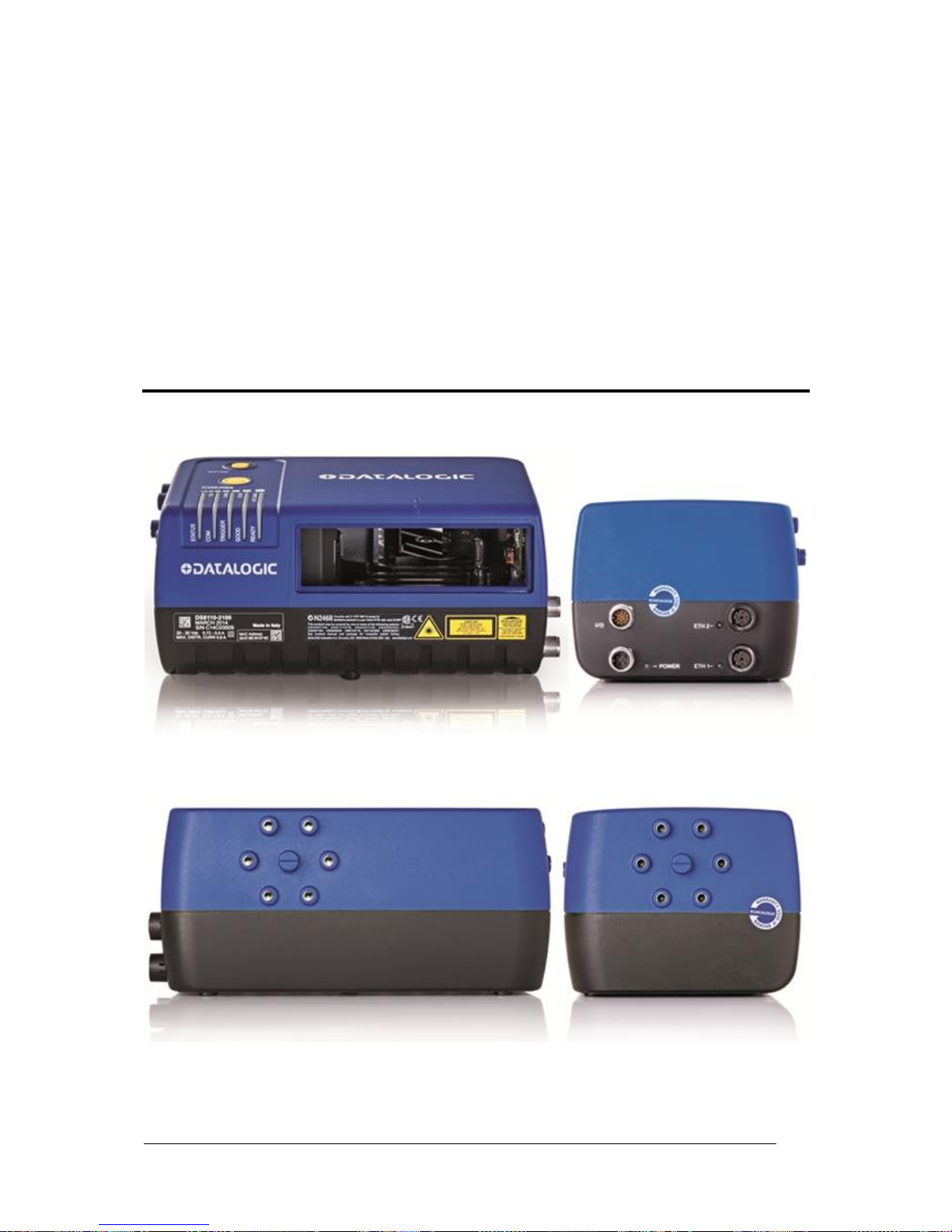
GENERAL VIEW
Figure 3: DS8110 Barcode Scanner Front and Left Side Views
Figure 4: DS8110 Barcode Scanner Back and Right Side Views
Page 12

xii
Page 13

INTRODUCTION
1
1
1 INTRODUCTION
1.1 PRODUCT DESCRIPTION
The DS8110 barcode scanner complete with decoder is designed to provide an innovative
and high performance solution in omnidirectional reading applications by combining the
following advanced technologies with Datalogic solid experience in the material handling
sector.
Some of the main features of the DS8110 are listed below:
Scanning speed 1000 scans/sec
Reads all popular codes
Supply voltage from 20 to 30 vdc
Test mode to verify the reading features and exact positioning of the scanner without the
need for external tools
Programmable in several different operating modes to suit the most various barcode
reading system requirements
Light source: solid state laser diodes; the light emitted has a wave length between
630~680 nm. For laser safety precautions refer to the “compliance” section at the
beginning of this manual
1.2 APPLICATIONS
The DS8110 barcode scanners are specifically designed for industrial applications and for all
cases requiring high reading performance such as:
Code reconstruction (ACR™)
Reading of codes covered by plastic film
Reading of codes with a wide depth of field
Reading codes within a wide field of view
Reading of high resolution codes positioned at long distances from the reader
Code reading on fast moving objects
These barcode scanners are designed for both single-reader layouts and multi-reader
layouts. For typical layouts, see section 5.8.
Page 14

DS8110 REFERENCE MANUAL
2
1
Feature
Benefit
DST
Digital Signal Technology converts analog signals to digital before
processing for much improved decoding capability especially on
poorly printed or damaged codes.
ACR™
Fifth generation Advanced Code Reconstruction technology allows
the reading of low aspect ratio labels placed anywhere on a parcel
and enhances the readability of poorly printed or damaged codes.
PACKTRACK™
Second generation Datalogic patented parcel tracking system which
improves the reading features in omnidirectional stations. In
particular, PackTrack manages 6-sided reading systems when it is
impossible to detect the real position of the code on the parcel, thus
overcoming the need for external accessories essential in traditional
tracking systems.
ASTRA™
Third generation Automatically SwiTched Reading Area is the
Datalogic technology based on a multi-laser architecture and a fixed
mounted optic system which concentrates the multiple laser
emissions in a single laser beam. As each laser emitter is focused
on a specific range of the reading area, a sophisticated electronic
controller selects the best focused laser emitter with respect to the
code to read. This allows the reading of medium-high density codes
in a large reading area on very fast conveyors.
Flexibility
The high frequency laser diode modulation system guarantees
complete immunity to ambient light and allows installation of the
DS8110 in any working area.
Reading parcels on conveyors
As a result of the ASTRA multiple laser technology, DX8210 and
DS8110 give a great real time DOF even on high speed conveyors.
Furthermore, DX8210 and DS8110 implement the PackTrack
functionality which leads to an increase of the plant production as a
result of the augmented system throughput.
EBC
Ethernet Based Connectivity is a reliable real-time network
communication between scanners in a reading station tunnel or
array.
e-Genius
e-Genius is a browser-based User Interface with the folowing
characteristics:
No software to install;
Multilanguage platform;
All the configuration parameters stored in the scanner;
Not dependent on the Physical interface; Remote access
through local network.
Energy Saving
A software parameter group which allows management of the
energy saving feature. In particular, it allows turning on/off the motor
and laser of all network scanners according to the selected digital
input, encoder, or communication channel.
The time required to restart the system is less than 1 minute
independently from the number of scanners connected.
It is suggested to use this parameter for example when the
conveyor is stopped for a lengthy period.
Page 15
INTRODUCTION
3
1
1.3 MODEL DESCRIPTION
The DS8110 barcode scanner is available in versions that differ depending on the interface
connection, the optical resolution and on the optic version:
Figure 5: Model Description Key
1.4 DS8110 VERSIONS
Model
Description
Part Number
DS8110-2100 (focus 1)
Standard
932500001
DS8110-2200 (focus 2)
High Resolution
932500002
DS8110 - X X X X
Optic Version:
0 = Linear
Optical Resolution:
1 = Standard resolution
Communication Type:
0 = Standard version
2 = High resolution
Laser Number:
2 = Double laser
Page 16
DS8110 REFERENCE MANUAL
4
1
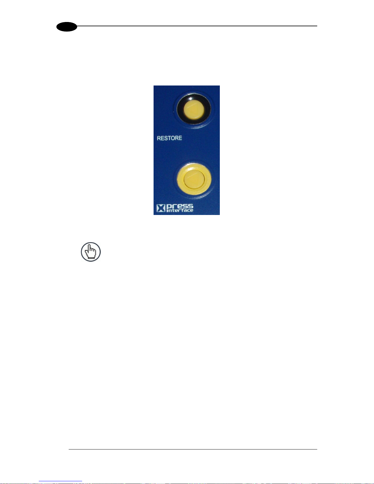
1.5 X-PRESS (HUMAN MACHINE INTERFACE)
The DS8110 barcode scanner includes two external buttons that make up the X-PRESS HMI
interface and perform specific tasks without the need of connecting to the DS8110/DX8210
User Interface. See 5.5 for functional description.
Figure 6: DS8110 X-PRESS Interface Buttons
NOTE: Some of these functions may be performed using the User
Interface. See Chapter 4.
Page 17

INTRODUCTION
5
1
1.6 ACCESSORIES
The following accessories are available on request for the DS8110 barcode scanner.
Name
Description
Part Number
Cables and Terminators
Ethernet Cable
M12-M12 1mt Length (straight-straight)
93A050065
Ethernet Cable
M12-M12 3mt Length (straight-straight)
93A050066
Ethernet Cable
M12-M12 5mt Length (straight-straight)
93A050067
Ethernet Cable
M12-M12 1mt Length (straight- 90°)
93A050068
Ethernet Cable
M12-M12 3mt Length (straight- 90°)
93A050069
Ethernet Cable
M12-M12 5mt Length (straight- 90°)
93A050070
Ethernet Cable
M12-RJ45 5mt LENGTH (90°-RJ45) Cable used to
connect the SC5000 to the Host
93A050088
Ethernet Cable
M12-M12 1mt LENGTH (90°- 90°) Cable used to
connect two SC5000 in Redundancy
93A050087
Reds Power Alarm Cable
5mt Cable used to connect the Power supply alarm
on the SC5000 REDS
93A050086
Eth Cable Female-Female
EBC Cable used to close the EBC when a scanner is
sent to repair, only for Master/Slave
93A050085
Ethernet Cable
CAB-ETH-M01 M12-IP67 (1M)
93A051346
Ethernet Cable
CAB-ETH-M03 M12-IP67 (3M)
93A051347
Ethernet Cable
CAB-ETH-M05 M12-IP67 (5M)
93A051348
Interface Cable
SC5000 to CBX510
93A050071
CBX Cable
CAB-DS01-S M12-IP67 TO CBX (1M)
93A050058
CBX Cable
CAB-DS03-S M12-IP67 TO CBX (3M)
93A050059
CBX Cable
CAB-DS05-S M12-IP67 TO CBX (5M)
93A050060
AS-I CABLE TERMINAL
93ACC0083
Power Cable
PWR Cable, AS-I, 2 Wires, 10 mt
93ACC0081
Power Cable
PWR Cable, AS-I, 2 Wires, 25 mt
93ACC0082
Power Cable
PWR Cable M12- ASI standard-1mt
93ACC0067
Power Cable
PWR Cable M12- ASI standard-2mt
93ACC0068
Power Cable
PWR Cable ext. M12 Male-M12 Fem 3mt (for PG-
240)
93ACC0149
Power Cable
PWR Cable ext. M12 Male-M12 Fem 5mt (for PG-
240)
93ACC0150
Connection Boxes
CBX100 Connection Box
Compact
93A301067
CBX100 Connection Box
CBX100 All in One
93A301076
CBX510 Connection Box
CBX510 w/BM100 for DS8110 and DX8210
93A301087
Controllers
SC5000-1000 System
Controller
Standard
935750001
SC5000-1100 System
Controller
Profibus
935750002
Mirrors
Mirror
GFC-8110 Close Distance Mirror
93A251034
Power Supplies
PG-100-K03
POWER SUPPLY 60W KIT (US)
93ACC0058
PG-100-K01
POWER SUPPLY 60W KIT (EU)
93ACC0059
PG-100-K02
POWER SUPPLY 60W KIT (UK)
93ACC0060
PG-240-K03
PWR SUPPLY,240W,8PT,M12 (US)
93ACC0144
PG-240-K01
PWR SUPPLY,240W,8PT,M12 (EU)
93ACC0145
PWR-480B
POWER UNIT 110/230VAC 24V
93ACC0076
Page 18

DS8110 REFERENCE MANUAL
6
1
Name
Description
Part Number
Sensors
MEP-593 PHOTOCELL KIT
PNP (PH-1) with Stripped Wires
93ACC1791
MEP-604 PHOTOCELL KIT
PNP M12-M12 Photocell with M12 connector for
SC5000
93ACC0140
Encoder
OEK-2 ENC KIT
OEK-2 OPTICAL ENCODER (CAB 10M +SPRING)
93ACC1770
OEK-4 ENC KIT
OEK-4 ENC KIT PNP 250PPR + M12-M12 CABLE
95B082040
OEK-4 ENC KIT
OEK-4 ENC KIT PNP 250PPR + M12-FREE CABLE
95B082050
Brackets
Universal Mounting Bracket
93ACC0078
L-Bracket
DX8210 L-shape Mounting
93ACC0079
L-Bracket
DS8110 L-shape Mounting
93ACC0080
Miscellaneous
ACS-DS8110 Air Cleaning
System (DS8110 only)
Air Cleaning System for DS8110
93ACC0084
Page 19
INTRODUCTION
7
1
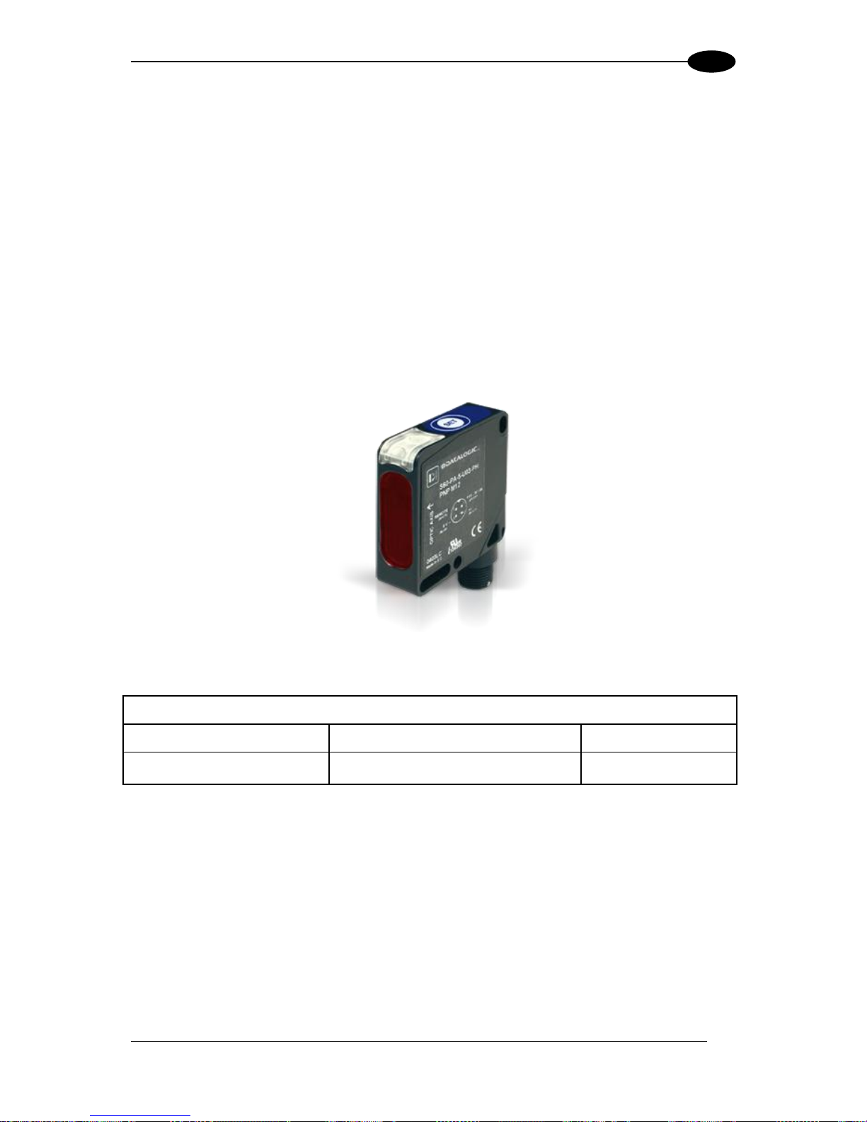
1.7 PHOTOELECTRIC SENSOR
The optional Datalogic Photoelectric Sensor is used in DX8210 barcode scanner systems to
detect the presence of an item in the scanning area.
The photoelectric sensor is used in singulated systems where the packages are separated
by an open space between the trailing edge of one package and the leading edge of the
next. The photoelectric sensor, along with the encoder, enables a programmable transmit
point at a defined distance from the sensor. Without the photoelectric sensor, the barcode
scanner can be run in continuous mode. See 4.5.1 Modify Settings | Global Settings |
Operating Mode.
Depending on the application, these devices may need to be configured differently. While the
photoelectric sensor and tachometer work well with belt conveyors, a special configuration is
needed for tilt-tray and cross-belt sorter applications. See section 3.10 for wiring options.
Figure 7: Photoelectric Sensors
Photoelectric Sensor and Cable (recommended)
MEP-593 PHOTOCELL KIT
PNP (PH-1) with Stripped Wires
93ACC1791
MEP-604 PHOTOCELL KIT
PNP M12-M12 Photocell with M12
connector for SC5000
93ACC0140
Page 20
DS8110 REFERENCE MANUAL
8
1
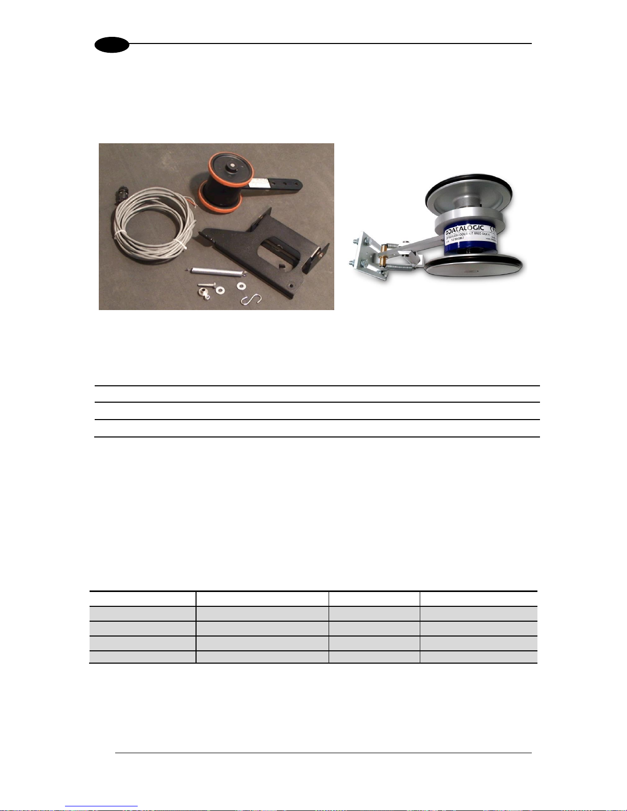
1.8 ENCODER (TACHOMETER)
The tachometer provides a continuous pulse to the system, which provides feedback on
conveyor speed and transmit point, and can be used to help track the package position along
the length of the conveyor. See section 3.11 for wiring options.
Figure 8: Encoder/Tachometer, Mounting Bracket, and Cable
Encoder (Tachometer)
OEK-2 ENCOD KIT
OEK-2 ENC KIT (CAB 10m +SPRING)
93ACC1770
OEK-4 ENCOD KIT
OEK-4 ENC KIT PNP 250PPR + M12-M12 CABLE
95B082040
OEK-4 ENCOD KIT
OEK-4 ENC KIT PNP 250PPR + M12-FREE CABLE
95B082050
1.8.1 Encoder/Tachometer Step Settings
The following table shows the Encoder Step setting used based on pulses per revolution.
The Encoder Step setting is entered in the User Interface (see section 4.5.1 Modify Settings
| Global Settings | Operating Mode – Encoder Step (hundredths of millimeter))
Encoder Model
PPR ( Pulses Per
Revolution)
PPI ( Pulses Per
Inch)
Encoder Step
Setting
OEK-4 (Datalogic)
250
20
63
OEK-2 (Photocraft)
24 2 635
OEK-2
48 4 317
OEK-2
192
16
79
OEK-2
240
20
63
Page 21
INTRODUCTION
9
1
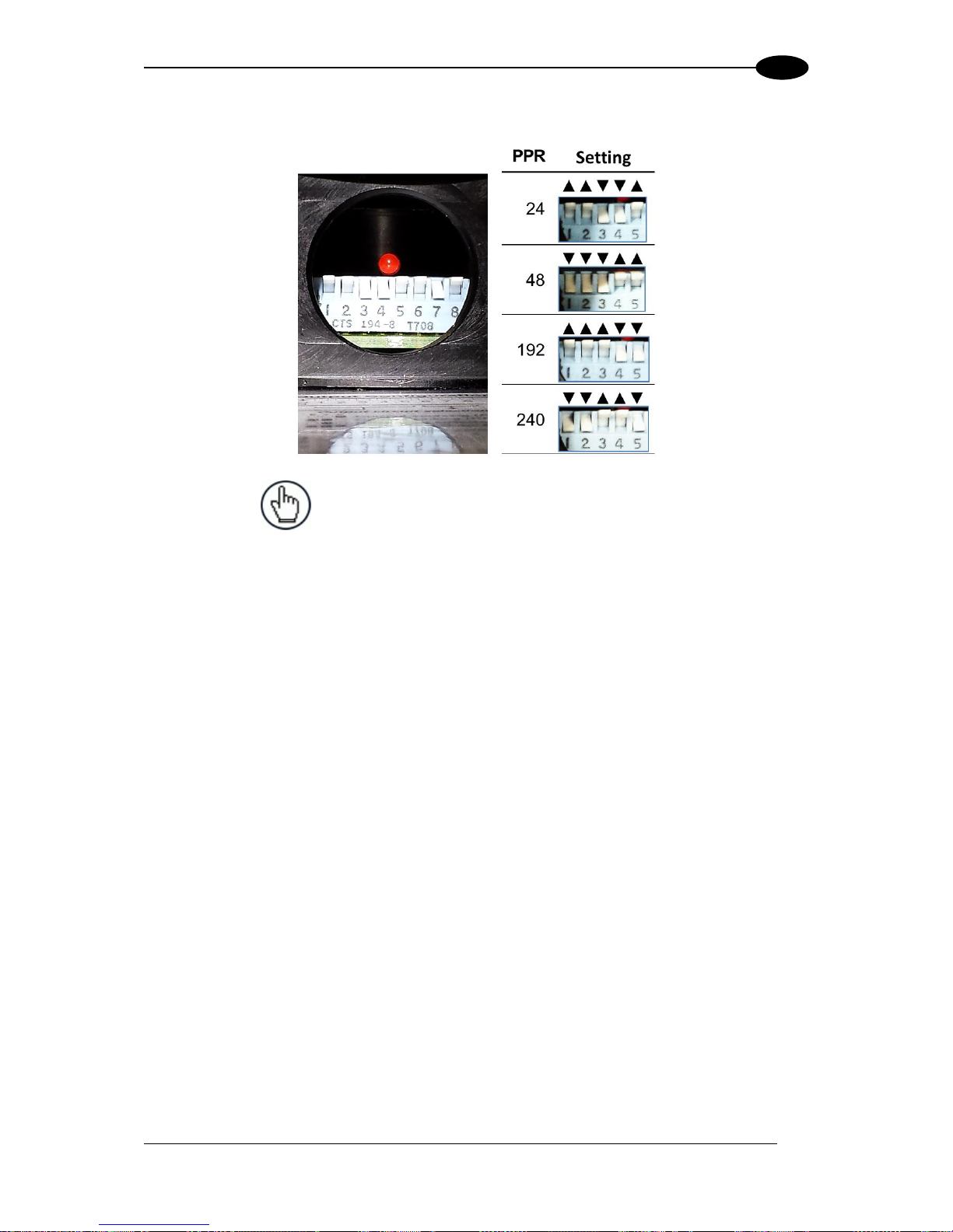
1.8.2 Photocraft Encoder/Tachometer Switch Setting
Figure 9: Photocraft (OEK-2) Encoder/Tachometer Switch Settings
NOTE: Only switches 1-5 are used to set the PPR (Pulses
Per Revolution). Switches 6-8 are used for PNP/NPN
settings as shown in the label on the arm of the encoder.
Page 22
DS8110 REFERENCE MANUAL
10
1
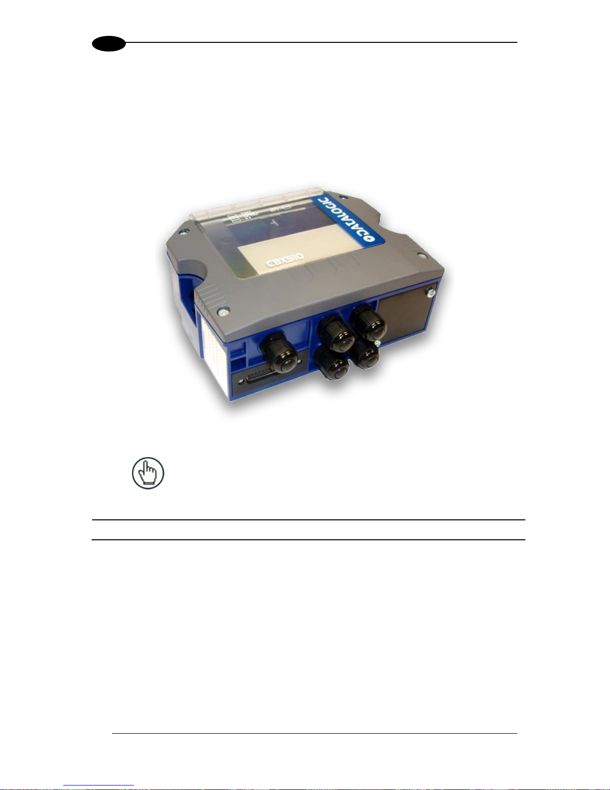
1.9 CBX INDUSTRIAL CONNECTION BOX
CBX Series are industrial connection boxes that can be used to connect the barcode
scanners to an encoder/tachometer, photoelectric sensor, serial devices, relays, or other
peripherals. The CBX510 includes a BM100 backup module, which allows easy parameter
restore and backup operations. The backup module also provides an easy way to upload
existing parameters to a replacement barcode scanner when necessary. See section 3.9.1
for wiring options.
Figure 10: CBX510 Connection Box
NOTE: Scanner operation requires a CBX510 connection box or
SC5000 controller.
Industrial Connection Box
CBX510 Connection Box
CBX510 w/BM100 for DS8110 and DX8210
93A301087
Page 23
INTRODUCTION
11
1
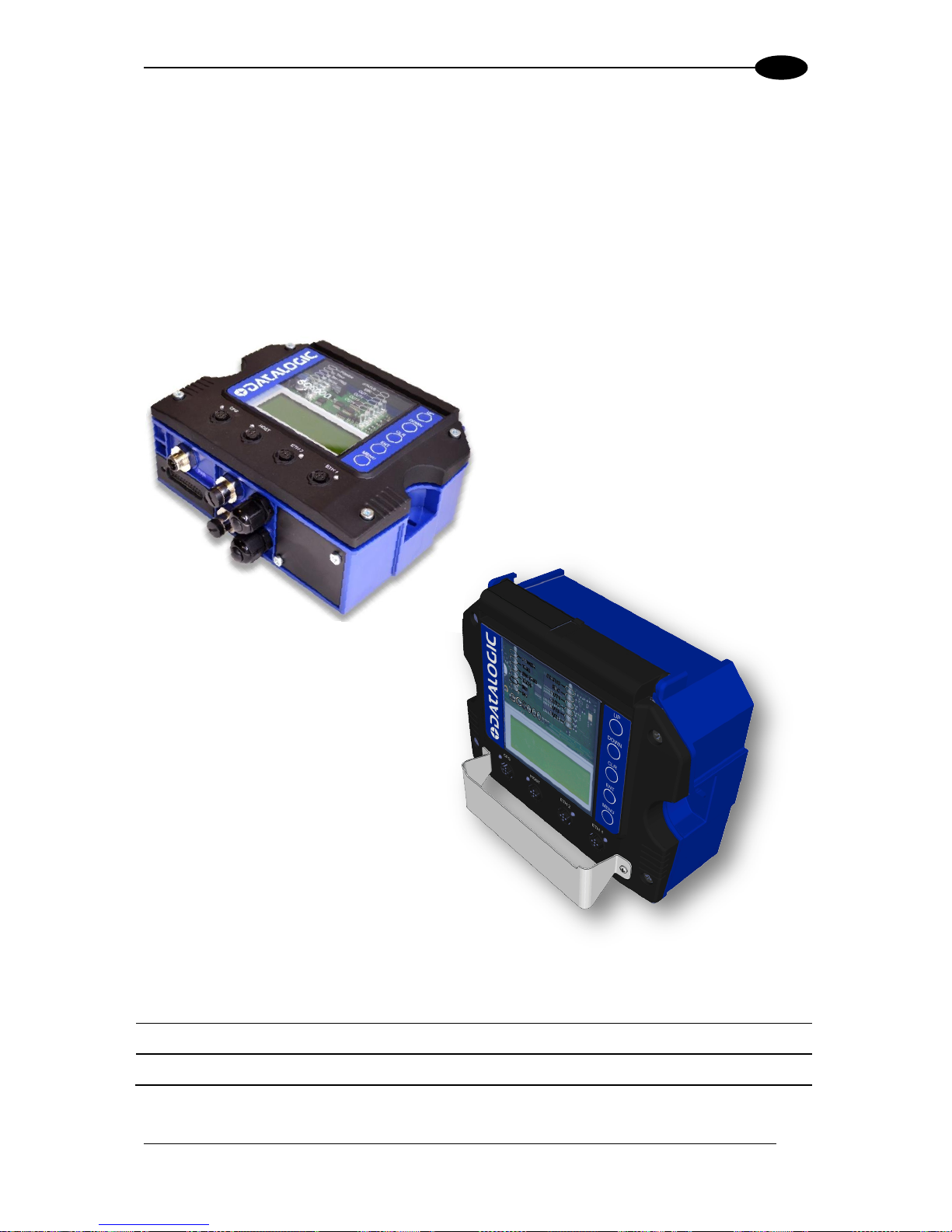
1.10 SC5000 SYSTEM CONTROLLER
The SC5000 Controller offers all the necessary functions to make the phases of installation,
setup, testing, and maintenance of the omni-directional reading array or tunnel easy and
quick.
The SC5000 Controller is fully compatible with DS8110 and DX8210 scanners and its sturdy
mechanical structure makes the SC5000 Controller the ideal solution for industrial
environments. The Controller allows connection to the Trigger and Encoder/Tachometer.
PNP inputs are available via M12 circular connectors, placed on the lower front panel (see
section 3.11).
Figure 11: SC5000 System Controller
System Controller
SC5000-1000 System Controller
Standard
935750001
SC5000-1100 System Controller
Profibus
935750002
Page 24
DS8110 REFERENCE MANUAL
12
2
2 MECHANICAL INSTALLATION
2.1 PREPARING FOR MECHANICAL INSTALLATION
IMPORTANT: Application-specific drawings and documents provided by
Datalogic supersede any contradictory content in this manual.
Before mounting any components, please do the following:
Read all instructions before beginning your installation.
Define and confirm the accuracy of your application’s requirements and structure
position, especially the height of the conveyor from the floor.
Review all installation-specific drawings provided with your equipment.
Review and plan the mechanical installation of all devices used in your application. Be
sure to allow adequate clearance for maintenance.
Review and plan the power requirements for your application.
Check the contents of the shipping cartons against the packing list.
Record all product serial numbers.
NOTE: : Refer to the Chapter 3 Electrical Installation and Reference
Documentation for details on connecting your barcode scanners to other
devices in the system.
WARNING: Electrical Installation by Qualified Service Technicians Only!
Procedures may involve exposure to high-voltage. A trained and authorized
technician must perform these procedures. Do not attempt to perform any
electrical installation procedures unless you are a trained technician.
IMPORTANT: DS8110 barcode scanners contain electronics that may be
affected by electrostatic discharge (ESD). To prevent personal injury or
damage to the unit, please follow the safety precautions and warnings found
in the References section at the beginning of this manual. Failure to follow
these precautions may void your warranty.
WARNING: When installing several scanners, take care to position them so
that no laser beam enters the reading window of other scanners. This
condition could occur more frequently for side mounted applications. If these
precautions are not followed, read rate could be negatively affected. To
resolve this problem, it is sufficient to slightly change the inclination and
position of one of the two scanners involved if possible.
Page 25
MECHANICAL INSTALLATION
13
2
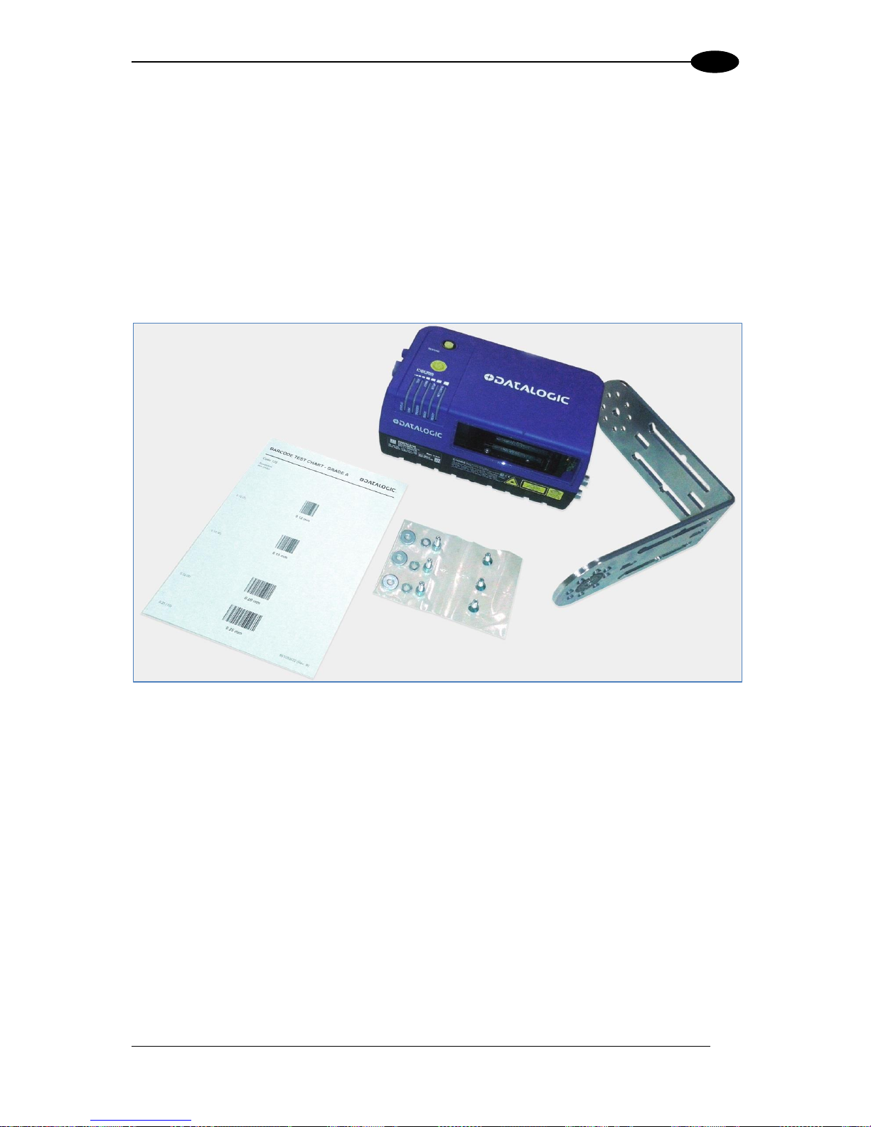
2.2 UNPACKING INSTRUCTIONS
Verify that the DS8110 barcode scanners and all the parts supplied with the equipment are
present and intact when opening the packaging; the list of parts includes:
DS8110 reader
L-bracket
Mounting screws (two types) and washers
Barcode Test Chart
Figure 12: Package contents
Page 26

DS8110 REFERENCE MANUAL
14
2
2.3 INSTALLATION SEQUENCE
NOTE: Everything should be MECHANICALLY INSTALLED before
performing any ELECTRICAL INSTALLATION.
See Chapter 3 Electrical Installation for electrical installation details.
To complete mechanical installation and setup, you must:
Review the details of your application’s requirements
Erect mounting structure or other supporting structures
Determine and mark the Mounting Bracket location(s)
Mount the bracket to the mounting structure
Mount the DS8110 to its mounting bracket
Mount the photoelectric sensor to the mounting structure (optional)
Mount the tachometer to the mounting structure (optional)
Mount the CBX connection box to the mounting structure
Mount the SC5000 to the mounting structure
Complete electrical installation (See Chapter 3)
Align the DS8110 for proper operation
Configure the DS8110 (See Chapter 4)
Check DS8110 operations (See Chapter 5)
Page 27

MECHANICAL INSTALLATION
15
2
2.4 WHAT YOU NEED TO KNOW ABOUT YOUR APPLICATION
To assure you get optimal performance out of your DS8110, it must be installed to meet the
complete needs of your application. Therefore, take the time to learn the details of your
application. The better you know your application, the easier it is to apply the DS8110’s
capabilities to meet your application’s requirements.
Below is what you will need to know before you can begin installation:
Conveyor Specifications
Conveyor type: Belt, tilt-tray, cross belt, other?
What is the conveyor width?
What is the conveyor speed?
Does conveyor speed vary or is it constant?
Product Specifications
Are the packages being transported always singulated (not touching) or non-
singulated (possibly touching)?
How many different product sizes may be involved?
Are products justified: toward/away from reader, centered, or variable?
Application Specifications
How will the barcode information be used in your application?
What are your communication requirements?
While it is nearly impossible to cover all application configurations, the next several pages
provide the basics on determining how to mechanically install your DS8110. If you need
additional assistance, feel free to contact your sales representative or customer service
(www.datalogic.com).
Page 28
DS8110 REFERENCE MANUAL
16
2
2.5 INSTALLATION
2.5.1 Dimensions and Clearances
The overall dimensions of the DS8110 are 216 x 96 x 127 mm [8.5 x 3.8 x 5 in].
IMPORTANT: The DS8110 is a sealed, unventilated unit. Mounting the unit
with 300mm [12”] of clearance (front, top, and sides) is recommended for
cooling and ease of maintenance.
2.5.2 Physical Support Requirements
For details on the weight of the barcode scanners, see Chapter 8, Technical Features.
Multiple-head systems may include further details on the physical support requirements with
any application-specific documentation provided.
2.5.3 Vibration Limitations
See Chapter 8, Technical Features.
Page 29

MECHANICAL INSTALLATION
17
2
2.5.4 General Mounting Guidelines
It is important that you follow these general precautions when installing, setting up, operating,
maintaining, troubleshooting, or replacing any Datalogic products, parts or related
equipment.
As you plan and install your DS8110 barcode scanning system application, be sure to keep
the following guidelines in mind:
All mounting structure assembly and equipment installation can be performed by one
installer.
Determine the proper orientation and position of the barcode scanner.
Leave adequate clearances (approximately 300 mm [12 inches]) for wiring.
Route wires carefully to reduce or minimize electrical noise. When power and
communication wiring must cross, make their intersection perpendicular.
Proper grounding limits the effects of noise due to Electromagnetic Interference (EMI).
Page 30

DS8110 REFERENCE MANUAL
18
2
2.5.5 Mounting Structure Considerations
Your first task is to mount your DS8110 barcode scanner. You can provide your own
mounting structure or Datalogic can design one for you. We recommend using a Datalogic
mounting structure for standard applications.
Your mounting structure must provide the following capabilities:
It is adjustable enough for you to move your unit to the optimum position for proper
scanning.
It allows a technician access to the barcode scanner while it is mounted.
It must be as vibration free as possible so as not to affect the scanning accuracy.
It is constructed of steel or aluminum.
It provides approximately 300 mm [12 inches] minimum clearance on all sides. This
clearance is necessary to provide proper ventilation, allow access to all panels of the
barcode scanner, and allow room for proper servicing.
Page 31

MECHANICAL INSTALLATION
19
2
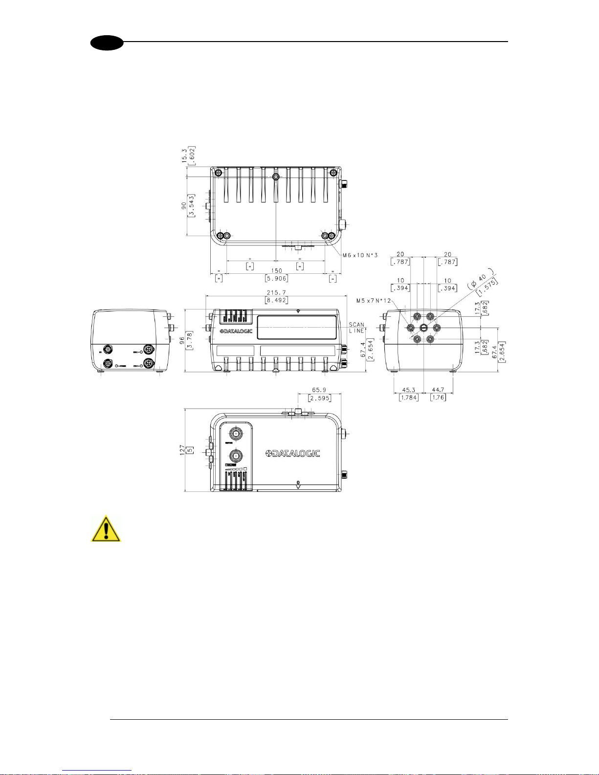
2.5.6 Mounting the Scanner
The DS8110 can be installed to operate in any position. There are 12 screw holes (M6 X 8)
on the sides of the scanner for mounting. The diagram below can be used for installation;
refer to reading diagrams (See 5.10) and any application drawings for correct positioning of
the scanner with respect to the reading zone and scanner orientation.
Figure 13: DS8110 mounting dimensions with L-bracket
Page 32

DS8110 REFERENCE MANUAL
20
2
The L-bracket included with the DS8110 scanner allows it to be installed in the most suitable
position for your application. The L-bracket is mounted to the scanner as shown below:
Figure 14: DS8110 mounting bracket assembly with countersunk screws
Figure 15: DS8110 mounting bracket assembly with cap screws, lock washers, and flat
washers
Page 33

MECHANICAL INSTALLATION
21
2
Figure 16: DS8110 mounting angles
If the DS8110 needs to be mounted at a 5-degree angle or within 5-degrees of the angles
shown in Figure 16: DS8110 mounting angles (+/- 5, +/-25, or +/-35-degrees), mount it to
the opposite end of the L bracket as shown below:
Figure 17: DS8110 5-degree mounting option
Page 34

DS8110 REFERENCE MANUAL
22
2
2.5.7 Positioning the Scanners
The DS8110 barcode scanners are able to decode barcode labels at a variety of angles;
however significant angular distortion may degrade reading performance.
When mounting the scanners, take into consideration these three ideal label position angles:
Pitch 0°, Skew 0° to 45° and Tilt 0°.
Follow the suggestions for the best orientation:
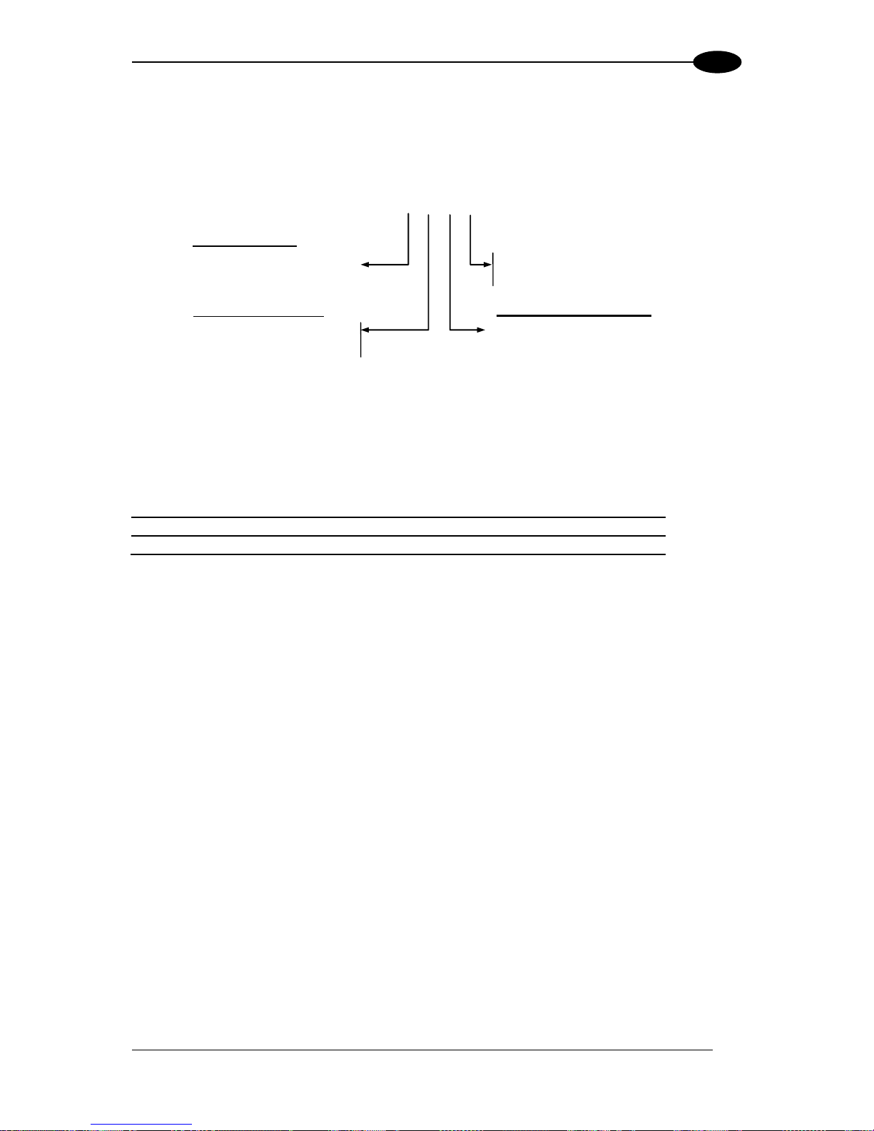
Figure 18: Tilt, Pitch, and Skew
Tilt
Pitch
Skew
Page 35

ELECTRICAL INSTALLATION
23
3
3 ELECTRICAL INSTALLATION
3.1 PREPARING FOR ELECTRICAL INSTALLATION
Before mounting any components, please do the following:
Read all instructions before beginning your installation.
Observe all electrical safety requirements discussed in the Introduction to this manual.
Define and confirm the accuracy of your application’s requirements.
Review all installation-specific drawings.
Review and plan the power requirements for your application.
Review and plan the communications requirements for your application.
IMPORTANT: The content of this manual may be superseded by any
customer-specific documentation provided by Datalogic. Before proceeding
with any installation procedures, be sure to review ALL documentation,
especially content that contains details specific to your installation.
NOTE: Everything should be MECHANICALLY INSTALLED before
performing any ELECTRICAL INSTALLATION. See Chapter 2 for
mechanical installation details.
Most DS8110 applications are shipped with the CBX connection box and
all the necessary cabling required to electrically install the system. If your
system requires custom-length cables or other special wiring,
documentation specific to these requirements has been provided in your
shipment. This special documentation supersedes any contradictory content
in this manual.
NOTE: To reduce the possibility of damage to the unit, check all cabling
between the scanner and other devices for accuracy.
WARNING: Electrical Installation by Qualified Service Technicians Only!
Procedures may involve exposure to high-voltage. A trained and authorized
technician must perform these procedures. Do not attempt to perform any
electrical installation procedures unless you are a trained technician.
IMPORTANT: The DS8110 barcode scanners contain electronics that may be
affected by electrostatic discharge (ESD). To prevent personal injury or
damage to the unit, please follow the safety precautions and warnings found
in the References section at the beginning of this manual. Failure to follow
these precautions may void your warranty.
Page 36

DS8110 REFERENCE MANUAL
24
3
3.2 CONNECTING A DS8110 SCANNER
To install a DS8110 barcode scanner, follow this sequence:
Complete mechanical installation (See Chapter 2.)
Complete electrical installation (See wiring illustrations provided in this chapter.)
Observe all electrical safety requirements outlined in this chapter.
Ground the mounting structure to protective earth (PE) ground.
If used, wire the photoelectric sensor (or other trigger) to the CBX510 connection
box/SC5000.
Wire the tachometer to the CBX510 connection box/SC5000 (if used).
Wire serial ports to the CBX510 connection box/SC5000 if needed.
Connect the M12 end of the Ethernet cable to the scanner’s HOST port and network
switch as required by your application.
Connect the scanner to its power supply.
Connect the power supply to the power source.
Setup / check scanner operations (See Chapter 5.)
Page 37

ELECTRICAL INSTALLATION
25
3
3.3 TYPICAL CONNECTION BLOCK DIAGRAMS
3.3.1 Single DS8110 Barcode Scanner to CBX510
Figure 19: Single DS8110 to CBX510
Page 38

DS8110 REFERENCE MANUAL
26
3
3.3.2 Master/Slave Array with CBX510
Figure 20: Master/Slave Array (Tunnel) with CBX510
Page 39

ELECTRICAL INSTALLATION
27
3
3.3.3 DS8110 Barcode Scanners in an Array with SC5000 Master
In an array (tunnel) using the SC5000 Controller, the chain of scanners completes a circle
from and to the SC5000 Controller via ETH1 and ETH2. In this scenario, if one scanner fails,
communication from the other scanners to the SC5000 Controller is not interrupted.
Figure 21: DS8110 Array (Tunnel) with SC5000
Figure 22: DS8110 Array (Tunnel) to SC5000 (alternate with CBX)
Page 40

DS8110 REFERENCE MANUAL
28
3
3.4 GENERAL ELECTRICAL INSTALLAION GUIDELINES AND
PRECAUTIONS
It is important that you follow these general precautions when installing, setting up, operating,
maintaining, troubleshooting or replacing any Datalogic products, parts or related equipment.
As you plan and install your scanner(s), be sure to keep the following guidelines in mind:
Determine the scanner is in the proper location as outlined in Chapter 2.
Leave adequate clearances (approximately 300mm [12 inches]) for wiring.
Route wires carefully to reduce or minimize electrical noise.
IMPORTANT: When planning your installation wiring, remember all power
connections must be quick-disconnect. For PERMANENTLY CONNECTED
EQUIPMENT a readily accessible disconnect device must be incorporated
in the building installation wiring. For PLUGGABLE EQUIPMENT the
socket-outlet must be installed near the equipment and must be easily
accessible
WARNING: To assure no ESD damage will occur, be sure to observe the
precautions outlined in the Introduction to this manual.
IMPORTANT: Ground the mounting structure to safety ground (protective
earth ground (PE)). See wiring recommendations for safety ground.
Page 41

ELECTRICAL INSTALLATION
29
3
3.5 DS8110 CONNECTOR PANELS
After completing mechanical installation, use this section to properly wire your scanners for
optimal performance in your application. DS8110 wiring connections are made to the
connector panel and through the CBX connection box (connected to the I/O port of the
scanner). In most applications, the cable connections to the scanner will include:
1. I/O (Connects directly to the 25-pin D type connector on the CBX connection box)
2. POWER
3. ETH 2 (Setup or EBC scanner network)
4. ETH 1 (Host or EBC scanner network)
Figure 23: DS8110 Connector Panel
Route wiring from the scanner’s connector panel through the wiring channels (if available) on
the Datalogic mounting structure when interconnecting cables to other devices.
Figure 24: Wiring Channels
Page 42

DS8110 REFERENCE MANUAL
30
3
3.6 CONNECTING A PC TO THE DS8110
During initial setup, a PC (laptop) may be connected to the DS8110 with a M12 to RJ45
cable. Screw the M12 connector to the ETH 2 port of the scanner and plug the RJ45 into the
Ethernet port of your PC. If the ETH 2 port is in use, ETH 1 port can be used. For information
on connect to the User Interface, see Chapter 4.
NOTE: ETH2 is the Setup port, ETH1 is the HOST port.
NOTE: A laptop can only communicate to a scanner that is connected to a
CBX Connection Box or SC5000 Controller.
NOTE: Parameters for tunnel are set up in MASTER scanner (or SC5000
Controller) only.
3.7 POWER CONNECTOR PIN-OUT TABLE
A recommended power supply and cabling is available with the DS8110 and DX8210 (and
SC5000 Controller). However, if your installation requires custom power supply wiring, the
pin-outs of the unit power connector are provided below for your convenience.
NOTE: When using a DS8110 barcode scanner, no power supply is
required for the CBX510 connection box. All power and some
communication options are fed to the CBX510 through the scanner’s 17-pin
I/O connector to the CBX510 25-pin connector using the cable provided.
24V - - - 4A MAX
POWER Input
Unit Connector (shown)
Mating cable connector
5-PIN M12-TYPE MALE
5-PIN M12-TYPE FEMALE
MALE 5-PIN M12-TYPE
Pin
Function
1
+24 VDC
2
n/c 3 dc return
4
n/c
5
protective earth (chassis)
Page 43

ELECTRICAL INSTALLATION
31
3
3.8 POWER CONNECTIONS
IMPORTANT: When planning your installation wiring, remember all power
connections must be quick-disconnect.
CAUTION: While performing the following wiring connection procedures, be
sure to follow all safety procedures regarding high-voltage as outlined in the
Introduction to this manual. No power should be applied to any device until
all wiring is completed and checked for accuracy.
IMPORTANT: The socket-outlet must be installed near the scanner. The
outlet must be a readily accessible disconnect device.
GROUND: Ground the scanner to safety ground (protective earth ground
(PE)). See wiring recommendations for safety ground.
The CBX connection boxes provide flexible connectivity to a range of I/O devices as well as
serial hosting. The DS8110 connects to the CBX via its I/O port using a single 17-pin M12 to
25-pin D cable. The CBX connection box also provides space for an optional BM100 backup
module (recommended) for parameter storage, allowing quick replacement and configuration
of the scanners.
In a system with multiple scanners and other devices required in a scanning array (tunnel),
an SC5000 Controller serves as the system Master and provides communications between
devices and to the Host. Complete installation information for the SC5000 Controller is
available in the SC5000 System Controller Reference Manual available at
www.datalogic.com.
Page 44

DS8110 REFERENCE MANUAL
32
3
3.9 CBX510 CONNECTION BOX
Complete installation information for the connection box is available in the CBX510
Installation Manual available at www.datalogic.com. A simple drawing of the interior of the
box is shown below.
Figure 25: CBX510 Interior
3.9.1 Wiring Into the CBX510 Connection Box
WARNING: DO NOT connect a separate power source to the CBX510
connection box. The CBX510 receives its power through its connection to
the DS8110/DX8210 Barcode Scanner. Connecting a separate power
source will be detrimental to the system operation.
IMPORTANT: DISCONNECT POWER from the scanning system and
CBX510 before wiring any components.
Loose-lead cables must pass through the water-tight seals in the base of the CBX510
connection box. Insert the cables allowing enough slack for the individual wires to reach the
appropriate pin block connectors. Securely tighten the water-tight seals after the cables have
been inserted.
Insulation on individual wires should be removed to expose 13 mm [0.5 inch] of bare metal
before inserting into the pin block.
Page 45

ELECTRICAL INSTALLATION
33
3
3.10 PHOTOELECTRIC SENSOR CONNECTIONS TO CBX510
Barcode scanning applications may use a Datalogic photoelectric sensor as a trigger device.
The photoelectric sensor is wired directly into the CBX510 terminal.
If your application uses a trigger other than the one specified by Datalogic, follow the
appropriate wiring diagram to assure proper wiring.
NOTE: To confirm the photoelectric sensor is functioning properly, watch
the TRIG LED while the photoelectric sensor’s beam is blocked. The
Datalogic photoelectric sensor also includes a status LED.
The following diagrams illustrate standard recommended wiring of the Photoelectric Sensor
to the CBX510 terminal block.
Page 46

DS8110 REFERENCE MANUAL
34
3
3.10.1 Photoelectric Sensor (NPN)
Figure 26: Photoelectric Sensor Wiring (NPN Output)
Page 47

ELECTRICAL INSTALLATION
35
3
3.10.2 Photoelectric Sensor (PNP)
Figure 27: Photoelectric Sensor Wiring (PNP Output)
Page 48

DS8110 REFERENCE MANUAL
36
3
3.11 TACHOMETER WIRING TO CBX510
DX8210 applications over a conveyor belt use an accessory tachometer and mounting kit.
The following diagrams illustrate standard recommended wiring of an encoder to the CBX510
terminal block.
3.11.1 Encoder/Tachometer Wiring for NPN Output (two models)
Figure 28: OEK-2 Encoder/Tachometer Wiring (NPN Output)
NOTE: Some tachometers may
have a different color coding:
(+V)
Red or White/Orange
(Signal)
White or White/Blue
(Ground) Black or Orange/White
Page 49

ELECTRICAL INSTALLATION
37
3
Figure 29: OEK-4 (95B082050) Encoder/Tachometer Wiring (NPN Output)
Page 50

DS8110 REFERENCE MANUAL
38
3
3.11.2 Encoder/Tachometer Wiring for PNP Output (two models)
Figure 30: OEK-2 (93ACC1770) Encoder/Tachometer Wiring (PNP Output)
NOTE: Some tachometers may
have a different color coding:
Red (+V)
or White/Orange
White (signal)
or White/Blue
Black (ground) or Orange/White
Page 51

ELECTRICAL INSTALLATION
39
3
Figure 31: OEK-4 (95B082050) Encoder/Tachometer Wiring (PNP Output)
Page 52

DS8110 REFERENCE MANUAL
40
3
3.12 DIGITAL OUTPUT CONFIGURATION TO CBX510
The CBX510 includes an OUTPUTS block for wiring relays as needed for external
accessories. The User Interface Modify Settings | Digital I/O window includes options for
outputs 1 and 2 with Primary and Secondary Activation Event options including Complete
Read, Partial Read, No Read, Trigger On, Trigger Off, Multiple Read, Right/Match, and
Wrong/No Match.
Schematics for Isolated and Non-Isolated digital outputs are provided below.
Outputs 1 - 3
Figure 32: OUTPUTS Block
Maximum Voltage 30 V
Collector Current (pulse) 130 mA Max.
Collector Current (continuous) 40 mA Max.
Saturation Voltage (VCE) 1 V at 10 mA Max.
Maximum Power Dissipation 90 mW at 50°C (Ambient
temperature)
3.12.1 Unpowered Outputs
Figure 33: Unpowered Outputs
NPN
PNP
Page 53

ELECTRICAL INSTALLATION
41
3
3.12.2 Powered Outputs
Figure 34: Powered Outputs
NPN
PNP
Page 54

DS8110 REFERENCE MANUAL
42
3
3.13 CONNECTING TO THE SC5000 SYSTEM CONTROLLER (OPTIONAL)
In larger scanning arrays (scanning tunnels), an SC5000 controller can act as the system
master and support up to 31 slave DS8110/DX82110 barcode scanners in an Ethernetbased connection loop (EBC). SC5000 wiring connections are made to the front and bottom
connector panels. In most applications, the cable connections to the scanner will include:
1. CFG (Configuration via laptop Ethernet cable)
2. HOST
3. ETH 1 (EBC scanner network)
4. ETH 2 (EBC scanner network)
5. POWER
6. I/O (Connects directly to the 25-pin D type connector on the CBX connection box)
7. ENC (PNP Encoder/Tachometer)
8. TRG (PNP Trigger/Photoelectric Sensor)
9. Water-tight connectors0.
Figure 35: SC5000 Bottom Panel Connectors
Complete installation information for the SC5000 Controller is available in the SC5000
System Controller Reference Manual available at www.datalogic.com.
Page 55

ELECTRICAL INSTALLATION
43
3
3.14 CHECK SCANNER INSTALLATION
After completing the installation of your barcode scanner, confirm that the barcode scanners,
CBX connection box and/or SC5000 Controller have been properly installed mechanically
and electrically. Use the Installation Sequence at the beginning of this chapter and your
application specifications to check your installation.
Page 56

DS8110 REFERENCE MANUAL
44
4
4 USER INTERFACE
4.1 GETTING STARTED
The DS8110/DX8210 barcode scanners are designed for ease-of-setup. The
DS8110/DX8210 User Interface is a browser-based application you will use to define
operating parameters, monitor read quality, construct output messages, and view
diagnostics. The User Interface enables you to easily configure, fine-tune, and monitor your
scanner’s operation.
This User Interface provides ease-of-use for any operator level.
4.1.1 Prerequisites
Before setting up your barcode scanner you will need the following:
Computer
Laptop
Browser
Internet Explorer 11 (or later)
Firefox 30 (or later)
Chrome 36 (or later)
Java
Java version 8 (or later)
NOTE: If the Diagnostic | Monitor page does not run, you may
need to create an exception in the Java Control Panel.
To do this:
If the Diagnostic | Monitor page does not run, you may need to
create an exception in the Java Control Panel.
To do this:
1. Click the Start/Home button and type Configure Java in
the search field. Select the Java Control Panel from the
search results. The Java Control Panel opens.
2. Click the Security Tab to open it.
3. Under Exception Site List, click Edit Site List… The
Exception Site List window opens.
4. Click Add.
5. Enter the IP Address for the system/scanner in the field
provided as follows: http://10.27.154.125/ (but matching
your system’s IP Address)
6. Click OK. The Monitor page should now load. 0.
Page 57

USER INTERFACE
45
4
4.1.2 Starting the User Interface
To access the User Interface:
NOTE: Before starting up or testing the scanner, it must be connected to
a CBX510 Connection Box (see section 3.9.1) or an SC5000
Controller (see section 3.13) depending on the system configuration.
1. Connect your computer to the scanner’s ETH 2 port using either the CAB-ETH-M0x M12IP67 ETHERNET CABLE or CBL-1534-0.2 ADAPT.CABLE ETH M12-TO-RJ45F. If the
ETH 2 port is taken, ETH 1 can be used.
2. Turn on your computer.
3. If you are connecting to a stand-alone unit (not connected to an in-house network), you
must configure your PC’s IP Address to be in the same network as the scanner’s (or if
used, controller’s) IP Address.
To change your PC’s IP Address:
a. From the desktop, click the Start button, and then select Control Panel.
b. Type adapter in the search box, and then from the results, under Network and
Sharing Center, click View network connections.
c. Right-click Local Area Connection, and then select Properties.
d. Select the Networking tab. Under This connection uses the following items,
click Internet Protocol Version 4 (TCP/IPv4), and then click Properties.
e. Select Use the following IP address.
f. In the IP address field, type the first 3 octets of the IP address of the reader/controller
unit.
g. For the last octet, type a number that differs from the last octet in the
reader/controller’s IP address. The actual number used is not important as long as it
does not match that of the reader/controller.
Example: If the barcode scanner’s IP Address is 192.168.3.100, set your PC’s IP
Address to 192.168.3.101.
h. In the Subnet mask field, type 255.255.255.0
i. In the Default gateway field, type 0.0.0.0
j. Click Okay.
4. Open a web browser and enter the IP address for the DS8110/DX8210. If the correct IP
address is entered, the DS8110/DX8210 Log On window will appear.
The default setup IP address for all DS8110/DX8210 units is: 192.168.3.100 (setup) and
172.27.101.220 (Host).
Page 58

DS8110 REFERENCE MANUAL
46
4
5. Enter the Password (default is DLA) for your system in the fields provided.
6. Select a language from those available in the Language drop-down list.
7. Select METRIC or IMPERIAL from the Units drop-down list.
8. Click Log On. 0.
If the password is valid, the application enables all functions available to the user and
displays the System Info window.
If the password is not valid, the application displays a results box with the message,
“Incorrect Password.” Click OK to return to the Log On window and enter the correct
user name and password. I you don’t know the password, contact your system manager.
0.
To log out of the User Interface:
Click at the upper right corner of the User Interface window to Log Out. When logged
out, the Log On window will appear.
Page 59

USER INTERFACE
47
4
4.2 USER INTERFACE BASICS
4.2.1 DS8110/DX8210 User Interface Menu Tree
The functions that you can select are displayed in a menu tree on the left–hand side of the
reader/controller User Interface. The function list is organized much like the hierarchy of a file
system, where you can expand items that are preceded by a box ( ) to further sub–levels
until you find a function of interest.
Sub–levels appear indented below the items from which they are expanded. Clicking the box
again will collapse that branch of the menu. You can expand no further when an item is not
preceded by a box.
The reader/controller User Interface menu tree appears with no items expanded. Click the
folders to display the active window for the setup function and/or expand the folders to view
any additional setup features.
4.2.2 Entering Text Using the Text Entry Tool
In cases where text needs to be entered to create message headers, trailer, custom
messages, or for other reasons, the Text Entry Tool pencil icon “ ” will be displayed.
Click to open the Text Entry Tool.
You can enter text in the text field by typing, or click on the character buttons to create your
message. Select the Extended Characters check box to reveal a new set of control
characters.
Click Submit to save your text to the origin window text field, or click Cancel to return to
origin window without transferring text.
NOTE: The Text Entry Tool is needed to enter unprintable/untypable
characters. For example, <CR> is a single character presented as a
string for more easily reading.
The character must be entered with the tool, if typed normally it will be
recognized as a string and not as a single character.
Page 60

DS8110 REFERENCE MANUAL
48
4
4.2.3 Getting Help
DS8110/DX8210 User Interface provides complete online help.
To access the complete help system:
Select Utilities | Help in the User Interface menu tree. The help Welcome window appears.
The Welcome page provides important product information as well as three ways to find
specific help information: Contents, Index, and Search.
To display contextual help for a current window:
1. Click the Help Icon displayed at the top right of the screen. A help window
appears, providing you with information for that specific page.
2. Click the Show link in the upper left corner of the help window to access Contents, Index,
and Search options.0.
Page 61

USER INTERFACE
49
4
4.3 MODIFY SETTINGS
Use the Modify Settings Menu Tree selections during initial setup to configure your scanning
system. If necessary, you can later make modifications to the configuration using the same
menu selections.
Page 62

DS8110 REFERENCE MANUAL
50
4
4.4 MODIFY SETTINGS | SYSTEM INFO
Use System Info to identify and name the scanning system (whether it includes one scanner
or an array), indicate Master or Standalone systems, discover the scanners included in the
system, and distribute software from the Master scanner to Slave scanners in the system.
To view and edit system information:
1. In the tree menu under Modify Settings, click System Info. The System Info window
opens.
2. Enter the appropriate information in the form as described below:
Field Name
Action/Definition
System Info
System
Description
Enter a name to identify this scanning system in the text field.
Role
Select Standalone or Master from the drop-down list. Standalone (not
controllers) indicates a scan point with a single barcode scanner. Master
indicates that the system is made up of more than one barcode scanner in a
master and slave configuration.
NOTE: The SC5000 Controller will always be
shown as Master and cannot be changed.
Enable
Automatic Slave
Replace
There are two way to replace a defective scanner :
If the check box is not selected: The replacement will be done only pressing
the RESTORE (see section 4.8.1) key on the scanner or using the Edit dropdown.
If the check box is selected: The replacement will be completely automatic.
This will work also as Hot-Automatic-Replacement without turning the system
power off and on.
Page 63

USER INTERFACE
51
4
Master Tools
Discover
Scanners
Click Discover Scanners to automatically find all of the scanners in an array. The
discovered scanners will be listed in the Device Information portion of the
window. This step is only done during initial configuration and is not a
troubleshooting option.
Distribute
Software
Click Distribute Software to send the current software residing on the master
scanner to all of the slave scanners listed in the Device Information section of
the window.
Device Information
Status
Green = No errors and ready to read
Gray = Unit not connected (unit not seen by master)
Red = Error. If you click on the red circle it will take you to the status viewer page
for more info on the error
Model
Displays an image of the scanner/controller model
Dev
Displays the system designation for the device
MAC Address
Displays the MAC Address (Media Access Control Address) for the device
Software version
Displays the device installed software version.
Description
Enter a user-defined description of the device.
ID
Click ID to visually identify a scanner in an array/tunnel. When clicked, all the
scanner lasers will turn off except for the selected scanner, whose laser will blink
for 20 seconds.
Edit
Select to Remove, Reassign, Add, or Replace from the Edit drop-down list to
complete the following actions:
Remove: When selected, you can select the scanner to remove from the
Dev/MAC Address drop-down list. Click OK to remove the selected scanner
from the system.
Reassign: When selected, the Dev column of the selected slave scanner
(selected with ID) presents a drop-down list of Dev numbers. Select a
different number to reassign the scanner.
Add: This is an option under the Edit drop-down list in the Unconfigured
Devices section of the screen. Click OK to add the selected device to the
system.
Page 64

DS8110 REFERENCE MANUAL
52
4
3. When you have finished making changes, click Update to save or click Reset to revert to
the previously saved values. 0.
Replace: This is an option under the Edit drop-down list in the
Unconfigured Devices section of the screen. When selected, you can select
from a list of slave scanners (Those with a gray indicator, meaning the unit is
not connected) in the system using MAC Address and Dev drop-down lists.
Click OK to replace the selected scanner with the Unconfigured Device.
Page 65

USER INTERFACE
53
4
4.5 MODIFY SETTINGS | GLOBAL SETTINGS
Use the Global Settings menu tree selections during initial setup to configure
your DS8110/DX8210 Barcode Scanning System. Global settings are applied to the
system Master, and then distributed by the Master Scanner to the Slave devices. If
necessary, you can later make modifications to the global system settings using the same
menu selections.
Page 66

DS8110 REFERENCE MANUAL
54
4
4.5.1 Modify Settings | Global Settings | Operating Mode
Use Operating Mode to select an operating mode and configure that modes related
parameters. The three operating modes available are On Line, Continuous, and
PackTrack, and the available settings differ depending on the operating mode selected.
To edit the system Operating Mode:
1. In the tree menu under Modify Settings, navigate to Global Settings | Operating
Mode. The Operating Mode window opens.
Page 67

USER INTERFACE
55
4
2. Enter the appropriate information in the form as described below:
Operating Mode
Select On Line, Continuous, or PackTrack from the Operating Mode
Selection drop-down list.
On Line
Select 1 Input Used, 2 Inputs Used, or Serial from the On Line Options dropdown list. Each selection has a different set of parameters as described below. In
this operating mode, the reading phase is defined as the time between the Phase
ON and Phase OFF events. The Phase events can be signals coming from one
or two external presence sensors connected to the scanner inputs or serial
start/stop strings sent from the host over the serial interface or Ethernet input.
1 Input Used
The reading phase takes place during the active phase of the
presence sensor, when the scanner tries to acquire and correctly
decode the code. If the operation is successful, the barcode
characters are transmitted on the serial interface or Ethernet input
in the format defined by the current configuration and the right
output event is raised at the end of the photoelectric sensor’s active
phase. If a code cannot be decoded, a no read message is sent
and the no read event is raised at the end of the photoelectric
sensor’s active phase.
Trigger Source
Start Input
Number
Select the Input Number from the selections
available in the drop-down list.
This option defines the numbered input that will
start the trigger cycle.
Start Input
Active Level
Select Active Open or Active Closed from the
drop-down list.
Active Open: The input is active when
there is no current flowing through IN
pins. The input from the trigger source is
normally closed. The scanner goes into
trigger mode when the input source is
opened.
Active Closed: The input is active when
current flows through IN pins. The input
from the trigger source is normally
opened. The scanner goes into trigger
mode when the input source is closed.
Page 68

DS8110 REFERENCE MANUAL
56
4
Reading Phase
Timeout
Select the check box to define a timeout for the
On Line Serial mode and the On Line 1 Input
mode.
Timeout (ms)
Enter a timeout in milliseconds (from 40 to 15000
ms) in the field provided. The Timeout represents
the period of time for the reading phase.
Timeout
Counting
From
Select Start or Stop from the drop-down list.
When Start is selected, the Timeout
used to determine the reading phase will
begin from the Start Input or Serial Start
String (normal operation)
When Stop is selected, the Timeout
used to determine the reading phase will
begin from the Stop Input or Serial Stop
String (effectively extending the reading
phase).
Verifier Settings
Verifier Enable
Select the check box to enable the Code Verifier
operating mode.
Verifier Code
Click to activate the Text Entry Tool and create
the string text used as the match code to the
decoded codes. Use characters from NUL (00H)
to ~ (7EH). Click Submit to save your text to the
origin window text field, or click Cancel to return
to origin window without transferring text.
Store Input
Select an option from the drop-down list to define
the number of the input used to automatically
store the verifier code. This input must be
activated before the reading phase starts, the
verifier code must be read and then after the end
of the reading phase the input must be
deactivated.
Active Level
Select Active Open or Active Closed from the
drop-down list to choose the active state of the
input.
Active Open: The input is active when
there is no current flowing through IN
pins. The input from the verify mode
source is normally closed. The scanner
goes into trigger mode when the input
source is opened.
Active Closed: The input is active when
current flows through IN pins. The input
from the verify mode source is normally
opened. The scanner goes into trigger
mode when the input source is closed.
Page 69

USER INTERFACE
57
4
Wrong Code
Tx
Select the check box to enable the transmission
of the Wrong Code (Non-Valid Code).
Wrong String
Tx
Select the check box to enable the transmission
of the Wrong String (Non-Valid String) message.
Wrong String
(max. 128
chars)
Enter a text string to be sent in case of a
mismatch (wrong code read/non-valid code).
Beam Shutter Settings
Beam Shutter
Select Disabled, Triggered, or Enabled from the
drop-down list. The Beam Shutter turns the laser
off. The Beam Shutter option can be used to
increase the overall laser diode life when used in
high ambient temperature applications (over 35°
C); reduce power consumption; and to turn off the
laser for safety purposes.
Disabled: The laser is always on.
Triggered: The laser is turned off as soon
as the code(s) are read or when the
reading phase ends. The laser is turned
on again when the next reading phase
starts.
Enabled: The laser is always off and all
operations are suspended.
2 Inputs
Used
The reading phase is defined by 2 inputs. It starts when the Start
Input is activated and stops when the Stop Input is deactivated
(unless the Extended Phase is enabled).
Trigger Source
Extended
Phase
Available only for the On Line/2 Inputs option. If
checked, it allows the Stop Input to end the
reading phase only if the Start Input is also
deactivated.
Start Input
Number
Select an input from the drop-down list to define
the number of the input starting the reading
phase.
Start Input
Active Level
Select Active Open or Active Closed from the
drop-down list.
Active Open: The input is active when
there is no current flowing through IN
pins. The input from the trigger source is
normally closed. The scanner goes into
trigger mode when the input source is
opened.
Active Closed: The input is active when
current flows through IN pins. The input
from the trigger source is normally
opened. The scanner goes into trigger
mode when the input source is closed.
Page 70

DS8110 REFERENCE MANUAL
58
4
Stop Input
Number
Select an input from the drop-down list to define
the input ending the reading phase.
Stop Input
Active Level
Select Active Open or Active Closed from the
drop-down list to define the active state of the
input.
Active Open: The input is active when
there is no current flowing through IN
pins. The input from the trigger source is
normally closed. The scanner goes into
trigger mode when the input source is
opened.
Active Closed: The input is active when
current flows through IN pins. The input
from the trigger source is normally
opened. The scanner goes into trigger
mode when the input source is closed.
Reading Phase
Timeout
If checked, it allows defining a timeout for the
Serial On Line mode and the On Line 1 Input
mode.
Stop Phase
Edge
Select Trailing or Leading from the drop-down
list to define the signal edge of the stop input used
by the scanner as reference for ending the
reading phase:
Trailing: The reading phase ends when
the package has completely passed by
the stop input.
Leading: The reading phase ends as
soon as the stop input detects the front
edge of the package.
Beam Shutter Settings
Beam Shutter
Select Disabled, Triggered, or Enabled from the
drop-down list. The Beam Shutter turns the laser
off. The Beam Shutter option can be used to
increase the overall laser diode life when used in
high ambient temperature applications (over 35°
C); reduce power consumption; and to turn off the
laser for safety purposes.
Disabled: The laser is always on.
Triggered: The laser is turned off as soon
as the code(s) are read or when the
reading phase ends. The laser is turned
on again when the next reading phase
starts.
Enabled: The laser is always off and all
operations are suspended.
Page 71

USER INTERFACE
59
4
Serial
In Serial/On-Line mode the reading phase starts when the Serial
Start String is received on the serial interface and ends when the
Serial Stop String is received or when a programmed Reading
Phase Timeout expires.
If decoding is correct, the data is transmitted on the serial port as
defined by the configuration. The output line selected for the right
output event is activated and the relative message is transmitted on
the serial interface or Ethernet input.
In case of a bad read, a no read message is transmitted on the
serial interface. The output line selected for the no read event is
activated and the relative message is transmitted on the serial
interface or Ethernet input.
Trigger Source
Serial Start
String (max.
32 chars)
Click to activate the Text Entry Tool and
create the string text used to signal the beginning
of the reading phase. Use characters from NUL
(00H) to ~ (7EH). Click Submit to save your text
to the origin window text field, or click Cancel to
return to origin window without transferring text.
The Serial Start string must be different from the
Serial Stop string and Motor ON/OFF strings.
When ACK/NAK Protocol or Energy Saving is
enabled, the Serial Start/Stop Strings cannot
contain ACK/NAK characters.
Serial Stop
String (max.
32 chars)
Click to activate the Text Entry Tool and
create the string text used to signal the end of the
reading phase. Use characters from NUL (00H) to
~ (7EH). Click Submit to save your text to the
origin window text field, or click Cancel to return
to origin window without transferring text.
The Serial Stop string must be different from the
Serial Start string and Motor ON/OFF strings.
When ACK/NAK Protocol or Energy Saving is
enabled, the Serial Start/Stop Strings cannot
contain ACK/NAK characters.
Reading Phase
Timeout
Select the check box to define a timeout for the
Serial On Line mode.
Timeout (ms)
Enter a timeout in milliseconds (from 40 to 15000
ms) in the field provided. The Timeout represents
the period of time for the reading phase.
Page 72

DS8110 REFERENCE MANUAL
60
4
Timeout
Counting From
Select Start or Stop from the drop-down list.
When Start is selected, the Timeout
used to determine the reading phase will
begin from the Start Input or Serial Start
String (normal operation)
When Stop is selected, the Timeout
used to determine the reading phase will
begin from the Stop Input or Serial Stop
String (effectively extending the reading
phase).
Beam Shutter Settings
Beam Shutter
Select Disabled, Triggered, or Enabled from the
drop-down list. The Beam Shutter turns the laser
off. The Beam Shutter option can be used to
increase the overall laser diode life when used in
high ambient temperature applications (over 35°
C); reduce power consumption; and to turn off the
laser for safety purposes.
Disabled: The laser is always on.
Triggered: The laser is turned off as soon
as the code(s) are read or when the
reading phase ends. The laser is turned
on again when the next reading phase
starts.
Enabled: The laser is always off and all
operations are suspended.
Continuous
The reading phase is always active and allows reading two or more codes when
placed along the same scan line. Code transmission is identical to the other
operating modes except that there is no transmission on the serial port in case of
a No Read condition.
Mode Setting
Code Filter
Select Disable, Timeout, Encoder Steps, or Tx Line from the On
Line Options drop-down list. This parameter determines criteria for
flushing entries from the code filtering list depending on the type of
list management:
The Code Filter Depth parameter, when not = 0, manages
a FIFO (First In First Out) list of codes which are compared
for filtering. The Timeout and Encoder Steps values are in
addition to the cyclical flushing of entries when the FIFO list
depth is exceeded.
When Code Filter is set to Tx Line an internal list is
managed where each entry is flushed when the Tx Line
distance is exceeded.
The application program inherently compares codes based
on content and code length.
Page 73

USER INTERFACE
61
4
Each Code Filter criteria has its own relative value parameter.
Disable: No additional criteria are applied. If code filtering
is enabled through the Code Filter Depth parameter, the
FIFO list is only modified by new code entries (FIFO list
depth exceeded).
Timeout: A timeout measured in milliseconds is also
applied to each code entry. The current code entry will be
flushed from the list when the timeout expires.
Encoder Steps: a threshold measured in encoder steps is
also applied to each code entry. The current code entry will
be flushed from the list when the number of encoder steps
is exceeded.
Tx Line: The distance measured in mm to the transmit line
is applied to each code entry. The current code entry will be
flushed from the list when the distance in mm is exceeded.
When Tx Line is selected, all the networked scanners must
have been calibrated using PackTrack (See section 5.6
PackTrack).
NOTE: When Code Filter = Tx Line:
The Code Filter Depth parameter is no longer
available because the application program
manages an internal list which depends solely
on the number of codes decoded before the Tx
Line is reached.
Any code which is determined to be identical to
a code in the list by comparing the filter
conditions will be discarded, and to increase
precision the code in the list will have its x, y, z
position coordinates adjusted as the average
between the two readings.
x=x1+x2/2 , y=y1+y2/2 , z=z1+z2/2
Use
Encoder
Select the check box to activate the encoder settings.
Page 74

DS8110 REFERENCE MANUAL
62
4
Code Filter
Depth
In Continuous mode, Code Filter Depth is used to avoid multiple
reads of the same code. The entered value (other than zero)
defines the number of codes to memorize in a FIFO (First In First
Out) list.
When a code is read, it is compared to the list. The application
program inherently compares codes based on content and code
length. If the list contains a code identical to the current code being
read, the current code is discarded. If not, the current code is
accepted and added to the list in the first position; the remaining
codes in the list are shifted. If the list is full the oldest code in the list
will be flushed.
When = 0, there is no FIFO list and there is no filtering.
Selection:
a value from 0 to 127
Example:
Code Filter Depth = 3
List
Code Read
Accepted
xxx (no codes in list)
A
Yes
Axx
B
Yes
BAx
B
No
BAx
C
Yes
CBA
D
Yes
DCB
A
Yes
ADC
A
No
Filter
Number of
Encoder
Steps
Enter a number of encoder steps from 1 to 15000. This parameter
sets the number of Encoder Steps after which the FIFO (First In
First Out) list entry is flushed.
Filter
Timeout
Value (ms)
Enter a timeout value in milliseconds in the field provided. A value
between 40 and 15000ms may be used. This value sets the time
limit after which the FIFO (First In First Out) list entry is flushed.
Replicate
same code
when
symbologies
don't match
Select the check box to enable a further code filter condition
according to which a read code is added to the list or discarded.
This parameter is available if the Code Filter Depth value is other
than zero or if the Code Filter value is Tx Line.
In addition to the inherent content and code length comparison, this
parameter compares the code type (symbology). If the current code
being read is identical to any code contained in the list by: content,
length and type, the current code is discarded. If not, the current
code is accepted and added to the list in the first position; the
remaining codes in the list are shifted. If the list is full the oldest
code in the list will be flushed.
Page 75

USER INTERFACE
63
4
Replicate
same code
when X
positions
don't match
Select the check box to enable a further code filter condition
according to which a read code is added to the list or discarded.
This parameter is available if the Code Filter Depth value is other
than zero or if the Code Filter value is Tx Line.
In addition to the inherent content and code length comparison, this
parameter compares the X coordinate code position. If the current
code being read is identical to any code contained in the list by:
content, length and X coordinate code position, the current code is
discarded. If not, the current code is accepted and added to the list
in the first position; the remaining codes in the list are shifted. If the
list is full the oldest code in the list will be flushed.
Replicate
same code
when Y
positions
don't match
Select the check box to enable a further code filter condition
according to which a read code is added to the list or discarded.
This parameter is available if the Code Filter Depth value is other
than zero or if the Code Filter value is Tx Line.
In addition to the inherent content and code length comparison, this
parameter compares the Y coordinate code position. If the current
code being read is identical to any code contained in the list by:
content, length and Y coordinate code position, the current code is
discarded. If not, the current code is accepted and added to the list
in the first position; the remaining codes in the list are shifted. If the
list is full the oldest code in the list will be flushed.
Replicate
same code
when Z
positions
don't match
Select the check box to enable a further code filter condition
according to which a read code is added to the list or discarded.
This parameter is available if the Code Filter Depth value is other
than zero or if the Code Filter value is Tx Line
In addition to the inherent content and code length comparison, this
parameter compares the Z coordinate code position. If the current
code being read is identical to any code contained in the list by:
content, length and Z coordinate code position, the current code is
discarded. If not, the current code is accepted and added to the list
in the first position; the remaining codes in the list are shifted. If the
list is full the oldest code in the list will be flushed.
Continuous
Threshold
(number of
scans)
Enter an N number of scans without a code allowed in order to
assure code identification in the reading zone. Enter a value from
10 to 32665.
Encoder Settings
Physical
Encoder
Select Disable or Enable from the drop-down list:
Disable: No encoder is enabled
Enable: A physical encoder is connected to the Encoder
input and is enabled
Encoder
Step
(hundredths
of
millimeter)
Enter the step value of the encoder. See section 1.8.1 for a table of
Encoder Step values.
Page 76

DS8110 REFERENCE MANUAL
64
4
Conveyor
Speed
(mm/sec)
This parameter is available only when the Physical Encoder is
disabled. It defines the constant speed of the conveyor in mm/sec.
PackTrack
Refer to section 5.6 for physical PackTrack installation procedures.
Trigger Source
Start Input
Number
Select an input from the drop-down list to define the number of
the input starting the reading phase.
Start Input
Active Level
Select Active Open or Active Closed from the drop-down list to
define the active state of the input.
Active Open: The input is active when there is no current
flowing through IN pins. The input from the trigger source
is normally closed. The scanner goes into trigger mode
when the input source is opened.
Active Closed: The input is active when current flows
through IN pins. The input from the trigger source is
normally opened. The scanner goes into trigger mode
when the input source is closed.
Transmission
Edge
Select Trailing or Leading from the drop-down list to define the
signal edge of the stop input used by the scanner as reference for
ending the reading phase:
Trailing: The reading phase ends when the pack has
completely passed by the stop input.
Leading: The reading phase ends as soon as the stop
input detects the front edge of the pack.
Mode Setting
Distance
from PS
Line to
Tx Line
Enter the distance along the Y axis from the PS (photoelectric
sensor) to the TX Line (transmit).
Page 77

USER INTERFACE
65
4
NOTE: Tracking starts 10 cm [4 inches] before
and stops 10 cm [4 inches] after the Reading Area
in order to ensure the barcode is assigned to the
correct package.
PS Line
This parameter defines the read signal Y coordinate (mm) referred
to the origin of co-ordinates used for PackTrack configuration (see
below).
Example:
Minimum
Pack Length
Enter the minimum length of a pack in the space provided
(mm [in]).
Minimum
Distance
Error
Behavior
Select Ignore Error, Compose, or Discard Last from the dropdown list.
Ignore Error: the error is ignored
Compose: Enter the Minimum Distance Between
Packages in the field provided.
Discard Last: discards all received packages
Minimum
Distance
Between
Packages
Enter the minimum distance (mm, in) between consecutive
packages. This field is only available when Compose or Discard
Last is selected for the Minimum Distance Error Behavior.
Window
Dimension
Enter a Window Dimension in the field provided.
The measurement of a barcode position in absolute coordinates
performed by the scanners may be affected by an error. PackTrack
evaluation can fail in assigning the barcode for this reason. With the
Window Dimension parameter, the Y coordinates that delimit the
pack can be virtually extended to improve the assigning success
rate (see the following figure).
Page 78

DS8110 REFERENCE MANUAL
66
4
If the minimum distance between two consecutive packs is less
than twice the value of the Window Dimension, the window is
dynamically resized (dynamic window) to half the distance between
the two packs. The code will be assigned within the Window
Dimension of the closest pack.
If the minimum distance between two consecutive packs is more
than twice the value of the Window Dimension, the code will be
assigned within the Window Dimension itself.
Encoder Settings
Physical
Encoder
Select Disable or Enable from the drop-down list:
Disable: No encoder is enabled
Enable: A physical encoder is connected to the Encoder
input and is enabled
Encoder
Step
(hundredths
of
millimeter)
Enter the step value of the encoder. See section 1.8.1 for a table of
Encoder Step values.
Conveyor
Speed
(mm/sec)
This parameter is available only when the Physical Encoder is
Disabled. It defines the constant speed of the conveyor in mm/sec.
Beam Shutter Settings
Beam
Shutter
Select Disabled, Triggered, or Enabled from the drop-down list.
The Beam Shutter turns the laser off. The Beam Shutter option can
be used to increase the overall laser diode life when used in high
ambient temperature applications (over 35° C); reduce power
consumption; and to turn off the laser for safety purposes.
Disabled: The laser is always on.
Triggered: The laser is turned off as soon as the code(s)
are read or when the reading phase ends. The laser is
turned on again when the next reading phase starts.
Enabled: The laser is always off and all operations are
suspended.
Page 79

USER INTERFACE
67
4
PackTrack
Beam
Shutter
Timeout
Select a time value from the drop-down list. This parameter is
available only when Operating Mode = PackTrack and Beam
Shutter = Triggered. By setting this parameter the laser is turned
off as soon as the selected timeout expires.
3. When you have finished making changes, click Update to save or click Reset to revert to
the previously saved values. 0.
Page 80

DS8110 REFERENCE MANUAL
68
4
4.5.2 Modify Settings | Global Settings | Barcode Settings Table
Use Barcode Settings Table to select and configure barcodes to be read in your
application. Each barcode type
To edit the Barcode Settings:
1. In the tree menu under Modify Settings, navigate to Global Settings | Barcode Settings
Table. The Barcode Settings window opens.
2. Enter the appropriate information in the form as described below:
Field Name
Action/Definition
Top Panel
Displays a list of barcodes that have been added to the system with the following
columns:
Idx
Select an option button for the row/barcode you wish to edit.
If a barcode type is displayed in the selected row, its configuration can then be
edited.
If a row displaying disabled is selected, a barcode type can be selected and
configured for that row.
Symbology
Displays the name of the barcode symbology for that row. If no symbology has been
added for a row, disabled is displayed.
Minimum
Length
Displays the minimum barcode character length for that row's symbology.
Page 81

USER INTERFACE
69
4
Maximum
Length
Displays the maximum barcode character length for that row's symbology.
Barcode n
NOTE: Input fields will vary depending on the selected symbology.
Enable
Select the Enable check box to activate the selected barcode. Deselect the Enable
check box to disable the selected barcode. When the check box has been selected,
configuration and code type options are displayed.
Code
Symbology
Select a barcode symbology from those available in the Code Symbology drop-down
list.
EAN Add On
Select No Add On, 2 digit Add On, or 5 digit Add On from the EAN Add On dropdown list. Selecting 2 digit Add On or 5 digit Add On adds that many digits as a
supplement to the barcode. EAN is the acronym for International Article Number,
previously known as European Article Number.
Minimum
Label Length
Enter the minimum character length for the selected barcode.
Maximum
Label Length
Enter the maximum character length for the selected barcode.
Match String
Rule
Select Match or Do Not Match from the drop-down list. This parameter defines the
matching rule, according to which a code can be transmitted.
Match: All codes matching the Pattern Match String will be transmitted
Do Not Match: All codes not matching the Pattern Match String will be
transmitted
Pattern Match
String (max.
200 chars)
Click to activate the Text Entry Tool and create a pattern match string. A code can
also be identified by its content. A pattern matching string is programmable for each
code and if the read codes do not match the defined string, a No Read Event will be
returned.
It is possible to define the matching string by inserting:
all printable characters
non printable ASCII characters available in the list which appears by right-
clicking on the parameter edit box
* = defining any string consisting of an undefined number of characters (it may
be empty)
? = identifying any character to be found in the position indicated within the
string
If your application requires inserting ?, * and NUL as characters, it is necessary to use
the following syntax:
? character = <NUL>?
* character = <NUL>*
NUL character = <NUL>00
other extended ASCII characters = <NUL>xy, where xy identifies the character
hex value
Page 82

DS8110 REFERENCE MANUAL
70
4
Examples:
Match a code starting with 123 string and followed by any string of characters:
Match String = 123*
Example Code = 123aC53
Match a code ending with 123 string preceded by any string of characters:
Match String = *123
Example Code = 41pO123
Match a code having 123 string in any position:
Match String = *123*
Example Code = 41pO123253
Match a code starting with 123 string followed by three generic characters and
an undefined string of characters, in this case no character:
Match String = 123???*
Example Code = 123ad2
Match any code of four characters:
Match String = ????
Example Code = gT6k
Match a code with 6 characters in any position having 12 as central characters:
Match String = *??12??*
Example Code = datal12og35
The following is an example of a very complex string where ? and* are used both
as commands and as characters:
Match String = *45<NUL>??*??AC<NUL>*251?*
Example Code = GEN45?3iusdsAC*2516300
NOTE: For Codabar codes the start/stop characters must be
considered in the match conditions.
For all codes which use check digits, if the Check Digit is
transmitted, it must be considered in the match conditions.
Options
NOTE: Input fields will vary depending on the selected symbology.
Decoding
Safety
Enter a number from 1 to 100 (1 = control disabled) in the field provided. It verifies that
an N number of decodes are performed with the same result before code reading is
accepted as valid.
Check Digit
Select the check box to improve decoding safety: it is generally the last digit aligned to
the right of the code and verifies the validity of the preceding digits. The calculation
technique and number of check digits depend on the code selected.
Page 83

USER INTERFACE
71
4
It is advised to enable the check digit whenever correct code identification is difficult.
The following barcode symbologies include check digits in their definitions:
Code 128
EAN/UPC
Code 93
For these symbologies the check digit control is not allowed.
Check Digit
Type
Select a customized check digit for Standard, German, DHL, Daimler-Chrysler, or
Bosch from the drop-down list.
Check Digit
Tx
Select the check box to include the Check Digit in the code transmitted.
Bar Count
Select Variable or an available value from the drop-down list. The Bar Count allows to
further specify the number of elements in the read code for Code 128, GS1-128, Code
93, ISBT 128 or Code 39 Full ASCII.
For these codes, the same number of barcode elements (bars + spaces) can be
associated with a different number of characters.
Variable: to select the correct number of characters, set Label Length to the
desired fixed value and Bar Count to Variable
12
Code 128
Subset A
12
Code 128
Subset C
Digit Number 2, Bar Count variable
Code 128 or GS1-128: from 25 to 499 - a variable number of characters in
steps of 6.
Code 93 or ISBT 128: from 25 to 385 - a variable number of characters in
steps of 6.
Code 39 Full ASCII: from 29 to 619 - a variable number of characters in steps
of 10.
To select a particular barcode length in elements, set Bar Count to the desired
fixed value and Label Length to Variable.
12
Code 128
Subset A
1234
Code 128
Subset C
Digit Number variable, Bar Count 31
Page 84

DS8110 REFERENCE MANUAL
72
4
Match
Direction
Rule
Select Disable, Forward, or Reverse from the drop-down list. This parameter defines
the direction, according to which a code can be transmitted. The direction refers to the
code direction with respect to the scan line, in particular: Forward = the code start
character precedes the stop character in the scan line (Start Ch + Code + Stop Ch);
Reverse = the code stop character precedes the start character in the scan line (Stop
Ch + Code + Start Ch)
Disable: All codes are transmitted no matter what the direction is
Forward: All codes having a forward direction are transmitted
Reverse: All codes having a reverse direction are transmitted
Start Char
Tx
Select Disabled, Lower Case, or Upper Case from the drop-down list. This parameter
is available only for Codabar code symbologies. It allows transmitting the code start
character:
Disabled: The character is not selected;
Lower Case: The character is transmitted in lower case;
Upper Case: The character is transmitted in upper case.
Stop Char
Tx
Select Disabled, Lower Case, or Upper Case from the drop-down list. This parameter
is available only for Codabar code symbologies. It allows transmitting the code stop
character:
Disabled: The character is not selected;
Lower Case: The character is transmitted in lower case;
Upper Case: The character is transmitted in upper case.
3. When you have finished making changes, click Update to save or click Reset to revert to
the previously saved values. 0.
Page 85

USER INTERFACE
73
4
4.5.3 Modify Settings | Global Settings | Barcode Configuration
Use Barcode Configuration to configure how the system defines a no read barcode, and
configure and filter NOREAD messages.
To edit the Barcode Configuration:
1. In the tree menu under Modify Settings, navigate to Global Settings | Barcode
Configuration. The Barcode Configuration window opens.
2. Enter the appropriate information in the form as described below:
Field Name
Action/Definition
Code
Combination
Select Single Label, Standard Multi Label, Logical Combination, or Code
Collection from the drop-down list. The Code Combination parameter selects the
decoding mode for the scanner.
Single Label: In this mode only one barcode can be read in each reading
phase; however it can be determined automatically from up to 10 enabled
codes. The scanner stops decoding as soon as a code is read.
If the code is not read during the reading phase, the No Read message is
produced.
Standard Multi Label: In Multi Label mode the barcodes selected (up to 10),
will all be read in the same reading phase. If the reading phase terminates
before all the codes are read, a Global No Read message will be produced,
unless it is disabled, in which case a Local No Read will be produced.
NOTE: In case of Multi Label, the codes will be distinguished
EITHER by their symbology, OR by their contents. If two (or
more) codes share the same symbology and content, the
scanner will perceive them as a unique code.
Logical Combination: In Logical Combination mode the codes of the groups
defined by the Logical Combination Rule are read in the same reading phase.
Code Collection: In Code Collection mode expected codes are collected
within a single reading phase in the order in which they are read. The No Read
message is produced only if none of the codes are read. Up to 50 codes can
be collected.
Page 86

DS8110 REFERENCE MANUAL
74
4
Barcode Configuration > Single Label
When Single Label has been selected from the Code Combination drop-down list, the
Barcode Configuration window reveals related input fields.
Enter the appropriate information in the form as described below:
Field Name
Action/Definition
Code
Combination
Single Label has been selected.
No Read
Message
Select Disable No Read Message, Global No Read Message, or Local No Read(s)
Message from the drop-down list. The No Read condition occurs whenever a code
cannot be read or decoded.
Disable No Read Message: The No Read Message is not transmitted.
Global No Read Message: The No Read String will be sent if the scanner is
unable to decode one or more barcodes in the reading phase.
Local No Read(s) Message: Do not use this option when working in Single
Label mode.
No Read
String (max.
128 chars)
Click to activate the Text Entry Tool and create a string to be displayed when Global
No Read Message is selected from the No Read Message drop-down list.
Multi Filters
Select the check box to display the Multi-Filter Settings options.
Page 87

USER INTERFACE
75
4
Multi-Filter Settings
Contained
Filter
Select the check box to reveal the Max Number of Different Characters field.
When checked, this filter attempts to eliminate false multiple reads by determining if a
short code read is "contained in" (is a sub-string of), another longer code read. This
condition implicates that the short code is probably a misread of the same longer code
and therefore should be ignored, (should not be considered as a multiple read of a
different code).
This filter is based upon the following rules:
a multiple read condition occurs
all decoded codes of the same type are compared with each other
Rule 1: the shorter code is considered contained in the longer code if the character string
is found in the same order; the longer code may have a single block of characters in any
position (before, after or in between the compared strings)
Example: The code 123456 is considered contained in the following codes:
00123456, 12345600, 12378456.
The code 123456 is not considered contained in the following codes: 12346507
(string out of order), 12345700 (string not complete), 120378456 or 0012345600
(multiple blocks in the string).
Rule 2: the shorter code is not filtered by rule 1. In the longer code, all possible substrings of the same length as the shorter code string are compared with the shorter code
string. The shorter code is considered contained in the longer code if the number of
different characters between the compared codes is less than or equal to the Max
Number of Different Characters. The shorter code will be filtered by rule 2.
Example:
If Max Number of Different Characters = 1:
The code 123456 is considered contained in the following codes: 12305600,
00123056, 8812305688 because there is only one different character in the
compared string.
The code 123456 is not considered contained in 123066789 because there are two
different characters in the compared string.
CAUTION: If the Contained Filter parameter is used when
Message Tx Selection (see section 4.5.6) is set to On
Decoding, the filter conditions may be satisfied before the
reading phase ends resulting in possible successive multiple
read errors.
Max Number
of Different
Characters
Enter a value from 0 to 5 in the field provided to define the maximum number of different
characters allowed to still consider a code as being included in another one and therefore
to be filtered.
If the number of different characters between the compared codes exceeds the value of
this parameter, the codes are considered as different and will not be filtered (a multiple
read of a different code occurs).
If the number of different characters between the compared codes is less than or equal to
the value of this parameter, the short code is considered as a sub-string of the longer
Page 88

DS8110 REFERENCE MANUAL
76
4
code and will be filtered (no multiple read occurs).
Examples:
If Max Number of Different Characters = 2:
The code 123456 read once, is considered the same as the following codes read
multiple times: 133056, 123546, 123457 because there are two or less different
characters by position in the compared codes.
The code 123456 read once, is not considered the same as the following codes read
multiple times: 153246, 103057, 654321 because there are at least three different
characters by position in the compared codes.
Voting Filter
Select the check box to reveal the Max Number of Different Characters field.
When checked, this filter attempts to eliminate false multiple reads by comparing the
number of different characters by position between two codes of the same type and
length. This condition implicates that reading a code of the same type and length having
very few different characters is probably a misread of the code itself and therefore the
code read the least number of times should be ignored, (should not be considered as a
multiple read of a different code).
This filter is based upon the following rules:
a multiple read condition occurs;
the two codes are of the same type;
the two codes have the same length;
the number of different characters by position is equal to or less than the number
defined by the Max Number of Different Characters parameter;
Message Tx Selection (see section 4.5.6) must be set to After Reading Phase
Off.
Filter Out
Low Height
Codes
Select the check box to reveal the Minimum Readings Difference Between Scanners
field.
Background: This option was developed for the airports systems where there are often
tall bar height codes and low bar height codes with the same content attached to
baggage. Travelers will often remove the large, tall bar height code, while leaving the
smaller, low bar height codes attached to the bag. The next time they travel they may
have multiple low bar height codes on their baggage plus the new tall bar height and low
bar height codes for the new trip.
This option instructs the system to ignore low bar height codes, which are likely read only
once or twice, in favor of tall bar height codes, which will likely be read multiple times.
This is used in tunnel applications where multiple barcodes are read and there is a need
to filter out one of the barcodes. If less than x number of scanners read the barcode,
then it will be considered a NOREAD for that code.
Minimum
Readings
Difference
Between
Scanners
Enter the minimum number of scanners that must read a barcode for it to be considered
a valid read.
Filter Out
Single
Readings
With the check box selected, if only 1 scanner reads a code it will be considered a
NOREAD.
Page 89

USER INTERFACE
77
4
Strip Filter
Select the check box to display the Strip Filter Settings options. This is a second level
filter that when enabled allows eliminating characters not managed by the host.
STRIP FILTER SETTINGS
Strip All Non Printable
Chars
Select the check box to remove all non- printable ASCII characters from the
code (000-020 and 127).
Char(s) to be Stripped
Click to activate the Text Entry Tool and enter specific characters to be
stripped from the code. Click Submit to save your text to the origin window
text field, or click Cancel to return to origin window without transferring
text.
Strip Filter Collapse
Select the check box to remove the stripped characters from the code and,
therefore, reduce the code length (collapsed). It can even be null.
Replacement Char
Click to activate the Text Entry Tool and enter the substitution character
to replace all the stripped ones. Click Submit to save your text to the origin
window text field, or click Cancel to return to origin window without
transferring text.
3. When you have finished making changes, click Update to save or click Reset to revert to
the previously saved values. 0.
Page 90

DS8110 REFERENCE MANUAL
78
4
Barcode Configuration > Standard Multi Label
When Standard Multi Label has been selected from the Code Combination drop-down list,
the Barcode Configuration window reveals related input fields.
NOTE: In case of Multi Label, the codes will be distinguished EITHER
by their symbology, OR by their contents. If two (or more) codes share
the same symbology and content, the scanner will perceive them as a
unique code.
1. Enter the appropriate information in the form as described below:
Field Name
Action/Definition
Code Combination
Standard Multi Label has been selected.
No Read Message
Select Disable No Read Message, Global No Read Message, or Local No
Read(s) Message from the drop-down list. The No Read condition occurs
whenever a code cannot be read or decoded.
Disable No Read Message: The No Read Message is not
transmitted.
Global No Read Message: The No Read String will be sent if the
scanner is unable to decode one or more barcodes in the reading
phase.
Local No Read(s) Message: This option is useful when one or more
codes are not read in the reading phase or when more codes than
the expected number set by the configuration parameters are read.
If working in Standard Multi Label mode, this option activates the
Code Label Local No Read String and the Code Label Local
Page 91

USER INTERFACE
79
4
Multiple Read String parameters which allow setting a Local No
Read String and a Local Multiple string for each defined code
symbology.
No Read String (max.
128 chars)
Click to activate the Text Entry Tool and create a string to be displayed
when Global No Read Message is selected from the No Read Message
drop-down list. Click Submit to save your text to the origin window text field,
or click Cancel to return to origin window without transferring text.
Multiple Read
Message
Select Disable or Enable from the drop-down list. This string will be sent if,
during the reading phase, the scanner reads more than the number of the
expected barcodes set by the configuration parameters.
Multiple Read String
(max. 128 chars)
Click to activate the Text Entry Tool and create a string to be displayed in
case of Multiple Read Message. Click Submit to save your text to the origin
window text field, or click Cancel to return to origin window without
transferring text.
This parameter is only available when Multiple Read Message is enabled
and the No Read Message selection is different from Local No Read(s)
String. It is possible to select either the ASCII or HEX value. If disabled, the
scanner transmits the first code read.
Send All Multiple
Read Labels
For Advanced Data Format only, by enabling this parameter all multiple
read labels will be included in the output message. They can be separated by
the Multiple Read Separator.
Multiple Read Label Separator String (max. 128 chars):
The Multiple Read Label Separators (up to 128 bytes) are used to
separate multiple read barcodes in the reading phase.
This is meaningful when the Code Combination parameter is set to Multi
Label or Logical Combination and the Send All Multiple Read Labels
parameter has been enabled.
If selected, they occur within the Code Field and are transmitted after each
decoded multiple read barcode.
Multi Filters
Select the check box to display the Multi-Filter Settings options.
Multi-Filter Settings
Contained Filter
Select the check box to reveal the Max Number of Different Characters
field.
When checked, this filter attempts to eliminate false multiple reads by
determining if a short code read is "contained in" (is a sub-string of), another
longer code read. This condition implicates that the short code is probably a
misread of the same longer code and therefore should be ignored, (should
not be considered as a multiple read of a different code).
This filter is based upon the following rules:
a multiple read condition occurs
all decoded codes of the same type are compared with each other
Page 92

DS8110 REFERENCE MANUAL
80
4
Rule 1: the shorter code is considered contained in the longer code if the
character string is found in the same order; the longer code may have a
single block of characters in any position (before, after or in between the
compared strings)
Example: The code 123456 is considered contained in the following
codes: 00123456, 12345600, 12378456.
The code 123456 is not considered contained in the following codes:
12346507 (string out of order), 12345700 (string not complete),
120378456 or 0012345600 (multiple blocks in the string).
Rule 2: the shorter code is not filtered by rule 1. In the longer code, all
possible sub-strings of the same length as the shorter code string are
compared with the shorter code string. The shorter code is considered
contained in the longer code if the number of different characters between the
compared codes is less than or equal to the Max Number of Different
Characters. The shorter code will be filtered by rule 2.
Example:
If Max Number of Different Characters = 1:
The code 123456 is considered contained in the following codes:
12305600, 00123056, 8812305688 because there is only one different
character in the compared string.
The code 123456 is not considered contained in 123066789 because
there are two different characters in the compared string.
CAUTION: If the Contained Filter parameter is used
when Message Tx Selection (see section 4.5.6) is set
to On Decoding, the filter conditions may be satisfied
before the reading phase ends resulting in possible
successive multiple read errors.
Max Number of
Different Characters
Enter a value from 0 to 5 in the field provided to define the maximum number
of different characters allowed to still consider a code as being included in
another one and therefore to be filtered.
If the number of different characters between the compared codes exceeds
the value of this parameter, the codes are considered as different and will not
be filtered (a multiple read of a different code occurs).
If the number of different characters between the compared codes is less
than or equal to the value of this parameter, the short code is considered as a
sub-string of the longer code and will be filtered (no multiple read occurs).
Examples:
If Max Number of Different Characters = 2:
The code 123456 read once, is considered the same as the following
codes read multiple times: 133056, 123546, 123457 because there are
two or less different characters by position in the compared codes.
The code 123456 read once, is not considered the same as the following
codes read multiple times: 153246, 103057, 654321 because there are at
least three different characters by position in the compared codes.
Page 93

USER INTERFACE
81
4
Voting Filter
Select the check box to reveal the Max Number of Different Characters
field.
When selected, this filter attempts to eliminate false multiple reads by
comparing the number of different characters by position between two codes
of the same type and length. This condition implicates that reading a code of
the same type and length having very few different characters is probably a
misread of the code itself and therefore the code read the least number of
times should be ignored, (should not be considered as a multiple read of a
different code).
This filter is based upon the following rules:
a multiple read condition occurs;
the two codes are of the same type;
the two codes have the same length;
the number of different characters by position is equal to or less than the
number defined by the Max Number of Different Characters parameter;
Message Tx Selection (see section 4.5.6) must be set to After Reading
Phase Off.
Filter Out Low Height
Codes
Select the check box to reveal the Minimum Readings Difference Between
Scanners field.
Background: This option was developed for the airports systems where
there are often tall bar height codes and low bar height codes with the same
content attached to baggage. Travelers will often remove the large, tall bar
height code, while leaving the smaller, low bar height codes attached to the
bag. The next time they travel they may have multiple low bar height codes
on their baggage plus the new tall bar height and low bar height codes for
the new trip.
This option instructs the system to ignore low bar height codes, which are
likely read only once or twice, in favor of tall bar height codes, which will
likely be read multiple times.
This is used in tunnel applications where multiple barcodes are read and
there is a need to filter out one of the barcodes. If less than x number of
scanners read the barcode, then it will be considered a NOREAD for that
code.
Minimum Readings
Difference Between
Scanners
Enter the minimum number of scanners that must read a barcode for it to be
considered a valid read.
Filter Out Single
Readings
With the check box selected, if only 1 scanner reads a code it will be
considered a NOREAD.
Strip Filter
Select the check box to display the Strip Filter Settings options. This is a
second level filter that when enabled allows eliminating characters not
managed by the host.
Page 94

DS8110 REFERENCE MANUAL
82
4
STRIP FILTER SETTINGS
Strip All Non
Printable Chars
Select the check box to remove all non- printable ASCII characters from the
code (000-020 and 127).
Char(s) to be
Stripped
Click to activate the Text Entry Tool and enter specific characters to be
stripped from the code. Click Submit to save your text to the origin window
text field, or click Cancel to return to origin window without transferring text.
Strip Filter Collapse
Select the check box to remove the stripped characters from the code and,
therefore, reduce the code length (collapsed). It can even be null.
Replacement Char
Click to activate the Text Entry Tool and enter the substitution character to
replace all the stripped ones. Click Submit to save your text to the origin
window text field, or click Cancel to return to origin window without
transferring text.
2. When you have finished making changes, click Update to save or click Reset to revert to
the previously saved values. 0.
Page 95

USER INTERFACE
83
4
Barcode Configuration > Logical Combination
When Logical Combination has been selected from the Code Combination drop-down list,
the Barcode Configuration window reveals related input fields.
1. Enter the appropriate information in the form as described below:
Page 96

DS8110 REFERENCE MANUAL
84
4
Field Name
Action/Definition
Code Combination
Standard Multi Label has been selected.
Logical
Combination Rule
Click to activate the code group selection dialog box.
Select the number of groups you wish to use from the Number of Groups dropdown list. Then select the check box next to the Group/Code you wish to define.
Click Submit to save your text to the origin window text field, or click Cancel to
return to origin window without transferring text.
Groups and their order define the output message format, while each group
identifies an expected code.
When editing the logical combination rule, proceed as follows:
1. Define the Barcode Settings indicating the type of expected code
labels. It is possible to define up to 10 different code types;
2. Define how many code types (groups) are expected by editing the
combination rule through the following logical operators. Each group
may include one or more selected code types.
& = AND operator which separates a group from the previous/following
one;
^ = XOR operator to be used to combine different code labels within the
same group. It allows reading one of the defined code labels.
The maximum number of groups to be defined for each rule string is 15.
If Local No Read Message is selected from the No Read Message drop-down
list, the Group No Read Messages parameter group is displayed requiring the
definition of a Local No Read String for each group.
Page 97

USER INTERFACE
85
4
Examples: Logical Combination Rule
For all the following examples the No Read Message parameter is set to
Global No Read Message.
Example 1
Code label setting#1 = Code 128
Logical Combination Rule = 1&1
Defines 2 groups, each of them expecting a Code 128 label.
Decoded Code
Symbology
Output Message
First
Label #1
Second
Label #1
---
---
<Header><Global No Read Message><Terminator>
X
---
<Header><Global No Read Message><Terminator>
---
X
<Header><Global No Read Message><Terminator>
X X <Header><Code 128 data><Data Packet
Separator><Code 128 data><Terminator>
NOTE: If Multiple Read Message is enabled and a third
label belonging to the Code 128 symbology is decoded,
the Multiple Read string is transmitted instead. If the
Multiple Read Message is disabled, the third code label
is ignored and only the first two codes are transmitted.
For advanced formatting, if the Send All Multiple Read
Labels parameter is enabled, then all three labels are
sent in the output message; the multiple read label is
separated by its own Multiple Read Label Separator
String which should be different from the Data Packet
Separator (DPS).
Example 2
Code label setting#1 = Code 39
Code label setting#2 = Code 128
Logical Combination Rule = 1^2
Defines a single group expecting a Code 128 label OR a Code 39 label.
Decoded Code
Symbology
Output Message
Label #1
Label #2
---
---
<Header><Global No Read Message><Terminator>
X
---
<Header><Code 39 data><Terminator>
--- X <Header><Code 128 data><Terminator>
X X <Header><First decoded code/Multiple Read
Message string ><Terminator>
Page 98

DS8110 REFERENCE MANUAL
86
4
Example 3
Code label setting#1 = EAN 8
Code label setting#2 = UPC-A
Logical Combination Rule = 1&1&1^2
Defines three different groups. The first two groups expect an EAN 8 label while
the third one expects an EAN 8 label OR an UPC-A label.
Decoded Code Symbology
Output Message
First
Label
#1
Second
Label #1
Third
Label
#1
Label
#2
---
---
---
---
<Header><Global No Read
Message><Terminator>
X
---
---
---
<Header><Global No Read
Message><Terminator>
--- X ---
---
<Header><Global No Read
Message><Terminator>
---
--- X ---
<Header><Global No Read
Message><Terminator>
---
---
--- X <Header><Global No Read
Message><Terminator>
X X X
---
<Header><EAN 8 data><DPS><EAN 8
data><DPS><EAN 8 data><Terminator>
X X --- X <Header><EAN 8 data><DPS><EAN 8
data><DPS><UPC-A data><Terminator>
X X X X <Header><EAN 8 data><DPS><EAN 8
data><DPS><First decoded code/Multiple
Read Message string><Terminator>
Page 99

USER INTERFACE
87
4
Example 4
Code label setting#1 = Code 93
Code label setting#2 = Interleaved 2/5
Code label setting#3= EAN-8
Code label setting#4= UPC-A
Logical Combination Rule = 1^2&3^4
Defines 2 groups, each of them expecting one of the defined code types. The
first group may expect a Code 93 label or an Interleaved 2/5 label. The second
group may expect an EAN-8 label or an UPC-A label.
Decoded Code
Symbology
Output Message
Label
#1
Label
#2
Label
#3
Label
#4
---
---
---
---
<Header><Global No Read
Message><Terminator>
X
---
---
---
<Header><Global No Read
Message><Terminator>
--- X ---
---
<Header><Global No Read
Message><Terminator>
---
--- X ---
<Header><Global No Read
Message><Terminator>
---
---
---
X
<Header><Global No Read
Message><Terminator>
X X ---
---
<Header><Global No Read
Message><Terminator>
X
--- X X
<Header><Code93><DPS>< First decoded
code/Multiple Read Message
string><Terminator>
X X X
---
<Header><First decoded code/Multiple Read
Message string><DPS><EAN 8
data><Terminator>
--- X X X <Header>< Interleaved 2/5 data><DPS>< First
decoded code/Multiple Read Message string
><Terminator>
X
--- X ---
<Header><Code 93 data><DPS><EAN 8
data><Terminator>
X
---
--- X <Header><Code 93 data><DPS><UPC-A
data><Terminator>
--- X X
---
<Header><Interleaved 2/5 data><DPS><EAN 8
data><Terminator>
--- X --- X <Header><Interleaved 2/5 data><DPS><UPC-A
data><Terminator>
X X X X <Header><First decoded code/Multiple Read
Message string><DPS>< First decoded
code/Multiple Read Message string
><Terminator>
Page 100

DS8110 REFERENCE MANUAL
88
4
No Read Message
Select Disable No Read Message, Global No Read Message, or Local No
Read(s) Message from the drop-down list. The No Read condition occurs
whenever a code cannot be read or decoded.
Disable No Read Message: The No Read Message is not transmitted.
Global No Read Message: The No Read String will be sent if the
scanner is unable to decode one or more barcodes in the reading
phase.
Local No Read(s) Message: This option is useful when one or more
codes are not read in the reading phase or when more codes than the
expected number set by the configuration parameters are read.
If working in Standard Multi Label mode, this option activates the Code
Label Local No Read String and the Code Label Local Multiple Read
String parameters which allow setting a Local No Read String and a
Local Multiple string for each defined code symbology.
No Read String
(max. 128 chars)
Click to activate the Text Entry Tool and create a string to be displayed
when Global No Read Message is selected from the No Read Message dropdown list. Click Submit to save your text to the origin window text field, or click
Cancel to return to origin window without transferring text.
Multiple Read
Message
Select Disable or Enable from the drop-down list. This string will be sent if,
during the reading phase, the scanner reads more than the number of the
expected barcodes set by the configuration parameters.
Multiple Read String
(max. 128 chars)
Click to activate the Text Entry Tool and create a string to be displayed in
case of Multiple Read Message. Click Submit to save your text to the origin
window text field, or click Cancel to return to origin window without transferring
text.
This parameter is only available when Multiple Read Message is enabled and
the No Read Message selection is different from Local No Read(s) String. It is
possible to select either the ASCII or HEX value. If disabled, the scanner
transmits the first code read.
Send All Multiple
Read Labels
For Advanced Data Format only, by enabling this parameter all multiple read
labels will be included in the output message. They can be separated by the
Multiple Read Separator.
Multiple Read Label Separator String (max. 128 chars):
The Multiple Read Label Separators (up to 128 bytes) are used to separate
multiple read barcodes in the reading phase.
This is meaningful when the Code Combination parameter is set to Multi Label
or Logical Combination and the Send All Multiple Read Labels parameter has
been enabled.
If selected, they occur within the Code Field and are transmitted after each
decoded multiple read barcode.
WebSentinel Partial Read Is
Treated As
Select No Read, Good Read, or Partial Read from the drop-down list. This
determines how WebSentinel will treat the partial read.
 Loading...