

Page 1
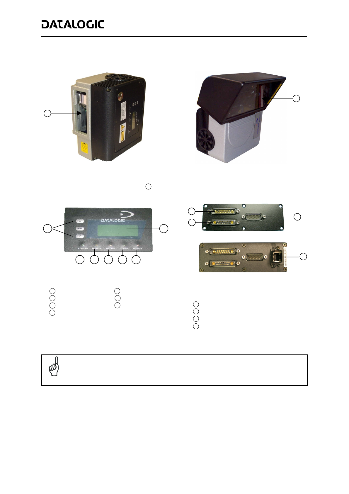
General View:
1
DS8100A QUICK GUIDE
DS8100A
1
1
Programming Keypad
1
Power On LED (Green)
2
Phase On LED (Yellow)
3
Encoder LED (Yellow)
4
Linear Model
2 3
4 5 6
Figure B
5
6
7
Laser Beam Output Windows
1
TX Data LED (Green)
Network LED (Red)
LCD Display
Figure A
7
Oscillating Mirror Model
1
2
Standard
Ethernet
Figure C
Lonworks 17-pin Male Connector
1
Lonworks 17-pin Female Connector
2
Serial Interface and I/O 26-pin male Connector
3
Harting RJ Industrial® Modular female Connector
4
3
4
NOTE
For further details on product installation, see the complete Reference Manual available on the
configuration CD-ROM included with this product.
Page 2
DS8100A QUICK GUIDE
Technical Features:
ELECTRICAL FEATURES
Supply Voltage 20 to 30 Vdc
Power Consumption 20 W typical
30 W Max. (including startup current)
Common Communication Interfaces
Model-Dependent Communication
Interfaces
Inputs
Ext. Trigger 1,
3 aux. digital inputs
Outputs
3 software programmable digital
outputs
OPTICAL FEATURES
Light Receiver Avalanche photodiode
Wavelength 630 to 680 nm
Safety Class Class 2 - EN60825-1; Class II - CDRH
Light Source Up to 4 semiconductor laser diodes
Laser Control Security system to turn laser off in case of motor slow down
READING FEATURES
Scan Rate
Max. Resolution
Max. Reading Distance
Max. Reading Width
Max. Depth of Field
USER INTERFACE
LCD Display 2 lines by 20 characters LCD
Keypad 3 keys
LED Indicators Power On (green)
Main Baud Rate
RS232
RS485 full-duplex
RS485 half-duplex
20 mA C.L.
(INT-30 with C-BOX 100 only)
Auxiliary
RS232
Other
Lonworks
Ethernet 100Mb/s
(optocoupled NPN or PNP)
(optocoupled)
≤ 1000 scans/s
(see reading diagrams on page 16)
Phase On (yellow)
Encoder (yellow)
TX Data (green)
Network (red)
1200 to 115200
19200
1200 to 115200
1.25 Mb/s
2
Page 3
X
p
DS8100A QUICK GUIDE
SOFTWARE FEATURES
Readable Codes
Code Selection Up to 10 codes during one reading phase
Headers and Terminators One header up to 128-bytes and one terminator 128-bytes
Operating Modes On Line, Serial On Line, Automatic, Test, PackTrack™, Continuous
Configuration Modes Genius™ utility program
Parameter Storage Non-volatile internal FLASH
ENVIRONMENTAL FEATURES
Operating Temperature 0° to +50 °C (+32° to +122 °F)
Storage Temperature -20° to +70 °C (-4° to +158 °F)
Humidity 90% non condensing
Ambient Light Immunity 36000 lux
Vibration Resistance:
IEC 68-2-6 test FC
2 hours on each axis
Shock Resistance:
IEC 68-2-27 test EA
3 shocks on each axis
Interleaved 2/5
Code 39 Standard
Codabar
Code 128
EAN 128
Code 93 (Standard and Full ASCII)
EAN/UPC (including Add-on 2 and Add-on 5)
Linear Models Oscillating Mirror Models
14 mm @ 2 to 10 Hz
1.5 mm @ 13 to 55 Hz
2 g @ 70 to 200 Hz
30 g; 11 ms 15 g; 11 ms
1.5 mm @ 5 to 9.1 Hz
0.5 g @ 9.1 to 150 Hz
Protection Class IP64*
PHYSICAL FEATURES
Mechanical Dimensions
Weight
* sealed connectors required, use Harting RJ Industrial® Push Pull Ethernet connector for Ethernet models.
Linear Models Oscillating Mirror Models
217 x 172.5 x 126.6 mm
(8.54 x 6.79 x 4.98 in)
5 kg (11 lbs.) 6.4 kg (14 lbs.)
275.1 x 192.3 x 254
(10.83 x 7.57 x 10 in)
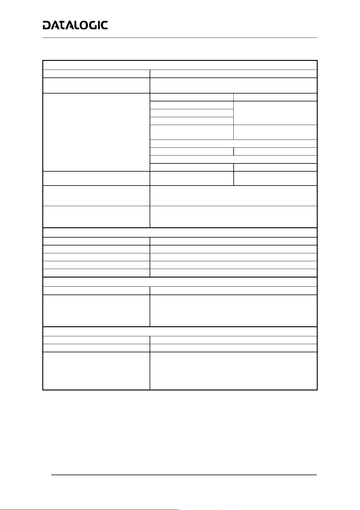
Model Description:
Laser Number:
2 = Double laser
3 = Tri
Communication Type:
0 = Standard version
1 = Ethernet version
DS8100A - X X X
le laser
Optic Version:
0 = Linear
5 = Oscillating mirror
Optical Resolution:
0 = Low resolution
1 = Medium resolution
2 = High resolution
3 = Very High resolution
3
Page 4

DS8100A QUICK GUIDE
Accessories:
NAME Description Part Number
PWR-120 J-box power unit 110/230 VAC 24 V 120 W 93ACC1530
PWR-240 J-box power unit 110/230 VAC 24 V 240 W 93ACC1070
PWR-480 J-box power unit 110/230 VAC 24 V 480 W 93ACC1080
BTK-8100 Bus terminator kit (5 pcs) 93ACC1090
BTK-8102 Double terminator kit (2 pcs) 93A051287
FBK-8100 Fast bracket kit (2 pcs) 93ACC1130
US-8100 Bracket kit (10 pcs) 93ACC1140
US-BOX C-BOX Mounting Bracket to station frame (10 pcs) 93ACC1777
PLL-8000 Optocoupled PLL device 93ACC1280
ACS-81 Air cleaning system 93ACC1430
DF-81 Dust filter (10 pcs) 93ACC1440
FS-1 Frame shaper (8 pcs) 93ACC1750
CAB-8100 10 wire shielded cable D 9.5 mm – 50 m 93ACC1120
CAB-8101 17-pin scanner/scanner connection cable 1.2 m 93A051020
CAB-8102 17-pin scanner/scanner connection cable 2.5 m 93A051030
CAB-8105 17-pin scanner/scanner connection cable 5 m 93A051040
CAB-8305 Power and bus return cable (last Slave) 5 m 93A051268
CAB-8310 Power and bus return cable (last Slave) 10 m 93A051336
CAB-8402 No power cable 2.5 m 93ACC1758
CAB-8405 No power cable 5 m 93ACC1759
CAB-6011 26-pin scanner to C-BOX 100 1 m 93A051221
CAB-6012 26-pin scanner to C-BOX 100 2 m 93A051222
CAB-6015 26-pin scanner to C-BOX 100 5 m 93A051223
CAB-6502 Fam 6K-8K cross cable 2.5 m 93A051288
CAB-6505 Fam 6K-8K cross cable 5 m 93A051289
CAB-8605 Power and Lonworks termination cable (Master) 5 m 93A051290
Sentinel-5 Supervisor (up to 5 arrays) 93A101004
Sentinel-10 Supervisor (up to 10 arrays) 93A101005
Sentinel-32 Supervisor (up to 32 arrays) 93A101007
C-BOX 100 Passive Connection Box 93ACC1510
MEP-542 Photocell kit - PNP 93ACC1727
MEP-543 Photocell kit - NPN 93ACC1728
OEK-2 Optical encoder (10 m cable + spring) 93ACC1770
OEK-1 Optical encoder kit + 10 m cable 93ACC1600
GFC-80 90° mirror 93A251020
GFC-800 90° mirror close distance 93A201103
Oscillating Mirror Models
Oscillating mirror models are used when coverage of a large reading area is required, mainly in picket fence
applications.
The oscillating mirror is placed in front of the reading aperture of the DS8100A scanner to deflect the laser beam.
As the mirror moves, this sweeping function of the laser beam allows the coverage of a larger area to locate the
barcodes.
The aperture angle is symmetrical and the scan line perpendicular to the scanner is at 0° as shown in the figure
below.
4
+25°
0°
-25°
Page 5

DS8100A QUICK GUIDE
By configuring the oscillating speed up to the maximum value of 19 Hz, raster emulation can be performed for
reading fast moving objects.
Hz Max. Aperture
0-5 50°
6-10 30°
11-15 20°
16-19 10°
By limiting the raster width to the minimum necessary, the number of scans on the reading
surface is increased.
NOTE
Electrical Connections:
The details of the connector pins are indicated in the following tables:
The DS8100A scanner provides a 26-pin male D-sub connector for connection to power supply, Host interface
(Main and Aux), and input/output signals.
26-pin D-Sub Connector Pinout
Pin Name Function
1 CHASSIS
Chassis - internally connected to GND
Cable shield connected to chassis
20 RXAUX Receive data of auxiliary RS232 (referred to GND)
21 TXAUX Transmit data of auxiliary RS232 (referred to GND)
8 OUT 1+ Configurable digital output 1 – positive pin
22 OUT 1- Configurable digital output 1 – negative pin
11 OUT 2+ Configurable digital output 2 – positive pin
12 OUT 2- Configurable digital output 2 – negative pin
16 OUT 3A Configurable digital output 3 – polarity insensitive
17 OUT 3B Configurable digital output 3 – polarity insensitive
18 EXT_TRIG/PS A External trigger (polarity insensitive) for PS
19 EXT_TRIG/PS B External trigger (polarity insensitive) for PS
6 IN2/ENC A Input signal 2 (polarity insensitive) for Encoder
10 IN2/ENC B Input signal 2 (polarity insensitive) for Encoder
14 IN3A Input signal 3 (polarity insensitive)
15 IN4A Input signal 4 (polarity insensitive)
24 IN_REF Common reference of IN3 and IN4 (polarity insensitive)
9, 13 VS Supply voltage – positive pin
23, 25, 26 GND Supply voltage – negative pin
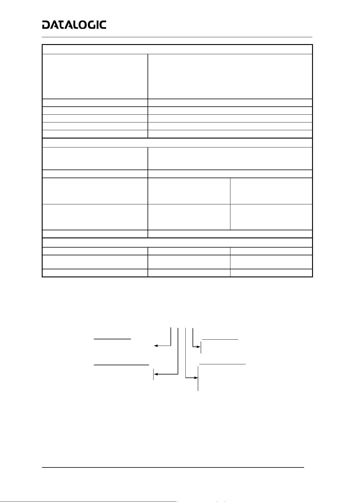
Main Interface Connector Pinout
Pin RS232 RS485 Full-Duplex RS485 Half-Duplex
2 TX TX485+ RTX485+
3 RX RX485+
4 RTS TX485- RTX485-
5 CTS RX485-
7 GND_ISO GND_ISO GND_ISO
1
10
19
26-pin male D-sub Connector
9
18
26
20 mA C.L.
(INT-30 with C-BOX 100 only)
see INT-30 instructions
5
Page 6
DS8100A QUICK GUIDE
Two 17-pin connectors provide access to the scanner’s local Lonworks network used for both input and output
connections to build a multi-sided or omni-station system.
17-pin Lonworks Connector Pinout
Pin Name
A1 GND Supply voltage (negative pin)
A2 VS Supply voltage 20 to 30 Vdc (positive pin)
1 CHASSIS
2 n.c. Not connected
3 CHASSIS
4 n.c. Not connected
5 n.c. Not connected
6 n.c. Not connected
7 VS_I/O Supply voltage of I/O circuit
8 Lon A+ Lonworks a line (positive pin)
9 Lon A- Lonworks a line (negative pin)
10 Lon B+ Lonworks b line (positive pin)
11 Lon B- Lonworks b line (negative pin)
12 SYS_I/O System signal
13 SYS_ENC_I/O System signal
14 Reserved Internally connected
15 Ref_I/O Reference voltage of I/O circuit
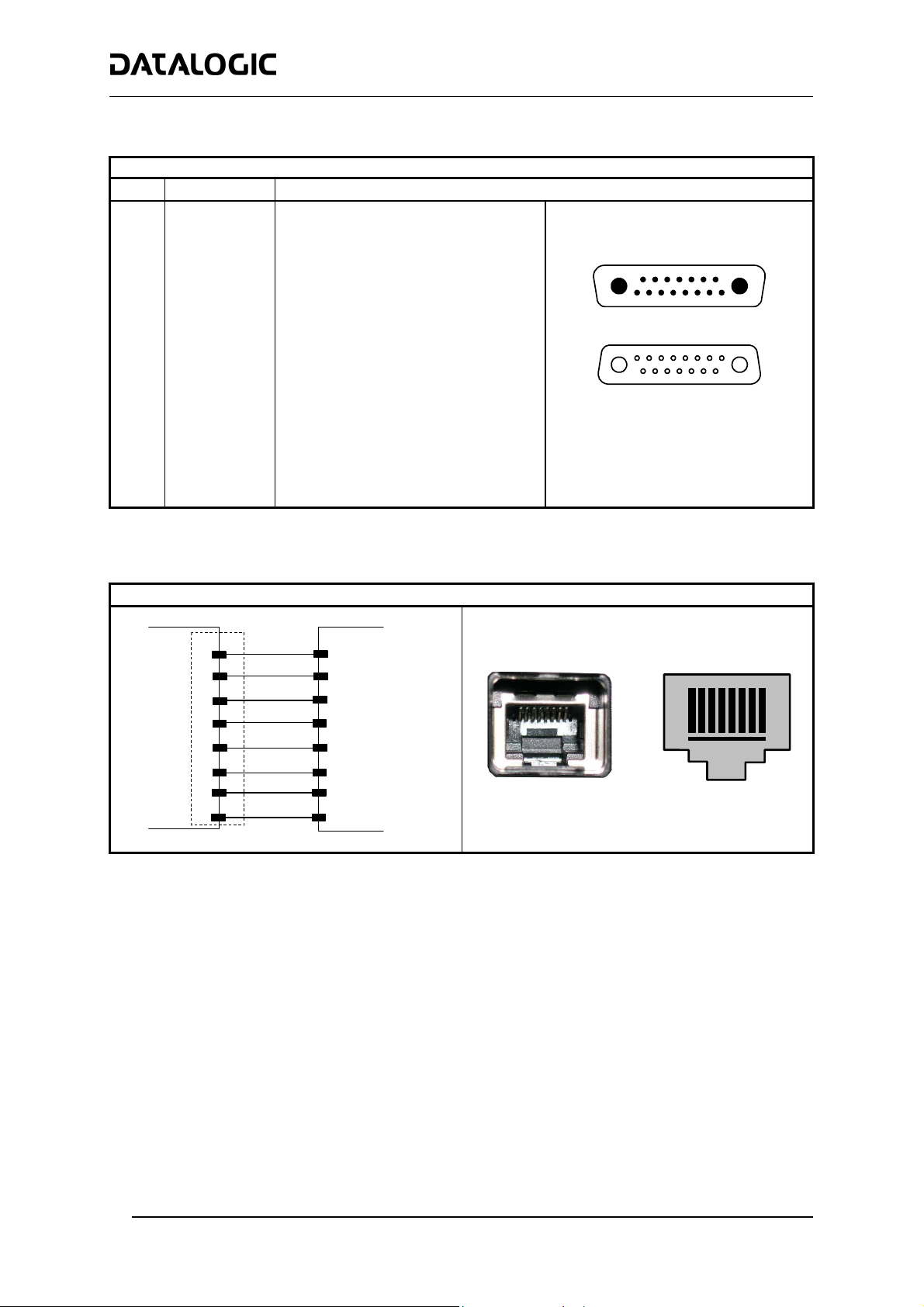
Ethernet Version
An Ethernet connector is used for connection to the remote Host (for ex. Remote PC connected via Internet).
Function
Cable shield A - internally connected by
capacitor to chassis
Cable shield B - internally connected by
capacitor to chassis
1
A1
Male - Input
15
A1
1
Female - Output
17-pin Local Lonworks Connectors
A2
15
A2
DS8100A
n. c. = not connected
TX+
TX-
RX+
n. c.
n. c.
RX-
n. c.
n. c.
Harting RJ Industrial® Modular Connector
HUB / SWITCH
1
2
3
4
5
6
7
8
1
2
3
4
5
6
7
8
Harting RJ Industrial Female Connector
1
8
6
Page 7
DS8100A QUICK GUIDE
Network Termination:
When building a Lonworks system the network must be properly terminated by positioning the BTK-8102
Lonworks terminator in the DS8100A master reader and the BTK-8100 Lonworks bus return in the last DS8100A
slave reader.
The BTK-8100 bus return provides a connector to be inserted in the Lonworks 17-pin female connector of the last
slave reader in the network; while the BTK-8102 Lonworks terminator provides a different connector to be
inserted in the Lonworks 17-pin male connector of the master reader:
DS8100A Master
DS8100A Last Slave
BTK-8102
CAB-810X
BTK-8102 and BTK-8100
Two cables are also provided as accessories to terminate and power the network: CAB-8605 and CAB-8305.
CAB-8605 is a power and Lonworks termination cable to be used for connecting the DS8100A master to an
external power unit within the network; while CAB-8305 is a power and bus return cable to be used for connecting
the last DS8100A slave to an external power unit.
DS8100A Master
Network
DS8100A Last Slave
Network
Power Unit
BTK-8100
CAB-810X
CAB-8605
CAB-8605 and CAB-8305
CAB-8305
7
Page 8

DS8100A QUICK GUIDE
Connectivity:
Examples of the most common system layouts are shown in this section, for additional layouts refer to the
Reference Manual.
Point-to-Point Layout
Standard
CAB601X
Presence
Sensor*
PWR-120
C-BOX 100
Local Host
* P.S. (Presence Sensor) connected to External Trigger/PS input.
Point-to-Point for Standard Models
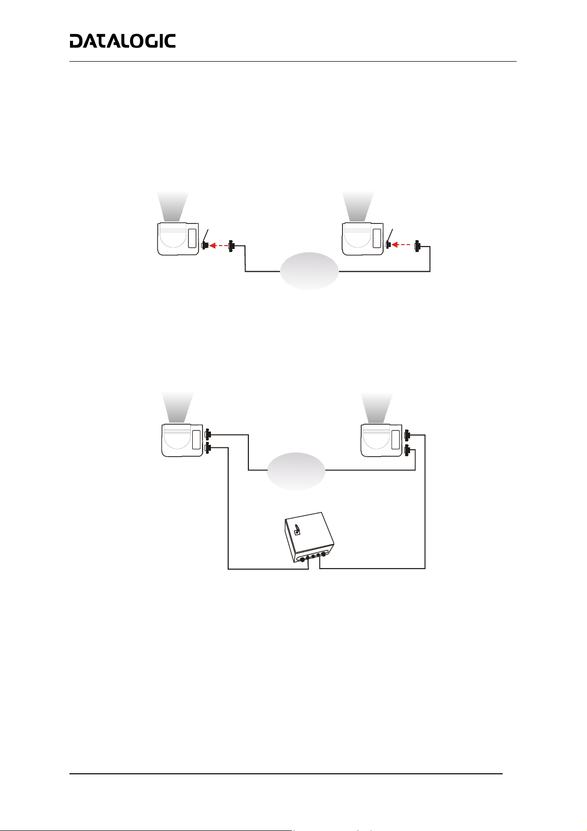
Pass Through Layout
Standard
CAB601X
P.S.*
C-BOX 100
MAIN
AUX.
1
2
P.S.* P.S.*
C-BOX 100
Local Host
DS4600A
Gryphon
DS4600A
C-BOX 100
1 21
PWR-120
* P.S. (Presence Sensor) connected to External Trigger/PS input.
Pass Through Connection for DS8100A Standard Models
8
Page 9

P.S.*
P.S.*
DS8100A QUICK GUIDE
Multiplexer Layout
P.S.*
DS8100A
C-BOX 100
1
RS485 HD Main Interface
C-BOX 100
DS4600A
C-BOX 100
#1 #31
* P.S. (Presence Sensor) connected to External Trigger/PS input.
Multiplexer for DS8100A Standard Models
#0
DS4600A
Local Host
PWR-120
MX4000
1
9
Page 10

r
r
DS8100A QUICK GUIDE
Local Lonworks Networks
CAB810X
Slave 1
Maste
CAB830X
CAB601X
BTK-8102
PWR-120
C-BOX 100**
P.S.*
Local Host
* P.S. (Presence Sensor) connected to External Trigger/PS input.
** C-BOX 100 modified to accept scanner power
Small Synchronized Network with 2 Readers
CAB810X
Slave 2
CAB810X
CAB810X CAB830X
Slave 3
Slave 1
Slave 4
Maste
CAB810X
CAB601X
PWR-240
CAB860X
C-BOX 100**
P.S.*
Encoder***
Local Host
* P.S. (Presence Sensor) connected to External Trigger/PS input.
** C-BOX 100 modified to accept scanner power.
*** Encoder connected to IN2/ENC input.
Small Synchronized Network with more than 2 Readers and Single Power Unit
10
Page 11

Host
HUB
DS8100A QUICK GUIDE
Local Lonworks Networks
ETHERNET
SC6000
CAB-SC6003
Extended I/O
CAB-810x
CAB-810x
CAB-810x
DX8200A
DS8100A
Large Synchronized Network with DX8200A and DS8100A Scanners
DX8200A
CAB-810x
up to 4
scanners per
branch
AUX
DS8100A
CAB-SC6103
Cable
Power/Net
CAB-SC6003
LONWORKS
CAB-810x
up to 3
scanners
per
branch
BTK8100
Bus Return
DX8200A
CAB-810X
VAC INPUT
DS8100A
PWO
ENCODER
PS
PS Aux
BTK8100
Bus Return
CAB-810x
DS8100A
SC6000
Conveyor
Large Synchronized Network Reading Station
11
Page 12

DS8100A QUICK GUIDE
C-BOX 100 Pinout for DS8100A:
The table below gives the pinout of the C-BOX 100 terminal block connectors. Use this pinout when the DS8100A
reader is connected in a network by means of the C-BOX 100:
C-BOX 100 Terminal Block Connectors
Power
1, 3, 5 VS
2, 4, 6 GND
7, 8 EARTH GROUND
20, 40 Reserved
Inputs
27 EXT TRIG/PS A (polarity insensitive) for PS
28 EXT TRIG/PS B (polarity insensitive) for PS
29 IN 2/ENC A (polarity insensitive) for Encoder
30 IN 2/ENC B (polarity insensitive) for Encoder
31, 33 IN 3A (polarity insensitive)
32, 34 IN 4A (polarity insensitive)
36 IN 3B/IN 4B Reference (polarity insensitive)
Outputs
21 OUT 1+
22 OUT 1-
23 OUT 2+
24 OUT 2-
25 OUT 3A (polarity insensitive)
26 OUT 3B (polarity insensitive)
Auxiliary Interface
35 TX AUX
37 RX AUX
38, 39 GND
Main Interface
RS232 RS485 Full-Duplex RS485 Half-Duplex
11, 15 TX 232 TX 485+ RTX 485+
12, 16 RTS 232 TX 485- RTX 485-
17 RX 232 RX 485+
18 CTS 232 RX 485-
10, 14, 19 SGND Main Isolated SGND Main Isolated SGND Main Isolated
9, 13 RS485 Cable Shield RS485 Cable Shield
20 mA C.L.
(with INT-30 only)
see INT-30
instructions
12
Page 13

DS8100A QUICK GUIDE
Mechanical Installation:
DS8100A can be installed to operate in any position. There are 16 screw holes (M6 X 8) on the sides of the
scanner for mounting. The diagram below can be used for installation; refer to the Reading Diagrams for correct
positioning of the scanner with respect to the reading zone and scanner orientation.
126.6
[4.98]
4
5
°
.
7
8
4
]
217
[8.54]
172.5
[6.79]
M6 N°16
67.5
[2.66]
50
[1.97]
4
6
[
1
.
4
5
67.5
[2.66]
°
mm
46.8
[1.84]
50
[1.97]
DS8100A Linear Model Overall Dimensions
inch
192.3
[7.57]
4
4
6
.
7
275.1
[10.83]
254
[10.00]
67.5
[2.66]
50
[1.97]
5
°
]
.
8
[
4
1
4
5
67.5
[2.66]
46.8
[1.84]
50
[1.97]
DS8100A Oscillating Mirror Model Overall Dimensions
°
mm
inch
°
8
2
13
Page 14

DS8100A QUICK GUIDE
R 15
0.59
164
6.45
5
0.19
164
6.45
R 15 N°4
0.59
80
3.15
100
3.93
ST-163 Mounting Bracket Overall Dimensions
100
30
16
0.63481.88
45
1.77
17.5
0.68
15
0.59
3.93
1.18
8.5 N° 4
0.33
mm
inch
When installing several scanners, take care to position them correctly so that no laser beam
enters the reading window perpendicularly and at the same level of the output beam of the
other scanners. This condition could occur more frequently for side mounted applications. If
these precautions are not followed, it may occur that the laser of the blinded scanner starts
WARNING
blinking due to an internal circuit which temporarily turns the laser off when detecting a power
anomaly. To resolve this problem, it is sufficient to slightly change the inclination and position
of one of the two scanners involved.
Reading Conditions:
• ANSI Grade B minimum
• 1000 scans/sec
The following tables describe the requirements for standard applications.
Minimum Code Height for ACR Reading (mm)
45° 30°
Conveyor Speed (m/s) 0.5 1 1.5 2 2.5 3 0.5 1 1.5 2 2.5 3
0.25
0.30
2/5 Interleaved
Code Resolution (mm)
0.33
0.38
0.50
0.72
1.00
Ratio 3:1
Minimum Code Height for ACR Reading (mm)
45° 30°
Conveyor Speed (m/s) 0.5 1 1.5 2 2.5 3 0.5 1 1.5 2 2.5 3
0.25
0.30
Code 39
Code Resolution (mm)
0.33
0.38
0.50
0.72
1.00
Ratio 3:1; Interdigit = Module Size
10 11 13 14 16 17 7 8 9 10 12 13
12 13 14 16 17 19 8 9 10 11 12 14
12 14 15 17 18 20 8 9 10 12 13 14
14 15 16 18 19 21 9 10 11 12 14 15
18 18 20 21 23 24 11 12 13 14 15 17
24 25 26 27 28 30 15 16 16 18 19 20
33 33 34 35 36 37 20 20 21 22 23 24
Table 1
9 9 11 12 14 15 6 7 8 9 10 11
10 11 12 13 15 16 7 7 8 10 11 12
11 11 12 14 15 17 7 8 9 10 11 12
12 13 13 15 16 18 8 8 9 10 12 13
15 16 16 17 18 20 9 10 11 12 13 14
20 21 22 22 23 24 13 13 14 14 15 16
27 28 29 29 30 31 17 17 18 18 19 20
Table 2
14
Page 15

DS8100A QUICK GUIDE
Minimum Code Height for ACR Reading (mm)
45° 30°
Conveyor Speed (m/s) 0.5 1 1.5 2 2.5 3 0.5 1 1.5 2 2.5 3
0.25
0.30
Code 128 – Ean 128
Code Resolution (mm)
0.33
0.38
0.50
0.72
1.00
Minimum Code Height for ACR Reading (mm)
45° 30°
Conveyor Speed (m/s) 0.5 1 1.5 2 2.5 3 0.5 1 1.5 2 2.5 3
0.25
0.30
Codabar
Code Resolution (mm)
0.33
0.38
0.50
0.72
1.00
Ratio 3:1; Interdigit = Module Size
Minimum Code Height for ACR Reading (mm)
45° 30°
Conveyor Speed (m/s) 0.5 1 1.5 2 2.5 3 0.5 1 1.5 2 2.5 3
0.25
0.30
EAN 8-13, UPC-A
Code Resolution (mm)
0.33
0.38
0.50
0.72
1.00
7 9 10 12 13 15 6 6 8 9 10 11
8 9 11 12 14 15 6 7 8 9 10 12
9 10 11 13 14 16 6 7 8 9 11 12
10 11 12 14 15 17 6 8 9 10 11 12
12 13 14 16 17 19 8 9 10 11 12 13
16 17 18 19 21 22 10 11 12 13 14 15
21 22 23 24 25 26 13 14 15 16 17 18
Table 3
8 9 10 12 13 15 5 6 8 9 10 11
9 9 11 12 14 15 6 7 8 9 10 12
9 10 11 13 14 16 6 7 8 9 11 12
10 11 12 14 15 17 7 8 9 10 11 12
13 13 14 16 17 19 8 9 10 11 12 13
17 18 18 19 21 22 11 11 12 13 14 15
23 23 24 25 26 26 14 15 15 16 17 18
Table 4
7 8 9 11 12 14 5 6 7 8 9 11
8 9 10 11 13 14 6 6 7 9 10 11
9 10 10 12 13 15 6 7 8 9 10 11
10 11 11 12 14 15 6 7 8 9 10 12
12 13 14 14 15 17 8 8 9 10 11 12
16 17 18 18 19 20 10 11 11 12 13 14
21 22 23 24 24 25 13 14 15 15 16 16
Table 5
15
Page 16

Reading Diagrams:
Note: 0,0 corresponds to the center of the laser beam output window.
DS8100A QUICK GUIDE
CONDITIONS
Code = Interleaved 2/5 or Code 39
PCS = 0.90
“Pitch“ angle = 0°
“Skew“ angle = 10°
“Tilt“ angle = 0°
CONDITIONS
Code = Interleaved 2/5 or Code 39
PCS = 0.90
“Pitch“ angle = 0°
“Skew“ angle = 10°
“Tilt“ angle = 0°
DS8100A-2X10 – 0.50 mm/20 mils
-12
-16
-20
-24
-28
(in)
024 40
0
28
70
24
60
20
50
16
40
12
30
8
20
4
10
0
0
-10
-4
-20
-8
-30
-40
-50
-60
-700
(cm)
60
32 48
80
DS8100A-2X10 – 0.38 mm/15 mils
-12
-16
-20
-24
-28
(in)
024 40
0
28
70
24
60
20
50
16
40
12
30
8
20
4
10
0
0
-10
-4
-20
-8
-30
-40
-50
-60
-700
(cm)
60
32 48
80
100
100
56 64
120 140 160
56 64
120 140 160
68
180
180
(in)
(cm)
(in)
68
(cm)
16
Page 17

CONDITIONS
Code = Interleaved 2/5 or Code 39
PCS = 0.90
“Pitch“ angle = 0°
“Skew“ angle = 10°
“Tilt“ angle = 0°
CONDITIONS
Code = Interleaved 2/5 or Code 39
PCS = 0.90
“Pitch“ angle = 0°
“Skew“ angle = 10°
“Tilt“ angle = 0°
DS8100A-3X00 – 0.50 mm/20 mils
-12
-16
-20
-24
-28
(in)
024 40
60
0
28
70
24
60
20
50
16
40
12
30
8
20
4
10
0
0
-10
-4
-20
-8
-30
-40
-50
-60
-700
(cm)
32 48
80
DS8100A-3X10 – 0.38 mm/15 mils
2416
60
-12
-16
-20
-24
-28
(in)
0
0
40
28
70
24
60
20
50
16
40
12
30
8
20
4
10
0
0
-10
-4
-20
-8
-30
-40
-50
-60
-70
(cm)
DS8100A QUICK GUIDE
100
80
120 140 160
32 48
40
100 120 140 160
56 64
56 64
68
180
(in)
(cm)
(in)
(cm)
17
Page 18

CONDITIONS
Code = Interleaved 2/5 or Code 39
PCS = 0.90
“Pitch“ angle = 0°
“Skew“ angle = 10°
“Tilt“ angle = 0°
DS8100A-3X20 – 0.30 mm/12 mils
24
20
16
12
8
4
0
-4
-8
-12
-16
-20
-24
(in)
0
0
60
50
40
30
20
10
0
-10
-20
-30
-40
-50
-60
(cm)
24
60
DS8100A-3X30 – 0.25 mm/10 mils
50
40
0
0
40
20
16
DS8100A QUICK GUIDE
32 48
80
40
100 120 140 160
2416
60
32 48
80
56 64
40
100
120
(in)
(cm)
(in)
(cm)
CONDITIONS
Code = Interleaved 2/5 or Code 39
PCS = 0.90
“Pitch“ angle = 0°
“Skew“ angle = 10°
“Tilt“ angle = 0°
0
-4
-8
-12
-16
-20
12
4
(in)
30
8
20
10
0
-10
-20
-30
-40
-50
(cm)
18
Page 19

CONDITIONS
Code = Interleaved 2/5 or Code 39
PCS = 0.90
“Pitch“ angle = 0°
“Skew“ angle = 10°
“Tilt“ angle = 0°
CONDITIONS
Code = Interleaved 2/5 or Code 39
PCS = 0.90
“Pitch“ angle = 0°
“Skew“ angle = 10°
“Tilt“ angle = 0°
DS8100A-3X05 – 0.50 mm/20 mils
-12
-16
-20
-24
-28
(in)
024 40
60
0
28
70
24
60
20
50
16
40
12
30
8
20
4
10
0
0
-10
-4
-20
-8
-30
-40
-50
-60
-700
(cm)
32 48
80
DS8100A-3X15 – 0.38 mm/15 mils
2416
60
-12
-16
-20
-24
-28
(in)
0
0
40
28
70
24
60
20
50
16
40
12
30
8
20
4
10
0
0
-10
-4
-20
-8
-30
-40
-50
-60
-70
(cm)
DS8100A QUICK GUIDE
120 140 160
100
32 48
80
40
100 120 140 160
56 64
56 64
68
180
(in)
(cm)
(in)
(cm)
19
Page 20

CONDITIONS
Code = Interleaved 2/5 or Code 39
PCS = 0.90
“Pitch“ angle = 0°
“Skew“ angle = 10°
“Tilt“ angle = 0°
DS8100A-3X25 – 0.30 mm/12 mils
0
0
16
40 60
24
60
20
50
16
40
12
30
8
20
4
10
0
0
-10
-4
-20
-8
-30
-12
-40
-16
-50
-20
-60
-24
(cm)
(in)
DS8100A-3X35 – 0.25 mm/10 mils
50
40
0
0
40
20
16
24 40
32
80 100 120 140
2416
60
32 48
80
DS8100A QUICK GUIDE
120
(in)
(cm)
(in)
(cm)
48 56
40
100
CONDITIONS
Code = Interleaved 2/5 or Code 39
PCS = 0.90
“Pitch“ angle = 0°
“Skew“ angle = 10°
“Tilt“ angle = 0°
0
-4
-8
-12
-16
-20
12
4
(in)
30
8
20
10
0
-10
-20
-30
-40
-50
(cm)
20
Page 21

DS8100A QUICK GUIDE
User Interface:
How To Build A Simple Interface Test Cable:
The following wiring diagram shows a simple test cable including power, external (push-button) trigger and PC
RS232 COM port connections.
DS8100A
Compliance:
Laser Safety
26-pin D-sub female
21
20
23
13
25
9
18
19
Trigger
TXAUX
RXAUX
GND
VS
GND
VS
EXT TRIG A
EXT TRIG B
9-pin D-sub female
Power Supply
VS (20 – 30 VDC)
Power GND
2
RX
PC
3
TX
5
GND
1
3
2
1
Laser Safety Label
1
Warning and Device Class Label
2
Figure A
Identification Label
3
Figure B
Laser Safety Label
1
The scanner is classified as a Class 2 laser product according to EN60825-1 regulations and as a Class II laser
product according to CDRH regulations.
Disconnect the power supply when opening the device during maintenance or installation to avoid exposure to
hazardous laser light.
There is a safety device which allows the laser to be switched on only if the motor is rotating above the threshold
for its correct scanning speed.
The laser beam can be switched off through a software command (see also the Genius™ Help On-Line).
21
Page 22

DS8100A QUICK GUIDE
AVOID EXPOSURE
LASER LIGHT IS EMITTED
FROM THIS APERTURE
CAUTION-CLASS 3B
LASER LIGHT
WHEN OPEN
AVOID
EXPOSURE TO BEAM
AVOID EXPOSURE
LASER RADIATION IS EMITTED FROM THIS APERTURE
Laser Safety Label for Standard and Oscillating Mirror Models
LASER LIGHT
DO NOT STARE INT O BEAM
CLASS 2 LASER PRODUCT
MAXIMUM OUTPUT RADIATION 1 mW
EMITTED WAVELENGTH 630~680 nm
TO EN 60825-1:2001
Warning and Device Class Label Device Identification Label
DATALOGIC S.P.A. Via Candini, 2
40012 Calderara di Reno - Bologna - Ital y
Manufactured Volt
Model No. Amp.
Serial N o.
This product conforms to the applicable requirements
of 21CFR1040 at the date of manufacture.
The laser diodes used in this device are classified as Class 3B laser products according to EN 60825-1 regulations
and as Class IIIb laser products according to CDRH regulations. As it is not possible to apply a classification label
on the laser diodes used in this device, the following label is reproduced here:
LASER LIGHT
AVOID EXPOSURE TO BEAM
CLASS 3B LASER PRODUCT
MAXIMUM OUTPUT RADIATION 30 mW
EMITTED WAVELENGTH 630~680 nm
TO EN 60825-1 (2001)
Laser Diode Class Label
Any violation of the optic parts in particular can cause radiation up to the maximum level of the laser diode
(30 mW at 630~680 nm).
Power Supply
- This product is intended to be installed by Qualified Personnel only.
- This scanner is intended to be supplied by either a UL Listed power supply marked 'Class 2' or 'LPS', output
rated 20 - 30 V dc , minimum 1.5 A or by a UL Listed computer with LPS outputs.
- This scanner must be supplied by a Class II Power Supply Unit conforming to the EN 60950 safety
regulation.
WEEE Compliance
22
Page 23

dichiara che
declares that the
déclare que le
bescheinigt, daß das Gerät
declare que el
DS8100A-XXXX, Laser Scanner
e tutti i suoi modelli
and all its models
et tous ses modèles
und seine Modelle
y todos sus modelos
sono conformi alle Direttive del Consiglio Europeo sottoelencate:
are in conformity with the requirements of the European Council Directives listed below:
sont conformes aux spécifications des Directives de l'Union Européenne ci-dessous:
den nachstehenden angeführten Direktiven des Europäischen Rats:
cumple con los requisitos de las Directivas del Consejo Europeo, según la lista siguiente:
89/336/EEC EMC Directive e 92/31/EEC, 93/68/EEC emendamenti successivi
and further amendments
et ses successifs amendements
und späteren Abänderungen
y succesivas enmiendas
73/23/EEC Low Voltage Directive
Basate sulle legislazioni degli Stati membri in relazione alla compatibilità elettromagnetica ed alla sicurezza dei prodotti.
On the approximation of the laws of Member States relating to electromagnetic compatibility and product safety.
Basée sur la législation des Etats membres relative à la compatibilité électromagnétique et à la sécurité des produits.
Über die Annäherung der Gesetze der Mitgliedsstaaten in bezug auf elektromagnetische Verträglichkeit und Produktsicherheit
entsprechen.
Basado en la aproximación de las leyes de los Países Miembros respecto a la compatibilidad electromagnética y las Medidas
de seguridad relativas al producto.
Questa dichiarazione è basata sulla conformità dei prodotti alle norme seguenti:
This declaration is based upon compliance of the products to the following standards:
Cette déclaration repose sur la conformité des produits aux normes suivantes:
Diese Erklärung basiert darauf, daß das Produkt den folgenden Normen entspricht:
Esta declaración se basa en el cumplimiento de los productos con las siguientes normas:
EN 55022 (Class A ITE), August 1994:
Amendment A1 (Class A ITE), October 2000:
EN 61000-6-2, October 2001: ELECTROMAGNETIC COMPATIBILITY (EMC)
EN 60950-1, December 2001: INFORMATION TECHNOLOGY EQUIPMENT - SAFETY –
EN 60825-1, June 1994:
Amendments A11 (1996), A2 (2001)
Lippo di Calderara, 29/11/2005
Ruggero Cacioppo
DATALOGIC S.p.A.,
Via Candini, 2
40012 - Lippo di Calderara
Bologna - Italy
LIMITS AND METHODS OF MEASUREMENTS OF RADIO DISTURBANCE
CHARACTERISTICS OF INFORMATION TECHNOLOGY EQUIPMENT
P
ART 6-2: GENERIC STANDARDS - IMMUNITY FOR INDUSTRIAL ENVIRONMENTS
P
ART 1: GENERAL REQUIREMENTS
SAFETY OF LASER PRODUCTS –
P
ART 1: EQUIPMENT CLASSIFICATION, REQUIREMENTS AND USER’S GUIDE
Quality Assurance Laboratory Manager
821001102 (Rev. C)
05
 Loading...