

Page 1

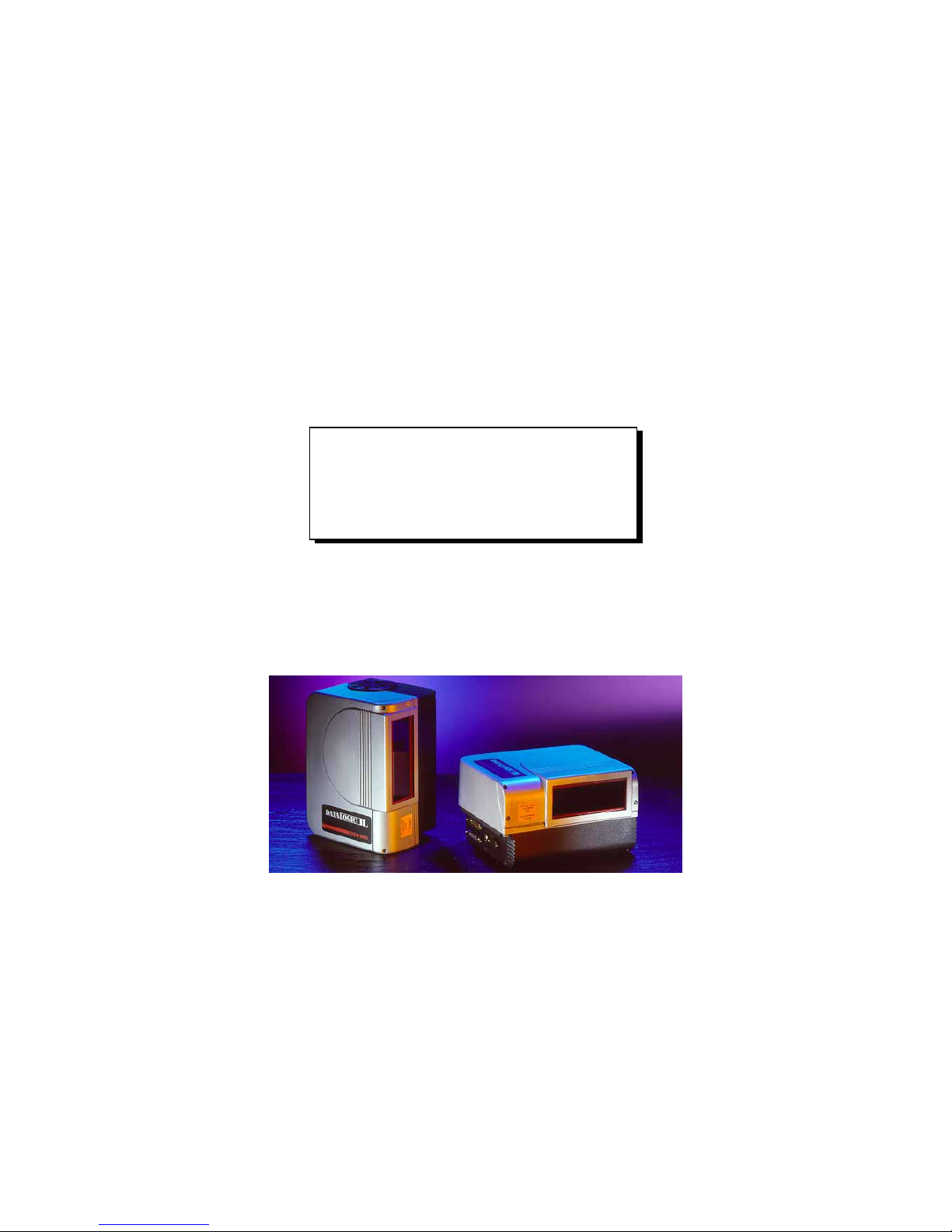
DS8100
Installation Manual
Page 2
DS8100
INSTALLATION MANUAL
Page 3

We
DATALOGIC S.p.A.
Via Candini, 2
40012 - Lippo di Calderara
Bologna - Italy
declare under our sole responsibility that the product
DS8100-XXXX, Laser Scanner and all its models
to which this declaration relates is in c onform ity with the f ollowing standards or other normat ive
documents
EN 55022, August 1994
:L
IMITS AND METHODS OF MEASUREMENTS OF RADIO DISTURBANCE
CHARACTERISTICS OF INFORMATION TECHNOLOGY EQUIPMENT
(ITE)
EN 50082-2, March 1995
:E
LECTROMAGNETIC COMPATIBILITY
. G
ENERIC IMMUNITY STANDARD
.
P
ART
2: I
NDUSTRIAL ENVIRONMENT
EN 60950, October 1996
:S
AFETY OF INFORMATION TECHNOLOGY EQUIPMENT, INCLUDING
ELECTRICAL BUSINESS EQUIPMENT
EN 60825, March 1993
:R
ADIATION SAFETY OF LASER PRODUCTS, EQUIPMENT
CLASSIFICATION
,
REQUIREMENTS AND USER’S GUIDE
Following the provision of the Directive(s):
89/336 CEE
AND SUCCESSIVE AMENDMENTS
, 92/31 CEE; 93/68 CEE; 73/23 CEE
Ruggero Cacioppo
Lippo di Calderara, 23.03.1998
Quality Assurance Supervi sor
Product names mentioned herein are for i dentification purposes only and m ay be trademarks
and or registered trademarks of t hei r respective companies.
Datalogic reserves the right t o make modificati ons and improvements without pri or not i fication.
© 1998 Datalogic S.p.A.
821000163 (Rev. C)
Page 4

iii
CONTENTS
General view .......................................................................................v
SAFETY PRECAUTIONS
................................................................ vii
Electrical Safety................................................................................ vii
Laser Safety...................................................................................... vii
Standard Regulations....................................................................... vii
Power Supply.....................................................................................ix
1. GENERAL FEATURES
...................................................................1.1
1.1 Introduction.......................................................................................1.1
1.2 Description .......................................................................................1.3
1.2.1 Indicators - DS8100 Serial Interface ................................................1.4
1.2.2 Indicators - DS8100 Bus Interface ...................................................1.4
1.3 Available Models..............................................................................1.5
1.4 Accessories......................................................................................1.5
1.5 Applications......................................................................................1.6
2. INSTALLATION - DS8100 SERIAL INTERFACE
...........................2.1
2.1 Package Contents ...........................................................................2.1
2.2 Guide To Installation........................................................................2.2
2.3 Opening The Scanner......................................................................2.3
2.3.1 Main Interface Selection..................................................................2.4
2.3.2 Multidrop Address Selection............................................................2.5
2.4 Mechanical Installation ....................................................................2.6
2.5 Electrical Connections.....................................................................2.7
2.5.1 DS8100 Connectors ........................................................................2.7
2.5.2 Power Supply.................................................................................2.10
2.5.3 Main Serial Interface......................................................................2.10
RS232 Interface.............................................................................2.11
RS485 Full-Duplex Interface..........................................................2.12
RS485 Half-Duplex Interface.........................................................2.13
20 mA Current Loop Interface .......................................................2.15
2.5.4 Auxiliary Interface..........................................................................2.16
RS232 Auxiliary Interface ..............................................................2.16
RS485 Half-Duplex Auxiliary Interface ..........................................2.17
2.5.5 Inputs.............................................................................................2.17
2.5.6 Outputs..........................................................................................2.21
2.6 Positioning.....................................................................................2.22
Page 5

iv
2.7 Typical Layouts..............................................................................2.24
2.7.1 Standard (Point-to-Point)...............................................................2.24
2.7.2 Pass Through ................................................................................2.25
2.7.3 RS485 Master/Slave......................................................................2.26
2.7.4 Multiplexer .....................................................................................2.27
2.7.5 Omnidirectional Reading ...............................................................2.28
3. INSTALLATION — DS8100 BUS INTERFACE
..............................3.1
3.1 Package Contents ...........................................................................3.1
3.2 Guide To Installation........................................................................3.2
3.3 Mechanical Installation ....................................................................3.3
3.4 Electrical Connections.....................................................................3.4
3.4.1 Power Supply...................................................................................3.5
3.4.2 Inputs...............................................................................................3.6
3.5 Positioning.......................................................................................3.7
3.6 Typical Layout..................................................................................3.8
4.
READING FEATURES
....................................................................4.1
4.1 Code Reconstruction.......................................................................4.1
4.1.1 The Tilt Angle For Code Reconstruction .........................................4.1
4.2 Performance....................................................................................4.2
4.3 Reading Diagrams...........................................................................4.3
5. MAINTENANCE
..............................................................................5.1
5.1 Cleaning...........................................................................................5.1
6. TECHNICAL FEATURES
................................................................6.1
Page 6
v
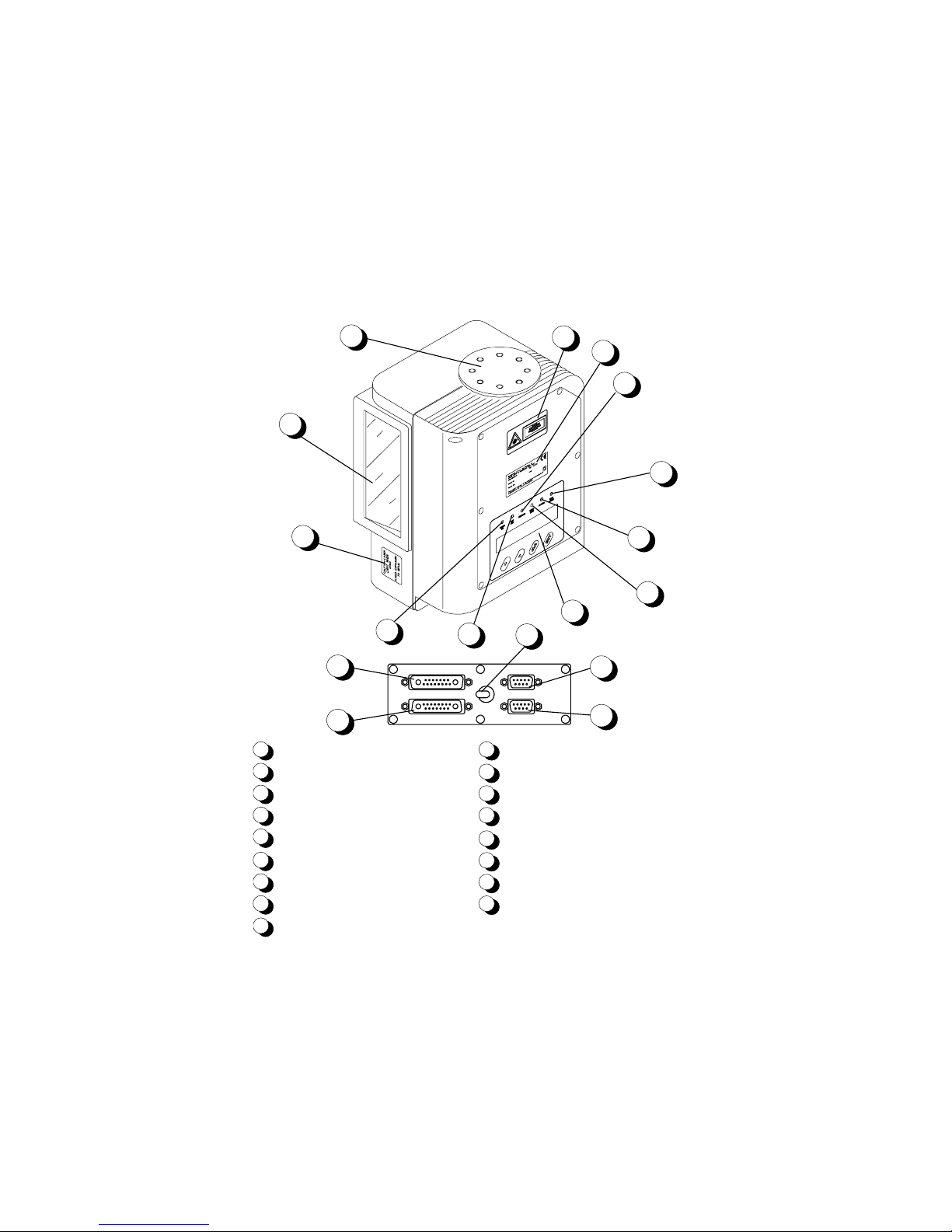
DS8100
General View
Laser Beam Output Window
Laser Safety Label
Power ON LED
Ext Trig LED
Keypad and Display
Good Read LED
TX Data LED
User Signal LED
1
2
3
4
5
6
7
8
9
Encoder LED
Warning and Device Class Label
Mounting Holes
15
11
12
13
14
16
17
10
Product Label
Main Interface Connector
Aux. Interface/Input Signal Connector A
Aux. Interface/Input Signal Connector B
Output Signal Connector
Laser Beam and Motor Power Switch
9
6
3
4
7
8
2
11
1
5
10
12
14
16
13
15
17
Figure A - DS8100 Serial Interface version
Page 7
vi
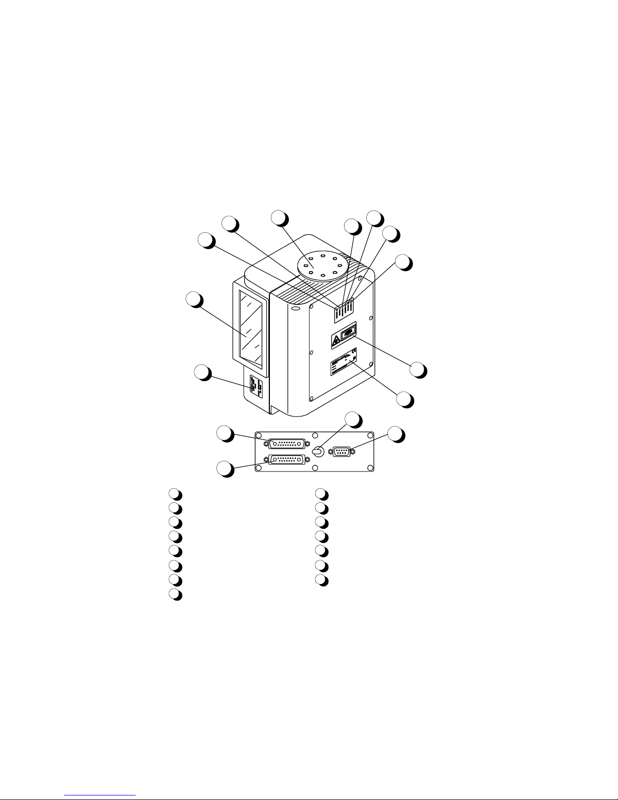
DS8100
General View
7
6
8
2
11
1
5
10
9
3
4
Laser Beam Output Window
Laser Safety Label
Product Label
Warning and Device Class Label
Power ON LED
Ext Trig LED
Encoder LED
Good Read LED
1
2
3
4
5
6
7
8
9
Mounting Holes
Network LED
11
Lonworks Input Connector
12
10
TX Data LED
15
13
Lonworks Output Connector
14
RS232 Debug Connector
13
14
12
15
Laser Beam and Motor Power Switch
Figure B - DS8100 Bus Interface version
Page 8

vii
SAFETY PRECAUTIONS
ELECTRICAL SAFETY
This product conforms to the applicable requirements contained in
the European Standard for electrical safety EN-60950 at the date of
manufacture.
!
This symbol refers to operations that must be performed by
qualified personnel only.
Example: opening the device.
This symbol refers to operations where there is danger of
electrical shock.
Before opening the device make s ure the power
cable is disconnected to avoid electric shock.
LASER SAFETY
The following information is provided to comply with the rules imposed by
international authorities and refers to the correct use of the DS8100 scanner.
Standard Regulations
This scanner utilizes up to 4 low-power laser diodes. Although s tar ing dir ec tly
at the laser beam mom entarily causes no known biological dam age, avoid
staring at the beam as one would with any very strong light source, suc h as
the sun. Avoid that the laser beam hits the eye of an observer, even through
reflective surfaces such as mirrors, etc.
This product conforms to the applicable requirements of both IEC 825-1 and
CDRH 21 CFR 1040 at the date of manufacture. The s c anner is classified as
a Class 2 laser product according to IEC 825-1 regulations and as a Clas s II
laser product according to CDRH regulations.
There is a safety device wich allows the laser to be switched on only if the
motor is rotating above the threshold for its correct scanning speed.
Page 9
viii
WARNING
Use of controls or adjustments or performance of
procedures other than those specified her ein may result
in exposure to dangerous laser radiation.
The laser light is visible to the human eye and is em itted from the window on
the side of the reader (Figure A,
1
and Figure B, 1).
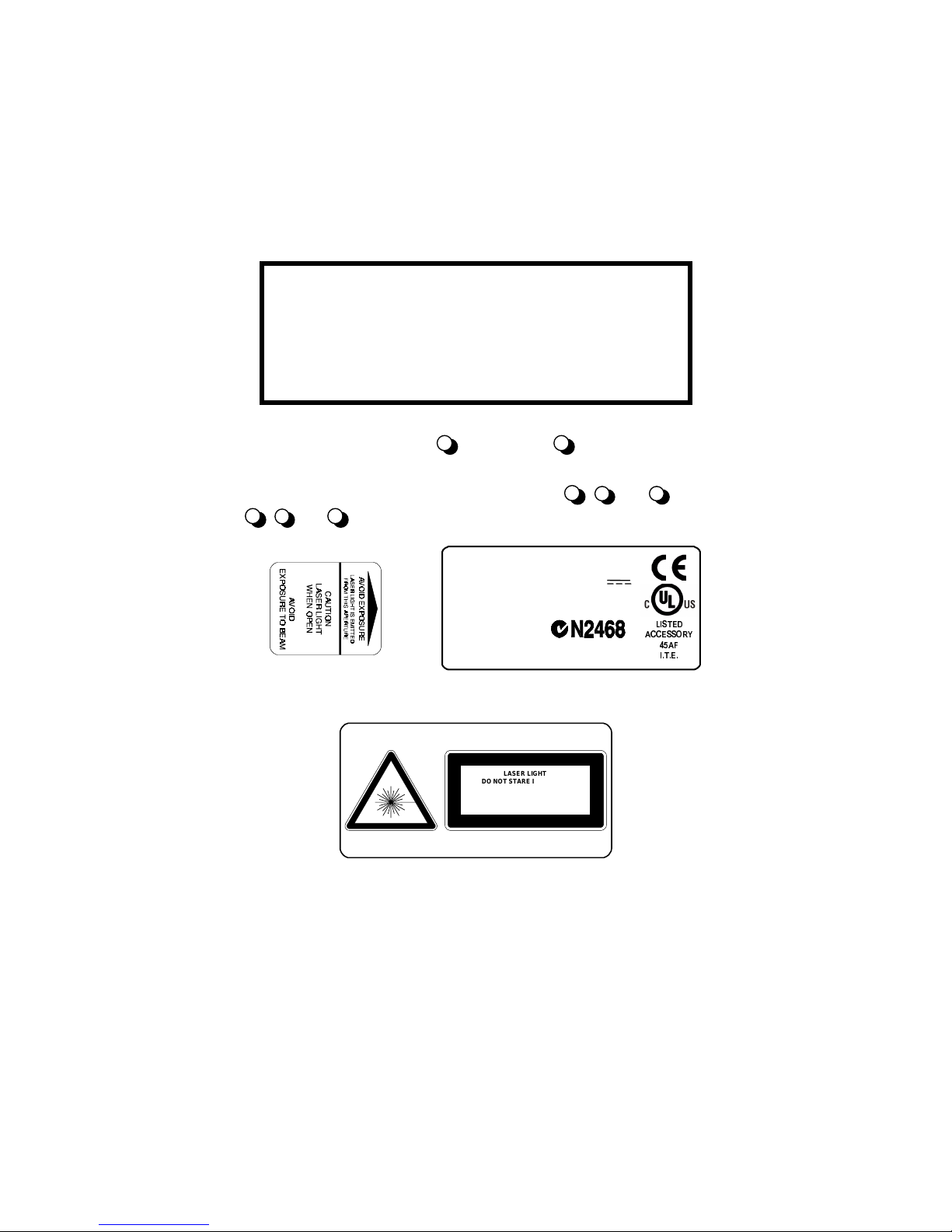
Warning labels indicating ex posure to las er light and the device c lass ification
are applied onto the body of the scanner (Figure A,
2
, 10
and
11
, Figure
B,
2
,
3
and
4
):
Model No. Amp.
Serial No.
DATALOGIC S.P.A. Via Candini, 2
40012 Calderara di Reno - Bologna - Italy
Manufa c t ured Volt
This product conforms to the applicable requirements
of 21CFR1040 at the date of manufacture.
LASER LIGHT
DO NOT STARE INTO BEAM
CLASS 2 LASER PRODUCT
MAXIMUM OUTPUT RADIATION 1 mW
EMITTED WAVELENGTH 630~680 mW
TO IEC 825-1 (1993)
Warning and device class labels
Disconnect the power supply when opening the device during m aintenance or
installation to avoid exposure to hazardous laser light.
Page 10

ix
The laser diodes used in this device are classified as Class 3B laser products
according to IEC 825-1 regulations and as Clas s IIIb laser produc ts according
to CDRH regulations. As it is not p o ssible t o apply a classification label on the
laser diodes used in this device, the following label is reproduced here:
LASER LIGHT
AVOID EXPOSURE TO BE AM
CLASS 3B LASER PRODUCT
MAXIMUM OUTPUT RADIATION 30 mW
EMITTED WAVELENGTH 630~680 nm
TO IEC 825-1 (1993)
Laser diode class label
Any violation of the optic parts in particular can cause radiation up to the
maximum level of the laser diode (30 mW at 630~680 nm).
POWER SUPPLY
This scanner is intended to be supplied by either a UL Listed power supply
marked 'Class 2' or 'LPS', output rated 20 - 30 V dc , m inimum 1.0 A or by a
UL Listed computer with LPS outputs.
In any case, all models of DS8100 must be supplied by a Class II Power
Supply Unit conforming to the EN 60950 safety regulation.
Page 11

x
This page is intentionally lef t blank.
Page 12

DATALOGIC DS8100
General features -
2.1
1 GENERAL FEATURES
1.1 INTRODUCTION
The DS8100 scanner is a barcode reader complete with decoder des igned to
provide an innovative and high performance solution in omnidirectional
reading applications by combining the following advanc ed technologies with
Datalogic’s solid experience in the material handling sector.
ACR™
Advanced Code Reconstruction technology allows the reading of low aspect
ratio labels placed anywhere on a parcel and enhances the readability of
poorly printed or damaged codes.
CD SQUARE™
CD SQUARE™ provides useful information on label position and object
shape elaborated during the barcode reading phase. This innovative
technology identifies the area in which the code is located and measures the
code distance from the scanner.
PACKTRACK™
PackTrack ™ is a Datalogic patented parcel trac king system which im proves
the reading features in omnidirectional stations. In particular, PackTrack™
manages 6-sided reading systems when it is im possible to detect the real
position of the code on the parcel, thus overcoming the need for external
accessories essential in traditional tracking systems.
ASTRA™
Automatically SwiTched Reading Area™ is the new Datalogic technology
based on a multi-laser architec ture and a fixed mounted optic system which
concentrates the multiple laser emissions in a single laser beam. As each
laser emitter is focused on a specific range of the reading area, a
sophisticated electronic controller select s the best focused laser emitter with
Page 13

DS8100 DATALOGIC
2.2
- General features
respect to the code to read. This allows the reading of medium- high density
codes in a large reading area on very fast conveyors.
TBS™
Twin Beam System™ improves the reading of c odes covered by plastic film
or wrapping material. The optic architec ture is able to c hange the laser diode
path and to adapt the beam’s skew angle on the code to read. This makes
the scanner insensitive to direct reflections and to the bars’ distortion caused
by the plastic film.
Single-scanner and Multi-scanner Applications
DS8100 Serial Interface version is provided with two standard interfaces
allowing easy use and connection and is therefore suitable f or single-reader
applications.
DS8100 Bus Interface version is particularly suited for multi-scanner
applications. It is provided with a Lonworks network for connections with
other DS8100s and with an SC8000 unit which performs real time data
collection and control of the reading station.
Flexibility
The high frequency laser diode modulation system guarantees complete
immunity to ambient light and allows installation of the DS8100 in any
working area.
The DS8100 Serial Interface is easy configurable by means of the W indowsbased user-friendly Winhost utility program provided on diskette.
It can also be configured from a Host PC through the Hos t Mode procedure
or using the built-in keypad through the Keyboard Mode procedure.
Page 14

DATALOGIC DS8100
General features -
2.3
1.2 DESCRIPTION
Some of the main features of DS8100 are listed below:
•
scanning speed 1000 scans/sec. for standard models; higher speeds
available on request.
•
reads all popular codes.
•
supply voltage from 20 to 30 Vdc.
•
test modes to verify the reading features and exact positioning of the
scanner without the need for external tools.
•
programmable in 5 different operating modes to suit the most various
barcode reading system requirements.
•
light source: solid state laser diodes; the light emitted has a wave length
of 630~680 nm. For laser safety precautions refer to the “Safety
precautions” section at the beginning of this manual.
•
2 serial communication interfaces for Serial Interface models.
Page 15

DS8100 DATALOGIC
2.4
- General features
1.2.1 Indicators - DS8100 Serial Interface
The DS8100 Serial Interface has six LEDs and an LCD display on the front panel.
The indicators have the following functions:
Power ON:
LED (green). Indicates the scanner is ON. (Figure A,
3
).
Ext Trig:
LED (yellow). Indicates the external presence sensor is active.
(Figure A,
4
).
Encoder:
LED (yellow). Indicates the external encoder si
g
nal is active
(when provided). (Figure A,
9
).
Good Read:
LED (red). Indicates a code is present in the readin
g
zone.
(Figure A,
6
).
TX Data:
LED (
g
reen). Indicates data transmission both on the m ain
and on the auxiliary interface. (Figure A,
7
).
User Defined:
LED (red). The use of this indicator depends on the
application. (Figure A,
8
).
LCD display:
The LCD displays messa
g
es relative to the DS8100
confi
g
uration and to the code read after decoding. It is a 2 x
20 character display. (Figure A,
5
).
1.2.2 Indicators - DS8100 Bus Interface
The DS8100 Bus Interface has six LEDs on the rear panel.
The indicators have the following functions:
Power ON:
LED (red). Indicates the scanner is ON. (Figure B,
5
).
Ext Trig:
LED (yellow). Indicates the external presence sensor is active.
(Figure B,
6
).
Encoder:
LED (
g
reen). Indicates the external encoder signal is active
(when provided). (Figure B,
7
).
Good
Read:
LED (red). Indicates a probable code is present in the readin
g
zone. (Figure B, 8).
TX Data:
LED (
g
reen). Indicates data transmission both on the main and
on the auxiliary interface. (Figure B,
10
).
Network:
LED (red). In a normal situation, this LED is OFF. If the LED blinks,
check the connections between the DS8100 and the SC8000.
When this LED is ON, the network card needs to be
reprogrammed. Contact your Datalogic distributor. (Figure B,
11
).
Page 16

DATALOGIC DS8100
General features -
2.5
1.3 AVAILABLE MODELS
The DS8100 scanner is available in four versions that differ depending on the
system of connection and on the laser number:
DS8100 - X X 0 0
Communication Type:
0 = Bus Interface version
1 = Serial Interface version
Laser number:
2 = Double laser
4 = Quad. laser
1.4 ACCESSORIES
The following DS8100 accessories are available on request:
•
Power supply unit
•
90° deflection mirror
•
Oscillating mirror
•
XMF-10 Single cross metal frame
•
XMF-20 Double cross metal frame
•
FBK-8100 Fast bracket kit
•
US-8100 Bracket kit
•
CAB-8101 1.2 m. DS8100-DS8100 Connection cable
•
CAB-8102 2.5 m. DS8100-DS8100 Connection cable
•
CAB-8105 5 m. DS8100-DS8100 Connection cable
•
CAB-8005 5 m. DS8100-SC8000/Host Connection cable
•
CAB-8010 10 m. DS8100-SC8000/Host Connection cable
•
BTK-8100 Bus terminator kit for DS8100 Lonworks version
Page 17

DS8100 DATALOGIC
2.6
- General features
1.5 APPLICATIONS
The DS8100 barcode reader is specifically designed for industrial
applications and for all cases requiring high reading performance such as:
•
code reconstruction
•
reading of codes covered by plastic film
•
reading of codes with a wide depth of field
•
reading of high resolution codes positioned at long distances from the
reader
•
barcode reading combined with parcel dimensioning
•
code reading on fast moving objects.
DS8100 is designed for both single-reader layouts and m ulti-reader layouts.
For typical layouts see par. 2.7 and 3.6.
Page 18
DATALOGIC DS8100
Installation — DS8100 Serial I nterface -
2.1
2 INSTALLATION — DS8100 SERIAL INTERFACE
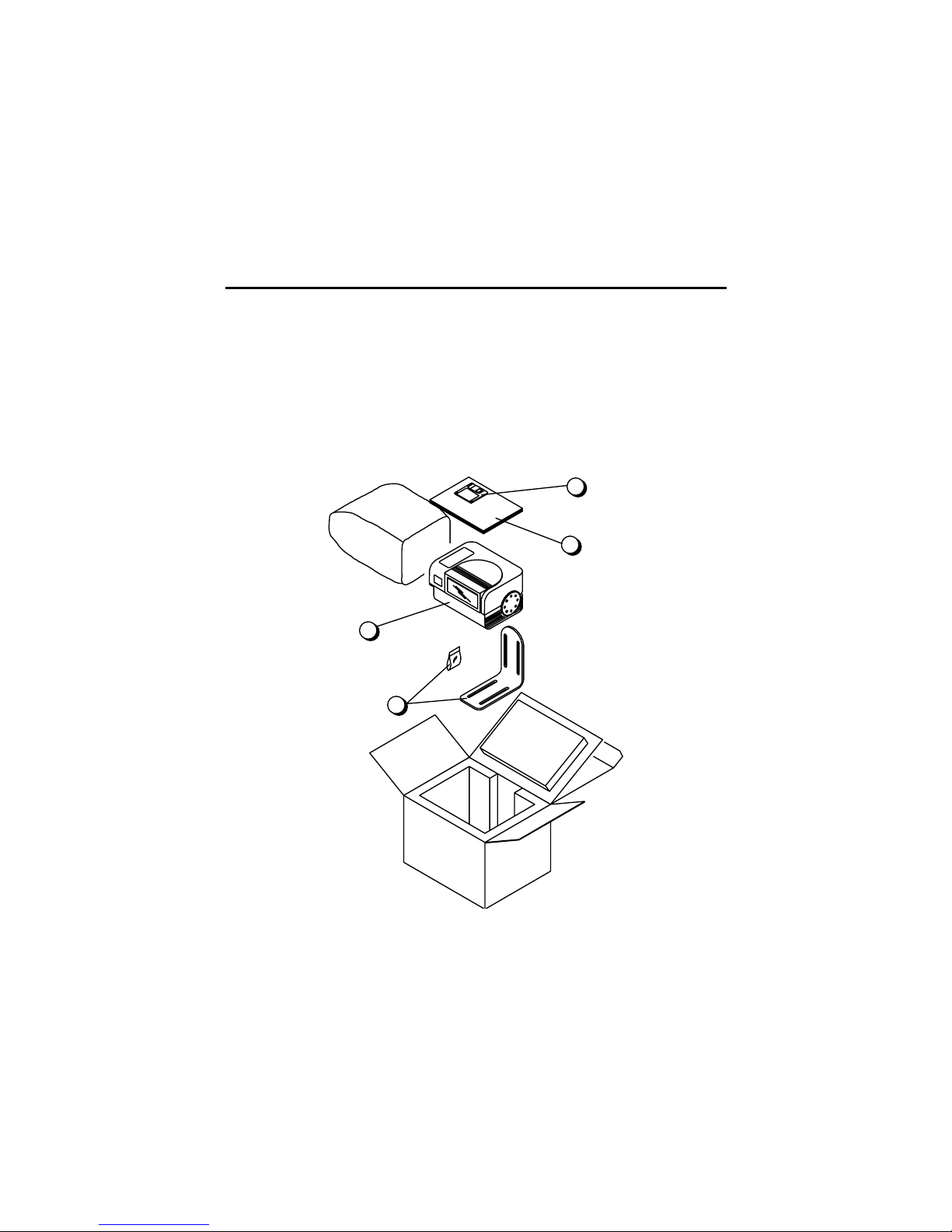
2.1 PACKAGE CONTENTS
Verify that the DS8100 reader and all the parts supplied with the equipment
are present and intact when opening the packaging; the list of parts includes:
1. DS8100 reader
2. Installation Manual + barcode test chart
3. DS8100 configuration disk
4. Mounting bracket and screws
1
2
3
4
Figure 2.1 - DS8100 package contents
Page 19

DS8100 DATALOGIC
2.2
- Installation — DS8100 Serial I nterface
2.2 GUIDE TO INSTALLATION
The following can be used as a checklist to verify all the necessary steps for
complete installation of the DS8100 scanner.
1. Read all information in the s ection Safety Precautions at the beginning of
this manual.
2. Correct ly position and mount the scanner f or barcode reading according
to the information in paragraphs 2.3, 2.4 and 2.6.
3. Provide correct system cabling according to the signals necessary (see all
applicable sub-paragraphs under 2.5).
4. Install the Configuration Disk and configure the s oftware param eters f rom
a host computer using one of the following methods:
•
WINHOST interface utility program. For more details refer to the
section “DS8100 Configuration” in the WINHOST Help On Line.
•
Host Mode programming pr ocedure by ESC sequences via the serial
interface. For more details refer to the Word docum ent hds 8100.doc in
the DS8100 directory.
•
Keyboard Mode through the keypad and the display. For more details
refer to the Word document kds8100.doc in the DS8100 directory.
NOTE
Fine tuning of the scanner position for barcode
reading can be accomplished using the T est Mode
as described in WINHOST.
The installation is now complete.
Page 20

DATALOGIC DS8100
Installation — DS8100 Serial I nterface -
2.3
2.3 OPENING THE SCANNER
Before installing the DS8100 Serial Interface m odel, it may be necessar y to
open the scanner to select the Main interface type and the Multidrop Address
(see par. 2.3.1 and 2.3.2)
WARNING
Before unscrewing the display panel of the DS8100,
make sure the power supply cable is disconnected
to avoid shock or harm to the operator
.
The following operation should be performed by
qualified personnel only.
Refer to the following instructions and Figure 2.2 when opening the reader:
1. The part of the device to be opened is the display panel.
2. Unscrew the six screws to open the scanner.
3. Carefully remove the panel as shown in Figure 2.2.
Figure 2.2 - Opening the DS8100
!
Page 21

DS8100 DATALOGIC
2.4
- Installation — DS8100 Serial I nterface
2.3.1 Main Interface Selection
The main serial interfac e of the DS8100 offers the f ollowing communication
types:
RS232
RS485 full-duplex
RS485 half-duplex
20 mA current loop
The RS232 interface is factory set.
To select the interface type:
1. Remove the panel as described in par. 2.3.
2. Position the jumper onto the correct connector as indicated in Figure 2.3.
RS232
20 mA C.L.
RS485 half-duplex
RS485 full-duplex
DISPLAY
JUMPER
Can be aligned
at either edge
J3
J2
J1
J1
J2
J3
J3
Figure 2.3 - DS8100 main interface selecti o n
!
Page 22

DATALOGIC DS8100
Installation — DS8100 Serial I nterface -
2.5
2.3.2 Multidrop Address Selection
When using the RS485 half-duplex interfac e, the Multidrop Address m ust be
selected. Proceed as follows:
1. Open the panel as described in par. 2.3.
2. Position the switches as desired, referring to Figure 2.4.
DISPLAY
DIP SWITCH
ON
1
2
3
4
5
DIP
Figure 2.4 - DS8100 Multidrop Address selection
The following table shows the Multidrop Address settings where:
1 = ON 0 = OFF
Position Address Position Address
54321 54321
11111
31
01111
15
11110
30
01110
14
11101
29
01101
13
11100
28
01100
12
11011
27
01011
11
11010
26
01010
10
11001
25
01001
9
11000
24
01000
8
10111
23
00111
7
10110
22
00110
6
10101
21
00101
5
10100
20
00100
4
10011
19
00011
3
10010
18
00010
2
10001
17
00001
1
10000
16
00000
0
!
Page 23

DS8100 DATALOGIC
2.6
- Installation — DS8100 Serial I nterface
2.4 MECHANICAL INSTALLATION
DS8100 can be installed to operate in any position.
There are 16 screw holes (M6 X 8) on the sides of the scanner for mounting.
The diagram below gives all the infor mation required f or ins tallation; ref er to par.
2.6 for correct positioning of the scanner with respect to the code passage zone.
Figure 2.5 - DS8100 overall dimensions
MOUNTING BRACKET
Page 24

DATALOGIC DS8100
Installation — DS8100 Serial I nterface –
2.7
2.5 ELECTRICAL CONNECTIONS
2.5.1 DS8100 Connectors
The DS8100 Serial Interface version is equipped with 4 connectors for the
following signals:
Aux. Interface/Input Signal connector A(male, 17 pins) (Figure A,
13
).
Aux. Interface/Input Signal connector B(female, 17 pins) (Figure A,
14
).
Output Signal connector (female, 9 pins) (Figure A,
16
).
Main Interface connector (female, 9 pins) (Figure A,
15
).
Aux. Interface/Input Signal Connector A
A1
A2
1
15
scanner side
external view
Figure 2.6 - Aux. Interface/Input Signal connector A (male)
Aux. Interface/Input Signal Connector A pinout
Pin Name Function
A1 GND Ground
A2 VS Power Supply
1 GND485 RS485 Ground Reference
2 NC Not connected
3 NC Not connected
4 NC Not connected
5 NC Not connected
6 NC Not connected
7 NC Not connected
8 RXTX485+ Positive Transmit/Receive
9 RXTX485- Negative Transmit/Receive
10 ENC+ Encoder signal (Positive pin)
11 ENC- Encoder signal (Negative pin)
12 PS2+ Presence Sensor 2 signal (Positive pin)
13 PS2- Presence Sensor 2 signal (Negative pin)
14 PS1+ Presence Sensor 1 signal (Positive pin)
15 PS1- Presence Sensor 1 signal (Negative pin)
Page 25

DS8100 DATALOGIC
2.8
- Installation — DS8100 Serial I nterface
Aux. Interface/Input Signal Connector B
A1
A2
1
15
scanner side
external view
Figure 2.7 - Aux. Interface/Input Signal connector B (female)
Aux. Interface/Input Signal Connector B pinout
Pin Name Function
A1 GND ground
A2 VS power supply
1 GND485 RS485 ground reference
2 I.U. (
TXDEBUG
) only for service use
3 I.U. (
GNDDEBUG
) only for service use
4 I.U. (
RXDEBUG
) only for service use
5 GNDAUX232 auxiliary RS232 ground
6 RXAUX232 auxiliary RS232 input
7 TXAUX232 auxiliary RS232 output
8 RXTX485+ positive RS485 transmit/receive
9 RXTX485- negative RS485 transmit/receive
10 ENC+ encoder signal (positive pin)
11 ENC- encoder signal (negative pin)
12 PS2+ presence sensor 2 signal (positive pin)
13 PS2- presence sensor 2 signal (negative pin)
14 PS1+ presence sensor 1 signal (positive pin)
15 PS1- presence sensor 1 signal (negative pin)
Page 26

DATALOGIC DS8100
Installation — DS8100 Serial I nterface –
2.9
Output Signal Connector
5
1
69
Figure 2.8 - Output Signal connector
Output Signal Connector pinout
Pin Name Function
1 VS supply voltage (positive pin)
2 GND supply voltage (negative pin)
3 NO READ+ no read output (positive pin)
4 NO READ- no read output (negative pin)
5 RIGHT+ right code output (positive pin)
6 RIGHT- right code output (negative pin)
7 I.U. internal use
8 I.U. internal use
9
Main Interface Connector
5
1
69
Figure 2.9 - Main Interface connector
Main Interface Connector pinout
Pin RS232 RS485
full-duplex
RS485
half-duplex
20 mA C.L.
1 DRVREF
2 TXD TX485+ RTX485+ CLOUT+
3 RXD TX485- RTX485- CLOUT4 DRVIN
5 GND GNDRS485 GNDRS485
6 RS485CNTR
7 CTS RX485+ CLIN+
8 RTS RX485- CLIN9 DRVOUT
* The function of these pins depends on the interface type select ed.
Page 27

DS8100 DATALOGIC
2.10
- Installation — DS8100 Serial I nterface
2.5.2 Power Supply
The supply voltage for correct operation of the scanner must be between 20
and 30 VDC.
The max. power consumption is 30 W.
The power supply unit (optional) supplies the power necessary for the
DS8100 and allows mains power to be used.
A security system allows the laser to activate only once the motor has
reached the correct rotational speed; consequently, the laser beam is
generated after a slight delay from the power on of the scanner.
The switch (Figure A,
17
) on the connector panel turns off power to both the
motor and the laser beams.
During power up of the scanner there is a cur rent peak of about 3A caused
by the motor startup.
2.5.3 Main Serial Interface
The main serial interface of the DS8100 Serial Interface version is
compatible with the following electrical standards:
RS232
RS485 full-duplex
RS485 half-duplex
20 mA current loop
The configuration param eters of the selected inter face can be defined using
one of the programming methods available. For this procedure refer to the
WINHOST Help On Line shipped on the diskette.
The connections regarding the interface selected are described in the
following sections.
NOTE
The signals relative to the selected interface are only available
on the Main Interface connector if the jumper ins ide the sc anner
is correctly positioned. Refer to par. 2.3.1 for further details.
Page 28

DATALOGIC DS8100
Installation — DS8100 Serial I nterface –
2.11
RS232 Interface
The main serial interf ace is used in this c ase f or point to point connec tions; it
handles communication with the Host computer and allows both transmission
of code data and configuring the scanner.
The following pins of the Main Interface c onnector (Figure A,
15
) are used
for RS232 interface connection:
Pin Name Function
2 TXD transmitted data
3 RXD received data
5 GND ground
7 CTS clear to send
8 RTS request to send
DS8100 USER INTERFACE
TXD
RXD
CTS
RTS
GND
RXD
TXD
GND
2
3
7
8
5
Figure 2.10 - RS232 connections
The RTS and CTS signals control data transmission and synchronize the
connected devices.
If the RTS/CTS hardware protocol is enabled, the DS8100 activates the RTS
output to indicate a message can be transmitted. The receiving unit must
activate the CTS input to enable the transmission.
Page 29

DS8100 DATALOGIC
2.12
- Installation — DS8100 Serial I nterface
RS485 Full-Duplex Interface
The RS485 full-duplex interface is used for non-polled communication
protocols in point to point connections over longer distances than those
acceptable for RS232 communications or in electrically noisy environments.
The following pins of the Main Interface c onnector (Figure A,
15
) are used
for RS485 full-duplex communications:
Pin Name Function
2 TX485+ RS485 transmitted data +
3 TX485- RS485 transmitted data 5 GNDRS485 RS485 ground reference
7 RX485+ RS485 received data +
8 RX485- RS485 received data -
DS8100
5
GNDRS485
TX485+
2
TX485-
3
RX485+
7
RX485-
8
RX485
TX485
GND
USER INTERFACE
Figure 2.11 - RS485 full-duplex interface connections
Page 30

DATALOGIC DS8100
Installation — DS8100 Serial I nterface –
2.13
RS485 Half-Duplex Interface
The RS485 half-duplex (3 wires + shield) interface is used for polled
communication protocols. It can be used for Multidrop connections in a
master/slave layout or with a Datalogic Multiplexer, (see par. 2.7.3, 2.7.4 and
2.7.5).
Device connection to the Multidrop line can be controlled externally through
the RS485CNTR line. For example, it may be necessary to disconnect a
scanner from the line if the device is dam aged or the line is overloaded. To
do this, apply a voltage from 20 to 30 Vdc to the RS485CNTR signal using
the same GND of the power supply as a reference.
The following pins of the Main Interface c onnector (Figure A,
15
) are used
for RS485 half-duplex interface connection:
Pin Name Function
6 RS485CNTR multidrop device disconnect
2 RTX485+ transmit/receive data +
3 RTX485- transmit/receive data 5 GNDRS485 RS485 ground reference
GND
DS8100
USER INTERFACE
RXTX+
RTX485-
3
RXTX-
RTX485+
2
GND
5
GNDRS485
RS485GND
Vext
20 to 30 Vdc
RS485CNTR
6
VS
20 to 30 Vdc
±
Figure 2.12 - RS485 half-duplex interface connections
Page 31

DS8100 DATALOGIC
2.14
- Installation — DS8100 Serial I nterface
The figure below shows an example of a multidrop conf iguration between a
Multiplexer and DS8100 scanners.
120 Ohm
max. 1200 m.
DS8100
# x
(up to 31)
Multiplexer
RTX485+
RTX485-
shield
# 1
DS8100
120 Ohm
max. 2 m.
5
3
2
RTX485+
RTX485-
GNDRS485
# 0
DS8100
RS485REF
5
3
2
5
3
2
Figure 2.13 - DS8100 Multidrop connection to a M ultiplexer
Page 32

DATALOGIC DS8100
Installation — DS8100 Serial I nterface –
2.15
20 mA Current Loop Interface
The DS8100 has two current generators (one for transmission and one f or
reception), allowing for both active and passive type connections.
The following pins of the Main Interface c onnector ( F ig ur e A,
15
) are used for
20 mA C.L. connections:
Pin Name Function
1 DRVREF current generator reference
2 CLOUT+ current loop output +
3 CLOUT- current loop output 4 DRVIN input current generator
7 CLIN+ current loop input +
8 CLIN- current loop input 9 DRVOUT output current generator
DS8100
USER INTERFACE
MAX. 300 METERS
C.L. IN-
C.L. IN+
C.L. OUT-
C.L. OUT+
DRVREF
DRVIN
8
7
3
2
1
4
9
DRVOUT
I = 20 mA
I = 20 mA
Figure 2.14 - 20 mA C.L. active connections
Page 33

DS8100 DATALOGIC
2.16
- Installation — DS8100 Serial I nterface
DS8100
MAX. 300 METERS
8
C.L. IN-
7
C.L. IN+
3
C.L. OUT-
2
C.L. OUT+
USER INTERFACE
+
+
Figure 2.15 - 20 mA C.L. passive connections
2.5.4 Auxiliary Interface
The auxiliary serial interface of the DS8100 Serial Interface version is
equipped with both RS232 and RS485 half-duplex interface connections.
The signals for the auxiliary interface are available on the
Aux. Interface A
and B connectors to simplify the master/slave connections (Figure A,
13
and 14).
RS232 Auxiliary Interface
The following pins of the
Aux. Interface B connector
connector are used:
Pin Name Function
5 GNDAUX232 ground
6 RXAUX232 receive data
7 TXAUX232 transmit data
Page 34

DATALOGIC DS8100
Installation — DS8100 Serial I nterface –
2.17
TXD
RXAUX232
RXD
TXAUX232
7
5
GNDAUX232
GND
DS8100
USER INTERFACE
6
Figure 2.16 - RS232 Auxiliary interface connections
RS485 Half-Duplex Auxiliary Interface
The following pins of the
Aux. Interface A and B connectors
(Figure A,
13
and
14
) are used:
Pin Name Function
1 GND485 ground
8 RTX485+ transmit/receive data +
9 RTX485- transmit/receive data -
DS8100
USER INTERFACE
RTX485+
RTX485-
9
RTX485-
RTX485+
8
1
GND485
GND485
Figure 2.17 - RS485 Auxiliary interface connections
2.5.5 Inputs
The inputs of the scanner are on the
Input Signal A and B connectors
on
the body of the DS8100 (Figure A,
13
and
14
).
These inputs are called ENC, PS1 and PS2.
ENC is the Encoder input. In PackTrack™ operating mode, it detects the
conveyor speed.
Page 35

DS8100 DATALOGIC
2.18
- Installation — DS8100 Serial I nterface
PS1 is the main presence sensor (external trigger). When ac tive, this input
tells the scanner to scan for a c ode and that decoding can take plac e. The
yellow LED (Figure A,
4
) indicates that PS1 is active.
PS2 can be used as the stop signal for the reading phase.
All inputs are optocoupled and driven by a constant current generator; the
command signal is filtered through an anti-disturbance circuit which
generates a delay of about 5 ms for PS1 and PS2 and 500 µs for ENC.
PS2+/PS1+
PSIN
+
VS
12/14
13/15
A2
A1
GND
DS8100
PRESENCE SENSOR
PS2-/PS1-
Figure 2.18 - Presence sensor input PNP command
Signal
PSIN
+
12/14
13/15
A2
A1
PS2+/PS1+
PS2-/PS1-
VS
GND
Ground
PRESENCE SENSOR
DS8100
V
Figure 2.19 - Presence sensor input NPN command
Page 36

DATALOGIC DS8100
Installation — DS8100 Serial I nterface –
2.19
Signal
ENC+
ENC-
10
11
+ 5V
VS
A2
A1
GND
Ground
ENCODER
DS8100
V
Figure 2.20 - Encoder NPN input command using DS8100 power
Signal
ENCODER
ENC+
ENC-
10
11
+ 5V
DS8100
V
Vext
Figure 2.21 - Encoder NPN input command using external power
+
10
11
A2
A1
ENC+
ENC-
VS
GND
ENCODER
DS8100
Figure 2.22 - Encoder PNP input command using DS8100 pow er
Page 37

DS8100 DATALOGIC
2.20
- Installation — DS8100 Serial I nterface
ENCODER
Signal
DS8100
ENC+
ENC-
10
11
+ 5V
V
Vext
Figure 2.23 - Encoder PNP input command using external power
Isolation between the command logic and the scanner is maintained by
powering the inputs with a different supply voltage (Vext) from that supplied
on the
Aux. Interface/Input Signal A
and
B
connectors (VS).
The driving logic of the input signals m ay be powered, for convenience, with
the voltage supply between pins A2 (VS) and A1 (GND) of the connector. In
this case, however, the device is no longer electrically isolated.
The electrical features of these inputs are:
Maximum voltage 30 V
Maximum current 25 mA
Page 38

DATALOGIC DS8100
Installation — DS8100 Serial I nterface –
2.21
2.5.6 Outputs
The relative signals are available on the Output Signal connec tor (Figure A,
16
).
Pin Name Function
1 VS power for external devices (Positive pin)
2 GND power for external devices (Negative pin)
3 NO READ+ no read output +
4 NO READ- no read output 5 RIGHT+ right code output +
6 RIGHT- right code output 7
8
I.U.
I.U.
internal use
internal use
9 N.C. not connected
A D.C. output voltage, the same as that powering the DS8100, is present
between pins 1 and 2. This may be used to power external devices: electrical
isolation between the scanner and external devices is lost in this case.
The
No Read
output activates when a code signalled by the presence sensor
is not decoded.
The
Right
output is used to signal the presence of a right code, thus a good
decode condition.
All outputs are level or pulse program mable: a 50 ms pulse is generated in
the second case. Further programming information is supplied in the
WINHOST Help File.
These outputs are created using optoisolated Dar lington drivers and supply
both the collector and emitter in output, allowing both loads referenced to
ground and to the power supply to be driven.
The electrical features are given below:
Collector-emitter voltage 30 V Max.
Collector current 130 mA Max (pulsed).
Saturation voltage (VCE) 1 V at 10 mA Max.
Maximum power dissipation 90 mW at 50 °C (Ambient temperature).
Page 39

DS8100 DATALOGIC
2.22
- Installation — DS8100 Serial I nterface
DS8100
USER INTERFACE
NO READ+
RIGHT+
Vext
30 Vdc max
NO READ-
RIGHT-
3/5
4/6
Figure 2.24 - Output interface
When the load is powered by an external power supply, the voltage m ust be
less than 30 V. The limit requested by the maximum power dissipation is
more important than that of the maxim um collector current: if one of these
outputs is continuously driven, the maximum cur rent must not be mor e than
40 mA although 130 mA may be reached in pulse conditions.
2.6 POSITIONING
The DS8100 scanner is able to decode barcode labels at a variety of angles,
however significant angular distortion may degrade reading performance.
When mounting the DS8100 take into consideration these three ideal label
position angles:
Pitch 0°, Skew 0° to 45° and Tilt 0°
.
Follow the suggestions for the best orientation:
The
Pitch
angle is represented by the
value P in Figure 2.25. Position the
reader in order to minimize the Pitch
angle.
Figure 2.25 - "Pitch" angle
P
Page 40

DATALOGIC DS8100
Installation — DS8100 Serial I nterface –
2.23
The
Skew
angle is represented by the value S in Figure 2.26.
S
Figure 2.26 - "Skew" angle
The
Tilt
angle is represented by the value T in Figure 2.27. For code
reconstruction, see par. 4.1.1.
T
Figure 2.27 - "Tilt" angle
Page 41

DS8100 DATALOGIC
2.24
- Installation — DS8100 Serial I nterface
2.7 TYPICAL LAYOUTS
2.7.1 Standard (Point-to-Point)
In this layout, data is transmitted to the Host on the main serial interface. The
selectable interface types are RS232, RS485 full-duplex or 20 mA C.L.
communications.
1
Host
3
Presence sensor (for On-Line mode)
3
Main serial interface
1
DS8100
Auxiliary serial interface
2
2
Terminal
Figure 2.28 - Standard (point to point) layout
When On-Line Operating mode is used, the scanner is activated by an
External Trigger (presence sensor) when the object enters its reading zone.
The data is also transmitted on the Auxiliary interface (if configured for
Standard communication mode), as well as on the Main interface.
The
auxiliary interface uses RS232 for this layout.
Host Mode programming can be accomplished either thr ough the Main or the
Auxiliary interface.
Page 42

DATALOGIC DS8100
Installation — DS8100 Serial I nterface –
2.25
2.7.2 Pass Through
Pass Through Mode allows two or more devic es to be connected to a single
external serial interface. The DS8100 tr ans mits the messages rec eived by its
auxiliary interface (RS232 only) onto its main interface.
In this configuration a series of s canners can be connected together using
RS232 on the main interface and all messages will be passed through this
chain to the host.
The reading phase of each scanner is independent from the others in a Pas s
Through chain.
When On-Line Operating mode is used, the scanner is
activated by an External Trigger (presence sensor) when the object enter s its
reading zone.
Applications can be implem ented to connect a device such as a hand-held
reader to the Auxiliary port for manual code reading capability.
3 3
1
Main serial interface
2
Auxiliary serial interface
3
Presence sensor (for On-Line mode)
Host
DS8100 DS8100
Hand-Held reader
1
2
1
Figure 2.29 - Pass through layout
Page 43

DS8100 DATALOGIC
2.26
- Installation — DS8100 Serial I nterface
2.7.3 RS485 Master/Slave
The RS485 Master/Slave connection is used to collect data from several
scanners to build either an omni-directional or multi-sided reading system;
there can be one Master and up to 8 Slaves connected together.
The Master and Slave scanners are connected together using RS485 halfduplex on the auxiliary serial interface.
The Master scanner is also connected to either a Host or a Multiplexer on the
main serial interface. T he possible main inter face type selections are RS232
or RS485 full-duplex for Host connections or RS485 half-duplex for
Multiplexer connections (see “Main Interface Selection” in par. 2.3.1).
For the Slave scanners the Multidrop Address Selection can be m ade using
the DIP switch. The addresses m ust be consec utive and not inc lude zero for
hardware configuration, or be selected in software (in this case the DIP
switch address must be zero for each Slave). See par. 2.3.2.
NOTE
The main serial port of the Slave scanners can be used
for configuration. The termination r esistors of the RS485
bus must not be installed.
Single P.S.
The P.S. signal is unique to the system; there is a single reading phase and
a single message from the master scanner to the Host.
Presence sensor
3
Auxiliary serial interface: RS485 half-duplex
2
Main serial interface
1
HOST
PC or PLC
RS232
RS485 full-duplex
MULTIPLEXER
MX4000
RS485 half-duplex
Slave
Master
2
Slave
DS8100
DS8100
DS8100
1
3
Figure 2.30 - Master-slave Single P.S . l ayout
Page 44

DATALOGIC DS8100
Installation — DS8100 Serial I nterface –
2.27
Multi P.S.
In this layout, each DS8100 has its own P.S. and therefore multiple reading
phases. The master sends the individual messages collected from the
multidrop line as well as its own to the Host.
DS8100
3
Main serial interface
Auxiliary serial interface: RS485 half-duplex
Presence sensor (for On-Line mode)
3
2
1
Slave
DS8100
Master
3
2
2
1
HOST
PC or PLC
RS232
RS485 full-duplex
MULTIPLEXER
MX4000
RS485 half-duplex
Figure 2.31 - Multi P.S. layout connections
2.7.4 Multiplexer
Each scanner is connected to an MX4000 us ing RS485 half-duplex on either
the main or the auxiliary interface. The other interface can be used for
configuration.
Host
MX4000
01 31
P.S.
P.S.
P.S.
Figure 2.32 - Multiplexer layout
Page 45

DS8100 DATALOGIC
2.28
- Installation — DS8100 Serial I nterface
2.7.5 Omnidirectional Reading
Two or more scanner s are cor rectly positioned in a Master/Slave Single P.S.
type layout to compose an omnidirectional reading station.
The XMF series metal frames provide easy mounting for this type of layout.
P.S.
PHOTOCELL
code motion
READING
AREA
Figure 2.33 - Omnidirectional reading
Page 46

DATALOGIC DS8100
Installation — DS8100 Bus Interface -
3.1
3 INSTALLATION — DS8100 BUS INTERFACE
3.1 PACKAGE CONTENTS
Verify that the DS8100 reader and all the parts supplied with the equipment
are present and intact when opening the packaging; the list of parts includes:
1. DS8100 reader
2. Installation Manual + barcode test chart
3. Mounting bracket and screws
1
3
2
Figure 3.1 - DS8100 package contents
Page 47

DS8100 DATALOGIC
3.2
- Installation — DS8100 Bus Interface
3.2 GUIDE TO INSTALLATION
The following can be used as a checklist to verify all the necessary steps for
complete installation of the DS8100 scanner.
1. Read all information in the s ection Safety Precautions at the beginning of
this manual.
2. Correct ly position and mount the scanner f or barcode reading according
to the information in paragraphs 3.3 and 3.5.
3. Provide correct s ystem cabling according to the s ignals necessary (see
paragraph 3.4 and 3.6).
4. Configure your DS8100 by means of the SC8000 unit.
NOTE
Fine tuning of the scanner position for barcode
reading can be accomplished by performing a test
through the SC8000 unit.
The installation is now complete.
Page 48

DATALOGIC DS8100
Installation — DS8100 Bus Interface -
3.3
3.3 MECHANICAL INSTALLATION
DS8100 can be installed to operate in any position.
There are 16 screw holes (M6 X 8) on the sides of the scanner for mounting.
The diagram below gives all the infor mation required f or ins tallation; ref er to par.
3.5 for correct positioning of the scanner with respect to the code passage zone.
Figure 3.2 - DS8100 Bus Interface overall dimensions
MOUNTING BRACKET
Page 49

DS8100 DATALOGIC
3.4
- Installation — DS8100 Bus Interface
3.4 ELECTRICAL CONNECTIONS
The DS8100 Bus Interface version employs a Lonworks network used for
both input and output connections to build a multi-sided or omni-station
system connecting several DS8100 scanners and one or more SC8000
units.
This version is equipped with the following 3 connectors:
•
Lonworks INPUT male connector (17 pins) (Figure B,
12
).
•
Lonworks OUTPUT female connector (17 pins) (Figure B,
13
).
•
RS232 debug connector – for Service only, (9 pins) (Figure B,
14
).
Lonworks INPUT/OUTPUT Connector
A1
A2
1
15
scanner side
external view
A1
A2
1
15
OUTPUT
INPUT
Figure 3.3 - Lonworks INPUT/OUTPUT connectors
The following pinout is valid for the INPUT connector as well as for the
OUTPUT connector.
Lonworks INPUT/OUTPUT Connector pinout
Pin Name Function
A1 GND supply voltage (negative pin)
A2 VS supply voltage 20 to 30 vdc (positive pin)
1 Shield A
3 Shield B
8 Lon A+ lonworks a line (positive pin)
9 Lon A- lonworks a line (negative pin)
10 Lon B+ lonworks b line (positive pin)
11 Lon B- lonworks b line (negative pin)
12 PS+ presence sensor
13 ENC+ encoder input
14 PSAux+ auxiliary presence sensor
15 Refer- input reference
Page 50

DATALOGIC DS8100
Installation — DS8100 Bus Interface –
3.5
RS232 Debug Connector
The use of this connector is reserved for Service:
5
1
69
Figure 3.4 - RS232 debug connector
RS232 Debug Connector pinout
Pin Name Function
2 TXD transmit data
3 RXD receive data
5 GND ground
3.4.1 Power Supply
The supply voltage for correct operation of the scanner must be between 20
and 30 VDC.
The max. power consumption is 30 W.
The power block (optional), supplies the power necessary for the DS8100
and allows mains power to be used.
A security system allows the laser to activate only once the motor has
reached the correct rotational speed; consequently, the laser beam is
generated after a slight delay from the power on of the scanner.
The switch (Figure B,
15
) on the connector panel turns off power to both the
motor and the laser beams.
During power up of the scanner there is a cur rent peak of about 3A caused
by the motor startup.
Page 51

DS8100 DATALOGIC
3.6
- Installation — DS8100 Bus Interface
3.4.2 Inputs
The inputs for the DS8100 Bus Interface version are provided by SC8000
and are called ENC, PS and PSAux.
ENC is the Encoder input. In PackTrack™ operating mode, it detects the
conveyor speed.
PS is the main presence sensor (external trigger). W hen active, this input
tells the scanner to scan for a c ode and that decoding can take plac e. The
yellow LED (Figure B,
6
) indicates that PS is active.
PSAux can be used in special applications.
All inputs are optocoupled and driven by a constant current generator; the
command signal is filtered through an anti-disturbance circuit which
generates a delay of about 5 ms for PS and PSAux and 500 µs for ENC.
REFER-
DS8100 SC8000
Vext
20-30 Vdc
PS
12
Vext
20-30 Vdc
PSAux
13
Vext
20-30 Vdc
ENC
14
15
Figure 3.5 - DS8100 Bus Interface inputs
Page 52

DATALOGIC DS8100
Installation — DS8100 Bus Interface –
3.7
3.5 POSITIONING
The DS8100 scanner is able to decode barcode labels at a variety of angles,
however significant angular distortion may degrade reading performance.
When mounting the DS8100 take into consideration these three ideal label
position angles:
Pitch 0°, Skew 0° to 45° and Tilt 0°
.
Follow the suggestions for the best orientation:
The
Pitch
angle is represented by the value P in Figure 3.6. Position the
reader in order to
minimize
the
Pitch
angle.
P
Figure 3.6 - "Pitch" angle
The
Skew
angle is represented by the value S in Figure 3.7.
S
Figure 3.7 - "Skew" angle
Page 53

DS8100 DATALOGIC
3.8
- Installation — DS8100 Bus Interface
The
Tilt
angle is represented by the value T in Figure 3.8. For code
reconstruction, see par. 4.1.1.
T
Figure 3.8 - "Tilt" angle
3.6 Typical Layout
The scanner is generally activated by a photoelectric sensor used as a code
presence sensor when the object enters its reading zone.
The following figures show a typical layout for DS8100 Bus Interface.
A Lonworks cable provides a communic ation line (branch) between up to 4
scanners and an SC8000 unit. The last scanner on the line requires a
Termination connector. Up to 4 br anches of this type can be connected to a
single SC8000. The allowed maximum length of the cable is 65 m.
External devices such as a presence sensor , an encoder and the supply unit
are all connected to the SC8000, which collects all signals driving them to all
scanners.
The SC8000 is also connected to a Host.
Page 54

DATALOGIC DS8100
Installation — DS8100 Bus Interface –
3.9
ENCODER
PRESENCE
SENSOR
1
2
34
9
10
11 12
13
14
15 16
SC8000
DATALOGIC
POWER SUPPLY
UNIT
HOST
CAB-8101
CAB-8102
CAB-8105
5
6
78
BKT-8100
CAB-8005
CAB-8010
Figure 3.9 - DS8100 Bus Interface Typical Layout
Page 55

DS8100 DATALOGIC
3.10
- Installation — DS8100 Bus Interface
CONVEYOR
SC8000
Figure 3.10 - DS8100 Bus Interface typical application
Page 56

DATALOGIC DS8100
Reading features -
4.1
4 READING FEATURES
4.1 ADVANCED CODE RECONSTRUCTION
The traditional way of barcode reading could be called "Linear Reading". In
this case, the laser beam cros ses the barcode symbol from its beginning to
its end as shown in Figure 4.1.
Laser Beam
Figure 4.1 - Linear reading
In "Advanced Code Reconstruction" mode, it is no longer necessary for the
laser beam to cross the label from the start to the end. W ith just a set of
partial scans on the label (obtained using the motion of the label itself), the
DS8100 is able to "reconstruct" the barcode. A typical set of partial scans is
shown in Figure 4.2.
Code Direction
Figure 4.2 - Partial scans
None of the partial scans contains the whole label. The decoder aligns each
partial scan correctly and combines them in order to obtain the entire code.
The alignment is performed by calculating the time difference from one
partial scan to another using a reference code element.
4.1.1 Tilt Angle For Advanced Code Reconstruction
The most important parameter in Advanced Code Reconstruction is the
value of the maximum tilt angle (α maximum) under which the code
reconstruction process is still possible.
Page 57

DS8100 DATALOGIC
4.2
- Reading features
We define the T ilt angle as the angle (α) between the laser beam and a line
parallel to the barcode label, as shown in Figure 4.3.
α
Laser Beam
= tilt an
g
le
α
0° toαmax
Figure 4.3 - Tilt angle
The formulas to calculate α maximum depend on various parameters such
as: label height, number of scans per second, code motion speed, etc. To
obtain α maximum for your application, please contact your Datalogic
representative.
You must remember that the decoder will be able to read the label with a tilt
angle between + α max and - α max as shown in Figure 4.4 (the shaded
zones are the NO READ zones).
Laser Beam
α
-
+
α
0°
Figure 4.4 - Reading zones with α max
4.2 PERFORMANCE
The scan rate is 1000 scans/sec.
Refer to the diagrams in par. 4.3 for further details on the reading features.
These diagrams are taken on various resolution sam ple codes at a 25 °C
ambient temperature depending on the conditions listed under each diagram.
If standard models do not satis fy specific requirem ents, contac t your nearest
Datalogic distributor, supplying code samples, to obtain complete inf orm ation
on the reading possibilities.
Page 58

DATALOGIC DS8100
Reading features -
4.3
4.3 READING DIAGRAMS
The following diagram shows the reading distance for barc odes with diff erent
densities for DS8100-2x00 (double laser models).
Note: (0,0) is the center of the laser beam output window
-600
-400
-200
0
200
400
600
0
200 400 600 800
1000 1200 1400 1600
1800
2000 2200
0.50 mm
(mm)
Figure 4.5
-
Reading diagram for DS8100
Code = Interleaved 2/5 or Code 39
PCS = 0.90
"Pitch" angle = 0°
"Skew" angle = 10°
"Tilt" angle = 0°
Reading mode = Linear
Page 59

DS8100 DATALOGIC
4.4
- Reading features
The following diagram shows the reading distance for barc odes with diff erent
densities for DS8100-4x00 (quad laser models).
Note: (0,0) is the center of the laser beam output window
-600
-400
-200
0
200
400
600
0
200 400 600 800
1000 1200 1400 1600
1800
2000 2200
0.50 mm
(mm)
0.30 mm
Figure 4.6
-
Reading diagram for DS8100
Code = Interleaved 2/5 or Code 39
PCS = 0.90
"Pitch" angle = 0°
"Skew" angle = 10°
"Tilt" angle = 0°
Reading mode = Linear
Page 60

DATALOGIC DS8100
Maintenance -
5.1
5 MAINTENANCE
5.1 CLEANING
Clean the laser beam output window (Figure A and Figure B, 1) periodically
for correct operation of the reader.
Dust, dirt, etc. on the window may alter the reading performance.
Repeat the operation frequently in particularly dirty environments.
Use soft material and alcohol to c lean the window and avoid any abrasive
substances.
WARNING
Clean the window of the DS8100
when the scanner is turned off or at
least when the laser beam is not
active.
Page 61

DS8100 DATALOGIC
5.2
- Maintenance
This page is intentionally lef t blank.
Page 62

DATALOGIC DS8100
Technical Features -
6.1
6 TECHNICAL FEATURES
DS8100 model
Serial Interface Bus Interface
ELECTRICAL FEATURES
(see note 1)
Maximum input voltage 35 Vdc
Supply voltage 20 to 30 Vdc
Operating current 1.3 - 0.9 A
Power consumption 30 W
INPUTS/OUTPUTS
Serial interfaces
Main RS232
RS485 Lonworks network
20 mA C.L.
Auxiliary RS232, RS485
Baud Rates 1200 to 1.25 Mb/s
Command inputs (NPN or PNP ) Presence sensor (optocoupled)
Encoder input (optocoupled)
Auxiliary input (optocoupled)
Outputs NO READ (optocoupled)
(open emitter or collect or) RIGHT CODE (optocoupled)
OPTICAL FEATURES
(see note 1)
Light source up to 4 semiconductor laser diodes
Wave length 630 to 680 nm
Safety class Class 2 - IEC 825-1; Class II - CDRH
Light receiver Avalanche photodiode
READING FEATURES
Scan rate 1000 scans/s
Maximum resolution
Max. reading distance (see reading diagram in par. 4.3)
Max. reading width
Max. depth of field
Aperture angle
USER INTERFACE
LCD Display:
2 lines, 20 characters
4 key keypad
LED indicators Power ON, Ext Trig,
Encoder, Good Read, TX
Data, User Defined
Power ON, Ext Trig,
Encoder, Good Read, TX
Data, Network.
Page 63

DS8100 DATALOGIC
6.2
- Technical Features
DS8100 model
Serial Interface Bus Interface
SOFTWARE FEATURES
Readable code symbologies
• Interleaved 2/5 • Code 128
• Code 39 Standard • EAN128
• EAN/UPC
Code selection
Up to 5 code symbologies during one reading phase
Decoding safety
Several good reads of the same code can be enabled
separately for each code
Headers and Terminators
Transmitted messages can be personalized using up to 4
headers and 4 terminators
Operating modes
ON LINE
SERIAL ON LINE Depending on SC8000
AUTOMATIC
TEST
PACK TRACK™
Configuration modes
WINHOST utility program
SC8000
KEYBOARD MODE:
using the built-in keypad
HOST MODE:
receiving commands from the
serial port
Parameter storage
Non-volatile internal
EEPROM
ENVIRONMENTAL FEATURES
Operating temperature 0 to 40 °C
Storage temperature -20 to 70 °C
Humidity 90% non condensing
Vibration resistance IEC 68-2-6 test FC
1.5 mm; 10 to 55 Hz;
2 hours on each axis
Shock resistance IEC 68-2-27 test EA
30 G; 11 ms;
3 shocks on each axis
Protection Class IP64
PHYSICAL FEATURES
Mechanical dimensions 215.5 x 170.5 x 126.5 mm
Weight 5 Kg
Note 1
: The features given are typical at 25 °C ambient temperature (if not otherwise
indicated).
 Loading...