

Page 1

DS6100
Installation Manual
Page 2

DS6100
INSTALLATION MANUAL
Page 3

We
DATALOGIC S.p.A.
Via Candini, 2
40012 - Lippo di Calderara
Bologna - Italy
declare under our sole responsibility that the product
DS6100-XXXX, Laser Scanner and all its models
to which this declarat ion relates is in conf ormi ty with the fol lowing standards or other norm ati ve
documents
EN 55022, August 1994
EN 50082-2, March 1995
EN 60950, October 1996
EN 60825, March 1993
:R
:L
IMITS AND METHODS OF MEASUREMENTS OF RADIO DISTURBANCE
CHARACTERISTICS OF INFORMATION TECHNOLOGY EQUIPMENT
LECTROMAGNETIC COMPATIBILITY
:E
ART
P
AFETY OF INFORMATION TECHNOLOGY EQUIPMENT, INCLUDING
:S
ELECTRICAL BUSINESS EQUIPMENT
ADIATION SAFETY OF LASER PRODUCTS
CLASSIFICATION
NDUSTRIAL ENVIRONMENT
2: I
Following the provision of the Directive(s):
89/336 CEE
AND SUCCESSIVE AMENDMENTS
Lippo di Calderara, 23.03.1998
ENERIC IMMUNITY STANDARD
. G
REQUIREMENTS AND USER’S GUIDE
,
, 92/31 CEE; 93/68 CEE; 73/23 CEE
Ruggero Cacioppo
Quality Assurance Supervisor
EQUIPMENT
,
(ITE)
.
Product names ment ioned herein are for identification purposes only and may be trademarks
and or registered trademarks of their respect i ve companies.
Datalogic reserves t he ri ght to make m odi f i cations and improvements without prior notification.
© 1997, 1998, 1999 Datalogic S.p.A.
821000105 (Rev. E)
Page 4

CONTENTS
GUIDE TO INSTALLATION
SAFETY PRECAUTIONS
...............................................................v
................................................................viii
Electrical Safety................................................................................viii
Laser Safety......................................................................................viii
Standard Regulations.......................................................................viii
1 GENERAL FEATURES
...................................................................1.1
1.1 Introduction......................................................................................1.1
1.2 Description.......................................................................................1.2
1.2.1 Indicators.........................................................................................1.3
1.3 Available Models..............................................................................1.3
1.4 Accessories .....................................................................................1.4
1.5 Applications .....................................................................................1.4
2 INSTALLATION
..............................................................................2.1
2.1 Package Contents ...........................................................................2.1
2.2 Opening The Scanner......................................................................2.2
2.2.1 Multidrop Address Selection............................................................2.4
2.2.2 Input Selection.................................................................................2.6
2.3 Mechanical Installation ....................................................................2.7
2.4 Junction Box Installation..................................................................2.9
2.4.1 Junction Box Mounting ....................................................................2.9
2.4.2 Junction Box Electrical Connections..............................................2.10
2.5 Electrical Connections for Connector Models................................2.13
2.5.1 Power Supply.................................................................................2.16
2.5.2 Main Serial Interface......................................................................2.16
RS232 Interface.............................................................................2.17
RS485 Full-Duplex Interface..........................................................2.18
RS485 Half-Duplex Interface.........................................................2.19
20 mA Current Loop (INT-26 Accessory Only).............................2.21
2.5.3 Auxiliary Interface..........................................................................2.22
2.5.4 Inputs.............................................................................................2.23
2.5.5 Outputs..........................................................................................2.26
2.6 Positioning.....................................................................................2.27
2.7 Focus Adjustment..........................................................................2.29
2.8 Typical Layouts..............................................................................2.30
2.8.1 Standard (Point-to-Point)...............................................................2.30
2.8.2 Pass Through ................................................................................2.31
iii
Page 5

2.8.3 RS485 Master/Slave......................................................................2.31
2.8.4 Multiplexer .....................................................................................2.33
2.8.5 MUX24HS......................................................................................2.34
2.8.6 PackTrack Omnidirectional Reading.............................................2.34
3 READING FEATURES
....................................................................3.1
3.1 Advanced Code Reconstruction......................................................3.1
3.1.1 Tilt Angle for Advanced Code Reconstruction.................................3.1
3.2 Performance....................................................................................3.2
3.3 Reading Diagrams...........................................................................3.2
4 MAINTENANCE
..............................................................................4.1
4.1 Cleaning...........................................................................................4.1
5 TECHNICAL FEATURES
................................................................5.1
iv
Page 6

GUIDE TO INSTALLATION
The following can be used as a checklist to verif y all the necessary steps for
complete installation of the DS6100 scanner.
1. Read all information in the s ection Safety Precautions at the beginning of
this manual.
2. Correctly position and mount the scanner for barcode reading according
to the information in paragraphs 2.2, 2.3, 2.6, 2.8 and 3.3.
3. Provide correct system cabling according to the signals necessary (see
the applicable sub-paragraphs under 2.4 or 2.5).
4. Install the Configuration Disk and configure the s oftware param eters f rom
a host computer using one of the following methods:
•
WINHOST interface utility program. For more details refer to the
section “DS6100 Configuration” in the WINHOST Help On Line.
•
Host Mode programm ing procedure by ESC sequences via the serial
interface. For more details r ef er to the Word document hds6100.doc in
the DS6100 directory.
•
Keyboard Mode through the keypad and the display. For more details
refer to the Word document kds6100.doc in the DS6100 directory.
NOTE
Fine tuning of the scanner position for
barcode reading can be accom plished using
the Test Mode as described in WINHOST.
The installation is now complete.
v
Page 7
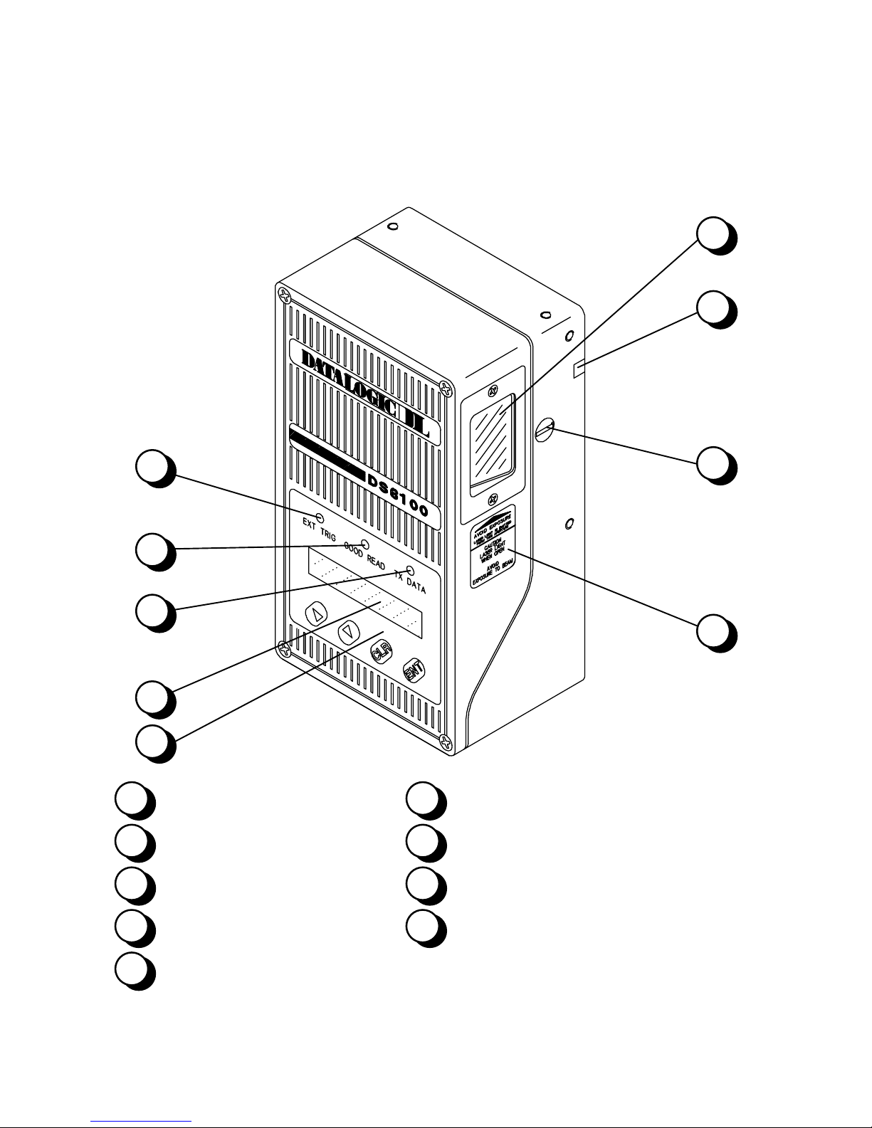
DS6100
General View
1
2
9
8
7
6
5
Laser beam output window
1
Laser active LED
2
LCD 2x16 characters
6
Data transmission LED
7
3
4
Focus regulation cover
3
Safety label
4
Keypad
5
vi
Code present LED
8
Presence sensor LED
9
Figure A
Page 8

10
11
DS6100
General View
DS6100
Connector model
13
14
Warning and device class labels
10
Product label
11
Output / Serial interface connector
12
Power supply connector
13
12
15
Figure B
17
DS6100
JBOX model
Input connector
14
Oscillating mirror connector
15
Power supply switch
16
Junction box cable
17
16
15
vii
Page 9
SAFETY PRECAUTIONS
ELECTRICAL SAFETY
This product conforms to the applicable requirements contained in the
European Standard for electrical safety EN-60950 at the date of manufacture.
This symbol refers to operations that must be performed by
!
LASER SAFETY
The following information is provided to comply with the rules imposed by
international authorities and refers to the correct use of the DS6100 scanner.
qualified personnel only.
This symbol refers to operations where there is danger of
electrical shock.
cable is disconnected to avoid electric shock.
Before opening the device make sure the power
Example: opening the device.
Standard Regulations
This scanner utilizes a low-power laser diode. Although star ing directly at the
laser beam mom entarily causes no known biological damage, avoid staring
at the beam as one would with any very strong light source, such as the sun.
Avoid that the laser beam hits the eye of an observer , even through r ef lec tive
surfaces such as mirrors, etc.
This product conform s to the applicable requirem ents of both IEC 825-1 and
CDRH 21 CFR 1040 at the date of manufac ture. T he s c anner is c lass if ied as
a Class 2 laser produc t according to IEC 825-1 regulations and as a Cl ass I I
laser product according to CDRH regulations.
There is a saf ety device which allows the laser to be switched on only if the
motor is rotating above the threshold for its correct scanning speed.
viii
Page 10
WARNING
f
Use of controls or adjustments or performance of
procedures other than those specified herein may result
in exposure to hazardous visible laser light.
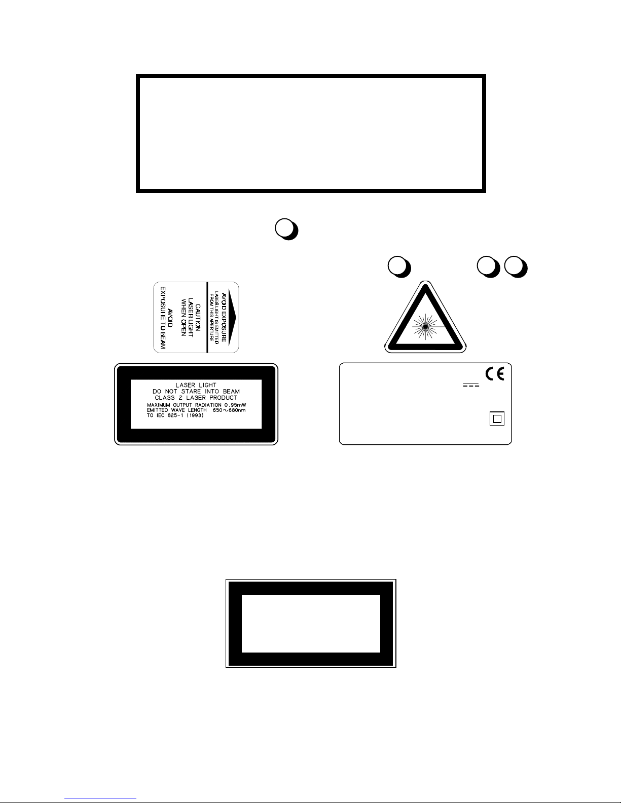
The laser light is visible to the hum an eye and is em itted f rom the window on
the side of the reader (Figure A,
W arning labels indicating expos ure to las er light and the devic e c lassif ication
are applied onto the body of the scanner (Figure A,
).
1
, Figure B,
4
DATALOGIC S.P.A. Via Candini, 2
40012 LIPPO DI CALDERARA (BO) ITALY
Manufact ur ed Volt
Model No. Amp.
Serial No.
10,11
):
This product conforms to the applicable requirements o
21CFR1040 at the date of manufacture.
Warning and device class label s
Disconnect the power supply when opening the device during maintenance or
installation to avoid exposure to hazardous laser light.
The laser diode used in this device is classified as a Class 3B laser product
according to IEC 825-1 regulations and as a Class IIIb laser product according
to CDRH regulations. As it is n o t p o ssibl e t o apply a classification label on the
laser diode used in this device, the following label is reproduced here:
LASER LIGHT
AVOID EXPO SUR E TO BEAM
CLASS 3B LASER PRO DUCT
MAXIMUM OUTPUT RADIATION 10 mW
EMITTED WAVE LENGTH 650~680 nm
TO IEC 825-1 (1993)
Laser diode class label
Any violation of the optic parts in particular can cause radiation up to the
maximum level of the laser diode (10 mW at 650~680 nm).
ix
Page 11

x
This page is intenti onal l y l ef t blank.
Page 12

DATALOGIC DS6100
1 GENERAL FEATURES
1.1 INTRODUCTION
The DS6100 scanner is a barcode reader complete with decoder designed to
provide an inexpensive solution in omnidirectional reading applications by
combining the following advanced technologies with Datalogic’s solid
experience in the material handling sector.
ACR™
Advanced Code Reconstruction Technology allows the reading of low aspect
ratio labels placed anywhere on a parcel and enhances the readability of
poorly printed or damaged codes.
CD SQUARE™
CD SQUARE™ provides useful information on label position and object
shape elaborated during the barcode reading phase. This innovative
technology identifies the area in which the code is located and m easures the
code distance from the scanner.
PACKTRACK™
PackTr ack™ is a Datalogic patented par cel tracking system which improves
the reading features in omnidirectional stations. In particular, PackTrack™
manages 6-sided reading systems when it is impossible to detect the real
position of the code on the parcel, thus overcoming the need for external
accessories essential in traditional tracking systems.
Flexibility
The high frequency laser diode modulation system guarantees complete
immunity to ambient light and allows installation of the DS6100 in any
working area.
General Features -
1.1
Page 13

DS6100 DATALOGIC
DS6100 is provided with an Adjustable Focus System which enables the user
to freely select the most suitable reading field for his application. Focus
length can be very easily adjusted by choosing among six diff erent positions
of the optical system.
DS6100 is easily configurable by means of the us er-friendly W indows based
W inHost configuration program provided on a dis kette. It is also possible to
configure the scanner either through the built-in keypad or by sending ESC
sequences from a Host computer.
1.2 DESCRIPTION
Some of the main features of DS6100 are listed below:
•
scanning speed 800 scans/sec. for standard models; higher speeds
available on request.
•
2 serial communication interfaces.
•
reads all popular codes.
•
supply voltage from 10 to 30 Vdc.
•
electrical connection through connectors or through a junction box.
•
test mode to verify the reading features and exact positioning of the
scanner without the need for external tools.
•
programmable in 5 different operating modes to suit the most various
barcode reading system requirements.
•
light source: solid state laser diode; the light emitted has a wave length of
650~680 nm. For laser safety precautions refer to the “Safety
precautions” section at the beginning of this manual.
•
low power consumption.
•
IP65 protection class of the enclosure; the reader is therefore suitable for
industrial environments where high protection against harsh external
conditions is required.
- General Features
1.2
Page 14

DATALOGIC DS6100
g
g
g
g
g
1.2.1 Indicators
The DS6100 has three LEDs and an LCD display on the front panel, one
LED on the side panel and an internal beeper.
The indicators have the following functions:
EXT TRIG
(yellow) Indicates the external presence sensor is
active. (Figure A,
GOOD READ
(red) Indicates a probable code is present in the
reading zone. (Figure A,
TX DATA
(green) Indicates the main s erial interface is operatin
correctly during data transmission. (Figure A,
7
LASER ACTIVE
(green) Indicates the laser beam for barcode readin
is active. (Figure A,
LCD
The LCD displays messa
DS6100 confi
after decodin
(Figure A,
1.3 AVAILABLE MODELS
).
).
9
).
8
).
2
es relative to the
uration and to the code read
. It is a 2 x 16 character display.
).
6
The DS6100 scanner is available in the following versions:
DS6100 – 3000
DS6100 – 3100
standard resolution, connector,
:
nd
generation ACR, sw selection of interfaces
2
standard resolution, junction box,
:
nd
generation ACR, sw selection of interfaces
2
General Features -
1.3
Page 15

DS6100 DATALOGIC
1.4 ACCESSORIES
The following DS6100 accessories are available on request:
PG110/50 Power block (110 Vac)
PG220/50 Power block (220 Vac)
GFC-50 90° reading device
GFC-05 oscillating mirror attachment
US-1 installation support
XMF-05 single cross mounting frame
XBOX-05 connection box single/double cross (for Junction Box models only)
VOY-05 Voyager kit for XBOX-05
US-05 mounting brackets (10 pcs)
INT-26 20 mA C.L. interface module
1.5 APPLICATIONS
The DS6100 barcode reader was specifically designed for industrial
applications and for all cases requiring high reading performance such as:
•
code reconstruction
•
reading of codes with a wide depth of field
•
reading of high resolution codes positioned at long distances from the
reader
•
code reading on fast moving objects
DS6100 is designed for both single-r eader layouts and multi- reader layouts.
For typical layouts see par. 2.8.
- General Features
1.4
Page 16
DATALOGIC DS6100
2 INSTALLATION
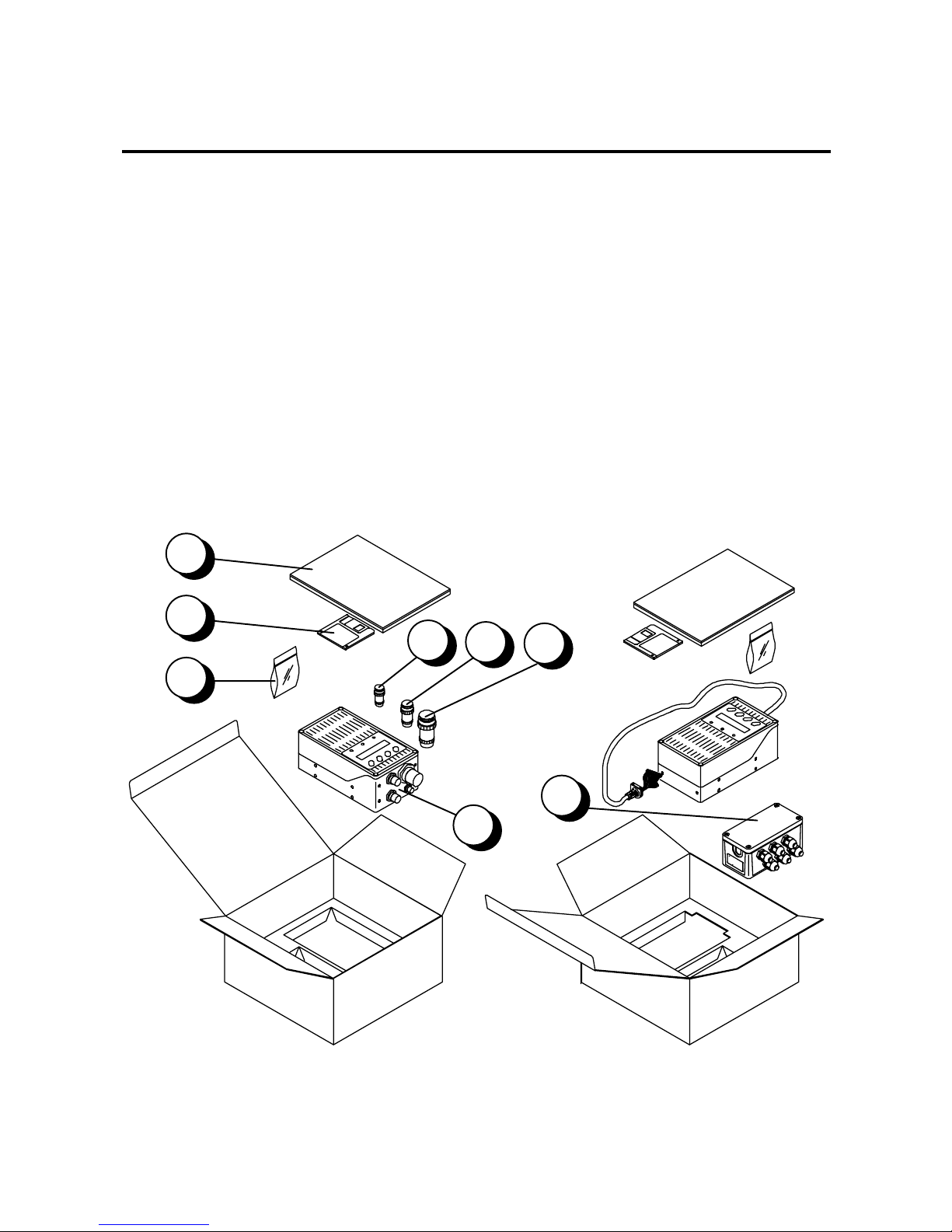
2.1 PACKAGE CONTENTS
Verify that the DS6100 reader and all the parts supplied with the equipment
are present and intact when opening the packaging; the list of parts includes:
1) DS6100 reader
2) Installation Manual + barcode test chart
3) DS6100 configuration disk
4) Mounting screws
Connector version Junction Box version
5) 3-pin female connector (power supply) 8) JBOX
6) 6-pin male connector (inputs)
7) 19-pin male connector (outputs)
2
3
5
6
7
4
8
1
Figure 2.1 - DS6100 package contents
Installation -
2.1
Page 17
DS6100 DATALOGIC
2.2 OPENING THE SCANNER
!
DS6100 scanners can be completely configured through sof tware using one
of the three methods listed in the "Guide to Installation" at the beginning of
this manual. The s canner theref ore can be ins talled without the necessity of
opening it to configure hardware switches.
To determine if it is necessary to open the scanner for hardware
configuration of your application, the default hardware settings are listed
below:
•
Multidrop address selection =
•
Inputs =
To change the default settings, before installing the DS6100, refer to the
procedures in the following paragraphs:
•
setting the multidrop address (hardware configuration) see par. 2.2.1
•
select the input type see par. 2.2.2
NPN
address 0
(software configurable)
WARNING
Before unscrewing the connector or cable
panel of the DS6100, mak e sure the power
supply cable is disconnected to avoid shock
or harm to the operator.
Refer to the following instructions and ref er to Figure 2.2 when opening the
reader:
1. The part of the device to be opened is the connector or cable panel on the
side of the scanner.
2. Unscrew the four screws to open the scanner.
- Installation
2.2
Page 18
DATALOGIC DS6100
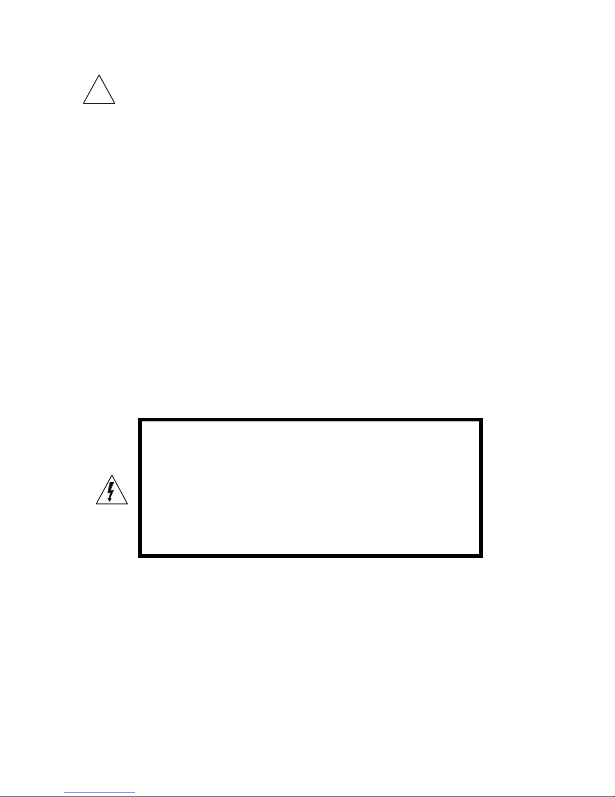
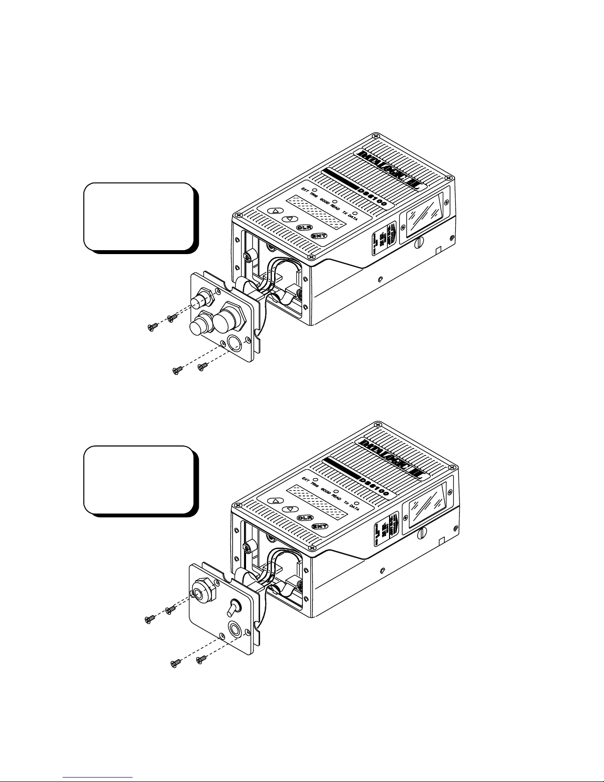
3. Carefully remove the panel as shown in Figure 2.2. Pay attention not to
stretch the cables between the panel and the scanner.
DS6100
CONNECTOR
MODEL
DS6100
JUNCTION BOX
MODEL
Figure 2.2 - Opening the DS6100
Installation -
2.3
Page 19

DS6100 DATALOGIC
2.2.1 Multidrop Address Selection
!
W hen using the RS485 half-duplex inter face, the Multidr op address must be
selected.
The Multidrop Address can be selected either via software or through the DIP
switch. Refer to the WinHost Help On Line for software selection.
To set the Multidrop Address through the DIP switch proceed as follows:
1. Open the panel as described in par. 2.2.
2. Position the switches as desired, referring to Figure 2.3.
Connector Panel Junction Box Cable Panel
DS6100
DS6100
5
4
3
2
1
ON
Dip Switch
Dip Switc h
3
4
5
Figure 2.3 – DS6100 Multi d rop Address Selection
12
ON
- Installation
2.4
Page 20

DATALOGIC DS6100
The following table shows the Multidrop address settings where:
1 = ON 0 = OFF
Position Address Position Address
54321 54321
11111 31 01111 15
11110 30 01110 14
11101 29 01101 13
11100 28 01100 12
11011 27 01011 11
11010 26 01010 10
11001 25 01001 9
11000 24 01000 8
10111 23 00111 7
10110 22 00110 6
10101 21 00101 5
10100 20 00100 4
10011 19 00011 3
10010 18 00010 2
10001 17 00001 1
10000 16 00000 0
Address 0
is the default which allows software configuration.
Installation -
2.5
Page 21

DS6100 DATALOGIC
2.2.2 Input Selection
!
Two presence sensor inputs are provided (PS1 and PS2).
They can be selected as both positive inputs (PNP) or as both negative
inputs (NPN).
To select the Input type proceed as follows:
1. Open the panel as described in par. 2.2.
2. Position the jumpers as desired, referring to Figure 2.4.
Connector Panel Junction Box Cable Panel
NPN
PNP
Figure 2.4 – Input selection for DS6100
NPN
PNP
- Installation
2.6
Page 22

DATALOGIC DS6100
2.3 MECHANICAL INSTALLATION
DS6100 can be installed to operate in any position.
There are 16 screw holes (M5 X 8) on the sides of the scanner for mounting.
The diagrams below give all the inform ation required for installation; r efer to
par. 2.6 for correct positioning of the scanner with respect to the code
passage zone.
mm
in
Figure 2.5 - DS6100 overall dimensions - connector model
Installation -
2.7
Page 23

DS6100 DATALOGIC
Figure 2.6 - DS6100 overall dimensions - junction box model.
- Installation
2.8
mm
in
Page 24

DATALOGIC DS6100
2.4 JUNCTION BOX INSTALLATION
The junction box provides a passive connection between your scanner and
the outside world in a fast and practical way. It represents an alternative to
other standard connectors provided. Figure 2.7 shows the basic layout of a
scanner using the junction box.
For junction box connections, the scanner has a cable that terminates in a
24-pin connector that plugs into the
junction box. The system cables
pass through 6 glands in the side of
the junction box and the individual
wires connect to spring clamp
terminal blocks inside which provide
access to all scanner signals.
Scanner cable
DS6100
System cables
Figure 2.7 - Scanner using junction box
Junction Box
Refer to Figure 2.6 for the overall dimensions of the junction box.
2.4.1 Junction Box Mounting
The junction box is designed to be mounted to a panel of metal, plastic or
other appropriate material using the mounting screws provided in the
package. To do this:
1) Open the junction box by unscrewing the 4 cover screws.
If necessary, using the two mounting holes inside the junction box as a
pattern, mark the panel with an
appropriate object and then drill two small
pilot holes in the panel.
2) Align the junction box and insert the two
self-threading screws with their washers
and screw them into the panel until tight
(see Figure 2.8).
Figure 2.8 - Junction box mounting
Installation -
2.9
Page 25

DS6100 DATALOGIC
2.4.2 Junction Box Electrical Connections
The connection and wiring procedure for the junction box is described as
follows:
1) Open the junction box by unscrewing the 4 cover screws.
2) Pass all System cables through the glands in the junction box housing.
3) To connect the power and input/output signals:
•
Prepare the individual wires of the system cables by stripping the
insulation back approximately 11 mm.
•
Us ing a device such as a sc rewdriver, push down on the orange lever
directly above the clamp (see Figure 2.9).
•
Insert the wire into the clamp and release the lever.
The wire will now be held in the spring clamp.
Figure 2.9 - System cable connections to the junction box
The wiring used can be solid or stranded but must meet the following
specifications:
Positions 1-4: 24 - 16 AWG 0,2 - 1,5 mm
Positions 5-39: 26 - 20 AWG 0,14 - 0,5 mm
- Installation
2.10
2
2
Page 26

DATALOGIC DS6100
The junction box pinouts are indicated in the following table:
18 39
117
J1
Figure 2.10 - Junction box connector and pinout
5
J. BOX Pinout for DS6100
Pin Name Pin Name
01
02
03
04
05
06
07
08
09
10
11
12
13
14
15
16
17
18
19
20
VS
GND
VS
GND
CHASSIS
VS
VS
ENC+
ENCGND
GND
VS
VS
PS1+/PS2+/GND
GND
NOREAD+
NOREADRIGHT+
21
22
23
*24
*25
*26
27
28
29
30
31
32
33
34
35
36
37
38
39
RIGHTSPS+
SPS-
Main interface s i gnal s
SGND
TXA
AUX485+
SGND
RXA
AUX485-
see table below
Pin RS232 RS485
24,29
25,30
26,31
27
28
32
33
The signals on pins 24, 25, and 26 are repeated on pins 29, 30, and 31 to f acilitate network
*
connections (i. e. Multiplexer using the RS485 half-duplex interface). In this way the network
bus can enter and exit the junction box from different spring clamps but be physically
connected together.
TX232 TX485+ RTX485+ CL OUT+
RTS232 TX485- RTX485- CL OUT-
SGND CLGND
RX232 RX485+ CL IN+
CTS232 RX485- CL IN-
RS485
full-duplex
GNDRS485 GNDRS485 DRVOUT
half-duplex
RS485CNTR DRVIN
20 mA C.L.
(INT-26 Only)
Installation -
2.11
Page 27

DS6100 DATALOGIC
4) After wiring the junction box and while the scanner is unplugged from the
power, place the Scanner cable so that the rubber seal fits into the cutout
in the housing of the junction box and plug the 24-pin connector into
connector J1 on the PCB inside the junction box as shown in Figure 2.11.
Rubber seal
Scanner cable
Figure 2.11 - Scanner cable connections to the junction box
J1
5) Close the junction box using the 4 cover screws making sure the rubber
seal is fitted correctly between the parts of the housing.
The junction box is now installed which completes the elec trical connections
for your scanning system.
If it ever becomes necessary to disconnect the scanner from the junction
box, simply reverse the procedure in step 4.
- Installation
2.12
Page 28

DATALOGIC DS6100
2.5 ELECTRICAL CONNECTIONS FOR CONNECTOR
MODELS
DS6100 is available with two different electrical connection systems:
DS6100 junction box version
It is equipped with a cable that connects the junction box which houses
spring clamp terminal bloc k s for the connections to the power supply and the
input/output signals (refer to par. 2.4).
DS6100 connector version
It is equipped with 4 connectors for the following signals:
•
Power supply (male, 3 pins) (Figure B,
•
Presence sensors (female, 6 pins) (Figure B,
•
Output/Serial interfaces (female, 19 pins) (Figure B,
•
Oscillating mirror (female, 2 pins) (Figure B,
Power supply connector
GND
TO DS6100
CHASSIS
Figure 2.12 - Power supply connector
Power supply pinout
VS (10 to 30 VDC)
13
14
12
15
)
)
)
)
Pin Name Function
A GND Supply voltage B VS Supply voltage +
C CHASSIS Chassis Ground
Installation -
2.13
Page 29

DS6100 DATALOGIC
Input connector
GND
PS2+/-
ENC-
ENC+
Figure 2.13 - Input connector
VS
PS1+/-
Input pinout
Pin Name Function
A VS Power for external devices +
B GND Power for external devices C PS2+/- Presence sensor 2
D PS1+/- Presence sensor 1
E ENC+ Encoder (Positive pin)
F ENC- Encoder (Negative pin)
Oscillating mirror connector
12
VS1
Figure 2.14 - Oscillating mirror connector
Oscillating mirror pinout
Pin Name Function
1 VS1 Supply voltage (output) +
2 GND Supply voltage (output) -
This output passes the oper ating power supply voltage from the scanner to
the oscillating mirror . It is physically the same as the input power supplied to
the DS6100.
GND
- Installation
2.14
Page 30

DATALOGIC DS6100
(
Output/Serial interface connector
(A) GND
(B) VS (N) SGND
C) NO READ-
(D) NO READ+
(E) RIGHT-
(F) RIGHT+
(R)(P)
(T)(S) (U)P2(V)
P1
P3 P6P4 P5
Figure 2.15 - Output/Serial interface connector
Output/Serial interface pinout
Pin Name Function
A GND supply voltage B VS supply voltage +
C NO READ- no read output
D NO READ+ no read output
E RIGHT- right code output
F RIGHT+ right code out put
G SPS- slave presence sensor
H SPS+ slave presence sensor
JRXA
K AUX485+
LTXA
M AUX485-
Auxiliary serial interface
(see par. 2.6.3)
(M) AUX485-
(L) TXA
(K) AUX485+
(J) RXA
(H) SPS+
(G) SPS-
NSGND CLGND
P RTS232 TX485- RTX485- CL OUTR TX232 TX485+ RTX485+ CL OUT+
S CTS232 RX485- CL IN-
Main ser ial
interface
(see par. 2.6.2)
T RX232 RX485+ CL IN+
U RS485CNTR DRVIN
V
RS232 RS485
full-duplex
GNDRS485 GNDRS485 DRVOUT
RS485
half-duplex
20 mA C.L.
(INT-26 Only)
Installation -
2.15
Page 31

DS6100 DATALOGIC
2.5.1 Power Supply
The supply voltage for correct operation of the scanner mus t be between 10
and 30 VDC.
The max. power consumption is 10 W.
The power block (optional), supplies the power necessary for the DS6100
and allows mains power to be used.
A security system allows the laser to activate only once the motor has
reached the correct rotational speed; consequently, the laser beam is
generated after a slight delay from the power on of the scanner.
2.5.2 Main Serial Interface
The main serial interface is compatible with the following electrical standards:
RS232
RS485 full-duplex
RS485 half-duplex
20 mA current loop
The 20 mA Current Loop interface is available if the optional INT-26
accessory is installed. This accessory interface replaces the RS232/RS485
selections.
The main serial interface type and its relative parameters (baud rate,
data bits, etc.) are selected via software either using the WinHost utility
program or Host Mode programming. For more details refer to the
section "Main Interface Menu" in the WinHost Help On Line.
Details regarding the connections and use of the main interfac e selection ar e
given in the next paragraphs.
- Installation
2.16
Page 32

DATALOGIC DS6100
RS232 Interface
The main serial interfac e is used in this c ase f or point-to- point connec tions; it
handles communication with the Host computer and allows both transmission
of code data and configuring the scanner.
The following pins of the 19-pin connector are used for RS232 interface
connection:
Pin Name Function
R TX232 transmit data
T RX232 receive data
P RTS232 request to send
S CTS232 clear to send
N SGND signal ground
The RTS and CTS signals control data transmission and synchronize the
connected devices.
If the RTS/CTS har dware protocol is enabled, the DS6100 ac tivates the RTS
output to indicate a message can be transmitted. The receiving unit must
activate the CTS input to enable the transmission.
RTS232
TX232
CTS232
DS6100
USER INTER FACE
T
RX232
R
TX232
P
RTS232
S
CTS232
N
SGND
TXD
RXD
SGND
SGND
RX232
Figure 2.16 - RS232 connections
Installation -
2.17
Page 33

DS6100 DATALOGIC
RS485 Full-Duplex Interface
The RS485 full-duplex interface is used for non-polled communication
protocols in point-to-point connections over longer distances than those
acceptable for RS232 communications or in electrically noisy environments.
The following pins of the 19-pin connector are used for RS232 interface
connection:
Pin Name Function
R TX485+ RS485 transmit data +
P TX485- RS485 transmit data -
T RX485+ RS485 receive data +
S RX485- RS485 receive data V GNDRS485 RS485 ground reference
TX485+ TX485-
DS6100
R
P
T
S
RX485+RX485-
TX485+
TX485-
RX485+
RX485-
GNDRS485
USER INTERFACE
RX485
TX485
Figure 2.17 - RS485 full-duplex interface connecti ons
- Installation
2.18
V
GNDRS485
GND
Page 34

DATALOGIC DS6100
RS485 Half-Duplex Interface
The RS485 half-duplex (3 wires + shield) interface is used for polled
communication protocols.
It can be used for Multidrop connections in a master-slave layout or with a
Datalogic Multiplexer, (see par. 2.8.3, 2.8.4 and 2.8.5).
Device connection to the Multidrop line can be contr olled exter nally through the
RS485CNTR line. For exam ple, it may be necessary to disconnect a scanner
from the line if the device is damaged or the line is overloaded. To do this,
apply a voltage from 12 to 30 Vdc to the RS485CNTR signal using GND as a
reference.
The following pins of the 19-pin connector are used for RS232 interface
connection:
Pin Name Function
R RTX485+ RS485 transmit/receive data +
P RTX485- RS485 transmit/receive data V GNDRS485 RS485 ground reference
U RS485CNTR multidrop device disconnect
RTX485-
RS485CNTR
RTX485+
DS6100
VS
B
V
GNDRS485
R
RTX485+
P
RTX485-
U
RS485CNTR
Vext
12 to 30 Vdc
1
7
6
USER INTERFACE
RS485GND
RXTX+
RXTX-
GNDRS485
Figure 2.18 - RS485 half-duplex interface connecti ons
A
GND
GND
Installation -
2.19
Page 35

DS6100 DATALOGIC
The figure below shows a multidrop configuration with DS6100 scanners
connected to a Multiplexer.
DS6100
# x
(up to 31)
DS6100
# 1
DS6100
# 0
MULTIPLEXER
max. 2 m.
R
P
V
R
P
V
RTX485+
R
RTX485-
P
GNDRS485
V
RTX485+
RTX485-
RS485REF
120 Ohm
max. 1200 m .
120 Ohm
Figure 2.19 - DS6100 Multidrop connection to a Multiplexer
- Installation
2.20
Page 36

DATALOGIC DS6100
20 mA Current Loop (INT-26 Accessory Only)
W hen the INT-26 access ory board is installed, the DS6100 is equipped with
a 20 mA current loop interface. The INT -26 board supports both active and
passive type connections.
The following pins of the 19-pin output connector are used for the connections:
Pin Name Function
U DRVIN input current generator
V DRVOUT output current generator
N CLGND generator reference
R CLOUT+ current Loop output +
P CLOUT- current Loop output -
T CLIN+ current Loop input +
S CLIN- current Loop input -
CLOUT-
CLOUT+
CLIN-
CLIN+
DS6100
I = 20 mA
I = 20 mA
V
R
C.L. OUT+
P
C.L. OUT-
N
U
T
S
C.L. IN-
DRVOUT
CLGND
DRVIN
C.L. IN+
CLGND
DRVIN
DRVOUT
USER INTERFACE
SGND
Figure 2.20 - 20 mA C.L. active connections
MAX. 300 METERS
GND
Installation -
2.21
Page 37

DS6100 DATALOGIC
DS6100
C.L. IN+
T
C.L. IN-
S
C.L. OUT+
R
C.L. OUT-
P
MAX. 300 METERS
USER INTERFACE
+
+
Figure 2.21 - 20 mA C.L. passive connections
2.5.3 Auxiliary Interface
The auxiliary serial interface is equipped with both RS232 and RS485 halfduplex interface connections. The interface type is exclusive and is
selectable through the WinHost configuration program.
The following pins of the 19-pin connector are used:
Pin Name Function
J RXA RS232 receive data
L TXA RS232 transmit data
N SGND signal ground
K AUX485 + RS485 receive/transmit data +
M AUX485 - RS485 receive/transmit data V GNDRS485 RS485 ground reference
AUX485-
SGND
TXA
AUX485+
RXA
GNDRS485
- Installation
2.22
Page 38

DATALOGIC DS6100
DS6100
J
RXA
L
TXA
N
SGND
Figure 2.22 - RS232 Auxiliary interface connections
DS6100
AUX485+
K
M
AUX485-
V
GNDRS485
Figure 2.23 - RS485 Auxiliary interface connections
USER INTER FACE
TXD
RXD
GND
USER INTER FACE
RTX+
RTX-
GND
NOTE
The auxiliary RS485 half-duplex
interface cannot be selected if the
main interface is 20 mA C.L.
2.5.4 Inputs
The inputs of the sc anner are on the 6-pin circ ular connector (F igure B,
on the body of the DS6100.
These inputs are called ENC, PS1 and PS2.
ENC is the Encoder input. In PackTrack™ mode, it detects the conveyor
speed.
PS1 is the main presenc e s ensor . When ac tive, this input tells the s c anner to
scan for a code and that dec oding can take place. The yellow LED (Figure A,
) indicates the PS1 is active.
9
14
)
Installation -
2.23
Page 39

DS6100 DATALOGIC
PS2 can be used as the stop signal for the reading phase.
All inputs are optocoupled and driven by a constant current generator; the
command signal is filtered through an anti-disturbance circuit which
generates a delay of about 5 ms for PS1 and PS2 and 500 µs for ENC.
For PS1 and PS2, the NPN or PNP connection must be made by setting the
jumper as shown in par. 2.2.2.
VS
Vext
PRESENCE SENSOR
V
PSIN
DS6100
+ 5V
A
D/C
B
PS1+/PS2+
GND
Figure 2.24 - Presence sensor input PNP command
Vext
PRESENCE SENSOR
V
PSIN
DS6100
+ 5V
A
D/C
B
VS
PS1-/PS2-
GND
Figure 2.25 - Presence sensor input NPN command
DS6100
+ 5V
Figure 2.26 - Encoder NPN input command usi ng DS 6100 power
- Installation
2.24
ENCODER
VS
A
ENC+
E
ENC-
F
B
GND
V
Ground
Signal
Page 40

DATALOGIC DS6100
+ 5V
DS6100
Vext
ENC+
E
ENC-
F
ENCODER
V
Signal
Figure 2.27 - Encoder NPN input command using external power
ENCODER
+ 5V
DS6100
A
VS
ENC+
E
F
ENC-
B
GND
Figure 2.28 - Encoder PNP input command usi ng DS6100 power
+ 5V
DS6100
Vext
ENC+
E
ENC-
F
ENCODER
V
Signal
Figure 2.29 - Encoder PNP input command using external power
Isolation between the command logic and the scanner is maintained by
powering the inputs with a different supply voltage (Vext) from that supplied
on the 6-pin connector (VS).
The driving logic of the input s ignals may be powered, for convenience, with
the voltage supply between pins A (VS) and B (GND) of the connector. In this
case, however, the device is no longer electrically isolated.
Installation -
2.25
Page 41

DS6100 DATALOGIC
The voltage available on the input connector, between pins A and B, is
physically the same as used to power the scanner.
The electrical features of these inputs are:
Maximum voltage 30 V
Maximum current 25 mA
2.5.5 Outputs
Apart from the main and auxiliary interface outputs on the 19-pin circular
connector (Figure B,
for external devices.
Pin Name Function
), there are also indicator and power supply outputs
12
A GND power for external devices B VS power for external devices +
C NO READ- no read output
D NO READ+ no read output
E RIGHT- right code output
F RIGHT+ right code output
G SPS- slave presence sensor
H SPS+ slave presence sensor
A D.C. output voltage, the same as that powering the DS6100, is present
between pins A and B. This may be used to power external devices: electric al
isolation between the scanner and external devices is lost in this case.
The NO READ output activates when a code signalled by the presence
sensor is not decoded.
The RIGHT output is used to signal the presence of a right code, thus a good
decode condition.
The NO READ and RIGHT outputs ar e all level or pulse progr am m able: a 50
ms pulse is gener ated in the second case. Further program ming information
is supplied in the WinHost Help File. These outputs are created using
optoisolated Darlington drivers and supply both the collector and emitter in
output, allowing both loads referenced to ground and to the power supply to
be driven.
- Installation
2.26
Page 42

DATALOGIC DS6100
The electrical features are given below:
Collector-emitter voltage 30 V Max.
Collector current 130 mA Max.
Saturation voltage (VCE) 1 V at 10 mA Max.
Maximum power dissipation 90 mW at 50°C (Ambient temperature).
DS6100
NO READ+
RIGHT+
D/F
NO READ-
C/E
Figure 2.30 - Output interface
RIGHT-
USER INTERFACE
30 Vdc max
Vext
W hen the load is powered by an external power supply, the voltage must be
less than 30 V. The limit requested by the maximum power dissipation is
more important than that of the maximum collector current: if one of these
outputs is continuously driven, the maximum current must not be m ore than
40 mA although 130 mA may be reached in pulse conditions.
2.6 POSITIONING
The DS6100 scanner is able to decode moving barcode labels at a variety of
angles, however significant angular distortion may degrade reading performance.
When mounting the DS6100 take into consideration these three ideal label
position angles:
Pitch 0°, Skew 10° to 30° and Tilt 0°
.
Installation -
2.27
Page 43

DS6100 DATALOGIC
Follow the suggestions for the best orientation:
P
Pitch
The
angle is represented by
the value P in Figure 2.31. Position
the reader in order to
Pitch
angle.
minimize
the
Figure 2.31 - Pitch angle
Skew
The
angle is represented by
the value S in Figure 2.32. Position
the reader to
Skew
the
assure at least 10°
for
angle. This avoids the
direct reflection of the laser light
emitted by the DS6100.
Tilt
The
angle is represented by the
value T in Figure 2.33. For
advanced code reconstruction, see
par. 3.1.1.
S
Figure 2.32 - Skew angle
T
- Installation
2.28
Figure 2.33 - Tilt angle
Page 44

DATALOGIC DS6100
2.7 FOCUS ADJUSTMENT
!
Before installing the DS6100, the operator should select a specific reading area
by means of the optical system for manual adjustment of the focal length.
The focus adjustment is obtained by rotating a regulation screw which moves
the internal lenses and therefore causes the las er beam focus ing position to
change.
Seven marks , numbered from 0 to 6, ar e printed on the regulation screw to
indicate the different positions of the internal optics. T he diagram in par. 3.3
shows the reading perform ance that c an be obtained f rom DS6100 sc anners
when operating with different focus positions and barcode label densities.
Even though the screw is marked with seven positions, the foc us adjustm ent
is continuous and not by step; this allows an optimum adjus tm ent ar ound the
selected position.
WARNING
The scanner must be dis connected from the
power supply during this operation to avoid
hazardous visible laser light.
Refer to the following instructions when adjusting the focus:
1) Uns crew the focus regulation cover (Figur e A,
window for access to the focus adjustment screw.
2) Carefully turn the screw counterclockwise until the number 0 is aligned
with the notch as shown in the following figure.
3) Now turn the focus adjustment screw clockwise to reach the desired
position (refer to the reading diagrams in par. 3.3).
) near the laser output
3
Installation -
2.29
Page 45

DS6100 DATALOGIC
NOTE
The focus adjustment screw
is positioned by default at the
value 2.
Figure 2.34 - Focus regulation
2.8 TYPICAL LAYOUTS
The following typical layouts refer to system hardware conf igurations. Dotted
lines in the figures refer to optional hardware configurations within the
particular layout.
These layouts also require the correct setup of the software configuration
parameters. See the WinHost Help On Line.
2.8.1 Standard (Point-to-Point)
Using a point-to-point layout, the data is transm itted on the Aux iliary interfac e
as well as on the Main interface. The Main interface can be selected for
RS232, RS485 full-duplex or if INT-26 is installed, 20 mA C.L.
communications. RS485 half-duplex communications cannot be used on
either interface in this layout. Programming in Host Mode can be
accomplished through the Main interface or Auxiliary interface.
Terminal
Host
2
DS6100
1
3
Main serial interface
1
2
Auxiliary serial interface
3
Presence sensor (for On-Line mode)
- Installation
2.30
Figure 2.35 - Point-to-Point layout
Page 46

DATALOGIC DS6100
When On-Line Operating mode is used, the scanner is activated by an
External Trigger (photoelectric sensor) when the object enters its reading
zone.
2.8.2 Pass Through
Pass Through m ode allows two or more devices to be connected to a single
external serial interfac e. T he DS6100 tr ansmits the mes s ages r ec eived by its
auxiliary interface (RS232 only) onto its main interface.
In this configuration a series of scanners can be connected together using
RS232 on the main
interface and all messages
will be passed through this
chain to the host. The
reading phase of each
scanner is independent
from the others in a Pass
Through chain.
Host
1
2
Main serial interface
1
2
Auxiliary serial interface
3
Presence sensor (for On-Line mode)
Hand-Held reader
1
Applications can be
DS6100 DS6100
3
implemented to connect a
device such as a hand- held
reader to the Auxiliary port
for manual code reading
capability.
Figure 2.36 - Pass through layout
2.8.3 RS485 Master/Slave
The RS485 Master/Slave connection is used to collect data from several
scanners to build either an omni-directional or multi-sided reading system;
there can be one Master and up to 8 Slaves connected together.
The Master and Slave scanners are connected together using RS485 halfduplex on the auxiliary serial interface.
The Master scanner is also connected to either a Host or a Multiplexer on the
main serial interf ace. The possible m ain interface type selections ar e RS232
3
Installation -
2.31
Page 47

DS6100 DATALOGIC
or RS485 full-duplex for Host connections or RS485 half-duplex for
Multiplexer connections.
For the Slave scanners the Multidrop Address Selection can be made using
the DIP switch. The addresses must be consecutive and dif ferent from zero
for hardware configuration, or be selected in software, (in this case the DIP
switch address must be zero for each Slave). See "Multidrop Address
Selection" in par. 2.2.1.
NOTE
The main serial port of the Slave scanners can be used
for configuration. The term ination resistors of the RS485
bus must not be installed.
Single P.S.
The P.S. signal is unique to the system; there is a single reading phas e and
a single message from the Master scanner to the Host.
The
On-Line
operating mode is used for this layout.
MULTIPLEXER
MX4000
RS485 half-duplex
HOST
PC or PLC
RS232
RS485 full-duplex
DS6100
Slave
DS6100 Slave
2
3
1
Main serial interface
2
Auxiliary serial interface: RS485 HD
3
Presence sensor
Figure 2.37 - Master-slave Singl e P .S. layout
DS6100 Master
1
- Installation
2.32
Page 48

DATALOGIC DS6100
Multi P.S.
In this layout, each DS6100 has its own P.S. and therefore multiple reading
phases. The master sends the individual messages collected from the
multidrop line as well as its own to the Host or Multiplexer.
Automatic
operating modes are used for this layout.
The
On-Line
or
MULTIPLEXER
MX4000
RS485 half-duplex
HOST
PC or PLC
RS232
RS485 full-duplex
Figure 2.38 - Multi P.S. layout connections
2
1
DS6100 Master
3
1
Main serial interface
2
Auxiliary serial interface: RS485 HD
3
Presence sensor (for On-Line mode)
2
DS6100 Slave
3
2.8.4 Multiplexer
Each scanner is connected to a m ultiplexer (MX4000 for example) with the
RS485 half-duplex mode on either the main or the auxiliary interface. The
other interface is not used.
MX4000
Host
P.S.
0
1
P.S. P.S.
Figure 2.39 - Multipl exer l ayout
31
Installation -
2.33
Page 49

DS6100 DATALOGIC
(
)
(
)
2.8.5 MUX24HS
Each scanner is connected to MUX24HS with the RS485 half-duplex m ode
on the auxiliary serial interface. The main interface is not used. The GOOD
READ output signal of each scanner is wired to a separate input line of the
MUX24HS, while the Presence Sensor signal is comm on to all the scanners
and to the P.S. input line of the MUX24HS.
MUX24HS
console
COM1
host
AUX1
up to 23 inputs from
scanners
(good read)
multidrop line RS485
1
PS
2
to all the scanners
23
3
4
reading
attempted by
up to 23
scanners
67
5
Figure 2.40 - MUX24HS layout
2.8.6 PackTrack Omnidirectional Reading
Two or more DS6100 junction box model scanners are correctly positioned in
a Master/Slave Single P.S. type layout using the XBOX-05 connection box to
compose an om ni-directional reading station
PackTrack
operating mode.
. This is the indicated layout for
HOST
System
Power
Supply
ENCODER
- Installation
2.34
XMF-05
XBOX-05
DS6100
P.S. PHOTOCELL
Figure 2.41 - Omnidirectional readi ng
reading area
code motion
Page 50

DATALOGIC DS6100
3 READING FEATURES
3.1 ADVANCED CODE RECONSTRUCTION
The traditional way of barcode reading could be called "Linear Reading".
In this case, the laser beam crosses the
barcode symbol from its beginning to its
end as shown in Figure 3.1.
In Advanced Code Reconstruction mode it is no
longer necessary for the laser beam to cross the
label from the start to the end. With just a set of
partial scans on the label (obtained using the m otion
of the label itself), the DS6100 is able to
"reconstruct" the barcode. A typical set of partial
scans is sh o w n i n Figure 3.2.
Figure 3.1 - Linear reading
Code Direction
Laser
Beam
Figure 3.2 - Partial scans
None of the partial scans contains the whole label. The decoder aligns each
partial scan correctly and combines them in order to obtain the entire code.
The alignment is performed by calculating the time difference from one
partial scan to another using a reference code element.
3.1.1 Tilt Angle for Advanced Code Reconstruction
The most important parameter in Advanced Code Reconstruction is the
value of the maximum tilt angle (α maximum) under which the code
reconstruction process is still possible.
0° to α max
We define the Tilt angle as the angle (α)
between the laser beam and a line parallel to
the barcode label, as shown in Figure 3.3.
α
= tilt angle
α
Laser Beam
Figure 3.3 - Tilt angle
Reading Features -
3.1
Page 51

DS6100 DATALOGIC
α+α
The form ulas to calculate α maxim um depend on various param eter s suc h as :
label height, number of scans per second, code motion speed, etc. To obtain
maximum for your application, please contact your Datalogic representative.
α
You must remember that the decoder will be able to
read the label with a tilt angle between + α max and -
α
max as shown in Figure 3.4 ( the shaded zones are the
0°
−
NO READ zones).
Laser Beam
Figure 3.4 - Reading zones
α
with
max
3.2 PERFORMANCE
It is possible to change the focus of the DS6100 in or der to r eac h the reading
distance expected. The scan rate is 800 scans / sec.
Refer to the diagrams in par. 3.3 for further details on the reading features.
These diagrams are taken on various resolution sample codes at a 25 °C
ambient temperature depending on the conditions listed in Figure 3.5.
If standard m odels do not satisf y specific requir ements, contact your nearest
Datalogic distributor, supplying code samples, to obtain com plete infor m ation
on the reading possibilities.
3.3 READING DIAGRAMS
The diagrams on the following pages show the reading distance for barcodes
with different densities and refer to two laser beam apertures.
The following table illustrates the convention us ed for reading diagrams and
the operating conditions of the scanners that refer to these measures:
- Reading Features
3.2
Page 52

DATALOGIC DS6100
CONDITIONS
Code = Interl eaved 2/ 5 and Code 39 according to Datalogic Barcode Test Chart
PCS = 0.90
"Pitch" angle = 0°
"Skew" angle = 10°
"Tilt" angle = 0°
Operating mode = l i near
C
B
A
A = minim um reading distance
B = maximum readi ng di stance at 50° aperture
C = maximum readi ng di s tance at 30° aperture
D = laser beam aperture
Figure 3.5
0.30 mm
D
30°
50°
50°
30°
- Reading diagram conventions and operating conditions
30° aperture angle
50° aperture angle
0.50 mm
1.00 mm
Figure 3.6
- Reading distances f or DS 6100
Reading Features -
3.3
Page 53

DS6100 DATALOGIC
Example:
The following figure shows the reading diagram obtained for the DS6100
operating with focus screw set at position 6 and barcode density of 0.50 mm.
From figure 3.5 you will get the following reading distances:
Minimum = 450 mm
Maximum at 50° of laser beam aperture = 1050 mm
Maximum at 30° of laser beam aperture = 1250 mm
Note: (0,0) is the center of the laser beam output window
0 200 400 600 800 1000 1200 1400 1600 1800 2000 [mm]
1000
800
600
400
200
0
200
400
600
1000
800
600
400
200
0
200
400
600
800
1000
Figure 3.7
- Reading Features
3.4
800
1000
- Example of reading diagram f or DS6100
Page 54

DATALOGIC DS6100
[
]
500
400
300
200
100
0
100
200
0 100 200 300 400 500 600 700 800 900 1000
500
400
300
200
100
0
100
200
mm
300
400
500
300
400
500
Figure 3.8 - Empty grid for DS6100: reading distance from 0 to 1000 mm
Reading Features -
3.5
Page 55

DS6100 DATALOGIC
[
]
1000
800
600
400
200
0
200
400
0 200 400 600 800 1000 1200 1400 1600 1800 2000
1000
800
600
400
200
0
200
400
mm
600
800
1000
600
800
1000
Figure 3.9 - Empty grid for DS6100 reading distance from 0 to 2000 mm
- Reading Features
3.6
Page 56

DATALOGIC DS6100
4 MAINTENANCE
4.1 CLEANING
Clean the laser beam output window (Figure A,
) periodically for correct
1
operation of the reader.
Dust, dirt, etc. on the window may alter the reading performance.
Repeat the operation frequently in particularly dirty environments.
Use soft material and alcohol to clean the window and avoid any abrasive
substances.
WARNING
Clean the window of the DS6100 when the
scanner is turned off or at least when the
laser beam is not active.
Maintenance -
4.1
Page 57

DS6100 DATALOGIC
- Maintenance
4.2
This page is intenti onal l y l ef t blank.
Page 58

DATALOGIC DS6100
5 TECHNICAL FEATURES
ELECTRICAL FEATURES
(see note 1)
Supply voltage 10 to 30 V
Power consumption 10 W m ax.
INPUTS/OUTPUTS
Serial interfaces
Main RS232
RS485 full-duplex, RS485 half-duplex
20 mA C.L. (only wit h INT-26 accessory)
Auxiliary RS232, RS485 half-duplex
Baud Rates 1200 to 57600
Command inputs (NPN or PNP) Presence sensor 1 (optocoupled)
Presence sensor 2 (optocoupled)
Encoder input (optocoupl ed)
Outputs (open emitter or collector) NO REA D (optocoupled)
RIGHT CODE (optocoupled)
OPTICAL FEATURES
(see note 1)
Light source semiconductor laser di ode
Wave length 650 to 680 nm
Safety class Class 2 - IEC 825-1; Class II - CDRH
Light receiver Avalanche photodiode
READING FEATURES
Scan rate 800 scans/s
Maximum resolution
Max. reading distance (see reading diagrams)
Max. reading width
Max. depth of field
Aperture angle
USER INTERFACE
LCD Display 2 lines, 16 characters
4 key keypad
Beeper
LED indicators la ser beam active
reading phase active
barcode label presence
data transmit
Technical Features -
5.1
Page 59

DS6100 DATALOGIC
SOFTWARE FEATURES
Readable code families
Interleaved 2/5 EAN/UPC
Code 39 Codabar
Code 128 Code 93
EAN128
Code selection
Decoding safety
Up to 5 codes during one reading phase
Several good reads of the sam e code c an be enabled
separately for each code
Headers and Terminators
Transmitted messages can be personalized using up
to 4 headers and 4 terminators
Operating modes
ON LINE
SERIAL ON LINE
AUTOMATIC
TEST
PACK TRACK™
Configuration modes
WinHost utility program
KEYBOARD MODE using the built-in keypad
HOST MODE receiving commands from the serial port
Parameter storage
Non-volatile internal EEPROM
ENVIRONME NTAL FEATURES
Operating temperature
(see note 2)
0 to 40 °C
Storage temperature -20 to 70 °C
Humidity 90% non condensing
Vibration resistance IE C 68-2-6 t est FC
1.5 mm; 10 t o 55 Hz;
2 hours on each axis
Shock resistance IEC 68-2-27 test EA
30 G; 11 ms;
3 shocks on each axis
Protection class IP-65
PHY SICAL FEATURES
Mechanical dimens i ons 100 x 180 x 72 mm
Weight 1,250 gr.
Note 1
: The features given are typical at 25 °C ambient temperature (if not otherwise
indicated).
Note 2
: I f t he reader is us ed in high t em perature envi ronm ents (over 35 °C), us e of the Beam
Shutter is advised (for details refer to the information in the Winhost Help On Line
provided on diskette).
- Technical Features
5.2
 Loading...