

Page 1
Page 2

Datalogic S.r.l.
Via S. Vitalino 13
40012 Calderara di Reno
Italy
DS5100 Reference Manual
Ed.: 08/2017
© 2017 Datalogic S.p.A. and/or its affiliates ALL RIGHTS RESERVED. Without limiting the rights
under copyright, no part of this documentation may be reproduced, stored in or introduced into a
retrieval system, or transmitted in any form or by any means, or for any purpose, without the express
written permission of Datalogic S.p.A. and/or its affiliates.
Datalogic and the Datalogic logo are registered trademarks of Datalogic S.p.A. in many countries,
including the U.S.A. and the E.U.
Genius, e-Genius, ACR, DST, EBC, ID-NET, PackTrack, Subzero, and X-PRESS are trademarks of
Datalogic S.p.A. and/or its affiliates. All other trademarks and brands are property of their respective
owners.
Datalogic shall not be liable for technical or editorial errors or omissions contained herein, nor for
incidental or consequential damages resulting from the use of this material.
04/08/17
Page 3

iii
CONTENTS
REFERENCES ............................................................................................................ vi
Conventions ................................................................................................................. vi
Reference Documentation ........................................................................................... vi
Support Through the Website ...................................................................................... vi
Patents ......................................................................................................................... vi
SAFETY AND COMPLIANCE NOTICES ................................................................... vii
Laser Safety ................................................................................................................. vii
Power Supply .............................................................................................................. viii
FCC Compliance ......................................................................................................... ix
CE Compliance ............................................................................................................ ix
EAC Compliance ......................................................................................................... ix
Bureau of Indian Standard (BIS) .................................................................................. ix
Handling ........................................................................................................................ x
GENERAL VIEW ........................................................................................................ xii
1 RAPID CONFIGURATION ........................................................................................... 1
Step 1 – Connect the System ....................................................................................... 1
Step 2 – Mount and Position the Scanner .................................................................... 3
Step 3 – Focus the Scanner ......................................................................................... 5
Step 4 – X-PRESS Configuration ................................................................................. 6
Step 5 – Install Genius Configuration Program .......................................................... 11
Step 6 – Test Mode .................................................................................................... 17
Advanced Scanner Configuration ............................................................................... 18
2 INTRODUCTION ........................................................................................................ 19
2.1 Product Description .................................................................................................... 19
2.1.1 Indicators .................................................................................................................... 20
2.2 ID-NET ........................................................................................................................ 20
2.2.1 How To Setup/Configure the Scanner Network .......................................................... 22
2.3 X-PRESS Human Machine Interface .......................................................................... 23
2.3.1 Diagnostic Indication ................................................................................................... 23
2.3.2 X-PRESS Functions ................................................................................................... 24
2.4 External Memory Backup & Restore ........................................................................... 26
2.5 Automatic Scanner Replacement ............................................................................... 29
2.6 Display ........................................................................................................................ 30
2.6.1 Display Messages ....................................................................................................... 30
2.7 Model Description ....................................................................................................... 34
2.8 Oscillating Mirror Models ............................................................................................ 35
2.9 Subzero Temperature Models .................................................................................... 36
2.10 IP Address Alignment using Genius Discovery .......................................................... 37
2.11 Accessories ................................................................................................................ 39
3 MECHANICAL INSTALLATION ................................................................................ 42
3.1 Package Contents ...................................................................................................... 42
3.2 Mechanical Installation ............................................................................................... 43
3.2.1 Mounting DS5100 ....................................................................................................... 50
3.3 Mounting Scanner Accessories .................................................................................. 53
3.3.1 Mounting a GFC-40 Accessory Deflection Mirror ....................................................... 53
3.4 Positioning .................................................................................................................. 54
Page 4

iv
4 ELECTRICAL INSTALLATION .................................................................................. 56
4.1 Power Supply .............................................................................................................. 57
4.2 Main Serial Interface ................................................................................................... 57
4.2.1 RS232 Interface .......................................................................................................... 58
4.2.2 RS485 Full-Duplex Interface ....................................................................................... 59
4.3 ID-NET Interface ......................................................................................................... 60
4.3.1 ID-NET Cables ............................................................................................................ 60
4.3.2 ID-NET Response Time .............................................................................................. 61
4.3.3 ID-NET Network Termination ...................................................................................... 65
4.4 Auxiliary RS232 Interface ........................................................................................... 65
4.5 Inputs .......................................................................................................................... 66
4.5.1 Code Verifier ............................................................................................................... 69
4.6 Outputs ....................................................................................................................... 69
4.7 User Interface - Host ................................................................................................... 71
5 TYPICAL LAYOUTS .................................................................................................. 72
5.1 Point-to-Point .............................................................................................................. 72
5.2 External Fieldbus Using Host Mode Interface Modules .............................................. 73
5.3 Built-In Ethernet Networks .......................................................................................... 74
5.3.1 External Trigger Ethernet Host ................................................................................... 74
5.4 Built-in Profinet-IO Networks ...................................................................................... 75
5.4.1 Multi Station Layout with Single Port Scanners ................................ .......................... 75
5.4.2 Single Station Layout with Dual Port Scanners .......................................................... 76
5.4.3 Multi Station Layout with Dual Port Scanners ............................................................. 77
5.5 EBC™ Networks ......................................................................................................... 78
5.6 ID-NET Synchronized Networks ................................................................................. 83
5.7 ID-NET Multidata Networks ........................................................................................ 88
5.8 Pass-Through ............................................................................................................. 89
5.9 Other Layouts ............................................................................................................. 89
6 READING FEATURES ............................................................................................... 90
6.1 Advanced Code Reconstruction (ACR 4) ................................................................... 90
6.1.1 Tilt Angle for Advanced Code Reconstruction ............................................................ 91
6.1.2 ACR Reading Conditions for Medium Range Models ................................................. 92
6.1.3 ACR Reading Conditions for Long Range Models ..................................................... 94
6.2 Linear Code Reading .................................................................................................. 96
6.2.1 Step-Ladder Mode ...................................................................................................... 96
6.2.2 Picket-Fence Mode ..................................................................................................... 97
6.3 Performance ............................................................................................................... 98
6.4 Reading Diagrams .................................................................................................... 100
6.4.1 Linear Medium Range Models .................................................................................. 100
6.4.2 Linear Medium Range Subzero Models ................................................................... 105
6.4.3 Linear Long Range Models ....................................................................................... 110
6.4.4 Oscillating Mirror Medium Range Models ................................................................. 114
6.4.5 Oscillating Mirror Medium Range Subzero Models .................................................. 119
6.4.6 Oscillating Mirror Long Range Models ...................................................................... 124
7 MAINTENANCE ....................................................................................................... 128
7.1 Cleaning .................................................................................................................... 128
8 TROUBLESHOOTING ............................................................................................. 129
8.1 General Guidelines ................................................................................................... 129
9 TECHNICAL FEATURES ......................................................................................... 132
Page 5

v
A ALTERNATIVE CONNECTIONS FOR SERIAL MODELS ...................................... 134
Power, COM and I/O Connector ............................................................................... 134
ID-NET Network Termination .................................................................................... 135
Inputs ........................................................................................................................ 135
Outputs ..................................................................................................................... 136
User Interface - Serial Host ...................................................................................... 137
B ALTERNATIVE CONNECTIONS FOR ETHERNET MODELS ................................ 138
Power, COM and I/O Connector ............................................................................... 138
On-Board Ethernet Connector .................................................................................. 139
ID-NET Network Termination .................................................................................... 139
Inputs ........................................................................................................................ 139
Outputs ..................................................................................................................... 140
C CONNECTIONS FOR PROFINET-IO MODELS ...................................................... 142
On-Board Profinet-IO Connectors (2) ....................................................................... 142
Power + Input (Trigger) ............................................................................................. 142
GLOSSARY .............................................................................................................. 143
INDEX ....................................................................................................................... 146
Page 6

vi
REFERENCES
CONVENTIONS
This manual uses the following conventions:
“User” or “Operator” refers to anyone using the scanner.
“Device” refers to the scanner.
“You” refers to the System Administrator or Technical Support person using this manual to
install, mount, operate, maintain or troubleshoot the scanner.
REFERENCE DOCUMENTATION
The documentation related to the scanner management is listed below:
CBX100 Installation Manual
CBX500 Installation Manual
CBX Accessory Manuals
Genius Help On Line
SUPPORT THROUGH THE WEBSITE
Datalogic provides several services as well as technical support through its website. Log on
to www.datalogic.com and click on the SUPPORT > Unattended Scanning Systems
category link. From this page you can select your product model from the dropdown list
which gives you access to:
Downloads including Data Sheets, Manuals, Software & Utilities, and Drawings;
Repair Program for On-Line Return Material Authorizations (RMAs) plus Repair
Center contact information;
Service Program containing details about Maintenance Agreements;
Technical Support through email or phone.
PATENTS
See www.patents.datalogic.com for patent list.
This product is covered by one or more of the following patents:
Design patents: USD743397
Utility patents: EP0789315B1, EP0959426B9, EP1217571B1, EP2215583B1, EP2519856,
IT0282308, JP4033958B2, JP4376353B2, US5992740, US6347740, US6394352,
US6443360, US6629639, US6742710, US7161685, US8740079, US9104928, US9355292
Page 7

vii
SAFETY AND COMPLIANCE NOTICES
CAUTION: Subzero model scanners must not be opened in an uncontrolled
environment.
LASER SAFETY
The following information is provided to comply with the rules imposed by international
authorities and refers to the correct use of the DS5100 scanner.
Standard Regulations
This scanner utilizes a low-power laser diode. Although staring directly at the laser beam
momentarily causes no known biological damage, avoid staring at the beam as one would
with any very strong light source, such as the sun. Avoid that the laser beam hits the eye of
an observer, even through reflective surfaces such as mirrors, etc.
This product conforms to the applicable requirements of IEC 60825-1 and complies with 21
CFR 1040.10 except for deviations pursuant to Laser Notice N° 50, date June 24, 2007. The
scanner is classified as a Class 2 laser product according to IEC 60825-1 regulations.
There is a safety device, which allows the laser to be switched on only if the motor is rotating
above the threshold for its correct scanning speed.
The laser beam can be switched off through a software command (see also the Genius Help
On Line).
WARNING: Use of controls or adjustments or performance of procedures
other than those specified herein may result in exposure to hazardous visible
laser light.
The laser light is visible to the human eye and is emitted from the window on the front of the
scanner (Figure A, 4).
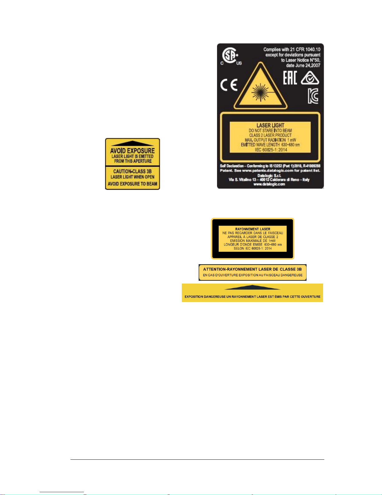
Warning labels indicating exposure to laser light and the device classification are applied
onto the body of the scanner.
Page 8
viii
Disconnect the power supply when opening the
device during maintenance or installation to avoid
exposure to hazardous laser light.
The laser diode used in this device is classified as a
class 3B laser product according to EN 60825-1
regulations and as a Class IIIb laser product
according to CDRH regulations.
Any violation of the optic parts in particular can
cause radiation up to the maximum level of the laser
diode (60 mW at 630 to 680 nm).
Warning and Device Class Labels
Produit(s) conforme selon 21CFR
1040.10 sauf des dérogations relatives
à la Laser Notice N° 50, date Juin 24,
2007.
Dans le paquet il y a l’étiquette(s) pour
les pays où le texte d'avertissement en
français sont obligatoires. Le(s) mettre
sur le produit à la place de la version
anglaise.
Exemple d'étiquettes d'avertissement laser
POWER SUPPLY
This product is intended to be installed by Qualified Personnel only.
This product is intended to be connected to a UL Listed or CSA Certified Power Unit marked
LPS or “Class 2”.
Page 9

ix
FCC COMPLIANCE
Modifications or changes to this equipment without the expressed written approval of
Datalogic could void the authority to use the equipment.
This device complies with PART 15 of the FCC Rules. Operation is subject to the following
two conditions: (1) This device may not cause harmful interference, and (2) this device must
accept any interference received, including interference which may cause undesired
operation.
This equipment has been tested and found to comply with the limits for a Class A digital
device, pursuant to part 15 of the FCC Rules. These limits are designed to provide
reasonable protection against harmful interference when the equipment is operated in a
commercial environment. This equipment generates, uses, and can radiate radio frequency
energy and, if not installed and used in accordance with the instruction manual, may cause
harmful interference to radio communications. Operation of this equipment in a residential
area is likely to cause harmful interference in which case the user will be required to correct
the interference at his own expense.
CE COMPLIANCE
CE marking states the compliance of the product with essential requirements listed in the
applicable European directive. Since the directives and applicable standards are subject to
continuous updates, and since Datalogic promptly adopts these updates, therefore the EU
declaration of conformity is a living document. The EU declaration of conformity is available
for competent authorities and customers through Datalogic commercial reference contacts.
Since April 20th, 2016 the main European directives applicable to Datalogic products require
inclusion of an adequate analysis and assessment of the risk(s). This evaluation was carried
out in relation to the applicable points of the standards listed in the Declaration of Conformity.
Datalogic products are mainly designed for integration purposes into more complex systems.
For this reason it is under the responsibility of the system integrator to do a new risk
assessment regarding the final installation.
Warning
This is a Class A product. In a domestic environment this product may cause radio
interference in which case the user may be required to take adequate measures.
EAC COMPLIANCE
Customs Union:
The CU Conformity certification has been achieved; this allows the Product to bear the
Eurasian mark of conformity.
BUREAU OF INDIAN STANDARD (BIS)
Self Declaration – Conforming to IS 13252 (Part 1):2010, R-41009288.
Page 10

x
HANDLING
The DS5100 is designed to be used in an industrial environment and is built to withstand
vibration and shock when correctly installed, however it is also a precision product and
therefore before and during installation it must be handled correctly to avoid damage.
avoid that the scanners hit one another causing damage. They should be handled
separately.
avoid that the scanners are dropped (exceeding shock limits).
do not fine tune the positioning by striking the scanner or bracket.
Page 11
xi
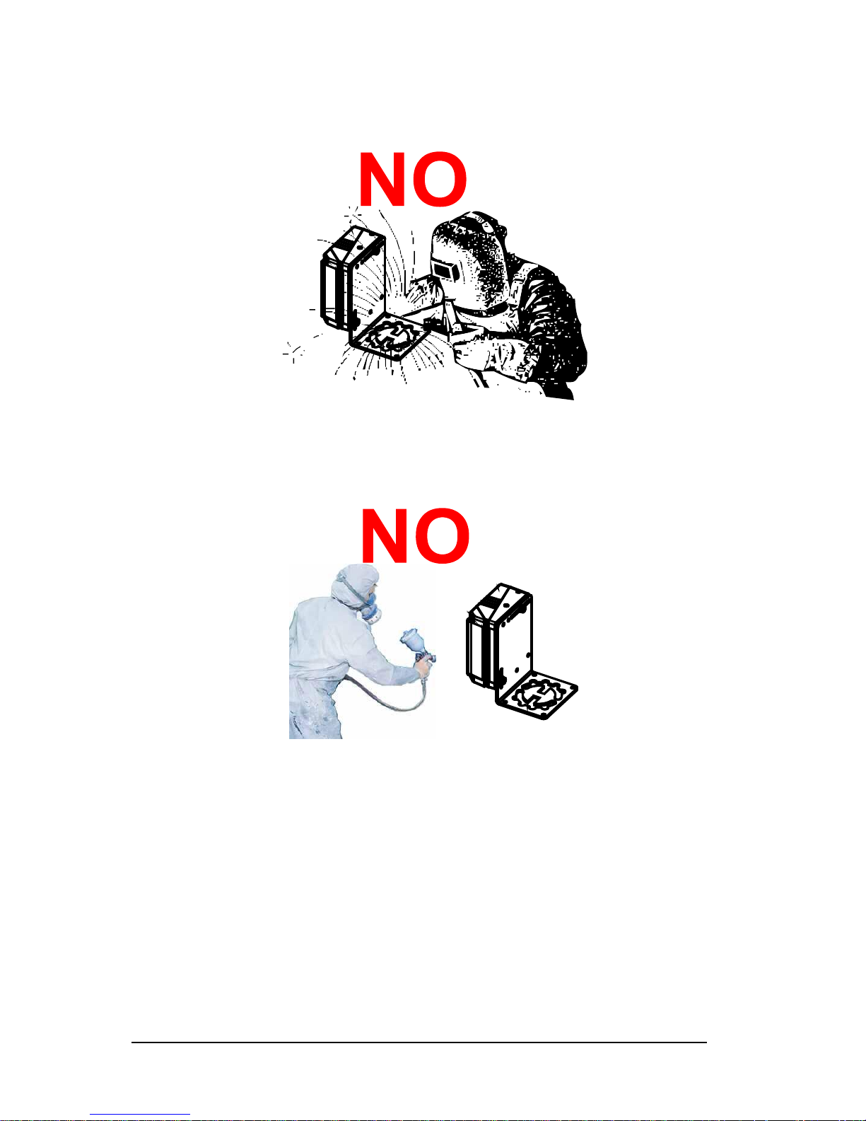
do not weld the scanner into position which can cause electrostatic, heat or output
window damage.
do not spray paint near the scanner which can cause output window damage.
Page 12
xii
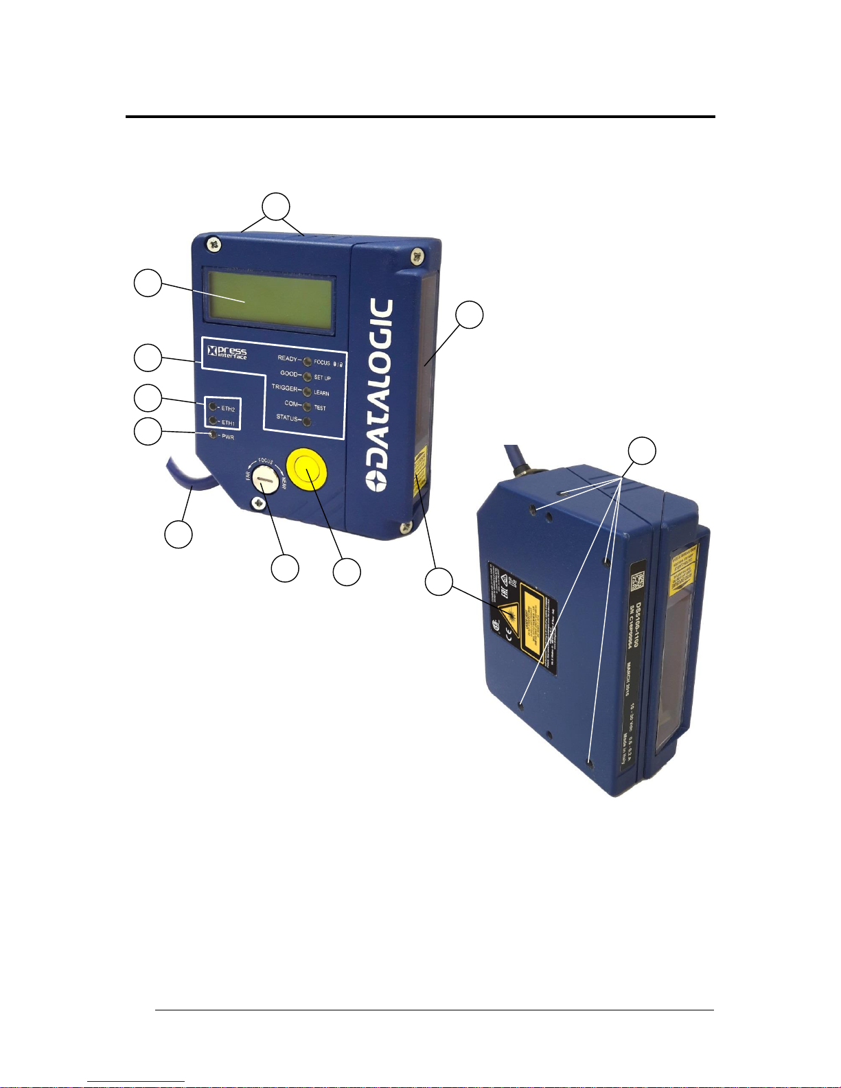
GENERAL VIEW
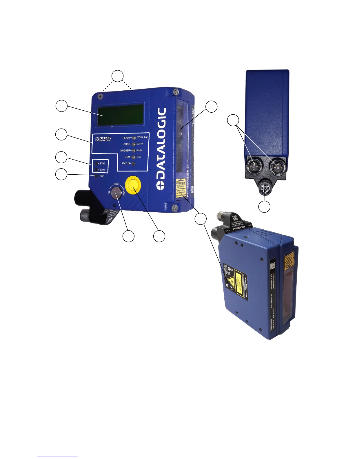
DS5100-X200
Serial Models
Figure A
1
Warning and Device Class Labels
7
Indicator LEDs
2
Power – Serial Interfaces – I/O Cable
8
Network LEDs
with 25-pin D-sub connector
9
Power On LED
4
Laser Beam Output Window
10
Focus Adjustment Screw
5
Mounting Holes (7)
11
X-PRESS™ Push Button
6
Display
10
11
2
4
7
9 8 6
5
1
5
Page 13

xiii
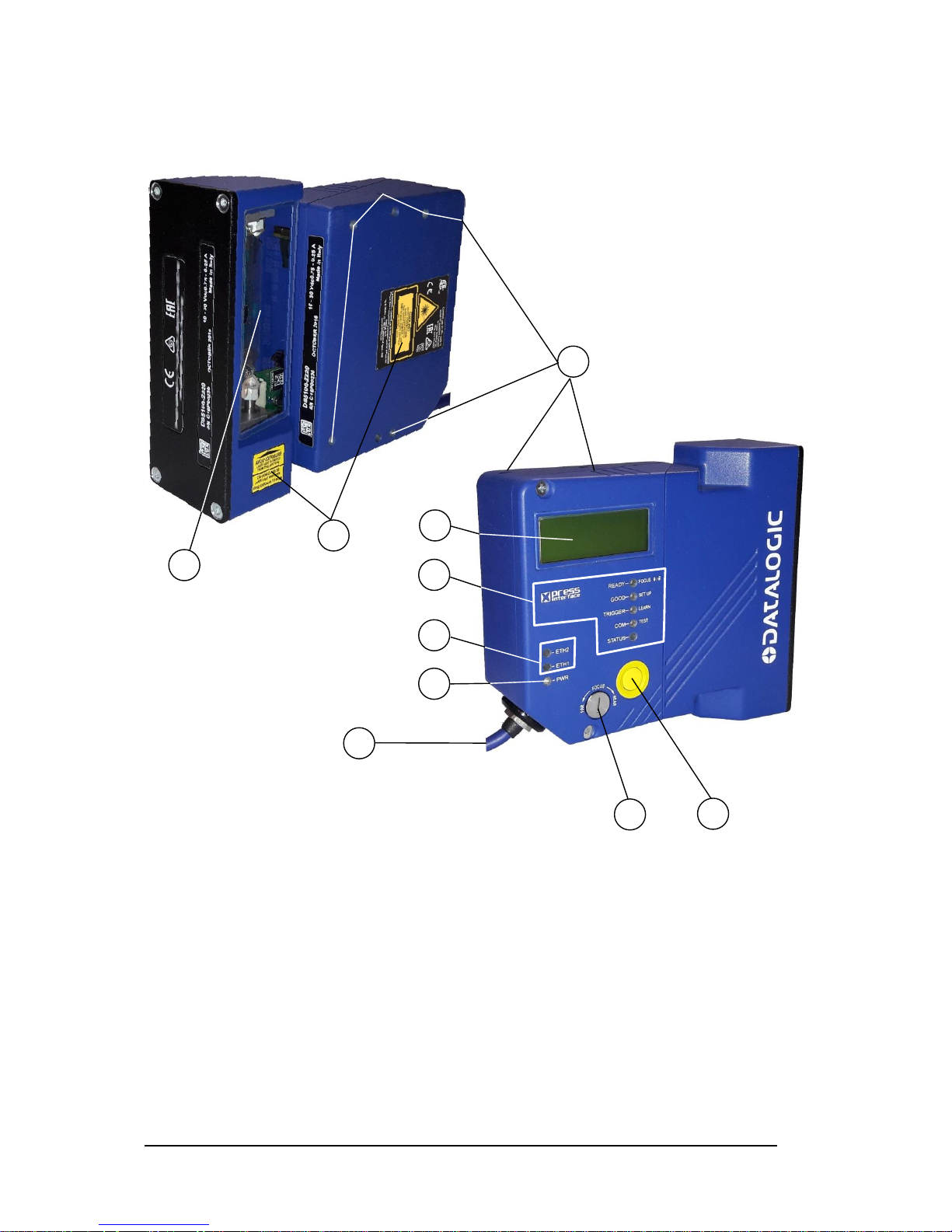
DS5100-X300
Built-in Ethernet Models
Figure B
1
Warning and Device Class Labels
7
Indicator LEDs
2
Power – Serial Interfaces – I/O Connector
8
Network LEDs
3
Ethernet Connector
9
Power On LED
4
Laser Beam Output Window
10
Focus Adjustment Screw
5
Mounting Holes (7)
11
X-PRESS™ Push Button
6
Display
Connector block rotates to 90° position.
9
6
10
11
8
2 4 5
7
1
3
5
Page 14
xiv
DS5100-X400
Profinet-IO Models
Figure C
1
Warning and Device Class Labels
7
Indicator LEDs
2
Power – Trigger Input Connector
8
Network LEDs
3
Profinet-IO – EBC Network Connectors
9
Power On LED
4
Laser Beam Output Window
10
Focus Adjustment Screw
5
Mounting Holes (7)
11
X-PRESS™ Push Button
6
Display
Connector block rotates to 90° position.
2
4
11
1
3
6
7 8 9
10
5
Page 15
xv
DS5100-XX20
OM Models
Figure D
1
Warning and Device Class Labels
7
Indicator LEDs
2
Power – Serial Interfaces – I/O Cable
8
Network LEDs
with 25-pin D-sub connector
9
Power On LED
4
Laser Beam Output Window
10
Focus Adjustment Screw
5
Mounting Holes (7)
11
X-PRESS™ Push Button
6
Display
4
1
6
7
8
9
11
10
2
5
Page 16
xvi
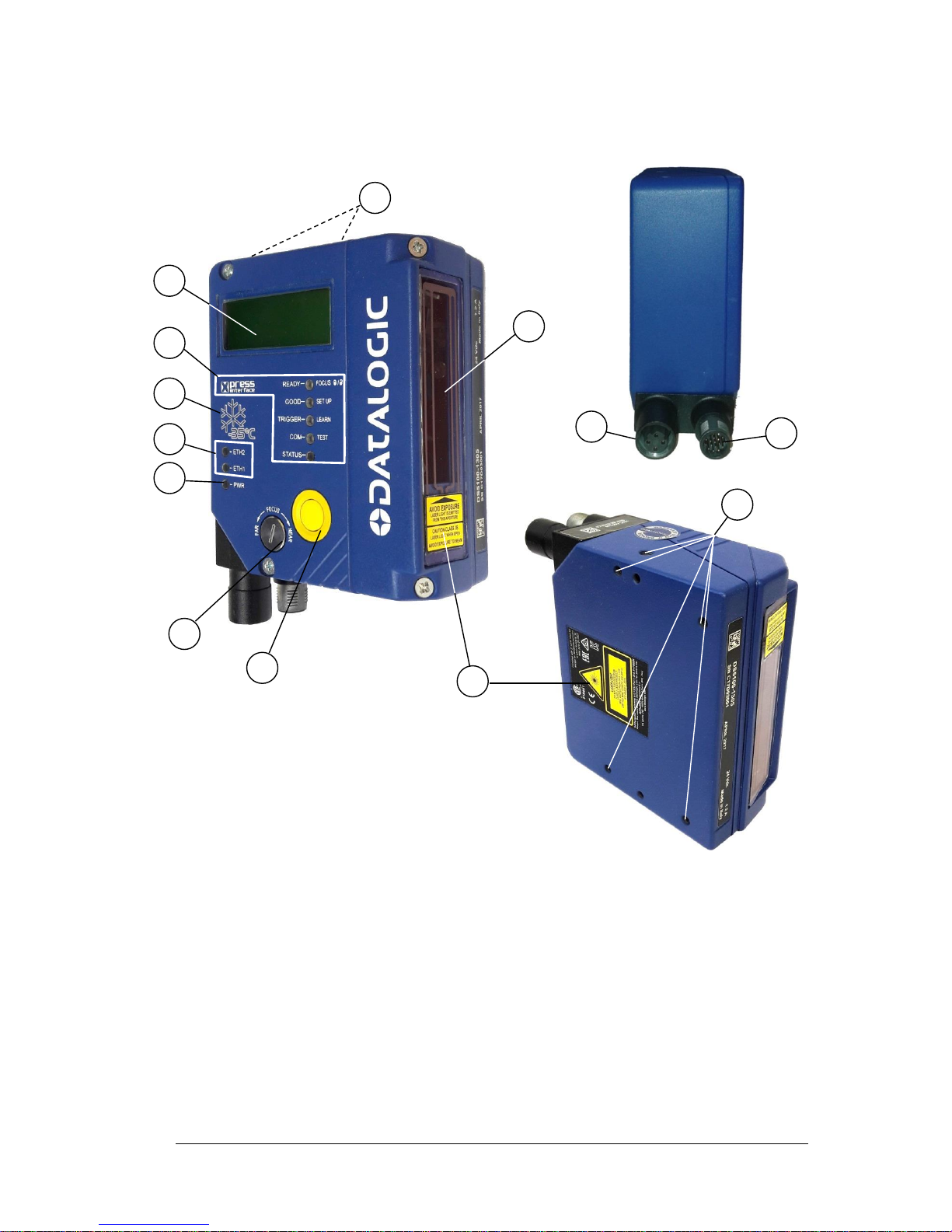
DS5100-XX05
Subzero™ Models
Figure E
1
Warning and Device Class Labels
7
Indicator LEDs
2
Power – Serial Interfaces – I/O Connector
8
Network LEDs
3
Ethernet Connector
9
Power On LED
4
Laser Beam Output Window w/ heater
10
Focus Adjustment Screw
5
Mounting Holes (7)
11
X-PRESS™ Push Button
6
Display
12
Subzero™ Logo
Connector block rotates to 90° position.
9
10
11
12
2
4
5
7
3
5
6
1
8
Page 17
RAPID CONFIGURATION
1
1
1 RAPID CONFIGURATION
NOTE: This chapter illustrates a Stand Alone application. For other types of
installations, such as ID-NET, Fieldbus, Pass-Through layouts, etc., refer to
chapters 4, and 5. For complete scanner configuration using the Genius
configuration program, refer to the Context-Sensitive Help On-Line.
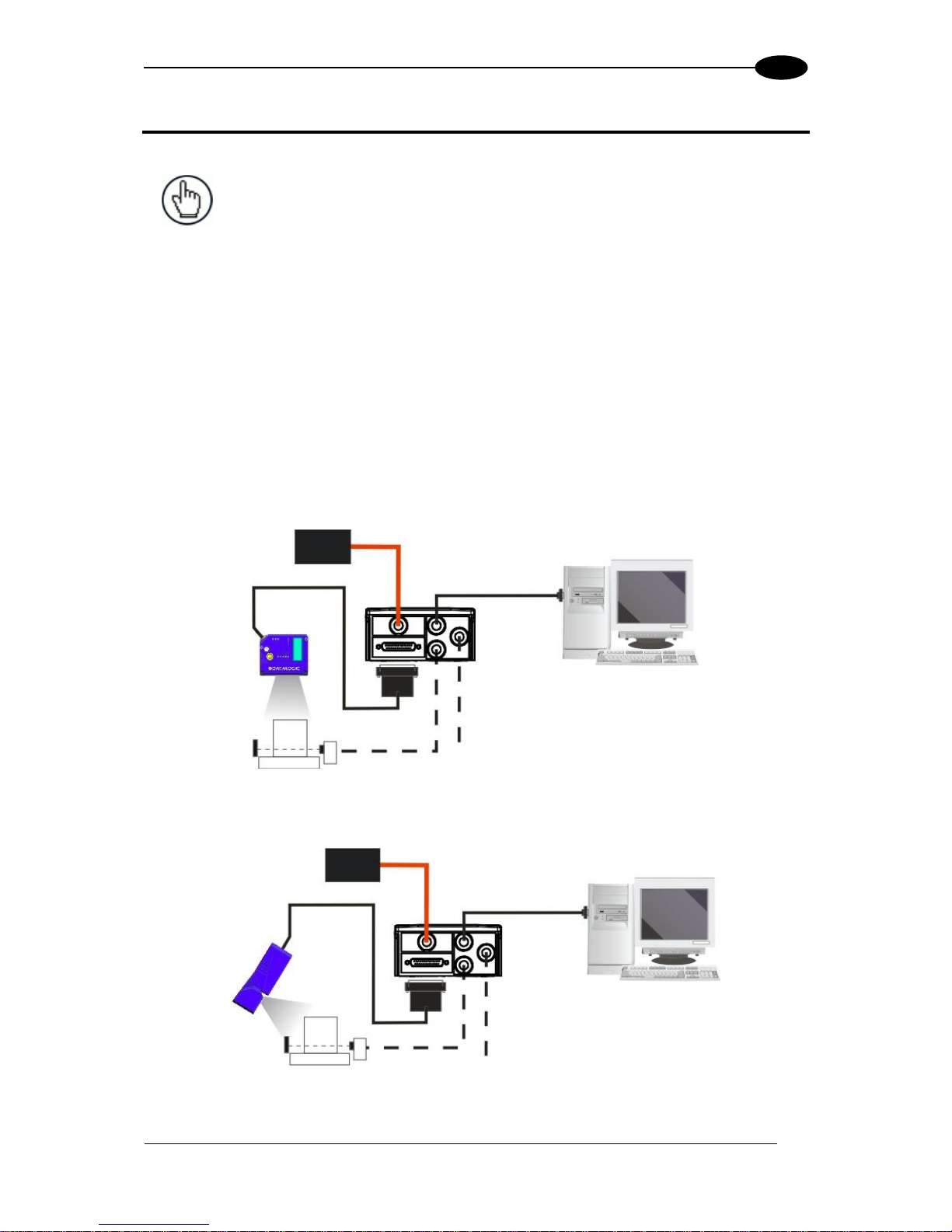
STEP 1 – CONNECT THE SYSTEM
To connect the system in a Stand Alone configuration, you need the hardware indicated in
Figure 1.
In this layout the data is transmitted to the Host on the main serial interface.
In Local Echo communication mode, the RS232 auxiliary interface can be used to transmit
data independently from the main interface selection.
When On-Line Operating mode is used, the scanner is activated by an External Trigger
(photoelectric sensor) when the object enters its reading zone.
Figure 1 – Scanner Connected to a Serial Host in a Stand Alone Layout
Figure 2 – OM Model Scanner Connected to a Serial Host in a Stand Alone Layout
DS5100
Host
PG 6000
P.S.*
* Presence Sensor
(for On-Line mode)
CBX100/500
I/O, AUX
MAIN
DS5100 OM
Host
PG 6000
P.S.*
* Presence Sensor
(for On-Line mode)
CBX100/500
I/O, AUX
MAIN
Page 18
DS5100 REFERENCE MANUAL
2
1
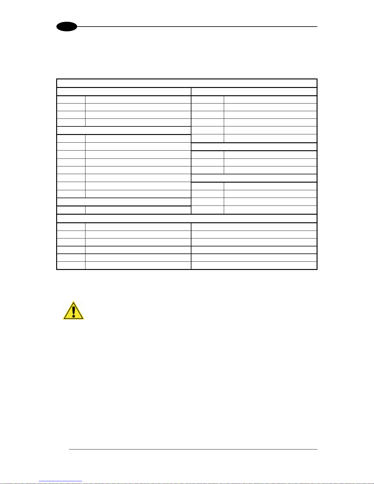
CBX100/500 Pinout for DS5100
The table below gives the pinout of the CBX100/500 terminal block connectors. Use this
pinout when the DS5100 reader is connected by means of the CBX100/500:
CBX100/500 Terminal Block Connectors
Input Power
Outputs
Vdc
Power Supply Input Voltage +
+V
Power Source - Outputs
GND
Power Supply Input Voltage -
-V
Power Reference - Outputs
Earth
Protection Earth Ground
O1+
Output 1 +
O1-
Output 1 -
Inputs
O2+
Output 2 +
+V
Power Source – External Trigger
O2-
Output 2 -
I1A
External Trigger A (polarity insensitive)
Auxiliary Interface
I1B
External Trigger B (polarity insensitive)
TX
Auxiliary Interface TX
-V
Power Reference – External Trigger
RX
Auxiliary Interface RX
+V
Power Source – Inputs
SGND
Auxiliary Interface Reference
I2A
Input 2 A (polarity insensitive)
ID-NET
I2B
Input 2 B (polarity insensitive)
REF
Network Reference
-V
Power Reference – Inputs
ID+
ID-NET network +
Shield
ID-
ID-NET network -
Shield
Network Cable Shield
Main Interface
RS232
RS485 Full-Duplex
TX
TX+
RTS
TX-
RX
*RX+
CTS
*RX-
SGND
SGND
* Do not leave floating, see par. 4.2.2 for connection details.
CAUTION: Do not connect GND, SGND and REF to different (external)
ground references. GND, SGND and REF are internally connected through
filtering circuitry which can be permanently damaged if subjected to voltage
drops over 0.8 Vdc.
Page 19

RAPID CONFIGURATION
3
1
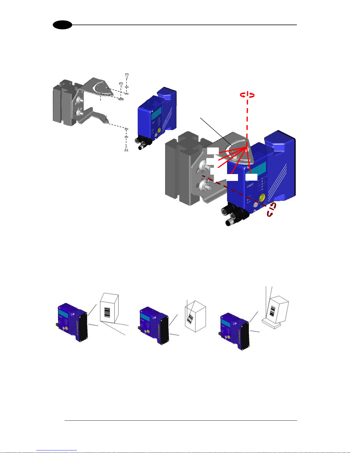
STEP 2 – MOUNT AND POSITION THE SCANNER
DS5100 Standard and Subzero Models
1. To mount the scanner, use the mounting bracket to obtain the most suitable position for
the reader as shown in the figures below.
Figure 3 - Positioning with Mounting Bracket
2. When mounting the scanner take into consideration these three ideal label position angles:
Skew 15° to 30°, Tilt 0° and Pitch 0°.
Assure at least 15° Minimize Minimize
Figure 4 –Skew, Tilt and Pitch Angles
3. Refer to the Reading Diagrams in par. 6.4 to decide the distance your scanner should be
positioned at.
Skew
-45° -15° 0° 15° 45°
Pitch
S
T
P
Page 20
DS5100 REFERENCE MANUAL
4
1
DS5100 OM Models
1. To mount the DS5100 OM, use the mounting bracket to obtain the most suitable position
for the reader as shown in the figures below.
Figure 5 - Positioning with Mounting Bracket
2. When mounting the DS5100 OM take into consideration these three ideal label position
angles: Skew 15° to 30°, Tilt 0° and Pitch 0°. The Skew angle refers to the most inclined
or external raster line, so that all other raster lines assure more than 15° Skew.
Assure at least 15° Minimize Minimize
Figure 6 –Skew, Tilt and Pitch Angles
3. Refer to the Reading Diagrams in par. 6.4 to decide the distance your scanner should be
positioned at.
S
T
P
Tilt
alignment marks
Skew
0°
45°
-45°
-15°
15°
Page 21

RAPID CONFIGURATION
5
1
STEP 3 – FOCUS THE SCANNER
The reading distance depends on the focus distance of the scanner and should be set
according to the application requirements. The Focus Position is set directly through the
focus adjustment screw on the front panel of the scanner. This screw moves the internal lens
of the scanner to change the focal point of the scanner. The setting is continuous but should
not be set beyond the limits "Too Far" or "Too Near" which appear on the display at the
extremes of the focus range. Although the scanner reads across the entire focus range, there
are three guaranteed positions which correspond to the reading diagrams in par. 6.4.
1. Power up the scanner. For Subzero models, At -35 °C, a 20-
minute warm-up period is required before the scanner is
ready to read barcodes, the Ready LED blinks. Wait for the
power up sequence to finish. By default the scanner focus is in
the Unlocked position. The alternating message on the display
shows the mechanical Focus Position as well as the message
“Please Lock Focus!” on the scanner display.
2. Using a screwdriver turn the focus adjustment screw in the
desired direction, clockwise (focus nearer to the scanner) or
counterclockwise (focus farther from the scanner). The focus
position in centimeters and inches is shown on the scanner
display.
NOTE: After correctly focusing the scanner, it is strongly recommended to store
the value of the Focus Position in memory (Locked Position parameter). When
Locked, if the mechanical position changes by more than the allowed tolerance
of the value in memory, a diagnostic alarm will be sent to the display. See the
Focus Lock function in step 4, X-PRESS Configuration.
As an additional visual aid during focusing, the indicator LEDs show the relative focus
position as follows:
Model
1xxx less than 30 cm
30 cm NEAR
32-38 cm
40 cm MEDIUM
2xxx
less than 45 cm
45 cm NEAR
47-63 cm
65 cm MEDIUM
Model
1xxx
42-58 cm
60 cm FAR
more than 60 cm
2xxx
67-73 cm
75 cm FAR
more than 75 cm
Page 22
DS5100 REFERENCE MANUAL
6
1
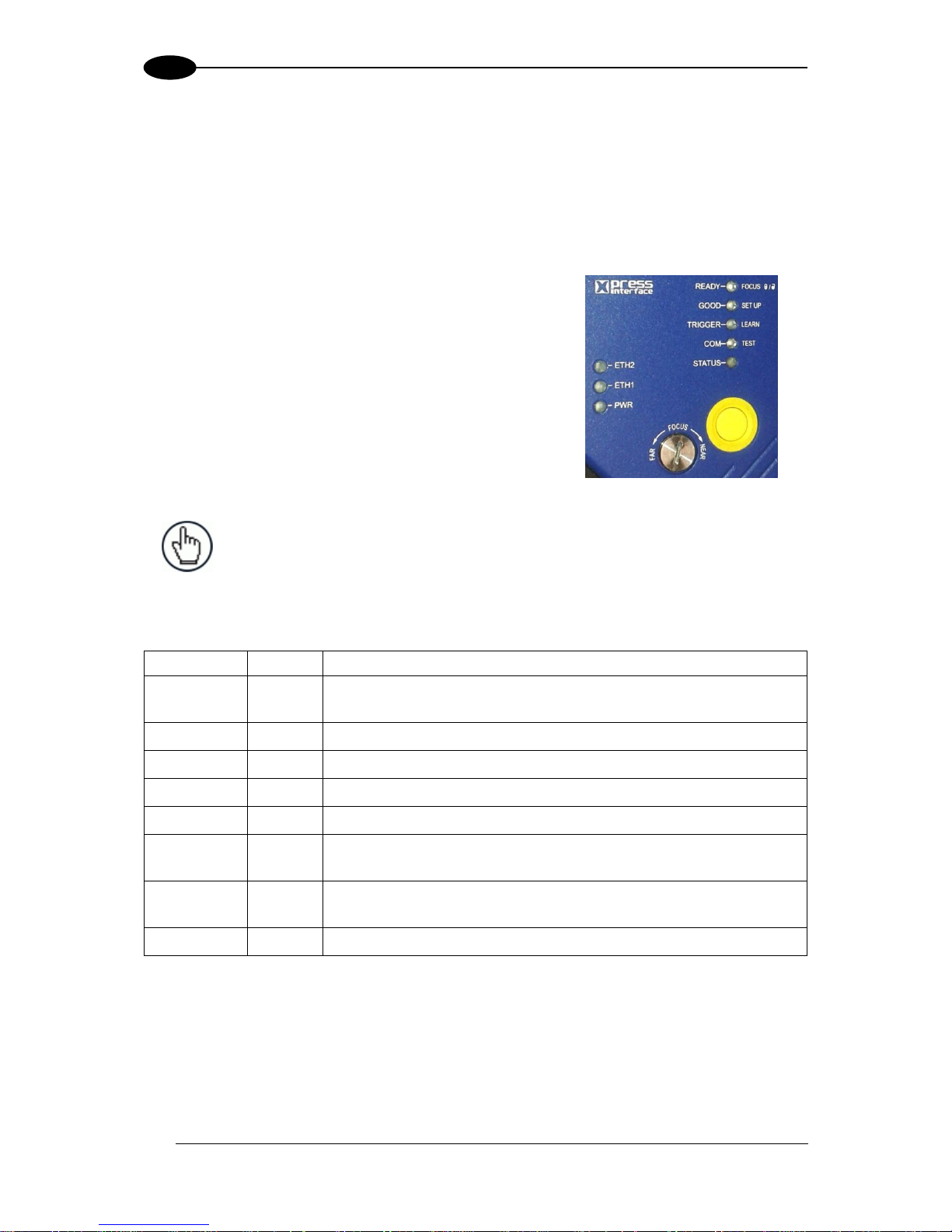
STEP 4 – X-PRESS CONFIGURATION
X-PRESS is the intuitive Human Machine Interface designed to improve ease of installation
and maintenance.
Status and diagnostic information are clearly presented by means of the colored LEDs,
whereas the single push button gives immediate access to the following relevant functions:
AutoSetup to self-optimize and auto-configure reading
performance in demanding applications
AutoLearn to self-detect and auto-configure for
reading unknown barcodes (by type and length)
Focus Lock to memorize the mechanical focus
position
Test Mode with bar graph visualization to check static
reading performance
EBC/Profinet-IO network selection to set the scanner
as a Slave in an EBC network. (only for on-board
Profinet 2 port models).
NOTE: When entering the X-PRESS interface on the DS5100-xx2x the
Oscillating Mirror remains in the default fixed position (0°) in order to make
barcode reading easier while performing the X-PRESS functions.
The colors and meaning of the indicator LEDs are illustrated in the following table:
LED
Color
Description
READY
Green
Indicates the device is ready to operate. For Subzero models this
LED blinks during the warm-up phase.
GOOD
Green
Confirms successful reading.
TRIGGER
Yellow
Indicates the status of the reading phase. *
COM
Yellow
Indicates active communication on main serial port. **
STATUS
Red
Indicates a NO READ result.
ETH2
Yellow
Indicates connection to the on-board Profinet-IO network port 2.
Not used on other models.
ETH1
Yellow
Indicates connection to the on-board Ethernet or on-board
Profinet-IO network port 1. Not used on Serial models.
PWR
Blue
Indicates that the reader is connected to the power supply.
* In On-Line mode the TRIGGER LED corresponds to the active reading phase signaled by the Presence Sensor.
In Automatic and Continuous modes the TRIGGER LED is always on indicating that the reader is ready to read a
code.
** When connected to a Fieldbus network through a Host Interface Module inside the CBX500 or through a QLM,
the COM LED is always active, even in the absence of data transmission, because of polling activity on the
Fieldbus network.
During the reader startup (reset or restart phase), the first five LEDs blink for one second.
Page 23
RAPID CONFIGURATION
7
1
Auto Learn
If you are configuring your scanner using X-PRESS, you must start with the Auto Learn
procedure.
1. Enter the Auto Learn function by holding the X-PRESS push button pressed until the
LEARN LED is on.
2. Release the button to enter the Auto Learn function.
Once entered, the reader starts a procedure to automatically detect and recognize
barcodes (by type and length), which are presented to it (*). The laser turns on and the
LEARN LED blinks to indicate the ongoing process.
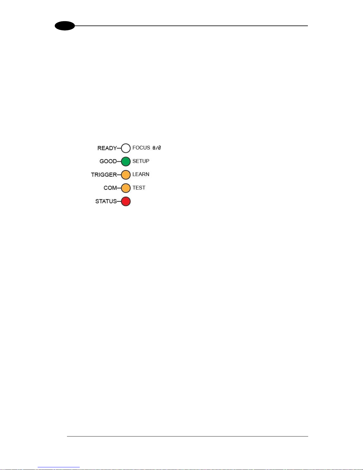
Figure 7 – X-PRESS Interface: Auto Learn Function
The procedure is as follows:
A) place the desired barcode on the
scanline.
B) wait until the LEARN LED stays
steady on (indicating the reader
has detected the barcode).
C) repeat, if needed, the above two
steps to program up to 10 different
barcodes (the LEARN LED returns
to the blinking state for the next
code). If more than one barcode is
detected in the scan line, the Multi
Label mode is enabled (refer to the
“5K Family Software Configuration
Parameter Guide” Help file).
3. Exit the process by pressing the X-PRESS push button once. The scanner will restart at
the end of the process, and then the detected barcodes are automatically configured in
scanner memory.
NOTE: If the barcode cannot be read because of low contrast or excessive
ambient light, you can perform the AutoSetup function to optimize the optical
parameters. Then you can perform AutoLearn to recognize the barcode
symbology.
NOTE: On exit from Autolearn, the following parameters are forced: Code
Combination = Single Label, Reading Mode = Linear. If necessary, these
parameters can be changed through Genius.
* In case of Programming Barcodes, refer to the “Setup Procedure Using Programming Barcodes” document in
the downloadable Genius mini-DVD zip file.
Page 24
DS5100 REFERENCE MANUAL
8
1
Auto Setup (Optional)
At the end of the Auto Learn procedure, you have the possibility to follow the Auto Setup
procedure to set up the reading parameters.
1. Enter the Auto Setup function by holding the X-PRESS push button pressed until the
SETUP LED is on.
2. Release the button to enter the Auto Setup function.
3. Once entered, if a barcode label is positioned in front of the scanline, the scanner
automatically performs the optimal setup of the reading parameters for that specific
barcode.
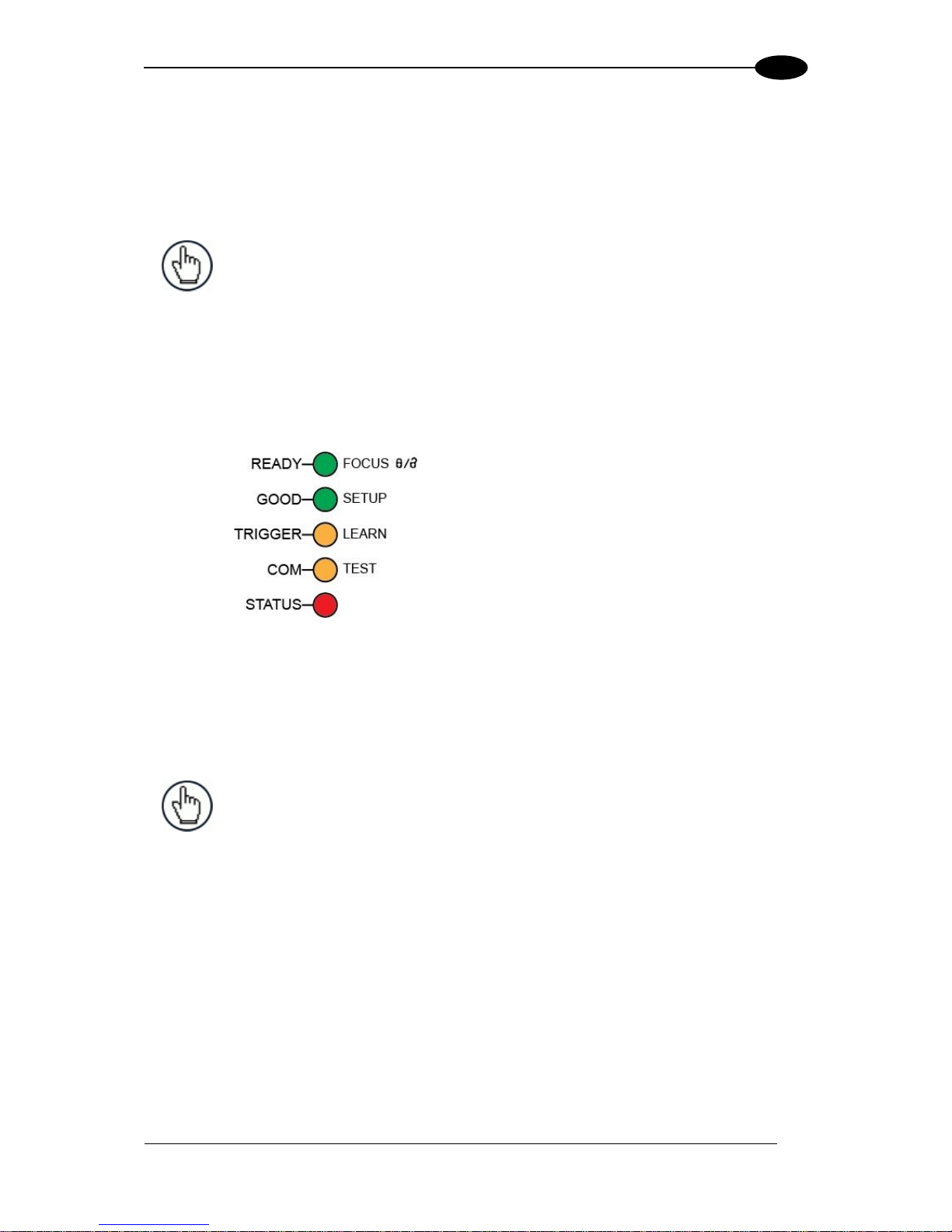
Figure 8 – X-PRESS Interface: Auto Setup Function
The procedure is as follows:
A) place the desired barcode on
the scanline.
B) enter the AutoSetup function
(the laser turns on and the
SETUP LED blinks to indicate
the ongoing process)
C) wait until the SETUP LED
stays steady on (indicating the
reader has detected the
barcode)
This procedure ends either when the barcode is successfully decoded or after a timeout of
about 7 (seven) seconds.
The scanner will restart at the end of the process, and then the optimized reading
parameters for that barcode are automatically configured in scanner memory.
Page 25
RAPID CONFIGURATION
9
1
Focus Lock/Unlock
You must perform the Focus Lock procedure to save the mechanical focus position to
memory. When Locked, if the mechanical focus position is changed by more than the
allowed tolerance of the value in memory, a diagnostic alarm will be sent to the display. See
par. 2.3.1 for details.
NOTE: For Stand Alone or Master devices, the diagnostic alarm can also be
sent to any of the desired communication channels by selecting it in the
Diagnostic>Actions branch of the Genius configuration tool.
1. Enter the Focus Lock function by holding the X-PRESS push button pressed until the
FOCUS LOCK LED is on.
2. Release the button to enter the Focus Lock function.
Once entered, the scanner automatically performs the Lock (saving) or Unlock procedure
depending on the previous state of the Locked Position parameter.
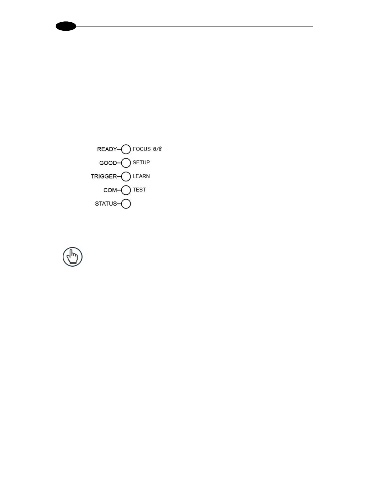
Figure 9 – X-PRESS Interface: Focus Lock/Unlock
Function
The procedure is as follows:
A) enter the Focus Lock function
B) wait until the "Focus locked at..."
message appears on the display
(indicating the focus position has
been saved to memory). The
following parameters are set:
Locked Position = your mechanical
setting
Focus Displacement (Alarm) = set
(default to display only)
The scanner will be reset at the end of the process. The LEDs turn off, the Display goes
blank and then the Ready LED will turn on indicating the scanner is ready.
NOTE: If your application has been configured using X-PRESS, go to
STEP 6.
Page 26
DS5100 REFERENCE MANUAL
10
1
EBC/Profinet-IO Network Selection (only on Profinet-IO dual port models)
For on-board Profinet 2 port models, the DS5100 scanner can be configured to work as a
Slave in an EBC network. The only way to make this selection is through the X-PRESS
button.
1. Enter the EBC/Profinet-IO Network Selection function by holding the X-PRESS push button
pressed until the all X-PRESS LEDs are off.
2. Release the button to enter the Network Selection function.
Once entered, the scanner automatically performs the procedure to set itself as either an
EBC slave or a Profinet-IO slave depending on the previous state of the network
selection.
Figure 10 – X-PRESS Interface: EBC/Profinet-IO Network
Selection Function
The procedure is as follows:
A) enter the Network selection function.
B) wait until the "EBC Slave" o
“Profinet-IO” message appears on
the display (indicating the scanner
has been set and saved.
The scanner will restart at the end of the process.
NOTE: To reset the scanner to its default Profinet interface settings, you can
also perform the Reset Scanner to Factory Default procedure as described in
the paragraph below.
Reset Scanner to Factory Default (Optional)
If it ever becomes necessary to reset the scanner to the factory default values, you can
perform this procedure by holding the X-PRESS push button pressed while powering up the
scanner and waiting for all the X-PRESS LEDs to blink simultaneously three times before
releasing the push button.
This procedure takes ≈ 5-6 seconds for Serial Models, ≈ 10 seconds for Ethernet Models, ≈
20 seconds for 2 port Profinet-IO models. At the end of the procedure the Configuration and
Environmental parameters are reset and the message "Default Set" is shown on the scanner
display. If connected through a CBX500 with BM150 display module, the "Default Set"
message is also shown on the CBX500 display.
Page 27
RAPID CONFIGURATION
11
1
STEP 5 – INSTALL GENIUS CONFIGURATION PROGRAM
Genius is a Datalogic scanner configuration tool providing several important advantages:
Wizard approach for new users;
Multi-language version;
Defined configuration directly stored in the reader;
Communication protocol independent from the physical interface allowing to consider
the reader as a remote object to be configured and monitored.
To install Genius, on the PC that will be used for configuration, (running Windows XP,
or 7), download the Genius mini-DVD .zip file. Extract the files to a local folder and
launch the Setup.exe file. Select Install Genius and follow the installation procedure.
This configuration procedure assumes scanner connection to a CBX100/500. Genius,
running on a laptop computer, is connected to the scanner auxiliary port through the
CBX100/500 9-pin connector. To communicate with the scanner, Genius performs an auto
baudrate detection starting from its default parameters which are 115200, 8, N, 1. These
parameters can also be set in the Genius Tools>Options>Communications window.
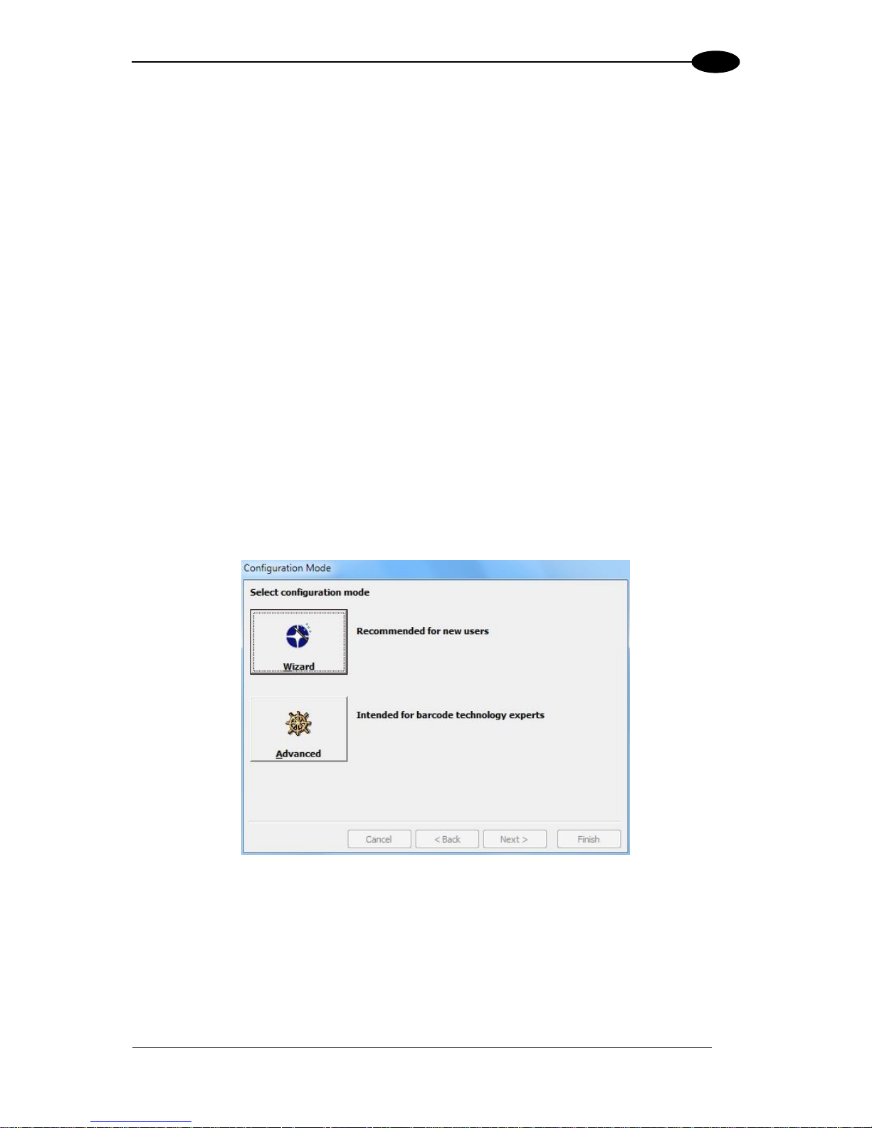
Wizard for Quick Reader Setup
After installing the Genius software program the following window appears asking the user to
choose the desired configuration level.
Figure 11 - Genius Wizard Opening Window
The Wizard option is advised for rapid configuration or for new users, since it shows a stepby-step scanner configuration.
Page 28

DS5100 REFERENCE MANUAL
12
1
1. Select the Create a new configuration button.
You will be guided through the configuration being asked to define the following
parameters:
a. Barcode selection and definition
Page 29
RAPID CONFIGURATION
13
1
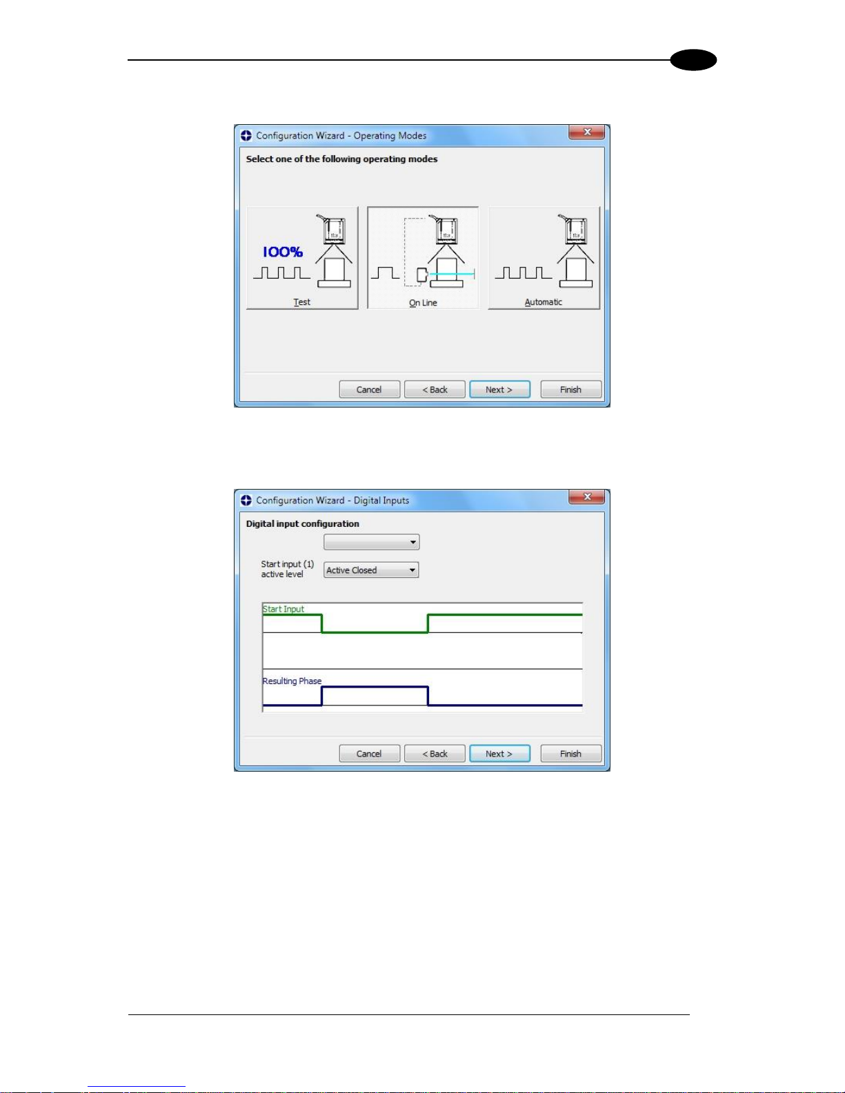
b. Operating mode selection and definition
a. Digital Inputs configuration
Page 30
DS5100 REFERENCE MANUAL
14
1
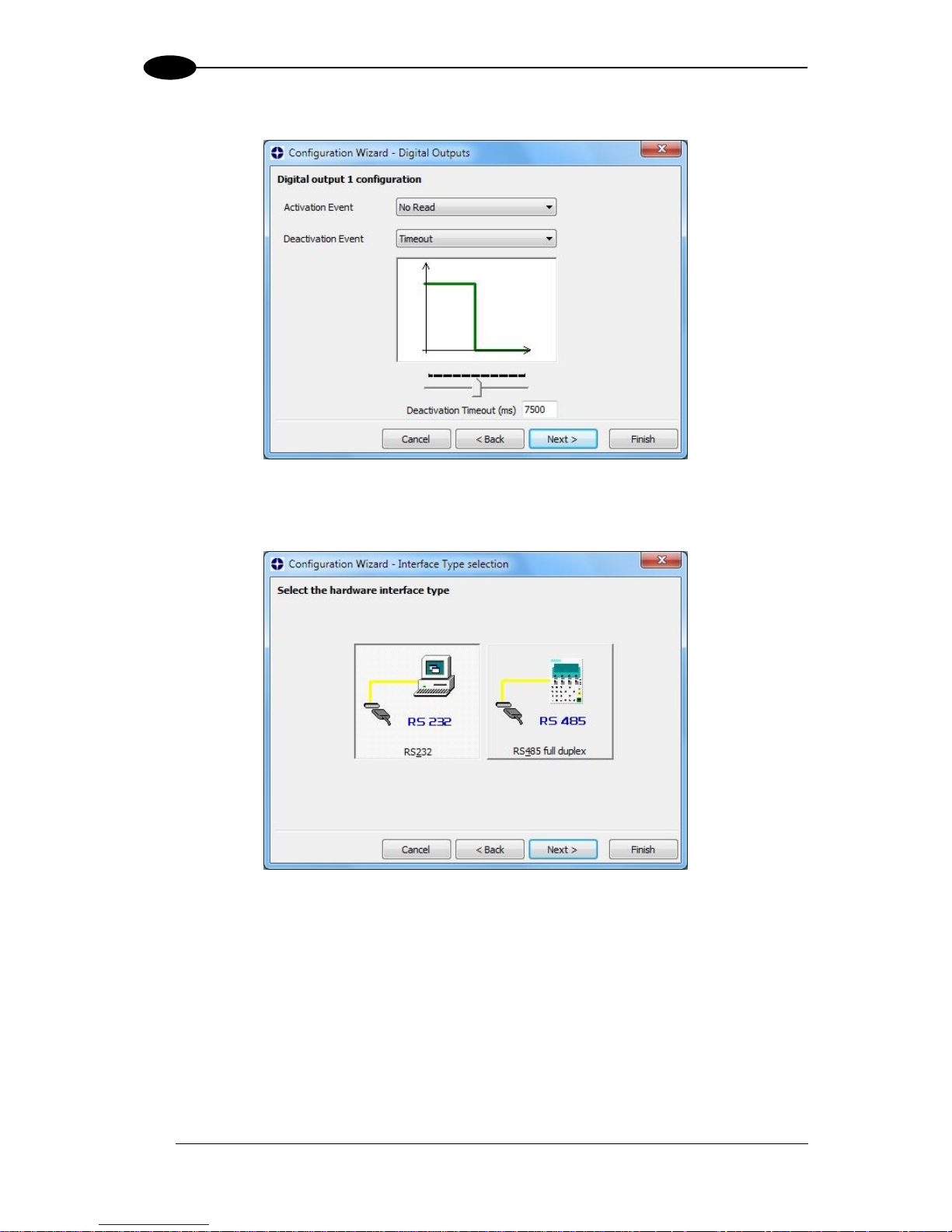
b. Digital Outputs configuration
c. Hardware interface selection
Page 31

RAPID CONFIGURATION
15
1
d. Output data format configuration
The On Line operating Mode requires the reader to be connected to an External
Trigger/Presence Sensor using I1A and I1B inputs.
The Automatic operating mode does not require connection to an external Presence
Sensor. When working in this mode the reader is continuously scanning, while the
reading phase is activated each time a barcode enters the reader reading zone. The
reader stops reading after an N number of scans without a code. Barcode characters
are transmitted on the serial interface. In case of a failed reading phase no message is
sent to the host computer.
Page 32

DS5100 REFERENCE MANUAL
16
1
2. After defining the parameter values the following window appears allowing to complete
the reader configuration as follows:
Saving the configuration to disk;
Switching to Advanced mode;
Sending the configuration to the scanner.
3. After sending the configuration to the
scanner you have completed the
configuration process.
4. By clicking Finish, the System
Information window will be displayed
with specific information concerning the
scanner.
Page 33

RAPID CONFIGURATION
17
1
STEP 6 – TEST MODE
NOTE: When entering the X-PRESS interface on the DS5100-XX2X the
Oscillating Mirror remains in the default fixed position (0°) in order to make
barcode reading easier while performing the X-PRESS functions.
Use a code suitable to your application to test the system. Alternatively, you can use the
Datalogic Test Chart (Code 128).
1. Enter the Test mode function by holding the X-PRESS push button pressed until the
TEST LED is on.
2. Release the button to enter the Test mode function.
Once entered, the Bar-Graph on the five LEDs is activated and if the scanner starts
reading barcodes the Bar-Graph shows the Good Read Rate. In case of no read
condition, only the STATUS LED is on and blinks.
Figure 12 – X-PRESS Interface: Test Mode Function
3. To exit the Test Mode, press the X-PRESS push button once.
NOTE: By default, the Test Mode exits automatically after two minutes.
Page 34

DS5100 REFERENCE MANUAL
18
1
ADVANCED SCANNER CONFIGURATION
The ADVANCED configuration mode (instead of the Wizard) is available when starting the
Genius program and is addressed to expert users being able to complete a detailed scanner
configuration. By choosing this option it is possible either to start a new scanner configuration
or to open and modify an old one. The desired parameters can be defined in the following
window, similar to the MS Explorer:
Figure 13 - Genius Parameter Explorer Window
Host Mode Programming
The scanner can also be configured from a host computer using the Host Mode
programming procedure, by commands via the serial interface. See the Host Mode
Programming manual on the downloadable Genius mini-DVD zip file.
Alternative Layouts
The ID-NET network is a built-in high-speed interface dedicated for high-speed scanner
interconnection. ID-NET is in addition to the Main and Auxiliary serial interfaces. If you
need to install an ID-NET network refer to chapters 4 and 5 of this Reference Manual.
The scanner can also be configured by reading programming barcodes. See the "Setup
Procedure Using Programming Barcodes" printable from the downloadable Genius miniDVD zip file.
If you need to install an Ethernet network, Fieldbus network or Pass-Through network,
refer to chapters 4 and 5 of this Reference Manual.
Page 35

INTRODUCTION
19
2
2 INTRODUCTION
2.1 PRODUCT DESCRIPTION
The DS5100 laser scanner satisfies the most advanced needs of a wide range of users. It
has been developed focusing on the realistic requirements of its target market. The
outstanding result is an extremely compact, cost-effective and easy to use industrial scanner.
Standard Application
Program
A standard application program is factory-loaded onto the
scanner. This program controls barcode reading, serial port
interfacing, data formatting and many other operating and control
parameters.
It is completely configurable from a host computer through the
Genius utility program provided on the downloadable Genius
mini-DVD zip file, or via the serial interface (Genius based Host
Mode Programming).
Custom Application
Programs
If the Standard Application Program does not meet your
requirements, please contact your local Datalogic distributor.
Some of the main features are listed below:
Medium, Long Range, Linear and Oscillating Mirror models, user selectable focus for
high application flexibility
ID-NET™ and EBC™ (Ethernet Bus Connections)
Embedded PROFINET-IO and EtherNet/IP for connectivity to main industrial Fieldbus
X-PRESS™ interface, Genius™ software tool, embedded multi-language display for easy
scanner setup and maintenance
Rotating connector block for flexible form factor and easy installation
DST™ (Digital Signal Technology)
ACR4™ reconstruction technology
PackTrack™ (only for Long Range models working in EBC)
Superior ambient light immunity from high frequency laser modulation
Top industrial grade, IP65 and Subzero™ version for low temperature environments
The scanner uses a solid-state laser diode as a light source; the light emitted has a
wavelength between 630 and 680 nm. Refer to the section “Safety Precautions” at the
beginning of this manual for information on laser safety.
The protection class of the enclosure is IP65, the reader is therefore suitable for industrial
environments where high protection against harsh external conditions is required.
Page 36

DS5100 REFERENCE MANUAL
20
2
2.1.1 Indicators
The five LEDs on the side of the scanner (Figure A, B, C, D, E, 7) indicate the following:
LED
Color
Description
READY
Green
This LED indicates the device is ready to operate. For Subzero
models this LED blinks during the warm-up phase.
GOOD
Green
This LED confirms successful reading.
TRIGGER
Yellow
This LED indicates the status of the reading phase. *
COM
Yellow
This LED indicates active communication on main serial port. **
STATUS
Red
This LED indicates a NO READ result.
* In On-Line mode the TRIGGER LED corresponds to the active reading phase signaled by the Presence Sensor.
In Automatic and Continuous modes the TRIGGER LED is always on indicating that the reader is ready to read a
code.
** When connected to a Fieldbus network through the CBX500, the COM LED is always active, even in the
absence of data transmission, because of polling activity on the Fieldbus network.
During the reader startup (reset or restart phase), all the LEDs blink for one second.
PWR (blue)
This LED indicates that the reader is connected to the power
supply.
ETH (yellow)
This LED indicates connection to the on-board Ethernet or
Profinet-IO network.
2.2 ID-NET
The ID-NET network is a built-in high-speed interface dedicated for
high-speed scanner interconnection. ID-NET is in addition to the
Main and Auxiliary serial interfaces.
The following network configurations are available:
ID-NET Synchronized: Single station – multiple scanners
ID-NET interface allows local connection of
multiple scanners reading different sides of
the same target. All scanners share a
single presence sensor and
activate/deactivate simultaneously.
At the end of each reading phase a single
data message is transmitted to the host.
Thanks to ID-NET, data communication
among scanners is highly efficient so that
an immediate result will be available.
Page 37

INTRODUCTION
21
2
ID-NET Multidata: Multiple stations – single scanner
ID-NET interface allows connection of scanners reading objects placed on independent
conveyors. All scanners are typically located far away from each other and they use a
dedicated presence sensor.
At the end of each reading phase, each scanner transmits its own data message to the host.
Thanks to ID-NET, data collection among readers is accomplished at a high speed without
the need of an external multiplexing device. This leads to an overall cost reduction and to a
simple system wiring.
Page 38

DS5100 REFERENCE MANUAL
22
2
2.2.1 How To Setup/Configure the Scanner Network
A complete ID-NET scanner network can be rapidly setup, as follows:
Mounting & Connection
1. Mechanically mount/install all the readers (refer to par. 3.2 and 3.3).
2. Wire ID-NET (refer to par. 4.3).
3. Connect the planned Master scanner to a PC by means of the Genius configuration
software.
4. Power up the entire system.
Configuration
1. Launch Genius.
2. From the Genius Device Menu select “Local Device Network Settings” and program the
Role of the Master scanner (Synchronized or Multidata).
This procedure requires the Network Baud Rate be the same for all Slaves and Master,
(500 kbs is the default value). It can be changed after network setup using Genius
through the Master scanner. See also the alternative procedure in the note below.
3. At the prompt to "Send updated Network configuration to the Local Device" (Master)
choose "Yes".
4. Then run the NET-AUTOSET procedure from the Icon in the Devices Area. Genius sets
all slave scanners according to the Master Role (Synchronized or Multidata), and assigns
each a random address. If necessary, this address can be changed through the Network
Wizard.
5. Configure the System parameters via Genius.
6. If using the CBX connection box equipped with a BM100 Backup module, perform
System Backup at the Master. See par. 2.4 of this manual or the BM100 or BM150
manuals for details.
The scanner network is ready.
NOTE: If necessary, the ID-NET baudrate can be set individually on each
Slave scanner to match the Master. Connect each Slave to Genius and set the
Reading System Layout > Network Baudrate parameter. Then follow the
procedure above.
NOTE: An alternative method of programming scanner address and role
assignment can be accomplished by using the "Connectivity Programming
Barcodes" (refer to the "Setup Procedure Using Programming Barcodes"
document on the downloadable Genius mini-DVD zip file.).
Page 39

INTRODUCTION
23
2
2.3 X-PRESS HUMAN MACHINE INTERFACE
X-PRESS is the intuitive Human Machine Interface
designed with the precise goal of improving ease of
installation and maintenance.
Status and diagnostic information are clearly presented
by means of five-colored LEDs, whereas the single
multi-function key gives immediate access to relevant
functions:
Autosetup to self-optimize reading performance in
demanding applications
Autolearn to self-detect unknown barcodes
Focus Lock to memorize the mechanical focus
position
Test Mode with bar-graph visualization to check
static reading performance
X-PRESS is the common interface adopted in all new products: “You learn one, you can use
them all”.
The colors and meaning of the five LEDs when in the one of the operating modes (On-Line,
Automatic or Continuous) are illustrated in par 2.1.1.
NOTE: Except for the Focus Lock/Unlock function, the X-PRESS functions do
not work if the motor or laser are turned off, see chp. 8 for details.
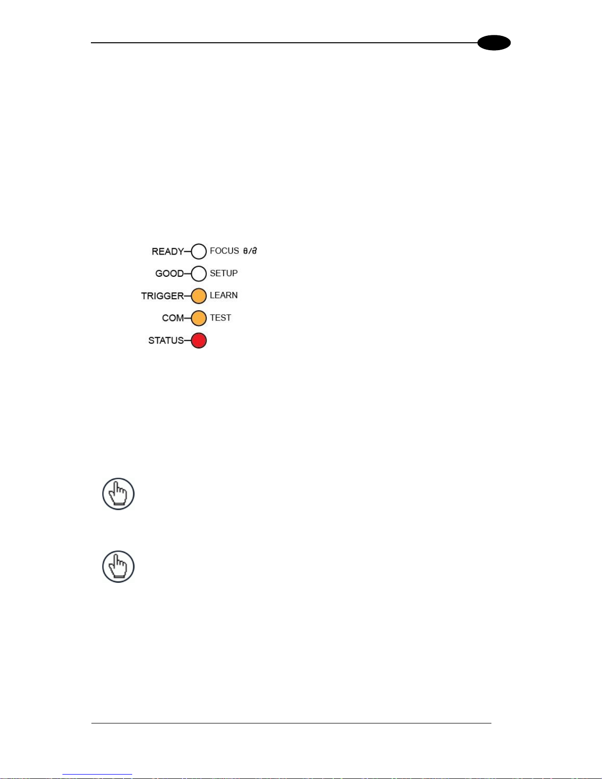
2.3.1 Diagnostic Indication
The “STATUS” and “READY” LEDs blink simultaneously to signal the presence of an alarm
or failure.
Diagnostic messages can be enabled to provide details about specific failure conditions.
These messages will be shown on the display and if enabled for transmission, also on the
selected interfaces. See par. 2.6 for details.
At the same time one or more LEDs light up according to the following scheme:
LED
STATUS
READY
BLINK
GOOD
ON to indicate any Failure different than
Motor or Laser failures.
TRIGGER
ON to indicate a Motor Failure.
COM
ON to indicate a Laser Failure.
STATUS
BLINK
Page 40

DS5100 REFERENCE MANUAL
24
2
2.3.2 X-PRESS Functions
Quick access to the following functions is provided by
an easy procedure using the push button:
1 – Press the button (the STATUS LED will give a
visual feedback).
2 – Hold the button until the specific function LED is
on (TEST, LEARN or SETUP).
3 – Release the button to enter the specific function.
Once button is pressed, the cycle of LEDs activation is as follows:
Release button to
Exit
Release button to
enter Test Mode
Release button to
enter AutoLearn
Release button to
enter AutoSetup
Release button to
enter Focus Lock/Unlock
(cycle)
Release button to
Exit
Test Mode Function
Once entered, the Bar-Graph on the five LEDs is activated and if the scanner starts reading
barcodes the Bar-Graph shows the Good Read Rate. In case of no read condition, only the
STATUS LED is on and blinks.
To exit the Test Mode, press the X-PRESS push button once.
Page 41

INTRODUCTION
25
2
AutoLearn Function
Once entered, the reader starts a procedure to automatically detect and recognize barcodes
(by type and length), which are presented to it1. The laser turns on and the LEARN LED
blinks to indicate the ongoing process.
The procedure is as follows:
- place the desired barcode on the scanline.
- wait until the LEARN LED stays steady on (indicating the reader has detected the
barcode).
- repeat, if needed, the above two steps to program up to 10 different barcodes (the LEARN
LED returns to the blinking state for the next code). If more than one barcode is detected
in the scan line, the Multi Label mode is enabled (refer to the “5K Family Software
Configuration Parameter Guide” Help file).
- exit the process by pressing the X-PRESS push button once.
The scanner will restart at the end of the process, and then the detected barcodes are
automatically configured in scanner memory.
AutoSetup Function
Once entered, if a barcode label is positioned in front of the scanline, the scanner
automatically performs the optimal setup of the reading parameters for that specific barcode.
The procedure is as follows:
- place the desired barcode on the scanline.
- enter the AutoSetup function (the laser turns on and the SETUP LED blinks to indicate
the ongoing process).
- wait until the SETUP LED stays steady on (indicating the reader has detected the
barcode).
This procedure ends either when the barcode is successfully decoded or after a timeout of
about 7 (seven) seconds.
The scanner will restart at the end of the process, and then the optimized reading
parameters for that barcode are automatically configured in scanner memory.
NOTE: The AutoSetup function does not modify the programmed barcode
symbologies. If needed, the AutoLearn function can be performed after
Autosetup.
1
In case of Programming Barcodes, refer to the “Setup Procedure Using Programming Barcodes” document on
the downloadable Genius mini-DVD zip file.
Page 42

DS5100 REFERENCE MANUAL
26
2
Focus Lock/Unlock
Once entered, the scanner automatically performs the Focus Lock procedure to save the
mechanical focus position to memory. If the mechanical focus position is changed by more
than the allowed tolerance of the value in memory, a diagnostic alarm will be sent to the
display.
The procedure is as follows:
- enter the Focus Lock function.
- wait until the "Focus locked at..." message appears on the display (indicating the focus
position has been saved to memory). The following parameters are set:
Locked Position = your mechanical setting
Focus Displacement (Alarm) = set (default to display only)
If the Focus lock has already been set, this procedure can be used to Unlock the focus value.
In this case control of the focus position is disabled.
The scanner will restart at the end of the process.
Reset Scanner to Factory Default
If it ever becomes necessary to reset the scanner to the factory default values, you can
perform this procedure by holding the X-PRESS push button pressed while powering up the
scanner and waiting for all LEDs to blink simultaneously three times before releasing the
push button.
This procedure takes ≈ 5-6 seconds for Serial Models, ≈ 10 seconds for Ethernet Models, ≈
20 seconds for Profinet-IO models. At the end of the procedure the Configuration and
Environmental parameters are reset and the message "Default Set" is shown on the scanner
display. If connected through a CBX500 with display module, the "Default Set" message is
also shown on the CBX500 display.
2.4 EXTERNAL MEMORY BACKUP & RESTORE
By selecting "External Memory Backup & Restore" from the Device menu, the following
dialog box appears allowing Complete Configuration and Environmental parameter storage
for network and reading devices.
Backup & Restore can be applied to any connected device through which backup memory is
available, regardless of the devices' network configuration.
Backup & Restore automatically checks whether a previous backup or configuration is
already stored in backup memory for each device, speeding up the procedure and making it
more secure.
Page 43

INTRODUCTION
27
2
The Backup & Restore function is supported by the scanner when connected to or through:
CBX + BM100 and/or BM2x0
QL500 (Ethernet TCP/IP)
SC4000 ID-NET Controller
QLM-Series Gateways
NOTE:
Before executing a Backup on a BM100 backup module make sure the
Write Protection switch is set to Unlocked.
If BM100 and BM2x0 are both installed B&R is automatically performed
only on the BM100 module.
BM2x0 can execute B&R only with Network up and running (network cable
connected).
QL500 can backup up to 10 nodes (Master + 9 slaves).
Page 44

DS5100 REFERENCE MANUAL
28
2
In the pictures above, the Backup/Restore Dialog is shown:
the Devices window lists all of the available devices in the current configuration,
the Backup Contents window lists any previous device backups.
To perform a Backup:
1. Press the Backup button (you will be warned that all previous backups will be
overwritten)
2. The Status window shows information as the backup procedure is being executed
To perform a Restore:
1. Press the Restore button (you will be warned that all scanner configurations will be
overwritten)
2. The Status window shows information as the restore procedure is being executed
The Restore function also provides easy and secure Single Device Replacement:
1. Remove the scanner to be replaced
2. Connect the new scanner (make sure the new scanner has been previously
set to default)
3. Run the Restore procedure by pressing the Restore Button (see: Restore
procedure)
NOTE: If the Automatic Scanner Replacement parameter is enabled the
Restore procedure starts automatically when the new scanner is recognized.
To Erase any previous Backup:
1. Press the Erase button
2. All backups are deleted
The Status window shows the status of the backup procedure as it is being executed.
The following is a list of possible error messages:
Module not present: backup module not mounted (BM100) or not ready (QL500 , BM2x0,
SC4000, QLMxxx), or Search for Backup Memory at Device Startup parameter disabled
Unable to Read Backup State: Genius is unable to get connected to the device
Backup function not allowed: when device is in X-PRESS Menu mode (BM100) or is out of
memory (QL500)
Failed! (Device not found): Master is unable to reach the addressed device
Failed! (Module is write protected): BM100 Write Protection switch is set to Locked
Page 45

INTRODUCTION
29
2
2.5 AUTOMATIC SCANNER REPLACEMENT
This parameter allows single scanner replacement to take place automatically (at power on
time only) whenever a scanner substitution is made. Data for the Automatic Scanner
Replacement are stored in the backup memory [BM100 Backup Module or QLMxxx
Gateway]. To correctly activate the Automatic Scanner Replacement feature follow these
steps:
Master/Slave Configuration:
1. Connect to the Master and properly configure all of the scanners in your system
according to your application needs.
2. Enable the Automatic Scanner Replacement parameter on the Master, then Send the
configuration to the Master.
3. Backup the complete network configuration by selecting Backup & Restore in the
Device drop-down list from the Genius menu.
4. Get the Masters' configuration and verify that the Automatic Scanner Replacement
parameter is enabled.
The Automatic Scanner Replacement is now enabled. If any network scanner (Master
or Slave) is ever replaced by a new one (which must be set to the Default
Configuration or have the proper node address) the Automatic Scanner Replacement
feature will be performed.
Other Configuration:
1. Connect to the scanner and properly configure it according to your application needs.
2. Enable the Automatic Scanner Replacement parameter, then Send the configuration
to the scanner.
3. Backup the configuration by selecting Backup & Restore in the Device drop-down list
from the Genius menu.
4. Get the configuration and verify that the Automatic Scanner Replacement parameter
is enabled.
The Automatic Scanner Replacement is now enabled. If the scanner is ever replaced
by a new one (which must be set to the Default Configuration), the Automatic Scanner
Replacement feature will be performed.
NOTE 1: The Automatic Scanner Replacement feature can only be performed at power up (either
Master or Other: Stand Alone) and only one scanner at a time can be replaced.
NOTE 2: Once the Automatic Scanner Replacement has been activated, the Restore feature is also
available.
NOTE 3: Once the Automatic Scanner Replacement has been activated, it will be forced if a "Reset
Scanner to Factory Default" procedure is performed (by pressing and holding the X-PRESS
button at power-up).
NOTE 4: Once the Automatic Scanner Replacement has been activated, it can be disabled only by
Erasing the Backup content from the backup memory or by backing up a configuration once
the Automatic Scanner Replacement parameter has been disabled.
Page 46

DS5100 REFERENCE MANUAL
30
2
2.6 DISPLAY
The DS5100 is equipped with a 2 line by 16 character LCD display which shows various
diagnostic, menu and operating mode messages according to a defined priority (0 = top
priority):
Priority
Message Type
0:
File Transfer, Backup & Restore, Restore Default Parameters
1:
X-PRESS Menu Selection
2:
Focus Setup Procedure
3:
Diagnostic Alarms *
4:
Reading Results
5:
Welcome Message 2
* Diagnostic Alarm Messages can be enabled/disabled in Genius.
The display language for messages can be selected in Genius. The currently supported
languages are:
English (default)
French
German
Italian
Japanese
2.6.1 Display Messages
The following examples of DS5100 Local Display messages are given to help interpret the
information reported.
Test Mode Results:
A A A % Z Z Z Z Z Z Z Z Z Z Z F = X X X c m - Y Y . Y i
n
A = reading percentage from 000 to 100%.
Z = code content.
F = focus distance in given in centimetres and inches.
2
For Master devices only, Network Diagnostics can be enabled through the Network Status Monitor parameter in Genius
instead of the Welcome Message.
Page 47

INTRODUCTION
31
2
Autolearn Results:
X X X X X X X X X
Y Y D G T A u t o l e a r n O k # Z Z
X = recognized code symbology.
Y = number of digits in the read code
Z = number of configured slot (at the end of the procedure this number represents the total
slots configured).
Diagnostic Alarms:
A l e r t : F o c u s E x p = X X X c m - X X . X i
n
X = expected focus distance in cm and inches
A l e r t : M o t o r S p e e d = X X X X / Y Y Y
Y
X = expected speed
Y = actual speed
Generic Alarms:
A l e r t : F a i l u r e # X X X
X = numeric error value (even if User Defined Messages are selected for data transmission
the numeric error value is sent to the display)
Slave Node Alarms:
A l e r t : I D - N E T N o d e # X X F a i l # Y Y
Y
X = slave node number (1-31)
Y = numeric error value
Page 48

DS5100 REFERENCE MANUAL
32
2
Reading Results:
A A A A X X X X X X X X X X X Y Y C o d e s
A = reading result – Good (Good Read), Part (Partial Read), Mult (Multiple Read)
X = code content
Y = number of codes read
G o o d X X X X X X X X X X X Y Y D G T D W W W S S
S
X = code content
Y = number of digits in the code
DGT = "digits"
D = code direction – F=forward, R=reverse, U=unknown
Linear Reading (only if the Quality Counters parameter is enabled)
W = number of scans on the code
S = Quality Counters value (max 100)
Code Reconstruction
W = number of scans on the code (max 255)
S = number of decodes (max 255), on the digit in the code which was decoded the least
number of times
Network Diagnostic Messages (Master only):
The display alternates between message 1 and 2.
0 N e t w o r k 1 5 M S S S S S S S S S S S S S S
S
1 6 N e t w o r k 3 1 S S S S S S S S S S S S S S S
S
M = Master diagnostic condition; S = Slave diagnostic condition:
* = scanner OK
- =scanner not detected at startup
? =scanner detected at startup but not responding to diagnostic polling
! = scanner diagnostic error
Message 1
Message 2
Page 49

INTRODUCTION
33
2
Welcome Message:
The display alternates between message 1, 2 and 3.
X X X X X X X X X X X X R R R K K K Y Y Y Y Y Y Y Y Y N N
N
X = scanner model
K = software – STD=Standard, SS=Special
Y = software version
R = Device Network Type – MUL=Multidata, SYN=Synchronized, ALN=Alone
NOTE: For dual port Profinet-IO/EBC models, R = Operating Mode –
ONL=On Line, AUT=Automatic, CON=Continuous, TST=Test,
PKT=PackTrack (EBC only).
N = Device Network Setting – M00=ID-NET Network Master, Sxx= ID-NET Network Slave
address or EBC Slave address, Null string= Alone (no network)
Focus Locked:
F o c u s L o c k e d a t F = Z Z Z c m - Y Y . Y i
n
X = device serial number
Z = focus position in cm
Y = focus position in inches
Focus Unlocked:
If focus is not locked an additional message “Please Lock Focus!” appears as well as the
following:
S N X X X X X X X X X F = Z Z Z c m - Y Y . Y i
n
X = device serial number
Z = focus position in cm
Y = focus position in inches
X X X X X X X X X X X X X X X Y Y Y Y Y Y Y Y Y Y Y Y Y Y Y
X = connection type – Ethernet TCP/IP, Profinet-IO, EBC
Y = IP address
Message 1
Message 2
Message 3
Message 2
Page 50

DS5100 REFERENCE MANUAL
34
2
2.7 MODEL DESCRIPTION
DS5100 scanners are described by their model number which indicates the characteristics
listed in the diagram below. Not all combinations are available. For a complete list of
combinations see the Models tab on the Product page of the website.
Communication Interface
2 = SER: RS232/RS485main + RS232aux
3 = ETH: Built-in Ethernet; PNET 1 port: Profinet I/O; SER RS232/RS485main + RS232aux
4 = PNET 2 ports: Profinet IO; EBC Network
Reading Range
1 = Medium
2 = Long
Special Features
0 = Standard
5 = Subzero
Optic Version
0 = Linear
2 = Oscillating Mirror
DS5100 – X X X X
Page 51

INTRODUCTION
35
2
2.8 OSCILLATING MIRROR MODELS
The DS5100 OM is completely software controlled and software programmable through
Genius which allows adjusting the oscillating frequency and the minimum and maximum
oscillation angles of two separate reading zones.
When the oscillating mirror is programmed to read barcode labels at small angles, position
the reader to assure at least 15° for the Skew angle. This angle refers to the most inclined
or external laser line, so that all other laser lines assure more than 15° Skew. This avoids the
direct reflection of the laser light emitted by the reader.
0°
15°
35°
code
surface
-5°
Figure 5 – Oscillating Mirror Skew Angle
Otherwise, the scanner can be mounted at an angle of inclination of 15° in order to attain
symmetrical deflection ranges.
0°
-20°
20°
code
surface
15°
Figure 6 - Oscillating Mirror Reading Position
In the above case, the zone where the scan line is perpendicular to the reflecting surface
corresponds to a neutral zone at the center of the reading field.
NOTE: By limiting the raster width to the minimum necessary, the number of
scans on the reading surface is increased.
The oscillating
angles have a
tolerance of ± 2°.
The oscillating
angles have a
tolerance of ± 2°.
Page 52

DS5100 REFERENCE MANUAL
36
2
2.9 SUBZERO TEMPERATURE MODELS
The DS5100 Subzero scanner is an industrial scanner designed to operate in industrial
refrigerator/freezer cells or other stable subzero degree environments, which are below the
operating range of standard industrial scanners. It is not designed to move between subzero
and normal environments (rapid temperature changes).
The DS5100 Subzero has an intelligent microprocessor-driven and efficient internal heating
system which constantly monitors and automatically controls internal temperature. Only the
necessary temperature-sensitive components are heated, resulting in an efficient heating
system which has very low power consumption. Part of this system also heats the Laser
Beam Output window to eliminate ice and/or condensation build-up from negatively affecting
the reading results.
Upon power-up in a subzero environment, the scanner waits until these internal components
are heated to within their operating temperature range. Power-up at -35 °C can take about 20
minutes before the scanner is ready to read barcodes. During this time the laser, motor, and
display remain off and the Ready LED blinks, indicating the warm-up phase. While in the
warm-up phase, scanner communication is operative and the device can be configured
through Genius or through Host Mode Programming.
Internal Temperature (°C)
20
Scanner Normal Operation
Starting Point
Stabilized Temperature Phase
Warm-Up
Phase
Cold Start
0
Time (min)
-35
0
The DS5100 Subzero can be connected to the CBX100 LT Subzero connection box which
can withstand the same low temperature environment as the scanner. A CBX100 LT all-inone model includes a BM100 backup and restore module having an extended temperature
range also for use in subzero environments.
Page 53

INTRODUCTION
37
2
2.10 IP ADDRESS ALIGNMENT USING GENIUS DISCOVERY
For Bulit-in Ethernet and Profinet-IO models, the scanner IP address can automatically be
found on the Ethernet network by using the Genius Discovery utility available in the
Options>Communications tab.
NOTE: This feature only works for the built-in interfaces: Ethernet or
Profinet-IO.
Discovery Procedure:
1. Select the desired device by comparing the MAC address and/or Serial Number fields
with the label on the device.
2. Click the Change button to assign the desired IP address.
NOTE: It is advised to use an assigned static IP address instead of DHCP.
Page 54

DS5100 REFERENCE MANUAL
38
2
3. Click the Apply button. The device will be re-discovered. You should now see the
device displayed with the newly assigned IP address.
Page 55

INTRODUCTION
39
2
4. Click OK to return to the Communications folder. You will see the updated IP address
in the "Device address or name" field.
NOTE: The Port number used to connect to Genius must be 51235 (default).
5. Click OK to return to Genius and perform a Device>Get to connect to the device.
2.11 ACCESSORIES
The following accessories are available on request for the DS5100:
Name
Description
Part Number
Mirrors
GFC-40
105° Deflection Mirror
(only for DS5100-XX00 Linear readers)
93ACC1785
GFC-400
(only for DS5100-XX00 Linear readers)
93ACC1867
Brackets
BK-4000
L-Shape Bracket
93ACC1837
BK-4001
U-Shape Bracket
93ACC1838
Connection Boxes
CBX100
Compact Connection Box
93A301067
CBX100 All-In-One
Compact Connection Box + BM100
93A301076
CBX100 LT
Compact Connection Box Subzero
93A301069
CBX100 LT All-In-One
Compact Connection Box Subzero + BM100
93A301085
CBX500
Modular Connection Box
93A301068
BM100
Backup Module
93ACC1808
BM150
CBX500 Display Module
93ACC1809
BM200/210
Ethernet TCP/IP Module STD/IP65
93ACC1851,
93ACC1852
BM300/310
Profibus Module STD/IP65
93ACC1810,
93ACC1811
Page 56

DS5100 REFERENCE MANUAL
40
2
Name
Description
Part Number
BM400
DeviceNet Module IP65
93ACC1814
BM500/510/520
Ethernet/IP Module STD/IP65/IP54
93ACC1812,
93ACC1813,
93ACC1840
BM600
CANopen Module
93ACC1815
BM700
Profinet Module
93ACC1816
BM1100
CC-Link Module
93ACC1845
BM1200/1210
Modbus TCP Module
93ACC1848,
93ACC1849
BM1300
EtherCAT IP54 Module
93ACC0113
BA100
DIN Rail Mounting Adapters
93ACC1821
BA200
Bosch and 80/20 Frame Mounting Adapters
93ACC1822
BA900
Two Cable Glands Panel
93ACC1847
QL100
Quick Link Slave ID-NET T-Connector
93ACC1860
QL150
Quick Link Slave ID-NET + Service T-Connector
93ACC1868
QL200
Quick Link Slave ID-NET + Power T-Connector
93ACC1861
QL300
Quick Link Master ID-NET Serial Host Connector
93ACC1862
QL500
Quick Link Master ID-NET Ethernet Host Connector
(includes Ethernet/IP explicit messaging)
93ACC1864
QLM500
Quick Link Metal Master ID-NET - EthernNet/IP
Gateway
93ACC0037
QLM600
Quick Link Metal Master ID-NET - Profibus Gateway
93ACC0033
QLM700
Quick Link Metal Master ID-NET - Profinet I/O Gateway
93ACC0038
Controllers
SC4000-1000
ID-NET Standard Controller
935201000
SC5000-1000
Standard System Controller
935750001
SC5000-1100
Profibus System Controller
935750002
SC5000-1200
Profinet System Controller
935750003
Cables
CAB-DS01-S
M12-IP67 Cable To CBX or QL (1M)
93A050058
CAB-DS03-S
M12-IP67 Cable To CBX or QL (3M)
93A050059
CAB-DS05-S
M12-IP67 Cable To CBX or QL (5M)
93A050060
CAB-XB02
25PM-25PF Extension Cable CBX (2M)
93A051384
CAB-ETH-M01
M12-RJ45 IP67 Ethernet Cable (1M)
93A051346
CAB-ETH-M03
M12-RJ45 IP67 Ethernet Cable (3M)
93A051347
CAB-ETH-M05
M12-RJ45 IP67 Ethernet Cable (5M)
93A051348
CBL-1534.02
Adapter Cable Ethernet M12 to RJ45
93A050057
ETH CABLE M12-M12 1M
M12-M12 Ethernet Cable (1M) for Profinet models
93A050065
ETH CABLE M12-M12 3M
M12-M12 Ethernet Cable (3M) for Profinet models
93A050066
ETH CABLE M12-M12 5M
M12-M12 Ethernet Cable (5M) for Profinet models
93A050067
CS-A1-02-G-03
M12 4PF-Wires Power Cable (3M) for Profinet models
95A251380
CS-A1-02-O-10
M12 4PF-Wires Power Cable (10M) for Profinet
models
95A251090
AS-I Power Backbone
PWR Cable, AS-I, 2 Wires, 10M
93ACC0081
AS-I Power Backbone
PWR Cable, AS-I, 2 Wires, 25M
93ACC0082
AS-I Power Branch
PWR Cable M12- ASI standard-1M
93ACC0067
AS-I Power Branch
PWR Cable M12- ASI standard-2M
93ACC0068
Sensors
MEP-593
Photocell Kit - PNP (PH-1)
93ACC1791
MEP-543
Photocell Kit - NPN
93ACC1728
Power Supplies
PG-6000
24 V Power Supply Unit EU
(for Serial and Ethernet models – connects to CBX)
93ACC1720
Page 57

INTRODUCTION
41
2
Name
Description
Part Number
PG-6001
24 V Power Supply Unit UK
(for Serial and Ethernet models – connects to CBX)
93ACC1719
PG-6002
24 V Power Supply Unit US
(for Serial and Ethernet models – connects to CBX)
93ACC1718
PG-100-K01
POWER SUPPLY 60W KIT EU
with M12 connector (for Profinet models)
93ACC0059
PG-100-K02
POWER SUPPLY 60W KIT UK
with M12 connector (for Profinet models)
93ACC0060
PG-100-K03
POWER SUPPLY 60W KIT US
with M12 connector (for Profinet models)
93ACC0058
PG-240-K01
POWER SUPPLY 240W 8 Port M12 (EU)
w/o M12 Cable
93ACC0145
PG-240-K03
POWER SUPPLY 240W 8 Port M12 (US)
w/o M12 Cable
93ACC0144
PWR-480B
POWER UNIT 110/230VAC 24V
93ACC0076
Page 58

DS5100 REFERENCE MANUAL
42
3
3 MECHANICAL INSTALLATION
3.1 PACKAGE CONTENTS
Verify that the DS5100 reader and all the parts supplied with the equipment are present and
intact when opening the packaging; the list of parts includes:
DS5100 reader
DS5100 Quick Guide
Barcode Test Chart (Grade A)
Mounting Kit: - bracket
- screws
- flat washers
- lock washers
Figure 14- DS5100 Package Contents
Page 59

MECHANICAL INSTALLATION
43
3
3.2 MECHANICAL INSTALLATION
DS5100 can be installed to operate in different positions. The four screw holes (M4 x 5mm
depth) on the body of the reader are for mechanical fixture to the L-shaped mounting
bracket.
There are also three screw holes (M5 x 5mm depth) for fixture to the U-shaped mounting
bracket.
The following diagrams give the overall dimensions of the scanner and mounting brackets
and may be used for installation. Refer to par. 3.2.1 and 3.4 for correct positioning.
Figure 15 – DS5100 Standard Serial Model Overall Dimensions
mm
[in]
Page 60

DS5100 REFERENCE MANUAL
44
3
Connector block rotates to 90° position.
Figure 16 – DS5100 Standard Ethernet Model Overall Dimensions
mm
[in]
Page 61

MECHANICAL INSTALLATION
45
3
Connector block rotates to 90° position.
Figure 17 – DS5100 Standard Profinet Model Overall Dimensions
mm
[in]
Page 62

DS5100 REFERENCE MANUAL
46
3
Figure 18 – DS5100 OM Serial Model Overall Dimensions
Page 63

MECHANICAL INSTALLATION
47
3
Connector block rotates to 90° position.
Figure 19 – DS5100 OM Ethernet Model Overall Dimensions
Page 64

DS5100 REFERENCE MANUAL
48
3
Connector block rotates to 90° position.
Figure 20 – DS5100 OM Profinet Model Overall Dimensions
Page 65

MECHANICAL INSTALLATION
49
3
Figure 21 – L Shape Mounting Bracket Overall Dimensions
Figure 22 – U Shape Mounting Bracket Overall Dimensions
55
[2.17]
10
[0.39]
=
70
[2.76]
=
80
[3.15]
Ø4.2
Ø4.2
[Ø0.17] N°4
30°
Ø8.1
[Ø0.32] N°2
8.1
[0.32] N°6
70
[2.76]
120
[4.72]
3
[0.12]
4.2
[0.17]
mm
[in]
mm
[in]
Page 66

DS5100 REFERENCE MANUAL
50
3
3.2.1 Mounting DS5100
Using the DS5100 mounting bracket you can quickly and easily obtain standard mounting
positions (i.e. 15° Skew angles) for the reader as shown in the following figures:
Figure 23 – Positioning with L Shape Mounting Bracket
Skew
-45° -15° 0° 15° 45°
Pitch
Page 67

MECHANICAL INSTALLATION
51
3
Figure 24 – Positioning with U Shape Mounting Bracket
Tilt
alignment marks
Skew
0°
45°
-45°
-15°
15°
Page 68

DS5100 REFERENCE MANUAL
52
3
Figure 25 – DS5100 OM Positioning with U Shape Mounting Bracket
Tilt
alignment marks
Skew
0°
45°
-45°
-15°
15°
Page 69

MECHANICAL INSTALLATION
53
3
3.3 MOUNTING SCANNER ACCESSORIES
3.3.1 Mounting a GFC-40 Accessory Deflection Mirror
The GFC-40 is a 105° deflection reading mirror accessory that mounts directly to the DS5100
Scanner. It allows code reading in reduced space applications.
The installation of the deflection mirror is very easy.
1. Make sure the device is not powered.
2. Remove the original 0° scanning window
from the scanner by unscrewing the two
captive cover screws.
Figure 26 - Removing the 0° Scanning Window
CAUTION: Avoid any contact with the deflection mirror, mirrored rotor, the
lenses or other optical components; otherwise the performance of the reader
will be reduced. Clean the deflection mirror surface and reading window with
a clean soft cloth and alcohol before closing the scanner.
3. Check that the seal is correctly
positioned (not symmetrical - curved
seal corners towards scanner lower
edge) and then after having aligned the
GFC-40 onto the scanner, fix it with the
two captive screws.
Figure 27 - Mounting the GFC-40 Deflection Mirror
The reading position with respect to the
scanner is shown below.
105° (± 2°) Embedded Skew Angle.
0°
15°
code
surface
Figure 28 - GFC-40 Laser Beam Output Position
Page 70

DS5100 REFERENCE MANUAL
54
3
3.4 POSITIONING
The DS5100 scanner is able to decode moving barcode labels at a variety of angles,
however significant angular distortion may degrade reading performance.
When mounting the DS5100 take into consideration these three ideal label position angles:
Skew 15° to 30°, Tilt 0° and Pitch 0°.
Follow the suggestions for the best orientation:
The Skew angle is represented by the value S in Figure 29. Position the reader to assure at
least 15° for the Skew angle. This avoids the direct reflection of the laser light emitted by the
DS5100.
Figure 29 – DS5100 Skew Angle
The Tilt angle is represented by the value T in Figure 30. Position the reader in order to
minimize the Tilt angle.
Figure 30 – DS5100Tilt Angle
By using the ACR4 (Advanced Code Reconstruction) software parameter, the tilt angle is
less critical and can be decoded even if the scan line doesn’t cross the entire code.
See par. 6.1 or the Help On Line for details.
T
S
T
S
Page 71

MECHANICAL INSTALLATION
55
3
The Pitch angle is represented by the value P in Figure 31. Position the reader in order to
minimize the Pitch angle.
Figure 31 – DS5100 Pitch Angle
P
P
Page 72

DS5100 REFERENCE MANUAL
56
4
4 ELECTRICAL INSTALLATION
Serial Interface models are equipped with a cable terminated by a 25-pin male D-sub
connector for connection to the power supply and input/output signals. For Ethernet models,
an accessory 17-pin to 25-pin cable is available for CBX connections.
We recommend making system connections through one of the CBX connection boxes since
they offer the advantages of easy connection, easy device replacement and filtered
reference signals.
NOTE: If you require direct wiring to the scanner, the details of the connector
pins and relative connections are indicated in Appendix A for Serial models or
in Appendix B for Built-in Ethernet models.
NOTE: Profinet-IO models do not connect to the CBX connection boxes. The
details of the connector pins and relative connections are indicated in
Appendix C.
The table below gives the pinout of the CBX100/500 terminal block connectors. Use this
pinout when the DS5100 reader is connected by means of the CBX100/500:
CBX100/500 Terminal Block Connectors
Input Power
Vdc
Power Supply Input Voltage +
GND
Power Supply Input Voltage -
Earth
Protection Earth Ground
Inputs
+V
Power Source – External Trigger
I1A
External Trigger A (polarity insensitive)
I1B
External Trigger B (polarity insensitive)
-V
Power Reference – External Trigger
+V
Power Source – Inputs
I2A
Input 2 A (polarity insensitive)
I2B
Input 2 B (polarity insensitive)
-V
Power Reference – Inputs
Outputs
+V
Power Source - Outputs
-V
Power Reference - Outputs
O1+
Output 1 +
O1-
Output 1 -
O2+
Output 2 +
O2-
Output 2 -
Auxiliary Interface
TX
Auxiliary Interface TX
RX
Auxiliary Interface RX
SGND
Auxiliary Interface Reference
ID-NET
REF
Network Reference
ID+
ID-NET network +
ID-
ID-NET network -
Shield
Network Cable Shield
Page 73

ELECTRICAL INSTALLATION
57
4
Main Interface
RS232
RS485
Full-Duplex
TX
TX+
RX
*RX+
RTS
TX-
CTS
*RX-
SGND
SGND
* Do not leave floating, see par. 4.2.2 for connection details.
NOTE: To avoid electromagnetic interference when the scanner is connected
to a CBX connection box, verify the jumper positions in the CBX as indicated
in its Installation Manual.
4.1 POWER SUPPLY
Power can be supplied to the scanner through the CBX100/500 spring clamp terminal pins
as shown in Figure 32:
V+
in
Earth
Ground
Power Supply
VGND
Figure 32 - Power Supply Connections
The power must be between 10 and 30 Vdc only.
It is recommended to connect the device CHASSIS to earth ground (Earth) by setting the
appropriate jumper in the CBX connection box. See the CBX Installation Manual for details.
4.2 MAIN SERIAL INTERFACE
CAUTION: Do not connect to the Main Interface spring clamp terminals if
using Host Interface Modules (Fieldbus) with the CBX500.
The signals relative to the following serial interface types are available on the CBX spring
clamp terminal blocks.
If the interface type is not compatible with the current communication handshaking, then the
system forces the handshake to none.
The main interface type and the relative parameters (baud rate, data bits, etc.) can be
set using the Genius utility program or the Genius based Host Mode Programming
procedure.
Details regarding the connections and use of the interfaces are given in the next paragraphs.
Page 74

DS5100 REFERENCE MANUAL
58
4
4.2.1 RS232 Interface
The serial interface is used in this case for point-to-point connections; it handles
communication with the host computer and allows both transmission of code data and the
programming of the scanner. This is the default setting.
The following pins are used for RS232 interface connection:
CBX100/500
Function
TX
Transmit Data
RX
Receive Data
RTS
Request To Send
CTS
Clear To Send
SGND
Signal Ground
It is always advisable to use shielded cables. The overall maximum cable length must be
less than 15 m (49.2 ft).
SGND RXD TXD
CTS RTS
USER INTERFACE
SGND TX RX
RTS CTS
SCANNER
Figure 33 – RS232 Main Interface Connections Using Hardware Handshaking
The RTS and CTS signals control data transmission and synchronize the connected devices.
Figure 34 - RS232 Control Signals
If the RTS/CTS handshaking protocol is enabled, the DS5100 activates the RTS output to
indicate a message is to be transmitted. The receiving unit activates the CTS input to enable
the transmission.
START
OF
TRANSMISSION
END
OF
TRANSMISSION
+ V
RTS
- V
+ V
TX DATA
- V
+ V
CTS
- V
DATA
TRANSMISSION
DATA
TRANSMISSION
C1
C2
C4
C3
C5
TRANSMISSION
STOPPED
ENABLED
DISABLED
ENABLED
IDLE
IDLE
Page 75

ELECTRICAL INSTALLATION
59
4
4.2.2 RS485 Full-Duplex Interface
The RS485 full-duplex (5 wires + shield) interface is used for non-polled communication
protocols in point-to-point connections over longer distances (max 1200 m / 3940 ft) than
those acceptable for RS232 communications or in electrically noisy environments.
The CBX pinout follows:
CBX100/500
Function
TX+
RS485 Transmit Data +
RX+
RS485 Receive Data +
TX-
RS485 Transmit Data -
RX-
RS485 Receive Data -
SGND
Signal Ground
RX485+ TX485+
SGND RX485- TX485-
USER INTERFACE
SGND TX+ RX+
TX- RX-
SCANNER
Figure 35 - RS485 Full-duplex Connections
NOTE: For applications that do not use RX485 signals, do not leave these
lines floating but connect them to SGND as shown below.
RX485+
SGND RX485-
USER INTERFACE
SGND TX+
TX-
SCANNER
Figure 36 - RS485 Full-duplex Connections using Only TX Signals
Page 76

DS5100 REFERENCE MANUAL
60
4
4.3 ID-NET INTERFACE
CBX100/500
Function
Shield
Network Cable Shield
ID+
ID-NET network +
ID-
ID-NET network -
REF
Network Reference
4.3.1 ID-NET Cables
The following instructions are referred to Figure 38, Figure 39 and Figure 40.
The general cable type specifications are: CAT5 twisted pair + additional CAT5 twisted
pair, shielded cable AWG 24 (or AWG 22) stranded flexible.
We recommend using DeviceNet cables (drop or trunk type) to the following reference
standards:
AN50325 – IEC 62026
UL STYLE 2502 80°C 30V
Cable Shield MUST be connected to earth ground ONLY at the Master.
NEVER use ID-NET cable shield as common reference.
The ID-NET max cable length depends on the baudrate used, (see the Baudrate Table
below).
For Common Power Connections use only 2 wires (ID+ and ID-).
- DC Voltage Power cable (Vdc – GND) should be handled as a signal cable (i.e. do not
put it together with AC cable):
- Wire dimensioning must be checked in order to avoid voltage drops greater than 0.8
Volts.
- Cable should lie down as near as possible to the ID-NET cable (avoiding wide loops
between them).
Scanner's chassis may be connected to earth.
Network inside the same building.
Baudrate Table
Baud Rate
125 kbps
250 kbps
500 kbps
1Mbps
Cable Length
1200 m
900 m
700 m
*
* Application dependent, contact your Datalogic Automation representative for details.
NOTE: The default ID-NET baudrate is 500 kbps. Lower ID-NET baudrates
allow longer cable lengths. The baudrate is software configurable by
authorized Datalogic Automation personnel only.
Page 77

ELECTRICAL INSTALLATION
61
4
4.3.2 ID-NET Response Time
The following figure shows the response time of the ID-NET network. This time is defined as
the period between the Trigger activation and the beginning of data transmission to the Host.
Max ID-NET Response Time
240
220
200
180
160
140
120
100
80
60
40
20
0
Response Time (ms)
Number of Nodes
500 kbps
250 kbps
125 kbps
0 1 2 3 4 5 6 7 8 9 10
11
12
13
14
15
16
Figure 37 – ID-NET Response Time
CONDITIONS:
ID-NET Synchronized layout
message length = 50 bytes per node
Page 78

DS5100 REFERENCE MANUAL
62
4
Figure 38 – ID-NET Network Connections with isolated power blocks
Page 79

ELECTRICAL INSTALLATION
63
4
Figure 39 - ID-NET Network Connections with Common Power Branch Network
Page 80

DS5100 REFERENCE MANUAL
64
4
Figure 40 – ID-NET Network Connections with Common Power Star Network
Page 81

ELECTRICAL INSTALLATION
65
4
4.3.3 ID-NET Network Termination
The network must be properly terminated in the first and last scanner of the network. This is
done by setting the ID-NET Termination Resistance Switch in the CBX100/500 to ON.
4.4 AUXILIARY RS232 INTERFACE
The auxiliary serial interface is used exclusively for RS232 point-to-point connections.
The parameters relative to the aux interface (baud rate, data bits, etc.) as well as particular
communication modes such as LOCAL ECHO can be defined using the Genius utility
program or Genius-based Host Mode Programming provided on the downloadable Genius
mini-DVD zip file.
The 9-pin female Auxiliary Interface connector inside the CBX is the preferred connector for
device configuration or communication monitoring.
5
1
6
9
Figure 41 - 9-pin female connector
If permanent system wiring is required, the following pins are used to connect the RS232
auxiliary interface:
CBX100/500
Function
RX
Auxiliary Interface Receive Data
TX
Auxiliary Interface Transmit Data
SGND
Auxiliary Interface Reference
RX TX
Reference
USER INTERFACE
Figure 42 - RS232 Auxiliary Interface Connections
NOTE: Do not connect the Aux Interface to the CBX spring clamp connectors
and the 9-pin connector simultaneously.
Page 82

DS5100 REFERENCE MANUAL
66
4
4.5 INPUTS
There are two optocoupled polarity insensitive inputs available on the scanner: Input 1
(External Trigger) and Input 2, a generic input:
The electrical features of both inputs are:
Maximum voltage: 30 Vdc
Maximum current: 12 mA (scanner) + 12 mA (CBX)
An anti-disturbance filter is implemented in software on both inputs so that the minimum
pulse duration is 5 milliseconds. This value can be increased through the software
parameter Debounce Filter, see the "5K Family Software Configuration Parameter Guide”
Help file".
CBX100/500
Function
+V
Power Source - External Trigger
I1A
External Trigger A (polarity insensitive)
I1B
External Trigger B (polarity insensitive)
-V
Power Reference - External Trigger
The External Trigger input is used in the On-Line operating Mode and tells the scanner to
scan for a code. The active state of this input is selected in software. Refer to the Genius
Help On Line.
The yellow Trigger LED (Figure A, B, C, D, E, 7) is on when the active state of the External
Trigger corresponds to ON.
This input is optocoupled and can be driven by both an NPN and PNP type command. The
connections are indicated in the following diagrams:
EXTERNAL TRIGGER INPUT CONNECTIONS USING SCANNER POWER
(brown)
(black) (blue)
PH-1 Photocell (PNP)
Figure 43 – PH-1 Photocell (PNP) External Trigger Using Scanner Power
Page 83

ELECTRICAL INSTALLATION
67
4
Power to Input
Photocell Signal
Photocell
Reference
NPN Photocell
Figure 44 - NPN External Trigger Using Scanner Power
EXTERNAL TRIGGER INPUT CONNECTIONS USING EXTERNAL POWER
Pulled down to External
Input Device Reference
Input
Signal
PNP Photocell
Figure 45 - PNP External Trigger Using External Power
Pulled up to External
Input Device Power
Input
Signal
NPN Photocell
Figure 46 - NPN External Trigger Using External Power
Page 84

DS5100 REFERENCE MANUAL
68
4
CBX100/500
Function
+V
Power Source - Inputs
I2A
Input 2 A (polarity insensitive)
I2B
Input 2 B (polarity insensitive)
-V
Power Reference - Inputs
INPUT 2 CONNECTIONS USING SCANNER POWER
Power to
Input Device
Input Input Device
Signal Reference
Input Device
PNP Input 2 Using Scanner Power
Power to Input
Input Device Signal
Input Device
Reference
Input Device
NPN Input 2 Using Scanner Power
INPUT 2 CONNECTIONS USING EXTERNAL POWER
Pulled down to External
Input Device Reference
Input
Signal
Input Device
Figure 47 - PNP Input 2 Using External Power
Page 85

ELECTRICAL INSTALLATION
69
4
Pulled up to External
Input Device Power
Input
Signal
Input Device
Figure 48 - NPN Input 2 Using External Power
4.5.1 Code Verifier
If the scanner is used as a Code Verifier, the verifier code can be configured in software
through the Genius configuration program. However it is also possible to use one of the
inputs to trigger when the scanner should store a code read as the verifier code.
The Code Verifier parameter must be enabled, and the configuration parameters to allow
correct Code Type reading must be saved to the scanner in order to read the verifier code.
When the selected input is activated, the next read code will be stored as the verifier code in
the scanner's non-volatile (Flash) memory.
For more details see the Verifier Parameters in the "5K Family Software Configuration
Parameter Guide” Help file".
4.6 OUTPUTS
Two general purpose outputs are available.
CAUTION: For Ethernet models, when Outputs 1 and 2 are connected
through the CBX connection box, they become opto-isolated and polarity
sensitive and acquire the electrical characteristics listed below. To function
correctly, they require setting the Output Type configuration parameter to
NPN for the respective output.
CBX100/500
Function
+V
Power Source - Outputs
O1+
Output 1 +
O1-
Output 1 -
O2+
Output 2 +
O2-
Output 2 -
-V
Power Reference Outputs
The meaning of the two outputs Output 1 and Output 2 can be defined by the user (No Read,
Right, Wrong, etc.). Refer to the Genius Help On Line.
By default, Output 1 is associated with the No Read event, which activates when the code
signaled by the external trigger is not decoded, and Output 2 is associated with the Complete
Read event, which activates when all the selected codes are correctly decoded.
Page 86

DS5100 REFERENCE MANUAL
70
4
The output signals are fully programmable being determined by the configured
Activation/Deactivation events, Deactivation Timeout or a combination of the two.
The electrical features of the outputs are the following:
VCE = 30 Vdc max.
ICE = 40 mA continuous max.; 130 mA pulsed max.
V
CE saturation
= 1 Vdc max. @ 10 mA
PD = 90 mW Max. @ 50 °C ambient temp.
OUTPUT 1 AND 2 CONNECTIONS USING SCANNER POWER
CAUTION: Power from the Vdc/GND spring clamps is available directly to
the Output Device on the +V/-V spring clamps, and does not pass through
the Power Switch (ON/OFF) inside the CBX. Disconnect the power supply
when working inside the CBX.
Figure 49 - PNP/Open Emitter Output Using Scanner Power
Figure 50 - NPN/Open Collector Output Using Scanner Power
Power to Output
Output device Signal
Output device
Reference
Output 1 Device
Power to Output
Output device Signal
Output device
Reference
Output 2 Device
Power to
Output device
Output device
Reference
Output 1 Device
Output
Signal
Power to
Output device
Output device
Reference
Output 2 Device
Output
Signal
Page 87

ELECTRICAL INSTALLATION
71
4
OUTPUT 1 AND 2 CONNECTIONS USING EXTERNAL POWER
Figure 51 - PNP/Output Open Emitter Using External Power
Figure 52 - NPN/Output Open Collector Using External Power
4.7 USER INTERFACE - HOST
The following table contains the pinout for standard RS232 PC Host interface. For other user
interface types please refer to their own manual.
RS232 PC-side connections
1
5
9
6
9-pin male connector
13
25
14
1
25-pin male connector
Pin
Name
Pin
Name
2
RX 3 RX 3 TX 2 TX
5
GND
7
GND
7
RTS
4
RTS
8
CTS
5
CTS
Pulled up to External
Output Device Power
Output
Signal
Output 1 Device
Pulled up to External
Output Device Power
Output
Signal
Output 2 Device
Pulled down to External
Output Device Reference
Output
Signal
Output 1 Device
Pulled down to External
Output Device Reference
Output
Signal
Output 2 Device
Page 88

DS5100 REFERENCE MANUAL
72
5
5 TYPICAL LAYOUTS
The following typical layouts refer to system hardware configurations. Dotted lines in the
figures refer to optional hardware configurations within the particular layout.
These layouts also require the correct setup of the software configuration parameters.
Complete software configuration procedures can be found in the Guide To Rapid
Configuration in the Genius Help On Line.
5.1 POINT-TO-POINT
In this layout the data is transmitted to the Host on the main serial interface. A Genius based
Host Mode programming can be accomplished either through the main interface or the
Auxiliary interface.
In Local Echo communication mode, data is transmitted on the RS232 auxiliary interface
independently from the main interface selection.
When On-Line Operating mode is used, the scanner is activated by an External Trigger
(photoelectric sensor) when the object enters its reading zone.
Figure 53 – Serial Interface Point-to-Point Layout
Terminal
SCANNER
1
2
3
Main Serial Interface (RS232 or RS485 Full-Duplex)
Auxiliary Serial Interface (Local Echo) (RS232)
External Trigger (for On-Line Mode)
Host
PG6000
CBX
Page 89

TYPICAL LAYOUTS
73
5
5.2 EXTERNAL FIELDBUS USING HOST MODE INTERFACE MODULES
In this layout a single scanner functions as a Slave node on a Fieldbus network. The data is
transmitted to the Host through an accessory Fieldbus interface board installed inside the
CBX500 connection box.
Scanner configuration can be accomplished through the Auxiliary interface using the Genius
configuration program or Genius based Host Mode programming.
In Local Echo communication mode, data is transmitted on the RS232 auxiliary interface
independently from the Fieldbus interface selection.
When On-Line Operating mode is used, the scanner is activated by an External Trigger
(photoelectric sensor) when the object enters its reading zone.
Figure 54 – External Fieldbus Interface Point-to-Point Layout
SCANNER
1
2
3
Fieldbus Interface (Profibus, Ethernet, DeviceNet, etc.)
Auxiliary Serial Interface (Local Echo) (RS232)
External Trigger (for On-Line Mode)
Host
Power
CBX500
Page 90

DS5100 REFERENCE MANUAL
74
5
5.3 BUILT-IN ETHERNET NETWORKS
5.3.1 External Trigger Ethernet Host
(x3xx models only)
In this layout, before proceeding with the connection, it is necessary to configure the reader
Ethernet parameters via Genius. For further details see par. 2.10.
When using a Local Area Network (LAN), one or more DS5100-x3xx model scanners can be
connected to the network by using CAB-ETH-M0x cables. In the example below Power and
an External Trigger are brought to each scanner through a CBX connection box using the
CAB-DS0x-S cables.
Figure 55 - Ethernet TCP/IP Network Layout
Ethernet Interface
Auxiliary Serial Interface (Local Echo) (RS232)
External Trigger (for On Line Mode)
CBX
Scanner
HOST
NETWORK
Power
Scanner
Scanner
2 2 2
1
3
Page 91

TYPICAL LAYOUTS
75
5
5.4 BUILT-IN PROFINET-IO NETWORKS
The PROFINET-IO interface is used to collect data from several readers to build a multi-point
or a multi-sided reading system; there can be one PROFINET-IO Controller (Host) and up to
255 PROFINET-IO Devices (Scanners) connected together in the same subnetwork.
Before proceeding with the connection, it is necessary to configure the scanner. This can be
done via Genius through the Ethernet socket. For further details see par. 2.10. Once a
connection is established, the scanner can also be configured by sending Host Mode
programming strings from the PLC, see the 5K Host Mode Programming Manuals.
5.4.1 Multi Station Layout with Single Port Scanners
(x3xx models)
One or more DS5100-x3xx model scanners can be connected to the network by using CAB-
ETH-M0x cables connected to a Certified PROFINET-IO Switch or PLC. Every scanner must
have its own unique Station Name (see Profinet-IO Line Parameters in Help On Line).
For a Multi Station layout each scanner independently receives the Trigger signal (Trigger
Input from presence sensor, Input from Fieldbus Host, or Serial Start/Stop from Fieldbus
Host) and each scanner sends its message to the Host.
In the example below, Power and an External Trigger are brought to each scanner through a
CBX connection box using the CAB-DS0x-S cables.
Figure 56 – PROFINET-IO Multi Station Layout (Single Port Models)
PROFINET-IO Interface
External Trigger (for On Line Mode)
CBX
Scanner
HOST
Certified
PROFINET-IO
Switch
Power
Scanner
Scanner
1
2
CAB-ETH-M0x
CAB-ETH-M0x
Page 92

DS5100 REFERENCE MANUAL
76
5
5.4.2 Single Station Layout with Dual Port Scanners
(x4xx models)
More than one DS5100-x4xx (dual port) model scanner is chained together in the
PROFINET-IO network by using an ETH CABLE M12-M12 cable. The first scanner in the
chain is connected to a Certified PROFINET-IO Switch or PLC using a CAB-ETH-M0x cable.
The last scanner has a protection cap to cover the unused port. Every scanner must have its
own unique Station Name (see Profinet-IO Line Parameters in Help On Line).
For a Single Station layout each scanner simultaneously receives the Trigger signal (Trigger
Input from presence sensor, Input from Fieldbus Host, or Serial Start/Stop from Fieldbus
Host) and each scanner sends its message to the Host.
Power connections can be made using the CS-A1-02 or AS-I accessory power cables to the
power source. This cable also allows the External Trigger Input to be connected to a
presence sensor (see Appendix C for details).
Figure 57 – PROFINET-IO Single Station Layout (Dual Port Models)
PROFINET-IO Interface
protection cap (for last scanner)
Host
1
Scanner#2
Scanner#n
Power
2
Scanner#1
ETH CABLE M12-M12
ETH CABLE M12-M12
CS-A1-02 Cable
CAB-ETH-M0x
Page 93

TYPICAL LAYOUTS
77
5
5.4.3 Multi Station Layout with Dual Port Scanners
(x4xx models only)
More than one DS5100-x4xx (dual port) model scanner is chained together in the
PROFINET-IO network by using an ETH CABLE M12-M12 cable. The first scanner in the
chain is connected to a Certified PROFINET-IO Switch or PLC using a CAB-ETH-M0x cable.
The last scanner has a protection cap to cover the unused port. Every scanner must have its
own unique Station Name (see Profinet-IO Line Parameters in Help On Line).
For a Multi Station layout each scanner independently receives the Trigger signal (Trigger
Input from presence sensor, Input from Fieldbus Host, or Serial Start/Stop from Fieldbus
Host) and each scanner sends its message to the Host.
Power connections can be made using the CS-A1-02 or AS-I accessory power cables to the
power source. This cable also allows the External Trigger Input to be connected to a
presence sensor (see Appendix C for details).
Figure 58 – PROFINET-IO Multi Station Layout (Dual Port Models)
Host
PROFINET-IO Interface
protection cap (for last scanner)
1
2
Scanner#2
Scanner#n
Power
Scanner#1
ETH CABLE M12-M12
ETH CABLE M12-M12
CS-A1-02 Cable
CAB-ETH–M0x
Page 94

DS5100 REFERENCE MANUAL
78
5
5.5 EBC™ NETWORKS
(x4xx models only)
The DS5100 dual port model can be integrated into a Large Synchronized Network (multiscanner reading station) using the proprietary EBC network interface. The SC5000
(Controller) is the station master and the DS5100 and/or DS8110/DX8210 EBC slave
scanners are connected together in the same subnetwork.
The slave scanners are chained together in a ring topology using the EBC interface with
ETH CABLE M12-M12 cables.
Power connections can be made using the CS-A1-02 or AS-I accessory power cables to the
power source.
The “Trigger” signal is sent through the SC5000 to all the readers simultaneously and each
scanner sends its message to the SC5000 Master which relays a single message to the Host
computer. See below for DS5100 configuration details and the SC5000 Reference Manual
for more system details.
Figure 59 – Large Synchronized Network with DS5100 Scanners
NOTE: The DS5100 scanners must be configured through Genius™. They
will be shown and monitored through the SC5000 e-Genius GUI but they
cannot be configured by it. Follow the procedure below for configuration.
Page 95

TYPICAL LAYOUTS
79
5
DS5100-x4xx models can only be integrated into EBC networks as slave scanners where
SC5000 is the Master Controller. To do this:
1. Physically mount and electrically connect the DS5100 scanner in the application.
2. To set the DS5100 scanner as an EBC Slave, follow the EBC network selection
procedure described in step 4, X-PRESS Configuration.
3. Run Discovery from the SC5000 System Info page to discover all scanners in the
network.
NOTE: The DS5100 scanners can also be added to the EBC network using
the Add button in the SC5000 GUI.
Page 96

DS5100 REFERENCE MANUAL
80
5
4. Give a descriptive name to the DS5100 scanner (typically scanner position) and then
press the Update All button.
5. From the SC5000 Utilities menu launch Genius.
6. Run the Get command to open the DS5100 Controller.
Page 97

TYPICAL LAYOUTS
81
5
7. Double-click on the DS5100 scanner to configure it.
Page 98

DS5100 REFERENCE MANUAL
82
5
Common parameters to configure/check are:
Code Settings
Operating Mode: PackTrack (default) or On Line, etc.
Focus Lock
NOTE: The PackTrack operating mode is only available for dual port long
range models working in EBC (DS5100-24xx).
8. Save the configuration to the DS5100 scanner in Genius.
9. Save the entire EBC network (slave scanners + SC5000 configuration) backup on the
Compact Flash in the SC5000. See the SC5000 Reference Manual for details.
The DS5100 can also be used in Redundant System applications (REDs).
Page 99

TYPICAL LAYOUTS
83
5
5.6 ID-NET SYNCHRONIZED NETWORKS
The ID-NET connection is used to collect data from several scanners to build a multi-point or
a multi-sided reading system; there can be one master and up to 31 slaves connected
together.
The slave scanners are connected together using the ID-NET interface. Every slave scanner
must have a ID-NET address in the range 1-31.
The master scanner is also connected to the Host on the RS232/RS485 main serial
interface.
For a Master/Slave Synchronized layout the External Trigger signal is unique to the system;
there is a single reading phase and a single message from the master scanner to the Host
computer. It is not necessary to bring the External Trigger signal to all the scanners.
The main, auxiliary, and ID-NET interfaces are connected as shown in the figure below.
Figure 60 – ID-NET Synchronized Layout
The Master scanner can be connected to the CBX series connection box (CBX + BM100
module) or to a QL500 having sw version 2.02.01 and later, with the advantage of the
Backup and Restore configuration function.
Main Serial Interface (RS232 or RS485)
External Trigger (for On-Line Mode)
ID-NET™ (up to 16 devices - practical limit)
Host
1
3
2
Master
Slave#1
Slave#n
Power
Page 100

DS5100 REFERENCE MANUAL
84
5
NOTE: The auxiliary serial interface of the slave scanners can be used in
Local Echo communication mode to control any single scanner (visualize
collected data) or to configure it using the Genius utility or the Genius based
Host Mode programming procedure.
The ID-NET termination resistor switches must be set to ON only in the first and
last CBX connection box.
Figure 61 – ID-NET Synchronized Layout
DS5100 Master with CBX500 + DS5100 Slaves with QL100
Figure 62 – ID-NET Synchronized Layout
DS5100 Master with QL500 + DS5100 Slaves with QL100
Host
QL100
PS
Power
Ethernet Interface
CBL-1490
ID-NET
Terminator
The ID-NET network must be terminated inserting
an ID-NET terminator into the last QL in the
network.
ID-NET on the QL500 is internally terminated.
Slave Nodes
CBL-1480-xx
CAB-PW-EXT
CBL-1480-xx
QL500
Master
QL100
ID-NET
Host
QL100
3 1 4
PS
Power
CBX500 w BM200
CBL-1490
ID-NET
Terminator
The ID-NET network must be terminated through
the internal switch of the CBX500 and inserting
an ID-NET terminator into the last QL in the
network.
ID-NET Slave Nodes
5
CAB-PW-EXT
CAB-AUX03
CBL-1480-xx
BA600 ID-NET™ Out
BA400 Ext. Power
BA500 Trigger
BA300 Service
Master
QL100
Ethernet
CBL-1480-xx
 Loading...