

Page 1

DS41
Installation Manual
Page 2

DS41
INSTALLATION MANUAL
Page 3

We
DATALOGIC S.p.A.
Via Candini, 2
40012 - Lippo di Calderara
Bologna - Italy
declare under our sole responsibility that the product
DS41-XX, Laser Scanner and all its m odels
to which this declarat ion relates is in conf ormi ty with the fol lowing standards or other norm ati ve
documents
EN 55022, August 1994
:L
IMITS AND METHODS OF MEASUREMENTS OF RADIO DISTURBANCE
CHARACTERISTICS OF INFORMATION TECHNOLOGY EQUIPMENT
(ITE)
EN 50082-2, March 1995
:E
LECTROMAGNETIC COMPATIBILITY
. G
ENERIC IMMUNITY STANDARD
.
P
ART
2: I
NDUSTRIAL ENVIRONMENT
Following the provision of the Directive(s):
89/336 CEE
AND SUCCESSIVE AMENDMENTS
, 92/31 CEE; 93/68 CEE
Ruggero Cacioppo
Lippo di Calderara, 23.03.1998
Quality Assurance Supervisor
Product names m entioned herein are for identificat ion purposes only and may be trademarks
and or registered trademarks of their respect i ve companies.
Datalogic S.p.A. reserves the right to make modifications and improvements without prior
notification.
- 1997 Datalogic S.p. A .
821000073 (Rev. C)
Page 4

iii
CONTENTS
General View.......................................................................................v
SAFETY PRECAUTIONS
..................................................................vii
Laser Safety.......................................................................................vii
Standard Regulations.........................................................................vii
Power Supply..................................................................................... ix
1 GENERAL FEATURES
...................................................................1.1
1.1 Introduction ......................................................................................1.1
1.2 Description.......................................................................................1.2
1.3 Available Models..............................................................................1.4
1.4 Accessories......................................................................................1.4
2 INSTALLATION
...............................................................................2.1
2.1 Package Contents............................................................................2.1
2.2 Guide To Installation........................................................................2.2
2.3 Opening The Device ........................................................................2.3
2.4 Main Interface Selection ..................................................................2.4
2.5 Mechanical Installation.....................................................................2.5
2.6 JBOX Installation .............................................................................2.6
2.6.1 Mounting JBOX................................................................................2.6
2.6.2 Electrical Connections For JBOX.....................................................2.8
2.7 Electrical Connections For 25-pin Models .....................................2.11
2.7.1 Power Supply.................................................................................2.12
2.7.2 Main Serial Interface......................................................................2.13
RS232 Interface.............................................................................2.14
RS485 Non Polled Interface ..........................................................2.15
RS485 Polled Interface..................................................................2.16
20 mA Current Loop Interface........................................................2.19
2.7.3 Auxiliary RS232 Interface...............................................................2.20
2.7.4 Inputs .............................................................................................2.21
2.7.5 Outputs ..........................................................................................2.23
2.8 Positioning......................................................................................2.24
2.9 Typical Layouts..............................................................................2.26
2.9.1 Master-Slave..................................................................................2.27
2.9.2 Local Echo .....................................................................................2.28
2.9.3 Pass Through.................................................................................2.28
Page 5

iv
3 READING FEATURES
....................................................................3.1
3.1 Step Ladder Mode............................................................................3.1
3.2 Picket Fence Mode ..........................................................................3.2
3.3 Performance ....................................................................................3.3
3.4 Reading Diagrams ...........................................................................3.4
4 MAINTENANCE
...............................................................................4.1
4.1 Cleaning...........................................................................................4.1
5 TECHNICAL FEATURES
................................................................5.1
Page 6
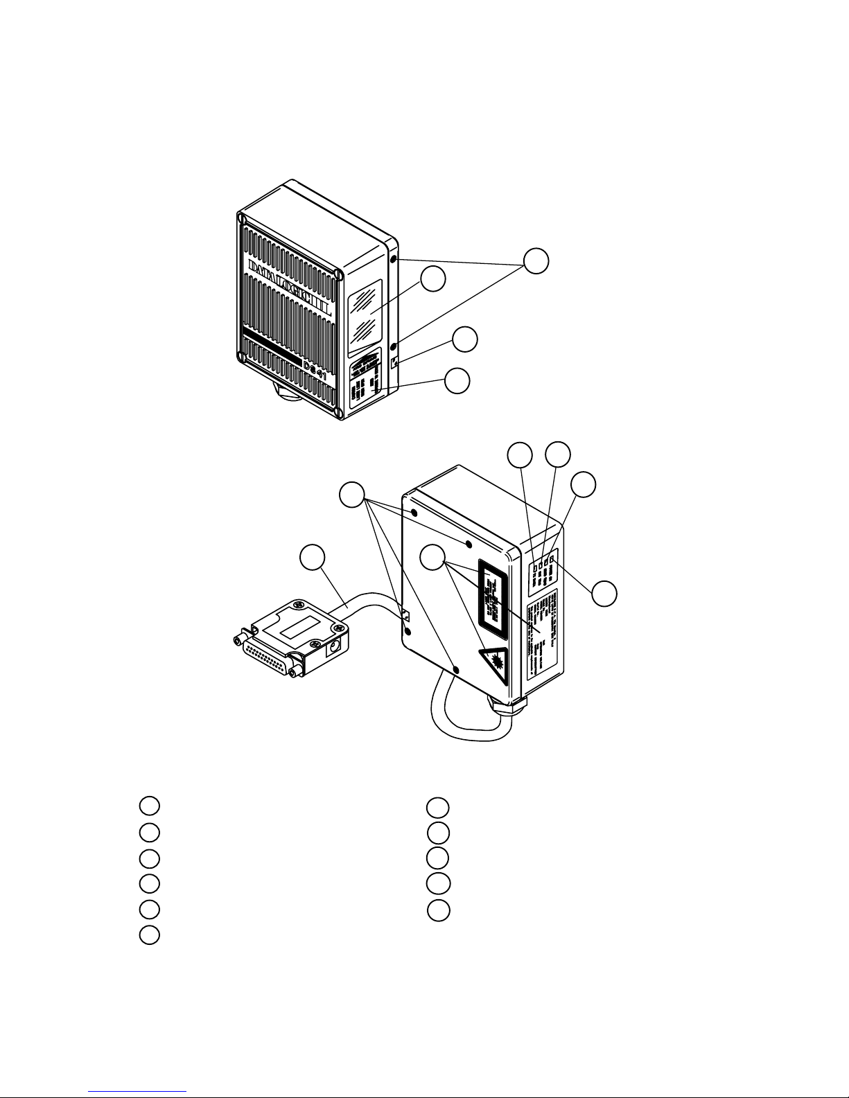
v
DS41
General View
1
11
10
9
8
2
7
6
5
4
3
Figure A
6 Data transmission LED
Cable with 25-pin connector
1
Mounting holes
2
Successful read LED
4
Presence sensor active LED5
Power on LED
3
Laser active LED
9
8
Warning label
Laser beam output window
10
7
Warning and Classification labels
11
Accessory mounting holes
Page 7
vi
DS41
General View
11
10
9
8
2
1
7
6
5
4
3
Figure B
6 Data transmission LED
Cable with junction box
1
Mounting holes
2
Successful read LED
4
Presence sensor active LED5
Power on LED
3
Laser active LED
9
8
Warning label
Laser beam output window
10
7
Warning and Classification labels
11
Accessory mounting holes
Page 8

vii
SAFETY PRECAUTIONS
LASER SAFETY
The following information is provided to comply with the rules imposed by
international authorities and refers to the correct use of the DS41 scanner.
Standard Regulations
This scanner utilizes a low-power laser diode. Although staring direct ly at the
laser beam m omentarily causes no known biological dam age, avoid staring
at the beam as one would with any very strong light source, such as the s un.
Avoid that the laser beam hits the eye of an observer, even through ref lective
surfaces such as mirrors, etc.
This product conform s to the applicable requirements of both IEC 825-1 and
CDRH 21 CFR 1040 at the date of manufac ture. T he s c anner is c lass if ied as
a Class 2 laser product ac cording to IEC 825-1 regulations and as a Class II
laser product according to CDRH regulations.
There is a safety device which allows the laser to be s witched on only if the
motor is rotating above the threshold for its correct scanning speed.
The laser beam c an be switched off through a sof tware command ( see also
“Beam Shutter” in the WINHOST Help On Line).
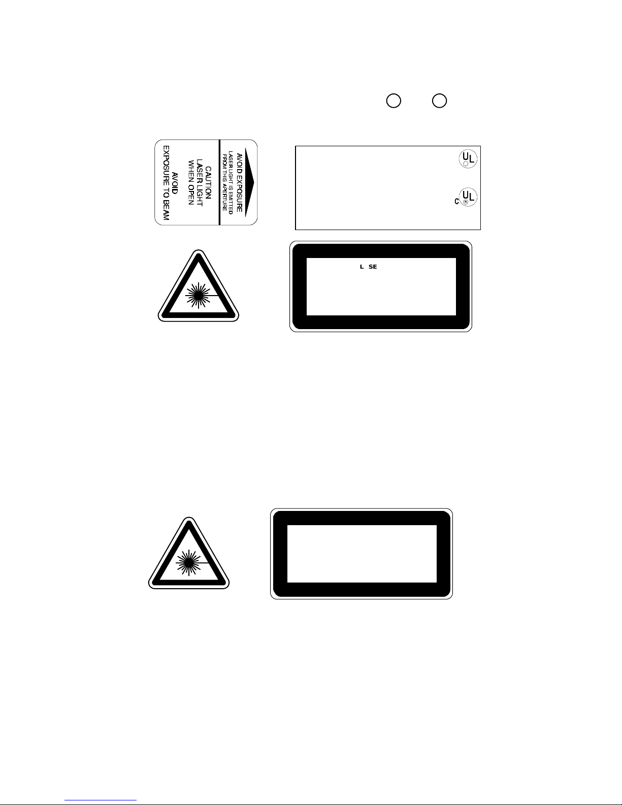
WARNING
Use of controls or adjustments or performance of
procedures other than those specified herein may
result in exposure to hazardous visible laser light.
The laser light is visible to the hum an eye and is em itted f rom the window on
the front of the scanner (Figure A,
10
).
Page 9
viii
W arning labels indicating expos ure to las er light and the devic e c lassif ication
are applied onto the body of the scanner (Figure A,
8
and
7
).
DATALOGIC S. p.A. Via Candini , 2
40012 LIPPO DI CALDERARA (BO) ITALY
Model No. Serial No.
Volt Amp.
Manufactured
This product conforms to the ap plicable requir em ents of
21CFR1040 at the date of manufacture.
LISTED
45AF
I.T.E.
R
R
LASER LIGHT
DO NOT STARE INTO BEAM
CLASS 2 LASER PRODUCT
MAXIMUM OUTPUT RADIATION 1 mW
EMITTED WAVE LENGTH 630~680 nm
TO IEC 825-1 (1993)
Warning and device class label s
Disconnect the power supply when opening the device during maintenance
or installation to avoid exposure to hazardous laser light.
The laser diode used in this device is classified as a class 3B las er product
according to IEC 825-1 regulations and as a Class IIIb laser product
according to CDRH regulations. As it is not poss ible to apply a classification
label on the laser diode used in this device, the following label is reproduced
here:
LASER LIGHT
AVOID EXPOSURE TO BEAM
CLASS 3B LASER PRODUCT
MAX. OUTPUT RADIATION 7 mW
EMITTED WAVE LENGTH 630~680 nm
TO IEC 825-1 (1993)
Laser diode class label
Any violation of the optic parts in particular can cause radiation up to the
maximum level of the laser diode (7 mW at 630 to 680 nm).
Page 10

ix
POWER SUPPLY
ATTENTION:
READ THIS INFORMATION BEFORE INSTALLING THE PRODUCT
- This product is intended to be installed by Qualified Personnel only.
-
Model DS41-X0:
This device is intended to be supplied by a UL Listed Direct Plug-in
Power Unit marked "Class 2", rated 10-30 V, minimum 0.46 A.
This device may also be supplied by a UL Listed Power Unit with a
"Class 2" or LPS power source which supplies power directly to the
scanner via the 25-pin connector.
-
Model DS41-X1:
This device is intended to be supplied via the Junction Box by an NEC
Class 2 power source, rated 10-30 V, minimum 0.46 A.
See par. 2.6.2 or 2.7.1 for correct power supply connections.
Page 11

x
This page is intenti onal l y l ef t blank.
Page 12

DATALOGIC DS41
General features - 1.1
1 GENERAL FEATURES
1.1 INTRODUCTION
The DS41 scanner is a bar code reader complete with decoder , available in
16 standard models. These were designed to satisfy the most demanding
requirements associated with high performance scanning.
Standard Application Program
A Standard Application Program is factory-loaded onto the DS41. This
program controls bar c ode reading, s er ial port inter f ac ing, data f or matting and
many other operating and control parameters.
It is completely user configur able from a host com puter using the WINHOST
interface utility program provided on diskette with the scanner or using the
Host Mode programming procedure, by ESC sequences via the serial
interface.
There are four different programmable operating modes to suit various
barcode reading system requirements. Included in these is a test mode to
verify the reading features and exact positioning of the sc anner without using
external tools.
C Programmability
The DS41 belongs to the generation of Datalogic scanners that operate
under the 'C' programming environment which is a recognized industry
standard.
If your requirements are not met by the Standard Application Program,
Custom Application Programs can be developed by your local Datalogic
distributor.
Page 13

DS41 DATALOGIC
1.2 - General features
1.2 DESCRIPTION
Some of the main features of this scanner are given below:
•
very high scanning speed (800 scans/sec).
•
raster versions available.
•
completely configurable from host computer.
•
2 serial communic ation interfaces; one can be set as RS232, RS485, or
20 mA C.L., and the other is an RS232 auxiliary interface.
•
reads all popular codes.
•
supply voltage from 10 to 30 Vdc.
•
test mode to verify the reading features and exact positioning of the
scanner without the need for external tools.
•
configurable in different oper ating modes to suit the mos t var ious bar c ode
reading system requirements.
•
code verifier
•
possibility to detect the absolute position of the label in the scan line (for
DSP models only, see paragraph 1.3).
•
PCS verification (for DSP models only, see paragraph 1.3).
The DS41 scanner uses a solid state laser diode as a light s ource; the light
emitted has a wavelength between 630 and 680 nm. Refer to the section
"Safety Precautions" at the beginning of this m anual for inform ation on laser
safety.
The use of a semiconductor laser has made it possible to develop an
extremely compact scanner with low power consumption. The reader is
contained in a rugged aluminum housing; the mechanical dimensions are
101 x 83.5 x 42 mm and it weighs about 800 g.
The protection class of the enclosure is IP65, therefore the reader is
particularly suitable for industrial environm ents where high pr otection against
harsh external conditions is required.
Page 14

DATALOGIC DS41
General features - 1.3
Electrical connection is provided through a cable on the side of the reader;
this cable is terminated with a 25-pin connector (25-pin connector models,
see paragraph 1.3, Figure A,
1
) or by a junction box (junction box m odels,
see paragraph 1.3, Figure B,
1
).
The laser beam output window is on the right hand side of the scanner
(Figure A,
10
). A green LED on the same side indicates the laser is active
(Figure A,
9
).
A security system allows the laser to activate only once the motor has
reached the correct rotational speed; consequently the laser beam is
generated after a slight delay from the power on of the scanner.
The four LEDs on the left hand side of the scanner indicate the following:
POWER ON
LED (red) (Figure A, 3) indicates the reader is connected to
the power supply.
GOOD READ
LED (red) (Figure A, 4) is used to signal successful barcode
decoding. It is also used in Tes t m ode to signal the decoding
percentage (for details refer to the s ec tion "T es t Mode" in the
WINHOST Help On Line).
EXT TRIG
LED (yellow) (Figure A, 5) indicates the code presence
sensor is active (for details refer to the section "On Line
Mode" in the WINHOST Help On Line).
TX DATA
LED (green) (Figure A, 6) indicates data transmission on
the main serial output line.
The screw holes on the body of the reader are f or mec hanical fixtur e (Figure
A,
2
); the screw holes shown in Figure A, 11 are to attach accessories such
as the optional 90° mirror.
Page 15
DS41 DATALOGIC
1.4 - General features
1.3 AVAILABLE MODELS
The DS41 scanner is available in versions that differ in regard to the
following parameters:
•
Resolution
•
Termination of the cable
•
Distance between the scan beams (raster models only)
•
DSP or NPP
The following models are therefore available:
DS41 - X X
1 = Standard Resolution = 6
2 = Very High Resolution = 7
3 = Raster Version R2 = 8
4 = Raster Version R1 = 9
Termination of the cable
0 = 25-pin connector
1 = junction box
Optical Resolution
NPP models
Optical Resolution
DSP models
All models perform 800 scans/sec.
1.4 ACCESSORIES
The following accessories are available on request for the DS41:
•
90° deflection mirror GFC-41
Page 16
DATALOGIC DS41
Installation - 2.1
2 INSTALLATION
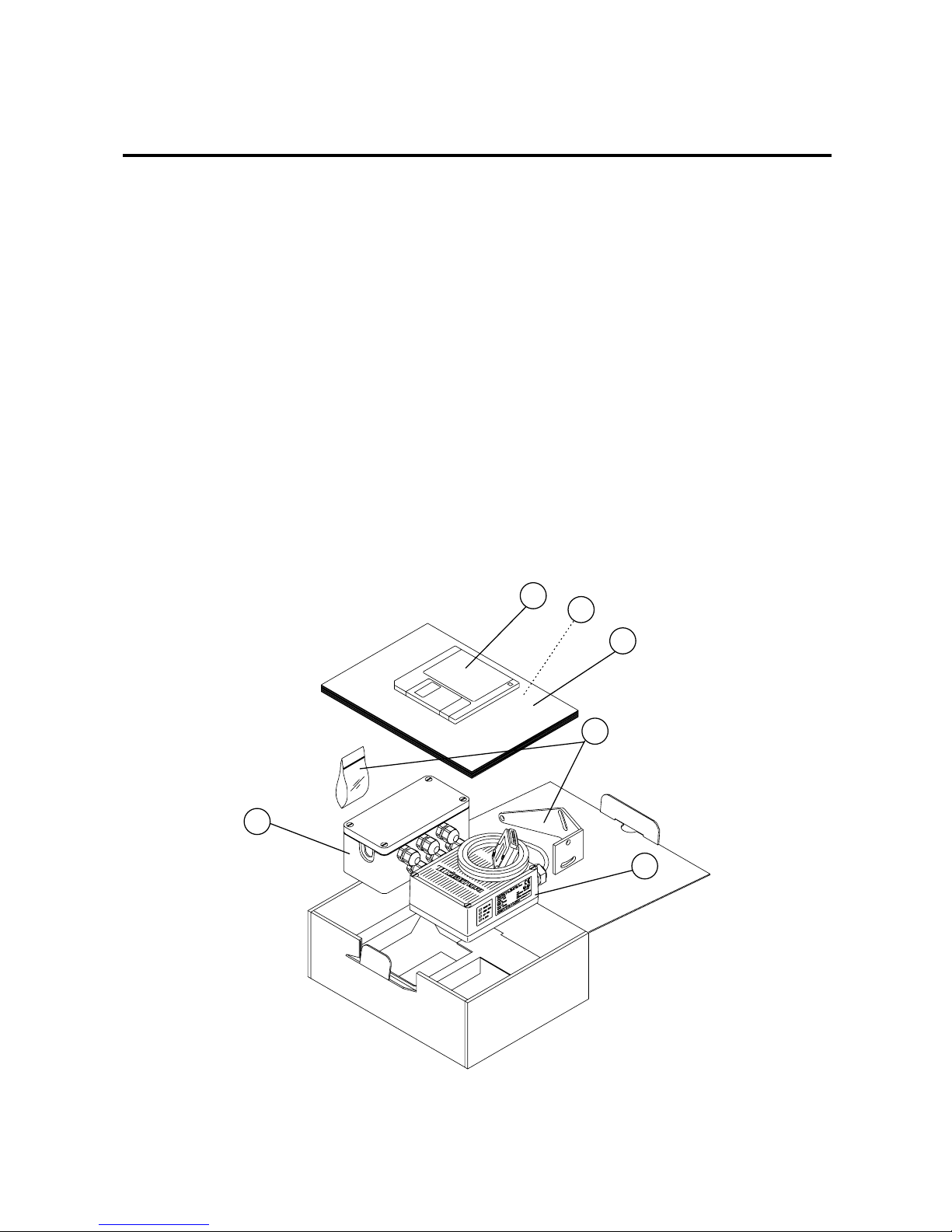
2.1 PACKAGE CONTENTS
Verify that the DS41 reader and all the parts supplied with the equipm ent ar e
present and intact when opening the packaging; the list of parts includes:
1) DS41 reader with cable
2) Installation manual
3) Barcode test chart(s)
4) DS41 communication and utility program disk
5) Mounting kit
•
Mounting screws and washers (4 ea.)
•
Mounting bracket (1)
* Junction box (for junction box models only, see paragraph 1.3)
1
4
3
2
5
*
Figure 2.1 - DS41 package contents
Page 17

DS41 DATALOGIC
2.2 - Installation
2.2 GUIDE TO INSTALLATION
The following can be used as a checklist to verif y all of the steps necessary
for complete installation of the DS41 scanner.
1) Read all information in the section "Safety Precautions" at the
beginning of this manual.
2) Open the scanner to select the main serial interface type as required
(see paragraphs 2.3 and 2.4).
3) Correctly position and mount the scanner for barcode reading
according to the information in paragraphs 2.5, 2.8 and 3.4.
4) Provide correct system cabling according to the signals necessary
(see the applicable sub-paragraphs under 2.6 or 2.7).
5) Configure the software parameters from a host computer using
either the WINHOST interface utility program provided on disk ette, or
using the Host Mode programming procedure, by ESC sequences
via the serial interface.
For more details about these configuration methods refer to the
section "DS41 Configuration" in the WINHOST Help On Line.
NOTE
Fine tuning of the scanner position for
barcode reading can be accom plished using
the Test Mode. For further details refer to the
section "Test Mode" in the WINHOST Help
On Line.
The installation is now complete.
Page 18

DATALOGIC DS41
Installation - 2.3
2.3 OPENING THE DEVICE
Before installing the DS41 it m ay be necessary to open the scanner to select
the interface required.
WARNING
The scanner m ust be dis connected f rom the power
supply during this operation.
Refer to the following instructions and diagram below when opening the
reader:
•
Unscrew the four screws as shown below to open the scanner for
access to the output interface jumper.
•
Carefully remove the cover of the scanner. Avoid any contact with the
mirrored rotor, the lenses, or other optical components.
Figure 2.2 - Opening the DS41
Page 19

DS41 DATALOGIC
2.4 - Installation
2.4 MAIN INTERFACE SELECTION
One of the following interface types can be selected to connect the main
interface of the DS41 to the host computer.
EIA RS232 20 mA CURRENT LOOP
EIA RS485 POLLED EIA RS485 NON POLLED
To select the interface type, position the jumper block as indicated in the
diagram below:
RS232
RS485
POLLED
20 mA C.L.
RS485 NON
POLLED
SW2SW3
SW4
SW2SW3
SW4
SW2SW3
SW4
SW2SW3
SW4
Figure 2.3 - Interface type selection
The RS232 interface type is factory set.
Page 20

DATALOGIC DS41
Installation - 2.5
2.5 MECHANICAL INSTALLATION
DS41 can be installed to operate in different positions. The four s crew holes
(M4 x 5) on the body of the reader are for mechanical fixture (Figure A,
2
).
The diagram below gives the overall dimensions of the scanner and may be
used for its installation.
Refer to paragraph 2.8 for correct positioning.
ST - 37
Mounting
bracket
mm
in
Figure 2.4 - Overall dimensions
Page 21

DS41 DATALOGIC
2.6 - Installation
2.6 JBOX INSTALLATION
JBOX provides a passive connec tion between your scanner and the outside
world in a fast and practical way. It represents an alternative to the 25-pin
connector models. Figure 2.5 shows the basic layout of DS41 using the
junction box.
DS41
Scanner
cable
Junction Box
S
y
stem cables
Figure 2.5 - Scanner using JBOX
For JBOX connections, the scanner has a cable that terminates in a 24-pin
connector that plugs into the junction box . T he system cables pas s through 6
glands in the side of the JBOX and the individual wires connect to spring
clamp terminal blocks inside which provide access to all scanner signals.
2.6.1 Mounting JBOX
The diagram below shows the dim ensions of the junction box and its relative
mounting holes.
mm
in
Figure 2.6 - JBOX dimensions
Page 22

DATALOGIC DS41
Installation - 2.7
JBOX is designed to be mounted to a panel of metal, plastic or other
appropriate material using the m ounting screws pr ovided in the pack age. To
do this:
1) Open the junction box by unscrewing the 4 cover screws.
If necessary, using the two mounting holes inside the junction box as a
pattern, mark the panel with an appropriate object and then dr ill two s m all
pilot holes in the panel.
2) Align the junction box and insert the two self -threading screws with their
washers and screw them into the panel until tight (see Figure 2.7).
Figure 2.7 - Mounting JBOX
Page 23

DS41 DATALOGIC
2.8 - Installation
2.6.2 Electrical Connections for JBOX
The connection and wiring procedure for JBOX is described as follows:
1) Open the junction box by unscrewing the 4 cover screws.
2) Pass all System cables through the glands in the junction box housing.
3) To connect the power and input/output signals:
•
Prepare the individual wires of the system cables by stripping the
insulation back approximately 11 mm.
•
Us ing a device such as a sc rewdriver, push down on the orange lever
directly above the clamp (see Figure 2.8).
•
Insert the wire into the clamp and release the lever.
The wire will now be held in the spring clamp.
Figure 2.8 - System cable connections to the junction box
The wiring used can be solid or stranded but must meet the following
specifications.
Positions 1-4: 24 - 16 AWG 0.2 - 1.5 mm²
Positions 5-39: 26 - 20 AWG 0.14 - 0.5 mm²
The junction box pinouts are indicated in the following table:
Page 24

DATALOGIC DS41
Installation - 2.9
Figure 2.9 - JBOX connector and pinout
To allow connection of an NEC Class 2
Power Unit, use a correct female plug
adapter.
Figure 2.10 - NEC Class 2 Pow er uni t connecti ons
* The signals on pins 24, 25, and 26 are repeated on pins 29, 30, and 31 to fac ilitate network
connections (i. e. Multiplexer connec tions us ing the RS485 P olled Int erface). I n this way the
network bus can enter and exit the junction box from different spring clamps but be
physically connected together.
117
18 39
J1
5
JBOX pinout for DS41
Pin Name
01 VS
02 SGND
03 VS
04 SGND
05 CHASSIS
06 VS
07 VS
08 PS+
09 PS10 SGND
11 SGND
12 VS
13 VS
14 n.c.
15 n.c.
16 SGND
17 SGND
18 NOREAD+
19 NOREAD20 RIGHT+
21 RIGHT22 WRONG+
23 WRONG*24 TX232/TX485+/CLOUT +
*25 RTS232/TX485-/CLOUT*26 SGND
27 n.c.
28 SGND
29 TX232/TX485+/CLOUT+
30 RTS232/TX485-/CLOUT31 SGND
32 RX232/RX485+/CLIN+
33 CTS232/RX485-/CLIN34 SGND
35 TXAUX
36 RTSAUX
37 SGND
38 RXAUX
39 CTSAUX
Junction Box
NEC Class 2
Power supply
Female Plug
System cables
Page 25

DS41 DATALOGIC
2.10 - Installation
4) After wiring the junction box and while the scanner is unplugged from the
power supply, place the Scanner cable so that the rubber seal fits into the
cutout in the housing of the junction box and plug the 24-pin connector
into connector J1 on the PCB inside the junc tion box as shown in figure
2.11.
Scanner cable
J1
Rubber seal
Figure 2.11 - Scanner cable connections to the junction box
5) Close the junction box using the 4 cover screws making sure the rubber
seal is fitted correctly between the parts of the housing.
The junction box is now installed which completes the elec trical connections
for your scanning system.
If it ever becomes necessary to disconnect the scanner from the JBOX,
simply reverse the procedure in step 4.
Page 26

DATALOGIC DS41
Installation - 2.11
2.7 ELECTRICAL CONNECTIONS FOR 25-PIN MODELS
25-pin connector models (see paragraph 1.3) are equipped with a cable
terminated by a 25-pin D-sub connector for connection to the power supply
and input/output signals. The details of the connector pins are indicated in
the following table:
Figure 2.12 - 25-pin D-sub connector
25-pin D-sub connector pinout
Pin Name Function
13 VS Power supply input voltage (+)
25 SGND Power supply input voltage (-)
1 CHASSIS Chassis Ground
9 VS Presence sensor supply voltage (+)
18 PS+ Presence sensor (+)
19 PS- Presence sensor (-)
8 NO READ + No read output (+)
22 NO READ - No read output (-)
11 RIGHT + Right read output (+)
12 RIGHT - Right read output (-)
14 WRONG + Wrong read output (+)
15 WRONG - Wrong read output (-)
2* TX232/TX485+/CLOUT+
3* RX232/RX485+/CLIN+ * Main interface signals
4* RTS232/TX485-/CLOUT- (see par. 2.7.2)
5* CTS232/RX485-/CLIN-
7 SGND Signal Ground
20 RXAUX Auxiliary input
21 TXAUX Auxiliary output
23 CTSAUX Auxiliary handshake
24 RTSAUX Auxiliary handshake
6, 10, 16, 17 NC No Connect
* Pins 2, 3, 4, and 5 of the 25-pin connector have different meanings depending on which
interface type is s elect ed. To selec t the int erface t ype, follow the ins truct ions i n paragraphs
2.3 and 2.4.
Page 27

DS41 DATALOGIC
2.12 - Installation
2.7.1 Power supply
Power can be supplied to the scanner through the pins provided on the 25pin connector used for communication with the host (Figure 2.13):
DS41
13
25
VS
SGND
1
CHASSIS
Earth Grou nd
USER INTERFACE
CHASSIS
GND
V+ (10 - 30 Vdc)
Figure 2.13 - Power supply connections
or through the jack connector on the side of the 25-pin connector for
connections to a UL Listed Direct Plug-in Power Unit (Figure 2.14). If the jack
input is used to supply power to the DS41, pin 13 is automatically
disconnected; the supply voltage for the presence s ensor remains on pin 9.
The plug connector is not supplied with the DS41.
V+ (10 - 30 Vdc)
Jack
Plug
GND
Figure 2.14 - Power supplied using the jack connector
The power must be between 10 and 30 Vdc only. There is a current peak of
about 1A at 10 V during power on caused by the motor starting.
It is recommended to connect pin 1 (CHASSIS) to a common earth ground.
Page 28

DATALOGIC DS41
Installation - 2.13
2.7.2 Main serial interface
The signals relative to the following serial interfac e types are available on the
input/output connector:
EIA RS232
EIA RS485 NON POLLED
EIA RS485 POLLED
(for connection with a Datalogic multiplexer)
20 mA PASSIVE CURRENT LOOP
DS41 automatically recognizes the type of interface s elected at each power
on of the scanner.
If the recognized interface type is not compatible with the current
communication handshaking, then the system forces the XON/XOFF
protocol.
The parameters relative to the interfac e selected (baud rate, data bits, etc.)
can be configured using the WINHOST utility program or Host Mode
programm ing. For more details refer to the section "Main Interface Menu" in
the WINHOST Help On Line.
Details regarding the connections and use of the main interfac e selection ar e
given in the next paragraphs.
Page 29

DS41 DATALOGIC
2.14 - Installation
RS232 interface
The serial interface is used in this case for point to point connections; it
handles comm unication with the host computer and allows both tr ansm iss ion
of code data and the configuration of the scanner. This is the default
interface.
The following pins of the 25-pin connector are used for RS232 interface
connection:
Pin Name Function
2 TX232 Transmitted Data
3 RX232 Received Data
4 RTS232 Request To Send
5 CTS232 Clear To Send
7 SGND Signal Ground
RTS/CTS HARDWARE HAND SHAKING ENABLED
DS41
USER INTERFACE
7
SGND
SGND
RTS232
4
DCD
CTS232
5
DTR
RX232
3
TXD
TX232
2
RXD
Figure 2.15 - RS232 main interface connections
Page 30

DATALOGIC DS41
Installation - 2.15
Figure 2.16 - RS232 control signals
The RTS232 and CTS232 signals control data transm ission and s ynchronize
the connected devices.
If the RTS/CTS handshaking protocol is enabled, the DS41 activates the
RTS232 output to indicate a message is to be trans m itted. The r eceiving unit
activates the CTS232 input to enable the transmission.
RS485 non polled interface
The RS485 NON POLLED interface is a Full Duplex interface.
The NON POLLED conf iguration is used for point to point connections over
longer distances than those acceptable for RS232 communications or in
electrically noisy environments.
The following pins of the 25-pin connector are used for RS485 NON
POLLED communications:
Pin Name Function
2 TX485+ RS485 output (+)
4 TX485- RS485 output (-)
3 RX485+ RS485 input (+)
5 RX485- RS485 input (-)
7 SGND Signal Ground
Page 31

DS41 DATALOGIC
2.16 - Installation
DS41
USER INTERFACE
7
SGND
TX485+
2
TX485-
4
RX485+
3
RX485-
5
RX485
TX485
SGND
Figure 2.17 - RS485 NON POLLED connections
To select this interface type, follow the instructions in paragraphs 2.3 and 2.4.
RS485 polled interface
The RS485 POLLED interface is a Half Duplex (3 wires + shield) interface.
The POLLED configuration can be used for multidrop connections with a
Datalogic multiplexer or it can also be used for a master-slave layout (see
paragraph 2.9.1).
The following pins of the 25-pin connector are used for RS485 POLLED
communications:
Pin Name Function
2 TX485+ RS485 input/output (+)
4 TX485- RS485 input/output (-)
7 SGND Signal Ground
DS41
MULTIPLEXER
TX485+
2
TX485-
4
+ RTX485
- RTX485
7
SGND
RS485REF
Figure 2.18 - RS485 POLLED connections
To select this interface type, follow the instructions in paragraphs 2.3 and 2.4.
Page 32

DATALOGIC DS41
Installation - 2.17
For this interface type, the multidrop address must also be set on the DIP
switch as shown in the figure below. Record this inf orm ation f or f urther setup
of the multidrop line.
SW1
SW2
SW3
SW4
SW1
Figure 2.19 - DIP switch for m u ltidrop address selection
The following table shows the address settings where:
Position Address Position Address
12345 12345
11111 31 01111 15
11110 30 01110 14
11101 29 01101 13
11100 28 01100 12
11011 27 01011 11
11010 26 01010 10
11001 25 01001 9
11000 24 01000 8
10111 23 00111 7
10110 22 00110 6
10101 21 00101 5
10100 20 00100 4
10011 19 00011 3
10010 18 00010 2
10001 17 00001 1
10000 16 00000 0
1 = ON 0 = OFF
Page 33

DS41 DATALOGIC
2.18 - Installation
The figure below shows a multidrop configuration with DS41 scanners
connected to a Multiplexer.
1
1
CHASSIS
DS41
# 1
TX485+
TX485-
SGND
DS41
# 0
max. 1200 m.
three wires
+ shield
7
4
2
7
4
2
120 Ohm
MULTIPLEXER
+RTX485
-RTX485
RS485REF
SHIELD
1
120 Ohm
DS41
(up to 31)
# x
max. 2 m.
7
4
2
Figure 2.20 - DS41 multidrop connection to a Multiplexer
Page 34

DATALOGIC DS41
Installation - 2.19
20 mA current loop interface
The DS41 only supports passive type current loop connections. The following
pins of the 25-pin connector are used:
Pin Name Function
5 CLIN- Current Loop Input (-)
3 CLIN+ Current Loop Input (+)
4 CLOUT- Current Loop Output (-)
2 CLOUT+ Current Loop Output (+)
DS41
USER INTERFACE
5
3
4
C.L. IN-
C.L. IN+
C.L. OUT-
2
C.L. OUT+
MAX. 300 METERS
I = 20 mA
I = 20 mA
Figure 2.21 - 20 mA C.L. connections
To select this interface type, follow the instructions in paragraphs 2.3 and 2.4.
Page 35

DS41 DATALOGIC
2.20 - Installation
2.7.3 Auxiliary RS232 interface
The auxiliary serial interface is used exclusively for RS232 point to point
connections.
The parameter s relative to the auxiliary interface (baud rate, data bits , etc.)
as well as particular operating modes such as local echo can be defined
using the WINHOST utility program or Host Mode programming. For more
details refer to paragr aph 2.9 and to the section "Auxiliar y Interface Menu" in
the WINHOST Help On Line.
The following pins of the 25-pin connector are used to connect the RS232
auxiliary interface:
Pin Name Function
20 RXAUX Auxiliary input
21 TXAUX Auxiliary output
23 CTSAUX Auxiliary handshake
24 RTSAUX Auxiliary handshake
7 SGND Signal Ground
7
SGND
SGND
DS41
USER INTERFACE
TXD
RXAUX
20
RXD
TXAUX
21
RTS/CTS HARDWARE HANDSHAKING ENABLED
DCD
RTSAUX
24
DTR
CTSAUX
23
Figure 2.22 - RS232 auxiliary interface connections
The RTSAUX and CTSAUX signals control data transmission and
synchronize the connected devices. If the RTS/CTS handshaking pr otocol is
enabled, the DS41 activates the RTSAUX output to indicate a m essage is to
be transmitted. T he receiving unit activates the CTSAUX input to enable the
transmiss ion.
Page 36

DATALOGIC DS41
Installation - 2.21
2.7.4 Inputs
The inputs available on the DS41 scanner are the pins relative to the code
presence sensor, as indicated below:
Pin Name Function
18 PS+ Presence sensor (input+)
19 PS- Presence sensor (input-)
The inputs indicated are always used to connect the code pres ence sensor
which tells the scanner to sc an for a code. The yellow led (Figur e A,
5
) is
on during the active phase of the PS signal indicating that decoding can tak e
place.
This input is optocoupled and can be driven by both an NPN or PNP type
command. The connections are indicated in the following diagrams:
PRESENCE SENSORDS41
30 Vdc max.
Vext
PS+
PS-
18
19
+ 5V
Signal
V
Figure 2.23 - Input NPN command using external power
PRESENCE SENSORDS41
Signal
PS+
PS-
18
19
+ 5V
VS
9
25
GND
Ground
V
Figure 2.24 - Input NPN command using DS41 power
Page 37

DS41 DATALOGIC
2.22 - Installation
PS+
PS-
18
19
+ 5V
DS41
PRESENCE SENSOR
V
Signal
Ground
30 Vdc max.
Vext
Figure 2.25 - Input PNP command using external power
PRESENCE SENSOR
DS41
PS+
PS-
18
19
VS
9
25
GND
V
Signal
+ 5V
Figure 2.26 - Input PNP command using DS41 power
The electrical features are given below:
Maximum voltage 30 Vdc
Maximum current 25 mA
An anti-disturbance filter is im plem ented on the pr esence sens or input with a
nominal delay of about 5 milliseconds.
Page 38

DATALOGIC DS41
Installation - 2.23
2.7.5 Outputs
In addition to the pins relative to the comm unication interfaces as described
in the previous paragraphs, the following pins are present on the 25-pin
connector of the scanner:
Pin Name Function
8 NO READ+ No read output (+)
22 NO READ- No read output (-)
11 RIGHT+ Right read output (+)
12 RIGHT- Right read output (-)
14 WRONG+ Wrong read output (+)
15 WRONG- Wrong read output (-)
The NO READ output activates when the code signalled by the presence
sensor is not decoded.
DS41
USER INTERFACE
22
8
NO READ-
NO READ+
40 Vdc max
Vext
Figure 2.27 - NO READ output connection
The RIGHT output activates when the code is decoded correctly.
DS41
USER INTERFACE
Vext
40 Vdc max
RIGHT+
RIGHT-
11
12
Figure 2.28 - RIGHT code output connection
Page 39

DS41 DATALOGIC
2.24 - Installation
The WRONG output is used either for "Verifier" mode or for PCS control
(PCS control is available for DSP models only, see paragraph 1.3). For
Verifier this output activates when the decoded code does not c orrespond to
the one set in the configuration. For PCS this output activates when the PCS
level is below the threshold value.
DS41
USER INTERFACE
Vext
40 Vdc max
WRONG+
WRONG-
14
15
Figure 2.29 - WRONG code output connection
These outputs are all level or pulse programmable: a 50 ms pulse is
generated in the second case. Further program ming information is supplied
in the section "Output Lines" in the WINHOST Help On Line.
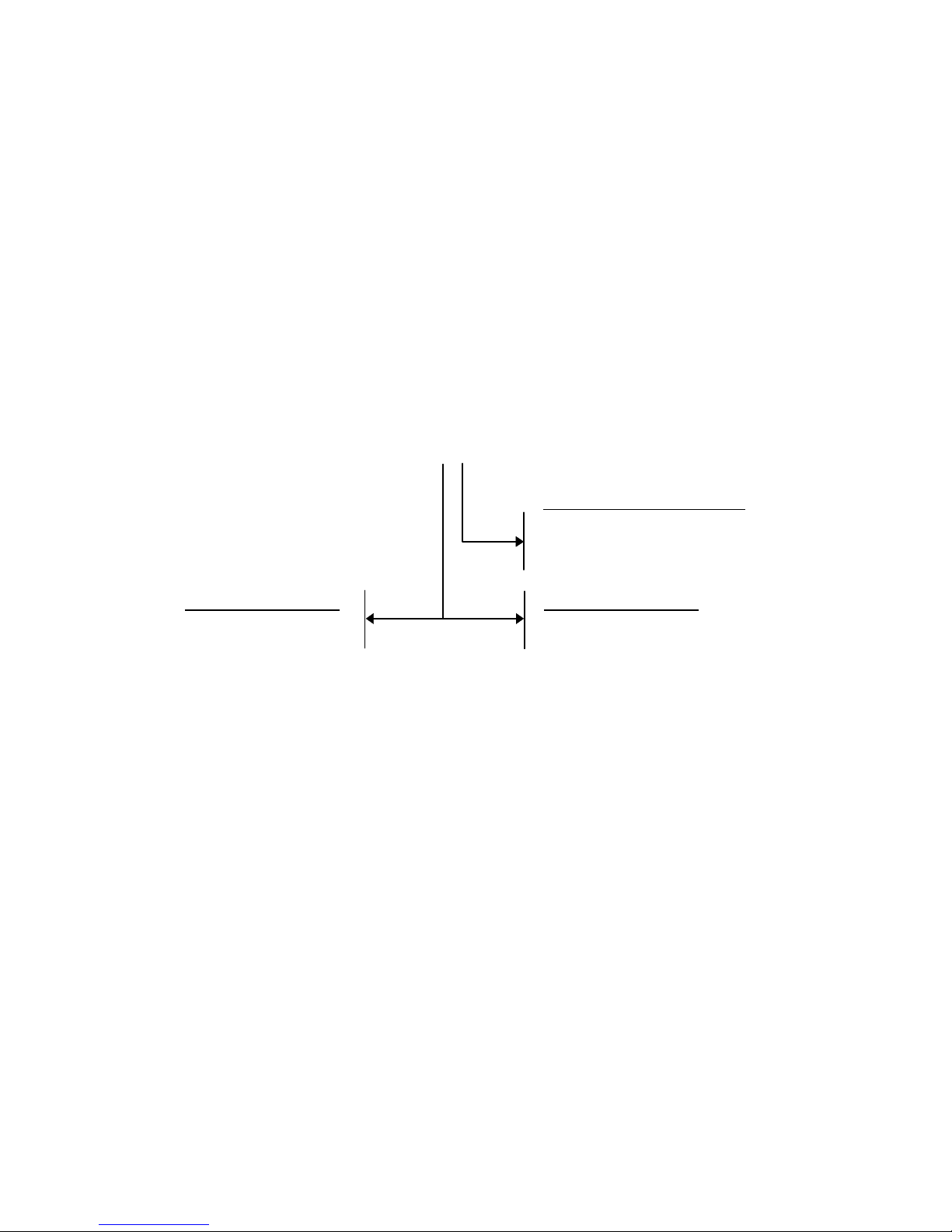
2.8 POSITIONING
The DS41 scanner is able to decode moving barcode labels at a variety of
angles, however significant angular distortion may degrade reading
performance.
When mounting the DS41 take into consideration these three ideal label
position angles:
Pitch 0° , Skew 10° to 30° and Tilt 0°
.
Follow the suggestions below for the best orientation:
The
Pitch
angle is represented by the value P in figure 2.30. Position the
reader in order to
minimize
the
Pitch
angle.
Page 40

DATALOGIC DS41
Installation - 2.25
P
Figure 2.30 - Pitch angle
The
Skew
angle is represented by the value S in Figure 2.31. Position the
reader to
assure at least 10°
for the
Skew
angle. This avoids the direct
reflection of the laser light emitted by the DS41.
For raster models, this angle refers to the most inclined or external raster
line, so that all other raster lines assure
more
than 10° Skew.
S
Figure 2.31 - Skew Angle
The
Tilt
angle is represented by the value T in figure 2.32. Position the
reader in order to
minimize
the
Tilt
angle.
T
Figure 2.32 - Tilt angle
Page 41

DS41 DATALOGIC
2.26 - Installation
2.9 TYPICAL LAYOUTS
The DS41 barcode reader was specifically designed for industrial
applications. A typical use is real time identification of moving objects on
conveyor belts.
A photoelectric sensor used as a code presence sensor signals when an
object enters the scanner reading zone (see Figure 2.33).
1
2
Host
DS41
2
Main serial interface
Presence sensor
1
Figure 2.33 - DS41 typical layout
DS41 can be mounted vertically or horizontally to read labels in the two
standard 'picket fence' or 'step ladder' pos itions. A system c an be configured
to read labels in any orientation using several scanners positioned at different
angles.
For each application it is advised that the length of the scan line, the scan
speed, the height of the bars and the code motion speed with respect to the
scanner, allow at least five scans on the code.
The possibility of using raster models allows a greater surface area of the
code to be scanned, increasing the probability of correct reads even if the
code printing quality is poor or the code is positioned incorrectly.
Page 42

DATALOGIC DS41
Installation - 2.27
2.9.1 Master-slave
The master-slave layout is used to collect data from several scanners to
build a multi-sided reading system; there can be one master and up to 5
slaves connected with the RS485 polled mode on the main serial interface.
The master scanner is also connected to a host computer with the RS232
auxiliary interface.
The P.S. signal is unique to the system; there is a single reading phas e and
a single message from the master scanner to the host computer.
In every scanner the jumper block for the selection of the main serial
interface type must be set for RS485 polled (see paragraph 2.4).
In every slave scanner the multidrop address s elec tion must be set within the
range from 0 to 4 max (see paragraph 2.7.2 under "RS485 polled interface").
The DIP switch selections in the master scanner are ignored.
Host
DS41 Master
1
3
2
Main serial interface
1
Auxiliary serial interface
3 Presence sensor
2
DS41 Slave
2
DS41 Slave
2
Figure 2.34 - Master-slave layout
NOTE
The auxiliary serial port of the slave scanners is
only used for configuration.
The termination resistors of the RS485 bus must
not be installed.
Page 43

DS41 DATALOGIC
2.28 - Installation
2.9.2 Local echo
In local echo mode data is tr ans mitted on the auxiliary interface as well as on
the main interface.
Host Mode programming can be accomplished either through the main
interface or the auxiliary interface in local echo mode.
DS41
2
3
Terminal
1
Host
2
3
Main serial interface
Auxiliary serial interface
Presence sensor
1
Figure 2.35 - Local echo layout
2.9.3 Pass through
Pass through mode allows two or m ore devices to be connec ted to a single
external serial interface.
Each DS41 transmits the messages received by the auxiliary interface onto
the main interface.
All messages will be passed through this chain to the host. The main and
auxiliary ports are connected as shown in the figure below:
2
3
3
1
1
Main serial interface
2 Auxiliary serial interface
3 Presence sensor
Host
1
DS41 DS41
Figure 2.36 - Pass through layout
Page 44

DATALOGIC DS41
Reading features - 3.1
3 READING FEATURES
The number of reads performed by the DS41 and therefore the decoding
capacity, is influenced by the following parameters:
•
number of scans per second
•
code motion speed
•
label dimensions
•
scan direction in respect to code motion
At least 5 scans during the code passage should be allowed to ensure a
successful read.
3.1 STEP LADDER MODE
Code motion
moving at LS speed
LH
Laser Beam
DS41
Figure 3.1 - "Step Ladder" scanning mode
If scanning is perpendic ular to the code motion direction (Figure 3.1 - "step
ladder" mode), the number of effective scans performed by the reader is
given by the following formula:
SN = [(LH/LS) * SS] - 2
These symbols signify:
SN = number of effective scans
LH = label height (in mm)
LS = label movement speed (in mm/s)
SS = number of scans per second
Page 45

DS41 DATALOGIC
3.2 - Reading features
For example, the DS41 (800 scans/s ec.), for a 25 mm high c ode moving at
1250 mm/s performs:
[(25/1250) * 800] - 2 = 14 effective scans.
3.2 PICKET FENCE MODE
FW
LW
Code motion
moving at LS speed
Laser Beam
DS41
Figure 3.2 - "Picket Fence" scanning mode
If scanning is parallel to the code motion, (Figur e 3.2 - "picket f ence" mode) ,
the number of effective scans is given by:
SN = [((FW-LW)/LS) * SS] - 2
These symbols signify:
SN = number of effective scans
FW = reading field width (in mm)
LW = label width (in mm)
LS = label movement speed (in mm/s)
SS = scans per second
For example, for a 50 mm wide code moving in a point where the reading
field is 250 mm wide at a 1500 mm /s speed, the DS41 (800 s cans per sec .),
performs :
[((250-50)/1500) * 800] - 2 = 104 scans
Page 46

DATALOGIC DS41
Reading features - 3.3
3.3 PERFORMANCE
The DS41 scanner is available in four standard versions according to the
optical resolution characteristics (see paragraph 1.3).
The Standard resolution version is a general purpose model whose optical
resolution allows code reading from 0.20 mm to 1.00 mm narrow bars in the
zone between 50 and 400 mm from the emission window. This version can
distinguish between high density codes (between 0.20 mm and 0.30 mm)
and low density codes (above 0.33 mm) by programming the software
resolution parameter (see the section "Scanner Res olution" in the WINHOST
Help On Line).
The Very High resolution version has an optical resolution that allows reading
very high density codes (typical values from 0.10 mm to 0.20 mm narrow
bars) in the zone from 55 to 125 mm from the emission window. The
software resolution param eter for this vers ion should be set to high (see the
section "Scanner Resolution" in the WINHOST Help On Line).
The Raster version R1 is a raster model used to read codes from 0.20 mm to
1.00 mm narrow bars with a raster aperture of about 12 mm at a 200 mm
distance.
The Raster version R2 is a raster model used to read codes from 0.20 mm to
1.00 mm narrow bars with a raster aperture of about 40 mm at a 200 mm
distance.
Refer to the diagrams given in paragraph 3.4 for further details on the
reading features. Thes e diagrams refer to the two standard optical versions
and are taken on various resolution sample codes at a 25 °C ambient
temperature, depending on the conditions in the notes under each diagram.
If standard devices do not s atisfy specif ic requirem ents , contac t your nearest
Datalogic distributor, supplying code samples, to obtain com plete infor m ation
on the reading possibilities.
Page 47

DS41 DATALOGIC
3.4 - Reading features
3.4 READING DIAGRAMS
DS41-1x and DS41-6x
(Standard Resolution, 800 scans/s)
NOTE: (0,0) IS THE CENTER OF THE LASER BEAM OUTPUT WINDOW
0.30 mm
0.20 mm
CONDITIONS:
Code = Interleaved 2/5 or Code 39
PCS = 0.90
"Pitch" angle = 0
°
"Skew" angle = 10
°
"Tilt" angle = 0
°
SW Resolution = High
Page 48

DATALOGIC DS41
Reading features - 3.5
DS41-1x and DS41-6x
(Standard Resolution, 800 scans/s)
NOTE: (0,0) IS THE CENTER OF THE LASER BEAM OUTPUT WINDOW
0.50 mm
0.60 mm
0.80 mm
1.00 mm
CONDITIONS:
Code = Interleaved 2/5 or Code 39
PCS = 0.90
"Pitch" angle = 0
°
"Skew" angle = 10
°
"Tilt" angle = 0
°
SW Resolution = Low
Page 49

DS41 DATALOGIC
3.6 - Reading features
DS41-2x and DS41-7x
(Very High resolution, 800 scans/s)
NOTE: (0,0) IS THE CENTER OF THE LASER BEAM OUTPUT WINDOW
0.20 mm
0.15 mm
0.10 mm
CONDITIONS:
Code = Interleaved 2/5 or Code 39
PCS = 0.90
"Pitch" angle = 0
°
"Skew" angle = 10
°
"Tilt" angle = 0
°
SW Resolution = High
Page 50

DATALOGIC DS41
Maintenance - 4.1
4 MAINTENANCE
4.1 CLEANING
Clean the laser beam output window periodically for continued correct
operation of the reader.
Dust, dirt, etc. on the window may alter the reading performance.
Repeat the operation frequently in particularly dirty environments.
Use soft material and alcohol to clean the window and avoid any abrasive
substances.
WARNING
Clean the window of the DS41 when the scanner is
turned off or, at least when the laser beam is deactivated.
Page 51

DS41 DATALOGIC
4.2 - Maintenance
This page is intenti onal l y l ef t blank.
Page 52

DATALOGIC DS41
Technical features - 5. 1
5 TECHNICAL FEATURES
DSP MODELS
(Note 1)
NPP MODELS
(Note 1)
ELECTRICAL FEATURES
INPUT POWER
Supply voltage 10 to 30 Vdc
Power consumption max. 5 W 4 W
SERIAL INTERFACES
MAIN RS232, RS485 Non Polled, RS485 Polled,
20 mA Pass ive C. L.
AUXILIARY RS232
BAUD RATES
All Interfaces 150 to 19200
CONTROL INPUTS
PRESENCE SENSOR (optocoupled NPN or PNP)
Voltage max. 30 Vdc
Input current m ax. 25 mA
CONTROL OUTPUTS
NO READ, RIGHT READ, WRONG READ (optocoupled)
V
CE
max. 40 Vdc
Collector current max. 40 mA continuous; 130 mA pulsed
VCE saturation 1V at 10 mA max.
Power dissipation m ax.
90 mW at 40 °C (Ambient temp.)
OPTICAL FEATURES
Light source Semiconductor laser diode
Wave length (Note 2) 630 ~ 680 nm
Safety class Class 2
READING FEATURES
(Note 3)
Scan rate 800 scans/second
Reading distance 50 to 400 mm
Maximum resolution 0.1 mm
Aperture angle 60 degrees
USER INTERFACE
LED indicators power, laser beam active, barcode decoded,
presence sensor act i ve, data transmis sion
Page 53

DS41 DATALOGIC
5.2 - Technical feat ures
DSP MODELS
(Note 1)
NPP MODELS
(Note 1)
SOFTWARE FEATURES
READABLE CODE SYMBOLOGIE S
Up to 22 readable symbologies including:
Code 93 (Standard and Full ASCII )
• •
EAN/UPC (including Add-on 2 and Add-on 5)
• •
Code 39 (Standard and Full ASCII )
• •
2/5 Interleaved
• •
Codabar
• •
Code 128
• •
EAN 128
• •
Plessey
•
CODE SELECTION
up to six codes during one reading phase
CODE POSITON
can be verified and
displayed
cannot be verified
and displayed
DECODING SAFETY
can enable multiple good reads of same
code
HEADERS AND TERMI NATORS
up to four headers and four terminators
OPERATING MODES
ON LINE, AUTOMATIC, SERIAL ON LINE, TEST
CONFIGURATION MODES
• through menus using WINHOST ut ility
• receiving commands from one of the
serial ports (HOST MODE)
PARAMETER STORAGE
Non-volatile internal EEPROM
ENVIRONMENTAL FEATURES
Operating temperature (Not e 4)
0 to 40 °C
Storage temperature
-20 to 70 °C
Humidity m ax. 90% non condensing
Vibration resistance IEC 68-2-6 test FC 1.5 mm;
10 to 55 Hz; 2 hours on each axis
Shock resistance IEC 68-2-27 test EA 30G;
11 ms; 3 shocks on each axis
Protection class IP65
PHYSICAL FEATURES
Mechanical dimens i ons 101 x 83.5 x 42 mm
Weight 800 g.
Note 1: Refer to paragraph 1.3 for model descript i ons.
Note 2: The features given are typical at a 25 °C ambient temperature (if not otherwise
indicated).
Note 3: Further details given in paragraphs 3.3 and 3.4.
Note 4: If the reader is used in high tem perature environm ent s (over 35 °C), us e of the B eam
shutter is advis ed (for details ref er to the sect ion "Beam shut ter" in the Help On Line
of the WINHOST utility program provided with the DS41 dis k.
 Loading...