


DS2400
Installation Manual

DS2400
Installation Manual

DS2400
INSTALLATION MANUAL

DATALOGIC S.p.A.
Via Candini 2
40012 - Lippo di Calderara di Reno
Bologna - Italy
DS2400
Ed.: 01/2002
Datalogic reserves the right to make modifications and improvements without prior notification.
Datalogic shall not be liable for technical or editorial errors or omissions contained herein, nor for incidental or
consequential damages resulting from the use of this material.
Product names mentioned herein are for identification purposes only and may be trademarks and or
registered trademarks of their respective companies.
© Datalogic S.p.A. 1999 - 2002
821000423 (Rev. C)

CONTENTS
GUIDE TO INSTALLATION ......................................................................... v
GENERAL VIEW ..........................................................................................vi
SAFETY PRECAUTIONS............................................................................vii
Laser Safety.............................................................................................vii
Standard Regulations...............................................................................vii
Power Supply........................................................................................... ix
1 GENERAL FEATURES ................................................................................ 1
1.1 Introduction ................................................................................................... 1
1.2 Description.................................................................................................... 2
1.3 Available Models........................................................................................... 3
1.4 Accessories................................................................................................... 4
1.5 GFC-2100 Accessory Installation.................................................................. 4
2 INSTALLATION............................................................................................ 5
2.1 Package Contents......................................................................................... 5
2.2 Mechanical Installation.................................................................................. 6
2.3 Junction Box Installation ............................................................................... 7
2.3.1 Junction Box Mounting.................................................................................. 7
2.3.2 Junction Box Electrical Connections............................................................. 9
2.4 Electrical Connections ................................................................................ 12
2.4.1 Power Supply.............................................................................................. 13
2.4.2 Main Serial Interface................................................................................... 13
RS232 Interface ......................................................................................14
RS485 Full-Duplex Interface ...................................................................15
RS485 Half-Duplex Interface...................................................................16
20 mA Current Loop Interface (INT-22 Accessory Only)......................... 17
2.4.3 Auxiliary RS232 Interface............................................................................ 18
Code Verifier ........................................................................................... 19
2.4.4 Inputs .......................................................................................................... 19
2.4.5 Outputs ....................................................................................................... 21
2.5 Positioning .................................................................................................. 22
2.6 Typical Layouts........................................................................................... 23
2.6.1 Point-to-Point .............................................................................................. 24
2.6.2 Pass Through.............................................................................................. 25
2.6.3 RS232 Master/Slave................................................................................... 26
2.6.4 RS485 Master/Slave................................................................................... 27
2.6.5 Multiplexer................................................................................................... 28
iii

3 READING FEATURES ............................................................................... 29
3.1 Step-Ladder Mode ...................................................................................... 29
3.2 Picket-Fence Mode..................................................................................... 30
3.3 Performance ............................................................................................... 31
3.3.1 Raster ......................................................................................................... 31
3.4 Reading Diagrams ...................................................................................... 32
4 MAINTENANCE.......................................................................................... 34
4.1 Cleaning...................................................................................................... 34
5 TECHNICAL FEATURES ........................................................................... 35
iv

GUIDE TO INSTALLATION
The following can be used as a checklist to verify all of the steps necessary for
complete installation of the DS2400 scanner.
1) Read all information in the section "Safety Precautions” at the beginning of this
manual.
2) Correctly position and mount the scanner for barcode reading according to the
information in par. 2.2, 2.5 and 3.4.
3) Provide correct system cabling according to the signals necessary for your
application (see all sub-paragraphs under 2.3 and 2.4). See also sub-paragraphs
under 2.6 for reference.
4) Install the Configuration Disk.
Upon successful completion of the installation, the readme.hlp file is opened,
giving details about how to get started configuring your scanner.
See also the Guide To Rapid Configuration link.
Specific parameter details are available in the Help On Line.
Fine tuning of the scanner position for barcode reading can be
accomplished using the Test Mode as described in WinHost.
NOTE
The installation is now complete.
v
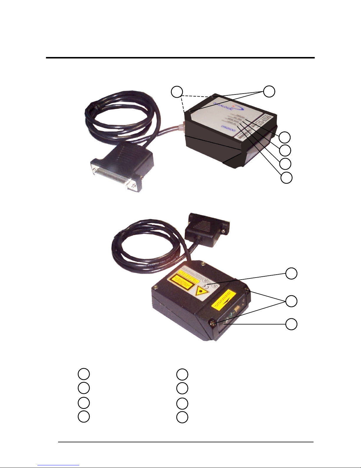
GENERAL VIEW
DS2400
8
8
1
2
3
4
Power ON \ Data Tx LED
1
2
External Trigger LED
Good Read LED
3
Laser ON LED
4
Figure A
5
6
7
8
5
7
6
Warning and Device Class Labels
Laser Beam Output Window
Accessory Mounting Holes
Mounting Holes
vi
SAFETY PRECAUTIONS
LASER SAFETY
The following information is provided to comply with the rules imposed by
international authorities and refers to the correct use of the DS2400 scanner.
Standard Regulations
This scanner utilizes a low-power laser diode. Although staring directly at the laser
beam momentarily causes no known biological damage, avoid staring at the beam as
one would with any very strong light source, such as the sun. Avoid that the laser
beam hits the eye of an observer, even through reflective surfaces such as mirrors,
etc.
This product conforms to the applicable requirements of both IEC 825-1 and CDRH
21 CFR 1040 at the date of manufacture. The scanner is classified as a Class 2 laser
product according to IEC 825-1 regulations and as a Class II laser product according
to CDRH regulations.
There is a safety device which allows the laser to be switched on only if the motor is
rotating above the threshold for its correct scanning speed.
The laser beam can be switched off through a software command (see also «Beam
Shutter» in the WinHost Help On Line).
Use of controls or adjustments or performance of procedures other
than those specified herein may result in exposure to hazardous
WARNING
The laser light is visible to the human eye and is emitted from the window on the front
of the scanner (Figure A, 6).
visible laser light.
vii
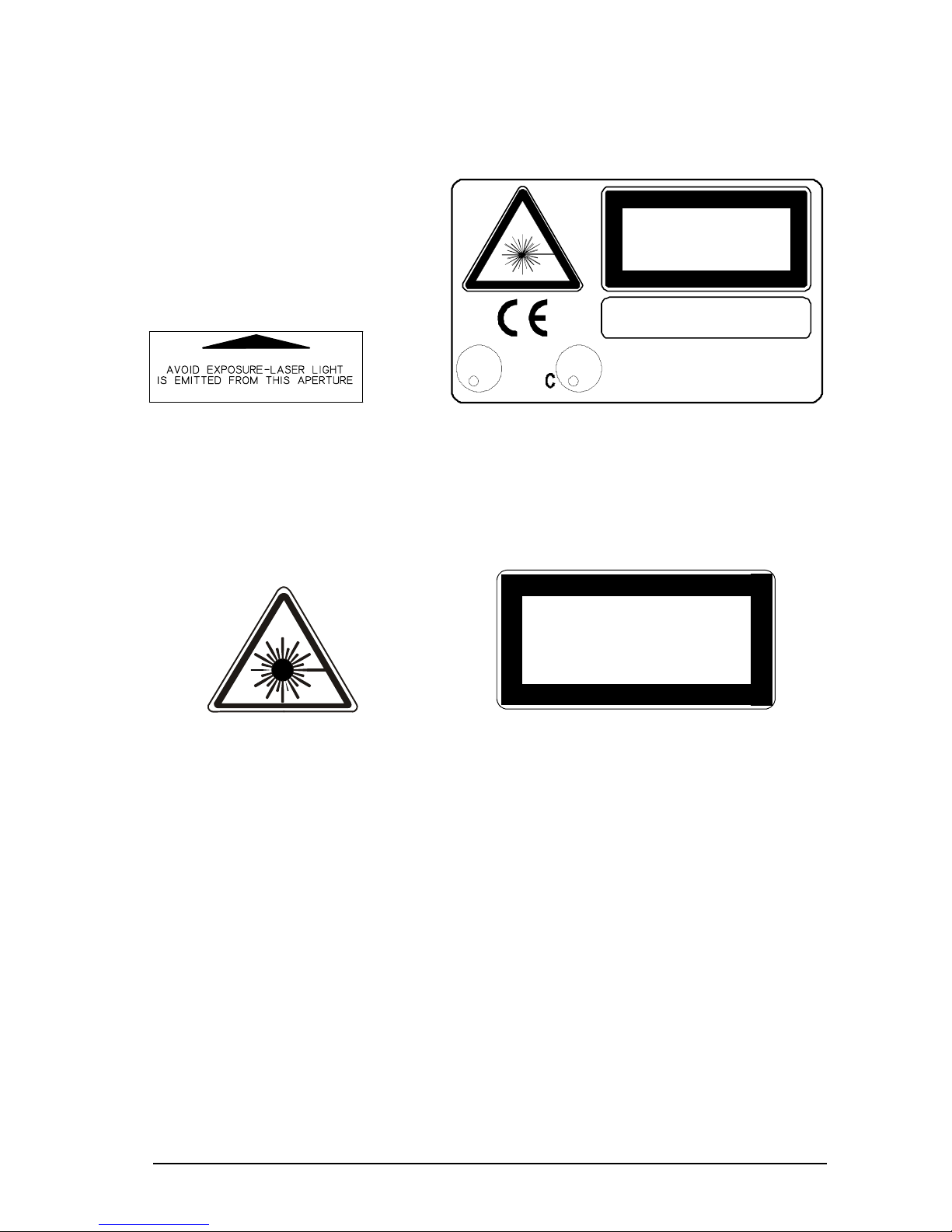
Warning labels indicating exposure to laser light and the device classification are
applied onto the body of the scanner (Figure A, 5).
LASER LIGHT
DO NOT S TARE INT O BEAM
CLASS 2 LASER PRODUCT
MAX. OUTPUT RADIATION 1 mW
EMITTED WAVE LENGTH 630~680 nm
TO IEC 825-1 (1993)
CAUTION - LASER LIGHT WHEN OPEN
AVOID E XPOSURE T O BEAM
U
R
L
LISTED
ACCES SORY
45AF
I.T.E.
This product conforms to the applicable
U
requirements of 21CFR1040 at the date
L
R
of manufacture.
Warning and device class labels
Disconnect the power supply when opening the device during maintenance or
installation to avoid exposure to hazardous laser light.
LASER LIGHT
AVOID EXPOSURE TO BEAM
CLASS 3B LASER PRODUCT
MAX. OUTPUT RADIATION 7 mW
EMITTED WAVE LENGTH 630~680 nm
TO IEC 825- 1 (1993)
Laser diode class label
The laser diode used in this device is classified as a class 3B laser product according
to IEC 825-1 regulations and as a Class IIIb laser product according to CDRH
regulations. As it is not possible to apply a classification label on the laser diode used
in this device, the following label is reproduced on the right.
Any violation of the optic parts in particular can cause radiation up to the maximum
level of the laser diode (7 mW at 630 to 680 nm).
viii

POWER SUPPLY
- This product is intended to be installed by Qualified Personnel only.
- Models DS2400-XXX0:
This accessory device is intended to be supplied by a UL Listed Power Unit with
«Class 2» or LPS power source which supplies power directly to the scanner via the
25-pin connector.
- Model DS2400-XXX1:
This accessory device is intended to be supplied via the Junction Box by an NEC
Class 2 Power Source rated 10-30 V, minimum 0.55 A.
ix

x

GENERAL FEATURES
1
1 GENERAL FEATURES
1.1 INTRODUCTION
The DS2400 laser scanner satisfies the most advanced needs of a wide range of
users. It has been developed focusing on the realistic requirements of its target
market. The outstanding result is an extremely compact, cost-effective and easy to
use industrial scanner.
C-Programmability The DS2400 belongs to the generation of Datalogic scanners
that operate under the 'C' programming environment, which
is a recognized industry standard.
Standard Application
Program
Custom Application
Programs
A standard application program is factory-loaded onto the
DS2400. This program controls barcode reading, serial port
interfacing, data formatting and many other operating and
control parameters.
It is completely configurable from a host computer through
the WinHost utility program provided on diskette with the
scanner, or through ESC sequences via the serial interface.
If the Standard Application Program does not meet your
requirements, please contact your local Datalogic distributor.
1

1
DS2400
1.2 DESCRIPTION
Some of the main features of DS2400 are listed below:
• small dimensions and light weight.
• software programmable scanning speed (400 to 1000 scans/sec) on all models.
• linear and raster versions.
• connector and junction box versions.
• completely configurable via serial interface (WinHost).
• 2 serial communication interfaces.
• supply voltage from 10 to 30 Vdc.
• reads all popular codes.
• test mode to verify the reading features and exact positioning of the scanner
without the need for external tools.
• programmable in 4 different operating modes to suit the most various barcode
reading system requirements.
• code verifier.
The DS2400 uses a solid state laser diode as a light source; the light emitted has a
wavelength between 630 and 680 nm. Refer to the section “Safety precautions” at
the beginning of this manual for information on laser safety.
The protection class of the enclosure is IP65, the reader is therefore suitable for
industrial environments where high protection against harsh external conditions is
required.
The four LEDs on the side of the scanner indicate the following:
PWR/TXD
LED (red) (Figure A, 1) indicates the reader is connected to the
power supply or, when blinking (green), data transmission.
GOOD READ
LED (red) (Figure A, 3) is used to signal the possibility of a
successful barcode reading.
EXT TRIG
LED (yellow) (Figure A, 2) indicates external trigger activity. Refer
to par. 2.4.4.
LASER ON LED (green) (Figure A, 4) indicates laser ON state.
The screw holes on the body of the reader are for mechanical fixture (Figure A, 8).
2

GENERAL FEATURES
1
1.3 AVAILABLE MODELS
The DS2400 scanner is available in versions that differ in regard to the following
parameters:
• Reading range
• Serial interfaces
• Linear or raster reading
• Connections
The following models are therefore available:
DS2400 - X X X X
Reading Range
1 = Medium range
2 = Long range
Serial Communication Interface
0 = RS232 main + RS232 aux
1 = RS485 main + RS232 aux
Connections
0 = Connector
1 = Junction Box
Linear/Raster
0 = Linear
1 = Raster
The following tables display each version’s reading performance.
Version Max Code Resolution Speed
mm (mils) scans/s
1XXX 0.25 (10) 400 to 1000
2XXX 0.35 (14) 400 to 1000
Version Reading Distance
1XXX 100 mm (4 in) - 440 mm (17 in) on 0.50 mm (20 mils) codes
2XXX 200 mm (8 in) - 600 mm (23.5 in) on 0.50 mm (20 mils) codes
See reading diagrams in par. 3.4 for further details.
3
 Loading...