

Page 1
DS2100N
Reference Manual
Page 2

Datalogic Automation Srl
Via S. Vitalino, 13
40012 - Lippo di Calderara di Reno
Bologna - Italy
DS2100N Reference Manual
Ed.: 09/2008
ALL RIGHTS RESERVED
Datalogic reserves the right to make modifications and improvements without prior notification.
Datalogic shall not be liable for technical or editorial errors or omissions contained herein, nor for
incidental or consequential damages resulting from the use of this material.
Product names mentioned herein are for identification purposes only and may be trademarks and or
registered trademarks of their respective companies.
Datalogic is a registered trademark of Datalogic S.p.A. in many countries and the Datalogic logo is a
trademark of Datalogic S.p.A.
© Datalogic Automation S.r.l. 2007 - 2008
15/09/08
Page 3

CONTENTS
REFERENCES .............................................................................................................v
Conventions..................................................................................................................v
Reference Documentation............................................................................................ v
Services and Support ...................................................................................................v
Patents.......................................................................................................................... v
SAFETY AND COMPLIANCE NOTICES.................................................................... vi
Laser Safety................................................................................................................. vi
FCC Compliance .........................................................................................................vii
Power Supply...............................................................................................................vii
CE Compliance............................................................................................................vii
Handling......................................................................................................................viii
GENERAL VIEW..........................................................................................................x
1 RAPID CONFIGURATION ...........................................................................................1
Step 1 – Connect the System.......................................................................................1
Step 2 – Mounting and Positioning the System............................................................4
Step 3 – X-PRESS™ Configuration..............................................................................5
Step 4 – Installing Genius™ Configuration Program .................................................... 8
Step 5 – Test Mode ....................................................................................................13
Advanced Scanner Configuration...............................................................................14
2 INTRODUCTION ........................................................................................................15
2.1 Product Description ....................................................................................................15
2.1.1 Indicators ....................................................................................................................16
2.2 ID-NET™ ....................................................................................................................16
2.2.1 How To Setup/Configure the Scanner Network..........................................................18
2.3 X-PRESS™ Human Machine Interface ......................................................................19
2.3.1 Diagnostic Indication...................................................................................................19
2.3.2 X-PRESS™ Functions................................................................................................20
2.4 Model Description.......................................................................................................22
2.5 Accessories ................................................................................................................23
3 INSTALLATION .........................................................................................................24
3.1 Package Contents ......................................................................................................24
3.2 Mechanical Installation ...............................................................................................25
3.2.1 Mounting DS2100N ....................................................................................................26
3.2.2 Mounting Scanner Accessories ..................................................................................27
3.3 Positioning ..................................................................................................................28
4 CBX ELECTRICAL CONNECTIONS.........................................................................30
4.1 Power Supply..............................................................................................................31
4.2 Main Serial Interface...................................................................................................31
4.2.1 RS232 Interface..........................................................................................................32
4.2.2 RS485 Full-Duplex Interface.......................................................................................33
4.2.3 RS485 Half-Duplex Interface......................................................................................34
4.3 ID-NET™ Interface .....................................................................................................36
4.3.1 ID-NET™ Cables........................................................................................................36
4.3.2 ID-NET™ Response Time..........................................................................................37
4.3.3 ID-NET™ Network Termination..................................................................................41
4.4 Auxiliary RS232 Interface ...........................................................................................41
iii
Page 4

4.5 Inputs..........................................................................................................................42
4.5.1 Code Verifier...............................................................................................................45
4.6 Outputs .......................................................................................................................45
4.7 User Interface - Host...................................................................................................47
5 25-PIN CABLE ELECTRICAL CONNECTIONS........................................................48
5.1 Power Supply..............................................................................................................49
5.2 Main Serial Interface...................................................................................................49
5.2.1 RS232 Interface..........................................................................................................50
5.2.2 RS485 Full-Duplex Interface.......................................................................................51
5.2.3 RS485 Half-Duplex Interface......................................................................................52
5.3 ID-NET™ Interface .....................................................................................................54
5.3.1 ID-NET™ Cables........................................................................................................54
5.3.2 ID-NET™ Response Time..........................................................................................55
5.3.3 ID-NET™ Network Termination..................................................................................59
5.4 Auxiliary RS232 Interface ...........................................................................................59
5.5 Inputs..........................................................................................................................60
5.5.1 Code Verifier...............................................................................................................63
5.6 Outputs .......................................................................................................................63
5.7 User Interface - Host...................................................................................................64
6 TYPICAL LAYOUTS ..................................................................................................65
6.1 Point-to-Point..............................................................................................................65
6.2 Pass-Through .............................................................................................................67
6.3 ID-NET™ ....................................................................................................................69
6.4 RS232 Master/Slave...................................................................................................72
6.5 Multiplexer Layout.......................................................................................................73
7 READING FEATURES...............................................................................................74
7.1 Advanced Code Builder (ACB) ...................................................................................74
7.1.1 Important ACB Reading Conditions............................................................................75
7.1.2 Tilt Angle Improvement with ACB ............................................................................... 75
7.2 Linear Code Reading..................................................................................................75
7.2.1 Step-Ladder Mode......................................................................................................76
7.2.2 Picket-Fence Mode.....................................................................................................77
7.3 Performance ...............................................................................................................78
7.3.1 Raster .........................................................................................................................78
7.4 Reading Diagrams......................................................................................................79
8 MAINTENANCE .........................................................................................................85
8.1 Cleaning......................................................................................................................85
9 TROUBLESHOOTING ...............................................................................................86
9.1 General Guidelines.....................................................................................................86
10 TECHNICAL FEATURES........................................................................................... 89
GLOSSARY................................................................................................................ 91
INDEX.........................................................................................................................94
iv
Page 5

REFERENCES
CONVENTIONS
This manual uses the following conventions:
“User” or “Operator” refers to anyone using a DS2100N.
“Device” refers to the DS2100N.
“You” refers to the System Administrator or Technical Support person using this manual to
install, mount, operate, maintain or troubleshoot a DS2100N.
REFERENCE DOCUMENTATION
The documentation related to the DS2100N management is listed below:
• CBX100 Installation Manual
• CBX500 Installation Manual
• CBX Accessory Manuals
• OM2000N Installation Manual
• Genius™ Help On Line
SERVICES AND SUPPORT
Datalogic provides several services as well as technical support through its website. Log on
to www.automation.datalogic.com and click on the
including:
•
PRODUCTS
Search through the links to arrive at your product page where you can download specific
Manuals and Software & Utilities including:
Genius™ a utility program, which allows device configuration using a PC. It provides
RS232 interface configuration.
SERVICES & SUPPORT
•
-
Datalogic Services - Warranty Extensions and Maintenance Agreements
Authorised Repair Centres
-
links indicated for further information
• CONTACT US
E-mail form and listing of Datalogic Subsidiaries
PATENTS
This product is covered by one or more of the following patents:
U.S. patent 5,992,740
European patent 789,315 B1
v
Page 6
SAFETY AND COMPLIANCE NOTICES
LASER SAFETY
The following information is provided to comply with the rules imposed by international
authorities and refers to the correct use of the DS2100N scanner.
Standard Regulations
This scanner utilizes a low-power laser diode. Although staring directly at the laser beam
momentarily causes no known biological damage, avoid staring at the beam as one would
with any very strong light source, such as the sun. Avoid that the laser beam hits the eye of
an observer, even through reflective surfaces such as mirrors, etc.
This product conforms to the applicable requirements of IEC 60825-1 and complies with 21
CFR 1040.10 except for deviations pursuant to Laser Notice N° 50, date June 24, 2007. The
scanner is classified as a Class 2 laser product according to IEC 60825-1 regulations.
There is a safety device, which allows the laser to be switched on only if the motor is rotating
above the threshold for its correct scanning speed.
The laser beam can be switched off through a software command (see also the Genius™
Help On Line).
Use of controls or adjustments or performance of procedures other than
those specified herein may result in exposure to hazardous visible laser
WARNING
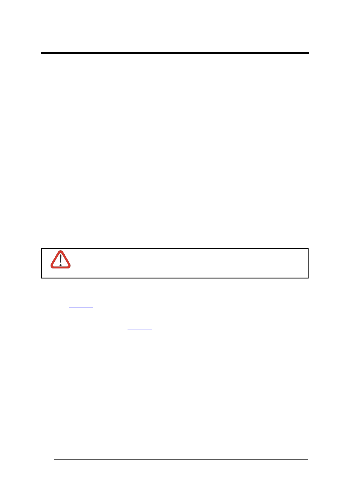
The laser light is visible to the human eye and is emitted from the window on the front of the
scanner (
Warning labels indicating exposure to laser light and the device classification are applied
onto the body of the scanner (
light.
Figure A, 7).
Figure A, 1).
vi
Page 7
Disconnect the power supply when opening
the device during maintenance or installation
to avoid exposure to hazardous laser light.
Complies with 21 CFR 1040.10
except for deviations pursuant
to Laser Notice N°50,
date June 24, 2007
The laser diode used in this device is
classified as a class 3B laser product
according to EN 60825-1 regulations and as a
Class IIIb laser product according to CDRH
regulations.
Any violation of the optic parts in particular
can cause radiation up to the maximum level
of the laser diode (35 mW at 630 to 680 nm).
LASER LIGHT
DO NOT STARE INTO BEAM
CLASS 2 LASER PRODUCT
MAX. OUTPUT RADIATION 1 mW
EMITTED WAVE LENGTH 630~680 nm
TO IEC 60825-1:1993+A1:1997+A2:2001
AVOID EXPOSURE LASER LIGHT
IS EMITTED FROM THIS APERTURE
Warning and Device Class Labels
CAUTION-CLASS 3B LASER LIGHT
WHEN OPEN AVOID EXPOSURE TO BEAM
Pat. US5992740, EP0789315B1
DATALOGIC AUTOMATION S.r.l.
Via S. Vitalino, 13 – 40012 Calderara di Reno
MADE IN ITALY-www.datalogic.com
FCC COMPLIANCE
Modifications or changes to this equipment without the expressed written approval of
Datalogic could void the authority to use the equipment.
This device complies with PART 15 of the FCC Rules. Operation is subject to the following
two conditions: (1) This device may not cause harmful interference, and (2) this device must
accept any interference received, including interference which may cause undesired
operation.
This equipment has been tested and found to comply with the limits for a Class A digital
device, pursuant to part 15 of the FCC Rules. These limits are designed to provide
reasonable protection against harmful interference when the equipment is operated in a
commercial environment. This equipment generates, uses, and can radiate radio frequency
energy and, if not installed and used in accordance with the instruction manual, may cause
harmful interference to radio communications. Operation of this equipment in a residential
area is likely to cause harmful interference in which case the user will be required to correct
the interference at his own expense.
POWER SUPPLY
This product is intended to be installed by Qualified Personnel only.
This accessory device is intended to be supplied by a UL Listed or CSA Certified Power Unit
with «Class 2» or LPS power source, which supplies power directly to the scanner via the 25pin connector.
CE COMPLIANCE
Warning:
This is a Class A product. In a domestic environment this product may cause radio
interference in which case the user may be required to take adequate measures.
vii
Page 8
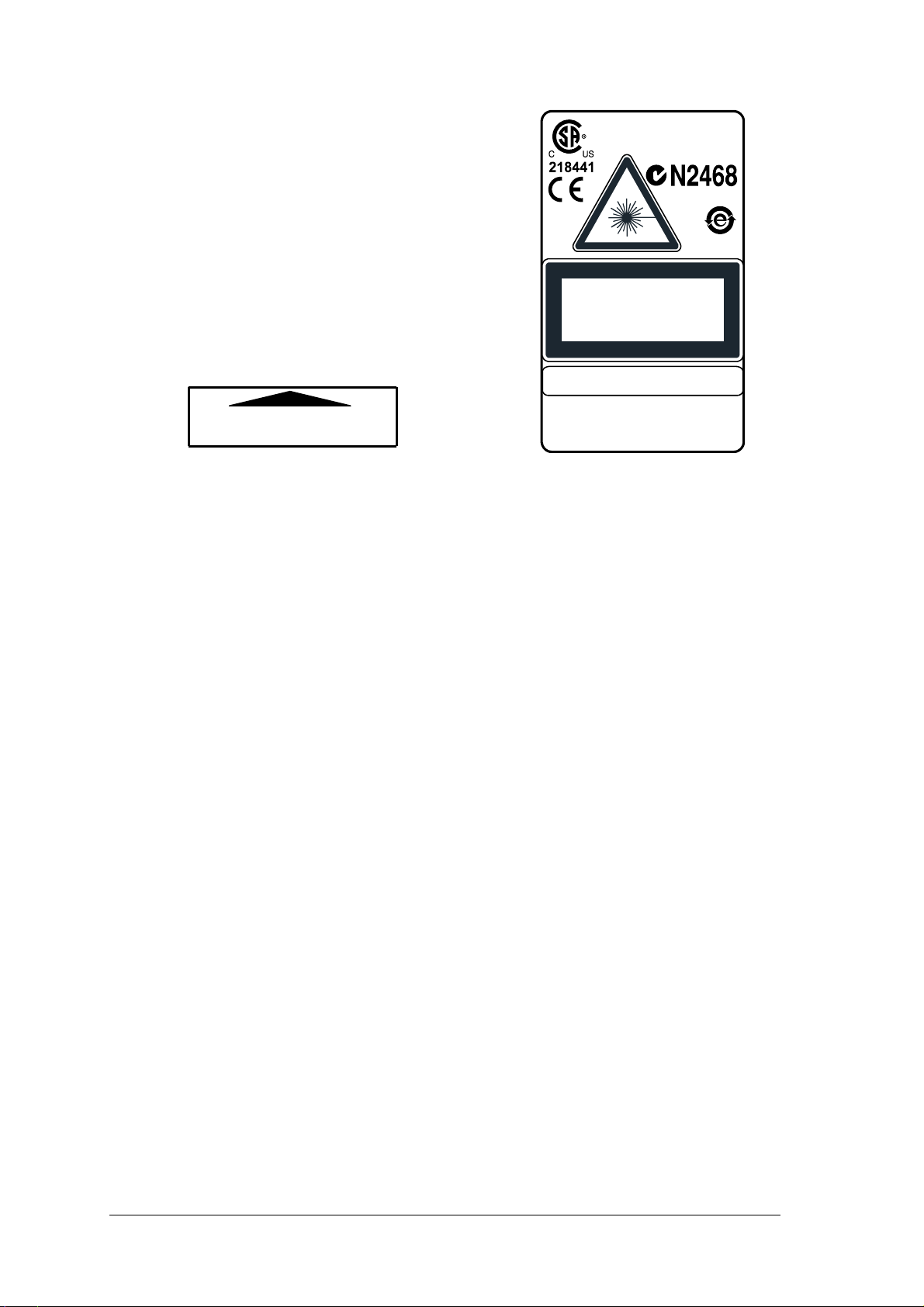
HANDLING
The DS2100N is designed to be used in an industrial environment and is built to withstand
vibration and shock when correctly installed, however it is also a precision product and
therefore before and during installation it must be handled correctly to avoid damage.
• avoid that the scanners hit one another causing damage. They should be handled
separately.
• avoid that the scanners are dropped (exceeding shock limits).
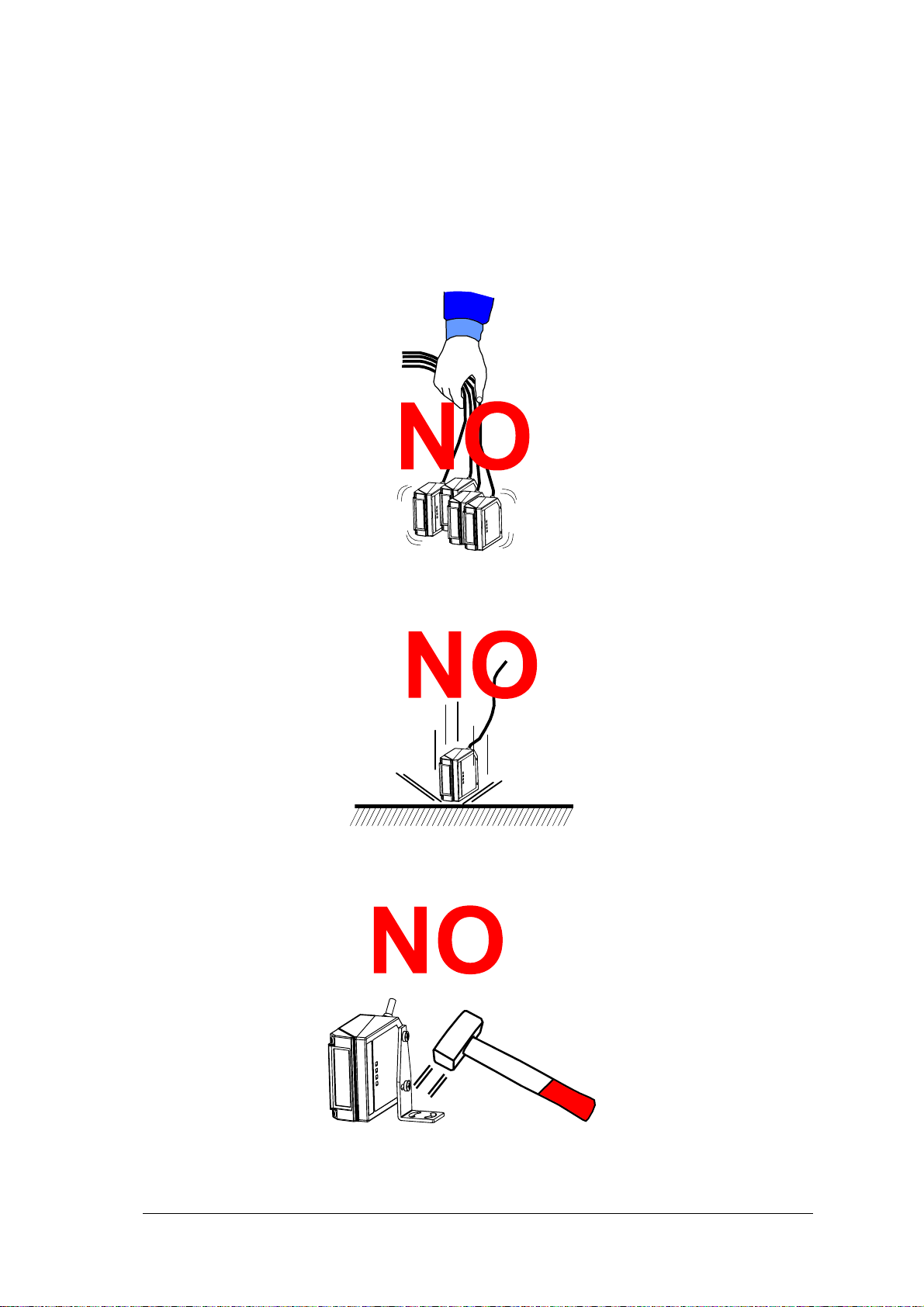
• do not fine tune the positioning by striking the scanner or bracket.
viii
Page 9

• do not weld the scanner into position which can cause electrostatic, heat or output
window damage.
• do not spray paint near the scanner which can cause output window damage.
ix
Page 10
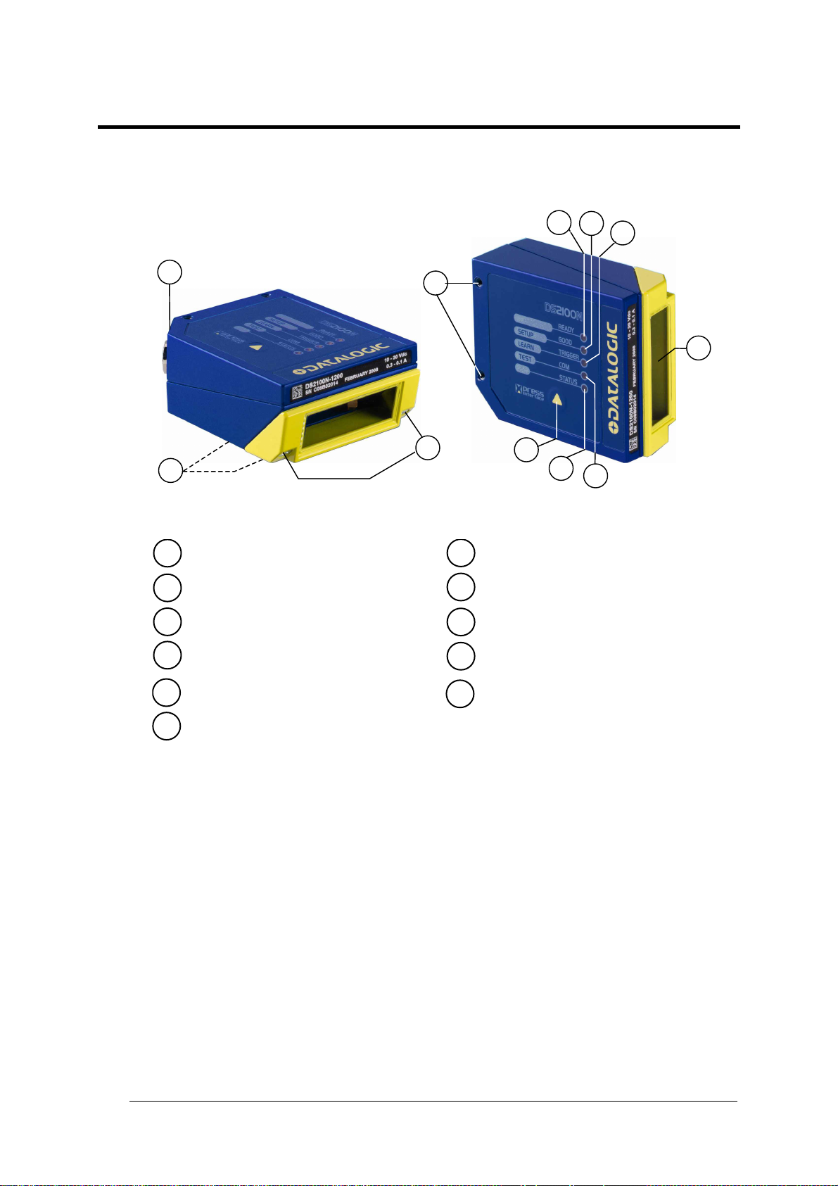
GENERAL VIEW
DS2100N
4
5
6
2
1
Warning and Device Class Labels
1
"POWER ON" LED
2
Mounting Holes
3
"READY" LED
4
3
11
Figure A
10
9
8
Laser Beam Output Window
7
"COM" LED
8
"STATUS" LED
9
Push Button
10
7
"GOOD" LED
5
"TRIGGER" LED
6
Accessory Mounting Holes
11
x
Page 11
RAPID CONFIGURATION
1
1 RAPID CONFIGURATION
This chapter illustrates a Stand Alone application. For other types of
installations, such as ID-NET™, Fieldbus, Pass-Through, Multiplexer Layout,
etc., refer to chapters 4, 5 and 6. For complete scanner configuration using the
NOTE
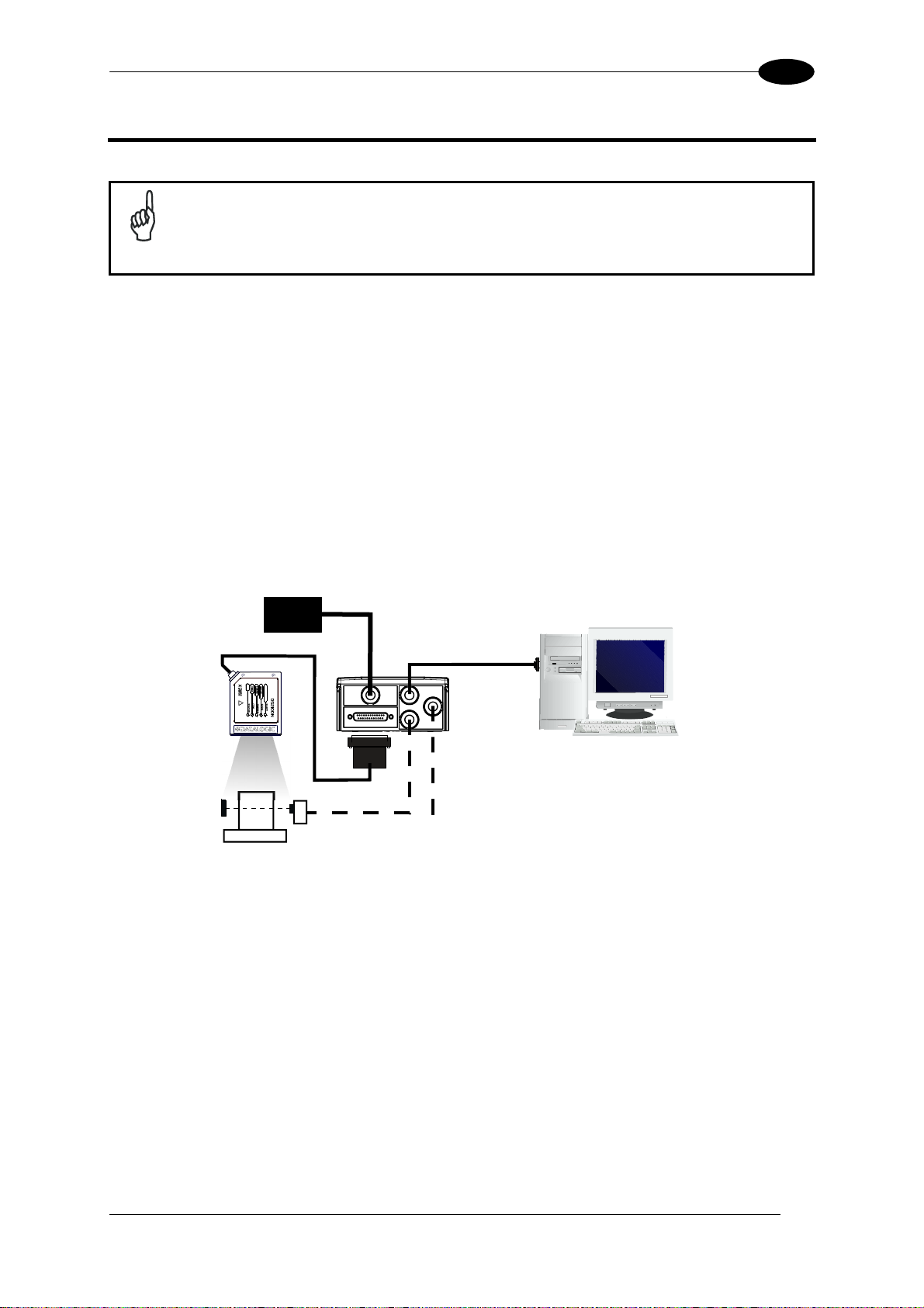
STEP 1 – CONNECT THE SYSTEM
To connect the system in a Stand Alone configuration, you need the hardware indicated in
Figure 1.
In this layout the data is transmitted to the Host on the main serial interface.
In Local Echo communication mode, data is transmitted on the RS232 auxiliary interface
independently from the main interface selection.
When On-Line Operating mode is used, the scanner is activated by an External Trigger
(photoelectric sensor) when the object enters its reading zone.
Genius™ configuration program, refer to the Context-Sensitive Help On-Line.
DS2100N
PG 6000
MAIN
CBX100/500
P.S.*
Figure 1 – DS2100N in Stand Alone Layout
I/O, AUX
Host
* Presence Sensor
(for On-Line mode)
1
Page 12
1
DS2100N REFERENCE MANUAL
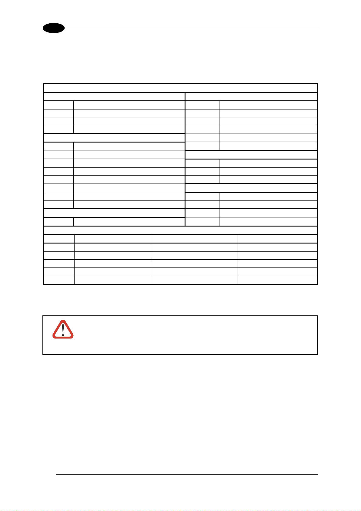
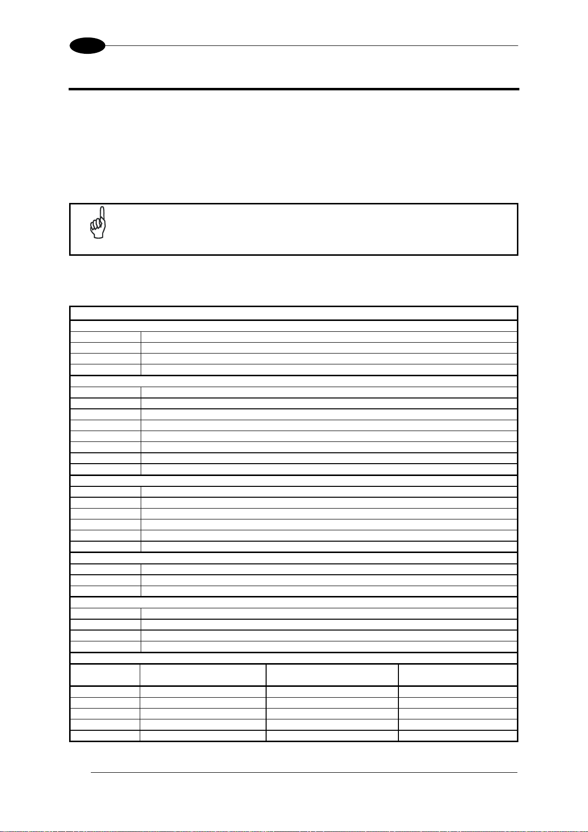
CBX100/500 Pinout for DS2100N
The table below gives the pinout of the CBX100/500 terminal block connectors. Use this
pinout when the DS2100N reader is connected by means of the CBX100/500:
CBX100/500 Terminal Block Connectors
Input Power Outputs
Vdc Power Supply Input Voltage + +V Power Source - Outputs
GND Power Supply Input Voltage - -V Power Reference - Outputs
Earth Protection Earth Ground O1+ Output 1 +
O1- Output 1 -
Inputs
+V Power Source – External Trigger O2- Output 2 I1A External Trigger A (polarity insensitive)
I1B External Trigger B (polarity insensitive) TX Auxiliary Interface TX
-V Power Reference – External Trigger RX Auxiliary Interface RX
+V Power Source – Inputs SGND Auxiliary Interface Reference
I2A Input 2 A (polarity insensitive)
I2B Input 2 B (polarity insensitive) REF Network Reference
-V Power Reference – Inputs ID+ ID-NET™ network +
Shield
Shield Network Cable Shield
Main Interface
RS232 RS485 Full-Duplex RS485 Half-Duplex
TX TX+ RTX+
RTS TX- RTX RX *RX+
CTS *RX-
SGND SGND SGND
* Do not leave floating, see par. 4.2.2 for connection details.
O2+ Output 2 +
Auxiliary Interface
ID-NET™
ID- ID-NET™ network -
CAUTION
2
Do not connect GND, SGND and REF to different (external) ground
references. GND, SGND and REF are internally connected through filtering
circuitry which can be permanently damaged if subjected to voltage drops
over 0.8 Vdc.
Page 13
RAPID CONFIGURATION
1
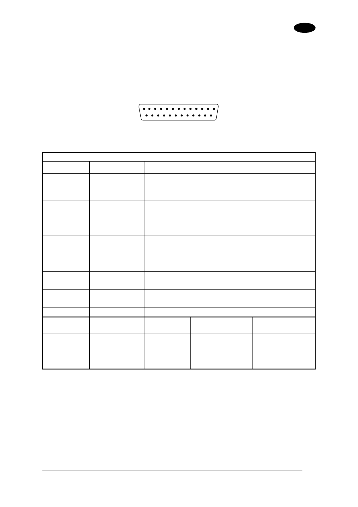
25-pin Connector Pinout for DS2100N
The table below gives the pinout of the 25-pin male D-sub connector for connection to the
power supply and input/output signals. Use this pinout when the DS2100N reader is
connected by means of the 25-pin connector:
1
Figure 2 - 25-pin Male D-sub Connector
25-pin D-sub male connector pinout
Pin Name Function
13, 9 Vdc Power supply input voltage +
25, 7 GND Power supply input voltage -
1 CHASSIS Cable shield connected to chassis
18 I1A External Trigger A (polarity insensitive)
19 I1B External Trigger B (polarity insensitive)
6 I2A Input 2 A (polarity insensitive)
10 I2B Input 2 B (polarity insensitive)
8 O1+ Output 1 +
22 O1- Output 1 11 O2+ Output 2 +
12 O2- Output 2 20 RX Auxiliary RS232 RX
21 TX Auxiliary RS232 TX
23 ID+ ID-NET™ network +
24 ID- ID-NET™ network -
14, 15, 16, 17 NC Not Connected
Pin Name RS232
2 TX TX+ RTX+
3 RX *RX+
4 RTS TX- RTX-
5
MAIN INTERFACE
(SW SELECTABLE)
CTS *RX-
* Do not leave floating, see par. 5.2.2 for connection details.
13
2514
RS485
Full-Duplex
RS485
Half-Duplex
3
Page 14

1
DS2100N REFERENCE MANUAL
STEP 2 – MOUNTING AND POSITIONING THE SYSTEM
1. To mount the DS2100N, use the mounting bracket to obtain the most suitable position for
the reader as shown in the figures below.
Skew
Tilt
Pitch
Skew
Figure 3 - Positioning with Mounting Bracket
2. When mounting the DS2100N take into consideration these three ideal label position angles:
Skew 10° to 30°, Tilt 0° and Pitch 0°.
S
T
Assure at least 10° Minimize
Figure 4 –Skew and Tilt Angles
P
Minimize
Figure 5 – Pitch Angle
3. Refer to the Reading Diagrams in par. 7.4 to decide the distance your scanner should be
positioned at.
4
Page 15
RAPID CONFIGURATION
1
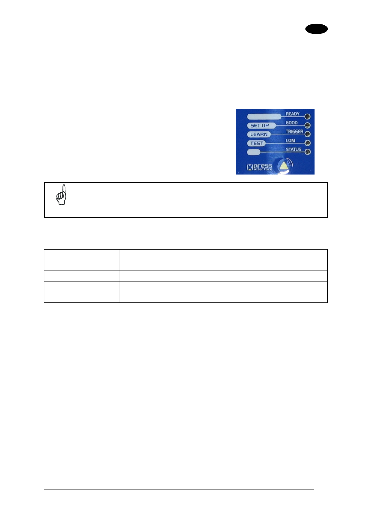
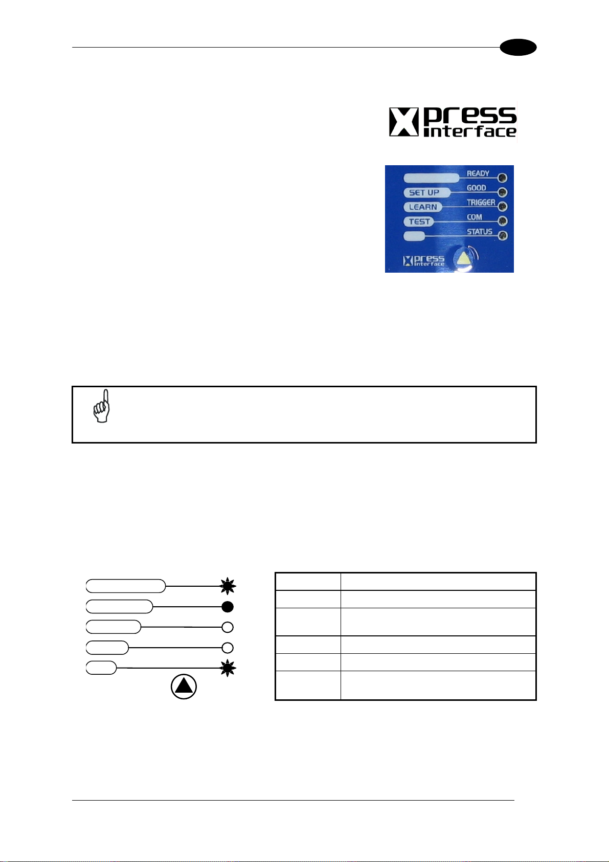
STEP 3 – X-PRESS™ CONFIGURATION
X-PRESS™ is the intuitive Human Machine Interface designed to improve ease of
installation and maintenance.
Status and diagnostic information are clearly presented by means of the five colored LEDs,
whereas the single push button gives immediate access to the following relevant functions:
• AutoSetup to self-optimize and auto-configure
reading performance in demanding applications
• AutoLearn to self-detect and auto-configure for
reading unknown barcodes (by type and length)
• Test Mode with bar-graph visualization to check
static reading performance
If using the OM2000N accessory, when entering the X-PRESS™ interface, the
Oscillating Mirror remains in the default fixed position (-15°) in order to make
NOTE
barcode reading easier while performing the X-PRESS™ functions.
The colors and meaning of the five LEDs are illustrated in the following table:
READY (green) This LED indicates the device is ready to operate.
GOOD (green) This LED confirms successful reading.
TRIGGER (yellow) This LED indicates the status of the reading phase.
COM (yellow) This LED indicates active communication on main serial port. *
STATUS (red) This LED indicates a NO READ result.
* When connected to a Fieldbus network through the CBX500, the COM LED is always active, even in the
absence of data transmission, because of polling activity on the Fieldbus network.
During the reader startup (reset or restart phase), all the LEDs blink for one second.
On the back of the reader near the cable, the “POWER ON” LED indicates the laser scanner
is correctly powered.
5
Page 16
1
T
DS2100N REFERENCE MANUAL
Auto Learn
If you are configuring your scanner using X-PRESS™, you must start with the Auto Learn
procedure.
1. Enter the Auto Learn function by holding the X-PRESS™ push button pressed until the
LEARN LED is on.
2. Release the button to enter the Auto Learn function.
Once entered, the reader starts a procedure to automatically detect and recognize
barcodes (by type and length), which are presented to it (*). The laser turns on and the
LEARN LED blinks to indicate the ongoing process.
The procedure is as follows:
A) place the desired barcode on the
READY
SETUP
LEARN
TES
Figure 6 – X-PRESS™ Interface: Auto Learn Function
GOOD
TRIGGER
COM
STATUS
green
green
yellow
yellow
red
scanline.
B) wait until the LEARN LED stays
steady on (indicating the reader
has detected the barcode).
C) repeat, if needed, the above two
steps to program up to 10 different
barcodes (the LEARN LED returns
to the blinking state for the next
code). If more than one barcode is
detected in the scan line, the Multi
Label mode is enabled (refer to the
“2K/4K Family Software
Configuration Parameter Guide”
Help file).
3. Exit the process by pressing the X-PRESS™ push button once. The scanner will restart
at the end of the process, and then the detected barcodes are automatically configured in
scanner memory.
If the barcode cannot be read because of low contrast or excessive ambient
light, you can perform the AutoSetup function to optimize the optical
NOTE
parameters. Then you can perform AutoLearn to recognize the barcode
symbology.
On exit from Autolearn, the following parameters are forced: Code
NOTE
Combination = Single Label, Reading Mode = Linear. If necessary, these
parameters can be changed through Genius™.
* In case of Programming Barcodes (refer to the “ID-NET™: Programming Barcodes And Setup Procedure”
document in the product CD).
6
Page 17
RAPID CONFIGURATION
T
1
Auto Setup (Optional)
At the end of the Auto Learn procedure, you have the possibility to follow the Auto Setup
procedure to set up the reading parameters.
1. Enter the Auto Setup function by holding the X-PRESS™ push button pressed until the
SETUP LED is on.
2. Release the button to enter the Auto Setup function.
3. Once entered, if a barcode label is positioned in front of the scanline, the scanner
automatically performs the optimal setup of the reading parameters for that specific
barcode.
READY
SETUP
LEARN
TES
Figure 7 – X-PRESS™ Interface: Auto Setup Function
GOOD
TRIGGER
COM
STATUS
green
green
yellow
yellow
red
This procedure ends either when the barcode is successfully decoded or after a timeout of
about 7 (seven) seconds.
The scanner will restart at the end of the process, and then the optimized reading
parameters for that barcode are automatically configured in scanner memory.
The procedure is as follows:
A) place the desired barcode on the
scanline.
B) enter the AutoSetup function (the
laser turns on and the SETUP LED
blinks to indicate the ongoing
process)
C) wait until the SETUP LED stays
steady on (indicating the reader
has detected the barcode)
If your application has been configured using X-PRESS™, go to STEP 5.
NOTE
Reset Scanner to Factory Default (Optional)
If it ever becomes necessary to reset the scanner to the factory default values, you can
perform this procedure by holding the X-PRESS™ push button pressed while powering up
the scanner. At the end of the procedure (about 5-6 seconds), the Configuration and
Environmental parameters are reset, and all LEDs blink simultaneously 3 times. If connected
through a CBX500 with display module, the message "Default Set" is shown on the display.
7
Page 18
1
DS2100N REFERENCE MANUAL
STEP 4 – INSTALLING GENIUS™ CONFIGURATION PROGRAM
Genius
• Wizard approach for new users;
• Multi-language version;
• Defined configuration directly stored in the reader;
• Communication protocol independent from the physical interface allowing to consider the
To install Genius™, turn on the PC that will be used for the configuration, running
Windows 98, 2000/NT, XP or Vista, then insert the Genius™ CD-ROM, wait for the CD to
autorun and follow the installation procedure.
This configuration procedure assumes scanner connection to a CBX100/500. Genius™,
running on a laptop computer, is connected to the scanner auxiliary port through the
CBX100/500 9-pin connector. To communicate with the scanner, Genius™ performs an auto
baudrate detection starting from its default parameters which are 115200, 8, N, 1. These
parameters can also be set in the Genius™ Tools>Options>Communications window.
™
is a Datalogic scanner configuration tool providing several important advantages:
reader as a remote object to be configured and monitored.
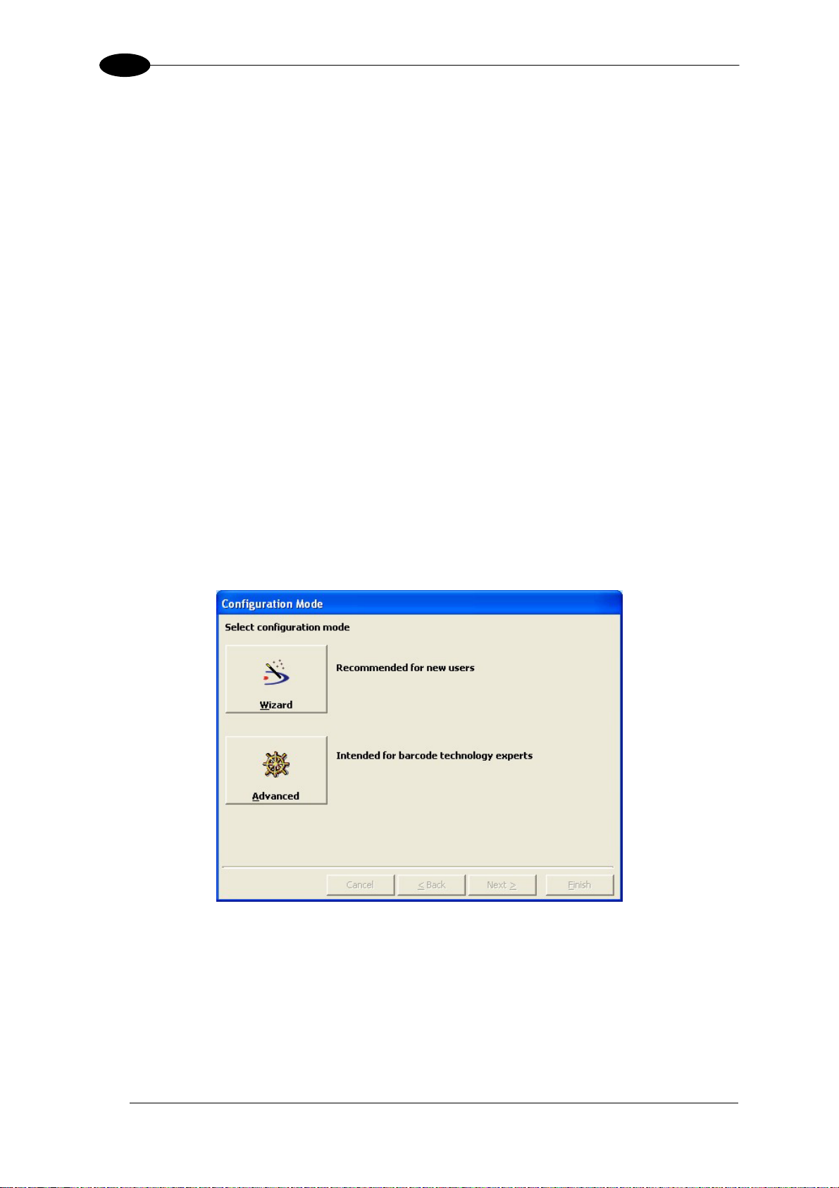
Wizard for Quick Reader Setup
After installing the Genius™ software program the following window appears asking the user
to choose the desired configuration level.
Figure 8 - Genius™ Wizard Opening Window
The Wizard option is advised for rapid configuration or new users, since it shows a step-bystep scanner configuration.
8
Page 19
RAPID CONFIGURATION
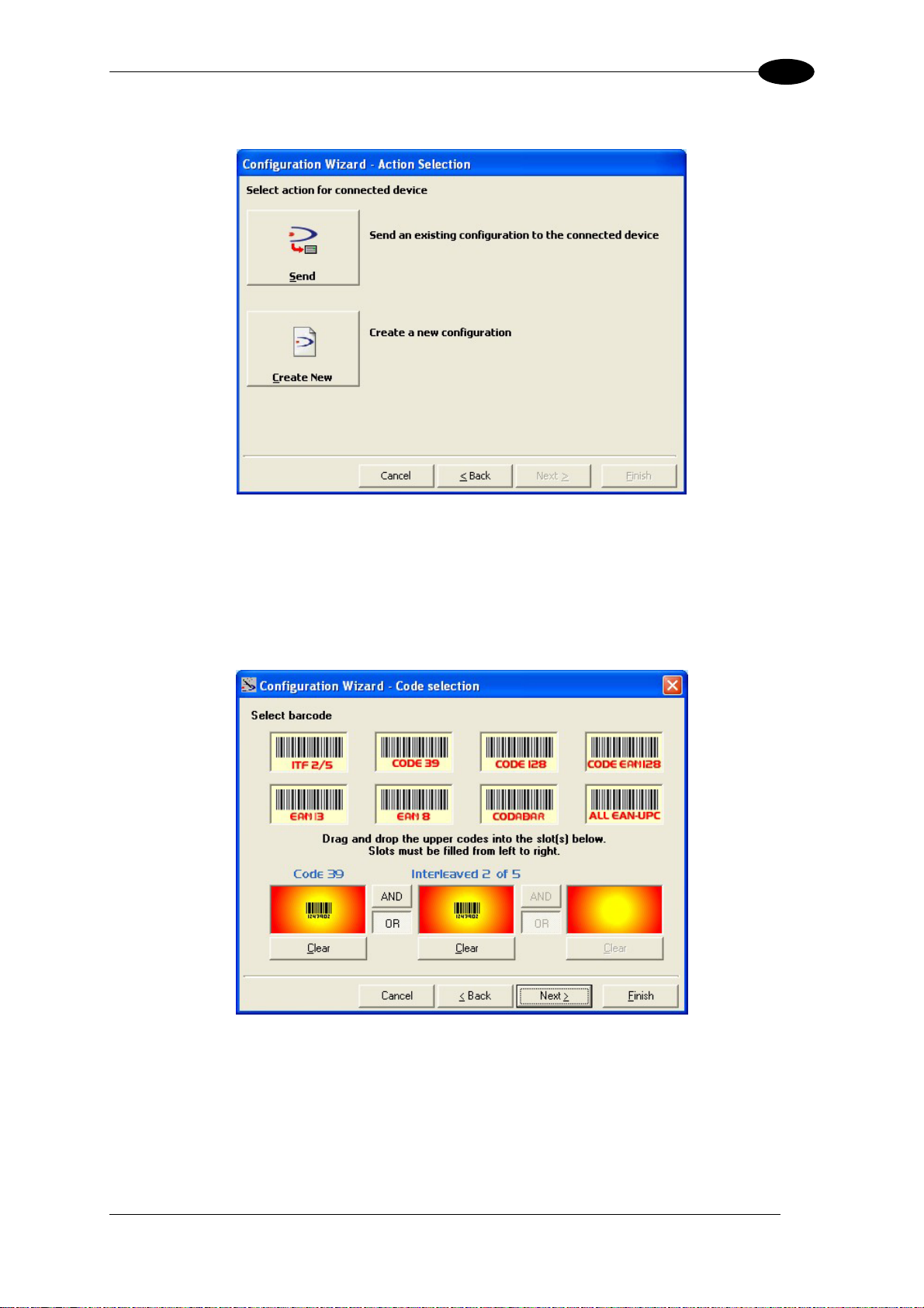
1. Select the Create a new configuration button.
You will be guided through the configuration being asked to define the following
parameters:
a. Barcode selection and definition
1
9
Page 20
1
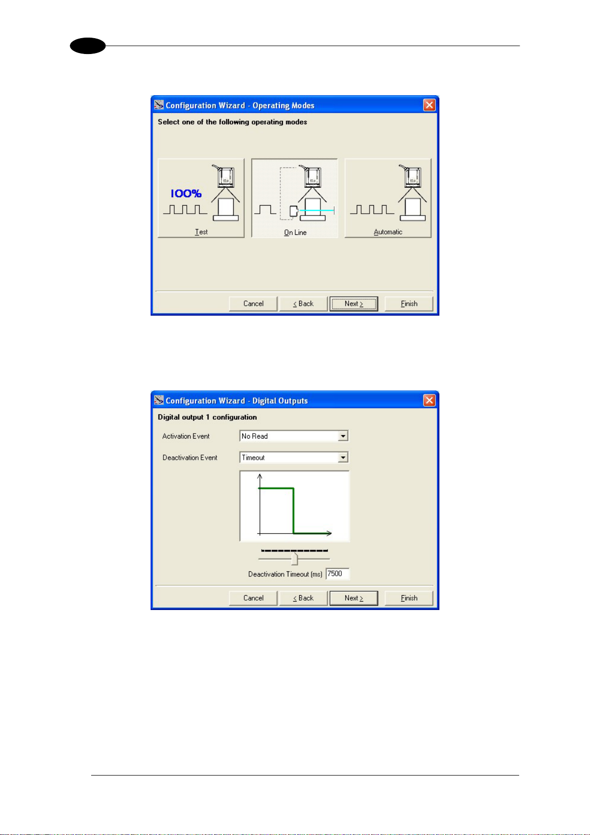
b. Operating mode selection and definition
c. Digital Outputs configuration
DS2100N REFERENCE MANUAL
10
Page 21
RAPID CONFIGURATION
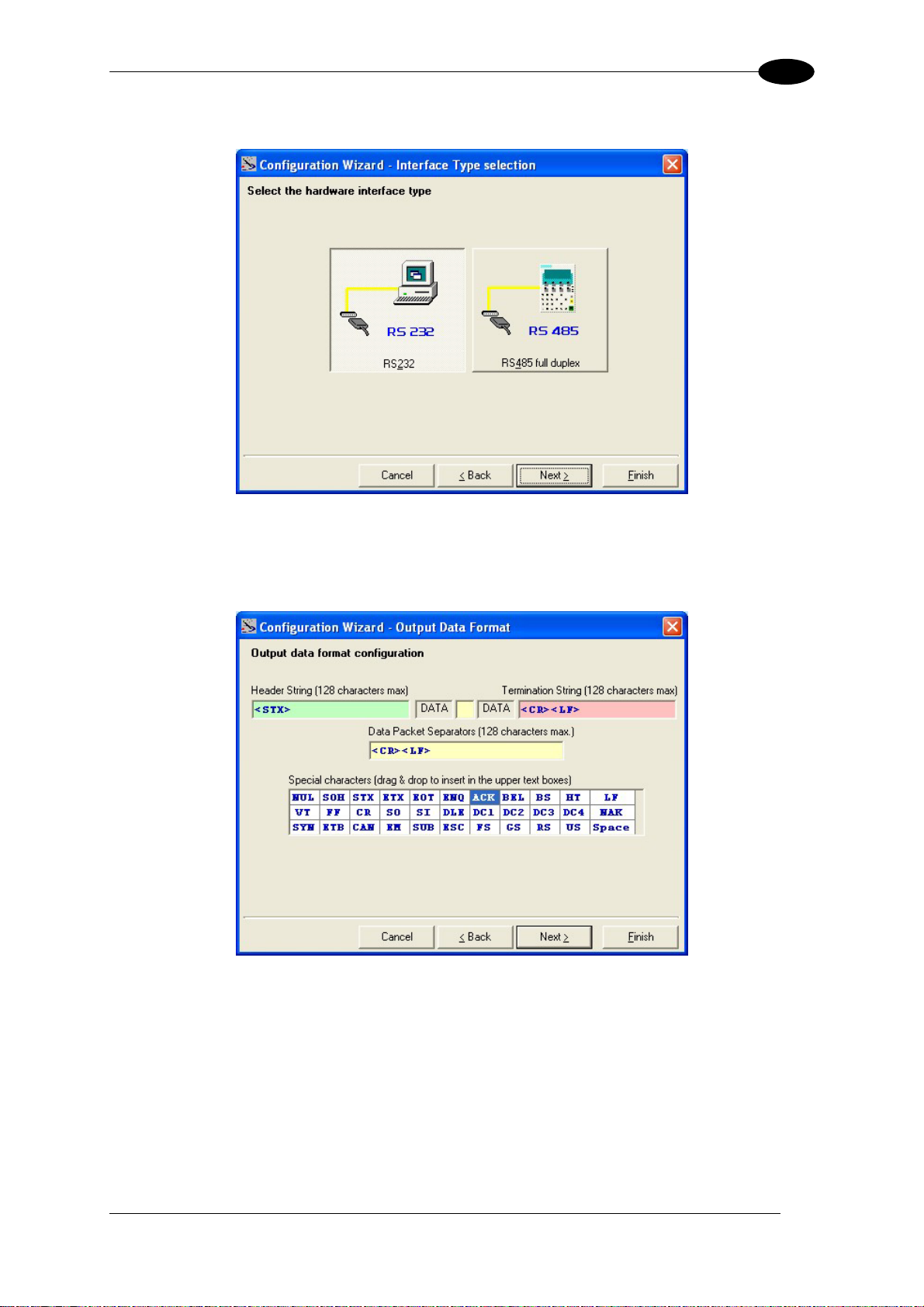
d. Hardware interface selection
e. Output data format configuration
1
The On Line operating Mode requires the reader to be connected to an External
Trigger/Presence Sensor using I1A and I1B inputs.
The Automatic operating mode does not require connection to an external Presence
Sensor. When working in this mode the reader is continuously scanning, while the
reading phase is activated each time a barcode enters the reader reading zone. The
reader stops reading after an N number of scans without a code. Barcode characters
are transmitted on the serial interface. In case of a failed reading phase no message is
sent to the host computer.
11
Page 22
1
DS2100N REFERENCE MANUAL
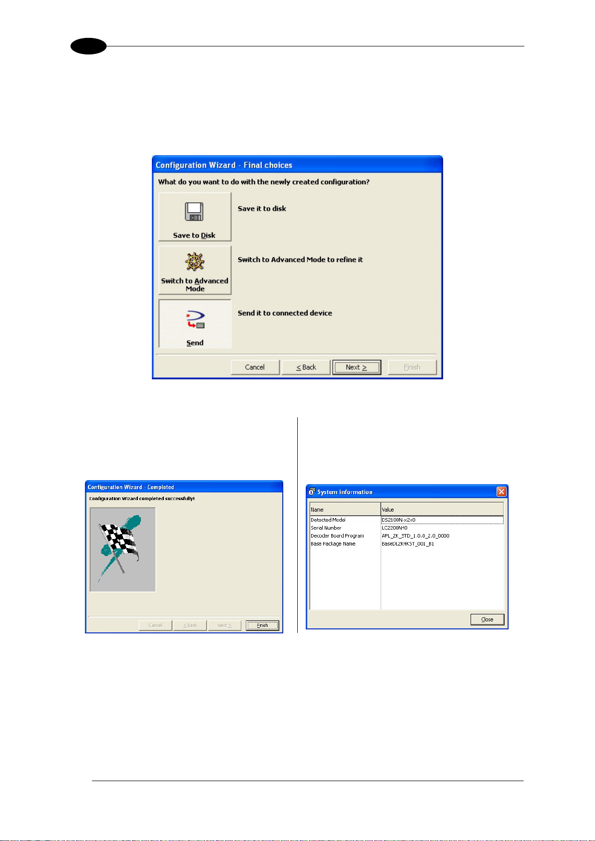
2. After defining the parameter values the following window appears allowing to complete
the reader configuration as follows:
• Saving the configuration to disk;
• Switching to Advanced mode;
• Sending the configuration to the scanner.
3. After sending the configuration to the
scanner you have completed the
configuration process.
4. By clicking Finish, the System
Information window will be displayed
with specific information concerning the
scanner.
12
Page 23
RAPID CONFIGURATION
1
STEP 5 – TEST MODE
Use a code suitable to your application to test the system. Alternatively, you can use the
Datalogic Test Chart (Code 39, Code Interleaved 2/5).
1. Enter the Test mode function by holding the X-PRESS™ push button pressed until the
TEST LED is on.
2. Release the button to enter the Test mode function.
Once entered, the Bar-Graph on the five LEDs is activated and if the scanner starts
reading barcodes the Bar-Graph shows the Good Read Rate. In case of no read
condition, only the STATUS LED is on and blinks.
SETUP
LEARN
TEST
READY
GOOD
TRIGGER
COM
STATUS
green
green
yellow
yellow
red
Figure 9 – X-PRESS™ Interface: Test Mode Function
3. To exit the Test Mode, press the X-PRESS™ push button once.
By default, the Test Mode exits automatically after two minutes.
NOTE
13
Page 24
1
DS2100N REFERENCE MANUAL
ADVANCED SCANNER CONFIGURATION
For further details on advanced product configuration, refer to the complete Reference
Manual on the installation CD-ROM or downloadable from the web site through this link:
www.automation.datalogic.com/ds2100n.
The following are alternative or advanced scanner configuration methods:
Host Mode Programming
The scanner can also be configured from a host computer using the Host Mode
programming procedure, by commands via the serial interface. See the Host Mode
Programming file on the CD-ROM.
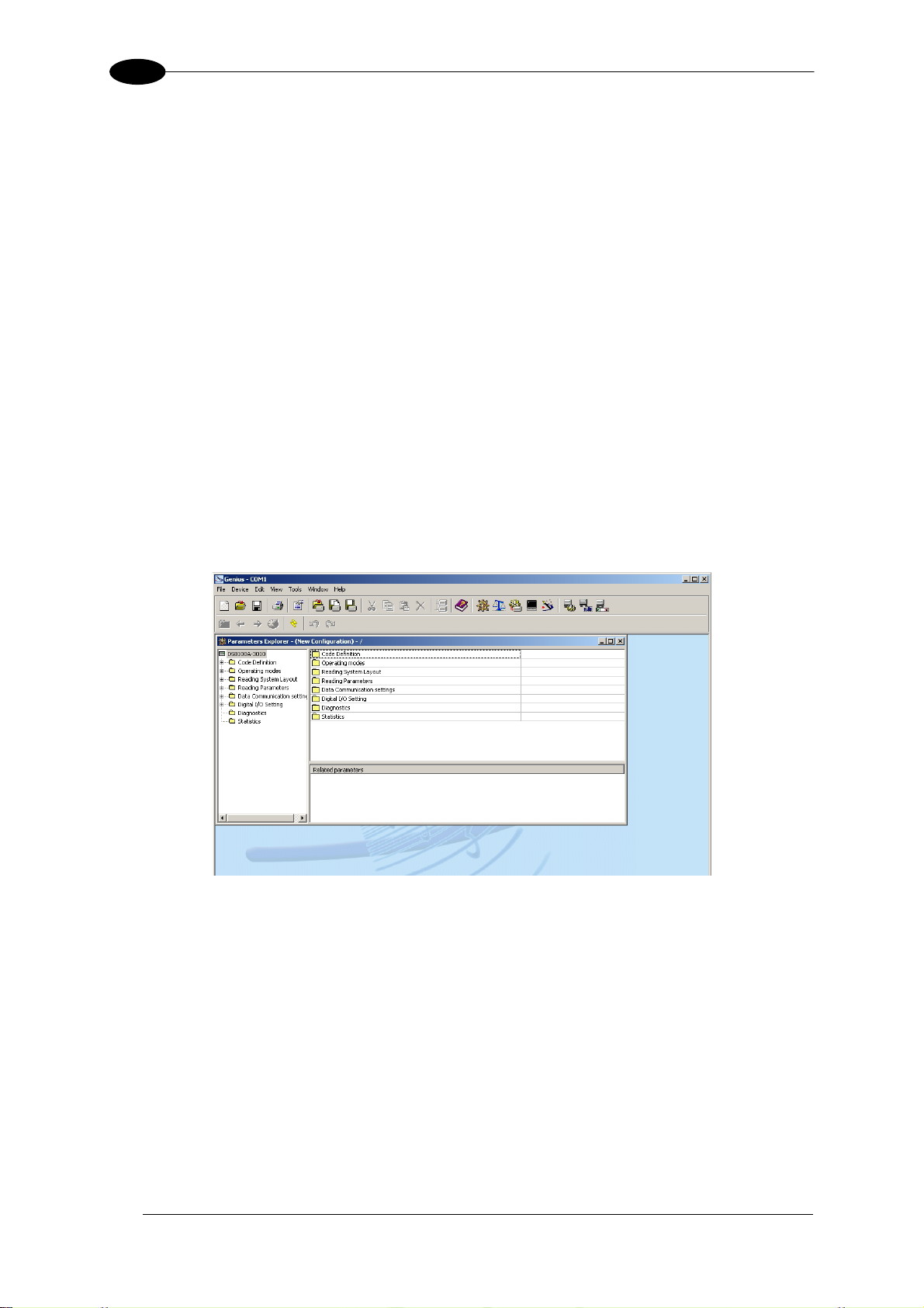
Advanced Genius™ Configuration
The ADVANCED selection available when starting the Genius™ program is addressed to
expert users being able to complete a detailed scanner configuration. By choosing this option
it is possible either to start a new scanner configuration or to open and modify an old one.
The desired parameters can be defined in the following window, similar to the MS Explorer:
Figure 10 - Genius™ Parameter Explorer Window
Alternative Layouts
• The ID-NET™ is a built-in high-speed interface dedicated for high-speed scanner
interconnection. ID-NET™ is in addition to the Main and Auxiliary serial interfaces.
If you need to install an ID-NET™ network refer to the DS2100N Reference Manual.
The scanner can also be configured by reading programming barcodes. See the IDNET™ Setup Procedure Using Programming Barcodes printable from the CD-ROM.
• If you need to install a Pass-Through network refer to the DS2100N Reference Manual.
• If you need to install a Multiplexer network refer to the DS2100N Reference Manual.
• If you need to install an RS232 Master/Slave (for backward compatibility) refer to the
DS2100N Reference Manual.
14
Page 25

INTRODUCTION
2
2 INTRODUCTION
2.1 PRODUCT DESCRIPTION
The DS2100N laser scanner satisfies the most advanced needs of a wide range of users. It
has been developed focusing on the realistic requirements of its target market. The
outstanding result is an extremely compact, cost-effective and easy to use industrial scanner.
Standard Application
Program
Custom Application
Programs
Some of the main features of DS2100N are listed below:
A standard application program is factory-loaded onto the
DS2100N. This program controls barcode reading, serial port
interfacing, data formatting and many other operating and control
parameters.
It is completely configurable from a host computer through the
Genius™ utility program provided on CD with the scanner, or via
the serial interface (Genius™ based Host Mode Programming).
If the Standard Application Program does not meet your
requirements, please contact your local Datalogic distributor.
• ACB (Advanced Code Builder)
• small dimensions and light weight
• software programmable scanning speed on all models
• linear and raster version
• completely configurable via serial interface (Genius™)
• 3 serial communication interfaces (Main, Auxiliary, ID-NET™)
• supply voltage from 10 to 30 Vdc
• reads all popular codes
• test mode to verify the reading features and exact positioning of the scanner without the
need for external tools
• programmable in 4 different operating modes to suit the most various barcode reading
system requirements
• code verifier
• low power consumption
The DS2100N uses a solid-state laser diode as a light source; the light emitted has a
wavelength between 630 and 680 nm. Refer to the section “Safety Precautions” at the
beginning of this manual for information on laser safety.
The protection class of the enclosure is IP65, the reader is therefore suitable for industrial
environments where high protection against harsh external conditions is required.
15
Page 26
2
A
2.1.1 Indicators
The five LEDs on the side of the scanner (
READY
(green)
This LED indicates the device is ready to operate.
DS2100N REFERENCE MANUAL
Figure A) indicate the following:
GOOD
TRIGGER
COM
STATUS
(green)
(yellow)
(yellow)
(red)
This LED confirms successful reading.
This LED indicates the status of the reading phase. *
This LED indicates active communication on main serial port. **
This LED indicates a NO READ result.
* In On-Line mode the TRIGGER LED corresponds to the active reading phase signaled by the Presence Sensor.
In Automatic and Continuous modes the TRIGGER LED is always on indicating that the reader is ready to read a
code.
** When connected to a Fieldbus network through the CBX500, the COM LED is always active, even in the
absence of data transmission, because of polling activity on the Fieldbus network.
During the reader startup (reset or restart phase), all the LEDs blink for one second.
On the back of the reader near the cable, the “POWER ON” LED indicates the laser scanner
is correctly powered.
2.2 ID-NET™
The ID-NET™ is a built-in high-speed interface dedicated for highspeed scanner interconnection. The ID-NET™ is in addition to the
Main and Auxiliary serial interfaces.
The following network configurations are available:
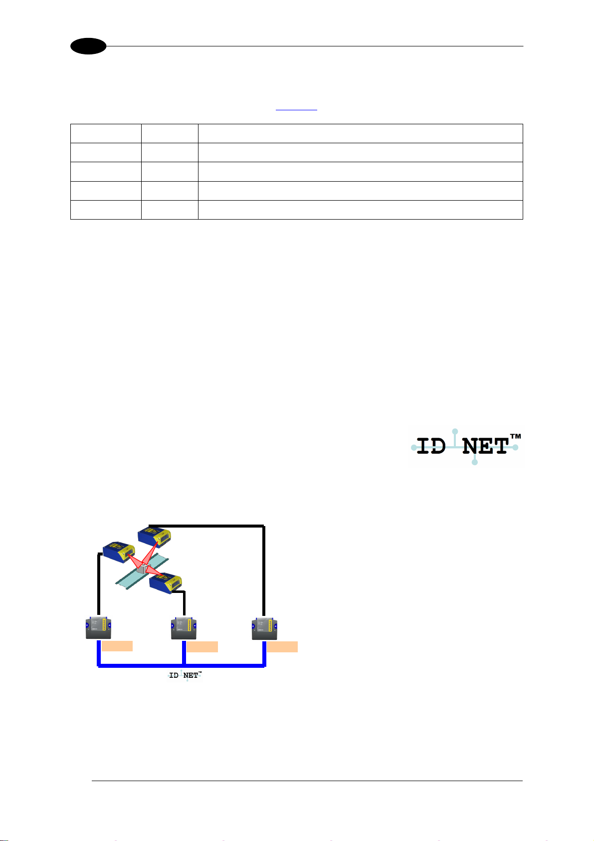
ID-NET™ M/S Synchronized: Single station – multiple scanners
CBX100
CBX100
CBX100
ID-NET™ interface allows local connection
of multiple scanners reading different sides
of the same target. All scanners share a
single presence sensor and
activate/deactivate simultaneously.
t the end of each reading phase a single
data message is transmitted to the host.
Thanks to ID-NET™, data communication
among scanners is highly efficient so that
an immediate result will be available.
16
Page 27
INTRODUCTION
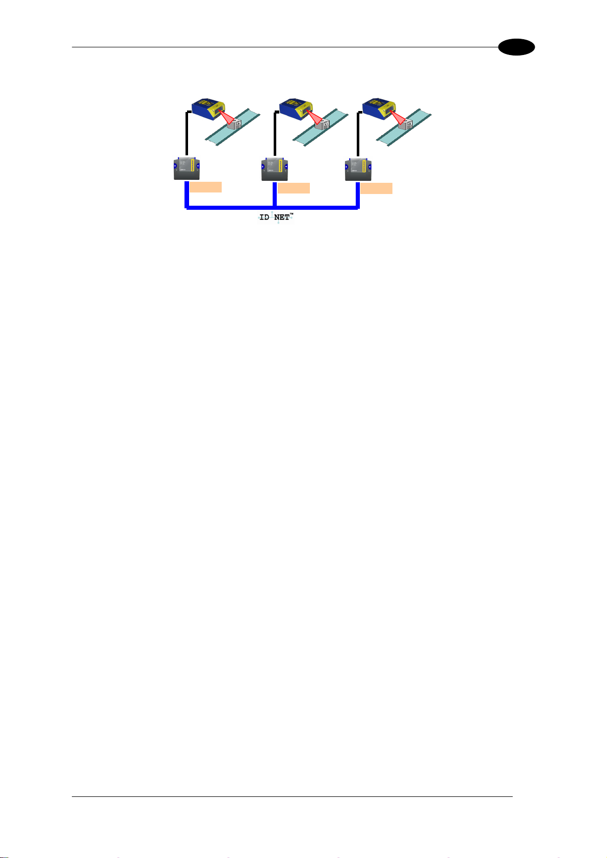
ID-NET™ M/S Multidata: Multiple stations – single scanner
2
CBX100
CBX100
CBX100
ID-NET™ interface allows connection of scanners reading objects placed on independent
conveyors. All scanners are typically located far away from each other and they use a
dedicated presence sensor.
At the end of each reading phase, each scanner transmits its own data message to the host.
Thanks to ID-NET™, data collection among readers is accomplished at a high speed without
the need of external multiplexing device. This leads to an overall cost reduction and to a
simple system wiring.
17
Page 28

2
DS2100N REFERENCE MANUAL
2.2.1 How To Setup/Configure the Scanner Network
A complete ID-NET™ scanner network can be rapidly setup, as follows:
Mounting & Connection
1. Mechanically mount/install all the readers (refer to par. 3.2 and 3.3).
2. Wire ID-NET™ (refer to par. 4.3 or 5.3).
3. Connect the planned Master scanner to a PC by means of the Genius™ configuration
software.
4. Power up the entire system.
Configuration
1. Launch Genius™.
2. From the Genius™ Device Menu select “Local Device Network Settings” and program the
Role of the Master scanner (Synchronized or Multidata).
This procedure requires the Network Baud Rate be the same for all Slaves and Master,
(500 kbs is the default value). It can be changed after network setup using Genius™
through the Master scanner. See also the alternative procedure in the note below.
3. At the prompt to "Send updated Network configuration to the Local Device" (Master)
choose "Yes".
4. Then run the NET-AUTOSET procedure from the Icon in the Devices Area. Genius™
sets all slave scanners according to the Master Role (Synchronized or Multidata), and
assigns each a random address. If necessary, this address can be changed through the
Network Wizard.
5. Configure the System parameters via Genius™.
6. If using the CBX connection box equipped with a BM100 Backup module, perform
System Backup at the Master.
The scanner network is ready.
If necessary, the ID-NET™ baudrate can be set individually on each Slave
scanner to match the Master. Connect each Slave to Genius™ and set the
NOTE
NOTE
Reading System Layout > Network Baudrate parameter. Then follow the
procedure above.
An alternative method of programming scanner address and role assignment
can be accomplished by using the “Connectivity Programming Barcodes”
(refer to the “ID-NET™ Setup Procedure Using Programming Barcodes”
document on the product CD).
18
Page 29
INTRODUCTION
T
Y
2.3 X-PRESS™ HUMAN MACHINE INTERFACE
X-PRESS™ is the intuitive Human Machine Interface
designed with the precise goal of improving ease of
installation and maintenance.
Status and diagnostic information are clearly presented
by means of five-colored LEDs, whereas the single
multi-function key gives immediate access to relevant
functions:
• Autosetup to self-optimize reading performance
in demanding applications
• Autolearn to self-detect unknown barcodes
2
• Test Mode with bar-graph visualization to check
static reading performance
X-PRESS™ is the common interface adopted in all new products: “You learn one, you can
use them all”.
The colors and meaning of the five LEDs when in the one of the operating modes (On-Line,
Automatic or Continuous) are illustrated in par 2.1.1.
The X-PRESS™ functions do not work if the motor or laser are turned off,
see chp. 9 for details.
NOTE
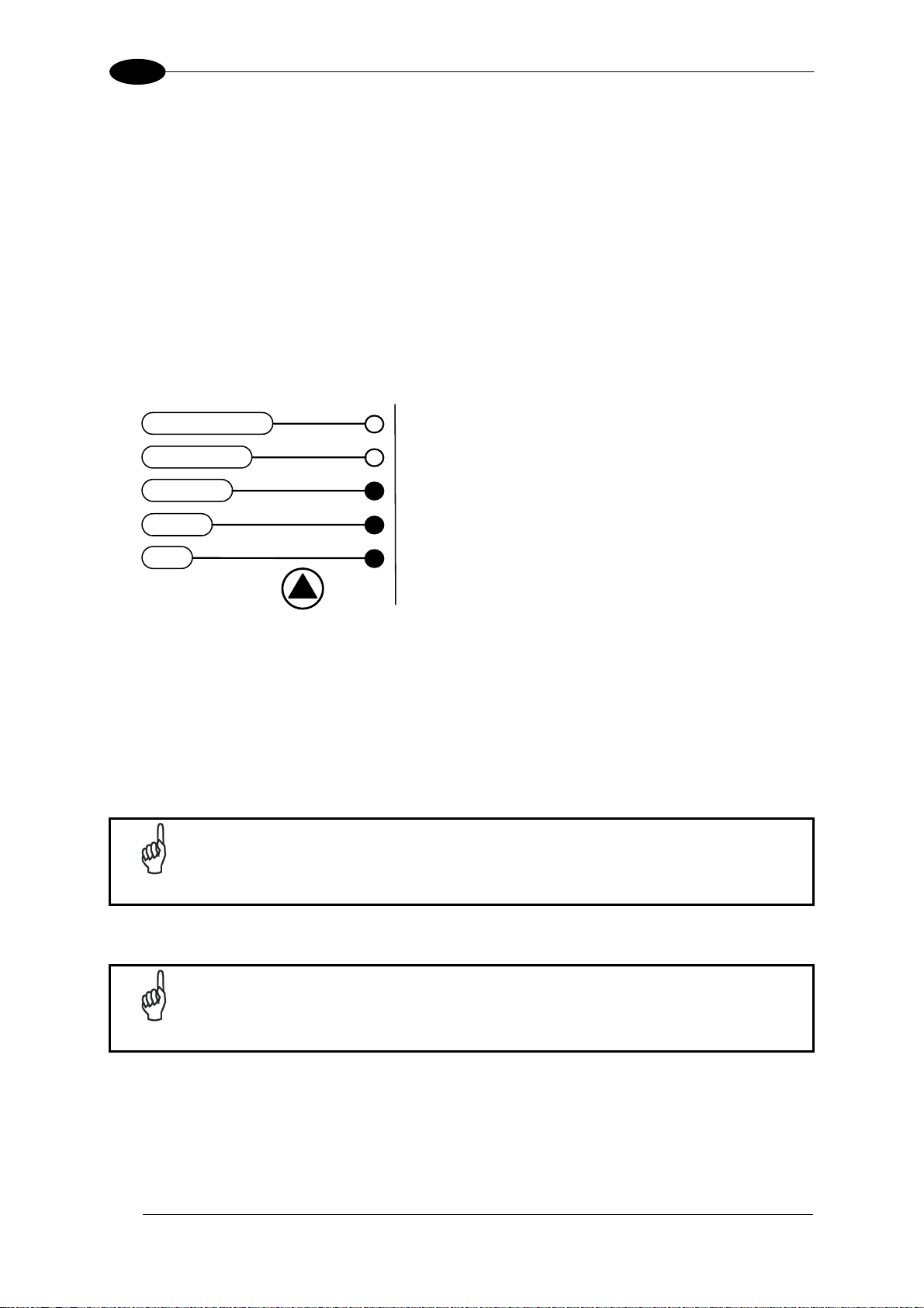
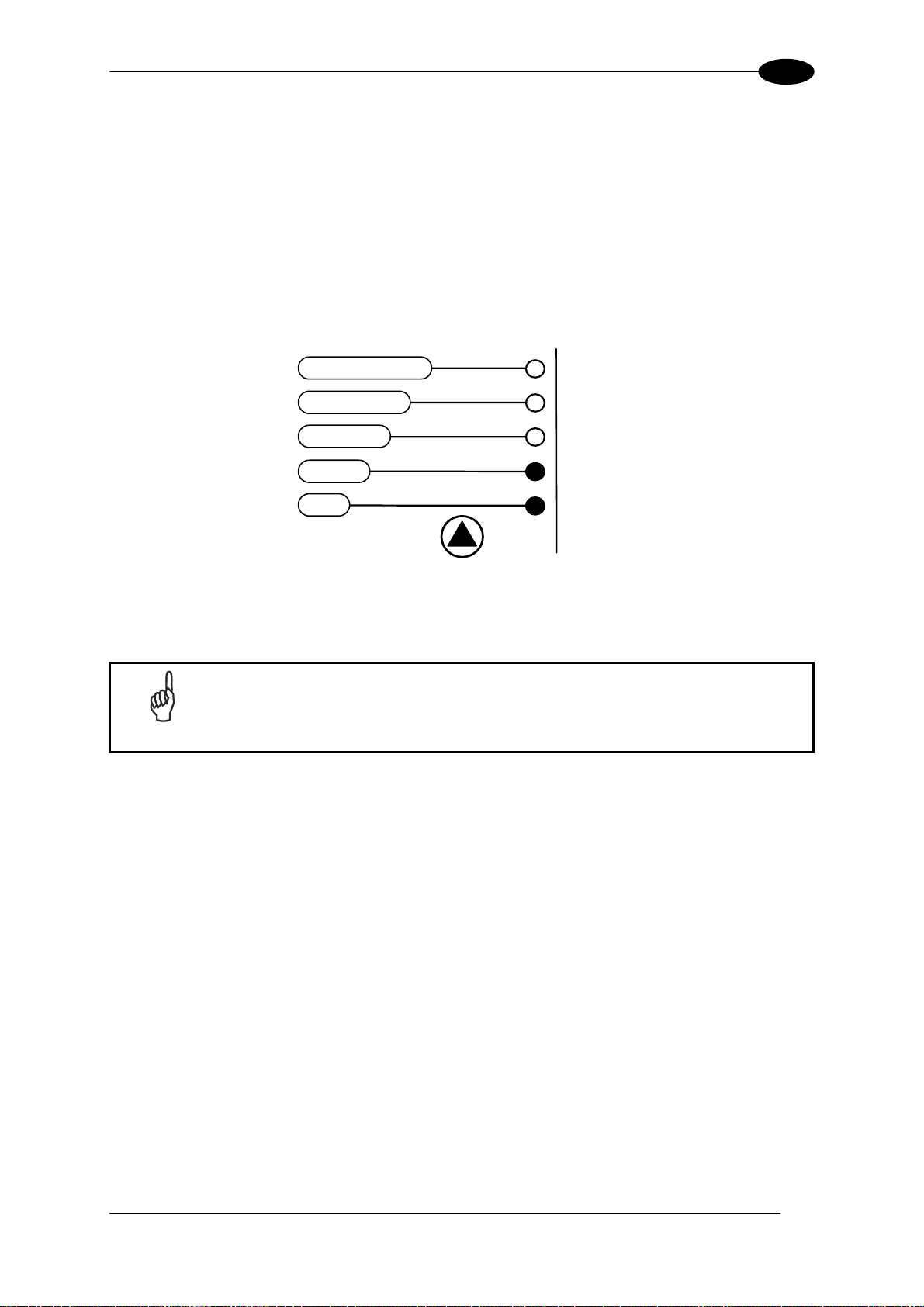
2.3.1 Diagnostic Indication
The “STATUS” and “READY” LEDs blink simultaneously to signal the presence of a failure.
Diagnostic message transmission on interfaces can be enabled to provide details about
specific failure conditions.
At the same time one or more LEDs light up according to the following scheme:
LED STATUS
READY BLINK
GOOD
TRIGGER ON to indicate a Motor Failure.
COM ON to indicate a Laser Failure.
STATUS BLINK
ON to indicate any Failure different than
Motor or Laser failures.
SETUP
LEARN
TES
READ
GOOD
TRIGGER
COM
STATUS
19
Page 30
2
T
Y
T
T
T
T
T
DS2100N REFERENCE MANUAL
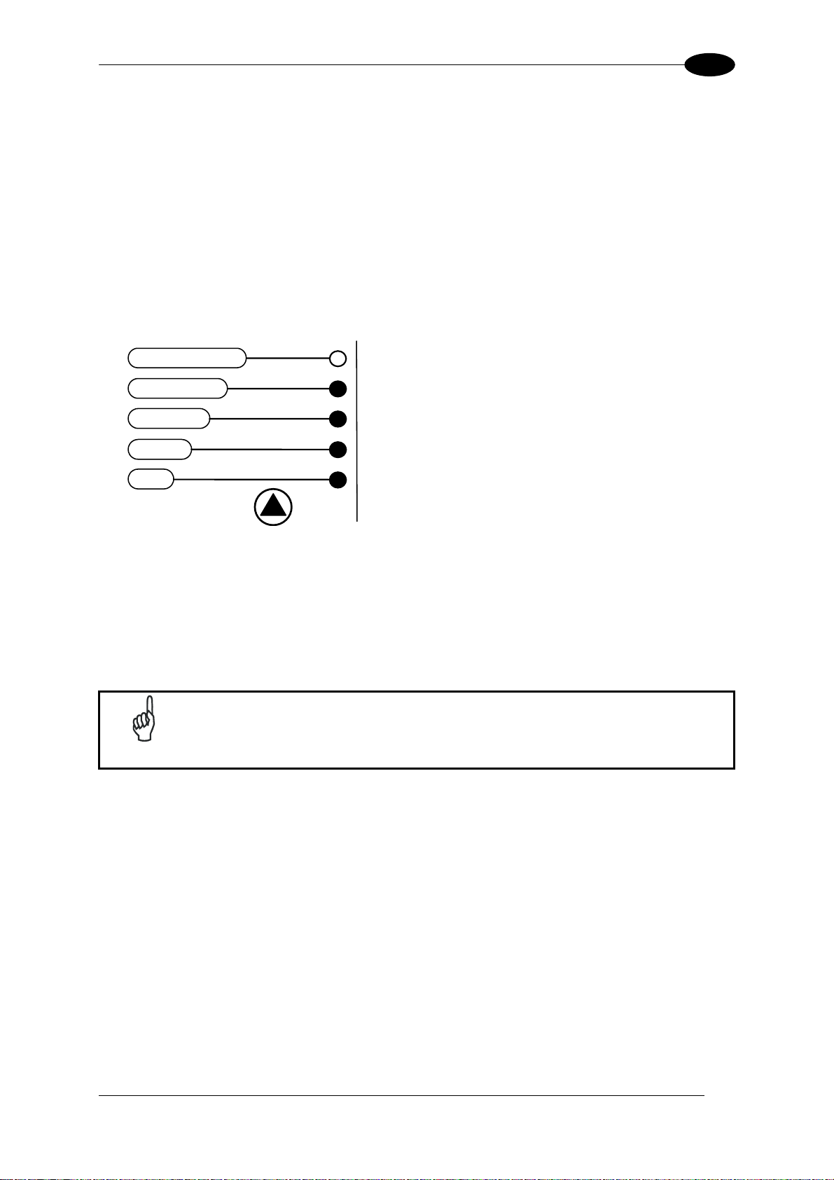
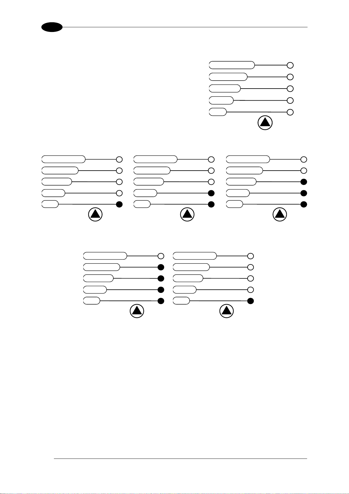
2.3.2 X-PRESS™ Functions
Quick access to the following functions is provided by
an easy procedure using the push button:
1 – Press the button (the STATUS LED will give a
visual feedback).
2 – Hold the button until the specific function LED is
on (TEST, LEARN or SETUP).
3 – Release the button to enter the specific function.
Once button is pressed, the cycle of LEDs activation is as follows:
READY
READY
SETUP
LEARN
TES
READ
GOOD
TRIGGER
COM
STATUS
READY
SETUP
LEARN
TES
Release button to
Exit
GOOD
TRIGGER
COM
STATUS
SETUP
LEARN
TES
Release button to
enter Test Mode
GOOD
TRIGGER
COM
STATUS
SETUP
LEARN
TES
Release button to
enter AutoLearn
GOOD
TRIGGER
COM
STATUS
SETUP
LEARN
TES
Release button to
enter AutoSetup
READY
GOOD
TRIGGER
COM
STATUS
SETUP
LEARN
TES
Release button to
Exit
READY
GOOD
TRIGGER
COM
STATUS
(cycle)
Test Mode Function
Once entered, the Bar-Graph on the five LEDs is activated and if the scanner starts reading
barcodes the Bar-Graph shows the Good Read Rate. In case of no read condition, only the
STATUS LED is on and blinks.
To exit the Test Mode, press the X-PRESS™ push button once.
20
Page 31

INTRODUCTION
2
AutoLearn Function
Once entered, the reader starts a procedure to automatically detect and recognize barcodes
(by type and length), which are presented to it
1
. The laser turns on and the LEARN LED
blinks to indicate the ongoing process.
The procedure is as follows:
- place the desired barcode on the scanline.
- wait until the LEARN LED stays steady on (indicating the reader has detected the
barcode).
- repeat, if needed, the above two steps to program up to 10 different barcodes (the LEARN
LED returns to the blinking state for the next code). If more than one barcode is detected
in the scan line, the Multi Label mode is enabled (refer to the “2K/4K Family Software
Configuration Parameter Guide” Help file).
- exit the process by pressing the X-PRESS™ push button once.
The scanner will restart at the end of the process, and then the detected barcodes are
automatically configured in scanner memory.
AutoSetup Function
Once entered, if a barcode label is positioned in front of the scanline, the scanner
automatically performs the optimal setup of the reading parameters for that specific barcode.
The procedure is as follows:
- place the desired barcode on the scanline.
- enter the AutoSetup function (the laser turns on and the SETUP LED blinks to indicate
the ongoing process).
- wait until the SETUP LED stays steady on (indicating the reader has detected the
barcode).
This procedure ends either when the barcode is successfully decoded or after a timeout of
about 7 (seven) seconds.
The scanner will restart at the end of the process, and then the optimized reading
parameters for that barcode are automatically configured in scanner memory.
The AutoSetup function does not modify the programmed barcode
NOTE
symbologies. If needed, the AutoLearn function can be performed after
Autosetup.
1
In case of Programming Barcodes (refer to the “ID-NET™: Programming Barcodes And Setup Procedure”
document in the product CD)
21
Page 32
2
DS2100N REFERENCE MANUAL
Reset Scanner to Factory Default
If it ever becomes necessary to reset the scanner to the factory default values, you can
perform this procedure by holding the X-PRESS™ push button pressed while powering up
the scanner. At the end of the procedure (about 5-6 seconds), the Configuration and
Environmental parameters are reset, all LEDs blink simultaneously 3 times and the message
"Default Set" is shown on the display.
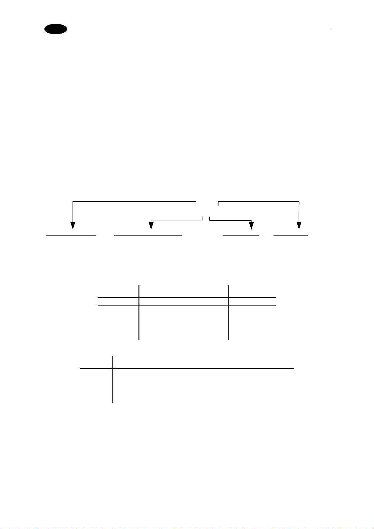
2.4 MODEL DESCRIPTION
The DS2100N scanner is available in versions that differ in regard to the following
parameters:
• Resolution
• Performance
• Linear or raster reading
Optical Resolution
1 = Standard resolution
2 = High resolution
Communication Interface
2= RS232/RS485main + RS232 aux
+ RS485 ID-NET™
DS2100N - X X X X
Optic Version
0 = Linear
1 = Raster R1
The following tables display each version’s reading performance.
Version Max Code Resolution Speed
mm (mils) scans/s
12X0 0.20 (8) 500 to 800
12X4 0.15 (6) 800 to 1000
22X0 0.15 (6) 500 to 800
22X4 0.12 (5) 800 to 1000
Version Reading Distance
12X0 40 mm (1.6 in) - 300 mm (11.8 in) on 0.50mm (20 mils) codes
12X4 50 mm (1.8 in) - 310 mm (11.8 in) on 0.50 mm (20 mils) codes
22X0 30 mm (1.2 in) - 90 mm (3.5 in) on 0.30 mm (12 mils) codes
2XX4 45 mm (1.8) – 100 mm (3.9 in) on 0.20 mm (8 mils) codes
See reading diagrams in par. 7.4 for further details.
Performance
0 = Standard
4 = High Performance
22
Page 33

INTRODUCTION
2
2.5 ACCESSORIES
The following accessories are available on request for the DS2100N:
Name
GFC-200 Contact Reading Mirror 93A201106
GFC-2000 105° Reading Mirror 93A201080
GFC-2100 90° Reading Mirror 93A201000
OM2000N Oscillating Mirror 93ACC1783
CBX100 Compact Connection Box 93A301067
CBX100LT Compact Connection Box Low Temp 93A301069
CBX500 Modular Connection Box 93A301068
BM100 Backup Module 93ACC1808
BM150 Display Module 93ACC1809
* BM300/310 Profibus Module STD/IP65 93ACC1810, 93ACC1811
* BM400 DeviceNet Module IP65 93ACC1814
* BM500/510/520 Ethernet/IP Module STD/IP65/IP54 93ACC1812, 93ACC1813,
* BM600 CANopen Module STD 93ACC1815
* BM700 Profinet Module STD 93ACC1816
* BM1100 CC-Link Module STD 93ACC1845
* BM1200/1210 Modbus TCP 93ACC1848, 93ACC1849
BA100 DIN Rail Adapters 93ACC1821
BA200 Bosch Adapters 93ACC1822
PH-1 Photocell Kit PNP 93ACC1791
MEP-543 Photocell Kit NPN 93ACC1728
PG-6000/6001/6002 24 V Power Supply Unit EU/UK/US 93ACC1720, 93ACC1719,
* Fieldbus Module accessories are compatible with Standard Application Package 2K4K Rel.003 or later.
Description Part Number
93ACC1840
93ACC1718
23
Page 34
3
DS2100N REFERENCE MANUAL
3 INSTALLATION
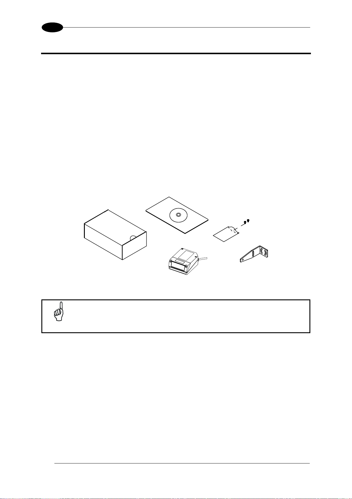
3.1 PACKAGE CONTENTS
Verify that the DS2100N reader and all the parts supplied with the equipment are present
and intact when opening the packaging; the list of parts includes:
• DS2100N reader with cable
• DS2100N Quick Guide
• Barcode Test Chart
• Genius™ CD-ROM
• Replicate serial number labels
• Mounting Kit: - bracket
- screws
NOTE
Figure 11- DS2100N Package Contents
The replicate serial number labels are for external reference and can be
applied to the reading station and/or to the OM2000N accessory when used.
24
Page 35
INSTALLATION
3
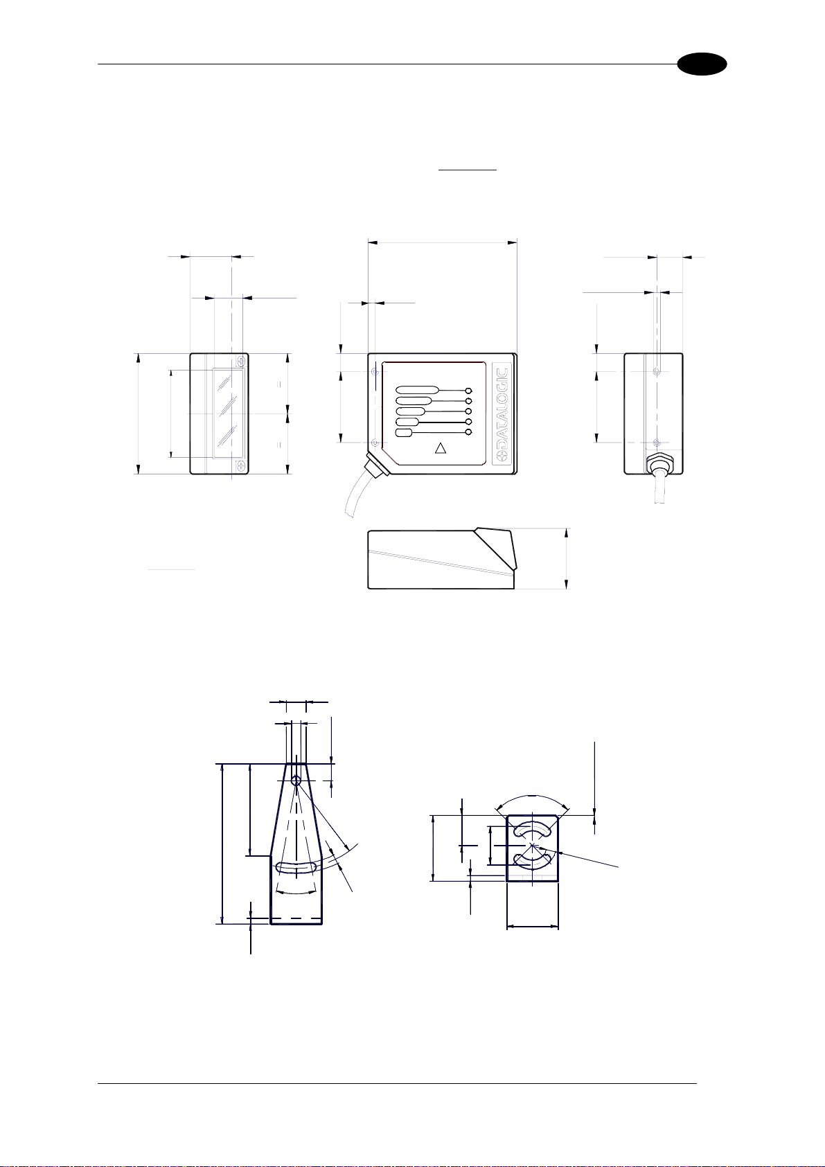
3.2 MECHANICAL INSTALLATION
DS2100N can be installed to operate in different positions. The four screw holes (M4 x 5) on
the body of the reader are for mechanical fixture (
overall dimensions of the scanner and mounting bracket and may be used for installation.
Refer to par. 3.2.1 and 3.3 for correct positioning.
23.3*
0.92
14
68
46
2.68
0.55
10.3
40
1.81
0.16
0.41
1.57
Figure A, 3). The diagrams below give the
84
3.31
14.7
0.58
4
X
F2
F1
F0
PRESS
INTERFACE
DS2100N
READY
F4
GOOD
F3
TRIGGER
COM
STATUS
M 4 n° 4
0.41
10.3
40
1.57
mm
inch
* The quote refers to the scan line
42
73
2.5
Figure 13 – Mounting Bracket Overall Dimensions
Figure 12 – DS2100N Overall Dimensions
9
4.2
7.8
R
4
0
13.8
20°
30
4
.
2
mm
17.5
2.5
90°
23
32.7
4
1.29
1 x 45° n° 2
.
2
n
°
2
25
Page 36
3
DS2100N REFERENCE MANUAL
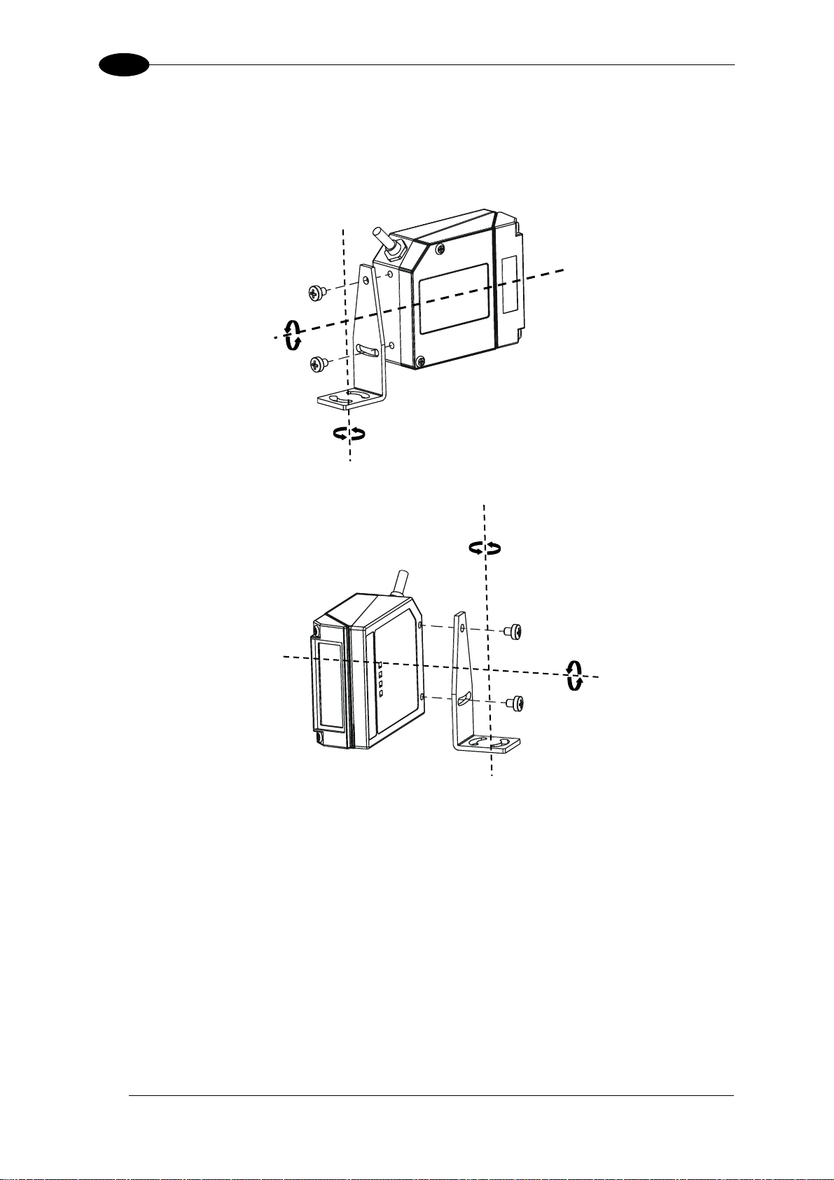
3.2.1 Mounting DS2100N
Using the DS2100N mounting bracket you can obtain the most suitable position for the
reader as shown in the figure below:
Tilt
Skew
Skew
Pitch
Figure 14 – Positioning with Mounting Bracket
26
Page 37
INSTALLATION
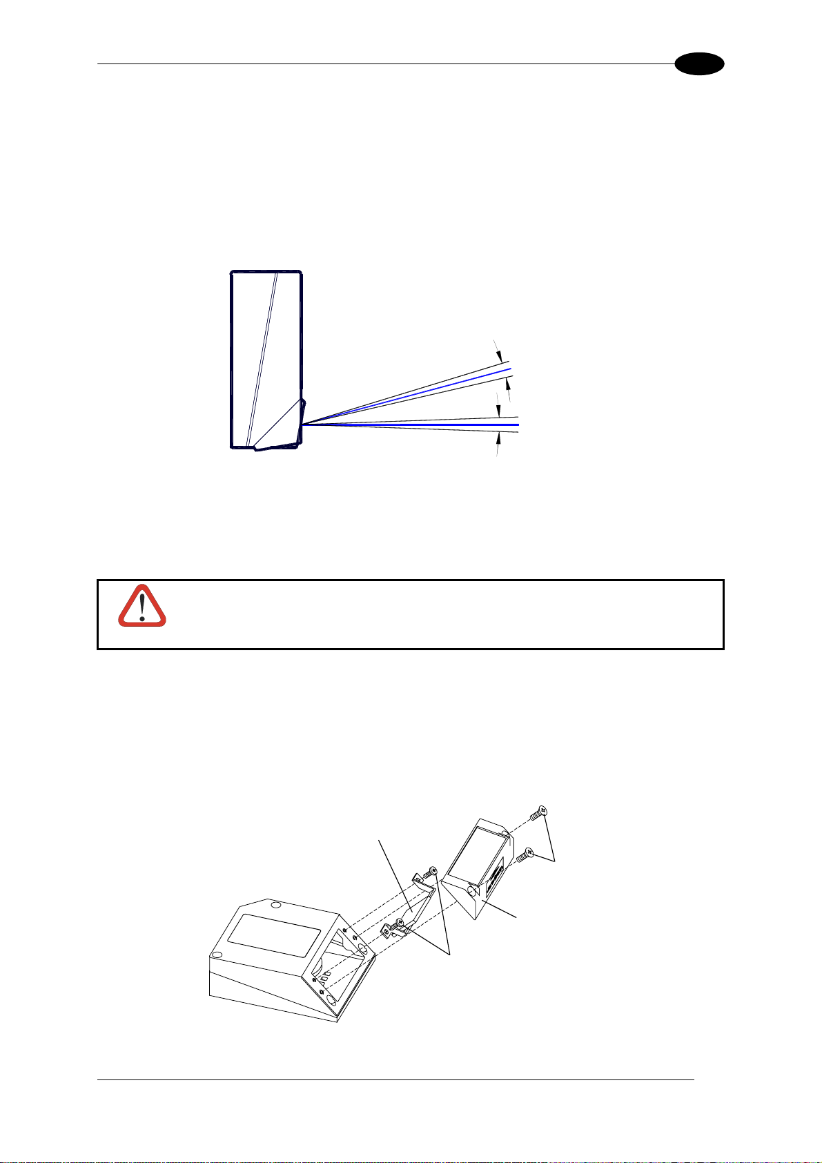
3.2.2 Mounting Scanner Accessories
GFC-2X00s are accessory deflection mirrors available on request for DS2100N.
• The GFC-2000 is a 75° deflection mirror
• The GFC-2100 is a 90° deflection mirror
The reading position with respect to the scanner is shown below for each mirror.
3
GFC-2000
75° ± 2°
Laser Beam
90° ± 2°
GFC-2100
Figure 15 - GFC-2X00 Laser Beam Output Position
The installation of the deflection mirror is very easy (Figure 16).
Avoid any contact with the deflection mirror, mirrored rotor, the lenses or
other optical components; otherwise the performance of the reader will be
CAUTION
1. Turn off the device.
2. Remove the DS2100N scanning window unscrewing the two cover screws.
3. Fix the mirror to the device by means of the two fixing screws.
reduced.
4. Remount the scanning window so that the opening face is now at 90° with respect to the
DS2100N body.
deflection mirror
Cover screws
Scanning window
Fixing screws
Figure 16 - Installation of the Deflection Mirror
27
Page 38
3
DS2100N REFERENCE MANUAL
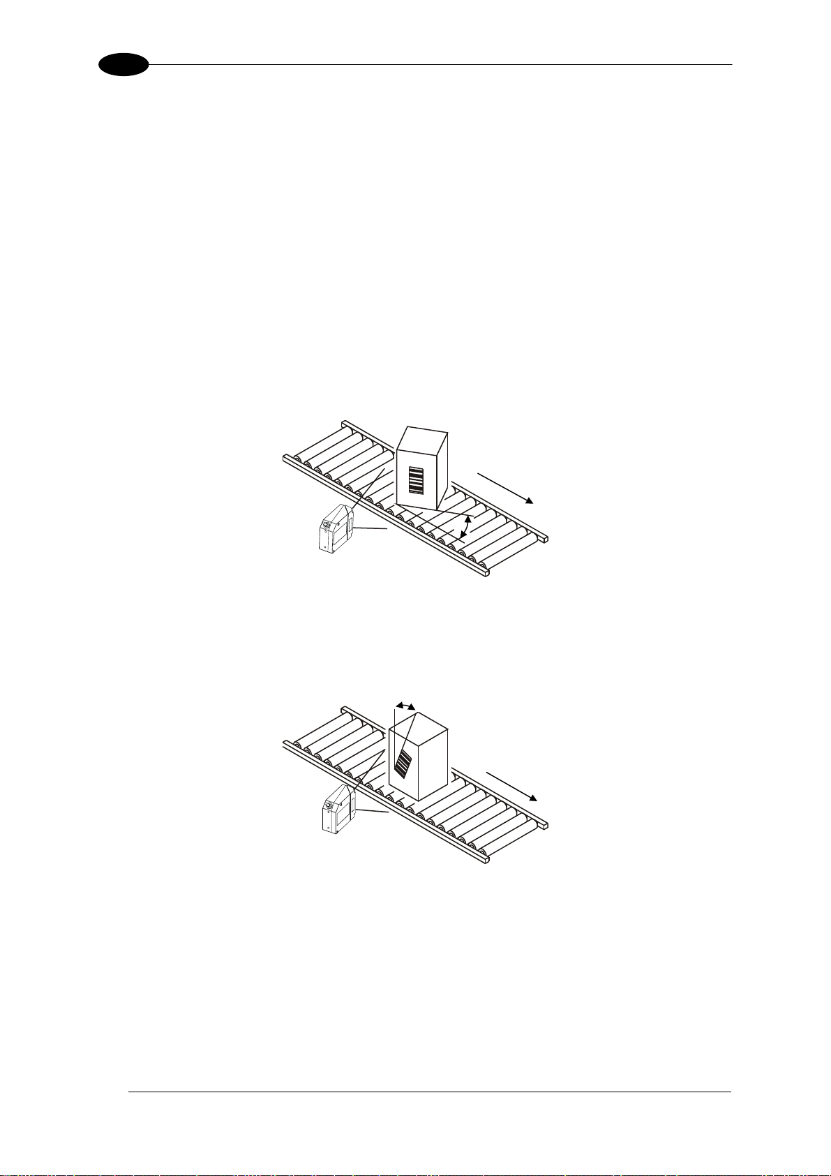
3.3 POSITIONING
The DS2100N scanner is able to decode moving barcode labels at a variety of angles,
however significant angular distortion may degrade reading performance.
When mounting the DS2100N take into consideration these three ideal label position angles:
Skew 10° to 30°, Tilt 0° and Pitch 0°.
Follow the suggestions for the best orientation:
The Skew angle is represented by the value S in Figure 17. Position the reader to assure at
least 10° for the Skew angle. This avoids the direct reflection of the laser light emitted by the
DS2100N.
For the raster version, this angle refers to the most inclined or external raster line, so that all
other raster lines assure more than 10° Skew.
S
Figure 17 - Skew Angle
The Tilt angle is represented by the value T in Figure 18. Position the reader in order to
minimize the Tilt angle.
T
Figure 18 - Tilt Angle
By using the ACB (Advanced Code Builder) software parameter, the tilt angle is less critical
and can be decoded even if the scan line doesn’t cross the entire code.
See par. 7.1 or the Help On Line for details.
28
Page 39

INSTALLATION
3
The Pitch angle is represented by the value P in Figure 19. Position the reader in order to
minimize the Pitch angle.
P
Figure 19 - Pitch Angle
29
Page 40
4
DS2100N REFERENCE MANUAL
4 CBX ELECTRICAL CONNECTIONS
All DS2100N models are equipped with a cable terminated by a 25-pin male D-sub connector
for connection to the power supply and input/output signals.
We recommend making system connections through one of the CBX connection boxes since
they offer the advantages of easy connection, easy device replacement and filtered
reference signals.
If you require direct wiring to the scanner the details of the connector pins
NOTE
The table below gives the pinout of the CBX100/500 terminal block connectors. Use this
pinout when the DS2100N reader is connected by means of the CBX100/500:
Vdc Power Supply Input Voltage +
GND Power Supply Input Voltage -
Earth Protection Earth Ground
+V Power Source – External Trigger
I1A External Trigger A (polarity insensitive)
I1B External Trigger B (polarity insensitive)
-V Power Reference – External Trigger
+V Power Source – Inputs
I2A Input 2 A (polarity insensitive)
I2B Input 2 B (polarity insensitive)
-V Power Reference – Inputs
+V Power Source - Outputs
-V Power Reference - Outputs
O1+ Output 1 +
O1- Output 1 -
O2+ Output 2 +
O2- Output 2 -
TX Auxiliary Interface TX
RX Auxiliary Interface RX
SGND Auxiliary Interface Reference
REF Network Reference
ID+ ID-NET™ network +
ID- ID-NET™ network -
Shield Network Cable Shield
RS232
TX TX+ RTX+
RX
RTS TX- RTX CTS
SGND SGND SGND
and relative connections are indicated in Chaper 5.
CBX100/500 Terminal Block Connectors
Input Power
Inputs
Outputs
Auxiliary Interface
ID-NET™
Main Interface
RS485
Full-Duplex
*RX+
*RX-
RS485
Half-Duplex
* Do not leave floating, see par. 4.2.2 for connection details.
30
Page 41
CBX ELECTRICAL CONNECTIONS
4
To avoid electromagnetic interference when the scanner is connected to a
NOTE
CBX connection box, verify the jumper positions in the CBX as indicated in
its Installation Manual.
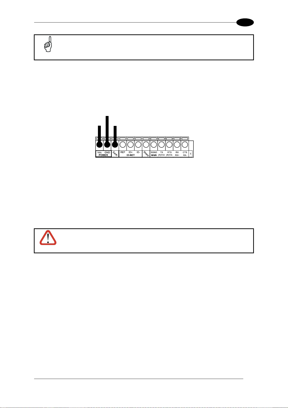
4.1 POWER SUPPLY
Power can be supplied to the scanner through the CBX100/500 spring clamp terminal pins
as shown in Figure 20:
Power Supply
VGND
V+
Earth
Ground
in
Figure 20 - Power Supply Connections
The power must be between 10 and 30 Vdc only.
It is recommended to connect the device CHASSIS to earth ground (Earth) by setting the
appropriate jumper in the CBX connection box. See the CBX Installation Manual for details.
4.2 MAIN SERIAL INTERFACE
Do not connect to the Main Interface spring clamp terminals if using Host
Interface Modules (Fieldbus) with the CBX500.
CAUTION
The signals relative to the following serial interface types are available on the CBX spring
clamp terminal blocks.
If the interface type is not compatible with the current communication handshaking, then the
system forces the handshake to none.
The main interface type and the relative parameters (baud rate, data bits, etc.) can be
set using the Genius™ utility program or the Genius™ based Host Mode Programming
procedure.
Details regarding the connections and use of the interfaces are given in the next paragraphs.
31
Page 42

4
DS2100N REFERENCE MANUAL
4.2.1 RS232 Interface
The serial interface is used in this case for point-to-point connections; it handles
communication with the host computer and allows both transmission of code data and the
programming of the scanner. This is the default setting.
The following pins are used for RS232 interface connection:
CBX100/500
TX Transmit Data
RX Receive Data
RTS Request To Send
CTS Clear To Send
SGND Signal Ground
It is always advisable to use shielded cables. The overall maximum cable length must be
less than 15 m (49.2 ft).
Function
USER INTERFACE
SGND RXD TXD
CTS RTS
SCANNER
Figure 21 – RS232 Main Interface Connections Using Hardware Handshaking
SGND TX RX
RTS CTS
The RTS and CTS signals control data transmission and synchronize the connected devices.
+ V
RTS
- V
+ V
TX DATA
- V
START
OF
TRANSMISSION
TRANSMISSION
C1
DATA
C2
TRANSMISSION
STOPPED
DATA
TRANSMISSION
C4
C3
END
OF
TRANSMISSION
C5
+ V
CTS
- V
IDLE
ENABLED
DISABLED
Figure 22 - RS232 Control Signals
ENABLED
IDLE
If the RTS/CTS handshaking protocol is enabled, the DS2100N activates the RTS output to
indicate a message is to be transmitted. The receiving unit activates the CTS input to enable
the transmission.
32
Page 43

CBX ELECTRICAL CONNECTIONS
4
4.2.2 RS485 Full-Duplex Interface
The RS485 full-duplex (5 wires + shield) interface is used for non-polled communication
protocols in point-to-point connections over longer distances (max 1200 m / 3940 ft) than
those acceptable for RS232 communications or in electrically noisy environments.
The CBX pinout follows:
CBX100/500
TX+ RS485 Transmit Data +
RX+ RS485 Receive Data +
TX- RS485 Transmit Data -
RX- RS485 Receive Data -
SGND Signal Ground
Function
USER INTERFACE
RX485+ TX485+
SGND RX485- TX485-
SCANNER
Figure 23 - RS485 Full-duplex Connections
SGND TX+ RX+
TX- RX-
For applications that do not use RX485 signals, do not leave these lines
NOTE
floating but connect them to SGND as shown below.
SCANNER
Figure 24 - RS485 Full-duplex Connections using Only TX Signals
USER INTERFACE
RX485+
SGND RX485-
SGND TX+
TX-
33
Page 44

4
DS2100N REFERENCE MANUAL
4.2.3 RS485 Half-Duplex Interface
This interface is provided for backward compatibility. We recommend using
NOTE
The RS485 half-duplex (3 wires + shield) interface is used for polled communication
protocols.
It can be used for Multidrop connections with a Datalogic Multiplexer, (see par. 6.5) exploiting
a proprietary protocol based on polled mode called MUX32 protocol, where a master device
polls slave devices to collect data.
the more efficient ID-NET™ network for Master/Slave or Multiplexer layouts.
CBX100/500
Function
RTX+ RS485 Receive/Transmit Data +
RTX- RS485 Receive/Transmit Data -
SGND Signal Ground
USER INTERFACE
RTX485+
SGND RTX485-
SCANNER
Figure 25 - RS485 Half-duplex Connections
SGND RTX+
RTX-
This interface is forced by software when the protocol selected is MUX32 protocol.
In a Multiplexer layout, the Multidrop address must also be set via serial channel by the
Genius™ utility or by the Host Programming Mode.
Figure 26 shows a multidrop configuration with DS2100N scanners connected to a
Multiplexer.
This is an example of multidrop wiring. Consult the multiplexer manual for
complete wiring instructions.
CAUTION
34
Page 45

CBX ELECTRICAL CONNECTIONS
4
Figure 26 - DS2100N Multidrop Connection to a Multiplexer
35
Page 46

4
DS2100N REFERENCE MANUAL
4.3 ID-NET™ INTERFACE
CBX100/500 Function
Shield Network Cable Shield
ID+ ID-NET™ network +
ID- ID-NET™ network -
REF Network Reference
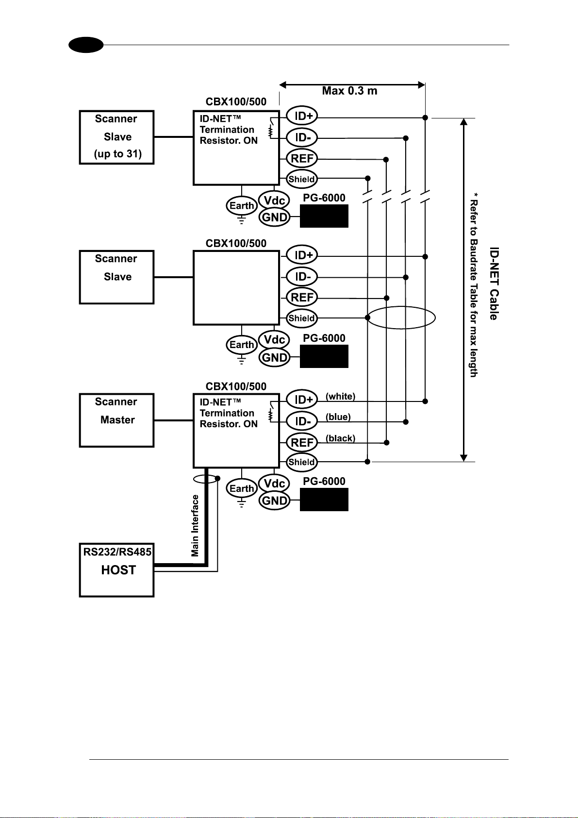
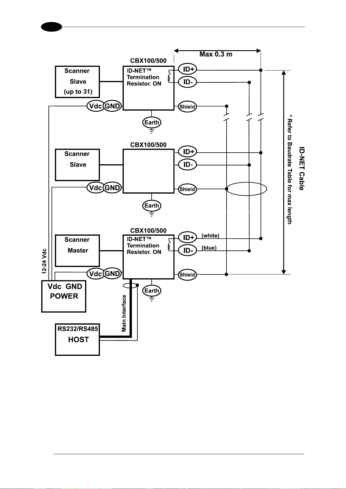
4.3.1 ID-NET™ Cables
The following instructions are referred to Figure 28, Figure 29 and Figure 30.
• The general cable type specifications are: CAT5 twisted pair + additional CAT5 twisted
pair, shielded cable AWG 24 (or AWG 22) stranded flexible.
We recommend using DeviceNet cables (drop or trunk type) to the following reference
standards:
AN50325 – IEC 62026
UL STYLE 2502 80°C 30V
• Cable Shield MUST be connected to earth ground ONLY at the Master.
• NEVER use ID-NET™ cable shield as common reference.
• The ID-NET™ max cable length depends on the baudrate used, (see the Baudrate Table
below).
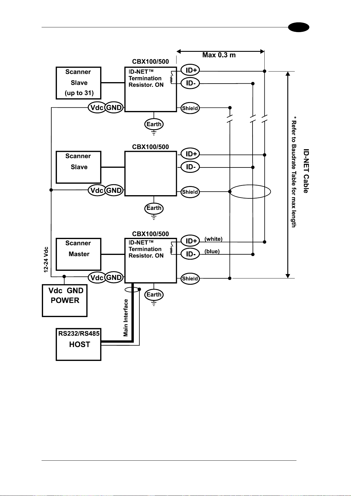
• For Common Power Connections use only 2 wires (ID+ and ID-).
- DC Voltage Power cable (Vdc – GND) should be handled as a signal cable (i.e. do not
put it together with AC cable):
- Wire dimensioning must be checked in order to avoid voltage drops greater than 0.8
Volts.
- Cable should lie down as near as possible to the ID-NET™ cable (avoiding wide loops
between them).
• Scanner's chassis may be connected to earth.
• Network inside the same building.
Baudrate Table
Baud Rate 125 kbps 250 kbps
Cable Length 1200 m 900 m
500 kbps
700 m
1Mbps
*
* Application dependent, contact your Datalogic Automation representative for details.
36
NOTE
The default ID-NET™ baudrate is 500 kbps. Lower ID-NET™ baudrates
allow longer cable lengths. The baudrate is software configurable by
authorized Datalogic Automation personnel only.
Page 47

CBX ELECTRICAL CONNECTIONS
4
4.3.2 ID-NET™ Response Time
The following figure shows the response time of the ID-NET™ network. This time is defined
as the period between the Trigger activation and the beginning of data transmission to the
Host.
Max ID-NET™ Response Time
240
220
200
180
160
140
120
100
80
Response Time (ms)
60
40
20
0
0 1 2 3 4 5 6 7 8 9 10 11 12 13 14 15 16
500 kbps 250 kbps
Figure 27 – ID-NET™ Response Time
CONDITIONS:
• ID-NET™ M/S Synchronized layout
• message length = 50 bytes per node
Number of Nodes
125 kbps
37
Page 48
4
DS2100N REFERENCE MANUAL
38
Figure 28 – ID-NET™ Network Connections with isolated power blocks
Page 49
CBX ELECTRICAL CONNECTIONS
4
Figure 29 - ID-NET™ Network Connections with Common Power Branch Network
39
Page 50
4
DS2100N REFERENCE MANUAL
40
Figure 30 – ID-NET™ Network Connections with Common Power Star Network
Page 51
CBX ELECTRICAL CONNECTIONS
4
4.3.3 ID-NET™ Network Termination
The network must be properly terminated in the first and last scanner of the network. This is
done by setting the ID-NET™ Termination Resistance Switch in the CBX100/500 to ON.
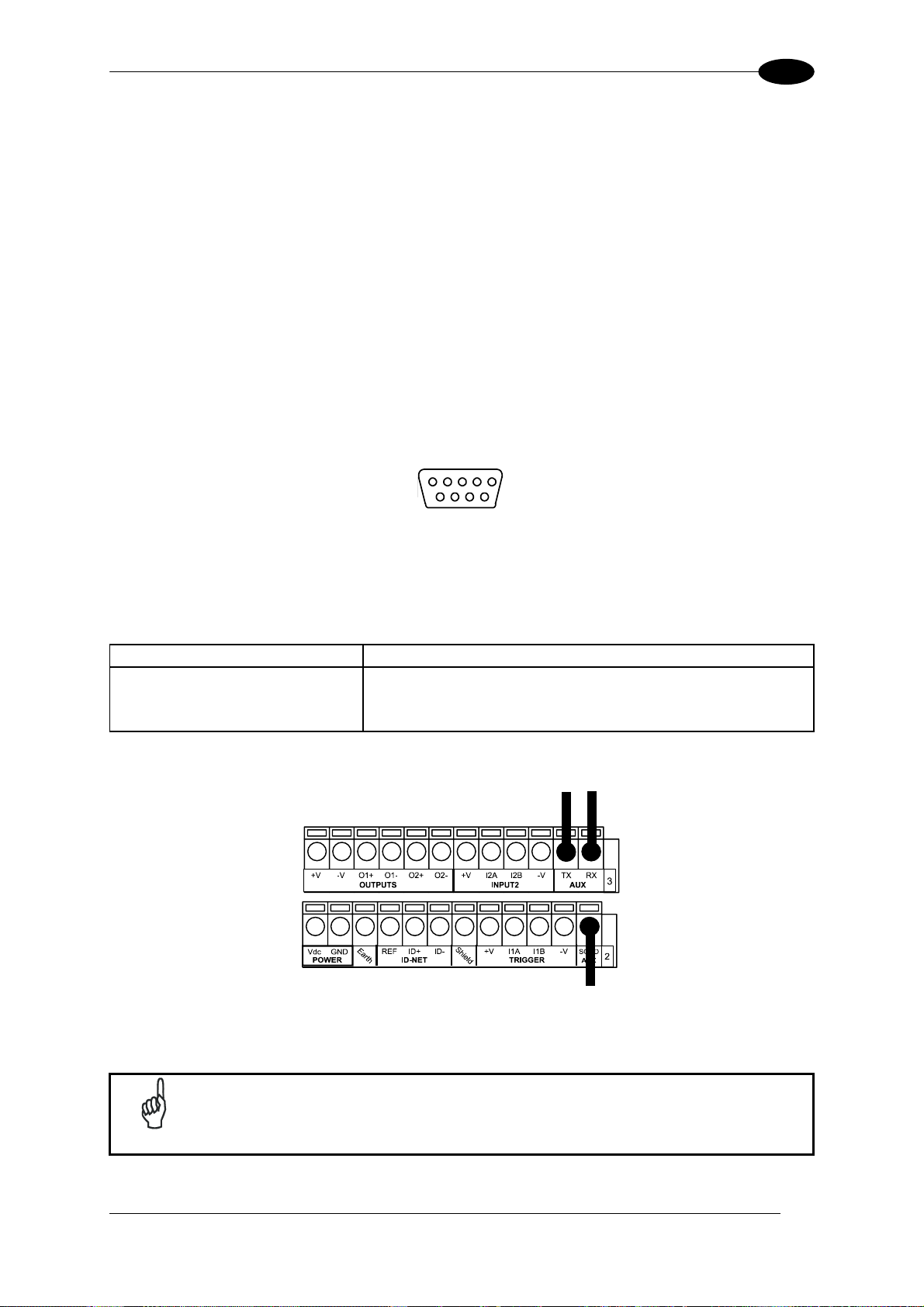
4.4 AUXILIARY RS232 INTERFACE
The auxiliary serial interface is used exclusively for RS232 point-to-point connections.
The parameters relative to the aux interface (baud rate, data bits, etc.) as well as particular
communication modes such as LOCAL ECHO can be defined using the Genius™ utility
program or Genius™ based Host Mode Programming installed from the CD-ROM.
The 9-pin female Auxiliary Interface connector inside the CBX is the preferred connector for
device configuration or communication monitoring.
5
1
69
Figure 31 - 9-pin female connector
If permanent system wiring is required, the following pins are used to connect the RS232
auxiliary interface:
CBX100/500 Function
RX Auxiliary Interface Receive Data
TX Auxiliary Interface Transmit Data
SGND Auxiliary Interface Reference
USER INTERFACE
RX TX
Reference
Figure 32 - RS232 Auxiliary Interface Connections
Do not connect the Aux Interface to the CBX spring clamp connectors and
NOTE
the 9-pin connector simultaneously.
41
Page 52
4
DS2100N REFERENCE MANUAL
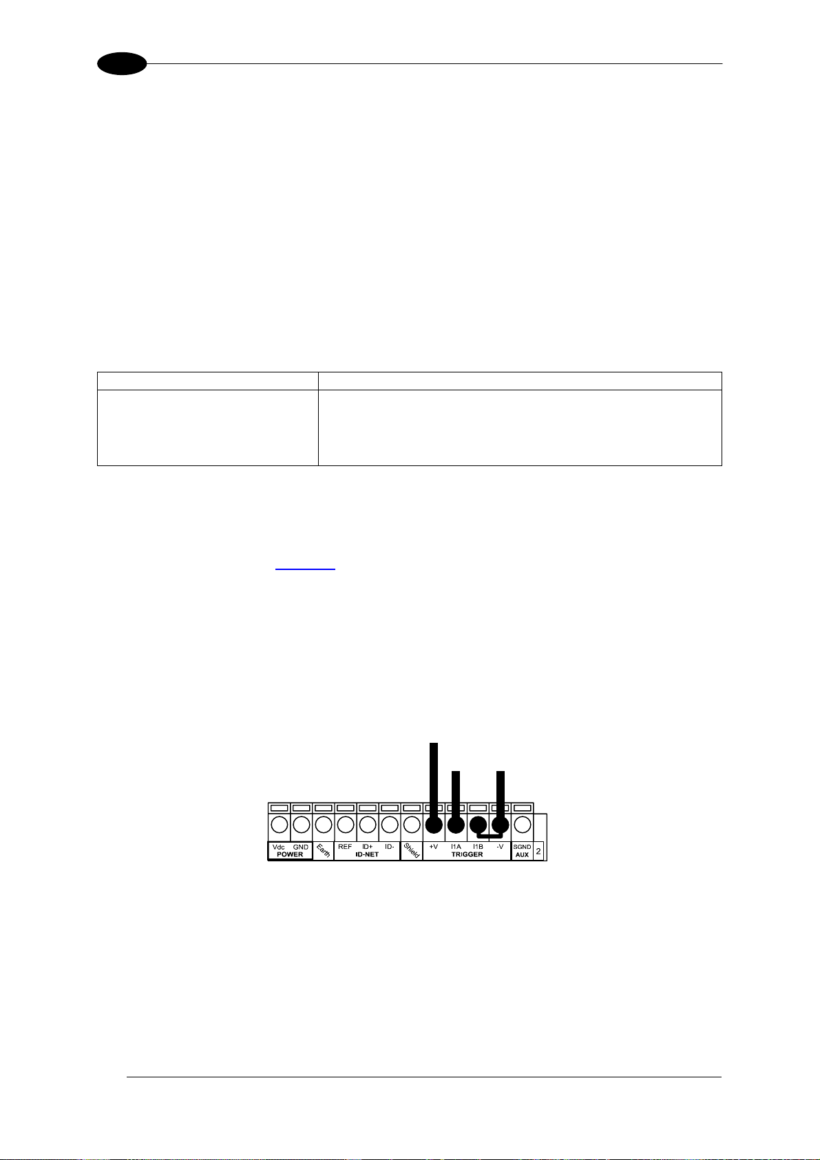
4.5 INPUTS
There are two optocoupled polarity insensitive inputs available on the scanner: Input 1
(External Trigger) and Input 2, a generic input:
The electrical features of both inputs are:
Maximum voltage: 30 Vdc
Maximum current: 12 mA (scanner) + 12 mA (CBX)
An anti-disturbance filter is implemented in software on both inputs so that the minimum
pulse duration is ≅ 5 milliseconds. This value can be increased through the software
parameter Debounce Filter, see the "2K/4K Family Software Configuration Parameter Guide”
Help file".
CBX100/500
+V Power Source - External Trigger
I1A External Trigger A (polarity insensitive)
I1B External Trigger B (polarity insensitive)
-V Power Reference - External Trigger
The External Trigger input is used in the On-Line operating Mode and tells the scanner to
scan for a code. The active state of this input is selected in software. Refer to the Genius™
Help On Line.
The yellow Trigger LED (
corresponds to ON.
This input is optocoupled and can be driven by both an NPN and PNP type command. The
connections are indicated in the following diagrams:
EXTERNAL TRIGGER INPUT CONNECTIONS USING DS2100N POWER
Function
Figure A, 3) is on when the active state of the External Trigger
PH-1 Photocell (PNP)
(brown)
42
(black) (blue)
Figure 33 – PH-1 (PNP) External Trigger Using DS2100N Power
Page 53

CBX ELECTRICAL CONNECTIONS
4
NPN Photocell
Power to Input
Photocell Signal
Photocell
Reference
Figure 34 - NPN External Trigger Using DS2100N Power
EXTERNAL TRIGGER INPUT CONNECTIONS USING EXTERNAL POWER
PNP Photocell
Input
Signal
Pulled down to External
Input Device Reference
Figure 35 - PNP External Trigger Using External Power
NPN Photocell
Pulled up to External
Input Device Power
Input
Signal
Figure 36 - NPN External Trigger Using External Power
43
Page 54
4
DS2100N REFERENCE MANUAL
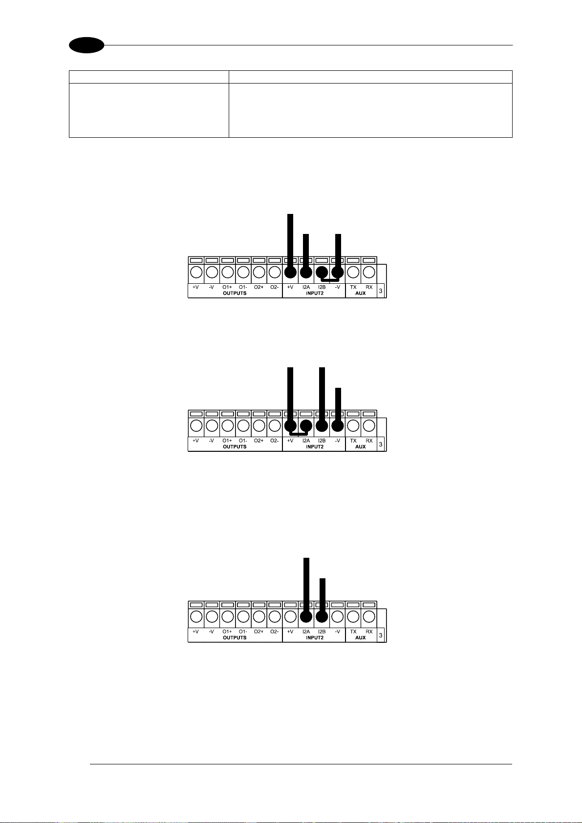
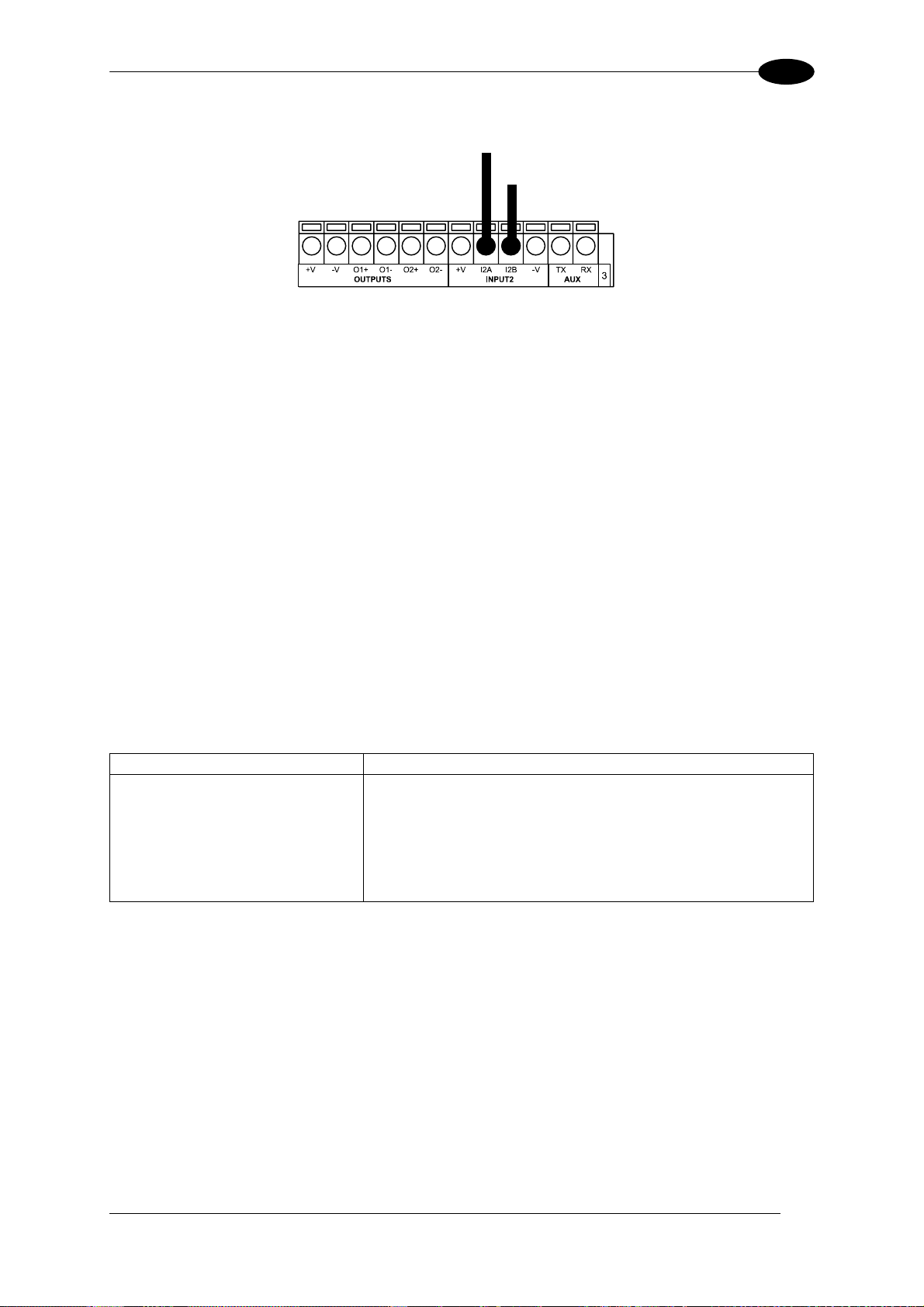
CBX100/500 Function
+V Power Source - Inputs
I2A Input 2 A (polarity insensitive)
I2B Input 2 B (polarity insensitive)
-V Power Reference - Inputs
INPUT 2 CONNECTIONS USING DS2100N POWER
Input Device
Power to
Input Device
Input Input Device
Signal Reference
PNP Input 2 Using DS2100N Power
Input Device
Power to Input
Input Device Signal
Input Device
Reference
NPN Input 2 Using DS2100N Power
INPUT 2 CONNECTIONS USING EXTERNAL POWER
Input Device
Input
Signal
Pulled down to External
Input Device Reference
Figure 37 - PNP Input 2 Using External Power
44
Page 55
CBX ELECTRICAL CONNECTIONS
4
Input Device
Pulled up to External
Input Device Power
Input
Signal
Figure 38 - NPN Input 2 Using External Power
4.5.1 Code Verifier
If the DS2100N is used as a Code Verifier, the verifier code can be configured in software
through the Genius™ configuration program. However it is also possible to use one of the
inputs to trigger when the scanner should store a code read as the verifier code.
The Code Verifier parameter must be enabled, and the configuration parameters to allow
correct Code Type reading must be saved to the scanner in order to read the verifier code.
When the selected input is activated, the next read code will be stored as the verifier code in
the scanner's non-volatile (Flash) memory.
For more details see the Verifier Parameters in the "2K/4K Family Software Configuration
Parameter Guide” Help file".
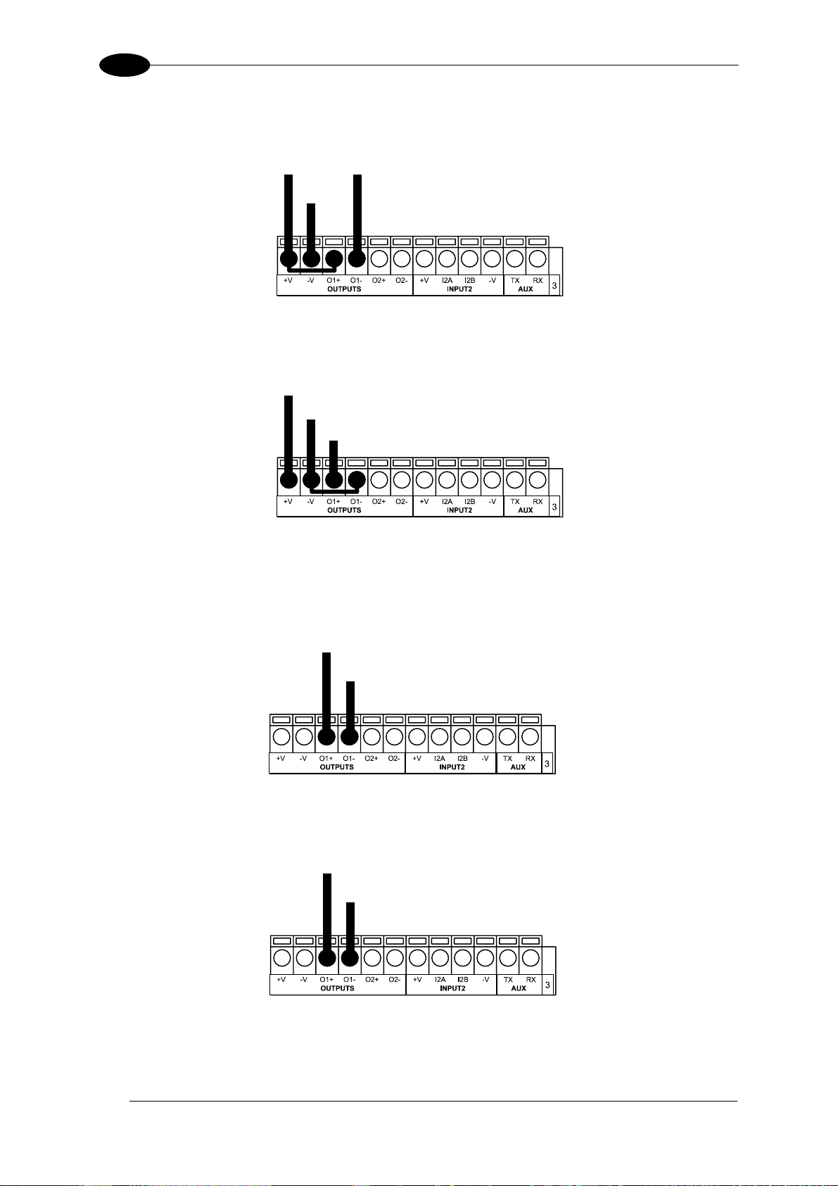
4.6 OUTPUTS
Two general purpose outputs are available.
CBX100/500
+V Power Source - Outputs
O1+ Output 1 +
O1- Output 1 -
O2+ Output 2 +
O2- Output 2 -
-V Power Reference Outputs
The meaning of the two outputs Output 1 and Output 2 can be defined by the user (No Read,
Right, Wrong, etc.). Refer to the Genius™ Help On Line.
By default, Output 1 is associated with the No Read event, which activates when the code
signaled by the external trigger is not decoded, and Output 2 is associated with the Complete
Read event, which activates when all the selected codes are correctly decoded.
The output signals are fully programmable being determined by the configured
Activation/Deactivation events, Deactivation Timeout or a combination of the two.
Function
45
Page 56
4
DS2100N REFERENCE MANUAL
OUTPUT CONNECTIONS USING DS2100N POWER
Output Device
Power to Output
Output device Signal
Output device
Reference
Figure 39 - Open Emitter Output Using DS2100N Power
Output Device
Power to
Output device
Output device
Reference
Output
Signal
Figure 40 - Open Collector Output Using DS2100N Power
OUTPUT CONNECTIONS USING EXTERNAL POWER
Output Device
Pulled up to External
Output Device Power
Output
Signal
Figure 41 - Open Emitter Output Using External Power
Output Device
Output
Signal
Pulled down to External
Output Device Reference
Figure 42 - Open Collector Output Using External Power
V
max = 30 Vdc
CE
I max = 40 mA continuous; 130 mA pulsed
46
Page 57
CBX ELECTRICAL CONNECTIONS
4
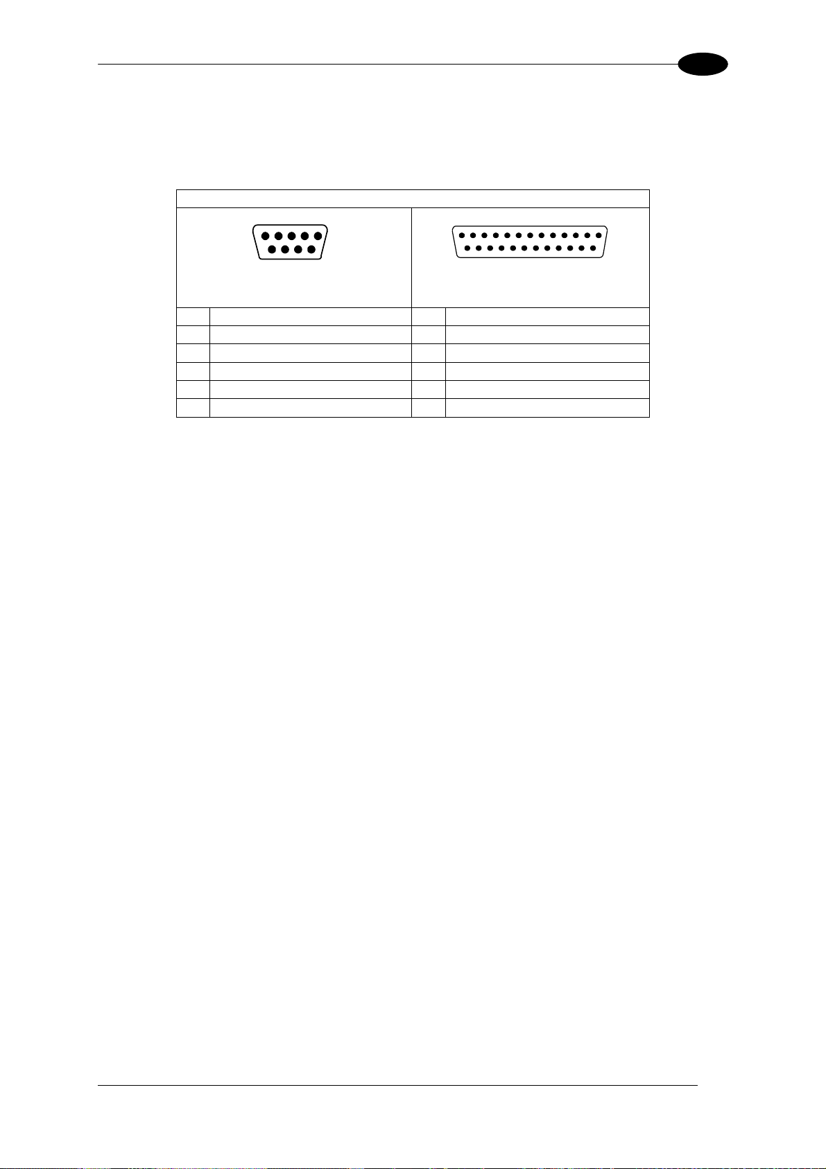
4.7 USER INTERFACE - HOST
The following table contains the pinout for standard RS232 PC Host interface. For other user
interface types please refer to their own manual.
RS232 PC-side connections
1
5
1
13
9 6
9-pin male connector
25-pin male connector
25 14
Pin Name Pin Name
2 RX 3 RX
3 TX 2 TX
5 GND 7 GND
7 RTS 4 RTS
8 CTS 5 CTS
47
Page 58

5
DS2100N REFERENCE MANUAL
5 25-PIN CABLE ELECTRICAL CONNECTIONS
All DS2100N models are equipped with a cable terminated by a 25-pin male D-sub connector
for connection to the power supply and input/output signals. The details of the connector pins
are indicated in the following table.
1
Figure 43 - 25-pin Male D-sub Connector
25-pin D-sub male connector pinout
Pin Name Function
13, 9 Vdc Power supply input voltage +
25, 7 GND Power supply input voltage -
1 CHASSIS Cable shield connected to chassis
18 I1A External Trigger A (polarity insensitive)
19 I1B External Trigger B (polarity insensitive)
6 I2A Input 2 A (polarity insensitive)
10 I2B Input 2 B (polarity insensitive)
8 O1+ Output 1 +
22 O1- Output 1 11 O2+ Output 2 +
12 O2- Output 2 20 RX Auxiliary Interface RX
21 TX Auxiliary Interface TX
23 ID+ ID-NET™ network +
24 ID- ID-NET™ network -
14, 15, 16, 17 NC Not Connected
Pin Name RS232
2 TX TX+ RTX+
3 RX *RX+
4 RTS TX- RTX-
5
MAIN INTERFACE
(SW SELECTABLE)
CTS *RX-
13
2514
RS485
Full-Duplex
RS485
Half-Duplex
* Do not leave floating, see par. 5.2.2 for connection details.
48
Page 59

25-PIN CABLE ELECTRICAL CONNECTIONS
5
5.1 POWER SUPPLY
Power can be supplied to the scanner through the pins provided on the 25-pin connector
used for communication with the host (Figure 44):
DS2100N
13
25
1
Vdc
GND
CHASSIS
POWER SUPPLY
V+ (10 - 30 Vdc)
VGND
CHASSIS
Earth Ground
Figure 44 - Power Supply Connections
The power must be between 10 and 30 Vdc only.
It is recommended to connect pin 1 (CHASSIS) to a common earth ground.
5.2 MAIN SERIAL INTERFACE
The signals relative to the following serial interface types are available on the input/output
connector of DS2100N.
If the interface type is not compatible with the current communication handshaking, then the
system forces the handshake to none.
The main interface type and the relative parameters (baud rate, data bits, etc.) can be
set using the Genius™ utility program or the Genius™ based Host Mode Programming
procedure.
Details regarding the connections and use of the interfaces are given in the next paragraphs.
49
Page 60

5
DS2100N REFERENCE MANUAL
5.2.1 RS232 Interface
The serial interface is used in this case for point-to-point connections; it handles
communication with the host computer and allows both transmission of code data and the
programming of the scanner. This is the default setting.
The following pins are used for RS232 interface connection:
25-pin
It is always advisable to use shielded cables. The overall maximum cable length must be
less than 15 m (49.2 ft).
Name Function
2 TX Transmit Data
3 RX Receive Data
4 RTS Request To Send
5 CTS Clear To Send
7 GND Ground
DS2100N
Chassis
TX
2
RX
3
RTS
4
CTS
5
7
GND
1
USER INTERFACE
RXD
TXD
CTS
RTS
GND
Figure 45 – RS232 Main Interface Connections Using Hardware Handshaking
The RTS and CTS signals control data transmission and synchronize the connected devices.
+ V
RTS
- V
+ V
TX DATA
- V
+ V
CTS
- V
START
OF
TRANSMISSION
ENABLED
IDLE
Figure 46 - RS232 Control Signals
DATA
TRANSMISSION
C2
C1
TRANSMISSION
STOPPED
DISABLED
DATA
TRANSMISSION
C4
C3
ENABLED
END
OF
TRANSMISSION
C5
IDLE
If the RTS/CTS handshaking protocol is enabled, the DS2100N activates the RTS output to
indicate a message is to be transmitted. The receiving unit activates the CTS input to enable
the transmission.
50
Page 61

25-PIN CABLE ELECTRICAL CONNECTIONS
5
5.2.2 RS485 Full-Duplex Interface
The RS485 full-duplex (5 wires + shield) interface is used for non-polled communication
protocols in point-to-point connections over longer distances (max 1200 m / 3940 ft) than
those acceptable for RS232 communications or in electrically noisy environments.
The connector pinout follows:
25-pin
Name Function
2 TX+ RS485 Transmit Data +
3 RX+ RS485 Receive Data +
4 TX- RS485 Transmit Data 5 RX- RS485 Receive Data 7 GND Ground
DS2100N
Chassis
2
TX+
4
TX-
3
RX+
RX-
5
7
GND
1
USER INTERFACE
+
RX485
-
+
TX485
-
GND
Figure 47 - RS485 Full-duplex Connections
For applications that do not use RX signals, do not leave these lines floating
NOTE
but connect them to GND as shown below.
DS2100N
Chassis
2
TX+
4
TX-
3
RX+
RX-
5
7
GND
1
USER INTERFACE
+
RX485
-
GND
Figure 48 - RS485 Full-duplex Connections using Only TX Signals
51
Page 62

5
DS2100N REFERENCE MANUAL
5.2.3 RS485 Half-Duplex Interface
This interface is provided for backward compatibility. We recommend using
NOTE
The RS485 half-duplex (3 wires + shield) interface is used for polled communication
protocols.
It can be used for Multidrop connections with a Datalogic Multiplexer, (see par. 6.5) exploiting
a proprietary protocol based on polled mode called MUX32 protocol, where a master device
polls slave devices to collect data.
The connector pinout follows:
25-pin
2 RTX+ RS485 Receive/Transmit Data +
4 RTX- RS485 Receive/Transmit Data 7 GND Ground
the more efficient ID-NET™ network for Master/Slave or Multiplexer layouts.
Name Function
DS2100N
MULTIPLEXER
2
Chassis
RTX+
4
RTX-
7
GND
1
RTX485 +
RTX485 -
RS485REF
Figure 49 - RS485 Half-duplex Connections
This interface is forced by software when the protocol selected is MUX32 protocol.
In a Multiplexer layout, the Multidrop address must also be set via serial channel by the
Genius™ utility or by the Host Programming Mode.
Figure 50 shows a multidrop configuration with DS2100N scanners connected to a
Multiplexer.
This is an example of multidrop wiring. Consult the multiplexer manual for
complete wiring instructions.
CAUTION
52
Page 63

25-PIN CABLE ELECTRICAL CONNECTIONS
5
Figure 50 - DS2100N Multidrop Connection to a Multiplexer
53
Page 64
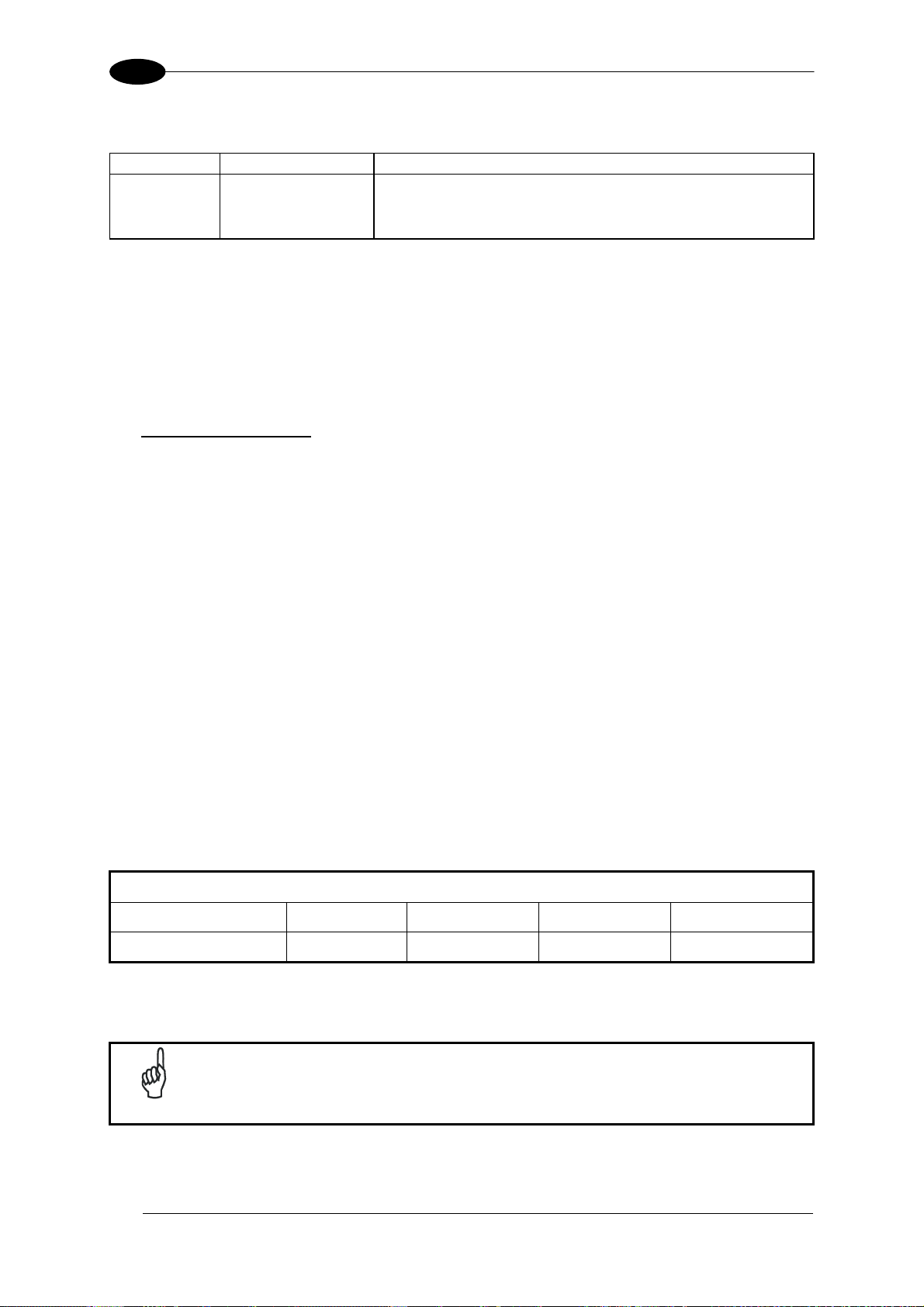
5
DS2100N REFERENCE MANUAL
5.3 ID-NET™ INTERFACE
25-pin Name Function
23 ID+ ID-NET™ network +
24 ID- ID-NET™ network -
7 GND Ground
5.3.1 ID-NET™ Cables
The following instructions are referred to Figure 52, Figure 53 and Figure 54.
• The general cable type specifications are: CAT5 twisted pair + additional CAT5 twisted
pair, shielded cable AWG 24 (or AWG 22) stranded flexible.
We recommend using DeviceNet cables (drop or trunk type) to the following reference
standards:
AN50325 – IEC 62026
UL STYLE 2502 80°C 30V
• Cable Shield MUST be connected to earth ground ONLY at the Master.
• NEVER use ID-NET™ cable shield as common reference.
• The ID-NET™ max cable length depends on the baudrate used, (see the Baudrate Table
below).
• For Common Power Connections use only 2 wires (23 and 24).
- DC Voltage Power cable (Vdc – GND) should be handled as a signal cable (i.e. do not
put it together with AC cable):
- Wire dimensioning must be checked in order to avoid voltage drops greater than 0.8
Volts.
- Cable should lie down as near as possible to the ID-NET™ cable (avoiding wide loops
between them).
• Scanner's chassis may be connected to earth.
• Network inside the same building.
Baudrate Table
Baud Rate 125 kbps 250 kbps
Cable Length 1200 m 900 m
500 kbps
700 m
1Mbps
*
* Application dependent, contact your Datalogic Automation representative for details.
54
NOTE
The default ID-NET™ baudrate is 500 kbps. Lower ID-NET™ baudrates
allow longer cable lengths. The baudrate is software configurable by
authorized Datalogic Automation personnel only.
Page 65
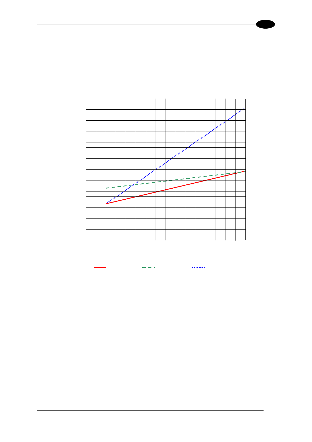
25-PIN CABLE ELECTRICAL CONNECTIONS
5
5.3.2 ID-NET™ Response Time
The following figure shows the response time of the ID-NET™ network. This time is defined
as the period between the Trigger activation and the beginning of data transmission to the
Host.
Max ID-NET™ Response Time
240
220
200
180
160
140
120
100
80
Response Time (ms)
60
40
20
0
0 1 2 3 4 5 6 7 8 9 10 11 12 13 14 15 16
500 kbps 250 kbps
Figure 51 – ID-NET™ Response Time
CONDITIONS:
• ID-NET™ M/S Synchronized layout
• message length = 50 bytes per node
Number of Nodes
125 kbps
55
Page 66
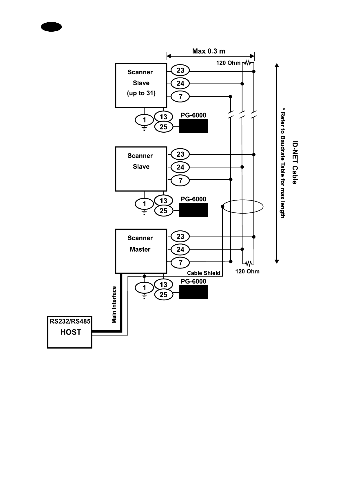
5
DS2100N REFERENCE MANUAL
56
Figure 52 – ID-NET™ Network Connections with isolated power blocks
Page 67
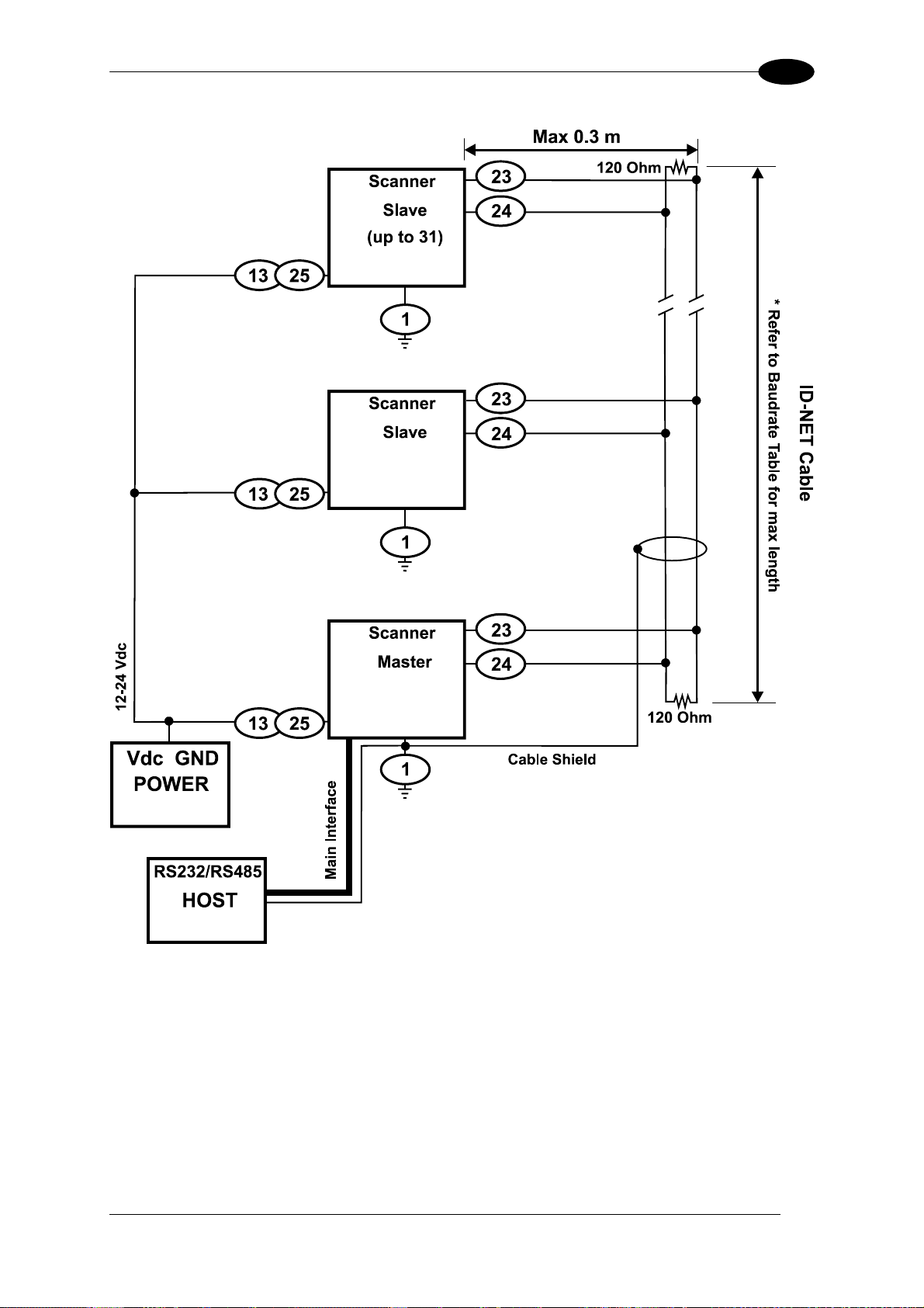
25-PIN CABLE ELECTRICAL CONNECTIONS
5
Figure 53 - ID-NET™ Network Connections with Common Power Branch Network
57
Page 68
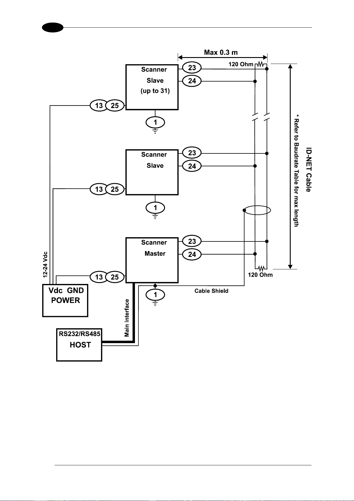
5
DS2100N REFERENCE MANUAL
58
Figure 54 – ID-NET™ Network Connections with Common Power Star Network
Page 69
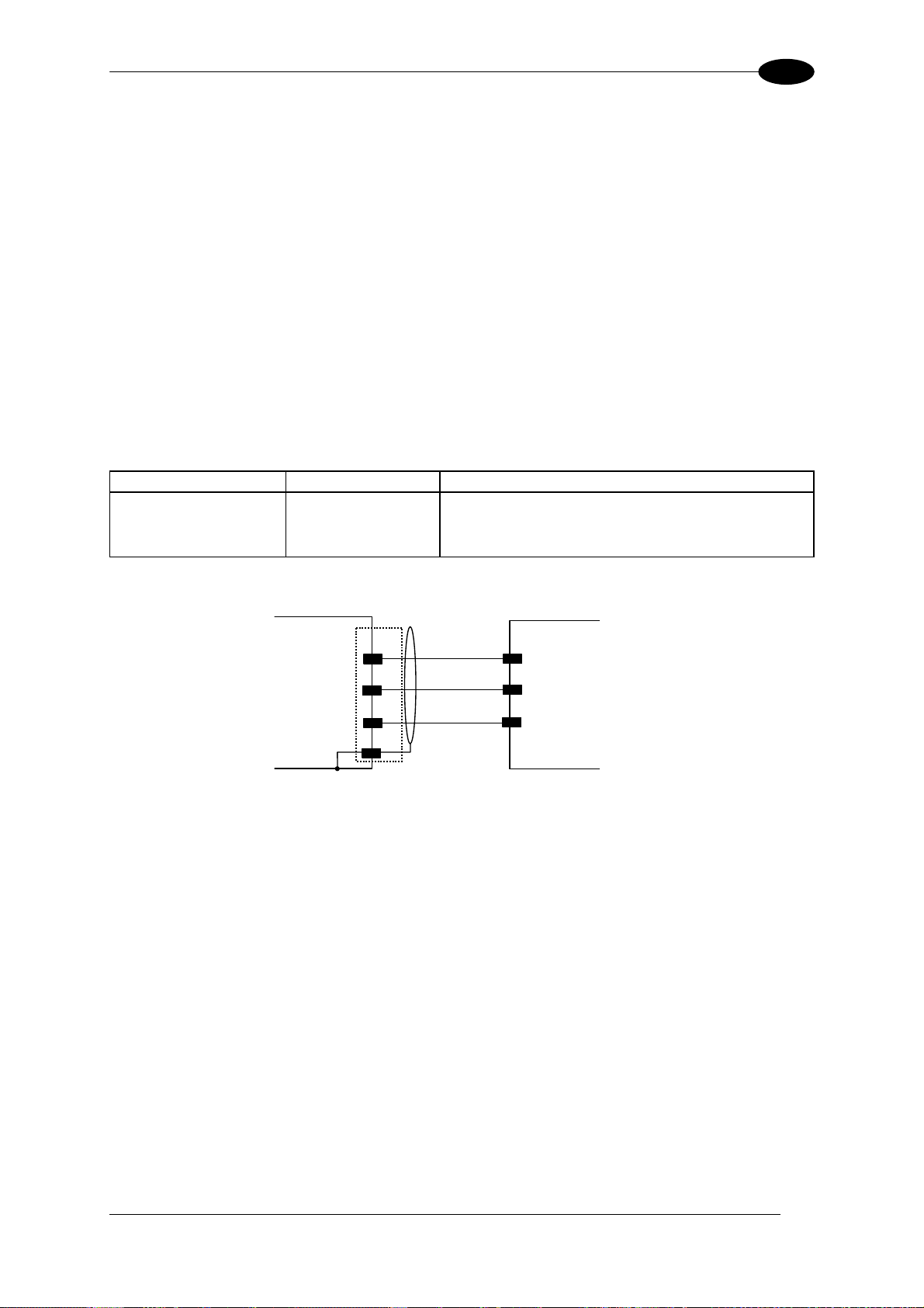
25-PIN CABLE ELECTRICAL CONNECTIONS
5
5.3.3 ID-NET™ Network Termination
The network must be properly terminated by a 120 Ohm resistor at the first and last scanner
of the network.
5.4 AUXILIARY RS232 INTERFACE
The auxiliary serial interface is used exclusively for RS232 point-to-point connections.
The parameters relative to the aux interface (baud rate, data bits, etc.) as well as particular
communication modes such as LOCAL ECHO can be defined using the Genius™ utility
program or Genius™ based Host Mode Programming installed from the CD-ROM.
The following pins of the 25-pin connector are used to connect the RS232 auxiliary interface:
Pin Name Function
20 RX Receive Data
21 TX Transmit Data
7 GND Ground
USER INTERFACEDS2100N
20
Chassis
RX
21
TX
7
GND
1
TXD
RXD
GND
Figure 55 - RS232 Auxiliary Interface Connections
59
Page 70
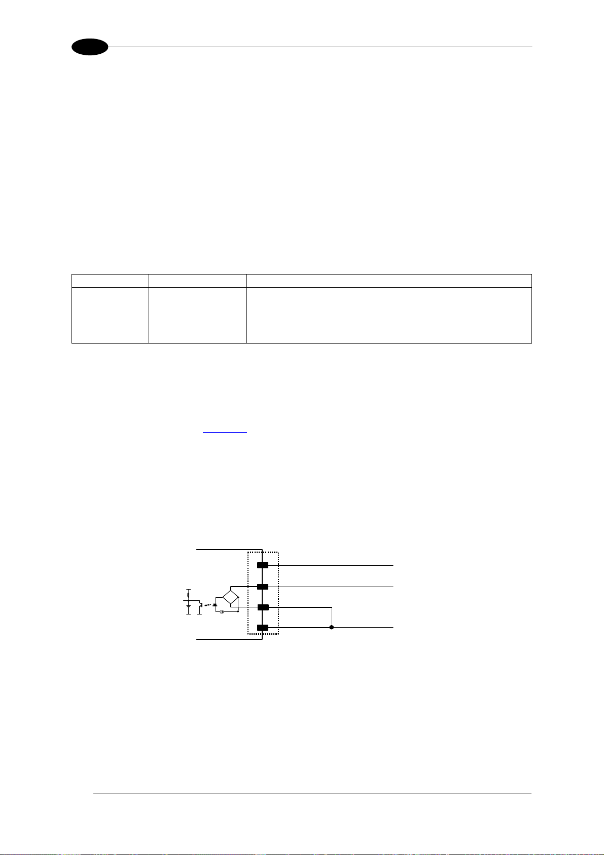
5
DS2100N REFERENCE MANUAL
5.5 INPUTS
There are two optocoupled polarity insensitive inputs available on the scanner: Input 1
(External Trigger) and Input 2, a generic input:
The electrical features of both inputs are:
Maximum voltage: 30 Vdc
Maximum current: 12 mA
An anti-disturbance filter is implemented in software on both inputs so that the minimum
pulse duration is ≅ 5 milliseconds. This value can be increased through the software
parameter Debounce Filter, see the "2K/4K Family Software Configuration Parameter Guide”
Help file".
25-pin
The External Trigger input is used in the On-Line operating Mode and tells the scanner to
scan for a code. The active state of this input is selected in software. Refer to the Genius™
Help On Line.
The yellow Trigger LED (
corresponds to ON.
This input is optocoupled and can be driven by both an NPN and PNP type command. The
connections are indicated in the following diagrams:
Name Function
9 Vdc Power Source - External Trigger
18 I1A External Trigger A (polarity insensitive)
19 I1B External Trigger B (polarity insensitive)
7 GND Power Reference - External Trigger
Figure A, 3) is on when the active state of the External Trigger
EXTERNAL TRIGGER INPUT PNP PH-1
DS2100N
9
Vdc
PNP PH-1 wires
(brown) +10-30 Vdc
60
I1A
VCC
18
~
-
+
~
19
I1B
7
GND
(black) NO
(blue) 0 V
Figure 56 - PH-1 Photocell (PNP) External Trigger Using DS2100N Power
Page 71
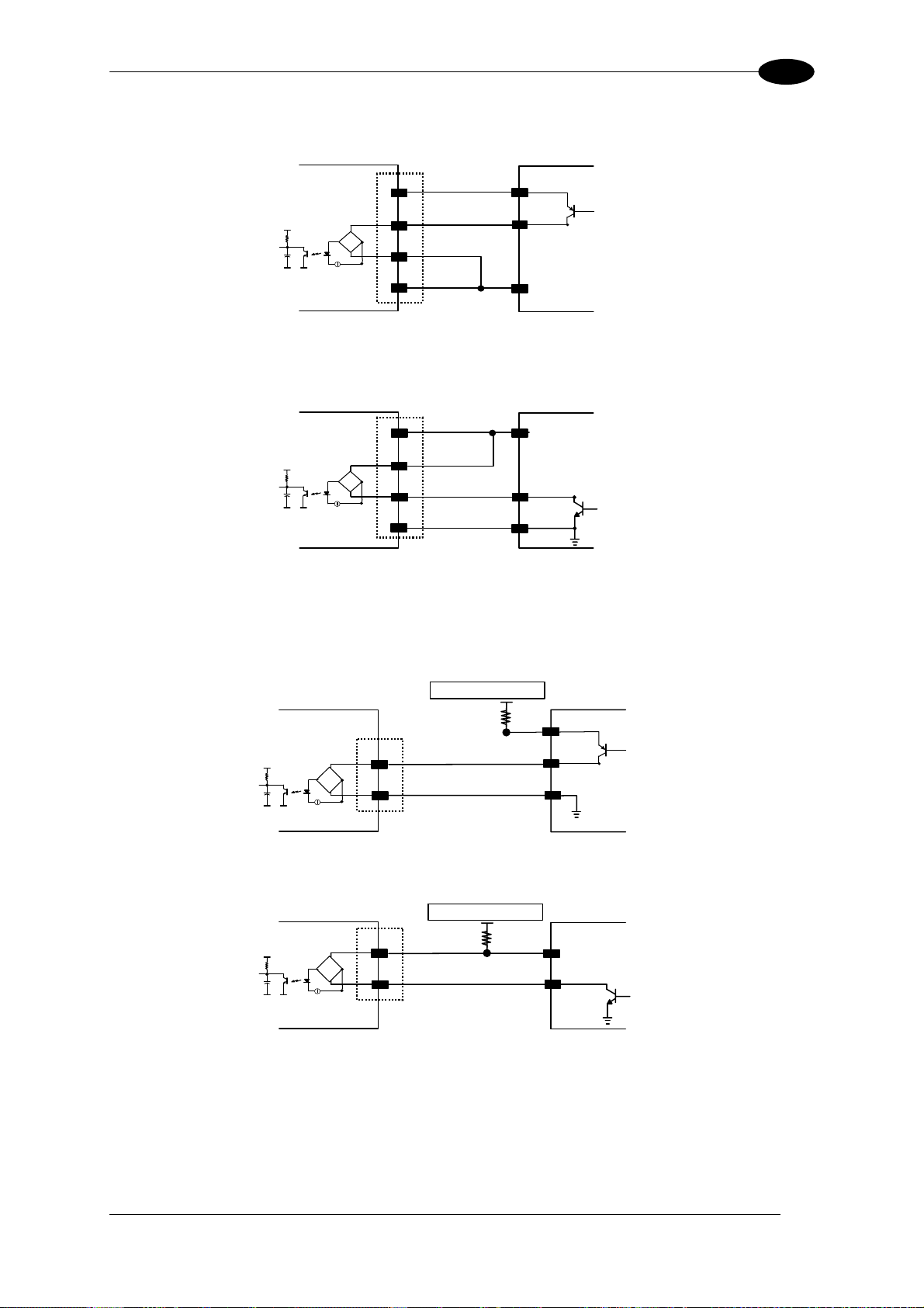
25-PIN CABLE ELECTRICAL CONNECTIONS
5
EXTERNAL TRIGGER INPUT CONNECTIONS USING DS2100N POWER
VCC
DS2100N
~
+
~
9
Vdc
I1A
18
-
19
I1B
7
GND
EXTERNAL TRIGGER
V
Signal
Ground
Figure 57 - PNP External Trigger Using DS2100N Power
DS2100N
VCC
Vdc
9
I1A
18
~
-
+
~
19
I1B
7
GND
EXTERNAL TRIGGER
V
Signal
Ground
Figure 58 - NPN External Trigger using DS2100N Power
EXTERNAL TRIGGER INPUT CONNECTIONS USING EXTERNAL POWER
DS2100N
Vext 30 Vdc max.
EXTERNAL TRIGGER
V
Signal
VCC
18
I1A
~
-
+
~
19
I1B
Figure 59 - PNP External Trigger Using External Power
DS2100N
VCC
Vext 30 Vdc max.
18
I1A
~
-
+
~
19
I1B
EXTERNAL TRIGGER
V
Signal
Figure 60 - NPN External Trigger Using External Power
61
Page 72
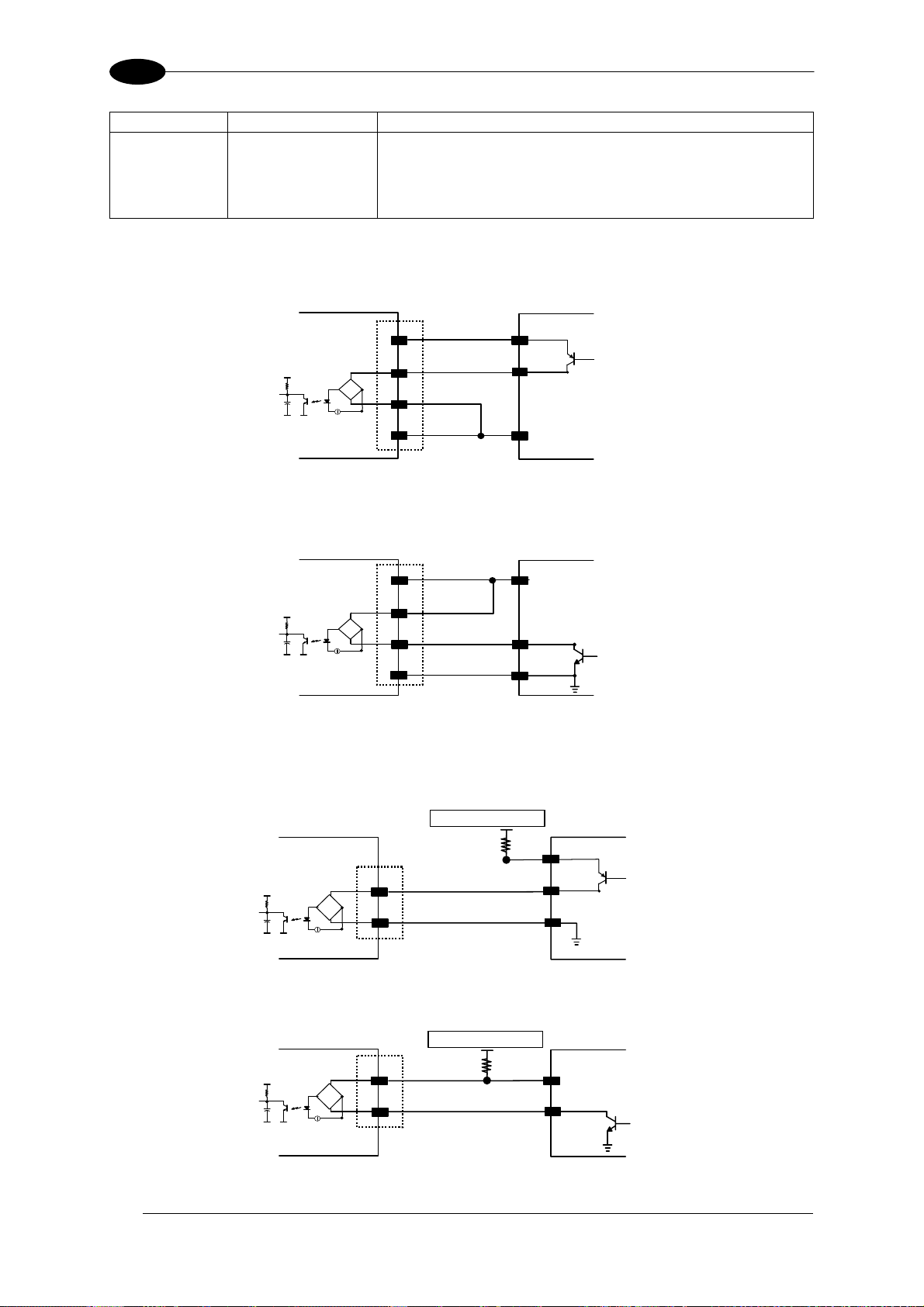
5
25-pin Name Function
9 Vdc Power Source Inputs
6 I2A Input 2 A (polarity insensitive)
10 I2B Input 2 B (polarity insensitive)
7 GND Power Reference - Inputs
INPUT 2 CONNECTIONS USING DS2100N POWER
DS2100N
DS2100N REFERENCE MANUAL
INPUT DEVICE
9
Vdc
V
Signal
VCC
I2A
6
~
-
+
~
10
I2B
7
GND
Ground
Figure 61 - PNP Input 2 Using DS2100N Power
DS2100N
VCC
Vdc
9
I2A
6
~
-
+
~
10
I2B
7
GND
INPUT DEVICE
V
Signal
Ground
Figure 62 - NPN Input 2 Using DS2100N Power
INPUT 2 CONNECTIONS USING EXTERNAL POWER
DS2100N
Vext 30 Vdc max.
EXTERNAL TRIGGER
V
62
Signal
VCC
6
I2A
~
-
+
~
10
I2B
Figure 63 - PNP Input 2 Using External Power
DS2100N
VCC
Vext 30 Vdc max.
6
I2A
~
-
+
~
10
I2B
EXTERNAL TRIGGER
V
Signal
Figure 64 - NPN Input 2 Using External Power
Page 73
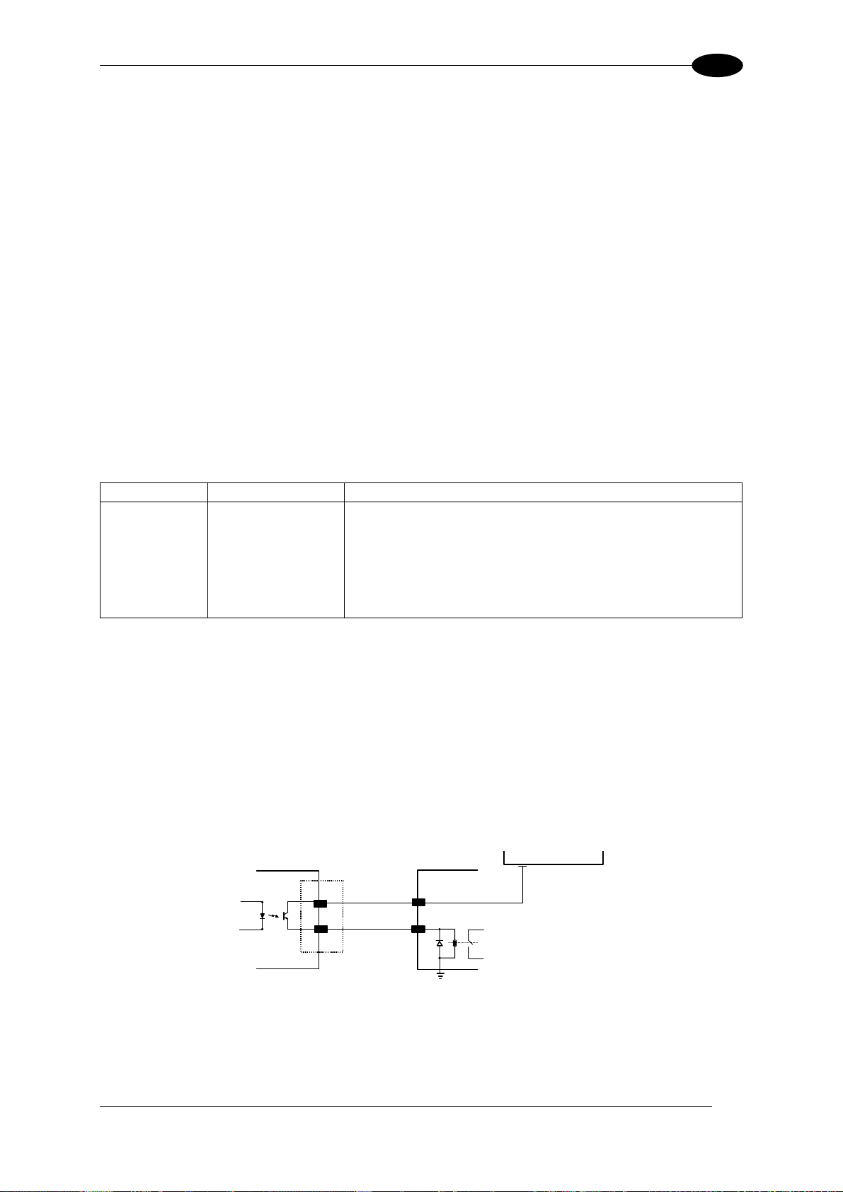
25-PIN CABLE ELECTRICAL CONNECTIONS
V
5
5.5.1 Code Verifier
If the DS2100N is used as a Code Verifier, the verifier code can be configured in software
through the Genius™ configuration program. However it is also possible to use one of the
inputs to trigger when the scanner should store a code read as the verifier code.
The Code Verifier parameter must be enabled, and the configuration parameters to allow
correct Code Type reading must be saved to the scanner in order to read the verifier code.
When the selected input is activated, the next read code will be stored as the verifier code in
the scanner's non-volatile (Flash) memory.
For more details see the Verifier Parameters in the "2K/4K Family Software Configuration
Parameter Guide” Help file".
5.6 OUTPUTS
Two general purpose outputs are available. The following pins are present on the 25-pin
connector of the scanner:
25-pin
The meaning of the two outputs Output 1 and Output 2 can be defined by the user (No Read,
Right, Wrong, etc.). Refer to the Genius™ Help On Line.
By default, Output 1 is associated with the No Read event, which activates when the code
signaled by the external trigger is not decoded, and Output 2 is associated with the Complete
Read event, which activates when all the selected codes are correctly decoded.
The output signals are fully programmable being determined by the configured
Activation/Deactivation events, Deactivation Timeout or a combination of the two.
Name Function
9 Vdc Power Source - Outputs
8 O1+ Output 1 +
22 O1- Output 1 11 O2+ Output 2 +
12 O2- Output 2 -
7 GND Power Reference - Outputs
DS2100N
USER INTERFACE
ext 30 Vdc max.
8/11
C
22/12
E
O+
O-
Figure 65 - Open Emitter Output Connections
63
Page 74

5
V
DS2100N REFERENCE MANUAL
DS2100N
C
E
8/11
22/12
USER INTERFACE
O+
O-
ext 30 Vdc max.
Figure 66 - Open Collector Output Connections
V
max = 30 Vdc
CE
I max = 40 mA continuous; 130 mA pulsed
5.7 USER INTERFACE - HOST
The following table contains the pinout for standard RS232 PC Host interface. For other user
interface types please refer to their own manual.
RS232 PC-side connections
1
5
9 6
9-pin male connector
Pin Name Pin Name
2 RX 3 RX
3 TX 2 TX
5 GND 7 GND
7 RTS 4 RTS
8 CTS 5 CTS
How To Build A Simple Interface Test Cable:
1
25-pin male connector
13
25 14
The following wiring diagram shows a simple test cable including power, external (pushbutton) trigger and PC RS232 COM port connections.
DS2100N
25-pin D-sub male
Trigger
21
20
9-pin D-sub female
TX
RX
GND
7
13
Vdc
25
GND
13
Vdc
18
I1A
19
I1B
Vdc (10 – 30 Vdc)
Power GND
Test Cable for DS2100N
2
3
5
Power Supply
RX
TX
GND
PC
64
Page 75

TYPICAL LAYOUTS
6
6 TYPICAL LAYOUTS
The following typical layouts refer to system
figures refer to optional hardware configurations within the particular layout.
These layouts also require the correct setup of the software configuration parameters.
Complete software configuration procedures can be found in the Guide To Rapid
Configuration in the Genius™ Help On Line.
6.1 POINT-TO-POINT
In this layout the data is transmitted to the Host on the main serial interface. A Genius™
based Host Mode programming can be accomplished either through the main interface or the
Auxiliary interface.
In Local Echo communication mode, data is transmitted on the RS232 auxiliary interface
independently from the main interface selection.
When On-Line Operating mode is used, the scanner is activated by an External Trigger
(photoelectric sensor) when the object enters its reading zone.
hardware configurations. Dotted lines in the
PG6000
DS2100N
CBX
1
2
Terminal
Main Serial Interface (RS232 or RS485 Full-Duplex)
3
Figure 67 – Serial Interface Point-to-Point Layout
Auxiliary Serial Interface (Local Echo) (RS232)
External Trigger (for On-Line Mode)
Host
65
Page 76

6
DS2100N REFERENCE MANUAL
In this layout a single scanner functions as a Slave node on a Fieldbus network. The data is
transmitted to the Host through an accessory Fieldbus interface board installed inside the
CBX500 connection box.
Scanner configuration can be accomplished through the Auxiliary interface using the
Genius™ configuration program or Genius™ based Host Mode programming.
In Local Echo communication mode, data is transmitted on the RS232 auxiliary interface
independently from the Fieldbus interface selection.
When On-Line Operating mode is used, the scanner is activated by an External Trigger
(photoelectric sensor) when the object enters its reading zone.
Power
CBX500
DS2100N
3
Host
1
2
Fieldbus Interface (Profibus, Ethernet, DeviceNet, etc.)
Auxiliary Serial Interface (Local Echo) (RS232)
External Trigger (for On-Line Mode)
Figure 68 – Fieldbus Interface Point-to-Point Layout
66
Page 77

TYPICAL LAYOUTS
6
6.2 PASS-THROUGH
Pass-through mode allows two or more devices to be connected to a single external serial
interface.
Each DS2100N transmits the messages received by the Auxiliary interface onto the Main
interface. All messages will be passed through this chain to the host.
When On-Line Operating mode is used, the scanner is activated by an External Trigger
(photoelectric sensor) when the object enters its reading zone.
Applications can be implemented to connect a device such as a hand-held reader to the
Auxiliary port of the last scanner in the chain for manual code reading capability.
The Main and Auxiliary ports are connected as shown in the figure below:
2 1
2
11
Device#1 Device#2 Device#n
3 3 3
2
Host
Power
Main Serial Interface (RS232 only)
Auxiliary Serial Interface (RS232)
External Trigger (for On-Line Mode)
Figure 69 – Pass-Through Layout
67
Page 78

6
DS2100N REFERENCE MANUAL
An alternative Pass-Through layout allows the more efficient ID-NET™ network to be used.
This layout is really an ID-NET Master/Slave Multidata layout which also allows each
scanner (Master and Slaves) to accept input on the Auxiliary interface, for example to
connect a device such as a hand-held reader for manual code reading capability.
Each DS2100N transmits its own messages plus any messages received by its Auxiliary
interface onto the ID-NET™ interface. The Master passes all messages to the Host.
When On-Line Operating mode is used, the scanner is activated by an External Trigger
(photoelectric sensor) when the object enters its reading zone.
Master Slave#2 Slave#n
4 1
3 3 3
2
Host
Power
2
Main Serial Interface (RS232 or RS485)
Auxiliary Serial Interface (RS232)
External Trigger (for On-Line Mode)
ID-NET™
Figure 70 – Pass-Through On ID-NET™ Layout
68
Page 79

TYPICAL LAYOUTS
6
6.3 ID-NET™
The ID-NET™ connection is used to collect data from several scanners to build a multi-point
or a multi-sided reading system; there can be one master and up to 31 slaves connected
together.
The slave scanners are connected together using the ID-NET™ interface. Every slave
scanner must have a ID-NET™ address in the range 1-31.
The master scanner is also connected to the Host on the RS232/RS485 main serial
interface.
For a Master/Slave Synchronized layout the External Trigger signal is unique to the system;
there is a single reading phase and a single message from the master scanner to the Host
computer. It is not necessary to bring the External Trigger signal to all the scanners.
The main, auxiliary, and ID-NET™ interfaces are connected as shown in the figure below.
1 3
2
Master
Power
Host
Slave#1 Slave#n
Main Serial Interface (RS232 or RS485)
External Trigger (for On-Line Mode)
ID-NET™ (up to 16 devices - practical limit)
Figure 71 – ID-NET™ M/S Synchronized Layout
69
Page 80
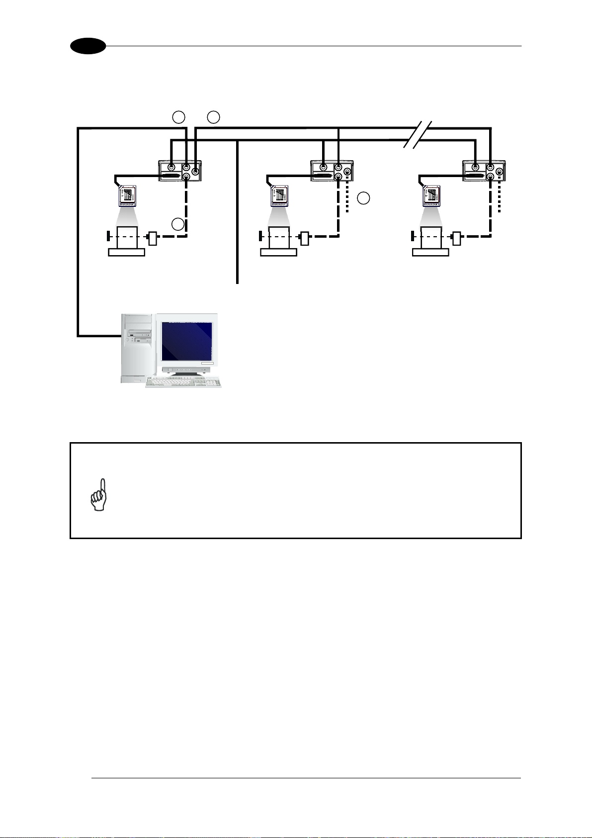
6
DS2100N REFERENCE MANUAL
For a Master/Slave Multidata layout each scanner has its own reading phase independent
from the others; each single message is sent from the master scanner to the Host computer.
Master Slave#1 Slave#n
1 4
2
Terminal
3
Power
Host
Main Serial Interface (RS232 or RS485)
Auxiliary Serial Interface (Local Echo) (RS232)
External Trigger (for On-Line Mode)
ID-NET™ (up to 32 devices, max network extension of 1000 m)
Figure 72 – ID-NET™ M/S Multidata
The auxiliary serial interface of the slave scanners can be used in Local Echo
communication mode to control any single scanner (visualize collected data)
or to configure it using the Genius™ utility or the Genius™ based Host Mode
programming procedure.
NOTE
The ID-NET™ termination resistor switches must be set to ON only in the first
and last CBX connection box.
70
Page 81
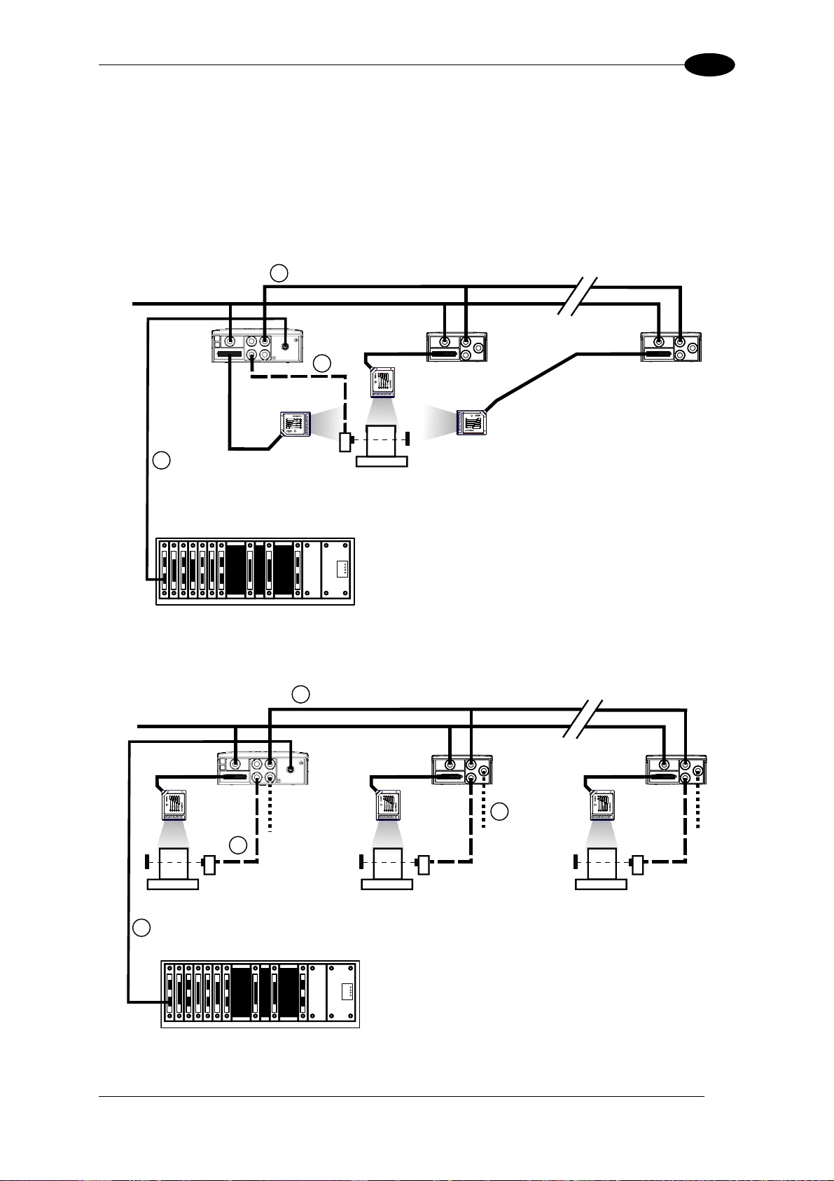
TYPICAL LAYOUTS
6
Alternatively, the Master scanner can communicate to the Host as a Slave node on a
Fieldbus network. This requires using an accessory Fieldbus interface board installed inside
the CBX500 connection box.
System configuration can be accomplished through the Auxiliary interface of the Master
scanner (internal CBX500 9-pin connector) using the Genius™ configuration program or
Genius™ based Host Mode programming.
Power
Master
1
3
Slave#1 Slave#n
2
Host
Fieldbus Interface
External Trigger (for On-Line Mode)
ID-NET™ (up to 16 devices - practical limit)
Figure 73 – ID-NET™ Fieldbus M/S Synchronized Layout
Power
Master Slave#1 Slave#n
3
1
Host
4
2
Terminal
Fieldbus Interface
Auxiliary Serial Interface (Local Echo) (RS232)
External Trigger (for On-Line Mode)
ID-NET™ (up to 32 devices, max network extension of 1000 m)
Figure 74 – ID-NET™ Fieldbus M/S Multidata
71
Page 82
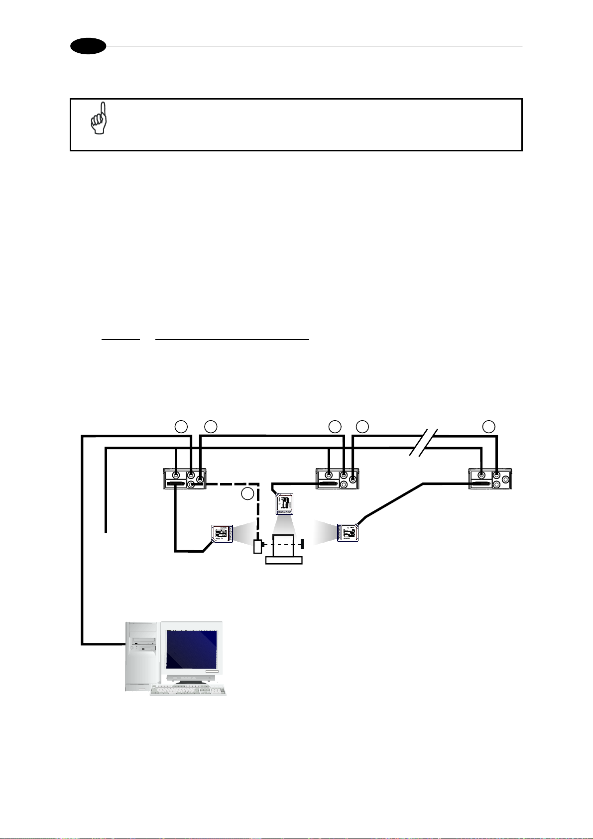
6
DS2100N REFERENCE MANUAL
6.4 RS232 MASTER/SLAVE
This interface is provided for backward compatibility. We recommend using
NOTE
The RS232 master/slave connection is used to collect data from several scanners to build
either a multi-point or a multi-sided reading system; there can be one master and up to 9
slaves connected together.
The Slave scanners use RS232 only on the main and auxiliary serial interfaces. Each slave
DS2100N transmits the messages received by the auxiliary interface onto the main interface.
All messages will be passed through this chain to the Master.
The Master scanner is connected to the Host on the RS232/RS485 main serial interface.
There is a single reading phase and a single message from the master scanner to the Host
computer.
Either
On-Line or Serial On-Line Operating modes can be used in this layout.
When On-Line Operating mode is used, the external trigger signal is unique to the
system, however it is not necessary to bring the external trigger signal to the Slave
scanners.
The main and auxiliary ports are connected as shown in the figure below.
the more efficient ID-NET™ network for Master/Slave or Multiplexer layouts.
2 1
2
11
Power
Master
Host
Slave#1 Slave#n
3
Main Serial Interface (RS232 only)
Auxiliary Serial Interface (RS232)
External Trigger (for On-Line Mode)
Figure 75 – RS232 Master/Slave Layout
72
Page 83
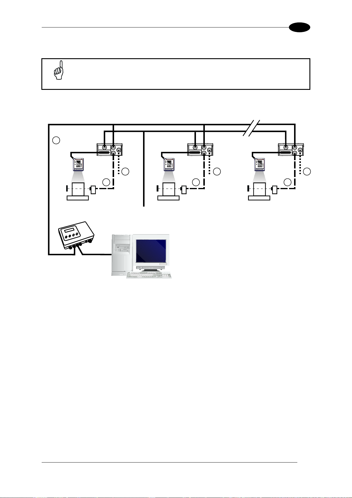
TYPICAL LAYOUTS
6
6.5 MULTIPLEXER LAYOUT
This interface is provided for backward compatibility. We recommend using
NOTE
Each scanner is connected to a Multiplexer (for example MX4000) with the RS485 halfduplex main interface through a CBX connection box.
1
the more efficient ID-NET™ network for Master/Slave or Multiplexer layouts.
0
1 31
MX4000
2
3
Power
3 3
Main Serial Interface (RS485 Half-Duplex)
Host
Auxiliary Serial Interface (Local Echo) (RS232)
2 2
External Trigger (for On-Line Mode)
Figure 76 - Multiplexer Layout
The auxiliary serial interface of the slave scanners can be used in Local Echo communication
mode to control any single scanner (visualize collected data) or to configure it using the
Genius™ utility or Genius™ based Host Mode programming procedure.
Each scanner has its own reading phase independent from the others. When On-Line
Operating mode is used, the scanner is activated by an External Trigger (photoelectric
sensor) when the object enters its reading zone.
73
Page 84
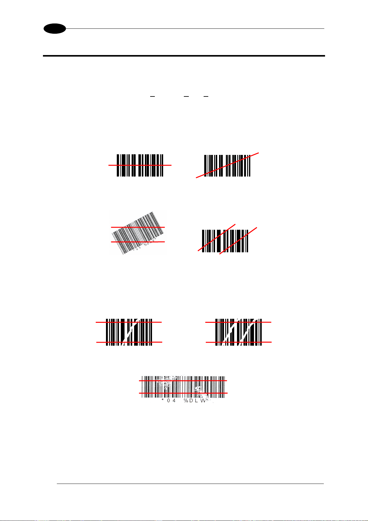
7
DS2100N REFERENCE MANUAL
7 READING FEATURES
7.1 ADVANCED CODE BUILDER (ACB)
In addition to linear reading, the
“stitching” together two partial reads of it. ACB is not as powerful as Advanced Code
Reconstruction due to limits on tilt angle, speed and Multi-label function; but it is effective in
the case of close-to-linear, small height codes, damaged codes, or poor print quality codes.
ACB is used to read a code label when the scan line does not cross the label along its entire
length (excessive tilt angle).
Advanced Code Builder (ACB) allows code reading by
Linear Reading
Linear Reading
ACB Reading
ACB Reading
ACB reads two fragments of a label containing a start or a stop character and a number of
digits, and puts them together to build the complete label.
ACB also has an intrinsic ability to increase the reading percentage of damaged codes as in
the examples below:
ACB Readable
Not ACB Readable
ACB Readable
ACB is disabled by default but can be enabled for the following code types:
• Code 25 Interleaved • Code 128/EAN128
• Code 39 Family • EAN/UPC (without ADD-Ons)
• Codabar • Code 93
74
Page 85
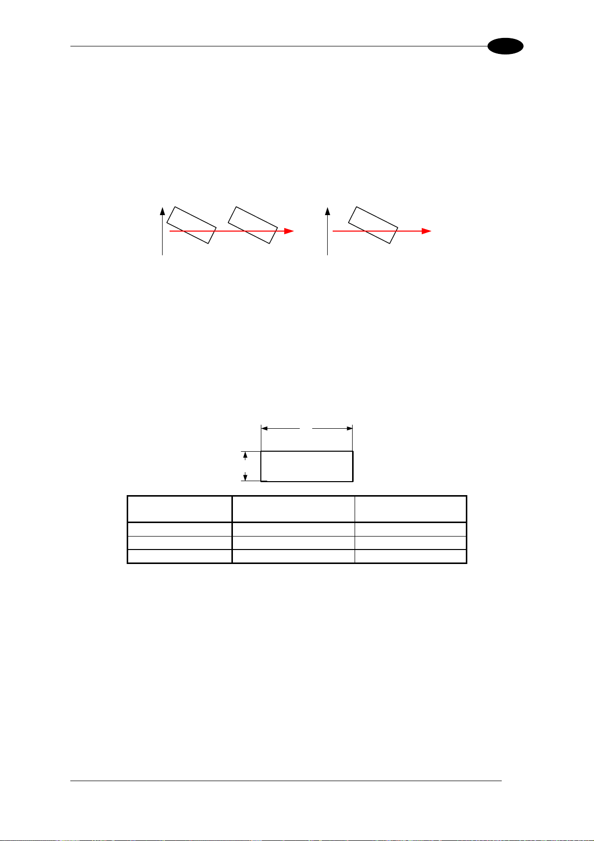
READING FEATURES
7.1.1 Important ACB Reading Conditions
• Do not use ACB for omni-directional reading stations.
• ACB can be activated for each symbology independently from the others.
• ACB requires that the code be in movement with respect to the scanner.
• ACB requires fixed length barcode reading.
• The codes read with ACB enabled must pass in front of the scanner one at a time.
7
Not valid for ACB
Valid for ACB
• Code concatenation and ACB are not compatible and therefore cannot be enabled
simultaneously on the same code.
• For correct operation, ACB requires at least 5 scans for each of the two fragments.
7.1.2 Tilt Angle Improvement with ACB
ACB allows barcode reading with an increased tilt angle. The tilt angle depends upon the
code aspect ratio defined as H/L according to the table below:
H
L
barcode label
Aspect Ratio
H/L
Max theoretical linear
tilt angle
Max practical
ACB angle
0.33 18° 30°
0.25 14° 23°
0.125 7° 11°
7.2 LINEAR CODE READING
The number of scans performed on the code by the DS2100N and therefore the decoding
capability is influenced by the following parameters:
• number of scans per second
• code motion speed
• label dimensions
• scan direction with respect to code motion
At least 5 scans during the code passage should be allowed to ensure a successful read.
75
Page 86
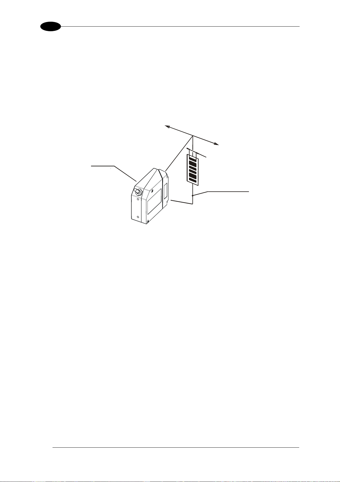
7
DS2100N REFERENCE MANUAL
7.2.1 Step-Ladder Mode
If scanning is perpendicular to the code motion direction (Figure 77), the number of effective
scans performed by the reader is given by the following formula:
SN = [(LH/LS) * SS] – 2 Where: SN = number of effective scans
LH = label height (in mm)
LS = label movement speed in (mm/s)
SS = number of scans per second
Direction of code
movement at LS speed
DS2100N
LH
Laser beam
Figure 77 - "Step-Ladder" Scanning Mode
For example, the DS2100N (500 scans/sec.) for a 25 mm high code moving at 1000 mm/s
performs:
[(25/1000) * 500] - 2 = 10 effective scans.
76
Page 87
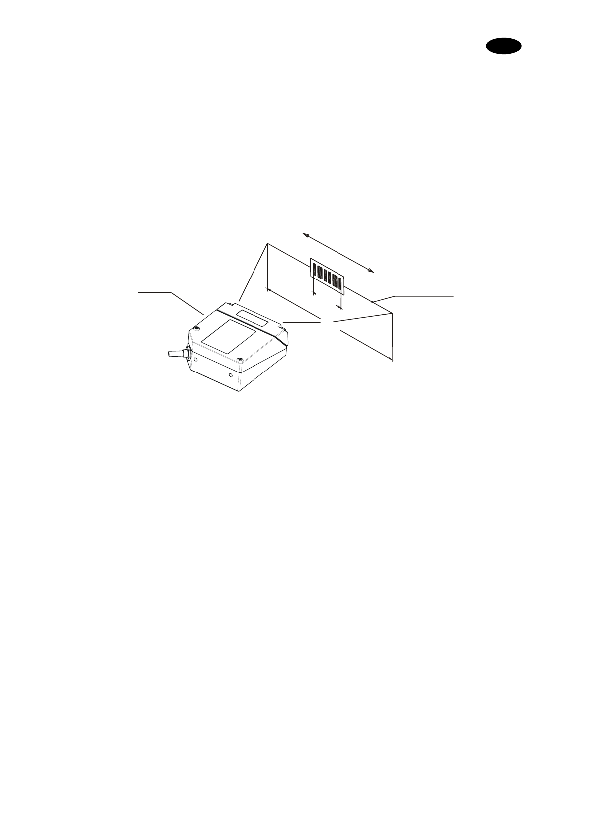
READING FEATURES
7
7.2.2 Picket-Fence Mode
If scanning is parallel to the code motion, (Figure 78), the number of effective scans is given
by the following formula:
SN = [((FW-LW)/LS) * SS] -2 Where: SN = number of effective scans
FW = reading field width (in mm)
LW = label width (in mm)
LS = label movement speed (in mm/s)
SS = scans per second
Direction of code m
at LS speed
ovement
DS2100N
LW
FW
Laser beam
Figure 78 - "Picket-Fence" Scanning Mode
For example, for a 60 mm wide code moving in a point where the reading field is 160 mm
wide at a 1500 mm/s speed, the DS2100N (500 scans per sec.), performs:
[((160-60)/1500) * 500] - 2 = 31 effective scans
77
Page 88
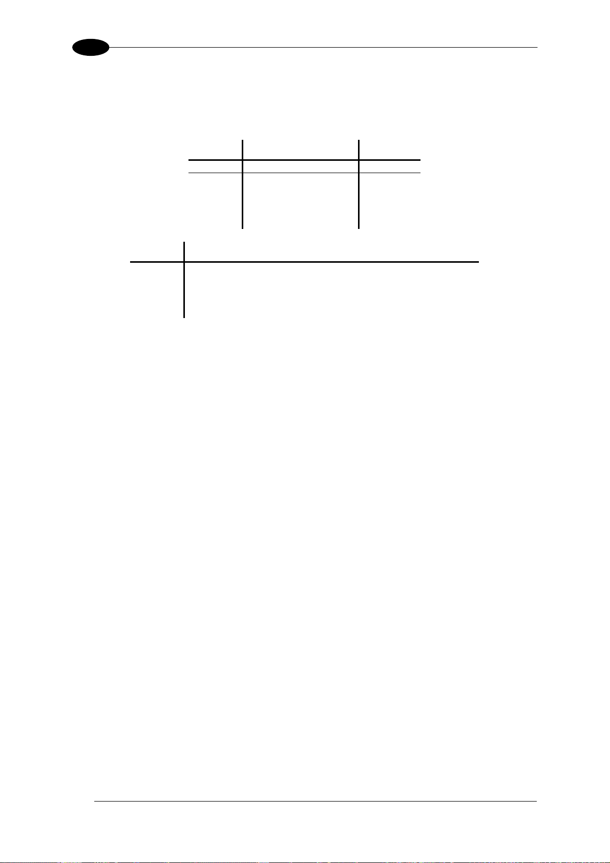
7
DS2100N REFERENCE MANUAL
7.3 PERFORMANCE
The DS2100N scanner is available in different versions according to the reading
performance.
Version Max Code Resolution Speed
mm (mils) scans/s
12X0 0.20 (8) 500 to 800
12X4 0.15 (6) 800 to 1000
22X0 0.15 (6) 500 to 800
22X4 0.12 (5) 800 to 1000
Version Reading Distance
12X0 40 mm (1.6 in) - 300 mm (11.8 in) on 0.50 mm (20 mils) codes
12X4 50 mm (1.8 in) - 310 mm (11.8 in) on 0.50 mm (20 mils) codes
22X0 30 mm (1.2 in) - 90 mm (3.5 in) on 0.30 mm (12 mils) codes
22X4 45 mm (1.8 in) - 100 mm (3.9 in) on 0.20 mm (8 mils) codes
Refer to the diagrams given in par. 7.4 for further details on the reading features. They are
taken on various resolution sample codes at a 25 °C ambient temperature, depending on the
conditions in the notes under the diagrams.
7.3.1 Raster
Raster versions are available. The distance between the top and bottom scan lines is called
capture and is measured from the laser beam output window.
The maximum capture is 18 mm (0.7 in) at 300 mm (11.8 in).
If standard devices do not satisfy specific requirements, contact your nearest Datalogic
distributor, supplying code samples, to obtain complete information on the reading
possibilities.
78
Page 89
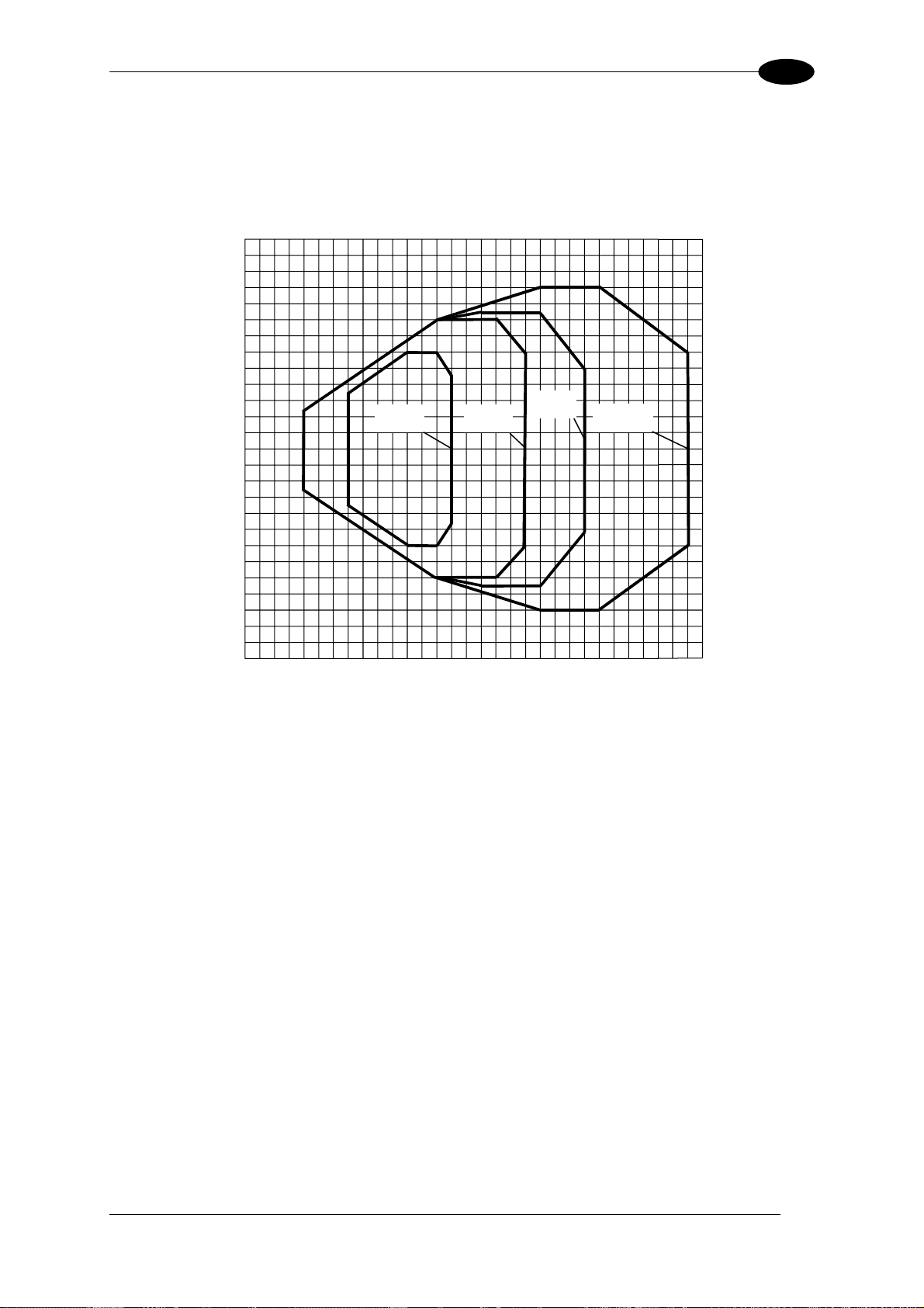
READING FEATURES
7.4 READING DIAGRAMS
DS2100N-1200 (Standard Resolution)
5
4
3
2
1
0
1
2
3
0 1 3 2 106
0 20 40 60 80 100 120 140 160 180 200 220 240 260
120
100
80
60
40
20
0
20
40
60
80
45 789
0.20 mm
(8 mils)
0.30 mm
(12 mils)
0.35 mm
(14 mils)
0.50 mm
≥
(20 mils)
11
280
12
300
7
(in)
(mm)
100
4
120
5
(mm)
(in)
NOTE: (0,0) is the center of the laser beam output window.
CONDITIONS
Optic Version = Linear
Code = Interleaved 2/5 or Code 39
PCS = 0.90
"Pitch" angle =
"Skew" angle =
"Tilt" angle =
0°
15°
0°
*Reading Conditions = Standard
*Scan Speed = 500 scans/sec
* Parameter selectable in Genius™
79
Page 90

7
DS2100N REFERENCE MANUAL
DS2100N-1200
Reading Distance vs Scanning Speed
Distance
Resolution
0.50 mm
0.35 mm
0.30 mm
0.20 mm
Code
0 1 3 2 106
0 20 40 60 80 100 120 140 160 180 200 220 240 260
45 7 8 9
11
500 scans/s
800 scans/s
280
12
300
(in)
(mm)
80
Page 91
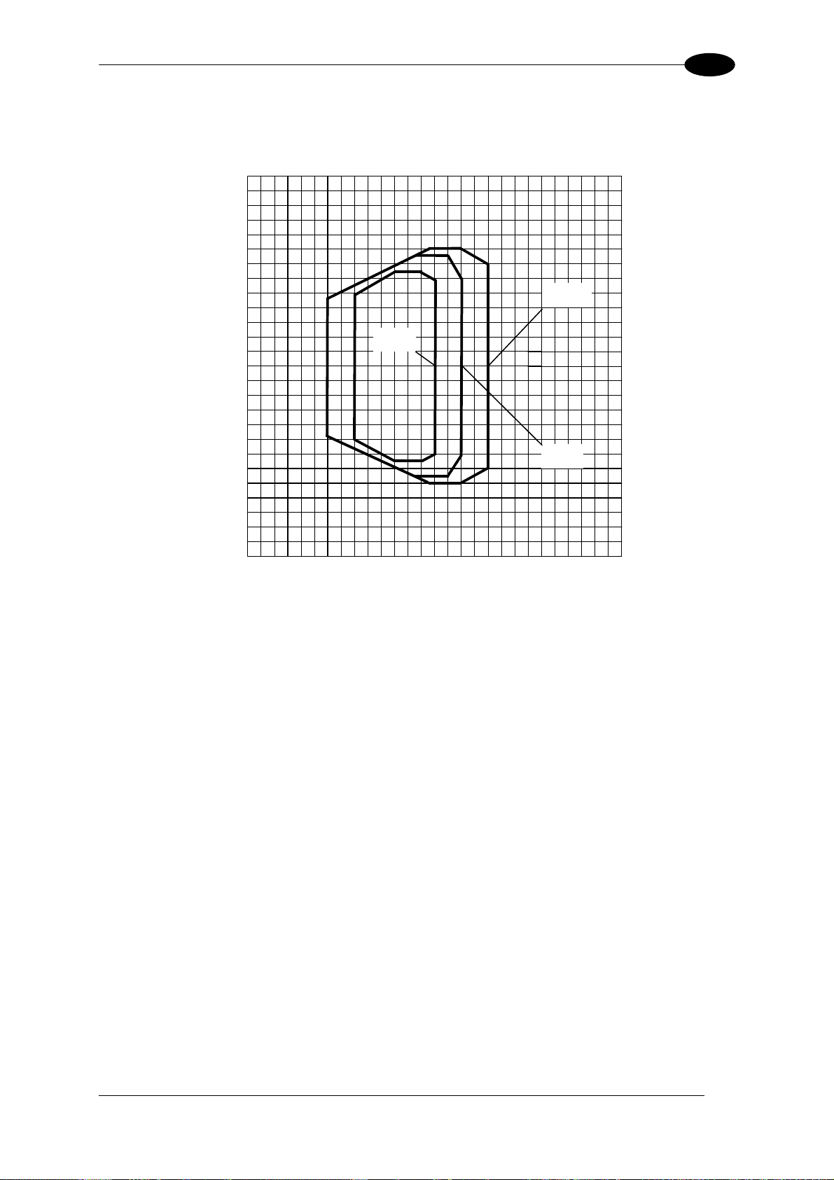
READING FEATURES
(
)
DS2100N-2200 (High resolution)
2
01 53
0
10
20
30
60
50
40
24
40
50 60
70 80
90
100
110
120
130
7
(in)
(mm)
30
1
20
0.15 mm
(6 mils)
0
1
2
(in)
10
0
10
20
30
40
50
60
(mm)
NOTE: (0,0) is the center of the laser beam output window.
CONDITIONS
Optic Version = Linear
Code = Interleaved 2/5 or Code 39
PCS = 0.90
"Pitch" angle =
"Skew" angle =
"Tilt" angle =
0°
15°
0°
*Reading Conditions = Standard
*Scan Speed = 500 scans/sec
* Parameter selectable in Genius™
0.30 mm
≥
12 mils
0.20 mm
(8 mils)
81
Page 92

7
DS2100N REFERENCE MANUAL
DS2100N-2200
Reading Distance vs Scanning Speed
Distance
0.30 mm
0.20 mm
0.15 mm
Code
Resolution
0 1 5 3
0
10
20
30
24
40
50 60
70 80
90
100
110
500 scans/s
800 scans/s
120
130
(in)
(mm)
82
Page 93

READING FEATURES
DS2100N-1204 High Performance (Standard Resolution)
5
4
3
2
1
0
1
2
3
0 1 3 2 106
0 20 40 60 80 100 120 140 160 180 200 220 240 260
120
100
80
60
40
20
0
20
40
60
80
45 789
0.15 mm
(6 mils)
0.20 mm
(8 mils)
0.30 mm
(12 mils)
11
280
0.50 mm
≥
(20 mils)
12
300
7
(in)
(mm)
100
4
120
5
(mm)
(in)
NOTE: (0,0) is the center of the laser beam output window.
CONDITIONS
Optic Version = Linear
Code = Interleaved 2/5 or Code 39
PCS = 0.90
"Pitch" angle =
"Skew" angle =
"Tilt" angle =
0°
15°
0°
*Code Resolution = High for 0.30 mm, (12 mils) codes and smaller
Standard for 0.50 mm (20 mils) codes and greater
*Reading Conditions = Standard
*Scan Speed = 1000 scans/sec
* Parameter selectable in Genius™
83
Page 94

7
(
DS2100N-2204 High Performance (High Resolution)
2
0 1 5 3
0
10
20
30
60
50
40
24
40
50 60
70 80
DS2100N REFERENCE MANUAL
(in)
90
100
110
120
130
(mm)
1
0
1
2
(in)
30
20
10
0
10
20
30
40
50
60
(mm)
0.12 mm
(5 mils)
0.20 mm
≥
8 mils)
0.15 mm
(6 mils)
NOTE: (0,0) is the center of the laser beam output window.
CONDITIONS
Optic Version = Linear
Code = Interleaved 2/5 or Code 39
PCS = 0.90
"Pitch" angle =
"Skew" angle =
"Tilt" angle =
0°
15°
0°
*Code Resolution = High for 0.15 mm, (6 mils) codes and smaller
Standard for 0.20 mm (8 mils) codes
*Reading Conditions = Standard
*Scan Speed = 1000 scans/sec
* Parameter selectable in Genius™
84
Page 95

MAINTENANCE
8
8 MAINTENANCE
8.1 CLEANING
Clean the laser beam output window periodically for continued correct operation of the
reader.
Dust, dirt, etc. on the window may alter the reading performance.
Repeat the operation frequently in particularly dirty environments.
Use soft material and alcohol to clean the window and avoid any abrasive substances.
Clean the window of the DS2100N when the scanner is turned off or, at
least, when the laser beam is deactivated.
WARNING
85
Page 96

9
DS2100N REFERENCE MANUAL
9 TROUBLESHOOTING
9.1 GENERAL GUIDELINES
When wiring the device, pay careful attention to the signal name (acronym) on the
CBX100/500 spring clamp connectors (chp. 4). If you are connecting directly to the scanner
25-pin connector pay attention to the pin number of the signals (chp 5).
If you need information about a certain reader parameter you can refer to the Genius™
program help files.
Either connect the device and select the parameter you’re interested in by pressing the F1
key, or select Help/Parameters Help/2K_4K Software Configuration Parameters Guide
from the command menu.
If you’re unable to fix the problem and you’re going to contact your local Datalogic office or
Datalogic Partner or ARC, we suggest providing (if possible) the Device Configuration files
(*.ddc). Connect through Genius™ and click the Save icon from the toolbar. Also note the
exact Model, Serial Number and Order Number of the device.
86
Page 97

TROUBLESHOOTING
TROUBLESHOOTING GUIDE
Problem Suggestions
Power On:
the “Power
On”/”Ready” LED is not
lit
Is power connected?
If using a power adapter (like PG 6000), is it connected to a wall
outlet?
If using rail power, does rail have power?
If using CBX100, does it have power (check switch and LED)?
Measure voltage either at pin 13 and pin 25 (for 25-pin
connector) or at spring clamp Vdc and GND (for CBX).
On line Mode:
TRIGGER LED is not lit
(when external trigger
activates)
Is sensor connected to I1A, I1B spring clamps (for CBX) or to
pins 18 and 19 (for 25-pin connector)?
Is power supplied to photo sensor?
Are the photo sensor LEDS (if any) working correctly?
Is the sensor/reflector system aligned?
On line Mode:
TRIGGER LED is
correctly lit but nothing
happens (no reading
results)
Serial On line Mode:
the reader is not
triggered (no reading
results)
Is the software configuration consistent with the application
condition (operating mode etc.)?
In the Genius™ program select the Operating Mode branch and
check for related parameters.
In the Genius™ program select the Operating Mode branch and
check if Serial On Line is selected in the On Line Options.
Are the Start – Stop characters correctly assigned?
Is the serial trigger source correctly connected and configured?
On line Mode and
Serial On Line:
Reader doesn’t
In the Genius™ program select the Operating Mode branch and
check the Reading Phase Timeout parameterization.
respond correctly to the
expected external
signals end
X-PRESS™:
X-PRESS™ functions
don't work. LEDs light
up but do not allow
access to the functions.
The X-PRESS™ functions don't work if the scanner motor or
laser are turned off. Check if the motor or laser are turned off
through the following parameters:
• Beam Shutter = enabled
• Scan Speed = Motor Off
• Energy Saving>Serial Motor Off has been sent
9
87
Page 98

9
TROUBLESHOOTING GUIDE
Problem Suggestions
Reading:
Not possible to read the
target barcode (always
returns No Read) or the
Auto Setup procedure
Fails.
Check synchronization of reading pulse with object to read:
Is the scan line correctly positioned?
Place barcode in the center of scan line and run Test mode
(selectable by Genius™ as an Operating Mode). If you still have
trouble, check the following:
• Is the reading distance within that allowed (see reading
diagrams)?
• Is the Tilt angle too large?
• Is the Skew angle less than 10° (direct reflection)?
• Choose the Code Definition branch and enable different
Code Symbologies (except Pharmacode). Length = Min
and Max (variable).
• Is the Bar Code quality sufficient?
If you had no success, try to perform the test using the
BARCODE TEST CHART included with the product.
Communication:
Device is not
transmitting anything to
the host
• Is the serial cable connected?
• Is the correct wiring respected?
• Are serial host settings equivalent to the serial device
setting?
• If using CBX, be sure the RS485 termination switch is
positioned to OFF.
Communication:
Data transferred to the
host are incorrect,
corrupted or incomplete
• In the Genius™ program select the Data Communication
Settings/Data Format/Standard Parameters branch and
check the Header, Separators, and Terminator values
• Also check the Code Field Length and Fill Character values.
• Are the COM port parameters correctly assigned?
Communication:
Always returns the
Reader Failure
Character (<BEL> char
• Contact your local Datalogic office or Datalogic Partner or
ARC, because either a Motor or Laser failure has occurred.
• Note the exact model and Serial Number of the device.
as default)
How do I obtain my
units’ serial
numbers?
• The device’s serial number is printed on a label that is affixed
to the body of the reader.
• Serial numbers consist of 9 characters: one letter, 2
numbers, and another letter followed by 5 numbers.
DS2100N REFERENCE MANUAL
88
Page 99
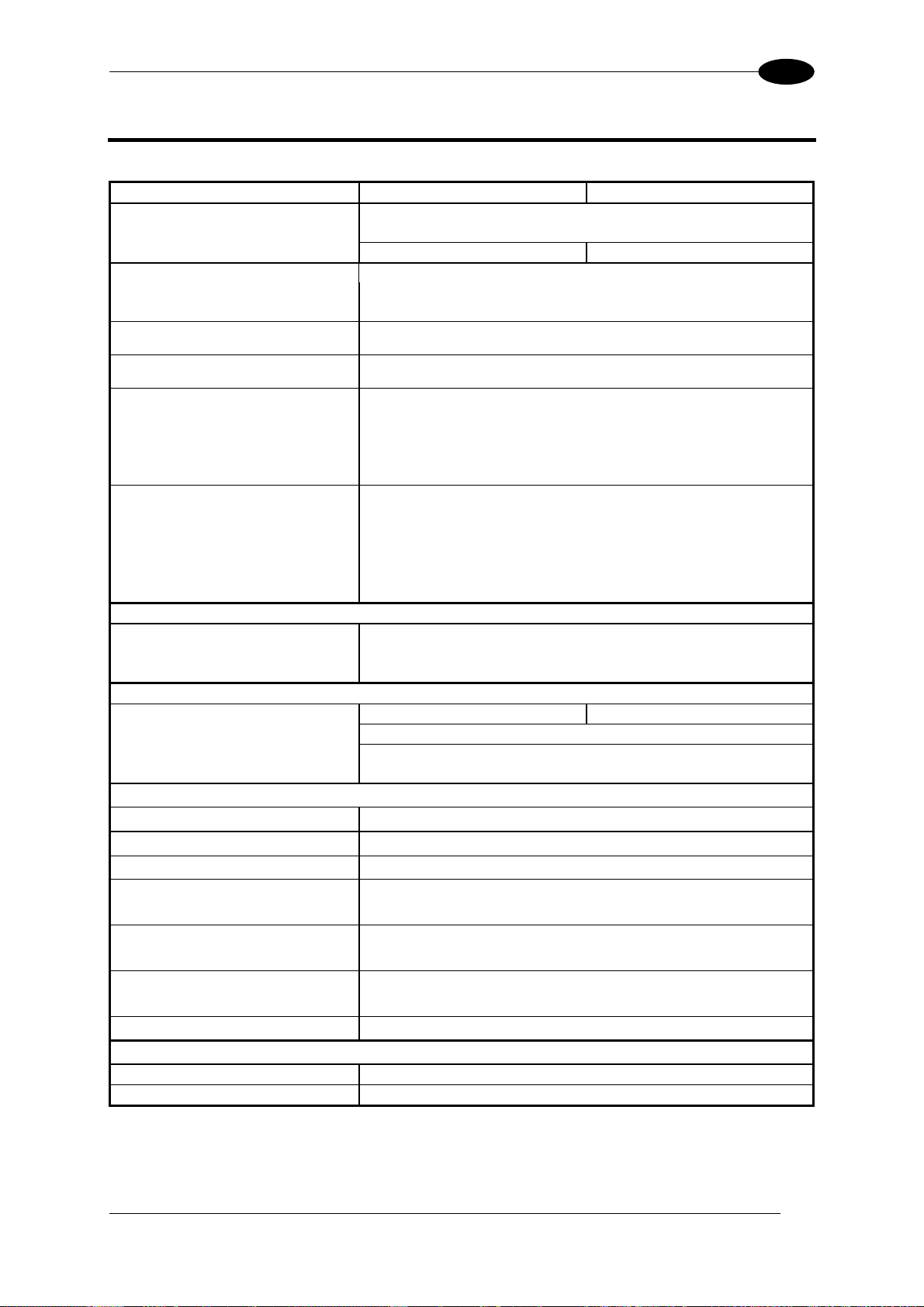
TECHNICAL FEATURES
10
10 TECHNICAL FEATURES
ELECTRICAL FEATURES DS2100N-XXX0 DS2100N-XXX4
Input Power
Supply Voltage 10 to 30 Vdc
Power consumption max. 0.3 to 0.1 A; 3 W 0.5 to 0.17 A; 5 W
Serial Interfaces
Main Serial Interface Sw programmable: RS232; RS485 FD and HD
Baudrate 1200 - 115200
Auxiliary RS232
Baudrate 1200 - 115200
ID-NET™ RS485 Half-duplex
Baudrate Up to 1 MBaud
Inputs
Input 1 (External Trigger), Input 2 Optocoupled, polarity insensitive
Voltage 10 to 30 Vdc
Current Consumption 12 mA max.
Minimum Pulse Duration 5 ms.
Outputs
Output 1, Output 2 Optocoupled
V
CE
Collector Current 40 mA continuous max.; 130 mA pulsed max.
V
CE saturation
Power Dissipation
OPTICAL FEATURES
Light Source Semiconductor laser diode
Wave Length In the range 630 to 680 nm
Safety Class Class 2 - EN 60825-1; Class II - CDRH
READING FEATURES (Note 1)
Scan Rate (software program.) (500 to 800 scans/sec) (800 to 1000 scans/sec)
Aperture Angle 50°
Maximum Reading Distance
Maximum Resolution
ENVIRONMENTAL FEATURES
Operating Temperature (Note 2)
Storage Temperature
Humidity max. 90% non condensing
Vibration Resistance 14 mm @ 2 to 10 Hz; 1.5 mm @ 13 to 55 Hz;
EN 60068-2-6 2 g @ 70 to 200 Hz; 2 hours on each axis
Bump Resistance 30g; 6 ms;
EN 60068-2-29 5000 shocks on each axis
Shock Resistance 30g; 11 ms;
EN 60068-2-27 3 shocks on each axis
Protection Class – EN 60529 IP65
PHYSICAL FEATURES
Mechanical Dimensions 68 x 84 x 34 mm (2.7 x 3.3 x 1.3 in)
Weight 330 g (11.6 oz.)
Note 1: Further details given in par. 7.3.
Note 2: If the reader is used in high temperature environments (over 40 °C), use of the Beam Shutter is advised (see the
Genius™ configuration program) and/or a thermally conductive support (such as the metal bracket provided).
30 Vdc max.
1V max. at 10 mA
80 mW max. at 45
See reading diagrams
0° to +45
-20° to +70
°C (ambient temperature)
°C (+32° to +113 °F)
°C (-4° to +158 °F)
89
Page 100
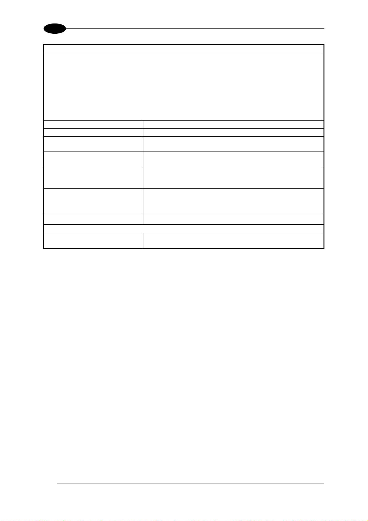
10
SOFTWARE FEATURES
READABLE CODES
* EAN/UPC (including Add-on 2 and Add-on 5) * Code 93
* 2/5 Interleav ed * Cod e 128
* Code 39 (Standard and Full ASCII) * EAN 128
* Codabar ISBT 128
*ABC Codabar Pharmacode
Plessey
*ACB Readable.
Code Selection
Decoding Safety
Headers and Terminators
Operating Modes
Configuration Modes
Genius™ based Host Mode Programming
Special Functions
Parameter Storage
USER INTERFACE
LED Indicators Ready, Good, Trigger, Com, Status, Power On
Multi-function Key X-PRESS™ button
up to ten different symbologies during one reading phase
can enable multiple good reads of same code
Up to 128-byte header string
Up to 128-byte terminator string
On-Line, Serial On-Line, Verifier,
Automatic, Continuous, Test
X-PRESS™ Functions
Genius™ utility program
ACB (Advanced Code Builder)
Motor Off and SW_Speed Control
Programmable Diagnostic and Statistic Messages
Non-volatile internal Flash
DS2100N REFERENCE MANUAL
Code Verifier
90
 Loading...