

ENGINEERING TOMORROW
Installation Guide
VLT® Parallel Drive Modules
250–1200 kW
vlt-drives.danfoss.com


Contents Installation Guide
Contents
1 Introduction
1.1 Purpose of the Manual
1.2 Additional Resources
1.3 Document and Software Version
1.4 Approvals and Certications
1.5 Disposal
2 Safety
2.1 Safety Symbols
2.2 Qualied Personnel
2.3 Safety Precautions
3 Product Overview
3.1 Intended Use
3.2 Drive Modules
3.3 Control Shelf
3.4 Wire Harness
3.5 DC Fuses
4
4
4
4
4
4
5
5
5
5
7
7
8
9
10
10
4 Mechanical Installation
4.1 Receiving and Unpacking the Unit
4.1.1 Items Supplied 11
4.1.2 Lifting the Unit 12
4.1.3 Storage 12
4.2 Requirements
4.2.1 Environmental 14
4.3 Installing the Drive Modules
4.4 Installing the Control Shelf
5 Electrical Installation
5.1 Safety Instructions
5.2 Electrical Requirements for Certications and Approvals
5.3 Wiring Diagram
5.4 Fuses
5.5 Electrical Kit Installation
5.6 DC Bus Fuse Installation
5.7 Motor Connections
11
11
14
16
18
19
19
20
21
22
24
24
24
5.7.3 Motor Terminal Connections 26
5.7.3.1 Motor Cable 26
5.7.3.2 Motor Terminal Connections in 2-Drive Module Systems 27
MG37K302 Danfoss A/S © 08/2017 All rights reserved. 1

Contents
VLT® Parallel Drive Modules
5.7.3.3 Motor Terminal Connections in 4-Drive Module Systems 27
5.8 Mains Connections
5.8.1 AC Mains Terminal Connections 28
5.8.1.1 Mains Terminal Connections in 2-Drive Module Systems 28
5.8.1.2 Mains Terminal Connections in 4-Drive Module Systems 29
5.8.2 12-Pulse Disconnector Conguration 29
5.8.3 Discharge Resistors 30
5.9 Control Shelf Installation
5.10 Control Wiring Connections
5.10.1 Control Cable Routing 32
5.10.2 Control Wiring 33
5.10.2.1 Control Terminal Types 33
5.10.2.2 Wiring to Control Terminals 35
5.10.2.3 Enabling Motor Operation (Terminal 27) 35
5.10.2.4 Voltage/Current Input Selection (Switches) 35
5.10.2.5 RS485 Serial Communication 36
5.10.3 Safe Torque O (STO) 36
5.11 Relay Output
28
31
31
36
5.12 EMC Recommendations
6 Initial Start-up
6.1 Pre-start Check List
6.2 Safety Instructions
6.3 Applying Power
6.4 Conguring the Drive System
6.5 Testing the Motor Operation
7 Specications
7.1 Power-dependent Specications
7.2 Mains Supply to Drive Module
7.3 Motor Output and Motor Data
7.4 12-Pulse Transformer Specications
7.5 Ambient Conditions for Drive Modules
7.6 Cable Specications
7.7 Control Input/Output and Control Data
7.8 Kit Dimensions
37
41
41
42
42
43
44
45
45
59
59
59
59
60
60
64
7.9 Fastener Tightening Torques
7.9.1 Tightening Torques for Terminals 66
8 Appendix
8.1 Disclaimer
2 Danfoss A/S © 08/2017 All rights reserved. MG37K302
66
67
67

Contents Installation Guide
8.2 Symbols, Abbreviations, and Conventions
8.3 Block Diagrams
Index
67
68
79
MG37K302 Danfoss A/S © 08/2017 All rights reserved. 3
Introduction
VLT® Parallel Drive Modules
11
1 Introduction
1.1 Purpose of the Manual
This manual provides requirements for mechanical and
electrical installation of the VLT® Parallel Drive Modules
basic kit. Separate installation instructions for optional
components - bus bars and back-channel cooling - are
provided with those kits.
This guide includes information on:
Wiring of mains and motor connections.
•
Wiring of control and serial communications.
•
Control terminal functions.
•
Detailed tests that must be performed before
•
start-up.
Initial programming to verify proper functioning
•
of the drive system.
The installation guide is intended for use by
personnel.
To install the drive modules and paralleling kit safely and
professionally, read and follow the installation guide. Pay
particular attention to the safety instructions and general
warnings. Always keep this installation guide with the
panel containing the VLT® Parallel Drive Modules
components.
VLT® is a registered trademark.
Additional Resources
1.2
Other resources are available to understand functions and
programming of the VLT® Parallel Drive Modules.
qualied
The VLT® FC Series, D-frame Service Manual
•
contains detailed service information, including
information applicable to the VLT® Parallel Drive
Modules.
The VLT® Parallel Drive Modules DC Fuses Instal-
•
lation Instructions contain detailed information
about installing the DC fuses.
®
The VLT
•
lation Instructions contain detailed information
about installing the bus bar kit.
The VLT® Parallel Drive Modules Duct Kit Instal-
•
lation Instructions contain detailed information
about installing the duct kit.
Refer to other supplemental publications and manuals,
available from Danfoss. See drives.danfoss.com/knowledge-
center/technical-documentation/ for listings.
Parallel Drive Modules Bus Bar Kit Instal-
1.3 Document and Software Version
This manual is regularly reviewed and updated. All
suggestions for improvement are welcome. Table 1.1 shows
the document version and the corresponding software
version.
Edition Remarks Software
version
MG37K3xx Added 230 V external
power supply content
Table 1.1 Document and Software Version
Approvals and Certications
1.4
FC 102 (5.0x),
FC 202 (3.0x),
FC 302 (7.6x)
The VLT® Parallel Drive Modules Design Guide
•
contains detailed information about the
capabilities and functionality of motor control
systems using these drive modules, and provides
guidance for designing this type of system.
The VLT® Parallel Drive Modules User Guide
•
contains detailed procedures for start-up, basic
operational programming, and functional testing.
Additional information describes the user
interface, application examples, troubleshooting,
and specications.
Refer to the Programming Guide applicable to the
•
particular series of VLT® Parallel Drive Modules
used in creating the drive system. The
programming guide describes in greater detail
how to work with parameters and provides
application examples.
4 Danfoss A/S © 08/2017 All rights reserved. MG37K302
Table 1.2 Approvals and Certications
Disposal
1.5
Do not dispose of equipment containing
electrical components together with
domestic waste.
Collect it separately in accordance with
local and currently valid legislation.
Safety Installation Guide
2 Safety
2.1 Safety Symbols
The following symbols are used in this manual:
WARNING
Indicates a potentially hazardous situation that could
result in death or serious injury.
CAUTION
Indicates a potentially hazardous situation that could
result in minor or moderate injury. It can also be used to
alert against unsafe practices.
NOTICE
Indicates important information, including situations that
can result in damage to equipment or property.
WARNING
UNINTENDED START
When the drive system is connected to AC mains, the
motor can start at any time. Unintended start during
programming, service, or repair work can result in death,
serious injury, or property damage. The motor can start
via an external switch, a eldbus command, an input
reference signal from the LCP, a cleared fault condition,
or remote operation using MCT 10 Set-up Software.
To prevent unintended motor start:
Disconnect the drive system from AC mains.
•
Press [O/Reset] on the LCP, before
•
programming parameters.
The drive system, motor, and any driven
•
equipment must be fully wired and assembled
when the drive is connected to AC mains.
2 2
2.2 Qualied Personnel
Correct and reliable transport, storage, and installation are
required for the trouble-free and safe operation of the
VLT® Parallel Drive Modules. Only qualied personnel are
allowed to install this equipment.
Qualied personnel are dened as trained sta, who are
authorized to install equipment, systems, and circuits in
accordance with pertinent laws and regulations. Also, the
personnel must be familiar with the instructions and safety
measures described in this manual.
Safety Precautions
2.3
WARNING
HIGH VOLTAGE
The drive system contains high voltage when connected
to AC mains input. Failure to ensure that only qualied
personnel install the drive system can result in death or
serious injury.
Only qualied personnel are allowed to install the
•
drive system.
CAUTION
POTENTIAL HAZARD IN THE EVENT OF
INTERNAL FAILURE
There is a risk of personal injury when the drive modules
are not properly closed.
Before applying power, ensure that all safety
•
covers are in place and securely fastened.
WARNING
DISCHARGE TIME
The drive module contains DC-link capacitors. Once
mains power has been applied to the drive, these
capacitors can remain charged even after the power has
been removed. High voltage can be present even when
the warning indicator lights are o. Failure to wait 20
minutes after power has been removed before
performing service or repair work can result in death or
serious injury.
1. Stop the motor.
2. Disconnect AC mains and remote DC-link
supplies, including battery back-ups, UPS, and
DC-link connections to other drives.
3. Disconnect or lock the PM motor.
4. Wait 20 minutes for the capacitors to discharge
fully before performing any service or repair
work.
WARNING
UNINTENDED MOTOR ROTATION
WINDMILLING
Unintended rotation of permanent magnet motors
creates voltage and can charge the capacitors in the
drive system, resulting in death, serious injury, or
equipment damage.
Ensure that permanent magnet motors are
•
blocked to prevent unintended rotation.
MG37K302 Danfoss A/S © 08/2017 All rights reserved. 5
Safety
VLT® Parallel Drive Modules
WARNING
LEAKAGE CURRENT HAZARD (>3.5 mA)
22
Leakage currents exceed 3.5 mA. Failure to ground the
drive system properly can result in death or serious
injury. Follow national and local codes regarding
protective earthing of equipment with a leakage current
>3.5 mA. Frequency converter technology implies high
frequency switching at high power. This switching
generates a leakage current in the ground connection. A
fault current in the drive system at the output power
terminals sometimes contain a DC component, which can
charge the lter capacitors and cause a transient ground
current. The ground leakage current depends on various
system congurations including RFI ltering, shielded
motor cables, and drive system power.
If the leakage current exceeds 3.5 mA, EN/IEC 61800-5-1
(Power Drive System Product Standard) requires special
care.
Grounding must be reinforced in 1 of the following ways:
Ensure the correct grounding of the equipment
•
by a certied electrical installer.
Ground wire of at least 10 mm2 (6 AWG).
•
Two separate ground wires, both complying
•
with the dimensioning rules.
See EN 60364-5-54 § 543.7 for further information.
WARNING
HEAVY LOAD
Unbalanced loads can fall and loads can tip over. Failure
to take proper lifting precautions increases risk of death,
serious injury, or equipment damage.
Never walk under suspended loads.
•
To guard against injury, wear personal
•
protective equipment such as gloves, safety
glasses, and safety shoes.
Be sure to use lifting devices with the
•
appropriate weight rating. The lifting bar must
be able to handle the weight of the load.
The load’s center of gravity may be in an
•
unexpected location. Failure to locate the center
of gravity correctly, and position the load
accordingly before lifting the load, can cause
the unit to fall over or tilt unexpectedly during
lifting and transport.
The angle from the top of the drive module to
•
the lifting cables has an impact on the
maximum load force on the cable. This angle
must be 65° or greater. Attach and dimension
the lifting cables properly.
WARNING
EQUIPMENT HAZARD
Contact with rotating shafts and electrical equipment
can result in death or serious injury.
Ensure that only trained and qualied personnel
•
perform the installation.
Ensure that electrical work conforms to national
•
and local electrical codes.
Follow the procedures in this document.
•
WARNING
DISCONNECT POWER BEFORE SERVICING
Sometimes during installation, AC mains power is
applied but then must be disconnected to change the
line connections. Failure to follow these steps can result
in death or serious injury.
Disconnect the frequency converters from the
•
AC mains, 230 V supply, and motor lines.
After the lines have been disconnected, wait 20
•
minutes for the capacitors to discharge.
6 Danfoss A/S © 08/2017 All rights reserved. MG37K302

Product Overview Installation Guide
3 Product Overview
3.1 Intended Use
A frequency converter is an electronic motor controller that uses 1 or more drive modules to convert AC mains input into a
variable AC waveform output. The frequency and voltage of the output are regulated to control the motor speed or torque.
The frequency converter varies the motor speed based on system feedback, such as position sensors on a conveyor belt.
The frequency converter also regulates the motor in response to remote commands from external controllers.
The VLT® Parallel Drive Modules basic kit described in this guide is UL 508 C compliant. The kit is used to create drive
systems of 2 or 4 drive modules. These drive modules are based on the D4h frequency converter and can provide a greater
power range in a smaller enclosure. The basic kit is designed to allow the exibility to either order components through
Danfoss or fabricate custom components.
The basic kit contains the following components:
Drive modules
•
Control shelf
•
Wire harnesses
•
- Ribbon cable with 44-pin connector (on both ends of the cable)
- Relay cable with 16-pin connector (on 1 end of the cable)
- DC fuse microswitch cable with 2-pin connectors (on 1 end of the cable)
DC fuses
•
Microswitches
•
Other components, such as bus bar kits and back-channel cooling duct kits, are available as options to customize the drive
system.
3 3
NOTICE
EXTERNAL 230 V SUPPLY
An external 230 V supply is needed to power the SMPS
(switch mode power supply) and any cabinet fans.
MG37K302 Danfoss A/S © 08/2017 All rights reserved. 7
130BE561.11
2
3
4
1
5
6
7
8
9
12
13
11
10
Product Overview
VLT® Parallel Drive Modules
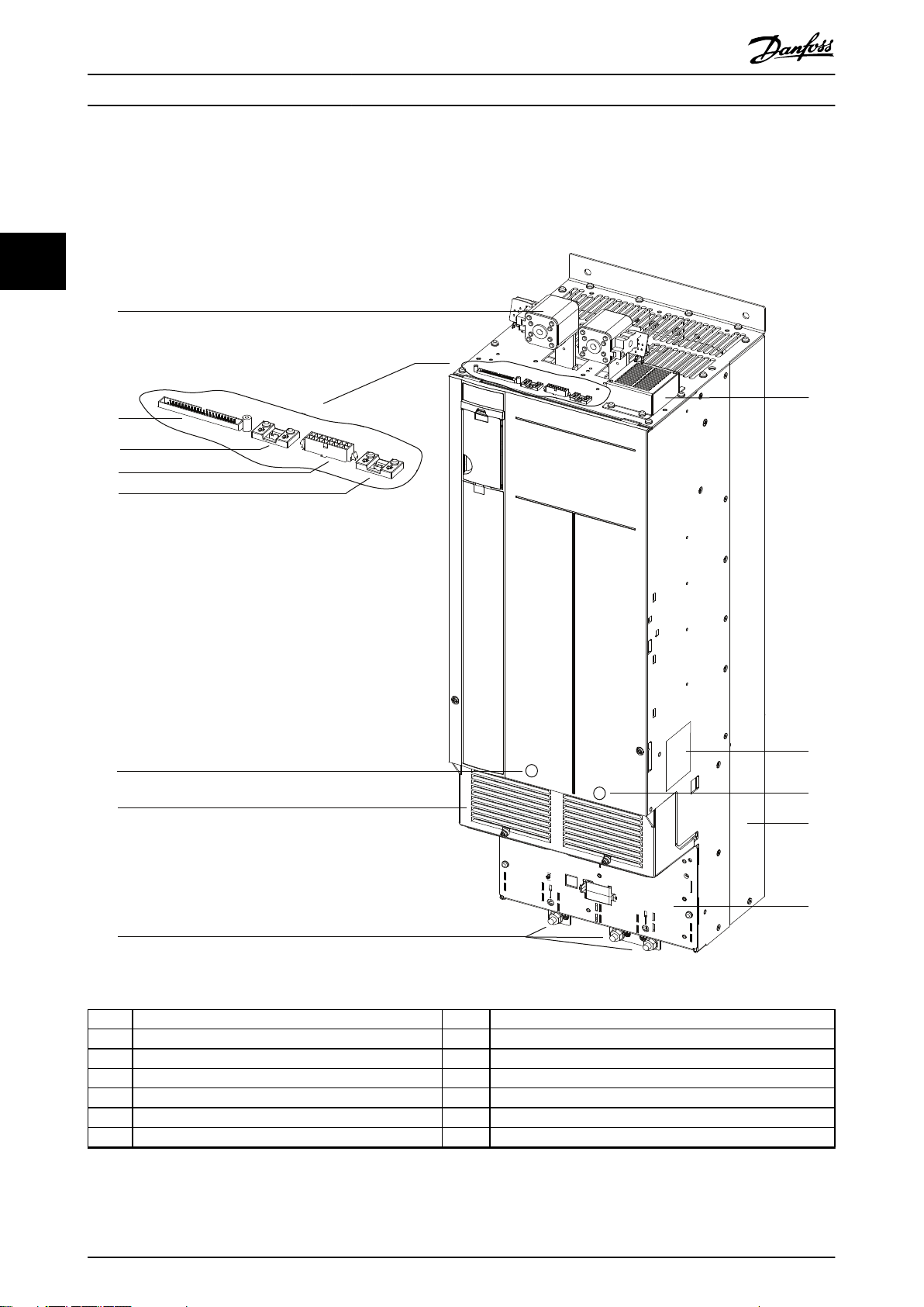
3.2 Drive Modules
Each drive module has an IP00 protection rating. Either 2 or 4 drive modules can be connected in parallel to create a drive
system, based on power requirements.
33
1 DC-link terminal and DC fuse 8 Ground terminals
2 MDCIC plug 9 Top fan
3 Microswitch to DC fuse 10 Drive module label. See Illustration 4.2.
4 Relays 1 and 2 11 Motor output terminals (inside the unit)
5 Brake fault jumper and connector 12 Heat sink and heat sink fan
6 Mains input terminals (inside the unit) 13 Ground plate
7 Terminal cover – –
Illustration 3.1 Drive Module Overview
8 Danfoss A/S © 08/2017 All rights reserved. MG37K302
130BE597.11
1
2
3
5
7
8
4
9
11
6
10
12
Product Overview Installation Guide
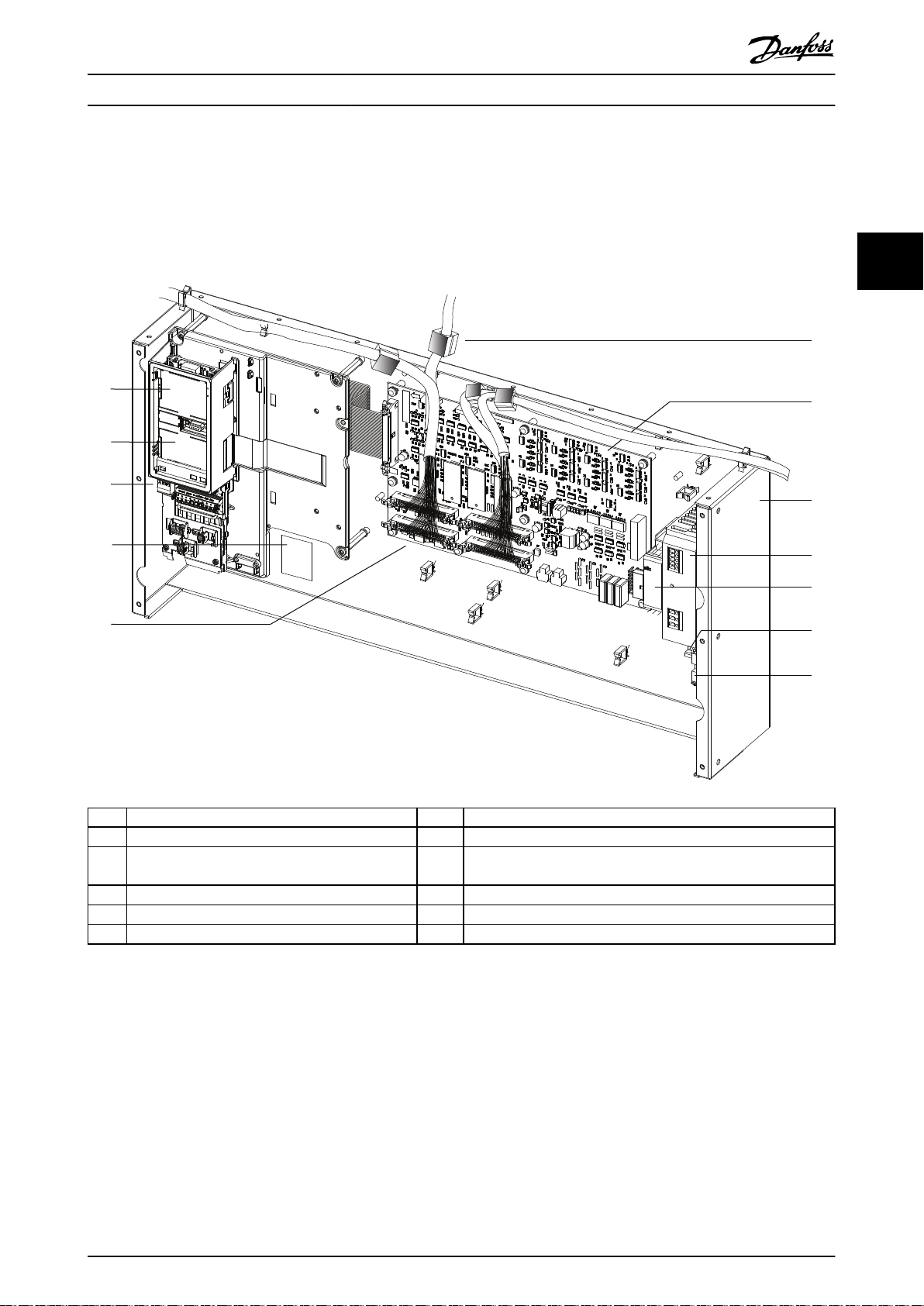
3.3 Control Shelf
The control shelf contains the LCP, MDCIC, and control card. The LCP provides access to the system parameters. The MDCIC
is connected to each of the drive modules via a ribbon cable and communicates to the control card. The control card
controls the operation of the drive modules.
3 3
1 LCP cradle 7 MDCIC card
2 Control card (underneath cover) 8 Control shelf
3 Control terminal blocks 9 Switch mode power supply (SMPS). Note that an external 230 V
supply is needed to power the SMPS.
4 Top-level drive system label. See Illustration 4.1. 10 Pilz relay
5 44-pin cables from MDCIC board to drive modules 11 DIN rail
6 Ferrite core 12 Terminal block mounted on DIN rail
Illustration 3.2 Control Shelf
MG37K302 Danfoss A/S © 08/2017 All rights reserved. 9
130BE750.10
1
2
Product Overview
VLT® Parallel Drive Modules
3.4 Wire Harness
The VLT® Parallel Drive Modules basic kit contains the following wire harnesses:
Ribbon cable with 44-pin connector (on both ends of the cable)
•
Relay cable with 16-pin connector (on 1 end of the cable)
•
DC fuse microswitch cable with 2-pin connectors (on 1 end of the cable)
33
•
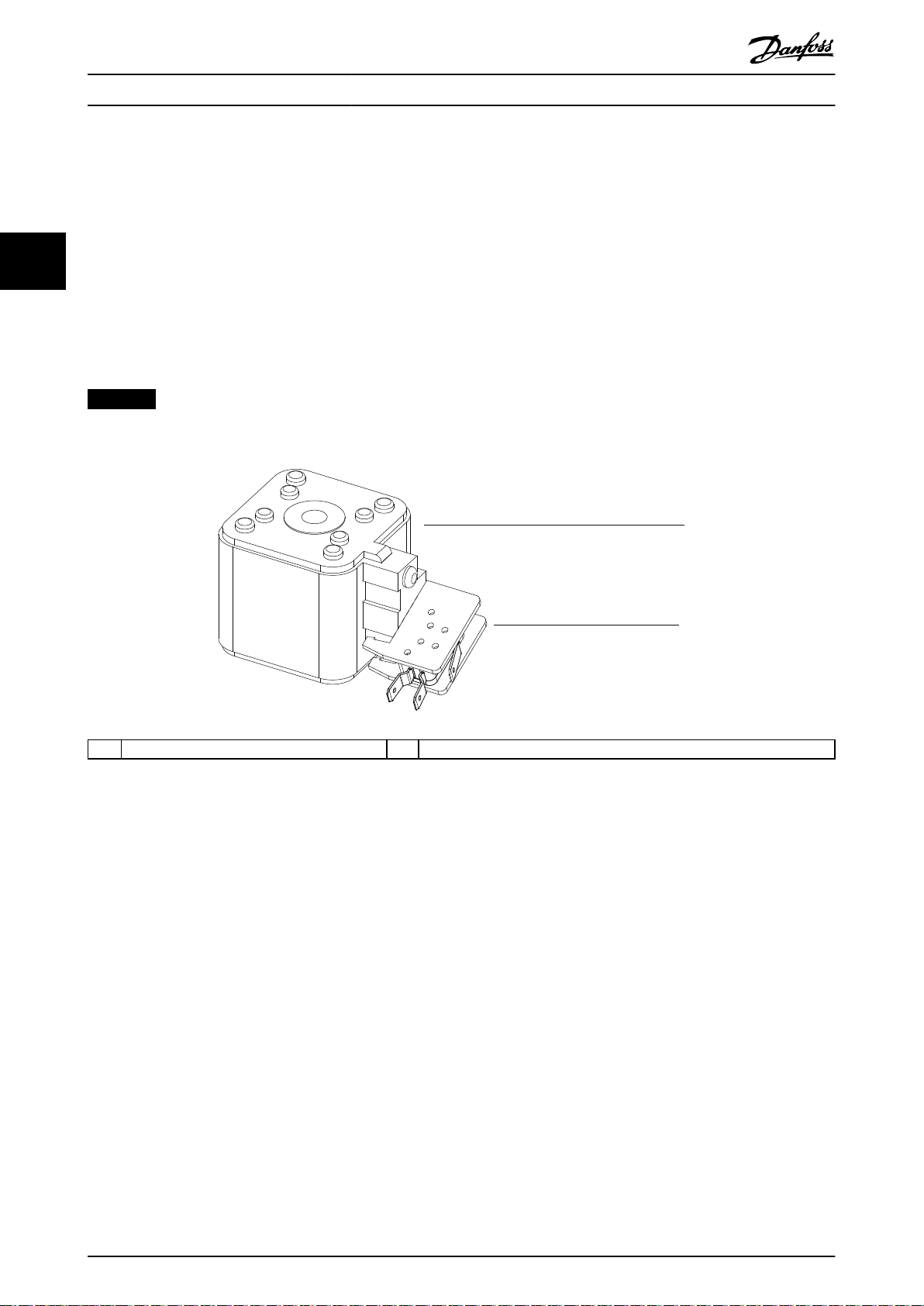
3.5 DC Fuses
The VLT® Parallel Drive Modules kit contains 2 DC fuses per drive module. These fuses on the supply side ensure that any
damage is contained to inside the drive modules.
NOTICE
Use of fuses on the supply side is mandatory for IEC 60364 (CE) compliant installations.
1 DC fuse 2 Microswitch connector
Illustration 3.3 DC Fuse and Microswitch Connector
10 Danfoss A/S © 08/2017 All rights reserved. MG37K302
130BE710.12
OUT: 3x0-Vin 0-590Hz 1260/1160 A
IN: 3x380-500V 50/60Hz 1227/1129 A
710 kW / 1000 HP, High Overload
OUT: 3x0-Vin 0-590Hz 1460/1380 A
IN: 3x380-500V 50/60Hz 1422/1344 A
800 kW / 1200 HP, Normal Overload
VLT
T/C: FC-302N710T5E00P2BGC7XXSXXXXAXBXCXXXXDX
P/N: 134X4109 S/N:
R
AutomationDrive
www.danfoss.com
1
2
3
4
5
6
ASSEMBLED IN USA
CAUTION - ATTENTION:
Stored charge, wait 20 min.
Charge residuelle, attendez 20
See manual for special condition / prefuses
Voir manuel de conditions speciales / fusibles
WARNING - AVERTISSEMENT:
`
`
Tamb. 45
˚
C/113
˚
F at Full Output Current
CHASSIS (OPEN TYPE) / IP00
SCCR 100 kA at UL Voltage range 380-500 V
Listed 36U0 E70524 IND. CONT. EQ.
UL Voltage range 380-500 V
Max. Tamb. 55
˚
C/131
˚
F w/ Output Current Derating
123456H123
130BE711.14
Intended use - The Individual Base Drive
Modules are intended for use in Parallel Drive
Module system only. Specic electrical
ratings are not applicable. Name plate of
Parallel Drive Module system should
be referred for actual drive ratings.
VLT
ASSEMBLED IN USA
T/C: FC-BDMN250T5E00H2SXC7XXSXXXXAXBXCXXXXDX
P/N: 178N0025 S/N: 123456H123
CAUTION - ATTENTION:
Stored charge, wait 20 min.
Charge residuelle, attendez 20
See manual for special condition / prefuses
Voir manuel de conditions speciales / fusibles
WARNING - AVERTISSEMENT:
R
AutomationDrive
www.danfoss.com
`
`
CHASSIS (OPEN TYPE) / IP00
SCCR 100 kA at UL Voltage range 380-500 V
Listed 36U0 E70524 IND. CONT. EQ.
1
2
3
4
5
UL Voltage range 380-500 V
Mechanical Installation Installation Guide
4 Mechanical Installation
4.1 Receiving and Unpacking the Unit
4.1.1 Items Supplied
Make sure that the items supplied and the
•
information on the labels correspond to the
order.
- Top-level drive system. This label is
found on the control shelf, lower right
side of the LCP. See Illustration 3.2.
- Drive module. This label is found inside
the drive module enclosure, on the right
side panel. See Illustration 3.1.
Visually check the packaging and the VLT
•
Parallel Drive Modules components for damage
caused by inappropriate handling during
shipment. File any claim for damage with the
carrier. Retain damaged parts, in case
is needed.
®
clarication
4 4
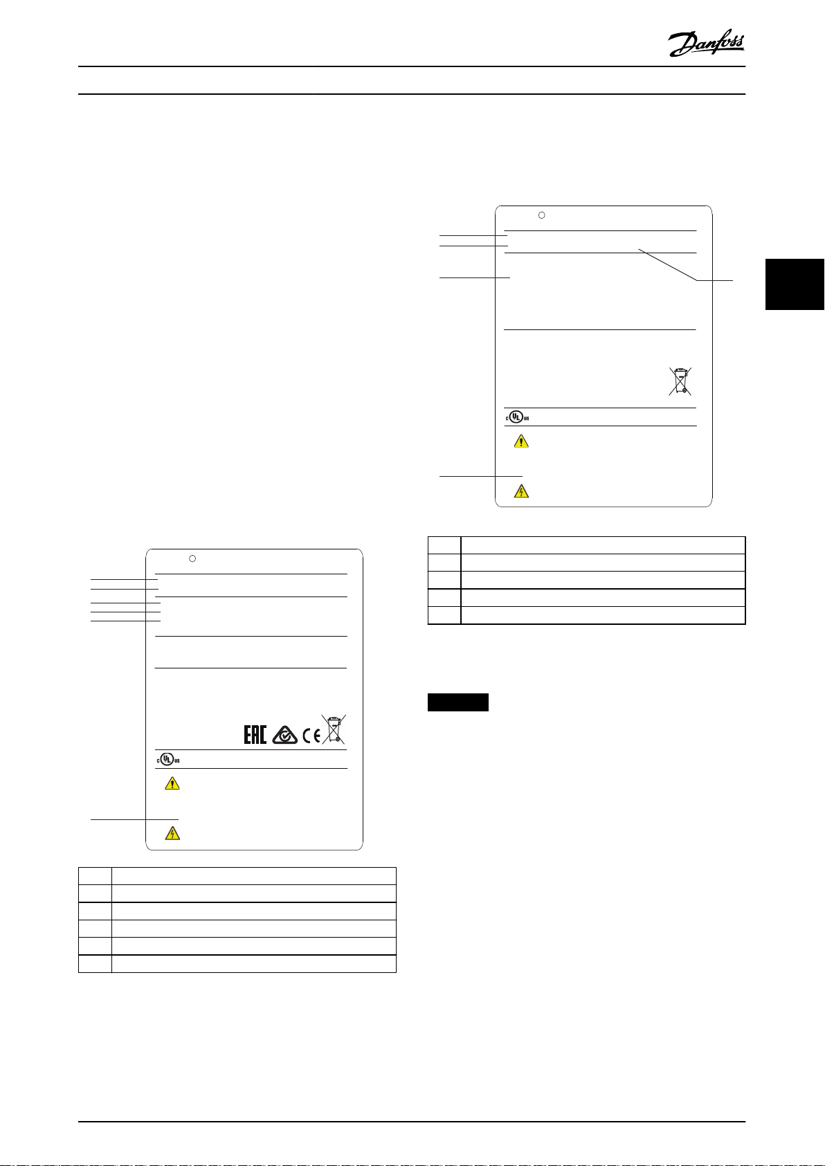
1 Type code
2 Code number
3 Intended use disclaimer
4 Discharge time
5 Serial number
Illustration 4.2 Drive Module Label (Example)
NOTICE
LOSS OF WARRANTY
Removing the labels from the VLT® Parallel Drive
Modules can result in loss of warranty.
1 Type code
2 Code number
3 Power rating
4 Input voltage, frequency, and current
5 Output voltage, frequency, and current
6 Discharge time
Illustration 4.1 Top-level Drive System Label (Example)
MG37K302 Danfoss A/S © 08/2017 All rights reserved. 11

Mechanical Installation
Receiving and unloading
I-beam and hooks rated to lift a drive module having a weight of 125 kg (275 lb), with the necessary safety
•
margins.
Crane or other lifting aid rated to lift the minimum weight specied in the documentation package supplied with
•
the drive module.
Crowbar to disassemble the wooden shipping container.
•
Installation
Drill with 10 mm or 12 mm drill bits.
44
•
Tape measurer.
•
Screwdriver.
•
Wrench with relevant metric sockets (7–17 mm).
•
Wrench extensions.
•
Torx T50 tool.
•
Cabinet construction
Acquire the tools necessary for assembly of the panel - according to the design plans and established practices.
VLT® Parallel Drive Modules
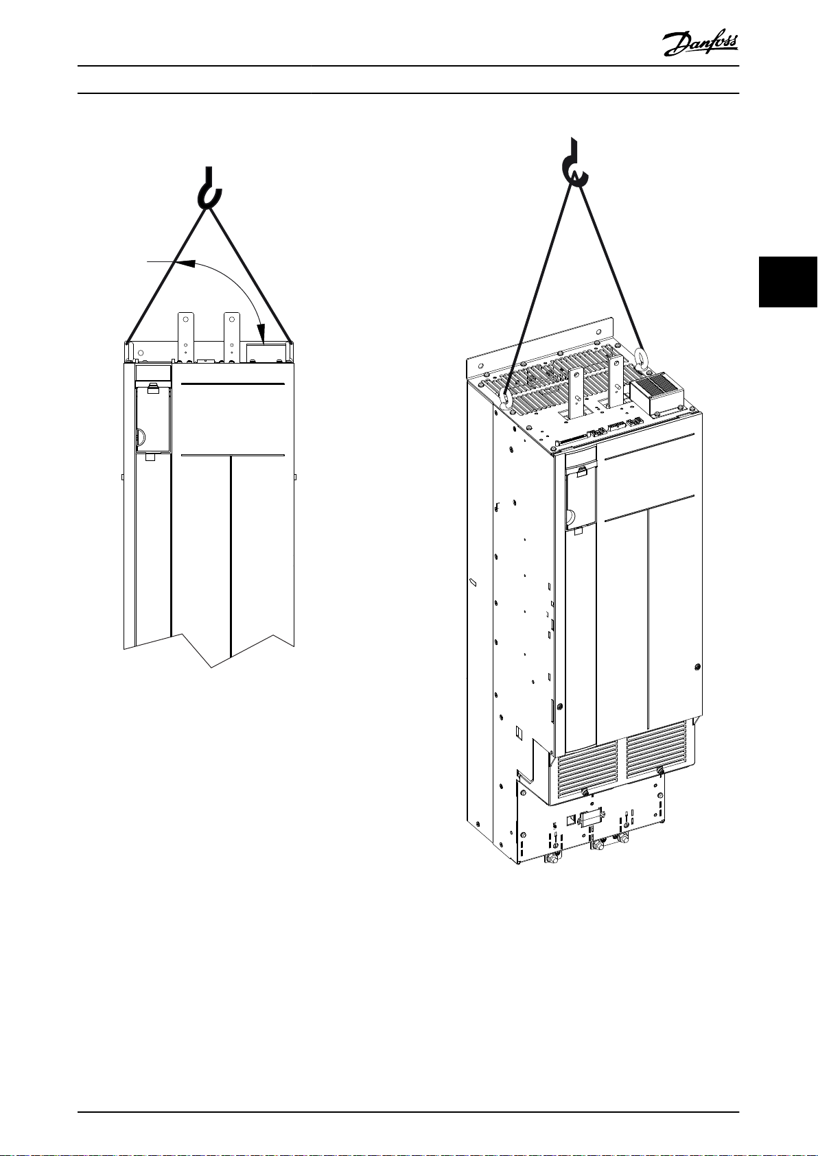
4.1.2 Lifting the Unit
For measurements and center of gravity, see chapter 7.8 Kit Dimensions.
Ensure that the lifting device is suitable for the task.
•
Move the unit using a hoist, crane, or forklift with the appropriate rating.
•
Always use the dedicated lifting eye bolts. See Illustration 4.3.
•
CAUTION
HEAVY LOAD
Unbalanced loads can fall and loads can tip over. Failure to take proper lifting precautions increases risk of death,
serious injury, or equipment damage.
Never walk under suspended loads.
•
To guard against injury, wear personal protective equipment such as gloves, safety glasses, and safety shoes.
•
Be sure to use lifting devices with the appropriate weight rating. The lifting bar must be able to handle the
•
weight of the load.
The load’s center of gravity may be in an unexpected location. Failure to locate the center of gravity correctly
•
and position the load accordingly before lifting the load can cause the unit to fall over or tilt unexpectedly
during lifting and transport.
The angle from the top of the drive module to the lifting cables has an impact on the maximum load force on
•
the cable. This angle must be 65° or greater. Refer to Illustration 4.3. Attach and dimension the lifting cables
properly.
4.1.3 Storage
Store the kit in a dry location. Keep the equipment sealed in its packaging until installation. Refer to chapter 7.5 Ambient
Conditions for Drive Modules for recommended ambient conditions.
12 Danfoss A/S © 08/2017 All rights reserved. MG37K302
130BE566.10
65° min
Mechanical Installation Installation Guide
4 4
Illustration 4.3 Lifting the Drive Module
MG37K302 Danfoss A/S © 08/2017 All rights reserved. 13
Mechanical Installation
VLT® Parallel Drive Modules
4.2 Requirements
This section describes the minimum recommended
requirements for mechanical installation. For UL and CE
requirements, see chapter 5.2 Electrical Requirements for
Certications and Approvals.
4.2.3 Busbars
If the Danfoss busbar kit is not used, see Table 4.2 for the
cross-section measurements that are required when
creating customized busbars. For terminal dimensions, refer
to chapter 7.8.2 Terminal Dimensions and chapter 7.8.3 DC
Bus Dimensions.
4.2.1 Environmental
44
Refer to for information on required operating
temperature, humidity, and other environmental
conditions.
4.2.2 Cabinet
The kit consists of either 2 or 4 drive modules, depending
on the power rating. The cabinets have to meet the
following minimum requirements:
Description Width [mm (in)] Thickness [mm (in)]
AC motor 143.6 (5.7) 6.4 (0.25)
AC mains 143.6 (5.7) 6.4 (0.25)
DC bus 76.2 (3.0) 12.7 (0.50)
Table 4.2 Cross-section Measurements for Customized Busbars
NOTICE
Align busbars vertically to provide maximum airow.
4.2.4 Thermal Considerations
Width [mm (in)] 2-drive: 800 (31.5), 4-drive: 1600 (63)
Depth [mm (in)] 600 (23.6)
Height [mm (in)]
Weight capacity
[kg (lb)]
Ventilation openings See chapter 4.2.5 Cooling and Airow
Table 4.1 Cabinet Requirements
1) Required if Danfoss busbar or cooling kits are used.
2000 (78.7)
2-drive: 450 (992), 4-drive: 910 (2006)
Requirements.
1)
NOTICE
EXTERNAL 230 V SUPPLY
An external 230 V supply is required for the SMPS
(switch mode power supply). Danfoss recommends using
a 6 A, 10 A, or 16 A slow-blow fuse when installing the
external supply.
For heat dissipation values, refer to chapter 7.1 Powerdependent Specications. The following heat sources must
be considered when determining cooling requirements:
Ambient temperature outside enclosure.
•
Filters (for example, sine-wave and RF).
•
Fuses.
•
Control components.
•
For required cooling air, refer to chapter 4.2.5 Cooling and
Airow Requirements.
14 Danfoss A/S © 08/2017 All rights reserved. MG37K302
130BE569.10
Mechanical Installation Installation Guide
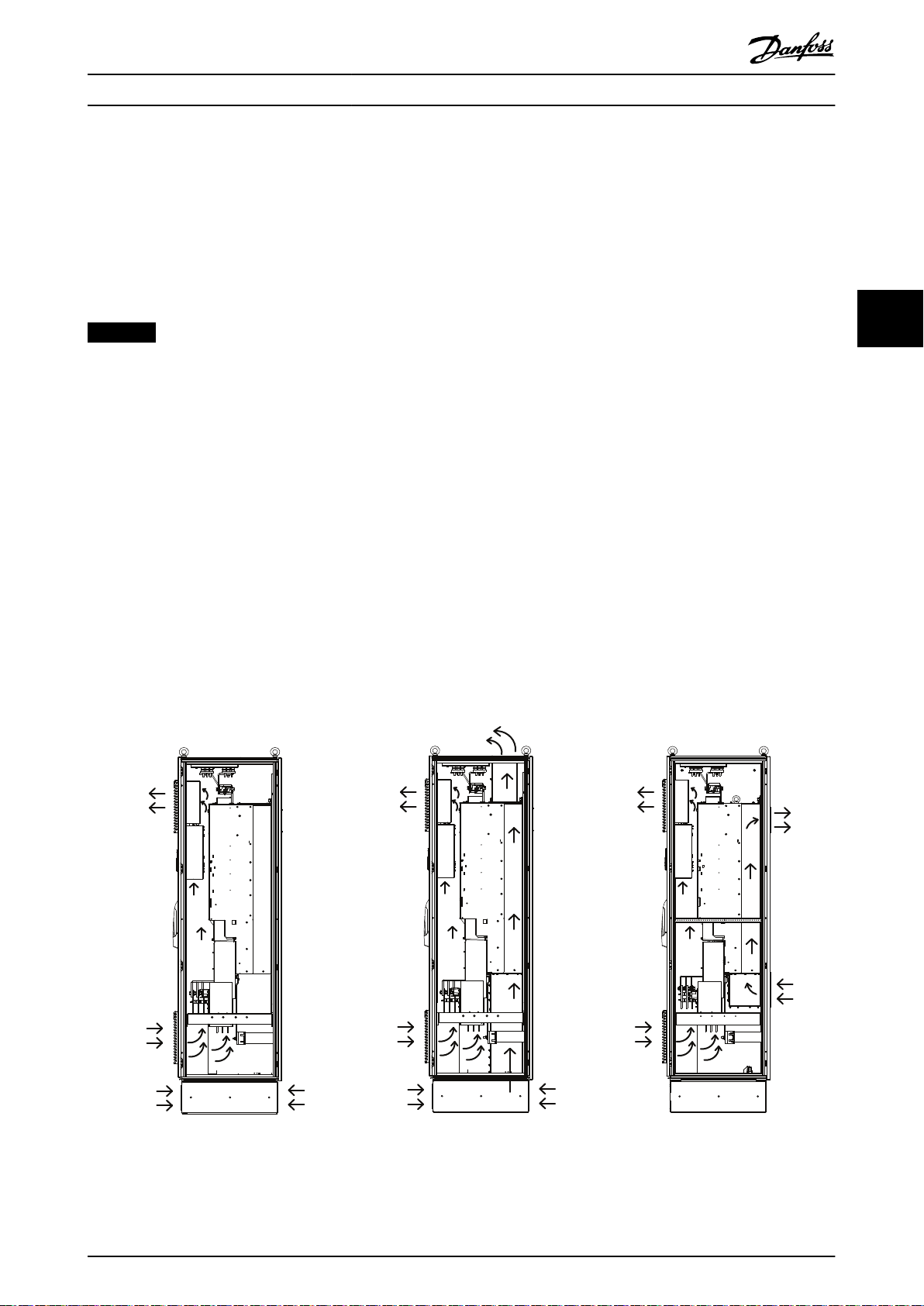
4.2.5 Cooling and Airow Requirements
The recommendations provided in this section are necessary for eective cooling of the drive modules within the panel
enclosure. Each drive module contains a heat sink fan and a mixing fan. Typical enclosure designs utilize door fans along
with the drive module fans to remove waste heat from the enclosure.
Danfoss provides several back-channel cooling kits as options. These kits remove 85% of the waste heat from the enclosure,
reducing the need for large door fans.
NOTICE
Make sure that the total ow of the cabinet fans meets the recommended airow.
Drive module cooling fans
The drive module is equipped with a heat sink fan, which provides the required
heat sink. Also, there is a cooling fan mounted on the top of the unit, and a small 24 V DC mixing fan mounted under the
input plate that operates any time the drive module is powered on.
In each drive module, the power card provides DC voltage to power the fans. The mixing fan is powered by 24 V DC from
the main switch mode power supply. The heat sink fan and the top fan are powered by 48 V DC from a dedicated switch
mode power supply on the power card. Each fan has a tachometer feedback to the control card to conrm that the fan is
operating correctly. On/o and speed control of the fans help reduce unnecessary acoustical noise and extend the life of the
fans.
Cabinet fans
When the back-channel option is not used, fans mounted in the cabinet must remove all the heat generated inside the
enclosure.
For each enclosure housing 2 drive module, the cabinet fan ow recommendation is as follows:
When back-channel cooling is used, 680 m3/h (400 cfm) ow is recommended.
•
When back-channel cooling is not used, 4080 m3/h (2400 cfm) ow is recommended.
•
ow rate of 840 m3/h (500 cfm) across the
4 4
Illustration 4.4 Airow, Standard Unit (Left), Bottom/Top Cooling Kit (Middle), and Back/Back Cooling Kit (Right)
MG37K302 Danfoss A/S © 08/2017 All rights reserved. 15
130BE571.10
Mechanical Installation
VLT® Parallel Drive Modules
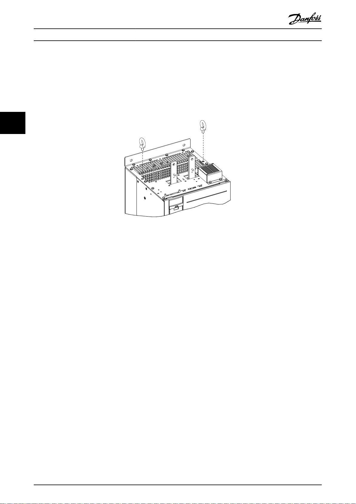
4.3 Installing the Drive Modules
Install the drive modules into the cabinet frame as described in the following steps.
1. Unpack the drive modules from the packaging. See chapter 4.1 Receiving and Unpacking the Unit.
2. Install 2 eye bolts in the top of the
lifting harness and an overhead hoist or crane with the necessary lifting capacity. See chapter 4.1.2 Lifting the Unit.
rst drive module. Prepare the drive module for lifting, using an appropriate
44
Illustration 4.5 Installation of Eye Bolts
3. Install the 2 bottom mounting screws and gaskets onto the mounting panel.
4. Using the crane or hoist, lift the drive module and then lower the unit through the top of the cabinet frame. Align
the bottom mounting holes of the unit with the 2 bottom mounting screws on the mounting panel.
5. Verify that the drive module is correctly aligned on the mounting panel and then secure the bottom of the unit to
the panel with the 2 hex nuts. See Illustration 4.6. Torque the hex nuts. Refer to chapter 7.9 Fastener Tightening
Torques.
6. Secure the top of the unit to the mounting panel with M10x26 screws, and then torque the screws.
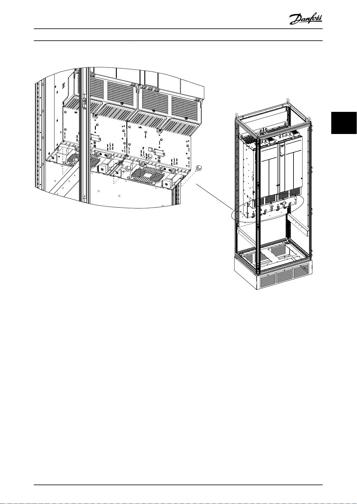
7. Line up the groove on the microswitch with the edges on each DC fuse and press rmly until the microswitch
clicks into place.
8. Install 2 DC fuses with microswitches onto the tops of the DC-link terminals on each drive module. The
microswitches should be installed on the outer side of each terminal. Refer to Illustration 3.1.
9. Secure each fuse with 2 M10 screws and torque the screws.
10. Install the next drive module.
16 Danfoss A/S © 08/2017 All rights reserved. MG37K302
130BE572.10
Mechanical Installation Installation Guide
4 4
Illustration 4.6 Installation of Bottom Mounting Bolts
MG37K302 Danfoss A/S © 08/2017 All rights reserved. 17
130BE713.11
1
2
Mechanical Installation
VLT® Parallel Drive Modules
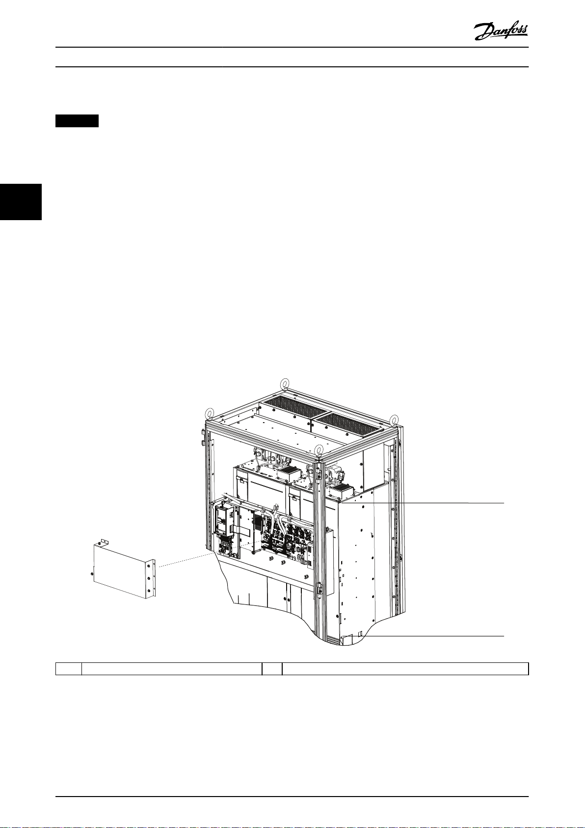
4.4 Installing the Control Shelf
NOTICE
To avoid RFI, do not route control wiring together with power cables or bus bars.
1. Remove the control shelf assembly from its package.
2. Remove the LCP from the control shelf.
3. Use some type of mounting bracket to install the control shelf. Danfoss does not supply the mounting brackets for
44
the control shelf. For EMC-correct installation, refer to Illustration 4.7.
4. Remove the MDCIC cover from the control shelf assembly.
5. Connect the 44-pin ribbon cables from the MDCIC card to the top of the drive modules, following the sequence
numbers indicated next to the connectors on the MDCIC.
6. Route the 44-pin ribbon cables inside the cabinet.
7. Connect the external brake fault wiring harness between the microswitch terminals and the brake jumper
connector on the top of the drive module.
8. Connect the relay wiring between relay 1 or 2 on the control shelf and the corresponding relay connector on the
top of the drive module.
9. Connect the microswitch to the microswitch connector provided on the top of the drive module. Refer to
Illustration 3.1 and Illustration 3.3.
1 Control shelf must stay below this point 2 Control shelf must stay above this point
Illustration 4.7 Positioning the Control Shelf for EMC-correct Installation
18 Danfoss A/S © 08/2017 All rights reserved. MG37K302
Electrical Installation Installation Guide
5 Electrical Installation
5.1 Safety Instructions
See chapter 2 Safety for general safety instructions.
WARNING
INDUCED VOLTAGE
When output motor cables from dierent frequency
converters are run together, induced voltage can charge
equipment capacitors even with the equipment turned
o and locked out.
To avoid death or serious injury:
Run output motor cables separately or use
•
shielded cables.
Simultaneously lock out all the frequency
•
converters.
CAUTION
SHOCK HAZARD
The drive system can cause a DC current in the
protective earth (PE) conductor.
When a residual current-operated protective
•
device (RCD) is used for protection against
electrical shock, only an RCD of Type B is
allowed on the supply side.
Failure to follow this recommendation could prevent the
RCD from providing the intended protection.
NOTICE
MOTOR OVERLOAD PROTECTION
The drive modules are supplied with Class 20 overload
protection for single motor applications.
Overcurrent protection
Extra protective equipment, such as short-circuit
•
protection or motor thermal protection between
the drive modules and the motors, is required for
applications with multiple motors.
The correct input fusing is required to acquire
•
approvals and meet certication requirements,
and to provide short circuit and overcurrent
protection. These fuses are not factory-supplied,
and must be provided by the installer. See
maximum fuse ratings in chapter 7.1 Power-
dependent Specications.
Wire type and ratings
All wiring must comply with local and national
•
regulations regarding cross-section and ambient
temperature requirements.
Power connection wire recommendation:
•
minimum 75 °C rated copper wire.
See chapter 7.6 Cable Specications for recommended wire
sizes and types.
5 5
CAUTION
PROPERTY DAMAGE
Electronic thermal relay (ETR) protection against motor
overload is not included in the default setting. To
program the LCP for this function, refer to the VLT
Parallel Drive Modules User Guide.
®
MG37K302 Danfoss A/S © 08/2017 All rights reserved. 19

Electrical Installation
VLT® Parallel Drive Modules
5.2 Electrical Requirements for Certications and Approvals
The standard conguration provided in this guide (drive
modules, control shelf, wire harnesses, fuses, and
microswitches) is UL and CE certied. The following
conditions must be met apart from the standard congu-
ration to obtain UL and CE regulatory approval
requirements. For a list of disclaimers, see
chapter 8.1 Disclaimer.
Use the frequency converter in a heated, indoor-
•
controlled environment. Cooling air must be
55
clean, free from corrosive materials, and
electrically conductive dust. See for specic limits.
Maximum ambient air temperature is 40 °C
•
(104 °F) at rated current.
The drive system must be assembled in clean air,
•
according to enclosure classication. To obtain UL
or CE certication regulatory approvals, drive
modules must be installed according to the
standard conguration provided in this guide.
Maximum voltage and current must not exceed
•
the values provided in chapter 7.1 Powerdependent
conguration.
The drive modules are suitable for use on a
•
circuit capable of delivering not more than
100 kA rms symmetrical amperes at the drive
Specications for the specied drive
nominal voltage (600 V maximum for 690 V units)
when protected by fuses with the standard
conguration. Refer to chapter 5.4.1 Fuse Selection.
The ampere rating is based on tests done
according to UL 508C.
The cables located within the motor circuit must
•
be rated for at least 75 °C (167 °F) in ULcompliant installations. The cable sizes have been
provided in chapter 7.1 Power-dependent Speci-
cations for the specied drive conguration.
The input cable must be protected with fuses.
•
Circuit breakers must not be used without fuses
in the U.S. Suitable IEC (class aR) fuses and UL
(class L or T) fuses are listed in chapter 5.4.1 Fuse
Selection. In addition, country-specic regulatory
requirements must be adhered to.
For installation in the U.S., branch circuit
•
protection must be provided according to the
National Electrical Code (NEC) and any applicable
local codes. To fulll this requirement, use UL-
classied fuses.
For installation in Canada, branch circuit
•
protection must be provided according to the
Canadian Electrical Code and any applicable
provincial codes. To fulll this requirement, use
the UL-classied fuses.
20 Danfoss A/S © 08/2017 All rights reserved. MG37K302
230 V AC
50/60 Hz
1
2
Brake Temp
(NC)
91 (L1)
L
N
230 V/24 V Power supply
92 (L2)
93 (L3)
PE
88 (-)
89 (+)
50 (+10 V OUT)
53 (A IN)
54 (A IN)
55 (COM A IN)
0/4-20 mA
12 (+24 V OUT)
13 (+24 V OUT)
18 (D IN)
20 (COM D IN)
15 mA
200 mA
(U) 96
(V) 97
(W) 98
(PE) 99
(COM A OUT) 39
(A OUT) 42
0/4–20 mA
03
+10 V DC
0 V DC - 10 V DC
0/4-20 mA
24 V DC
02
01
05
04
06
240 V AC, 2A
24 V (NPN)
0 V (PNP)
0 V (PNP)
24 V (NPN)
19 (D IN)
24 V (NPN)
0 V (PNP)
27
24 V
0 V
(D IN/OUT)
0 V (PNP)
24 V (NPN)
(D IN/OUT)
0 V
24 V
29
24 V (NPN)
0 V (PNP)
0 V (PNP)
24 V (NPN)
33 (D IN)
32 (D IN)
1 2
ON
A53 U-I (S201)
ON
21
A54 U-I (S202)
ON=0–20 mA
OFF=0–10 V
95
400 V AC, 2A
P 5-00
(R+) 82
(R-) 81
+ - + -
(P RS485) 68
(N RS485) 69
(COM RS485) 61
0 V
5 V
S801
RS485
RS485
21
ON
S801/Bus Term.
OFF-ON
3-phase
power
input
Switch mode
Power supply
Motor
Analog output
Interface
Relay1
Relay2
ON=Terminated
OFF=Open
Brake
resistor
(NPN) = Sink
(PNP) = Source
240 V AC, 2A
400 V AC, 2A
0 V DC - 10 V DC
10 V DC
37 (D IN) - option
130BE752.10
Regen
terminals
Electrical Installation Installation Guide
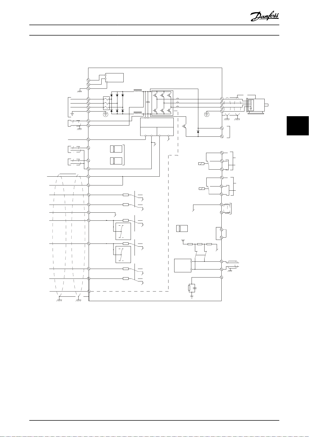
5.3 Wiring Diagram
5 5
MG37K302 Danfoss A/S © 08/2017 All rights reserved. 21
Illustration 5.1 Wiring Diagram
Electrical Installation
VLT® Parallel Drive Modules
5.4 Fuses
5.4.1 Fuse Selection
To protect the drive system in case 1 or more internal
components break down within a drive module, use fuses
and/or circuit breakers at the mains supply side.
5.4.1.1 Branch Circuit Protection
To protect the installation against electrical and re
hazards, protect all branch circuits in an installation against
55
short circuit and overcurrent according to national and
international regulations.
5.4.1.2 Short-circuit Protection
Danfoss recommends the fuses listed in
chapter 5.4.1.3 Recommended Fuses for CE Compliance and
chapter 5.4.1.4 Recommended Fuses for UL Compliance to
achieve CE or UL Compliance in the protection of service
personnel and property against the consequences of
component breakdown in the drive modules.
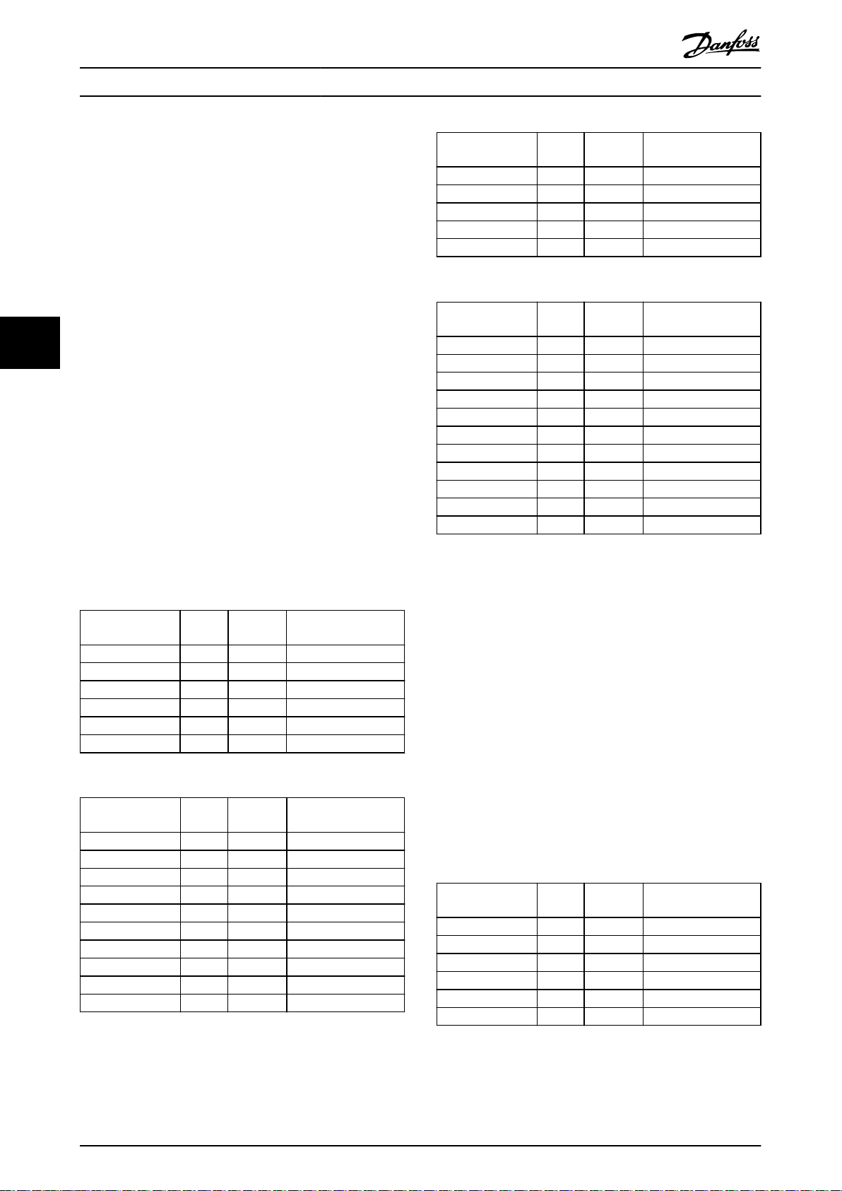
Number of drive
modules
4 N630 N710 aR-1600
4 N710 N800 aR-2000
4 N800 N900 aR-2500
4 N900 N1M0 aR-2500
4 N1M0 N1M2 aR-2500
Table 5.3 6-Pulse Drive Systems (525–690 V AC)
Number of drive
modules
2 N250 N315 aR-550
2 N315 N355 aR-630
2 N355 N400 aR-630
2 N400 N500 aR-630
2 N500 N560 aR-630
2 N560 N630 aR-900
4 N630 N710 aR-900
4 N710 N800 aR-900
4 N800 N900 aR-900
4 N900 N1M0 aR-1600
4 N1M0 N1M2 aR-1600
FC 302 FC 102/
FC 202
FC 302 FC 102/
FC 202
Recommended fuse
(maximum)
Recommended fuse
(maximum)
5.4.1.3 Recommended Fuses for CE
Compliance
Number of drive
modules
2 N450 N500 aR-1600
4 N500 N560 aR-2000
4 N560 N630 aR-2000
4 N630 N710 aR-2500
4 N710 N800 aR-2500
4 N800 N1M0 aR-2500
Table 5.1 6-Pulse Drive Systems (380–500 V AC)
Number of drive
modules
2 N250 N315 aR-630
2 N315 N355 aR-630
2 N355 N400 aR-630
2 N400 N450 aR-800
2 N450 N500 aR-800
4 N500 N560 aR-900
4 N560 N630 aR-900
4 N630 N710 aR-1600
4 N710 N800 aR-1600
4 N800 N1M0 aR-1600
Table 5.2 12-Pulse Drive Systems (380–500 V AC)
FC 302 FC 102/
FC 202
FC 302 FC 102/
FC 202
Recommended fuse
(maximum)
Recommended fuse
(maximum)
Table 5.4 12-Pulse Drive Systems (525–690 V AC)
5.4.1.4 Recommended Fuses for UL
Compliance
The drive modules are supplied with built-in AC
•
fuses. The modules have been qualied for
100 kA short-circuit current rating (SCCR) for the
standard busbar congurations at all voltages
(380–690 V AC).
If no power options or extra busbars are
•
connected externally, the drive system is qualied
for 100 kA SCCR with any Class L or Class T ULlisted fuses connected at the input terminals of
the drive modules.
Do not exceed the listed fuse rating in Table 5.6
•
to Table 5.7 with the current rating of the Class L
or Class T fuses.
Number of drive
modules
2 N450 N500 1600 A
4 N500 N560 2000 A
4 N560 N630 2000 A
4 N630 N710 2500 A
4 N710 N800 2500 A
4 N800 N1M0 2500 A
Table 5.5 6-Pulse Drive Systems (380–500 V AC)
FC 302 FC 102/
FC 202
Recommended fuse
(maximum)
22 Danfoss A/S © 08/2017 All rights reserved. MG37K302

Electrical Installation Installation Guide
Number of drive
modules
2 N250 N315 630 A
2 N315 N355 630 A
2 N355 N400 630 A
2 N400 N450 800 A
2 N450 N500 800 A
4 N500 N560 900 A
4 N560 N630 900 A
4 N630 N710 1600 A
4 N710 N800 1600 A
4 N800 N1M0 1600 A
Table 5.6 12-Pulse Drive Systems (380–500 V AC)
Any minimum 500 V UL-listed fuse can be used for the 380–500 V AC
drive systems.
Number of drive
modules
4 N630 N710 1600 A
4 N710 N800 2000 A
4 N800 N900 2500 A
4 N900 N1M0 2500 A
4 N1M0 N1M2 2500 A
FC 302 FC 102/
FC 202
FC 302 FC 102/
FC 202
Recommended fuse
(maximum)
Recommended fuse
(maximum)
5 5
Table 5.7 6-Pulse Drive Systems (525–690 V AC)
Number of drive
modules
2 N250 N315 550 A
2 N315 N355 630 A
2 N355 N400 630 A
2 N400 N500 630 A
2 N500 N560 630 A
2 N560 N630 900 A
4 N630 N710 900 A
4 N710 N800 900 A
4 N800 N900 900 A
4 N900 N1M0 1600 A
4 N1M0 N1M2 1600 A
Table 5.8 12-Pulse Drive Systems (525–690 V AC)
Any minimum 700 V UL-listed fuse can be used for the 525–690 V AC
drive systems.
FC 302 FC 102/
FC 202
Recommended fuse
(maximum)
MG37K302 Danfoss A/S © 08/2017 All rights reserved. 23

Electrical Installation
VLT® Parallel Drive Modules
5.5 Electrical Kit Installation
This section describes how the electrical kit is used to
connect 2 or 4 drive modules in parallel - to provide
controlled power to an AC motor. A diagram is provided
for each of the 4 congurations which, if followed, meet
specic agency approvals and certications. If designing
and building other congurations, seek agency approvals
or certications apart from Danfoss.
Read this section for guidance in making electrical
connections when assembling the drive modules into a
55
panel.
5.6 DC Bus Fuse Installation
DC fuses are provided in the basic kit. Install the DC fuses
at the available DC terminals at individual drive modules,
using the recommended bolts. Each DC fuse has a xture
for mounting the microswitches, which are used to detect
a fuse failure. See Illustration 3.3. Install the supplied
harness between the microswitch terminals and the brake
fault jumper port on the top of the drive modules. If the
jumper is not installed properly, the unit does not power
up and the error Brake IGBT Fault is shown. The
microswitch has 3 terminals: NO, NC, and COM. Connect
the wire harness between the NC and COM terminals. If it
is connected between any other terminals, the unit does
not power up, and the error Brake IGBT Fault is shown.
NOTICE
The microswitch is a snap t onto the fuse. Ensure that
the switch is properly installed on the fuses.
5.7 Motor Connections
5.7.1 Motor Cables
See chapter 7.6 Cable Specications for more information on
wire type and sizes.
NOTICE
SHIELDED CABLE LENGTH
With a standard VLT® Parallel Drive Modules drive
system, shielded cables up to 150 m (492 ft) long or
unshielded up to 300 m (984 ft) long provide full voltage
at the motor. If this cable length is exceeded, use a
dU/dt lter. For information on the selection of a dU/dt
lter, refer to the VLT® Parallel Drive Modules Design
Guide.
motor cable. Use motor cables with rated voltage specication of at least 0.6/1 kV. Cables in this range provide
good resistance to insulation breakdown.
5.7.1.2 Dimensions
Follow local codes for current capacity data for cables and
conductors. Widely used codes include: NFPA 70, EN
60204-1, VDE 0113-1, and VDE 0298-4. Overdimensioning
for harmonics is not required.
5.7.1.3 Length
Keep cables as short as possible. Voltage drop and heat
dissipation depends on the frequency and is approximately
proportional to cable length. Consult the cable
manufacturer specications regarding the length and
expected voltage drop when connected to the drive
system. See chapter 7.6 Cable Specications.
5.7.1.4 Shielding
The following factors are important for eective shielding:
Make sure that the amount of cable surface
•
covered by the shield is at least 80%.
Use a single-layer braided copper shield. Ensure
•
that the shield is braided to reduce surface area
for leakage currents.
Use cables with double shielding to improve the
•
attenuation of interference further. Twisted
conductors reduce magnetic elds.
Use cables that are shielded at both ends
•
between the drive system and the motor.
To comply with radio frequency interference
•
limits, shield the cables between the drive system
and the motor at both ends.
Ensure that the shield fully surrounds the cable.
•
Route cable glands or cable clamps directly to
•
the grounding point.
Keep connections as short as possible at each
•
end of the cable.
Bridge shield gaps such as terminals, switches, or
•
contactors by using connections with the lowest
possible impedance and the largest possible
surface area.
NOTICE
TWISTED SHIELD ENDS (PIGTAILS)
5.7.1.1 Voltage Rating
Peak voltages up to 2.8 times the mains voltage of the
VLT® Parallel Drive Modules drive system can occur in the
motor cable. High peak voltages can severely stress the
Twisted shield ends increase the shield impedance at
higher frequencies, which reduces the shield eect and
increases the leakage current. To avoid twisted shield
ends, use integrated shield clamps. Refer to
Illustration 5.2.
24 Danfoss A/S © 08/2017 All rights reserved. MG37K302

1
2
130BE747.10
PE
PEPE
PE
PTC / Thermistor
R
OFF
ON
<800 Ω
+10V
130BA152.10
>2.7 kΩ
12 13 18 37322719 29 33 20
5550
39 42 53 54
555039 42 53 54
R
<3.0 k Ω
>3.0 k Ω
+10V
130BA153.11
PTC / Thermistor
OFF
ON
PTC / Thermistor
OFF
ON
+24V
12 13 18 3732
A
2719 29 33B20
GND
R<6.6 k Ω >10.8 k Ω
130BA151.11
Electrical Installation Installation Guide
1 Correct grounding of shielded ends
2 Incorrect grounding using twisted shield ends (pigtail)
Illustration 5.2 Example of Shield Ends
Using a digital input and 24 V as supply
Illustration 5.5 PTC Thermistor Connection - Digital Input with
24 V Supply
5 5
Check that the selected supply voltage follows the specication of the used thermistor element.
5.7.2 Types of Thermal Protection
5.7.2.1 PTC Thermistor
Using a digital input and 10 V supply
Illustration 5.3 PTC Thermistor Connection - Digital Input with
10 V Supply
Using an analog input and 10 V supply
Input digital/
analog
Supply
voltage [V]
Trip resistancekΩReset
Digital 10 >2.7
Analog 10 >3.0
Digital 24 >10.8
Table 5.9 PTC Thermistor Resistance Parameters
resistance
<800 Ω
<3.0 kΩ
<6.6 kΩ
Illustration 5.4 PTC Thermistor Connection - Analog Input with
10 V Supply
MG37K302 Danfoss A/S © 08/2017 All rights reserved. 25

0
500
1000
1500
2000
2500
3000
3500
4000
4500
-25 0 25 50 7 5 100 125 150
Temperature [°C]
Resistance [Ohm]
KTY type 1 KTY type 2 KTY type 3
130BB917.10
Electrical Installation
VLT® Parallel Drive Modules
5.7.2.2 KTY Sensor
The frequency converter handles 3 types of KTY sensors:
KTY Sensor 1: 1 kΩ at 100 °C (212 °F). Philips KTY
•
84-1 is an example.
KTY Sensor 2: 1 kΩ at 25 °C (77 °F). Philips KTY
•
83-1 is an example.
KTY Sensor 3: 1 kΩ at 25 °C (77 °F). Philips
•
KTY-10 is an example.
55
Illustration 5.6 KTY Type Selection
NOTICE
NOTICE
Danfoss is not responsible for the failure of any Klixon
thermal switch.
5.7.3 Motor Terminal Connections
WARNING
INDUCED VOLTAGE
Induced voltage from output motor cables from dierent
frequency converters that are run together can charge
equipment capacitors even with the equipment turned
o and locked out. Failure to run output motor cables
separately or use shielded cables could result in death or
serious injury.
Run output motor cables separately.
•
Or
Use shielded cables.
•
Simultaneously lock out all the frequency
•
converters.
Comply with local and national electrical codes
•
for cable sizes. For maximum cable sizes, see
chapter 7.1 Power-dependent Specications.
Follow motor manufacturer wiring requirements.
•
Do not wire a starting or pole-changing device
•
(for example, Dahlander motor or slip ring
induction motor) between the drive system and
the motor.
5.7.3.1 Motor Cable
PELV COMPLIANCE
If short circuits occur between motor windings and the
sensor, PELV compliance is not achieved when the motor
temperature is monitored via a thermistor or KTY sensor.
Ensure that the sensor is isolated better.
5.7.2.3 Brake Resistor Thermal Switch
Installation
Each drive module has a brake fault jumper connector on
the top plate, which is used to connect the Klixon thermal
switch on the brake resistors. This connector has a preinstalled jumper as shown in Illustration 8.3. The brake fault
jumper must always be in place to ensure proper
operation of the drive module. Without this jumper
connection, the drive module does not allow the inverter
to operate, and a brake IGBT fault is shown.
The thermal switch is a normally-closed type. If the brake
resistor temperature exceeds recommended values, the
thermal switch opens. Use 1 mm2 (18 AWG), reinforced and
doubly insulated wire for the connection. See
Illustration 8.5.
All types of 3-phase asynchronous standard motors can be
used with the drive system.
Connect the motor to the following terminals:
U/T1/96
•
V/T2/97
•
W/T3/98
•
Ground to terminal 99
•
Factory setting is for clockwise rotation with the drive
system output connected as follows:
Terminal number Function
96 Mains U/T1
97 V/T2
98 W/T3
99 Ground
Table 5.10 Motor Cable Terminals
26 Danfoss A/S © 08/2017 All rights reserved. MG37K302

175HA036.11
U
1
V
1
W
1
96 97 98
FC
Motor
U
2
V
2
W
2
U
1
V
1
W
1
96 97 98
FC
Motor
U
2
V
2
W
2
Electrical Installation Installation Guide
Changing motor rotation
Terminal U/T1/96 connected to U-phase
•
Terminal V/T2/97 connected to V-phase
•
Terminal W/T3/98 connected to W-phase
•
5.7.3.2 Motor Terminal Connections in 2Drive Module Systems
Illustration 8.9 and Illustration 8.10 show the bus bar
connections for 6-pulse and 12-pulse 2-drive systems,
respectively. If a common terminal design is used, there is
1 set of motor terminals.
NOTICE
MULTIPLE MOTOR CABLES
If connecting more than 1 set of motor terminals, use
the same number, size, and length of cables for each set
of terminals. For example, do not use 1 cable on one
motor terminal and 2 cables on another motor terminal.
1. Measure between the common terminals and the
rst common point of a phase, typically the
motor terminals.
2. Strip a section of the outer cable insulation.
3. Connect the ground wire to the nearest
protective earth terminal.
4. Connect the 3-phase motor wiring to terminals
U/96, V/97, and W/98 using M10 screws.
5. Tighten the motor terminals. See
chapter 7.9.1 Tightening Torques for Terminals.
5 5
Illustration 5.7 Changing Motor Rotation
The direction of rotation can be changed by switching 2
phases in the motor cable, or by changing the setting of
parameter 4-10 Motor Speed Direction.
Motor rotation check can be performed using
parameter 1-28 Motor Rotation Check and following the
steps shown in Illustration 5.7.
5.7.3.3 Motor Terminal Connections in 4Drive Module Systems
Illustration 8.11 shows the bus bar connections for a 4-drive
system. If a common terminal design is used, there is 1 set
of motor terminals in each cabinet.
NOTICE
MULTIPLE MOTOR CABLES
If connecting more than 1 set of motor terminals, use
the same number, size, and length of cables for each set
of terminals. For example, do not use 1 cable on one
motor terminal and 2 cables on another motor terminal.
1. Measure between the common terminals and the
rst common point of a phase, typically the
motor terminals.
2. Strip a section of the outer cable insulation.
3. Connect the ground wire to the nearest
protective earth (ground) terminal.
4. Connect the 3-phase motor wiring to terminals
U/96, V/97, and W/98 using M10 screws.
5. Tighten the motor terminals. See
chapter 7.9.1 Tightening Torques for Terminals.
MG37K302 Danfoss A/S © 08/2017 All rights reserved. 27

Electrical Installation
VLT® Parallel Drive Modules
5.8 Mains Connections
5.8.1.1 Mains Terminal Connections in 2Drive Module Systems
There are several types of AC mains systems for supplying
power to frequency converters. Each aects the EMC
characteristics of the system. The 5-wire TN-S systems are
regarded as best regarding EMC, while the isolated IT
system is the least preferred.
System
type
TN mains
systems
55
TN-S A 5-wire system with separate neutral (N) and
TN-C A 4-wire system with a common neutral and
TT mains
systems
IT grid
system
Table 5.11 AC Mains Systems and EMC Characteristics
Description
There are 2 types of TN mains distribution systems:
TN-S and TN-C.
protective earth (PE) conductors. It provides the
best EMC properties and avoids transmitting
interference.
protective earth (PE) conductor throughout the
system. The combined neutral and PE conductor
results in poor EMC characteristics.
A 4-wire system with a grounded neutral conductor
and individual grounding of the drive system. It has
good EMC characteristics when grounded properly.
An isolated 4-wire system with the neutral
conductor either not grounded or grounded via an
impedance.
5.8.1 AC Mains Terminal Connections
When making mains connections, observe the following:
Size the wiring based on the input current of the
•
frequency converter. For maximum wire sizes, see
chapter 7.1 Power-dependent Specications.
Comply with local and national electrical codes
•
for cable sizes.
Illustration 8.9 and Illustration 8.10 show the bus bar
connections for 6-pulse and 12-pulse 2-drive systems,
respectively.
If a common terminal design is used with a 6-
•
pulse, 2-drive system, there is 1 set of mains
terminals.
Common terminal design cannot be used with
•
12-pulse mains connections in a 2-drive module
systems. The mains cables are connected directly
to the drive input terminals.
There are individual brake terminals available in
•
each drive module. Connect an equal number of
recommended cables to the individual brake
terminals.
NOTICE
MULTIPLE MAINS CABLES
If connecting more than 1 set of mains terminals, use the
same number, size, and length of cables for each set of
terminals. For example, do not use 1 cable on one mains
terminal and 2 cables on another mains terminal.
1. Measure between the common terminals and the
rst common point of a phase, typically the
mains terminals.
2. For 12-pulse drive modules, the set of cables from
the 1st drive module connects to the starsecondary winding of the 12-pulse transformer.
The set from the 2nd drive module connects to
the delta-secondary winding of the 12-pulse
transformer.
3. Strip a section of the outer cable insulation.
4. Connect the ground wire to the nearest ground
terminal.
5. Connect the 3-phase mains wiring to terminals
R/91, S/92, and T/93 using M10 screws.
6. Tighten the mains terminals. See
chapter 7.9.1 Tightening Torques for Terminals.
28 Danfoss A/S © 08/2017 All rights reserved. MG37K302

Electrical Installation Installation Guide
5.8.1.2 Mains Terminal Connections in 4Drive Module Systems
Illustration 8.11 shows the bus bar connections for 4-drive
systems. If a common terminal design is used, there is 1
set of mains terminals in each cabinet.
NOTICE
MULTIPLE MAINS CABLES
If connecting more than 1 set of mains terminals, use the
same number, size, and length of cables for each set of
terminals. For example, do not use 1 cable on one mains
terminal and 2 cables on another mains terminal.
1. Measure between the common terminals and the
1st common point of a phase.
1a For 6-pulse modules, it is typically the
mains terminals.
1b For 12-pulse drive modules, the set of
cables from the 1st cabinet connects to
the star-secondary winding of the 12pulse transformer. The set from the 2
cabinet connects to the delta-secondary
winding of the 12-pulse transformer.
2. Strip a section of the outer cable insulation.
3. Connect the ground wire to the nearest ground
terminal.
4. Connect the 3-phase mains wiring to terminals
R/91, S/92, and T/93 using M10 screws.
5. Tighten the mains terminals. See
chapter 7.9.1 Tightening Torques for Terminals.
nd
NOTICE
Danfoss is not responsible for any failure or malfunction
in the disconnector/contactor switch.
5 5
5.8.2 12-Pulse Disconnector Conguration
This section describes how to use a disconnector for a 12pulse drive system. When using disconnectors or
contactors, make sure to install an interlock. When
installed, both contactors or disconnectors should close to
avoid 1 set of rectiers not working. See Illustration 8.1 for
a diagram of these connections.
The selected contactors or mains disconnectors should
have NC auxiliary contacts routed as shown. Connect the
interlock in series with the Klixon switch of the brake. If
only 1 contactor/disconnector has closed, the LCP shows
the error Brake IGBT Fault and does not allow the drive
system to power the motor. Illustration 8.2 shows a BRF
connection with 12-pulse disconnector and interlock.
NOTICE
If the brake option is not selected, the Klixon switch can
be bypassed.
MG37K302 Danfoss A/S © 08/2017 All rights reserved. 29

Electrical Installation
VLT® Parallel Drive Modules
5.8.3 Discharge Resistors
There are common positive and negative DC terminals on each drive module. If a shorter time to achieve the reduced run
functionality is wanted, connect the external discharge resistor for quicker discharge of DC-link voltage. It is possible to
connect a discharge resistor in an additional cabinet, through a contactor. This discharge contactor should have an interlock
with the mains contactor/disconnector’s auxiliary NC contacts to avoid a discharge when the drive system is powered.
Illustration 8.7 shows a 4-drive system with discharge resistor connections.
Base the selection of a discharge resistor on the energy and power levels given in Table 5.12 for
dierent power sizes, on
both 12-pulse and 6-pulse systems.
55
FC 102
FC 202
FC 302 N450 N500 N560 N630 N710 N800
Drive modules required
(HO rating)
Resistance required to reduce DC
voltage below 50 V within 300 s
(5 minutes), Ω
Power rating of resistor (W) 182 242 303 303 363 363
Energy dissipated by resistor (J) 7773 10365 12956 12956 15547 15547
Table 5.12 Discharge Resistors Recommended for Drive Systems with 380–480 V AC Mains Supply
FC 102
FC 202
FC 302 N560 N630 N710 N800 N900 N1M0
Drive modules required
(HO rating)
Resistance required to reduce DC
voltage below 50 V within 300 s
(5 minures), Ω
Power rating of resistor (W) 230 345 459 459 459 459
Energy dissipated by resistor (J) 8819 13229 17638 17638 17638 17638
N500 N560 N630 N710 N800 N1M0
2xN250 4xN160 4xN200 4xN200 4xN250 4xN250
3036 2277 1822 1822 1518 1518
N630 N710 N800 N900 N1M0 N1M2
2xN315 4xN200 4xN250 4xN250 4xN315 4xN315
4571 3047 2285 2285 2285 2285
Table 5.13 Discharge Resistors Recommended for Drive Systems with 525–690 V AC Mains Supply
NOTICE
Danfoss is not responsible for any failure or malfunction of the resistor, or for any misconnections made by the installer.
NOTICE
The wire used with the brake resistor should be double-insulated or have reinforced insulation.
30 Danfoss A/S © 08/2017 All rights reserved. MG37K302

Electrical Installation Installation Guide
5.9 Control Shelf Installation
The control shelf is preassembled. However, verify its various connections against the connection diagram. Illustration 8.6
shows the various control shelf connections.
NOTICE
INCORRECT CONNECTION ORDER
If the connections are not made in the correct order, the drive modules do not function.
Check the following connections:
Connection of the 44-pin ribbon cable between the MDCIC and the control card.
•
When used, Safe Torque O (STO) jumper connection must be made between the 12th and 27th pins to ensure
•
proper STO operation.
Connect the 44-pin ribbon cable to the MDCIC connectors in the correct order.
•
- For systems with 4 drive modules, connect the ribbon cables to inverter 1, inverter 2, inverter 3, and then
inverter 4.
- For systems with 2 drive modules, connect the ribbon cables to inverter 1, then inverter 2. Leave inverter
3 and inverter 4 terminals unconnected.
5 5
NOTICE
SCALING CARD POSITION
If the scaling cards are not placed in the correct order, the drive modules do not function.
Place the corresponding current scaling card on each respective connector.
•
- For systems with 4 drive modules, Inverter 1, Inverter 2, Inverter 3, and Inverter 4.
- For systems with 2 drive modules, Inverter 1 and Inverter 2. Leave connectors Inverter 3 and Inverter 4
unconnected.
Do not reverse the current scaling card. Check that the PCB spacer is xed on the MDCIC board.
•
Ensure correct installation of the STO relay and the power supply on the DIN rail. Make the connections as shown
•
in Illustration 8.6.
The external supply (100–230 V) must be available at terminals 1 and 2 on the terminal block.
•
Make more checks to ensure that the wiring of the fuse microswitches and the BRF jumpers are properly routed.
•
Check that all the screws on the PCBs are secure.
•
To ensure proper EMC protection, verify that the MDCIC plate is properly attached to the control shelf assembly.
•
Control Wiring Connections
5.10
Make sure to use the provided wire pathway when routing the control wires from the bottom of the drive system cabinet to
the control terminal.
MG37K302 Danfoss A/S © 08/2017 All rights reserved. 31

130BE745.11
1
3
5
4
2
Electrical Installation
VLT® Parallel Drive Modules
5.10.1 Control Cable Routing
Cable routing
Route the cable inside the drive cabinets as shown in Illustration 5.8. Wire routing for a 2-drive conguration is identical,
except for the number of drive modules used.
55
1 Microswitch cable 4 44-pin ribbon cable from MDCIC to drive module 4
2 Ferrite core 5 Bracket to support ribbon cable
3 44-pin ribbon cable from MDCIC to drive modules 1 and 2 – –
Illustration 5.8 Control Cable Routing for a 4-Drive System
32 Danfoss A/S © 08/2017 All rights reserved. MG37K302

130BE062.10
2
3
4
1
Electrical Installation Installation Guide
5.10.2 Control Wiring
Isolate the control wiring from the high-power components in the drive modules.
•
When the drive module is connected to a thermistor, ensure that the thermistor control wiring is shielded and
•
reinforced/double insulated. A 24 V DC supply voltage is recommended. See Illustration 5.9.
NOTICE
MINIMIZE INTERFERENCE
To minimize interference, keep control wires as short as possible and separate them from high-power cables.
The control terminals are on the control shelf, directly below the LCP. The control cable is routed at the bottom of the
cabinet.
1. Follow the designated control cable routing as shown in chapter 5.10.1 Control Cable Routing.
2. Tie down all control wires.
3. Ensure optimum electrical immunity by properly connecting the shields.
Fieldbus connection
For details, see the relevant eldbus instructions.
1. Follow the designated control cable routing as shown in chapter 5.10.1 Control Cable Routing.
2. Tie down all control wires.
3. Connect the relevant options on the control card.
5.10.2.1 Control Terminal Types
Illustration 5.9 shows the removable frequency converter connectors. Terminal functions and default settings are summarized
in Table 5.14. See Illustration 5.9 for the location of the control terminals within the unit.
5 5
1 Terminals (+)68 and (-)69 are for an RS485 serial communication connection.
2 USB port available for use with the MCT 10 Set-up Software.
3 2 analog inputs, 1 analog output, 10 V DC supply voltage, and commons for the inputs and output.
4 4 programmable digital inputs terminals, 2 extra digital terminals programmable as either input or output, a 24 V DC terminal supply
voltage, and a common for optional customer-supplied 24 V DC voltage.
Illustration 5.9 Control Terminal Locations
MG37K302 Danfoss A/S © 08/2017 All rights reserved. 33

Electrical Installation
VLT® Parallel Drive Modules
Terminal Parameter Default
setting
Digital inputs/outputs
12, 13 – +24 V DC
18 Parameter 5-10 Terminal 18 Digital Input [8] Start
19 Parameter 5-11 Terminal 19 Digital Input [10] Reversing
32 Parameter 5-14 Terminal 32 Digital Input [0] No operation
33 Parameter 5-15 Terminal 33 Digital Input [0] No operation
27 Parameter 5-12 Terminal 27 Digital Input [2] Coast inverse Selectable for digital input and
29 Parameter 5-13 Terminal 29 Digital Input [14] Jog
20 – – Common for digital inputs and 0 V
55
37 – Safe Torque O (STO) Safe input (optional). Used for STO.
Analog inputs/outputs
39 – – Common for analog output
42 Parameter 6-50 Terminal 42 Output Speed 0 – high limit
50 – +10 V DC
53 Parameter group 6-1* Analog Input 1 Reference Analog input. Selectable for
54 Parameter group 6-2* Analog Input 2 Feedback
55 – – Common for analog input
Serial communication
61 – – Integrated RC-lter for cable shield.
Digital inputs. 24 V DC supply
voltage. Maximum output current
is 200 mA total for all 24 V loads.
Usable for digital inputs and
external transducers.
output. Default setting is input.
potential for 24 V supply.
Programmable analog output. The
analog signal is 0–20 mA or 4–
20 mA at a maximum of 500 Ω
10 V DC analog supply voltage.
15 mA maximum commonly used
for potentiometer or thermistor.
voltage or current. Switches A53
and A54 select mA or V.
ONLY for connecting the shield
when experiencing EMC problems.
Description
68 (+) Parameter group 8-3 FC Port Settings – RS485 Interface. A control card
69 (-) Parameter group 8-3 FC Port Settings –
Relays
01, 02, 03 Parameter 5-40 Function Relay [0] [9] Alarm Form C relay output. Usable for AC
04, 05, 06 Parameter 5-40 Function Relay [1] [5] Running
Table 5.14 Terminal Description
switch is provided for termination
resistance.
or DC voltage and resistive or
inductive loads.
Extra terminals:
Two form C relay outputs. Location of the outputs depends on frequency converter conguration.
•
Terminals on built-in optional equipment. See the manual provided with the equipment option.
•
34 Danfoss A/S © 08/2017 All rights reserved. MG37K302

130BT306.10
130BE063.10
1
2
3
1
2
N O
Electrical Installation Installation Guide
5.10.2.2 Wiring to Control Terminals
Terminal plugs can be removed for easy access.
Illustration 5.10 Removal of Control Terminals
5.10.2.3 Enabling Motor Operation
(Terminal 27)
A jumper wire is required between terminal 12 (or 13) and
terminal 27 for the frequency converter to operate when
using factory default programming values.
Digital input terminal 27 is designed to receive
•
24 V DC external interlock command.
When no interlock device is used, wire a jumper
•
between control terminal 12 (recommended) or
13 to terminal 27. The jumper provides an
internal 24 V signal on terminal 27.
When the status line at the bottom of the LCP
•
reads AUTO REMOTE COAST, it indicates that the
unit is ready to operate but is missing an input
signal on terminal 27.
When factory installed optional equipment is
•
wired to terminal 27, do not remove that wiring.
5.10.2.4 Voltage/Current Input Selection
(Switches)
The analog mains terminals 53 and 54 allow the setting of
the input signal to voltage (0–10 V) or current (0/4–
20 mA). See Illustration 5.9 for the location of the control
terminals within the drive system.
Default parameter settings:
Terminal 53: Speed reference signal in open loop
•
(see parameter 16-61 Terminal 53 Switch Setting).
Terminal 54: Feedback signal in closed loop (see
•
parameter 16-63 Terminal 54 Switch Setting).
NOTICE
REMOVE POWER
Remove power to the frequency converter before
changing switch positions.
1. Remove the LCP (see Illustration 5.11).
2. Remove any optional equipment covering the
switches.
3. Set switches A53 and A54 to select the signal
type. U selects voltage, I selects current.
5 5
MG37K302 Danfoss A/S © 08/2017 All rights reserved. 35
1 Bus termination switch
2 A54 switch
3 A53 switch
Illustration 5.11 Locations of Bus Termination Switch and
Switches A53 and A54

130BC554.11
Relay 1
Relay 2
03
02
240 V AC, 2 A
01
06
05
04
240 V AC, 2 A
400 V AC, 2 A
400 V AC, 2 A
Electrical Installation
VLT® Parallel Drive Modules
5.10.2.5 RS485 Serial Communication
An RS485 serial communications bus can be used with the
drive system. Up to 32 nodes can be connected as a bus,
or via drop cables from a common trunk line to 1 network
segment. Repeaters can be used to divide network
segments. Each repeater functions as a node within the
segment in which it is installed. Each node connected
within a given network must have a unique node address,
across all segments.
Connect RS485 serial communication wiring to
•
55
terminals (+)68 and (-)69.
Terminate each segment at both ends, using
•
either the termination switch (bus term on/o,
see Illustration 5.11) on the drive module, or a
biased network termination resistor.
Connect a large surface of the shield to ground,
•
for example with a cable clamp or a conductive
cable gland.
Maintain the same ground potential throughout
•
the network by applying potential-equalizing
cables.
Prevent impedance mismatch by using the same
•
type of cable throughout the entire network.
Relay 1
Terminal 01: Common
•
Terminal 02: Normally open 400 V AC
•
Terminal 03: Normally closed 240 V AC
•
Relay 2
Terminal 04: Common
•
Terminal 05: Normally open 400 V AC
•
Terminal 06: Normally closed 240 V AC
•
Relay 1 and relay 2 are programmed in
parameter 5-40 Function Relay, parameter 5-41 On Delay,
Relay, and parameter 5-42 O Delay, Relay.
Use VLT® Relay Card MCB 105 option module for extra
relay outputs.
Cable Shielded twisted pair (STP)
Impedance
Maximum cable length
Station-to-station [m
(ft)]
Total including drop
lines [m (ft)]
Table 5.15 Cable Information
120 Ω
500 (1640)
1200 (3937)
5.10.3 Safe Torque O (STO)
To run STO, extra wiring for the drive system is required.
Refer to VLT
Operating Instructions for further information.
5.11
The relay terminal is on the top plate of the drive module.
See Illustration 3.1. Use an extended wiring harness to
connect the relay terminal of drive module 1 (the drive
module on the far left) to the terminal blocks on the
control shelf.
®
Frequency Converters Safe Torque O
Relay Output
NOTICE
For reference, drive modules are numbered from left to
right.
Illustration 5.12 Extra Relay Outputs
36 Danfoss A/S © 08/2017 All rights reserved. MG37K302

Electrical Installation Installation Guide
5.12 EMC Recommendations
The following is a guideline to good engineering practice
when installing frequency converters. Follow these
guidelines in compliance with EN/IEC 61800-3 First
environment. If the installation is in EN/IEC 61800-3 Second
environment, industrial networks, or in an installation with
its own transformer, deviation from these guidelines is
allowed but not recommended.
Good engineering practice to ensure EMC-correct
electrical installation:
Use only braided shielded/armored motor cables
•
and braided shielded control cables. The shield
provides a minimum coverage of 80%. The shield
material must be metal, not limited to but
typically copper, aluminum, steel, or lead. There
are no special requirements for the mains cable.
Installations using rigid metal conduits are not
•
required to use shielded cable, but the motor
cable must be installed in conduit separate from
the control and mains cables. Full connection of
the conduit from the frequency converter to the
motor is required. The EMC performance of
exible conduits varies a lot and information from
the manufacturer must be obtained.
Connect the shield conduit to ground at both
•
ends for motor cables and for control cables.
Sometimes, it is not possible to connect the
shield in both ends. If so, connect the shield at
the frequency converter. See also
chapter 5.12.2 Grounding of Shielded Control
Cables.
Avoid terminating the shield with twisted ends
•
(pigtails). It increases the high frequency
impedance of the shield, which reduces its
eectiveness at high frequencies. Use low
impedance cable clamps or EMC cable glands
instead.
Avoid using unshielded motor or control cables
•
inside cabinets housing the frequency converter,
whenever possible.
Leave the shield as close to the connectors as possible.
Illustration 5.13 shows an example of an EMC-correct
electrical installation of an IP20 frequency converter. The
frequency converter is tted in an installation cabinet with
an output contactor and connected to a PLC, which is
installed in a separate cabinet. Other ways of doing the
installation could have just as good an EMC performance,
provided the guidelines to engineering practice are
followed.
If the installation is not carried out according to the
guideline, and if unshielded cables and control wires are
used, some emission requirements are not in compliance,
although the immunity requirements are
fullled.
5 5
MG37K302 Danfoss A/S © 08/2017 All rights reserved. 37

Reinforced protective ground
Mains supply
L1
L2
L3
PE
PLC
Control cables
Minimum 16 mm
2
equalizing cable
Minimum 200 mm
between control
cables, motor cable,
and mains cable
Motor, 3-phases and protective ground
PLC, etc. Panel
Output contactor, etc.
Ground rail
Cable insulation stripped
All cable entries in 1 side of panel
130BA048.14
Electrical Installation
VLT® Parallel Drive Modules
55
Illustration 5.13 EMC-correct Electrical Installation of a Frequency Converter in Cabinet
38 Danfoss A/S © 08/2017 All rights reserved. MG37K302

175ZA166.13
0,01 0,1 1 10 100 MHz
10²
10³
10¹
1
10¹
10²
10
10³
10
a
b
c
d
e
f
g
The lower the Z the better the cable shielding performance
Transfer impedance, Z
t
mΩ/m
Electrical Installation Installation Guide
5.12.1 Using Shielded Control Cables
Danfoss recommends braided shielded/armored cables to optimize EMC immunity of the control cables and the EMC
emission from the motor cables.
The ability of a cable to reduce the incoming and outgoing radiation of electric noise depends on the transfer impedance
(ZT). The shield of a cable is normally designed to reduce the transfer of electric noise. However, a shield with a lower
transfer impedance (ZT) value is more eective than a shield with a higher transfer impedance (ZT).
Cable manufacturers rarely state the transfer impedance (ZT), but it is often possible to estimate transfer impedance (ZT) by
assessing the physical design of the cable, such as:
The conductibility of the shield material.
•
The contact resistance between the individual shield conductors.
•
The shield coverage, that is the physical area of the cable covered by the shield - often stated as a percentage
•
value.
Shield type, that is braided or twisted pattern.
•
5 5
a Aluminum-clad with copper wire.
b Twisted copper wire or armored steel wire cable.
c Single-layer braided copper wire with varying percentage shield coverage (this type of cable is the typical Danfoss
d Double-layer braided copper wire.
e Twin layer of braided copper wire with a magnetic, shielded/armored intermediate layer.
f Cable that runs in copper tube or steel tube.
g Lead cable with 1.1 mm (0.04 in) wall thickness.
Illustration 5.14 Cable Shielding Performance
MG37K302 Danfoss A/S © 08/2017 All rights reserved. 39
reference cable).

1
2
PE
FC
PE
PLC
130BB922.12
PE PE
<10 mm
100nF
FC
PE
PE
PLC
<10 mm
130BB609.12
PE
FC
PE
FC
130BB923.12
PE PE
69
68
61
69
68
61
1
2
<10 mm
PE
FC
PE
FC
130BB924.12
PE PE
69
69
68
68
1
2
<10 mm
Electrical Installation
VLT® Parallel Drive Modules
5.12.2 Grounding of Shielded Control Cables
Correct shielding
The preferred method usually is to secure control and
serial communication cables with shielding clamps
provided at both ends to ensure best possible high
Avoid EMC noise on serial communication
This terminal is connected to ground via an internal RC
link. To reduce interference between conductors, use
twisted-pair cables.
frequency cable contact. If the ground potential between
the frequency converter and the PLC is dierent, electric
noise can occur that disturbs the entire system. Solve this
problem by tting an equalizing cable next to the control
cable. Minimum cable cross-section: 16 mm2 (4 AWG).
55
1
Minimum 16 mm2 (4 AWG)
2 Equalizing cable
Illustration 5.15 Correct Shielding
50/60 Hz ground loops
With long control cables, ground loops can occur. To
eliminate ground loops, connect 1 end of the shield-toground with a 100 nF capacitor (keeping leads short).
1
Minimum 16 mm2 (4 AWG)
Illustration 5.17 Recommended Method for Avoiding EMC
Noise
Alternatively, the connection to terminal 61 can be
omitted:
2 Equalizing cable
Illustration 5.16 Avoiding Ground Loops
1
Minimum 16 mm2 (4 AWG)
2 Equalizing cable
Illustration 5.18 Shielding without Using Terminal 61
40 Danfoss A/S © 08/2017 All rights reserved. MG37K302

Initial Start-up Installation Guide
6 Initial Start-up
6.1 Pre-start Check List
Before completing installation of the unit, inspect the entire installation as detailed in Table 6.1. Mark the check-list items
when they are completed.
Inspect for Description
Auxiliary equipment•Look for auxiliary equipment, switches, disconnects, or input fuses/circuit breakers that reside on the input
power side of the drive system or on the output side to the motor. Ensure that they are ready for full-
speed operation.
Check function and installation of any sensors used for feedback to the drive system.
•
Remove any power factor correction caps on motor(s).
•
Adjust any power factor correction caps on the mains side and ensure that they are dampened.
•
Cable routing
Control wiring
Cooling clearance
Ambient conditions•Check that requirements for ambient conditions are met.
Fusing and circuit
breakers
Grounding
Input and output
power wiring
Panel interior
Switches
Vibration
Ensure that motor wiring and control wiring are separated or shielded, or in 3 separate metallic conduits
•
for high-frequency interference isolation.
Check for broken or damaged wires and loose connections.
•
Check that control wiring is isolated from power and motor wiring for noise immunity.
•
Check the voltage source of the signals, if necessary.
•
Using shielded cable or twisted pair is recommended. Ensure that the shield is terminated correctly.
•
Check that the DC-link fuse and microswitch xtures are correct. Check the microswitch cabling and the
•
connectors in the top of the drive module.
Check that there is 225 mm (9 in) of top clearance for adequate cooling.
•
Check for proper fusing or circuit breakers.
•
Check that all fuses are inserted rmly and are in operational condition, and that all circuit breakers are in
•
the open position.
Check for good ground connections that are tight and free of oxidation.
•
Grounding to conduit, or mounting the back panel to a metal surface, is not a suitable grounding.
•
Check for loose connections.
•
Check that motor and mains are in separate conduit or separated shielded cables.
•
Check that the shields are properly grounded.
•
Check that the DC-link connections are properly made.
•
Inspect that the unit interior is free of dirt, metal chips, moisture, and corrosion.
•
Check that the unit is mounted on an unpainted, metal surface.
•
Ensure that all switch and disconnect settings are in the proper positions.
•
Check that the unit is mounted solidly, or that shock mounts are used, as necessary.
•
Check for an unusual amount of vibration.
•
☑
6
6
Table 6.1 Installation Check List
MG37K302 Danfoss A/S © 08/2017 All rights reserved. 41

6
Initial Start-up
VLT® Parallel Drive Modules
CAUTION
POTENTIAL HAZARD IN THE EVENT OF
INTERNAL FAILURE
There is a risk of personal injury when the drive modules
are not properly closed.
Before applying power, ensure that all safety
•
covers are in place and securely fastened.
6.2 Safety Instructions
See chapter 2 Safety for general safety instructions.
WARNING
HIGH VOLTAGE
The drive system contains high voltage when connected
to AC mains input power, DC supply, or load sharing.
Failure to perform installation, startup, and maintenance
by qualied personnel can result in death or serious
injury.
Before applying power:
1. Ensure that input power to the unit is OFF and
locked out. Do not rely on the drive system’s
disconnect switches for input power isolation.
2. Verify that there is no voltage on mains terminals
L1 (91), L2 (92), and L3 (93), phase-to-phase, and
phase-to-ground.
3. Verify that there is no voltage on motor terminals
96 (U), 97 (V ), and 98 (W), phase-to-phase, and
phase-to-ground.
4. Conrm continuity of the motor by measuring
resistance values on U–V (96–97), V–W (97–98),
and W–U (98–96).
5. Check for proper grounding of the drive system
and the motor.
6. Inspect the drive system for loose connections on
the terminals.
7. Conrm that the supply voltage matches the
voltage of the drive system and the motor.
Applying Power
6.3
WARNING
UNINTENDED START
When the drive system is connected to AC mains, the
motor can start at any time. Unintended start during
programming, service, or repair work can result in death,
serious injury, or property damage. The motor can start
via any of the following:
An external switch.
•
A eldbus command.
•
An input reference signal from the LCP.
•
A cleared fault condition.
•
Remote operation using MCT 10 Set-up
•
Software.
To prevent unintended motor start:
Disconnect the drive system from AC mains.
•
Press [O/Reset] on the LCP, before
•
programming parameters.
The drive system, motor, and any driven
•
equipment must be fully wired and assembled
when the drive is connected to AC mains.
Apply power to the drive system, according to the
following steps:
1. Conrm that the input voltage is balanced within
3%. If not, correct the input voltage imbalance
before proceeding. Repeat this procedure after
the voltage correction.
2. Ensure that the wiring of any optional equipment
matches the installation application.
3. Ensure that all operator devices are in the OFF
position.
4. Close all panel doors and securely fasten all
covers.
5. Apply power to the drive system. DO NOT start
the drive system now. For units with a disconnect
switch, turn the switch to the ON position to
apply power to the drive system.
42 Danfoss A/S © 08/2017 All rights reserved. MG37K302

130BE712.10
Auto
on
Reset
Hand
on
O
Status
Quick
Menu
Main
Menu
Alarm
Log
Back
Cancel
Info
OK
On
Alarm
Warn.
1
3
2
Initial Start-up Installation Guide
6.4 Conguring the Drive System
Before the drive system is fully functional, it is necessary to
congure the unit on the local control panel (LCP). The
top-level drive system label is needed for the following
steps. Refer to Illustration 4.1.
1. Apply power. At power-up, the LCP display shows
alarm 250, New spare part.
2. Press [Main Menu] twice on the LCP. See
Illustration 6.1.
3. Press the navigation keys and the [OK] key to
navigate to parameter group 14-** Special
Functions. Then scroll down to
parameter 14-23 Typecode Setting.
4. Scroll through the submenu to match the 39
characters in the typecode to the 20 index
groups. See Table 6.2. Press [OK] to enter the
value.
5. At index number 20, select Save to EEPROM and
press [OK]. When the system nishes writing the
EEPROM data, the display shows No Function.
6. Remove power to the drive system, and then
reapply power. Press [RESET] to clear the alarm.
NOTICE
INCORRECT TYPECODE ENTERED
If the wrong typecode is entered, scroll to
parameter 14-29 Service Code and enter 00006100. This
step allows access to parameter 14-23 Typecode Setting to
reenter the typecode.
1 LCP display
2 [Main Menu] key
3 Power-on indicator light
Illustration 6.1 Local Control Panel (LCP)
6
6
Index Description Typecode units
[0] Product group 1–3
[1] Series 4–6
[2] Power 7–10
[3] Voltage 11–12
[4] Enclosure 13–15
[5] RFI lter 16–17
[6] Brake & stop 18
[7] Display 19
[8] Coating 20
[9] Mains options 21
[10] Adaptation A 22
[11] Adaptation B 23
[12] Software 24–27
[13] Language 28
[14] Options A 29–30
[15] Options B 31–32
[16] Options C0 33–34
[17] Options C1 35
[18] Options C 36–37
[19] Options D 38–39
Table 6.2 Typecode Index
MG37K302 Danfoss A/S © 08/2017 All rights reserved. 43

6
Initial Start-up
VLT® Parallel Drive Modules
6.5 Testing the Motor Operation
1. Press [Main Menu] twice on the LCP.
2. Press the navigation keys and the [OK] key to
navigate to parameter group 1-** Load and Motor
and press [OK].
3. Navigate to parameter 1-23 Motor Frequency and
enter the frequency from the motor nameplate.
4. Navigate to parameter 1-23 Motor Frequency and
enter the current from the motor nameplate.
5. Navigate to parameter 1-25 Motor Nominal Speed
and enter the speed from the motor nameplate.
6. Press [Status] to return to the operational display.
7. Press [Hand On].
8.
Press [▲] to accelerate the motor.
9.
Press [▼] to decelerate the motor.
10. Press [O].
44 Danfoss A/S © 08/2017 All rights reserved. MG37K302

Specications Installation Guide
7 Specications
7.1 Power-dependent Specications
7.1.1
VLT® HVAC Drive FC 102
Power range N315 N355 N400 N450 N500
Drive modules 2 2 2 2 2
Rectier conguration 12-pulse 6-pulse/12-pulse
High/normal load NO NO NO NO NO
Output current [A]
Continuous (at 380–440 V) 588 658 745 800 880
Intermittent (60 s overload) at 400 V 647 724 820 880 968
Continuous (at 460/500 V) 535 590 678 730 780
Intermittent (60 s overload) at 460/500 V 588 649 746 803 858
Input current [A]
Continuous (at 400 V) 567 647 733 787 875
Continuous (at 460/500 V) 516 580 667 718 759
Power losses [W]
Drive modules at 400 V 5825 6110 7069 7538 8468
Drive modules at 460 V 4998 5964 6175 6609 7140
AC bus bars at 400 V 550 555 561 565 575
AC bus bars at 460 V 548 551 556 560 563
DC bus bars during regeneration 93 95 98 101 105
Maximum cable size [mm2 (mcm)]
Mains 4x120 (250) 4x150 (300)
Motor 4x120 (250) 4x150 (300)
Brake 4x70 (2/0) 4x95 (3/0)
Regeneration terminals
Maximum external mains fuses
6-pulse conguration – – – – 600 V, 1600 A
12-pulse conguration 700 A, 600 V –
1)
4x120 (250)
4x150 (300)
6x120 (250)
7 7
Table 7.1 FC 102, 380–480 V AC Mains Supply (2-Drive System)
1) If Danfoss bus bar kit is used.
MG37K302 Danfoss A/S © 08/2017 All rights reserved. 45

Specications
Power range N560 N630 N710 N800 N1M0
Drive modules 4 4 4 4 4
Rectier conguration 6-pulse/12-pulse
High/normal load NO NO NO NO NO
Output current [A]
Continuous (at 380–440 V) 990 1120 1260 1460 1720
Intermittent (60 s overload) at 400 V 1089 1232 1386 1606 1892
Continuous (at 460/500 V) 890 1050 1160 1380 1530
Intermittent (60 s overload) at 460/500 V 979 1155 1276 1518 1683
Input current [A]
Continuous (at 400 V) 964 1090 1227 1422 1675
Continuous (at 460/500 V) 867 1022 1129 1344 1490
Power losses [W]
Drive modules at 400 V 8810 10199 11632 13253 16463
Drive modules at 460 V 7628 9324 10375 12391 13958
AC bus bars at 400 V 665 680 695 722 762
AC bus bars at 460 V 656 671 683 710 732
77
DC bus bars during regeneration 218 232 250 276 318
Maximum cable size [mm2 (mcm)]
Mains 4x185 (350) 8x120 (250)
Motor 4x185 (350) 8x120 (250)
Brake 8x70 (2/0) 8x95 (3/0)
Regeneration terminals
Maximum external mains fuses
6-pulse conguration 600 V,
12-pulse conguration 600 V, 700 A 600 V, 900 A 600 V,
1)
VLT® Parallel Drive Modules
6x120 (250) 8x120 (250) 8x150 (300) 10x150 (300)
600 V, 2000 A 600 V, 2500 A
1600 A
1500 A
Table 7.2 FC 102, 380–480 V AC Mains Supply (4-Drive System)
1) If Danfoss bus bar kit is used.
46 Danfoss A/S © 08/2017 All rights reserved. MG37K302

Specications Installation Guide
Power range N315 N400 N450 N500 N560 N630
Drive modules 2 2 2 2 2 2
Rectier conguration 12-pulse
High/normal load NO NO NO NO NO NO
Output current [A]
Continuous (at 550 V) 360 418 470 523 596 630
Intermittent (60 s overload) at 550 V 396 360 517 575 656 693
Continuous (at 575/690 V) 344 400 450 500 570 630
Intermittent (60 s overload) at 575/690 V 378 440 495 550 627 693
Input current [A]
Continuous (at 550 V) 355 408 453 504 574 607
Continuous (at 575 V) 339 490 434 482 549 607
Continuous (at 690 V) 352 400 434 482 549 607
Power losses [W]
Drive modules at 575 V 4401 4789 5457 6076 6995 7431
Drive modules at 690 V 4352 4709 5354 5951 6831 7638
AC bus bars at 575 V 540 541 544 546 550 553
DC bus bars during regeneration 88 88.5 90 91 186 191
Maximum cable size [mm2 (mcm)]
Mains 2x120 (250) 4x120 (250)
Motor 2x120 (250) 4x120 (250)
Brake 4x70 (2/0) 4x95 (3/0)
Regeneration terminals
Maximum external mains fuses 700 V, 550 A 700 V, 630 A
1)
4x120 (250)
7 7
Table 7.3 FC 102, 525–690 V AC Mains Supply (2-Drive System)
1) If Danfoss bus bar kit is used.
MG37K302 Danfoss A/S © 08/2017 All rights reserved. 47

Specications
Power range N710 N800 N900 N1M0 N1M2
Drive modules 4 4 4 4
Rectier conguration 6-pulse/12-pulse
High/normal load NO NO NO NO NO
Output current [A]
Continuous (at 550 V) 763 889 988 1108 1317
Intermittent (60 s overload) at 550 V 839 978 1087 1219 1449
Continuous (at 575/690 V) 730 850 945 1060 1260
Intermittent (60 s overload) at 575/690 V 803 935 1040 1166 1590
Input current [A]
Continuous (at 550 V) 743 866 962 1079 1282
Continuous (at 575 V) 711 828 920 1032 1227
Continuous (at 690 V) 711 828 920 1032 1227
Power losses [W]
Drive modules at 575 V 8683 10166 11406 12852 15762
Drive modules at 690 V 8559 9996 11188 12580 15358
AC bus bars at 575 V 644 653 661 672 695
77
DC bus bars during regeneration 198 208 218 231 256
Maximum cable size [mm2 (mcm)]
Mains 4x120 (250) 6x120 (250) 8x120 (250)
Motor 4x120 (250) 6x120 (250) 8x120 (250)
Brake 8x70 (2/0) 8x95 (3/0)
Regeneration terminals
Maximum external mains fuses
6-pulse conguration 700 V, 1600 A 700 V, 2000 A
12-pulse conguration 700 V, 900 A 700 V, 1500 A
1)
VLT® Parallel Drive Modules
4x150 (300) 6x120 (250) 6x150 (300) 8x120 (250)
Table 7.4 FC 102, 525–690 V AC Mains Supply (4-Drive System)
1) If Danfoss bus bar kit is used.
48 Danfoss A/S © 08/2017 All rights reserved. MG37K302

Specications Installation Guide
7.1.2
VLT® AQUA Drive FC 202
Power range N315 N355 N400 N450 N500
Drive modules 2 2 2 2 2
Rectier conguration 12-pulse 6-pulse/12-pulse
High/normal load HO NO HO NO HO NO HO NO HO NO
Output current [A]
Continuous (at 400 V) 480 588 600 658 658 745 695 800 810 880
Intermittent (60 s overload) at 400 V 720 647 900 724 987 820 1043 880 1215 968
Continuous (at 460/500 V) 443 535 540 590 590 678 678 730 730 780
Intermittent (60 s overload) at
460/500 V
Input current [A]
Continuous (at 400 V) 463 567 590 647 647 733 684 787 779 857
Continuous (at 460/500 V) 427 516 531 580 580 667 667 718 711 759
Power losses [W]
Drive modules at 400 V 4505 5825 5502 6110 6110 7069 6375 7538 7526 8468
Drive modules at 460 V 4063 4998 5384 5964 5271 6175 6070 6609 6604 7140
AC bus bars at 400 V 545 550 551 555 555 561 557 565 566 575
AC bus bars at 460 V 543 548 548 551 551 556 556 560 560 563
DC bus bars during regeneration 93 93 95 95 98 98 101 101 105 105
Maximum cable size [mm2 (mcm)]
Mains 4x120 (250) 4x150 (300)
Motor 4x120 (250) 4x150 (300)
Brake 4x70 (2/0) 4x95 (3/0)
Regeneration terminals
Maximum external mains fuses
6-pulse conguration – – – – 600 V, 1600 A
12-pulse conguration 600 V, 700 A 600 V, 900 A
1)
665 588 810 649 885 746 1017 803 1095 858
4x120 (250)
6x120 (250) 6x120 (250)
7 7
Table 7.5 FC 202, 380–480 V AC Mains Supply (2-Drive System)
1) If Danfoss bus bar kit is used.
MG37K302 Danfoss A/S © 08/2017 All rights reserved. 49
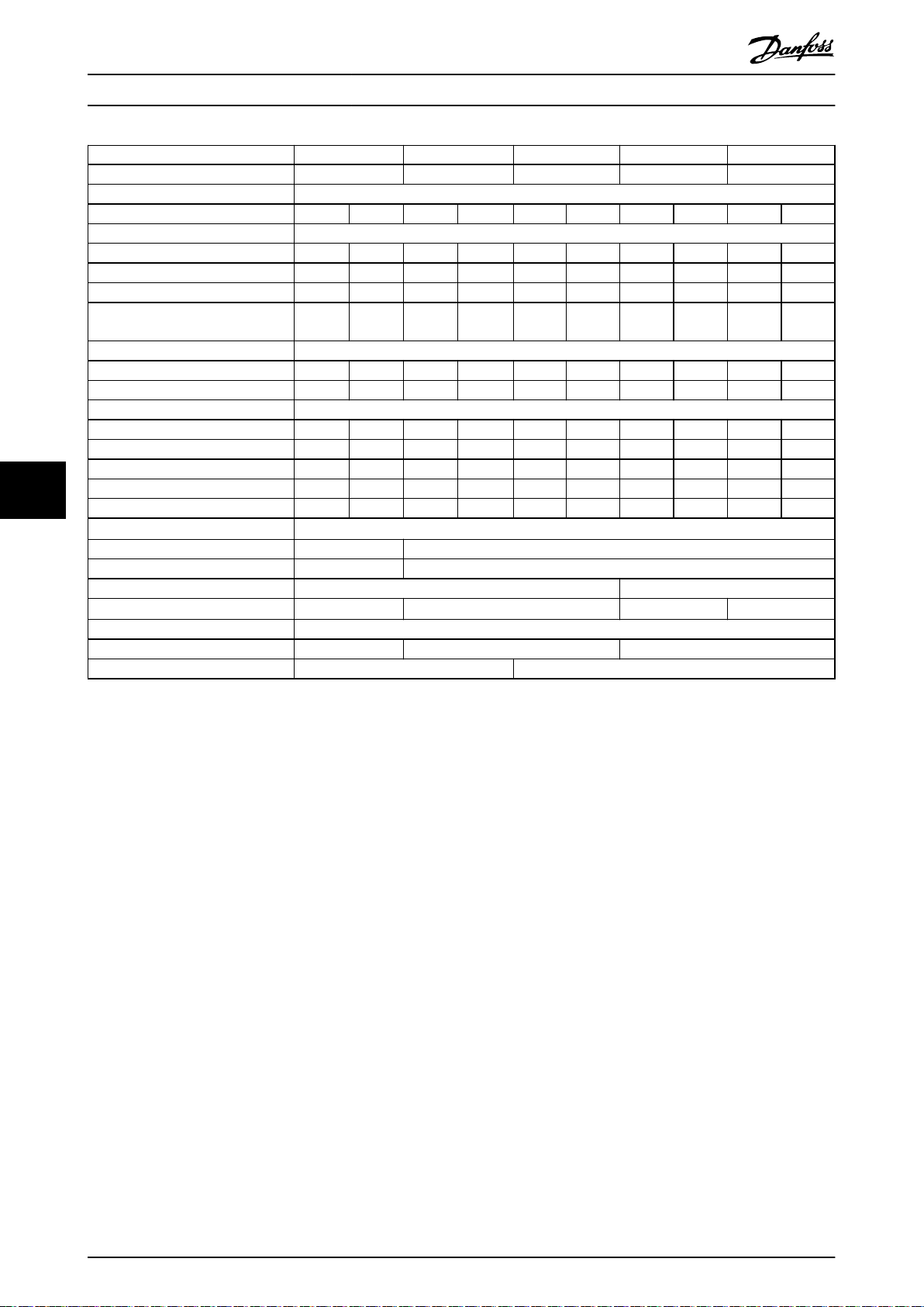
Specications
Power range N560 N630 N710 N800 N1M0
Drive modules 4 4 4 4 4
Rectier conguration 6-pulse/12-pulse
High/normal load HO NO HO NO HO NO HO NO HO NO
Output current [A]
Continuous (at 400 V) 880 990 990 1120 1120 1260 1260 1460 1460 1720
Intermittent (60 s overload) at 400 V 1320 1089 1485 1232 1680 1386 1890 1606 2190 1892
Continuous (at 460/500 V) 780 890 890 1050 1050 1160 1160 1380 1380 1530
Intermittent (60 s overload) at
460/500 V
Input current [A]
Continuous (at 400 V) 857 964 964 1090 1090 1227 1127 1422 1422 1675
Continuous (at 460 V) 759 867 867 1022 1022 1129 1129 1344 1344 1490
Power losses [W]
Drive modules at 400 V 7713 8810 8918 10199 10181 11632 11390 13253 13479 16463
Drive modules at 460 V 6641 7628 7855 9324 9316 10375 12391 12391 12376 13958
AC bus bars at 400 V 655 665 665 680 680 695 695 722 722 762
77
AC bus bars at 460 V 647 656 656 671 671 683 683 710 710 732
DC bus bars during regeneration 218 218 232 232 250 250 276 276 318 318
Maximum cable size [mm2 (mcm)]
Mains 4x185 (350) 8x125 (250)
Motor 4x185 (350) 8x125 (250)
Brake 8x70 (2/0) 8x95 (3/0)
Regeneration terminals
Maximum external mains fuses
6-pulse conguration 600 V, 1600 A 600 V, 2000 A 600 V, 2500 A
12-pulse conguration 600 V, 900 A 600 V, 1500 A
1)
VLT® Parallel Drive Modules
1170 979 1335 1155 1575 1276 1740 1518 2070 1683
6x125 (250)
8x125 (250) 8x150 (300) 10x150 (300)
Table 7.6 FC 202, 380–480 V AC Mains Supply (4-Drive System)
1) If Danfoss bus bar kit is used.
50 Danfoss A/S © 08/2017 All rights reserved. MG37K302

Specications Installation Guide
Power range N315 N400 N450
Drive modules 2 2 2
Rectier conguration 12-pulse
High/normal load HO NO HO NO HO NO
Output current [A]
Continuous (at 550 V) 303 360 360 418 395 470
Intermittent (60 s overload) at 550 V 455 396 560 460 593 517
Continuous (at 575/690 V) 290 344 344 400 380 450
Intermittent (60 s overload) at 575/690 V 435 378 516 440 570 495
Input current [A]
Continuous (at 550 V) 299 355 355 408 381 453
Continuous (at 575 V) 286 339 339 490 366 434
Continuous (at 690 V) 296 352 352 400 366 434
Power losses [W]
Drive modules at 575 V 3688 4401 4081 4789 4502 5457
Drive modules at 690 V 3669 4352 4020 4709 4447 5354
AC bus bars at 575 V 538 540 540 541 540 544
DC bus bars during regeneration 88 88 89 89 90 90
Maximum cable size [mm2 (mcm)]
Mains 2x120 (250) 4x120 (250)
Motor 2x120 (250) 4x120 (250)
Brake 4x70 (2/0)
Regeneration terminals
Maximum external mains fuses 700 V, 550 A
1)
4x120 (250)
7 7
Table 7.7 FC 202, 525–690 V AC Mains Supply (2-Drive System)
1) If Danfoss bus bar kit is used.
MG37K302 Danfoss A/S © 08/2017 All rights reserved. 51

Specications
Power range N500 N560 N630
Drive modules 2 2 2
Rectier conguration 12-pulse
High/normal load HO NO HO NO HO NO
Output current [A]
Continuous (at 550 V) 429 523 523 596 596 630
Intermittent (60 s overload) at 550 V 644 575 785 656 894 693
Continuous (at 575/690 V) 410 500 500 570 570 630
Intermittent (60 s overload) at 575/690 V 615 550 750 627 627 693
Input current [A]
Continuous (at 550 V) 413 504 504 574 574 607
Continuous (at 575 V) 395 482 482 549 549 607
Continuous (at 690 V) 395 482 482 549 549 607
Power losses [W]
Drive modules at 575 V 4892 6076 6016 6995 6941 7431
Drive modules at 690 V 4797 5951 5886 6831 6766 7638
AC bus bars at 575 V 542 546 546 550 550 553
77
DC bus bars during regeneration 91 91 186 186 191 191
Maximum cable size [mm2 (mcm)]
Mains 4x120 (250)
Motor 4x120 (250)
Brake 4x70 (2/0) 4x95 (3/0)
Regeneration terminals
Maximum external mains fuses 700 V, 630 A
1)
VLT® Parallel Drive Modules
4x120 (250)
Table 7.8 FC 202, 525–690 V AC Mains Supply (2-Drive System)
1) If Danfoss bus bar kit is used.
52 Danfoss A/S © 08/2017 All rights reserved. MG37K302

Specications Installation Guide
Power range N710 N800 N900 N1M0 N1M2
Drive modules 4 4 4 4 4
Rectier conguration 6-pulse/12-pulse
High/normal load HO NO HO NO HO NO HO NO HO NO
Output current [A]
Continuous (at 550 V) 659 763 763 889 889 988 988 1108 1108 1317
Intermittent (60 s overload) at 550 V 989 839 1145 978 1334 1087 1482 1219 1662 1449
Continuous (at 575/690 V) 630 730 730 850 850 945 945 1060 1060 1260
Intermittent (60 s overload) at
575/690 V
Input current [A]
Continuous (at 550 V) 642 743 743 866 866 962 1079 1079 1079 1282
Continuous (at 575 V) 613 711 711 828 828 920 1032 1032 1032 1227
Continuous (at 690 V) 613 711 711 828 828 920 1032 1032 1032 1227
Power losses [W]
Drive modules at 575 V 7469 8683 8668 10166 10163 11406 11292 12852 12835 15762
Drive modules at 690 V 7381 8559 8555 9996 9987 11188 11077 12580 12551 15358
AC bus bars at 575 V 637 644 644 653 653 661 661 672 672 695
DC bus bars during regeneration 198 198 208 208 218 218 231 231 256 256
Maximum cable size [mm2 (mcm)]
Mains 4x120 (250) 6x120 (250) 8x120 (250)
Motor 4x120 (250) 6x120 (250) 8x120 (250)
Brake 8x70 (2/0) 8x95 (3/0)
Regeneration terminals
Maximum external mains fuses
6-pulse conguration 700 V, 1600 A 700 V, 2000 A
12-pulse conguration 700 V, 900 A 700 V, 1500 A
1)
945 803 1095 935 1275 1040 1418 1166 1590 1590
4x150 (300)
6x120 (250) 6x150 (300) 8x120 (250)
7 7
Table 7.9 FC 202, 525–690 V AC Mains Supply (4-Drive System)
1) If Danfoss bus bar kit is used.
MG37K302 Danfoss A/S © 08/2017 All rights reserved. 53

Specications
7.1.3
VLT® AutomationDrive FC 302
Power range N250 N315 N355 N400 N450
Drive modules 2 2 2 2 2
Rectier conguration 12-pulse 6-pulse/12-pulse
High/normal load HO NO HO NO HO NO HO NO HO NO
Output current [A]
Continuous (at 380–440 V) 480 588 600 658 658 745 695 800 810 880
Intermittent (60 s overload) at 400 V 720 647 900 724 987 820 1043 880 1215 968
Continuous (at 460/500 V) 443 535 540 590 590 678 678 730 730 780
Intermittent (60 s overload) at
460/500 V
Input current [A]
Continuous (at 400 V) 463 567 590 647 647 733 684 787 779 857
Continuous (at 460/500 V) 427 516 531 580 580 667 667 718 711 759
Power losses [W]
Drive modules at 400 V 4505 5825 5502 6110 6110 7069 6375 7538 7526 8468
77
Drive modules at 460 V 4063 4998 5384 5964 5721 6175 6070 6609 6604 7140
AC bus bars at 400 V 545 550 551 555 555 561 557 565 566 575
AC bus bars at 460 V 543 548 548 551 556 556 556 560 560 563
Maximum cable size [mm2 (mcm)]
Mains 4x120 (250) 4x150 (300)
Motor 4x120 (250) 4x150 (300)
Brake 4x70 (2/0) 4x95 (3/0)
Regeneration terminals
Maximum external mains fuses
6-pulse conguration – – – – 600 V, 1600 A
12-pulse conguration 600 V, 700 A 600 V, 900 A
1)
VLT® Parallel Drive Modules
665 588 810 649 885 746 1017 803 1095 858
4x120 (250) 4x150 (300) 6x120 (250)
Table 7.10 FC 302, 380–500 V AC Mains Supply (2-Drive System)
1) If Danfoss bus bar kit is used.
54 Danfoss A/S © 08/2017 All rights reserved. MG37K302

Specications Installation Guide
Power range N500 N560 N630 N710 N800
Drive modules 4 4 4 4 4
Rectier conguration 6-pulse/12-pulse
High/normal load HO NO HO NO HO NO HO NO HO NO
Output current [A]
Continuous (at 380–440 V) 880 990 990 1120 1120 1260 1260 1460 1460 1720
Intermittent (60 s overload) at 400 V 1320 1089 1485 1232 1680 1386 1890 1606 2190 1892
Continuous (at 460/500 V) 780 890 890 1050 1050 1160 1160 1380 1380 1530
Intermittent (60 s overload) at 460/500 V 1170 979 1335 1155 1575 1276 1740 1518 2070 1683
Input current [A]
Continuous (at 400 V) 857 964 964 1090 1090 1227 1227 1422 1422 1675
Continuous (at 460/500 V) 759 867 867 1022 1022 1129 1129 1344 1344 1490
Power losses [W]
Drive modules at 400 V 7713 8810 8918 10199 10181 11632 11390 13253 13479 16463
Drive modules at 460 V 6641 7628 7855 9324 9316 10375 12391 12391 12376 13958
AC bus bars at 400 V 655 665 665 680 680 695 695 722 722 762
AC bus bars at 460 V 647 656 656 671 671 683 683 710 710 732
DC bus bars during regeneration 218 218 232 232 250 276 276 276 318 318
Maximum cable size [mm2 (mcm)]
Mains 4x185 (350) 8x120 (250)
Motor 4x185 (350) 8x120 (250)
Brake 8x70 (2/0) 8x95 (3/0)
Regeneration terminals
Maximum external mains fuses
6-pulse conguration 600 V, 1600 A 600 V, 2000 A 600 V, 2500 A
12-pulse conguration 600 V, 900 A 600 V, 1500 A
1)
6x125 (250) 8x125 (250) 8x150 (300) 10x150 (300)
7 7
Table 7.11 FC 302, 380–500 V AC Mains Supply (4-Drive System)
1) If Danfoss bus bar kit is used.
MG37K302 Danfoss A/S © 08/2017 All rights reserved. 55

Specications
Power range N250 N315 N355 N400
Drive modules 2 2 2 2
Rectier conguration 12-pulse
High/normal load HO NO HO NO HO NO HO NO
Output current [A]
Continuous (at 550 V) 303 360 360 418 395 470 429 523
Intermittent (60 s overload) at 550 V 455 396 560 360 593 517 644 575
Continuous (at 575/690 V) 290 344 344 400 380 450 410 500
Intermittent (60 s overload) at 575/690 V 435 378 516 440 570 495 615 550
Input current [A]
Continuous (at 550 V) 299 355 355 408 381 453 413 504
Continuous (at 575 V) 286 339 339 490 366 434 395 482
Continuous (at 690 V) 296 352 352 400 366 434 395 482
Power losses [W]
Drive modules at 600 V 3688 4401 4081 4789 4502 5457 4892 6076
Drive modules at 690 V 3669 4352 4020 4709 4447 5354 4797 5951
AC bus bars at 575 V 538 540 540 541 540 544 542 546
77
DC bus bars during regeneration 88 88 89 89 90 90 91 91
Maximum cable size [mm2 (mcm)]
Mains 2x120 (250) 4x120 (250)
Motor 2x120 (250) 4x120 (250)
Brake 4x70 (2/0)
Regeneration terminals
Maximum external mains fuses 700 V, 550 A
1)
VLT® Parallel Drive Modules
4x120 (250)
Table 7.12 FC 302, 525–690 V AC Mains Supply (2-Drive System)
1) If Danfoss bus bar kit is used.
56 Danfoss A/S © 08/2017 All rights reserved. MG37K302
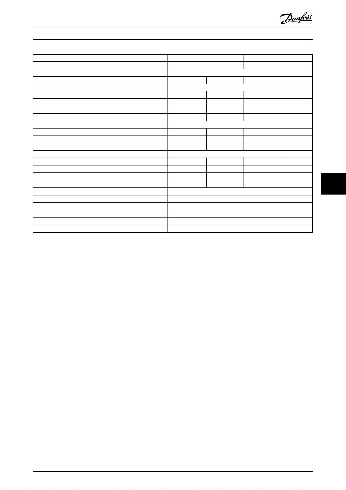
Specications Installation Guide
Power range N500 N560
Drive modules 2 2
Rectier conguration 12-pulse
High/normal load HO NO HO NO
Output current [A]
Continuous (at 550 V) 523 596 596 630
Intermittent (60 s overload) at 550 V 785 656 894 693
Continuous (at 575/690 V) 500 570 570 630
Intermittent (60 s overload) at 575/690 V 750 627 627 693
Input current [A]
Continuous (at 550 V) 504 574 574 607
Continuous (at 575 V) 482 549 549 607
Continuous (at 690 V) 482 549 549 607
Power losses [W]
Drive modules at 600 V 6016 6995 6941 7431
Drive modules at 690 V 5886 6831 6766 7638
AC bus bars at 575 V 546 550 550 553
DC bus bars during regeneration 186 186 191 191
Maximum cable size [mm2 (mcm)]
Mains 4x120 (250)
Motor 4x120 (250)
Brake 4x95 (3/0)
Regeneration terminals
Maximum external mains fuses 700 V, 630 A
1)
4x120 (250)
7 7
Table 7.13 FC 302, 525–690 V AC Mains Supply (2-Drive System)
1) If Danfoss bus bar kit is used.
MG37K302 Danfoss A/S © 08/2017 All rights reserved. 57

Specications
Power range N630 N710 N800 N900 N1M0
Drive modules 4 4 4 4 4
Rectier conguration 6-pulse/12-pulse
High/normal load HO NO HO NO HO NO HO NO HO NO
Output current [A]
Continuous (at 550 V) 659 763 763 889 889 988 988 1108 1108 1317
Intermittent (60 s overload) at 550 V 989 839 1145 978 1334 1087 1482 1219 1662 1449
Continuous (at 575/690 V) 630 730 730 850 850 945 945 1060 1060 1260
Intermittent (60 s overload) at
575/690 V
Input current [A]
Continuous (at 550 V) 642 743 743 866 866 962 1079 1079 1079 1282
Continuous (at 575 V) 613 711 711 828 828 920 1032 1032 1032 1227
Continuous (at 690 V) 613 711 711 828 828 920 1032 1032 1032 1227
Power losses [W]
Drive modules at 600 V 7469 8683 8668 10166 10163 11406 11292 12852 12835 15762
Drive modules at 690 V 7381 8559 8555 9996 9987 11188 11077 12580 12551 15358
77
AC bus bars at 575 V 637 644 644 653 653 661 661 672 672 695
DC bus bars during regeneration 198 198 208 208 218 218 231 231 256 256
Maximum cable size [mm2 (mcm)]
Mains 4x120 (250) 6x120 (250) 8x120 (250)
Motor 4x120 (250) 6x120 (250) 8x120 (250)
Brake 8x70 (2/0) 8x95 (3/0)
Regeneration terminals
Maximum external mains fuses
6-pulse conguration 700 V, 1600 A 700 V, 2000 A
12-pulse conguration 700 V, 900 A 700 V, 1500 A
1)
VLT® Parallel Drive Modules
945 803 1095 935 1275 1040 1418 1166 1590 1590
4x150 (300) 6x120 (250)
6x150 (300)
8x120 (250)
Table 7.14 FC 302, 525–690 V AC Mains Supply (4-Drive System)
1) If Danfoss bus bar kit is used.
58 Danfoss A/S © 08/2017 All rights reserved. MG37K302

Specications Installation Guide
7.2 Mains Supply to Drive Module
Mains supply
Supply terminals R/91, S/92, T/93
Supply voltage
Supply frequency 50/60 Hz ±5%
Maximum temporary imbalance between mains phases 3.0% of rated supply voltage
True power factor (λ) ≥0.98 nominal at rated load
Displacement power factor (cos Φ) (Approximately 1)
Switching on input supply L1, L2, L3 Maximum 1 time per 2 minutes
Environment according to EN 60664-1 Overvoltage category III/pollution degree 2
1) The unit is suitable for use on a circuit capable of delivering not more than 85000 RMS symmetrical Amperes, 480/600 V.
2) Mains voltage low/mains voltage drop-out:
During low mains voltage, the drive module continues until the DC-link voltage drops below the minimum stop level, which
corresponds typically to 15% below the lowest rated supply voltage. Power-up and full torque cannot be expected at mains
voltage lower than 10% below the lowest rated supply voltage. The drive module trips for a detected mains drop-out.
1)
2)
380–480, 500 V 690 V, ±10%, 525–690 V ±10%
7.3 Motor Output and Motor Data
Motor output
Motor terminals U/96, V/97, W/98
Output voltage 0–100% of supply voltage
Output frequency 0–590 Hz
Switching on output Unlimited
Ramp times 1–3600 s
7 7
Torque characteristics
Overload torque (constant torque) Maximum 150% for 60 s
Starting torque Maximum 180% up to 0.5 s
Overload torque (variable torque) Maximum 110% for s
Starting torque (variable torque) Maximum 135% for s
1) Percentage relates to the nominal torque.
Eciency
Eciency
1) Eciency measured at nominal current. For energy eciency class, see . For part load losses, see www.danfoss.com/vltener-
gyeciency.
98%
7.4 12-Pulse Transformer Specications
Connection Dy11 d0 or Dyn 11d0
Phase shift between secondaries 30°
Voltage dierence between secondaries <0.5%
Short circuit impedance of secondaries >5%
Short circuit impedance dierence between secondaries <5% of short circuit impedance
Other No grounding of the secondaries allowed. Static shield recommended
7.5 Ambient Conditions for Drive Modules
1)
1)
1)
1)
Environment
IP rating IP00
Acoustic noise 84 dB (running at full load)
Vibration test 1.0 g
Vibration and shock (IEC 60721-33-3) Class 3M3
Maximum relative humidity 5–95% (IEC 721–3–3; Class 3K3 (non-condensing)) during operation
MG37K302 Danfoss A/S © 08/2017 All rights reserved. 59

Specications
Aggressive environment (IEC 60068-2-43) H2S test Class Kd
Aggressive gases (IEC 60721-3-3) Class 3C3
Ambient temperature
Minimum ambient temperature during full-scale operation 0 °C (32 °F)
Minimum ambient temperature at reduced performance -10 °C (14 °F)
Temperature during storage/transport -25 to +65 °C (-13 to 149 °F)
Maximum altitude above sea level without derating
EMC standards, Emission EN 61800-3
EMC standards, Immunity EN 61800-4-2, EN 61800-4-3, EN 61800-4-4, EN 61800-4-5, and EN 61800-4-6
Energy eciency class
1) Refer to the VLT® Parallel Drive Modules Design Guide for derating for high ambient temperature and derating for high
altitude.
2) Determined according to EN 50598-2 at:
Rated load.
•
90% rated frequency.
•
Switching frequency factory setting.
•
77
Switching pattern factory setting.
•
1)
2)
VLT® Parallel Drive Modules
Maximum 45 °C (113 °F) (24-hour average maximum 40 °C (104 °F))
1)
1000 m (3281 ft)
IE2
7.6 Cable Specications
Cable lengths and cross-sections for control cables
Maximum motor cable length, shielded 150 m (492 ft)
Maximum motor cable length, unshielded 300 m (984 ft)
Maximum cross-section to control terminals, exible or rigid wire without cable end sleeves 1.5 mm2/16 AWG
Maximum cross-section to control terminals, exible wire with cable end sleeves 1 mm2/18 AWG
Maximum cross-section to control terminals, exible wire with cable end sleeves with collar 0.5 mm2/20 AWG
Minimum cross-section to control terminals 0.25 mm2/24 AWG
Maximum cross-section to 230 V terminals 2.5 mm2/14 AWG
Minimum cross-section to 230 V terminals 0.25 mm2/24 AWG
1) For power cables, see electrical data tables in chapter 7.1 Power-dependent Specications.
1)
7.7 Control Input/Output and Control Data
Digital inputs
Programmable digital inputs
Terminal number 18, 19, 271), 291), 32, 33
Logic PNP or NPN
Voltage level 0–24 V DC
Voltage level, logic 0 PNP <5 V DC
Voltage level, logic 1 PNP >10 V DC
Voltage level, logic 0 NPN
Voltage level, logic 1 NPN
Maximum voltage on input 28 V DC
Pulse frequency range 0–110 kHz
(Duty cycle) Minimum pulse width 4.5 ms
Input resistance, R
All digital inputs are galvanically isolated from the supply voltage (PELV) and other high voltage terminals.
1) Terminals 27 and 29 can also be programmed as output.
2) Except Safe Torque O input terminal 37.
2)
2)
i
Approximately 4 kΩ
4 (6)
>19 V DC
<14 V DC
1)
60 Danfoss A/S © 08/2017 All rights reserved. MG37K302

Mains
Functional
isolation
PELV isolation
Motor
DC-bus
High
voltage
Control
+24 V
RS485
18
37
130BA117.10
Specications Installation Guide
Safe Torque O (STO) Terminal 37
1), 2)
(Terminal 37 is xed PNP logic)
Voltage level 0–24 V DC
Voltage level, logic 0 PNP <4 V DC
Voltage level, logic 1 PNP >20 V DC
Maximum voltage on input 28 V DC
Typical input current at 24 V 50 mA
Typical input current at 20 V 60 mA
rms
rms
Input capacitance 400 nF
All digital inputs are galvanically isolated from the supply voltage (PELV) and other high voltage terminals.
®
1) See VLT
Frequency Converters – Safe Torque O Operating Guide for further information about terminal 37 and Safe Torque
O.
2) When using a contactor with a DC coil with STO, always make a return path for the current from the coil when turning it o.
The return path can be made by using a freewheel diode across the coil. Alternatively, use a 30 V or 50 V MOV for quicker
response time. Typical contactors can be bought with this diode.
Analog inputs
Number of analog inputs 2
Terminal number 53, 54
Modes Voltage or current
Mode select Switch S201 and switch S202
Voltage mode Switch S201/switch S202 = OFF (U)
Voltage level -10 V to +10 V (scalable)
Input resistance, R
i
Approximately 10 kΩ
Maximum voltage ±20 V
Current mode Switch S201/switch S202 = ON (I)
Current level 0/4–20 mA (scalable)
Input resistance, R
i
Approximately 200 Ω
Maximum current 30 mA
Resolution for analog inputs 10 bit (+ sign)
Accuracy of analog inputs Maximum error 0.5% of full scale
Bandwidth 20 Hz/100 Hz
The analog inputs are galvanically isolated from the supply voltage (PELV) and other high voltage terminals.
7 7
Illustration 7.1 PELV Isolation
Pulse input
Programmable pulse 2/1
Terminal number pulse 291), 32/33
Maximum frequency at terminal 29, 33 110 kHz (Push-pull driven)
Maximum frequency at terminal 29, 33 5 kHz (open collector)
Minimum frequency at terminal 29, 33 4 Hz
Voltage level 0–24 V DC
Maximum voltage on input 28 V DC
Input resistance, R
Pulse input accuracy (0.1–1 kHz) Maximum error: 0.1% of full scale
MG37K302 Danfoss A/S © 08/2017 All rights reserved. 61
i
Approximately 4 kΩ

Specications
Encoder input accuracy (1–11 kHz) Maximum error: 0.05% of full scale
The pulse and encoder inputs (terminals 29, 32, 33) are galvanically isolated from the supply voltage (PELV) and other high
voltage terminals.
1) Pulse inputs are 29 and 33.
Analog output
Number of programmable analog outputs 1
Terminal number 42
Current range at analog output 0/4–20 mA
Maximum load GND - analog output 500 Ω
Accuracy on analog output Maximum error: 0.5% of full scale
Resolution on analog output 12 bit
The analog output is galvanically isolated from the supply voltage (PELV) and other high voltage terminals.
Control card, RS485 serial communication
Terminal number 68 (P, TX+, RX+), 69 (N, TX-, RX-)
Terminal number 61 Common for terminals 68 and 69
77
The RS485 serial communication circuit is functionally separated from other central circuits and galvanically isolated from the
supply voltage (PELV ).
Digital output
Programmable digital/pulse outputs 2
Terminal number 27, 29
Voltage level at digital/frequency output 0–24 V
Maximum output current (sink or source) 40 mA
Maximum load at frequency output 1 kΩ
Maximum capacitive load at frequency output 10 nF
Minimum output frequency at frequency output 0 Hz
Maximum output frequency at frequency output 32 kHz
Accuracy of frequency output Maximum error: 0.1% of full scale
Resolution of frequency outputs 12 bit
1) Terminals 27 and 29 can also be programmed as input.
The digital output is galvanically isolated from the supply voltage (PELV) and other high voltage terminals.
VLT® Parallel Drive Modules
1)
Control card, 24 V DC output
Terminal number 12, 13
Output voltage 24 V +1, -3 V
Maximum load 200 mA
The 24 V DC supply is galvanically isolated from the supply voltage (PELV ), but has the same potential as the analog and digital
inputs and outputs.
Relay outputs
Programmable relay outputs 2
Relay 01 terminal number 1–3 (break), 1–2 (make)
Maximum terminal load (AC-1)1) on 1–3 (NC), 1–2 (NO) (resistive load) 240 V AC, 2 A
Maximum terminal load (AC-15)1) (inductive load @ cosφ 0.4) 240 V AC, 0.2 A
Maximum terminal load (DC-1)1) on 1–2 (NO), 1–3 (NC) (resistive load) 60 V DC, 1 A
Maximum terminal load (DC-13)1) (inductive load) 24 V DC, 0.1 A
Relay 02 (VLT® AutomationDrive FC 302 only) terminal number 4–6 (break), 4–5 (make)
Maximum terminal load (AC-1)1) on 4–5 (NO) (resistive load)
Maximum terminal load (AC-15)1) on 4–5 (NO) (inductive load @ cosφ 0.4) 240 V AC, 0.2 A
Maximum terminal load (DC-1)1) on 4–5 (NO) (resistive load) 80 V DC, 2 A
Maximum terminal load (DC-13)1) on 4–5 (NO) (inductive load) 24 V DC, 0.1 A
Maximum terminal load (AC-1)1) on 4–6 (NC) (resistive load) 240 V AC, 2 A
Maximum terminal load (AC-15)1) on 4–6 (NC) (inductive load @ cosφ 0.4) 240 V AC, 0.2 A
Maximum terminal load (DC-1)1) on 4–6 (NC) (resistive load) 50 V DC, 2 A
2)3)
overvoltage category II 400 V AC, 2 A
62 Danfoss A/S © 08/2017 All rights reserved. MG37K302

Specications Installation Guide
Maximum terminal load (DC-13)1) on 4–6 (NC) (inductive load) 24 V DC, 0.1 A
Minimum terminal load on 1–3 (NC), 1–2 (NO), 4–6 (NC), 4–5 (NO) 24 V DC 10 mA, 24 V AC 20 mA
Environment according to EN 60664-1 Overvoltage category III/pollution degree 2
1) IEC 60947 part 4 and 5.
The relay contacts are galvanically isolated from the rest of the circuit by reinforced isolation (PELV).
2) Overvoltage Category II.
3) UL applications 300 V AC 2A.
Control card, 10 V DC output
Terminal number 50
Output voltage 10.5 V ±0.5 V
Maximum load 25 mA
The 10 V DC supply is galvanically isolated from the supply voltage (PELV ) and other high voltage terminals.
Control characteristics
Resolution of output frequency at 0–590 Hz ±0.003 Hz
Repeat accuracy of precise start/stop (terminals 18, 19) ≤±0.1 ms
System response time (terminals 18, 19, 27, 29, 32, 33) ≤10 ms
Speed control range (open loop) 1:100 of synchronous speed
Speed control range (closed loop) 1:1000 of synchronous speed
Speed accuracy (open loop) 30–4000 RPM: Error ±8 RPM
Speed accuracy (closed loop), depending on resolution of feedback device 0–6000 RPM: Error ±0.15 RPM
All control characteristics are based on a 4-pole asynchronous motor
7 7
Control card performance
®
Scan interval (VLT
Drive FC 202) 5 ms (VLT® AutomationDrive FC 302)
Scan interval (FC 302) 1 ms
Control card, USB serial communication
USB standard 1.1 (full speed)
USB plug USB type B device plug
Connection to PC is carried out via a standard host/device USB cable.
The USB connection is galvanically isolated from the supply voltage (PELV) and other high voltage terminals.
The USB ground connection is NOT galvanically isolated from protective earth. Use only an isolated laptop as PC connection to
the USB connector on the frequency converter.
HVAC Drive FC 102, VLT® Refrigeration Drive FC 103, VLT® AQUA
MG37K302 Danfoss A/S © 08/2017 All rights reserved. 63

346
(13.6)
868
[34.2]
856.6
(33.7)
1051
(41.4)
1096
(43.1)
1122
(44.2)
130
(5.1)
41
(1.6)
1048
(41.3)
280
(11.0)
107
(4.2)
213
(8.4)
320
(12.6)
271
(10.7)
95
(3.7)
130BE654.11
376
(14.8)
Specications
VLT® Parallel Drive Modules
7.8 Kit Dimensions
7.8.1 Exterior Dimensions
Illustration 7.2 shows the dimensions of the drive module related to its installation.
77
Illustration 7.2 VLT® Parallel Drive Modules Installation Dimensions
Description Module weight [kg (lb)] Length x width x depth [mm (in)]
Drive module 125 (275) 1121.7 x 346.2 x 375 (44.2 x 13.6 x 14.8)
Table 7.15 Drive Module Weight and Dimensions
64 Danfoss A/S © 08/2017 All rights reserved. MG37K302

A
A
B
B
R
S
T
U
V
W
130BE748.10
319 (12.6)
200 (7.9)
0 (0.0)
376 (14.8)
Brake terminals
236.8 (9.0)
293 (11.5)
0 (0.0)
33 (1.3)
91 (3.6)
149 (5.8)
211 (8.3)
319 (12.6)
265 (10.4)
130BE749.10
Section A-A
Mains Terminals
Section B-B
Motor and Brake Terminals
Brake terminal
Motor terminal
Mains terminal
284 (11.2)
0 (0.0)
0 (0.0)
306 (12.1)
255 (10.0)
Specications Installation Guide
7.8.2 Terminal Dimensions
7 7
Illustration 7.3 Drive Module Terminal Dimensions (Front View)
Illustration 7.4 Drive Module Terminal Dimensions (Side Views)
MG37K302 Danfoss A/S © 08/2017 All rights reserved. 65

130BE751.10
105.5
(4.15)
236
(9.3)
126
(4.9)
95
(3.7)
Specications
VLT® Parallel Drive Modules
7.8.3 DC Bus Dimensions
77
Illustration 7.5 DC Bus Dimensions (Front and Side Views)
7.9 Fastener Tightening Torques
For fastening hardware described in this manual, use the torque values in Table 7.16. These torque values are not intended
for fastening IGBTs. See the instructions included with those replacement parts for the correct torque values.
Shaft size Driver size Torx/hex Torque (N · m) Torque (in-lb)
M4 T20 Torx/7 mm hex 1.0 9
M5 T25 Torx/8 mm hex 2.3 20
M6 T30 Torx/10 mm hex 4.0 35
M8 T40 Torx/13 mm hex 9.6 85
M10 T50 Torx/17 mm hex 19.1 169
M12 (hex bolts only) 18 mm or 19 mm hex 19.1 169
Table 7.16 General Tightening Torques of Fasteners
7.9.1 Tightening Torques for Terminals
For fastening terminals, use the torque values in Table 7.17.
Mains Motor Regen Load sharing Ground Brake
Bolt size
Torque [N · m
(in-lb)]
M10 M10 M10 M10 M8 M8
19–40 (168–354) 19–40 (168–354) 19–40 (168–354) 19–40 (168–354)
8.5–20.5
(75–181)
8.5–20.5 (75–181)
Table 7.17 Tightening of Terminals
66 Danfoss A/S © 08/2017 All rights reserved. MG37K302

Appendix Installation Guide
8 Appendix
8.1 Disclaimer
Danfoss shall have no obligation with respect to any
product that
is not installed according to the standard congu-
•
ration as specied in the installation guide.
is improperly repaired or altered.
•
is subjected to misuse, negligence, and improper
•
installation where the guidelines were not
followed.
is used in a contradictory manner to the
•
instructions provided.
is a result of normal wear and tear.
•
8.2 Symbols, Abbreviations, and
Conventions
Degrees Celsius
°C
Degrees Fahrenheit
°F
AC Alternating current
AWG American wire gauge
DC Direct current
EMC Electro magnetic compatibility
ETR Electronic thermal relay
FC Frequency converter
IP Ingress protection
LCP Local control panel
MCT Motion control tool
MDCI
Multi-drive control interface
C
PCB Printed circuit board
PELV Protective extra low voltage
PM
Permanent magnet motor
Motor
RCD Residual current-operated protective device
Regen Regenerative terminals
RFI Radio frequency interference
RPM Revolutions per minute
Conventions
Numbered lists indicate procedures.
Bullet lists indicate other information and description of
illustrations.
Italicized text indicates:
Cross-references.
•
Links.
•
Parameter names.
•
All measurements are given in both metric units and
imperial units. Imperial units are in ( ).
8 8
Table 8.1 Symbols and Abbreviations
MG37K302 Danfoss A/S © 08/2017 All rights reserved. 67

130BE734.10
1
2
3
5
6
7
4
8
9
10
Appendix
VLT® Parallel Drive Modules
8.3 Block Diagrams
8.3.1 Connection of 12-Pulse Disconnector/Interlock
88
1 Drive module 1 6 Disconnector 1
2 Drive module 2 7 Brake fault
3 Supplementary fuses 8 Drive module 3
4 Mains input bus bars 9 Drive module 4
5 Brake fault 10 Disconnector 2
Illustration 8.1 Connection of 12-Pulse Disconnector/Interlock
68 Danfoss A/S © 08/2017 All rights reserved. MG37K302

1
2
1 2 1 28 7 6 11 10 9
2
11
2
44
43
DC+ DC-MK102
130BE735.10
1
2
3
4
Appendix Installation Guide
8.3.2 BRF Connection with 12-Pulse Disconnector/Interlock
1 Auxiliary contact disconnector 1 3 Klixon switch
2 Auxiliary contact disconnector 2 4 BRF connector
8 8
Illustration 8.2 BRF Connection with 12-Pulse Disconnector/Interlock
MG37K302 Danfoss A/S © 08/2017 All rights reserved. 69

1
2
1 2 1 28 7 6 11 10 9
2
11
2
44
43
DC+ DC-MK102
130BE736.10
1
2
Appendix
8.3.3 BRF Jumper Connection
VLT® Parallel Drive Modules
88
1 BRF jumper (pre-installed) 2 BRF connector
Illustration 8.3 BRF Jumper Connection
70 Danfoss A/S © 08/2017 All rights reserved. MG37K302

2
1
130BE737.11
1
2
3
R/91S/92T/93U/96V/97W/98R+R -R/91S/92T/93U/96V/97W/98R+R
-
R/91S/92T/93U/96V/97W/98R+R -R/91S/92T/93U/96V/97W/98R+R
-
Appendix Installation Guide
8.3.4 Connection of Common Brake Resistor
8 8
1 Drive module 3 Common brake resistor
2 Brake terminals – –
Illustration 8.4 Connection of Common Brake Resistor
MG37K302 Danfoss A/S © 08/2017 All rights reserved. 71

130BE738.10
1
2
1 2 1 28 7 6 11 10 9
2
11
2
44
43
DC+ DC-MK102
1
2
3
Appendix
8.3.5 Klixon Switch Connection
VLT® Parallel Drive Modules
88
1 Klixon switch 3 Ferrite core
2 BRF connector – –
Illustration 8.5 Klixon Switch Connection
72 Danfoss A/S © 08/2017 All rights reserved. MG37K302

130BE739.10
FC–X02
1
1
1
1
1
1 2 3 4 5 6 7 8 910
2
2
3455 6
6
1
2
5
6
123456
2
2
2
43 44
4344
43
44
1
2
43
44
1
2
43
44
1
2
43
44
FK100
MK100
MK115
MK106
MK111
MK112 MK114
MK113
MK107
MK108
MK109
MK110
FK101
INV1 INV2 INV3 INV4
L
AC
DC
N
230V
12
9
10
11
13 14
1
2 5
3
4
6
7
8
Appendix Installation Guide
8.3.6 Control Shelf Connections
8 8
1 LCP cradle 8 Terminal block
2 Ribbon cable from LCP to MDCIC 9 Cable to remote-mounted LCP
3 44-pin cable to the drive module 1 (at MK 111) 10 Analog I/O terminals
4 44-pin cable to the drive module 3 (at MK 113) 11 Digital input terminals
5 Current scaling card 12 44-pin cable to the drive module 2 (at MK 112)
6 STO connector 13 44-pin cable to the drive module 4 (at MK 114)
7 STO relay 14 Ferrite cores
Illustration 8.6 Control Shelf Connections
MG37K302 Danfoss A/S © 08/2017 All rights reserved. 73

130BE740.10
R S T U V W R+ R- R S T U V W R+ R- R S T U V W R+ R- R S T U V W R+ R-
BASE
DRIVE
BASE
DRIVE
BASE
DRIVE
BASE
DRIVE
3
4
1
2
Appendix
VLT® Parallel Drive Modules
8.3.7 Discharge Resistor Connections
88
1 Mains input bus bars 3 Discharge resistor
2 Mains contactor/disconnector auxiliary contacts 4 Discharge contactor
Illustration 8.7 Discharge Resistor Connections
74 Danfoss A/S © 08/2017 All rights reserved. MG37K302

21 21 21 21
1
2
3
R/91S/92T/93U/96V/97W/98R+R -R/91S/92T/93U/96V/97W/98R+R
-
R/91S/92T/93U/96V/97W/98R+R -R/91S/92T/93U/96V/97W/98R+R
-
130BE741.11
Appendix Installation Guide
8.3.8 Connection of Individual Brake Resistor to Each Drive Module
8 8
1 Drive module 3 Individual brake resistors
2 Brake terminals – –
Illustration 8.8 Connection of Individual Brake Resistor to Each Drive Module
MG37K302 Danfoss A/S © 08/2017 All rights reserved. 75

e30be742.11
R/91S/92T/
93
U/96V/97W/98R+R
-
R/91S/92T/93U/96V/97W/98R+R
-
5
6
7
8
1
2
3
4
9
Appendix
VLT® Parallel Drive Modules
8.3.9 Connections in a 6-Pulse 2-Drive Module System
88
1 DC fuses 6 DC terminals
2 Drive module 7 Connection to brake
3 Mains input bus bars connecting both drive modules 8 Motor output bus bars connecting both drive modules
4 Connection to mains 9 Connection to motor output
5 DC-link bus bars connecting both drive modules – –
Illustration 8.9 Connections in a 6-Pulse 2-Drive Module System
76 Danfoss A/S © 08/2017 All rights reserved. MG37K302

e30be743.11
1
2
3
4
5
6
7
8
R/91S/92T/
93
U/96V/97W/98R+R
-
R/91S/92T/
93
U/96V/97W/98R+R
-
Appendix Installation Guide
8.3.10 Connections in a 12-Pulse 2-Drive Module System
8 8
1 DC fuses 5 DC-link bus bars connecting both drive modules
2 Drive module 6 DC terminals
3 Motor output bus bars connecting both drive
4 Connection to mains input 8 Connection to motor output
modules
7 Connection to brake
Illustration 8.10 Connections in a 12-Pulse 2-Drive Module System
MG37K302 Danfoss A/S © 08/2017 All rights reserved. 77

e30be744.11
R/91S/92T/93U/96V/97W/98R+R -R/91S/92T/93U/96V/97W/98R+R -R/91S/92T/93U/96V/97W/98R+R -R/91S/92T/93U/96V/97W/98R+R
-
1
2
3
4
5
6
7
8
9
Appendix
VLT® Parallel Drive Modules
8.3.11 Connections in a 4-Drive Module System
88
1 DC fuses 6 DC terminals
2 Drive module 7 Connection to brake
3 Mains input bus bars connecting 2 drive modules 8 Motor output bus bars connecting 2 drive modules
4 Connection to mains input 9 Connection to motor output
5 DC-link bus bars connecting all 4 drive modules – –
Illustration 8.11 Connections in a 4-Drive Module System
NOTICE
DRIVE MODULE WIRING
The installer must install an equal number of wires to
each set of drive modules.
78 Danfoss A/S © 08/2017 All rights reserved. MG37K302

Index Installation Guide
Index
A
A53 switch............................................................................................... 35
A54 switch............................................................................................... 35
Abbreviations......................................................................................... 67
AC mains............................................................................................. 7, 28
AC waveform............................................................................................ 7
Approvals................................................................................................... 4
B
Bus termination switch....................................................................... 35
Busbars..................................................................................................... 14
C
Cable
Clamp................................................................................................... 37
Control................................................................................... 37, 39, 40
Equalizing........................................................................................... 40
Motor............................................................................................. 26, 37
Routing................................................................................................ 41
Shielded................................................................................. 39, 40, 41
CE compliance....................................................................................... 22
Certications............................................................................................. 4
Circuit breakers...................................................................................... 41
Closed loop............................................................................................. 35
Conduit..................................................................................................... 41
Conguration
Mains.................................................................................................... 28
Control
card, USB serial communication................................................. 63
Control system......................................................................................... 7
Control terminal.................................................................................... 35
Control terminal types........................................................................ 33
Control wiring........................................................................................ 41
Conventions........................................................................................... 67
Cooling clearance................................................................................. 41
Energy eciency................................................................................... 59
Energy eciency class........................................................................ 59
ETR............................................................................................................. 19
External controllers................................................................................ 7
F
Fans............................................................................................................ 15
Feedback........................................................................................... 35, 41
Fuses................................................................................................... 19, 41
G
Ground connections............................................................................ 41
Ground loop........................................................................................... 40
Grounding................................................................... 27, 28, 29, 41, 42
Grounding, shielded control cable................................................. 40
H
High voltage.................................................................................. 5, 6, 42
I
Input
Analog........................................................................................... 33, 34
Current................................................................................................. 28
Digital..................................................................................... 33, 34, 35
Power............................................................................................. 41, 42
Signal.................................................................................................... 35
Terminal........................................................................................ 35, 42
Voltage................................................................................................. 42
Installation.............................................................................................. 41
Interference isolation.......................................................................... 41
Items supplied....................................................................................... 11
J
Jumper...................................................................................................... 35
K
KTY sensor............................................................................................... 26
D
Discharge time......................................................................................... 5
Disconnect switch................................................................................ 42
Disposal...................................................................................................... 4
L
Leakage current (>3.5 mA).................................................................. 6
Lifting the unit....................................................................................... 12
M
E
Electronic thermal relay..................................................................... 19
EMC
Electrical installation guidelines................................................. 37
EMC....................................................................................................... 40
Precautions......................................................................................... 37
MG37K302 Danfoss A/S © 08/2017 All rights reserved. 79
Mains
Supply.................................................................................................. 59
Mains terminal....................................................................................... 35
MCT 10 Set-up Software.................................................................... 33

Index
VLT® Parallel Drive Modules
Motor
Cable....................................................................................... 19, 26, 37
Output.................................................................................................. 59
Used with frequency converter..................................................... 7
Wiring................................................................................................... 41
Mounting................................................................................................. 41
Multiple frequency converters........................................................ 19
N
Nameplate............................................................................................... 11
O
Open loop............................................................................................... 35
Optional equipment..................................................................... 35, 42
Output
Analog........................................................................................... 33, 34
Relay....................................................................................... 33, 36, 62
Terminal............................................................................................... 42
Overcurrent protection...................................................................... 19
P
Power connection................................................................................ 19
Power factor........................................................................................... 41
Precautions............................................................................................. 37
Programming......................................................................................... 35
Protection................................................................................................ 22
PTC thermistor card............................................................................. 25
Q
Qualied personnel................................................................................ 5
System feedback..................................................................................... 7
T
Terminal 53............................................................................................. 35
Terminal 54............................................................................................. 35
Terminals
Drive module dimensions............................................................. 65
Terminals, tightening.......................................................................... 66
Thermistor........................................................................................ 25, 33
Thermistor control wiring.................................................................. 33
Tightening, general.............................................................................. 66
Tightening, terminals.......................................................................... 66
Transformers used with 12-pulse................................................... 59
U
UL compliance....................................................................................... 22
Unintended start.............................................................................. 5, 42
V
Voltage level........................................................................................... 60
W
Warranty.................................................................................................. 11
Weight............................................................................................... 14, 64
Wire sizes.......................................................................................... 19, 26
Wiring
Control................................................................................................. 41
Control terminal............................................................................... 35
Motor.................................................................................................... 41
R
Recycling.................................................................................................... 4
Relay................................................................................................... 34, 62
Remote commands................................................................................ 7
RS485........................................................................................................ 36
S
Safe Torque O...................................................................................... 36
Safety.................................................................................................... 5, 42
Serial communication...................................................... 7, 33, 34, 40
Shielded twisted pair (STP)............................................................... 36
Short-circuit
protection........................................................................................... 22
Speed reference.................................................................................... 35
STO............................................................................................................. 36
Supply voltage......................................................................... 33, 34, 42
Switch....................................................................................................... 35
Symbols.................................................................................................... 67
80 Danfoss A/S © 08/2017 All rights reserved. MG37K302

Index Installation Guide
MG37K302 Danfoss A/S © 08/2017 All rights reserved. 81

Danfoss can accept no responsibility for possible errors in catalogues, brochures and other printed material. Danfoss reserves the right to alter its products without notice. This also applies to
products already on order provided that such alterations can be made without subsequential changes being necessary in specications already agreed. All trademarks in this material are property
of the respective companies. Danfoss and the Danfoss logotype are trademarks of Danfoss A/S. All rights reserved.
Danfoss A/S
Ulsnaes 1
DK-6300 Graasten
vlt-drives.danfoss.com
130R0657 MG37K302 08/2017
*MG37K302*
 Loading...