

Page 1
Fact Sheet
VLT® No Flow Feature
The VLT® AQUA Drive provides a new
No Flow detection feature for pump
systems. This feature is useful for
detecting conditions where a pump is
producing no flow – a condition that
can cause pump damage if not
detected and corrected.
No ow based on motor
power and frequency
No Flow Detection is based on the
measurement of power at specific
motor speeds. The drive monitors
actual power and motor frequency and
compares it to the calculated no-flow
power at specific speeds. If the power
measured at a specific frequency is
greater than the no-flow power
calculated by the drive, the pump is
producing flow. If the power measured
is less than the no-flow power calculated by the drive, a warning or alarm is
generated to notify the operator of the
condition.
The perfect solution for
n
Intelligent control
n
Water and wastewater system
protection
n
Remote status reporting
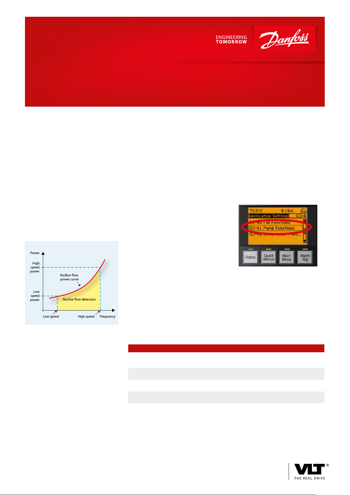
To determine the no-flow power level
throughout the speed range, the drive
generates a power vs. frequency curve
that represents the no-flow condition.
This curve is generated by the drive
from two data points. These power/
frequency points can be entered into
the drive automatically or manually.
Manual or Auto Set Up are available
The Auto Set Up automatically steps
the user through the commissioning
process, storing the data measured.
When the automatic set-up is selected
the output frequencies used are 50%
and 85% of maximum. Manual set-up
can be used when a different pair of
frequencies is desired.
Programming is quick and easy
The drive software makes programming the No Flow feature quick and
easy by choosing Pump Functions and
then No Flow Function under the Quick
Menu.
Feature Benet
Eliminates an external differential
pressure switch or flow meter
Eliminates wiring for external sensors Reduce installation and maintenance cost
A warning or alarm can alert operator
of the problem
Programming is quick and easy with
pre-programmed software
Reduce installation and maintenance cost
Provides proper operation of equipment and
increases occupant comfort
Saves time and increases reliablity
www.vlt-drives.danfoss.com
Page 2

Programming No Flow detection
Programming for No Flow detection
is simplified with a number of para-
Par.# Description
1-00 Configuration mode Open loop VLT® AQUA Drive must be set in Open Loop for Auto Set-up.
22-20 Low Power Auto Set-up Disable Enable Close the outlet valve for the pump before starting Auto Set-up.
The following parameters are accessed through the Main Menu and will be stored after pressing the [OK] key to save the results after the auto-tuning:
22-33 Low Speed
[Hz]
22-34 Low Speed Power [kW] When Low Power Auto Set-up is used, the output power
22-37 High Speed
[Hz]
22-38 High Speed Power [kW ] When Low Power Auto Set-up is used, the output power
1-00 Configuration mode Open loop Closed loop Return the VLT® AQUA Drive to Closed Loop operation if required.
Factory
setting
meters that are pre-programmed into
the drive. Prior to programming this
feature, commission the drive by using
Settings
Recommended setting
Comments
Select Enable and follow the instruction on the LCP. After Auto Set-up
is complete, open the pump outlet valve.
When Low Power Auto Set-up is used, 50% of the drive’s
maximum frequency will be stored here. This can be
manually edited, if desired.
measured under no flow conditions at 50% speed will be
stored here. This can be manually edited, if desired.
When Low Power Auto Set-up is used, 85% of the drive’s
maximum frequency will be stored here. This can be manually edited,
if desired.
measured under no flow conditions at 85% speed will be
stored here. This can be manually edited, if desired.
the parameters in the Quick Menu.
Then perform the following steps for
programming No Flow detection:
These parameters are used after Auto Set-up and the No Flow feature is operating:
22 - 30 No Flow Power When the drive is running, this parameter will show the power
22 - 31 Power Correction Factor 100% 110% This parameter is used to raise or lower the no flow power curve
The following parameters determine the action that the drive will take if a no flow condition is detected:
22-21 Low Power
Detection
22-23 No Flow Function Off Sleep Mode/Warning/Alarm Select action
22-24 No Flow Delay 10 sec. Set the time delay before the drive will perform the No Flow Function.
The following parameters give an indication to a SCADA system if a no flow condition is detected:
5-40 Function Relay [190] No Flow
Digital Output [190] No Flow
The following are used if No Flow is reported via serial communications:
Protocol Alarm Word Warning Word
Profibus/Profinet Parameter 1691 bit 5=1 Parameter 1693 bit 5=1
DeviceNet/Ethernet IP Class 116, Instance 1, Attribute 193, bit 5=1 Class 116, Instance 1, Attribute 193, bit 5=1
Modbus RTU/TCP Register 16910 Bit 5=1 Register 16930 Bit 5=1
Disable Enable To activate no flow based on power
level that will be interpreted as producing no flow at the current
motor speed.
to the percentage entered here. Values above 100% help ensure the
drive reliably detects no flow.
Generally set longer than the decel ramp time.
Program one of the relays to selection [190], No Flow.
The selected relay will be activated when No Flow occurs.
A digital output can be used to indicate a no flow condition. Use the
parameter that sets the function of the desired digital output.
Danfoss Drives, Ulsnaes 1, DK-6300 Graasten, Denmark, Tel. +45 74 88 22 22, Fax +45 74 65 25 80, www.vlt-drives.danfoss.com, E-mail: info@danfoss.com
DEDD.PFF.400.A2.02 © Copyright Danfoss Drives | 2015.10
 Loading...