

Page 1
Installation Instructions
Control Cassettes
®
VLT
Midi Drive FC 280
There are 6 types of control cassettes for VLT® Midi Drive FC
280:
Standard control cassette.
•
Control cassette with PROFIBUS.
•
Control cassette with PROFINET.
•
Control cassette with CANopen®.
•
Control cassette with EtherNet/IP™.
•
Control cassette with POWERLINK.
•
The installation instructions in this manual apply to all control
cassettes. For all control cassettes, except for the standard
cassette, mount the decoupling kit after mounting the control
cassette. Find the instructions on mounting the decoupling kit
in the kit package.
For information on how to program the control card, refer to:
VLT® Midi Drive FC 280 Programming Guide.
•
VLT® Midi Drive FC 280 PROFIBUS Programming Guide.
•
VLT® Midi Drive FC 280 PROFINET Programming Guide.
•
VLT® Midi Drive FC 280 CANopen® Programming Guide.
•
VLT® Midi Drive FC 280 EtherNet/IP™ Programming
•
Guide.
Safety Instructions
WARNING
DISCHARGE TIME
The frequency converter contains DC-link capacitors, which
can remain charged even when the frequency converter is
not powered. High voltage can be present even when the
warning LED indicator lights are
specied time after power has been removed before
performing service or repair work can result in death or
serious injury.
Stop the motor.
•
Disconnect AC mains and remote DC-link power
•
supplies, including battery back-ups, UPS, and DClink connections to other frequency converters.
Disconnect or lock PM motor.
•
Wait for the capacitors to discharge fully. The
•
minimum duration of waiting time is specied in
Tabl e 1. 1 .
Before performing any service or repair work, use
•
an appropriate voltage measuring device to make
sure that the capacitors are fully discharged.
Failure to wait the
o.
VLT® Midi Drive FC 280 POWERLINK Programming
•
Guide.
®
VLT
is a registered trademark.
®
CANopen
international users and manufacturers group e. V.
EtherNet/IP™ is a trademark of ODVA, Inc.
is a registered trademark for CAN IN AUTOMATION
Items Supplied
One of the 6 types of control cassettes:
Standard control cassette (132B0345).
•
Control cassette with PROFIBUS (132B0347).
•
Control cassette with PROFINET (132B0348).
•
Control cassette with CANopen® (132B0346).
•
Control cassette with EtherNet/IP™ (132B0349).
•
Control cassette with POWERLINK (132B0378).
•
Voltage [V] Minimum waiting time (minutes)
415
200–240 0.37–3.7 kW
(0.5–5 hp)
380–480 0.37–7.5 kW
(0.5–10 hp)
Tab le 1 .1 D isc h arg e Time
Refer to the VLT® Midi Drive FC 280 Operating Guide for detailed
information about safe installation of the frequency converter.
–
11–22 kW
(15–30 hp)
Danfoss A/S © 01/2017 All rights reserved. MI07J202
Page 2
Installation Instructions
Mounting
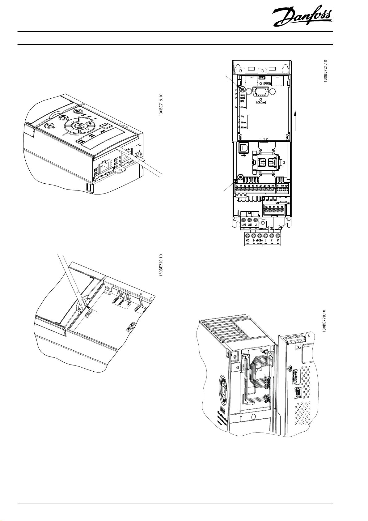
1. Remove the LCP with a at-edged screwdriver
(accessed from the top), as shown in Illustration 1.1.
Illustration 1.1 Remove LCP
Control Cassettes
®
Midi Drive FC 280
VLT
2. Remove the plastic cover beneath the LCP by
pushing down the lock lever with a at-edged
screwdriver and lift the plastic cover upwards, as
shown in Illustration 1.2.
Illustration 1.2 Remove Cover
3. Loosen the old control card cassette by removing the
2 screws (T10, M3x6) on the left side, as shown in
Illustration 1.3.
Illustration 1.3 Loosen the Old Control Card Cassette
4. Slide the old control card cassette upwards to release
it from the power section.
5. Connect the new control cassette with the frequency
converter as shown in Illustration 1.4.
Illustration 1.4 Connect the New Control Cassette
2
Danfoss A/S © 01/2017 All rights reserved. MI07J202
Page 3

Installation Instructions
Control Cassettes
®
Midi Drive FC 280
VLT
6. Place the new control cassette on the frequency
converter and slide it into place.
Illustration 1.5 Slide the New Control Cassette into Place
7. Fasten the new control cassette on the frequency
converter using 2 screws (supplied). Tightening
torque: 0.7–1.0 Nm (6.2–8.8 lb-in).
NOTICE
For the new control cassette to be properly recognized by
the frequency converter, update the software in the
frequency converter every time a new control cassette is
installed via the MCT 10 Set-up Software.
1. Select MCT 10 Set-up Software in the Start menu.
2. Select Congure bus.
3. Fill in the relevant data in the Serial eldbus congu-
ration-window.
4. Click the Scan bus-icon and
converter.
4a The frequency converter appears in the ID-
view.
5. Click Software upgrader.
6. Select the oss le.
7. In the dialog window, tick Force upgrade and then
click Start upgrade.
7a The rmware ashes.
8. Click Done when the upgrade is complete.
the frequency
nd
1Screws
Illustration 1.6 Tighten Screws
MI07J202 Danfoss A/S © 01/2017 All rights reserved.
3
Page 4

Danfoss can accept no responsibility for possible errors in catalogues, brochures and other printed material. Danfoss reserves the right to alter its products without notice. This also applies to products already on
order provided that such alterations can be made without subsequential changes being necessary in specifications already agreed. All trademarks in this material are property of the respective companies. Danfoss
and the Danfoss logotype are trademarks of Danfoss A/S. All rights reserved.
Danfoss A/S
Ulsnaes 1
DK-6300 Graasten
vlt-drives.danfoss.com
MI07J202132R0249 01/2017
*MI07J202*
 Loading...