

Danfoss VLT Micro Drive FC 51 Series Programming Manual

Programming Guide
VLT® Micro Drive FC 51

VLTp Micro Drive FC 51 Contents
Contents
1. Safety
Safety Instructions 3
Software Version and Approvals 3
General Warning 3
Avoid unintended Start 4
Before Commencing Repair Work 4
2. Introduction
Type Code 5
3. Programming
How to Programme 7
Programming with MCT-10 Set-up Software 7
Programming with the LCP 11 or LCP 12 7
Status Menu 9
Quick Menu 9
Main Menu 10
4. Parameter Descriptions
Parameter group 0: Operation/Display 11
Parameter Group 1: Load/Motor 15
Parameter Group 2: Brakes 22
Parameter Group 3: Reference/Ramps 25
Parameter Group 4: Limits/Warnings 30
Parameter Group 5: Digital In/Out 33
Parameter Group 6: Analogue In/Out 37
Parameter Group 7: Controllers 42
Parameter Group 8: Communication 44
Parameter Group 13: Smart Logic 48
Parameter Group 14: Special Functions 55
Parameter Group 15: Drive Information 57
Parameter Group 16: Data Readouts 59
16-09 Custom Readout 59
3
5
7
11
5. Parameter Lists
Conversion Index 67
Change during operation 67
2-Set-up 67
Type 67
0-** Operation/Display 68
1-** Load/Motor
MG.02.C4.02 - VLTp is a registered Danfoss trademark
63
69
1

Contents VLTp Micro Drive FC 51
2-** Brakes 70
3-** Reference/Ramps 71
4-** Limits/Warnings 72
5-** Digital In/Out 73
6-** Analog In/Out 74
7-** Controllers 75
8-** Comm. and Options 76
13-** Smart Logic 77
14-** Special Functions 78
15-** Drive Information 79
16-** Data Readouts 80
6. Troubleshooting
Alarm, Warning and Extended Status Word 82
Index
81
83
2
MG.02.C4.02 - VLTp is a registered Danfoss trademark
VLTp Micro Drive FC 51 1. Safety
1. Safety
1.1.1. High Voltage Warning
The voltage of the frequency converter is dangerous whenever it is connected to mains. Incorrect installation of the motor or frequency
converter may cause damage to the equipment, serious injury or death. Consequently, it is essential to comply with the instructions
in this manual as well as local and national rules and safety regulations.
1.1.2. Safety Instructions
• Make sure the frequency converter is properly connected to earth.
• Do not remove mains connections, motor connections or other power connections while the frequency converter is connected to power.
• Protect users against supply voltage.
• Protect the motor against overloading according to national and local regulations.
• The earth leakage current exceeds 3.5 mA.
• The [OFF] key is not a safety switch. It does not disconnect the frequency converter from mains.
1.1.3. Software Version and Approvals
Software Version
Programming Guide
VLT Micro Drive
FC 51 Series
1
This Programming Guide can be used for all VLT Micro Drive frequency drives with software version
2.1x.
The software version number can be read in
parameter 15-43.
1.1.4. General Warning
Warning:
Touching the electrical parts may be fatal - even after the equipment has been disconnected from mains.
Also make sure that other voltage inputs have been disconnected (linkage of DC intermediate circuit).
Be aware that there may be high voltage on the DC link even when the LEDs are turned off.
Before touching any potentially live parts of the frequency converter, wait at least 4 minutes for all sizes.
Shorter time is allowed only if indicated on the nameplate for the specific unit.
MG.02.C4.02 - VLTp is a registered Danfoss trademark
3
1
1. Safety VLTp Micro Drive FC 51
Leakage Current
The earth leakage current from the frequency converter exceeds 3.5 mA. According to IEC 61800-5-1 a reinforced Protective Earth
connection must be ensured by means of a min. 10mm² Cu or an addtional PE wire - with the same cable cross section as the Mains
wiring - must be terminated separately.
Residual Current Device
This product can cause a DC current in the protective conductor. Where a residual current device (RCD) is used for extra protection,
only an RCD of Type B (time delayed) shall be used on the supply side of this product. See also Danfoss Application Note on RCD, MN.
90.GX.YY.
Protective earthing of the frequency converter and the use of RCDs must always follow national and local regulations.
Motor overload protection is possible by setting Parameter 1-90 Motor thermal protection to the value ETR trip. For the North American
market: ETR functions provide class 20 motor overload protection, in accordance with NEC.
Installation in high altitudes:
For altitudes above 2 km, please contact Danfoss regarding PELV.
1.1.5. IT Mains
IT Mains
Installation on isolated mains source, i.e. IT mains.
Max. supply voltage allowed when connected to mains: 440 V.
As an option, Danfoss offers line filters for improved harmonics performance.
1.1.6. Avoid unintended Start
While the frequency converter is connected to mains, the motor can be started/stopped using digital commands, bus commands, references or via the
Local Control Panel.
• Disconnect the frequency converter from mains whenever personal safety considerations make it necessary to avoid unintended start of any
motors.
• To avoid unintended start, always activate the [OFF] key before changing parameters.
1.1.7. Disposal Instruction
Equipment containing electrical components must not be disposed of together with domestic waste.
It must be separately collected with electrical and electronic waste according to local and currently valid leg-
islation.
1.1.8. Before Commencing Repair Work
1. Disconnect FC 51 from mains (and external DC supply, if present.)
2. Wait for 4 minutes for discharge of the DC-link.
3. Disconnect DC bus terminals and brake terminals (if present)
4. Remove motor cable
4
MG.02.C4.02 - VLTp is a registered Danfoss trademark
VLTp Micro Drive FC 51 2. Introduction
2. Introduction
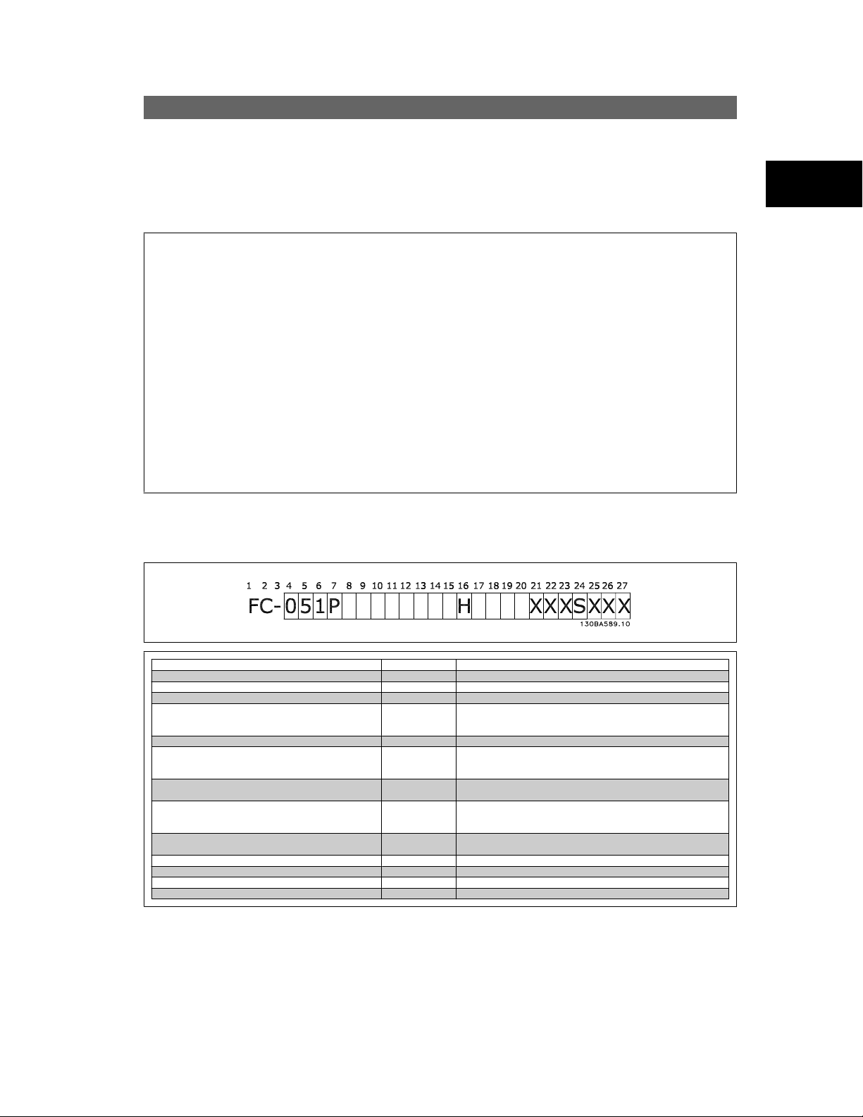
2.1.1. FC Identification
Below is an example of the frequency converter nameplate sticker. This sticker is located on the top of each frequency converter and shows the ratings,
serial number, warnings catalog number, and other relevant data for each unit. See following tables for details, how to read the Type code string.
Illustration 2.1: This example shows the identification sticker.
2.1.2. Type Code
2
Description Pos Possible choice
Product group 1-3 Adjustable Frequency Converters
Series and product type 4-6 Micro Drive
Power size 7-10 0.18 - 7.5 kW
Mains voltage 11-12 S2: Single phase 200 - 240 V AC
Enclosure 13-15 IP20/Chassis
RFI filter 16-17 HX: No RFI filter
Brake 18 B: Brake chopper included
Display 19 X: No Local Control Panel
Coating PCB 20 C: Coated PCB
Mains option 21 X: No mains option
Adaptation A 22 X: No adaptation
Adaptation B 23 X: No adaptation
Software release 24-27 SXXX: Latest release - std. software
Table 2.1: Type code description
MG.02.C4.02 - VLTp is a registered Danfoss trademark
T 2: Three phase 200 - 240 V AC
T 4: Three phase 380 - 480 V AC
H1: RFI filter class A1/B
H3:RFI filter A1/B (reduced cable length)
X: No brake chopper included
N: Numerical Local Control Panel (LCP)
P: Numerical Local Control Panel (LCP) with potentiometer
X. No coated PCB
5
2. Introduction VLTp Micro Drive FC 51
2.1.3. Symbols
Symbols used in this Programming Guide.
2
NB!
Indicates something to be noted by the reader.
Indicates a general warning.
Indicates a high-voltage warning.
* Indicates default setting
2.1.4. Abbreviations and Standards
Abbreviations: Terms: SI-units: I-P units:
AWG American wire gauge
Auto Tune Automatic Motor Tuning
rC Celsius
I
LIM
rF
FC Frequency Converter
Frequency Hz Hz
kHz Kilohertz
LCP Local Control Panel
mA Milliampere
ms Millisecond
min Minute
MCT Motion Control Tool
M-TYPE Motor Type Dependent
Nm Newton Metres in-lbs
I
M,N
f
M,N
P
M,N
U
M,N
par. Parameter
PELV Protective Extra Low Voltage
Pressure Pa = N/m² psi, psf, ft of water
I
INV
RPM Revolutions Per Minute
SR Size Related
Temperature ˚C ˚F
T
LIM
Table 2.2: Abbreviation and Standards table .
Acceleration
Current A Amp
Current limit
Energy J = N·m ft-lb, Btu
Fahrenheit
Nominal motor current
Nominal motor frequency
Nominal motor power
Nominal motor voltage
Power W Btu/hr, hp
Rated Inverter Output Current
Time s s,hr
Torque limit
Voltage V V
m/s
2
ft/s
2
6
MG.02.C4.02 - VLTp is a registered Danfoss trademark
VLTp Micro Drive FC 51 3. Programming
3. Programming
3.1. How to Programme
3.1.1. Programming with MCT-10 Set-up Software
The frequency converter can be programmed from a PC via RS485 com-port by installing the MCT-10 Set-up Software.
This software can either be ordered using code number 130B1000 or downloaded from the Danfoss Web site: www.danfoss.com, Business Area: Motion
Controls.
Please refer to manual MG.10.RX.YY.
3.1.2. Programming with the LCP 11 or LCP 12
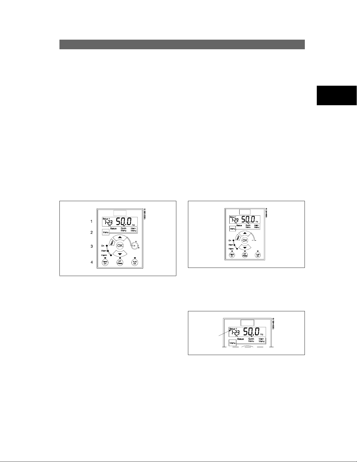
The LCP is divided into four functional groups:
1. Numeric display.
2. Menu key.
3. Navigation keys.
4. Operation keys and indicator lights (LEDs).
3
Illustration 3.1: LCP 12 with potentiometer
The display:
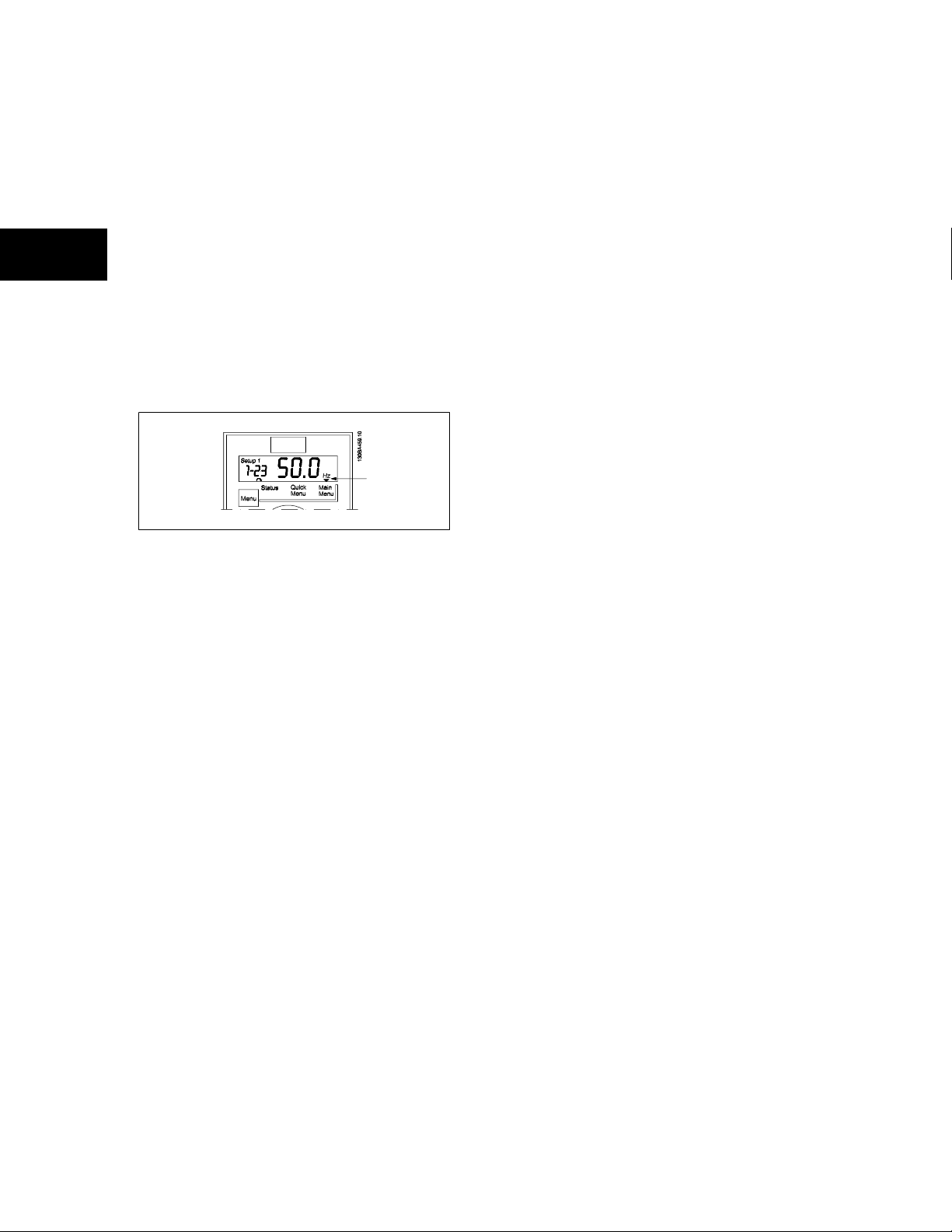
A number of information can be read from the display.
Set-up number shows the active set-up and the edit set-up. If the same
set-up acts as both active and edit set-up, only that set-up number is
shown (factory setting).
When active and edit set-up differ, both numbers are shown in the display
(Setup 12). The number flashing, indicates the edit set-up.
MG.02.C4.02 - VLTp is a registered Danfoss trademark
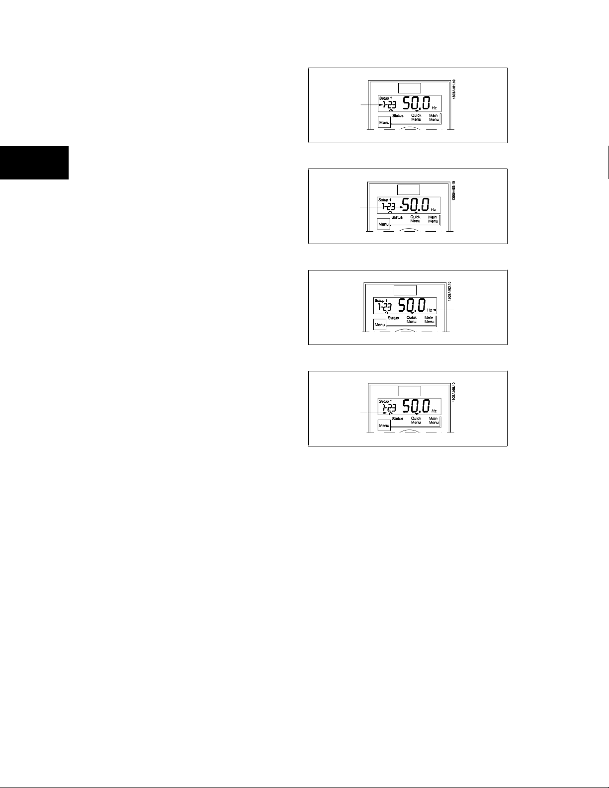
Illustration 3.2: LCP 11 without potentiometer
Illustration 3.3: Indicating Set-up
7
3
3. Programming VLTp Micro Drive FC 51
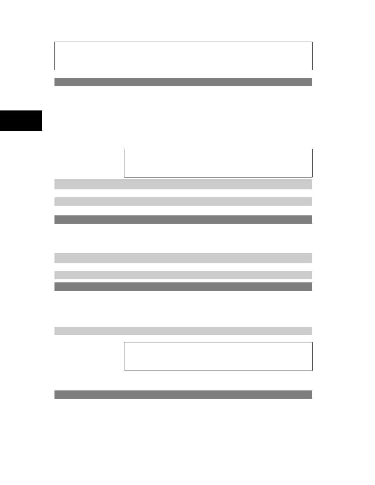
The small digits to the left are the selected parameter number.
Illustration 3.4: Indicating selected par. no.
The large digits in the middle of the display show the value of the se-
lected parameter.
Illustration 3.5: Indicating value of selected par.
The right side of the display shows the unit of the selected parameter.
This can be either Hz, A, V, kW, HP, %, s or RPM.
Illustration 3.6: Indicating unit of selected par.
Motor direction is shown to the bottom left of the display - indicated
by a small arrow pointing either clockwise or counterclockwise.
Illustration 3.7: Indicating motor direction
Use the [MENU] key to select one of the following menus:
Status Menu:
The Status Menu is either in
display.
In
Hand on Mode
Quick Menu:
Displays Quick Menu parameters and their settings. Parameters in the Quick Menu can be accessed and edited from here. Most applications can be run
by setting the parameters in the Quick Menus.
Main Menu:
Displays Main Menu parameters and their settings. All parameters can be accessed and edited here. A parameter overview is found later in this manual.
the local LCP reference is displayed.
Readout Mode
or
Hand on Mode
. In
Readout Mode
the value of the currently selected readout parameter is shown in the
Indicator lights:
• Green LED: The frequency converter is on.
• Yellow LED: Indicates a warning. Please see section
• Flashing red LED: Indicates an alarm. Please see section
8
MG.02.C4.02 - VLTp is a registered Danfoss trademark
Troubleshooting
Troubleshooting

Ⴃ
VLTp Micro Drive FC 51 3. Programming
Navigation Keys:
[Back]: For moving to the previous step or layer in the navigation structure.
Arrows [
[OK]: For selecting a parameter and for accepting changes to parameter settings.
Operation Keys:
A yellow light above the operation keys indicates the active key.
[Hand on]: Starts the motor and enables control of the frequency converter via the LCP.
[Off/Reset]: The motor stops except in alarm mode. In that case the motor will be reset.
[Auto on]: The frequency converter is controlled either via control terminals or serial communication.
[Potentiometer] (LCP12): The potentiometer works in two ways depending on the mode in which the frequency converter is running.
In
In
] [Ⴍ]: For maneuvering between parameter groups, parameters and within parameters.
Auto Mode
Hand on Mode
the potentiometer acts as an extra programmable analog input.
the potentiometer controls local reference.
3.2. Status Menu
After power up the Status Menu is active. Use the [MENU] key to toggle
between Status, Quick Menu and Main Menu.
Arrows [Ⴃ] and [Ⴍ] toggles between the choices in each menu.
The display indicates the status mode with a small arrow above “Status”.
3
Illustration 3.8: Indicating Status mode
3.3. Quick Menu
The Quick Menu gives easy access to the most frequently used parameters.
1. To enter the Quick Menu, press [MENU] key until indicator in display is placed above
2.
Use [Ⴃ] [Ⴍ] to select either QM1 or QM2, then press [OK].
3. Use [Ⴃ] [Ⴍ] to browse through the parameters in the Quick Menu.
4. Press [OK] to select a parameter.
5. Use [Ⴃ] [Ⴍ] to change the value of a parameter setting.
6. Press [OK] to accept the change.
Status
7. To exit, press either [Back] twice to enter
, or press [Menu] once to enter
Illustration 3.9: Indicating Quick Menu mode
Quick Menu
Main Menu
.
.
MG.02.C4.02 - VLTp is a registered Danfoss trademark
9
3
3. Programming VLTp Micro Drive FC 51
3.4. Main Menu
The Main Menu gives access to all parameters.
1. To enter the Main Menu, press [MENU] key until indicator in
display is placed above
2. Use [Ⴃ] [Ⴍ] to browse through the parameter groups.
3. Press [OK] to select a parameter group.
4. Use [Ⴃ] [Ⴍ] to browse through the parameters in the specific
group.
5. Press [OK] to select the parameter.
6.
Use [Ⴃ] [Ⴍ] to set/change the parameter value.
7. Press [OK] to accept the value.
8. To exit, press either [Back] twice to enter
[Menu] once to enter
Main Menu
Status
.
Quick Menu
.
, or press
Illustration 3.10: Indicating Main Menu mode
10
MG.02.C4.02 - VLTp is a registered Danfoss trademark

VLTp Micro Drive FC 51 4. Parameter Descriptions
4. Parameter Descriptions
4.1. Parameter group 0: Operation/Display
0-03 Regional Settings
Option: Function:
In order to meet the needs for different default settings in different parts of the world, par. 0-03,
Settings
, is implemented in the frequency converter. The selected setting influences the default setting of the
motor nominal frequency.
International Sets default of par. 1-23,
*
[0 ]
[1] US Sets default of par. 1-23,
Motor Frequency
Motor Frequency
NB!
This parameter cannot be adjusted while motor runs.
0-04 Operating State at Power-up (Hand Mode)
Option: Function:
This parameter controls whether or not the frequency converter should start running the motor when powering
up after a power down in Hand mode.
, to 50 Hz, shows par. 1-20 in kW.
, to 60 Hz, shows par. 1-20 in HP.
Regional
4
NB!
If LCP with potentiometer is mounted, reference is set according to actual potentiometer
value.
[0] Resume Frequency converter starts in same Hand or Off State as when powered off.
Local reference is stored and used after power-up.
Forced Stop, Ref=Old Frequency converter powers up in Off State meaning that motor is stopped after power up.
*
[1]
[2] Forced Stop, Ref=0 Frequency converter powers up in Off State meaning that motor is stopped after power up.
Local reference is stored and used after power-up.
Local reference is set to 0. Thus motor will not start running before local reference has been increased.
4.1.1. 0-1* Set-up Handling
User defined parameters and miscellaneous external inputs (eg. bus, LCP, analog/digital inputs, feedback, etc.) controls the functionality of the frequency
converter.
Set-up1
and
A complete set of all parameters controlling the frequency converter is called a set-up. The frequency converter contains 2 set-ups,
2
.
Furthermore, a fixed set of factory settings can be copied into one or more set-ups.
Some of the advantages of having more than one set-up in the frequency converter are
• Run motor in one set-up (Active Set-up) while updating parameters in another set-up (Edit Set-up)
• Connect various motors (one at a time) to frequency converter. Motor data for various motors can be placed in different set-ups.
• Rapidly change settings of frequency converter and/or motor while motor is running (eg. ramp time or preset references) via bus or digital
inputs.
Set-up
Active Set-up
The
can be set as
Multi Set-up
where the active set-up is selected via input on a digital input terminal and/or via the bus control word.
MG.02.C4.02 - VLTp is a registered Danfoss trademark
11
4
4. Parameter Descriptions VLTp Micro Drive FC 51
NB!
Factory Set-up
0-10 Active Set-up
Option: Function:
cannot be used as
Active Set-up
Active Set-up
Shifts between set-ups can only happen when
• the motor is coasted
OR
• the set-ups between which the shift happens are linked to each other (see par. 0-12,
ups
).
If changing between set-ups that are not linked, the change will not happen before motor is coasted.
.
controls the motor.
NB!
The motor is only considered stopped when it is coasted.
Linked Set-
[1 ]
[2] Set-up 2
[9] Multi Set-up Select the active set-up via digital input and/or bus, see par. 5-1* choice [23].
Set-up 1
*
Set-up 1
Set-up 2
is active.
is active.
0-11 Edit Set-up
Option: Function:
The
Edit Set-up
is for updating parameters in the frequency converter from either LCP or bus. It can be identical
or different from the
All set-ups can be edited during operation, independently of the active set-up.
[1 ]
[2] Set-up 2 Update parameters in
[9] Active Set-up Update parameters in set-up selected as
Set-up 1 Update parameters in
*
Active Set-up
Set-up 1
.
Set-up 2
.
.
Active Set-up
(see par. 0-10).
0-12 Link Set-ups
Option: Function:
The link ensures synchronizing of the “not changeable during operation” parameter values enabling shift from
one set-up to another during operation.
If the set-ups are not linked, a change between them is not possible while the motor is running. Thus the set-
up change does not occur until the motor is coasted.
[0] Not linked Leaves parameters unchanged in both set-ups and cannot be changed while motor runs.
Linked Copy parameters “not changeable during operation” parameter values into presently selected
*
[1 ]
NB!
This parameter cannot be changed while motor runs.
Edit Set-up
.
4.1.2. 0-31 Custom Readout Min Scale
0-31 Custom Readout Min Scale
Range: Function:
0.00 * [0.00 – 9999.00 ]
12
It is possible to create a customized readout related to the output frequency of the unit. The value entered in
par. 0-31 will be shown at 0 Hz. The readout can be shown in the LCP display when in Status Mode or it can be
read in par. 16-09
MG.02.C4.02 - VLTp is a registered Danfoss trademark

VLTp Micro Drive FC 51 4. Parameter Descriptions
4.1.3. 0-32 Custom Readout Max Scale
0-32 Custom Readout Max Scale
Range: Function:
100.0* [0.00 – 9999.00]
4.1.4. 0-4* LCP Keypad
It is possible to create a customized readout related to the output frequency of the unit. The value entered in
par. 0-32 will be shown at the frequency programmed in par. 4-14 Motor Speed High Limit. The readout can be
shown in the LCP display when in Status Mode or it can be read in par. 16-09
The frequency converter can operate in the following three modes:
Hand:
The frequency converter is locally operated and does not allow any remote control. By activating Hand a start signal is given.
OFF:
The frequency converter stops with a normal stop ramp. When Off is chosen the frequency converter can only be started by pressing either Hand
or Auto on the LCP.
Auto:
In Auto-mode the frequency converter can be remote controlled (bus/digital).
Hand,Off
and
Auto
.
0-40 [Hand on] Key on LCP
Option: Function:
[0] Disabled Hand-on key has no function.
[1 ]
Enabled Hand-on key is functional.
*
0-41 [Off/Reset] Key on LCP
Option: Function:
[0] Disable Off/Reset Off/reset key has no function.
[1 ]
[2] Enable Reset Only Reset only. Stop (Off) function is disabled.
Enable Off/Reset Stop signal and reset of any faults.
*
0-42 [Auto on] Key on LCP
Option: Function:
[0] Disabled Auto-on key has no function.
[1 ]
Enabled Auto-on key is functional.
*
4.1.5. 0-5* Copy/Save
0-50 LCP Copy
Option: Function:
The detachable LCP of the frequency converter can be used for storing setups, and thus for transferring data
when moving parameter settings from one frequency converter to another.
4
NB!
LCP Copy
can only be activated from the LCP and ONLY when the motor is coasted.
[1] All to LCP Copy all setups from the frequency converter into the LCP.
[2] All from LCP Copy all setups from LCP to frequency converter.
[3] Size indep. from LCP Copy non motor size dependent data from LCP to frequency converter
0-51 Set-up Copy
Option: Function:
Use this function to copy a set-up content into the
In order to be able to make a set-up copy ensure that
• the motor is coasted
• par. 0-10,
MG.02.C4.02 - VLTp is a registered Danfoss trademark
Active Set-up
, is set to either
Edit Set-up
Set-up 1
.
[1] or
Set-up 2
[2]
13
4. Parameter Descriptions VLTp Micro Drive FC 51
NB!
The keyboard/parameter database are blocked while Set-up Copy is running.
4
[0 ]
[1] Copy from Set-up 1 Copy from
[2] Copy from Set-up 2 Copy from
[9] Copy from Factory Set-upCopy from Factory Settings to edit set-up chosen in par. 0-11,
No Copy Copy function is inactive
*
Set-up 1
to edit set-up chosen in par. 0-11,
Set-up 2
to edit set-up chosen in par. 0-11,
Edit Set-up
Edit Set-up
4.1.6. 0-6* Password
0-60 (Main) Menu Password
Range: Function:
Use password for protection against unintended change of sensitive parameters, eg. motor parameters.
Password protected parameters can always be read, but cannot be edited without entering the password.
0
*
[0 - 999]
NB!
A password only has affect on the LCP - not on the bus communication.
NB!
Pressing buttons [MENU], [OK] and down will unlock the password. This will automatically enter the parameter editing screen in Quick
Menu or Main Menu.
Enter the password for access to Main Menu via the [Main Menu] key. Select the number that should allow for
changing other parameter values.
0
means there is no password.
.
.
Edit set-up
.
14
MG.02.C4.02 - VLTp is a registered Danfoss trademark

VLTp Micro Drive FC 51 4. Parameter Descriptions
4.2. Parameter Group 1: Load/Motor
1-00 Configuration Mode
Option: Function:
Use this parameter for selecting the application control principle to be used when a Remote Reference is active.
NB!
Changing this parameter will reset parameters 3-00, 3-02 and 3-03 to their default values.
NB!
This parameter cannot be adjusted while motor runs.
[0 ]
[3] Process Closed Loop Enables process closed loop control. See par. group 7-3* for further information on PI-controller.
Speed Open Loop For normal speed control (References).
*
When running in process closed loop, par. 4-10
Motor Speed Direction
must be set to
Clockwise
[0]
1-01 Motor Control Principle
Option: Function:
[0] U/f Is used for parallel connected motors and/or special motor applications. The U/f settings are set in parameters
1-55 and 1-56.
NB!
When running U/f control slip- and load compensations are not included.
[1]
VVC+ Normal running mode, including slip- and load compensations.
*
1-03 Torque Characteristics
Option: Function:
With more torque characteristics it is possible to run low energy consuming, as well as high torque applications.
[0 ]
[2] Automatic Energy Op-
Constant Torque Motor shaft output provides constant torque under variable speed control.
*
This function automatically optimizes energy consumption in centrifugal pump and fan applications. See par.
tim.
14-41
AEO Minimum Magnetisation
.
4
1-05 Hand Mode Configuration
Option: Function:
This parameter is only relevant when parameter 1-00
parameter is used for determining the reference or setpoint handling when changing from Auto Mode to Hand
Mode on the LCP.
[0] Speed Open Loop In Hand Mode the drive always runs in Open Loop configuration regardless of setting in par. 1-00
Mode
. Local potentiometer (if present) or Arrow up/down determines output frequency limited by Motor Speed
High/Low Limit (parameters 4-14 and 4-12).
[2]
*
As configuration in par.
1-00
If par. 1-00
If par. 1-00 is set to
change via local potentiometer or Arrow up/down. The change is limited by Reference Max/Min (parameters
3-02 and 3-03).
Configuration Mode
Process Closed Loop
is set to
Open Loop
Configuration Mode
[1] function is as described above.
[3] changing from Auto mode to Hand mode results in a setpoint
is set to
Process Closed Loop
4.2.1. 1-2* Motor Data
Enter the correct motor nameplate data (power, voltage, frequency, current and speed).
Run AMT, see par. 1-29.
Factory settings for advanced motor data, par. 1-3*, are automatically calculated.
MG.02.C4.02 - VLTp is a registered Danfoss trademark
[3]. The
Configuration
15

4. Parameter Descriptions VLTp Micro Drive FC 51
NB!
Parameters in parameter group 1.2* cannot be adjusted while motor runs.
4
1-20 Motor Power [kW]/[HP] (P
m.n
Option: Function:
Enter motor power from nameplate data.
Two sizes down, one size up from nominal VLT rating.
[1] 0.09 kW/0.12 HP
[2] 0.12 kW/0.16 HP
[3] 0.18kW/0.25 HP
[4] 0.25 kW/0.33 HP
[5] 0.37kW/0.50 HP
[6] 0.55 kW/0.75 HP
[7] 0.75 kW/1.00 HP
[8] 1.10 kW/1.50 HP
[9] 1.50 kW/2.00 HP
[10] 2.20 kW/3.00 HP
[11] 3.00 kW/4.00 HP
[12] 3.70 kW/5.00 HP
[13] 4.00 kW/5.40 HP
[14] 5.50 kW/7.50 HP
[15] 7.50 kW/10.0 HP
[16] 11.00 kW/15.00 HP
NB!
Changing this parameter affects par. 1-22 to 1-25,
1-30, 1-33 and 1-35.
)
1-22 Motor Voltage (U
m.n
)
Range: Function:
230/400 V [50 - 999 V] Enter motor voltage from nameplate data.
1-23 Motor Frequency (f
m.n
)
Range: Function:
50 Hz* [20-400 Hz]
1-24 Motor Current (I
Enter motor frequency from nameplate data.
)
m.n
Range: Function:
M-type dependent* [0.01 - 26.00 A]
1-25 Motor Nominal Speed (n
Enter motor current from nameplate data.
)
m.n
Range: Function:
M-type Dependent* [100 - 9999
RPM]
Enter motor nominal speed from nameplate data.
1-29 Automatic Motor Tuning (AMT)
Option: Function:
Use AMT to optimize motor performance.
16
MG.02.C4.02 - VLTp is a registered Danfoss trademark
VLTp Micro Drive FC 51 4. Parameter Descriptions
NB!
This parameter cannot be changed while motor runs.
1. Stop the frequency converter – make sure motor is at standstill
2. Choose [2] Enable AMT
3. Apply start signal
– Via LCP: Press Hand On
- Or in Remote On mode: Apply start signal on terminal 18
Off AMT function is disabled.
*
[0]
[2] Enable AMT AMT function starts running.
NB!
To gain optimum tuning of frequency converter, run AMT on a cold motor.
4.2.2. 1-3* Adv. Motor Data
Adjust advanced motor data using one of these methods:
1. Run AMT on cold motor. Frequency converter measures value from motor.
2. Enter X
3. Use R
value manually. Obtain value from motor supplier.
1
, X1, and X2default setting. Frequency converter establishes setting based on motor nameplate data.
s
4
NB!
These parameters cannot be changed while motor runs.
1-30 Stator Resistance (Rs)
Range: Function:
Depending on motor data* [Ohm]
Set stator resistance value.
1-33 Stator Leakage Reactance (X1)
Range: Function:
Depending on motor data* [Ohm]
Set stator leakage reactance of motor.
1-35 Main Reactance (X2)
Range: Function:
Depending on motor data* [Ohm]
Set motor main reactance.
MG.02.C4.02 - VLTp is a registered Danfoss trademark
17
4
4. Parameter Descriptions VLTp Micro Drive FC 51
4.2.3. 1-5* Load Independent Setting
This parameter group is for setting the load independent motor settings.
1-50 Motor Magnetization at Zero Speed
Range: Function:
This parameter enables different thermal load on motor when running at low speed.
100 %
*
[ 0 - 300%]
1-52 Min. Speed Normal Magnetizing [Hz]
Range: Function:
0.0 Hz
*
[0.0 - 10.0 Hz]
Enter a percentage of rated magnetizing current. If setting is too low, motor shaft torque may be reduced.
Use this parameter along with par. 1-50,
Set frequency required for normal magnetizing current. If frequency is set lower than motor slip frequency, par.
1-50,
Motor Magnetizing at Zero Speed
Motor Magnetizing at Zero Speed
is inactive.
.
1-55 U/f Characteristic - U
Range: Function:
This parameter is an array parameter [0-5] and is only functional when par. 1-01,
to
U/f
[0].
0.0 V
*
[0.0 - 999.9 V]
Enter voltage at each frequency point to manually form a U/f characteristic matching motor. Frequency points
are defined in par. 1-56,
1-56 U/f Characteristic - F
Range: Function:
This parameter is an array parameter [0-5] and is only functional when par. 1-01,
to
U/f
[0].
0.0 Hz
*
[0.0 - 1000.0 Hz]
Enter frequency points to manually form a U/f characteristic matching motor. Voltage at each point is defined
in par. 1-55,
Make a U/f characteristic based on 6 definable voltages and frequencies, see below figure.
Simplify U/f characteristics by merging 2 or more points (voltages and frequencies), respectively, are set equal.
U/f characteristics - F
U/f Characteristic - U
Motor Control Principle
.
Motor Control Principle
.
is set
is set
Illustration 4.1: Fig. 1 U/f characteristics
18
MG.02.C4.02 - VLTp is a registered Danfoss trademark
VLTp Micro Drive FC 51 4. Parameter Descriptions
NB!
For par. 1-56 the following applies
[0] ู [1] ู [2] ู [3] ู [4] ู [5]
4.2.4. 1-6* Load Dependent setting
Parameters for adjusting the load dependent motor settings.
1-60 Low Speed Load Compensation
Range: Function:
Use this parameter to gain optimum U/f characteristic when running at low speed.
100 %
*
[0-199 %]
Enter percentage in relation to load when motor runs at low speed.
Change-over point is automatically calculated based on motor size.
1-61 High Speed Load Compensation
Range: Function:
Use this parameter to obtain optimum load compensation when running at high speed.
100 %
*
[0 - 199 %]
Enter percentage to compensate in relation to load when motor runs at high speed.
Change-over point is automatically calculated based on motor size.
4
1-62 Slip Compensation
Range: Function:
100 %* [-400 - 399 %]
Compensation for load dependent motor slip.
Slip compensation is calculated automatically based on rated motor speed, n
NB!
This function is only active when par. 1-00,
[0], and when par. 1-01,
Motor Control Principle
Configuration Mode
, is set to
M,N
VVC+
.
, is set to
[1].
Speed Open Loop
1-63 Slip Compensation Time
Range: Function:
0.10 s [0.05 - 5.00 s] Enter slip compensation reaction speed. A high value results in slow reaction whereas a low value results in quick
reaction.
If low-frequency resonance problems arise, use longer time setting.
MG.02.C4.02 - VLTp is a registered Danfoss trademark
19

4. Parameter Descriptions VLTp Micro Drive FC 51
4.2.5. 1-7* Start Adjustments
Considering the need for various start functions in different applications, it is possible to select a number of functions in this parameter group.
1-71 Start Delay
Range: Function:
The start delay defines the time to pass from a start command is given until the motor starts accelerating.
0.0 s
*
[0.0 - 10.0 s]
Setting start delay to 0.0 sec. disables
Enter the time delay required before commencing acceleration.
Par. 1-72
Start Function
is active during
Start Function
Start delay time
, [1-72], when start command is given.
.
4
1-72 Start Function
Option: Function:
[0] DC Hold/Delay Time Motor is energized with DC holding current (par. 2-00) during start delay time.
[1] DC Brake/Delay Time Motor is energized with DC braking current (par. 2-01) during start delay time.
[2]
*
Coast/Delay Time Inverter is coasted during start delay time (inverter off).
1-73 Flying Start
Option: Function:
The Flying Start parameter is used to catch a spinning motor after eg. mains drop-out.
This function is not suitable for hoisting applications.
[0]
*
[1] Enabled Frequency converter enabled to catch spinning motor.
Disabled Flying start is not required.
NB!
When flying start is enabled par. 1-71,
function.
Start Delay
, and par. 1-72,
Start Function
4.2.6. 1-8* Stop Adjustments
To meet the need for various stop functions in different application these parameters offer some special stop features for the motor.
, have no
1-80 Function at Stop
Option: Function:
The selected function at stop is active in following situations:
• Stop command is given and output speed is ramped down to
Stop
.
• Start command is removed (standby), and output speed is ramped down to
Functions at Stop
• DC-brake command is given, and DC-brake time has passed
• While running and calculated output speed is below
[0]
*
[1] DC hold The motor is energized with a DC current. See par. 2-00
Coast The inverter is coasted.
.
1-82 Min. Speed For Function at Stop [Hz]
Range: Function:
0.0 Hz* [0.0 - 20.0 Hz]
20
Set the speed at which to activate par. 1-80
MG.02.C4.02 - VLTp is a registered Danfoss trademark
Function at Stop
Min. Speed for Activating Functions at
Min. Speed for Activating
Min. Speed for Activating Functions at Stop
DC Hold Current
.
for more information.
.

VLTp Micro Drive FC 51 4. Parameter Descriptions
4.2.7. 1-9* Motor Temperature
With an estimated motor temperature monitor the frequency converter is able to estimate motor temperature without having a thermistor mounted. It
is thus possible to receive a warning or an alarm, if motor temperature exceeds upper operational limit.
1-90 Motor Thermal Protection
Option: Function:
Using ETR (Electronic Terminal Relay) the motor temperature is calculated based on frequency, speed and time.
Danfoss recommends using The ETR function, if a thermistor is not present.
NB!
ETR calculation is based on motor data from group 1-2*.
[0]
[1] Thermistor Warning A thermistor connected to either digital or analog input gives a warning if upper limit of motor temperature
[2] Thermistor Trip A thermistor connected to either digital or analog input gives an alarm and makes the frequency converter trip
[3] ETR Warning If calculated upper limit of motor temperature range is exceeded, a warning occurs.
[4] ETR Trip If 90% of calculated upper limit of motor temperature range is exceeded, an alarm occurs and frequency con-
No Protection Disables temperature monitoring.
*
range is exceeded, (see par. 1-93,
if upper limit of motor temperature range is exceeded, (see par. 1-93,
verter trips.
NB!
When the ETR function has been selected the drive will store the recorded temperature at power down and this temperature will resume
at power up regardless of the elapsed time. Changing par. 1-90 back to [0] No Protection will reset the recorded temperature.
Thermistor Resource)
.
Thermistor Resource
.
1-93 Thermistor Resource
Option: Function:
Select the thermistor input terminal.
[0]
[1] Analog Input 53 Connect thermistor to analog input terminal 53.
None No thermistor is connected.
*
NB!
Analog input 53 cannot be selected for other purposes when selected as thermistor resource.
4
[6] Digital input 29 Connect thermistor to digital input terminal 29.
While this input functions as thermistor input, it will not respond to the function chosen in par. 5-13,
Input 29
. The value of par. 5-13 remains however unchanged in parameter database while function is inactive.
Input Digital/
Analog
Digital 10 V <800 ohm - >2.9k ohm
Analog 10 V <800 ohm - >2.9k ohm
MG.02.C4.02 - VLTp is a registered Danfoss trademark
Digital
Supply Voltage Threshold Cut-out
Values
21

4
4. Parameter Descriptions VLTp Micro Drive FC 51
4.3. Parameter Group 2: Brakes
4.3.1. 2-** Brakes
4.3.2. 2-0* DC-Brake
The purpose of DC-brake function is to brake a rotating motor by applying DC-current to the motor.
2-00 DC Hold Current
Range: Function:
This parameter either holds the motor (holding torque) or pre-heats the motor.
The parameter is active if
Stop
.
50%
*
[0 - 100%]
NB!
Avoid 100% current too long as it may overheat the motor.
Enter a value for holding current as a percentage of the rated motor current set in par. 1-24
100% DC holding current corresponds to I
2-01 DC Brake Current
Range: Function:
50 %* [0 - 150%]
Set DC-current needed to brake rotating motor.
Activate DC-brake in one of the four following ways:
1. DC-brake command, see par. 5-1* choice [5]
2. DC Cut-in function, see par. 2-04
3. DC-brake selected as start function, see par. 1-72
4. DC-brake in connection with
DC Hold
has been selected in either par. 1-72
.
M,N
Flying Start
, par. 1-73.
Start Function
or par. 1-80
Motor Current
Function at
.
2-02 DC-Braking Time
Range: Function:
DC-braking time defines the period during which
10.0 s
*
[0.0 - 60 s]
NB!
If DC-brake is activated as start function, DC-brake time is defined by
Set the time DC-braking current, set in par. 2-01, must be applied.
2-04 DC-Brake Cut-in Speed
Range: Function:
0.0 Hz* [0.0 - 400.0 Hz]
Set DC-brake cut-in speed to activate DC braking current, set in par. 2-01, when ramping down.
When set to 0 the function is off.
DC-brake current
start delay time
is applied to the motor.
.
22
MG.02.C4.02 - VLTp is a registered Danfoss trademark

VLTp Micro Drive FC 51 4. Parameter Descriptions
4.3.3. 2-1* Brake Energy Function
Use the parameters in this group for selecting dynamic braking parameters.
2-10 Brake Function
Option: Function:
Resistor Brake:
The resistor brake limits voltage in the intermediate circuit when the motor acts as generator. Without brake
resistor, the frequency converter eventually trips.
The resistor brake consumes surplus energy resulting from motor braking. A frequency converter with brake
stops a motor faster than without a brake, which is used in many applications. Requires connection of external
brake resistor.
An alternative to the resistor brake is the AC brake.
NB!
Resistor brake is only functional in frequency converters with integrated dynamic brake. An
external resistor must be connected.
AC Brake:
The AC brake consumes surplus energy by creating power loss in the motor.
It is important to keep in mind that an increase in power loss causes motor temperature to rise.
[0]
[1] Resistor Brake Resistor brake is active.
[2] AC Brake AC brake is active.
Off No brake function.
*
4
2-11 Brake Resistor (Ohm)
Range: Function:
5 * [5 - 5000 ]
Set brake resistor value.
2-16 AC Brake, Max Current
Range: Function:
100.0 %* [0.0 - 150.0 %]
Enter max. permissible current for AC-braking to avoid overheating of motor.
100% equals motor current set in par. 1-24.
2-17 Over-Voltage Control
Option: Function:
Use Over-voltage Control (OVC) to reduce the risk of the frequency converter tripping due to an over voltage
on the DC link caused by generative power from the load.
An over-voltage occurs eg. if the ramp down time is set too short compared to the actual load inertia.
[0]
[1] Enabled, not at stop OVC is running unless a stop signal is active.
[2] Enabled OVC is running, also when a stop signal is active.
Disabled The OVC is not active/required.
*
NB!
If Resistor Brake has been chosen in par. 2-10
Brake Function
the OVC is not active even though enabled in this parameter.
4.3.4. 2-2* Mechanical Brake
For hoisting applications an electro-magnetic brake is required. The brake is controlled by a relay, which releases the brake when activated.
The brake activates if frequency converter trips or a coast command is given. Furthermore, it activates when motor speed is ramped down below the
speed set in par. 2-22,
Active Brake Speed
.
MG.02.C4.02 - VLTp is a registered Danfoss trademark
23

4. Parameter Descriptions VLTp Micro Drive FC 51
2-20 Release Brake Current
Range: Function:
0.00 A* [0.00 - 100 A]
Select motor current at which mechanical brake releases.
4
2-22 Activating Mechanical Brake
Range: Function:
If the motor is stopped using ramp, the mechanical brake is activated when motor speed is less than
Brake Speed
Motor is ramped down to stop in the following situations:
• A start command is removed (stand by)
• A stop command is activated
• Quick-stop is activated (Q-stop ramp is used)
0 Hz
*
[0 - 400 Hz]
Select motor speed at which mechanical brake activates when ramping down.
Mechanical brake automatically activates if frequency converter trips or reports an alarm.
If start delay time has passed, and motor current is below
converter trips.
.
Release brake current
, frequency
Active
24
MG.02.C4.02 - VLTp is a registered Danfoss trademark
VLTp Micro Drive FC 51 4. Parameter Descriptions
4.4. Parameter Group 3: Reference/Ramps
4.4.1. 3-** Reference/Ramps
Parameters for reference handling, definition of limitations, and configuration of the frequency converter's reaction to changes
4.4.2. 3-0* Reference Limits
Parameters for setting the reference unit, limits and ranges.
3-00 Reference Range
Option: Function:
Select the range of reference and feedback signals. Values can be both positive and negative, unless par. 1-00,
Configuration Mode
[0]
[1] -Max - +Max Ranges can have both positive and negative values.
Min - Max Reference setpoint ranges can have positive values only.
*
Select this if running in Process Closed Loop.
, is set to
Process Closed Loop
[3]. In that case only positive values are allowed.
3-02 Minimum Reference
Range: Function:
0.00* [-4999 - 4999]
Enter value for minimum reference.
The sum of all internal and external references are clamped (limited) to the minimum reference value, par. 3-02.
3-03 Maximum Reference
Range: Function:
Maximum Reference is adjustable in the range Minimum Reference - 4999.
50.00
*
[-4999 - 4999]
Enter value for Maximum Reference.
The sum of all internal and external references are clamped (limited) to the maximum reference value, par.
3-03.
4.4.3. 3-1* References
Parameters for setting up the reference sources. Select the preset references for the corresponding digital inputs in parameter group 5.1*,
Inputs
.
3-10* Preset Reference
Option: Function:
Each parameter set-up contains 8 preset references which are selectable via 3 digital inputs or bus.
4
Digital
[0.00]
[18]
Bit2
0 0 0 0
001 1
0 1 0 2
011 3
1 0 0 4
101 5
1 1 0 6
111 7
Table 4.1: Par. 5-1* selection [16], [17] and [18]
-100.00 - 100.00% Enter the different preset references using array programming.
*
Normally, 100% = value set in par. 3-03,
MG.02.C4.02 - VLTp is a registered Danfoss trademark
[17]
Bit1
Maximum Reference
[16]
Bit0
Preset reference no.
.
25
 Loading...