

Danfoss VLT FC 51, VLT series, VLT Micro Drive FC 51 Quick Manual
MAKING MODERN LIVING POSSIBLE
Quick Guide
VLT® Micro Drive

Contents
1 Quick Guide
2
1.1 Safety
2
1.1.1 Warnings 2
1.1.2 Safety Instructions 2
1.2 Introduction
3
1.2.1 Available Literature 3
1.2.2 Approvals 3
1.2.3 IT Mains 3
1.2.4 Avoid Unintended Start 3
1.2.5 Disposal Instruction 3
1.3 Installation
3
1.3.1 Side-by-Side Installation 3
1.3.2 Mechanical Dimensions 4
1.3.5 Connecting to Mains and Motor 6
1.3.6 Control Terminals 6
1.3.7 Power Circuit - Overview 8
1.3.8 Load Sharing/Brake 8
1.4 Programming
9
1.4.1 Programming with LCP 9
1.7 Specifications
14
1.8 General Technical Data
16
1.9 Special Conditions
18
1.9.1 Derating for Ambient Temperature 18
1.9.2 Derating for Low Air Pressure 18
1.9.3 Derating for Running at Low Speeds 18
1.10 Options for VLT® Micro Drive
19
Index
20
Contents
VLT® Micro Drive Quick Guide
MG02B702 - VLT® is a registered Danfoss trademark 1
1 Quick Guide
1.1 Safety
1.1.1 Warnings
WARNING
HIGH VOLTAGE!
Frequency converters contain high voltage when
connected to AC mains input power. Installation, start up,
and maintenance should be performed by qualified
personnel only. Failure to perform installation, start up, and
maintenance by qualified personnel could result in death
or serious injury.
High Voltage
Frequency converts are connected to hazardous mains
voltages. Extreme care should be taken to protect against
shock. Only trained personnel familiar with electronic
equipment should install, start, or maintain this equipment.
Touching the electrical parts may be fatal - even after the
equipment has been disconnected from mains. Also make
sure that other voltage inputs have been disconnected
(linkage of DC intermediate circuit). Be aware that there
may be high voltage on the DC link even when the LEDs
are turned off. Before touching any potentially live parts of
the frequency converter, wait at least 4 min for all M1, M2
and M3 sizes. Wait at least 15 min for all M4 and M5 sizes.
WARNING
UNINTENDED START!
When the frequency converter is connected to AC mains,
the motor may start at any time. The frequency converter,
motor, and any driven equipment must be in operational
readiness. Failure to be in operational readiness when the
frequency converter is connected to AC mains could result
in death, serious injury, equipment, or property damage.
Unintended Start
When the frequency converter is connected to the AC
mains, the motor may be started by means of an external
switch, a serial bus command, an input reference signal, or
a cleared fault condition. Use appropriate cautions to
guard against an unintended start.
Leakage Current (>3.5 mA)
Follow national and local codes regarding protective
earthing of equipment with a leakage current > 3,5 mA.
frequency converter technology implies high frequency
switching at high power. This will generate a leakage
current in the earth connection. A fault current in the
frequency converter at the output power terminals might
contain a DC component which can charge the filter
capacitors and cause a transient earth current. The earth
leakage current depends on various system configurations
including RFI filtering, screened motor cables, and
frequency converter power.
EN/IEC61800-5-1 (Power Drive System Product Standard)
requires special care if the leakage current exceeds 3,5 mA.
Earth grounding must be reinforced in one of the
following ways:
•
Earth ground wire of at least 10 mm2.
•
Two separate earth ground wires both complying
with the dimensioning rules.
See EN 60364-5-54 § 543.7 for further information.
Using RCDs
Where residual current devices (RCDs), also known as earth
leakage circuit breakers (ELCBs), are used, comply with the
following:
Use RCDs of type B only which are capable of
detecting AC and DC currents.
Use RCDs with an inrush delay to prevent faults
due to transient earth currents.
Dimension RCDs according to the system configuration and environmental considerations.
Motor Thermal Protection
Motor overload protection is possible by setting Parameter
1-90 Motor thermal protection to the value ETR trip. For
the North American market: Implemented ETR function
provide class 20 motor overload protection, in accordance
with NEC.
Installation at High Altitudes
For altitudes above 2 km, contact Danfoss regarding PELV.
1.1.2
Safety Instructions
•
Make sure the frequency converter is properly
connected to earth.
•
Do not remove mains connections, motor
connections or other power connections while
the frequency converter is connected to power.
•
Protect users against supply voltage.
•
Protect the motor against overloading according
to national and local regulations.
•
The earth leakage current exceeds 3.5 mA.
•
The [Off/Reset] key is not a safety switch. It does
not disconnect the frequency converter from
mains.
Quick Guide
VLT® Micro Drive Quick Guide
2 MG02B702 - VLT® is a registered Danfoss trademark
11
1.2 Introduction
1.2.1 Available Literature
NOTE
This design guide contains the basic information necessary
for installing and running the frequency converter.
If more information is needed, the literature below can be
downloaded from:
http: //www.danfoss.com/BusinessAreas/DrivesSolutions/
Documentations
Title Literature
no.
VLT Micro Drive FC 51 Design Guide MG02K
VLT Micro Drive FC 51 Quick Guide MG02B
VLT Micro Drive FC 51 Programming Guide MG02C
FC 51 LCP Mounting Instruction MI02A
FC 51 De-coupling Plate Mounting Instruction MI02B
FC 51 Remote Mounting Kit Mounting Instruction MI02C
FC 51 DIN Rail Kit Mounting Instruction MI02D
FC 51 IP21 Kit Mounting Instruction MI02E
FC 51 Nema1 Kit Mounting Instruction MI02F
Line Filter MCC 107 Installation Instruction MI02U
Table 1.1
1.2.2
Approvals
Table 1.2
1.2.3
IT Mains
NOTE
IT Mains
Installation on isolated mains source, i.e. IT mains.
Max. supply voltage allowed when connected to mains:
440 V.
As an option, Danfoss offers recommended line filters for
improved harmonics performance.
1.2.4
Avoid Unintended Start
While the frequency converter is connected to mains, the
motor can be started/stopped using digital commands, bus
commands, references or via the LCP.
•
Disconnect the frequency converter from mains
whenever personal safety considerations make it
necessary to avoid unintended start of any
motors.
•
To avoid unintended start, always press [Off/
Reset] before changing parameters.
1.2.5
Disposal Instruction
Equipment containing electrical components
must not be disposed of together with domestic
waste.
It must be separately collected with electrical
and electronic waste according to local and
currently valid legislation.
Table 1.3
1.3
Installation
1. Disconnect FC 51 from mains (and external DC
supply, if present.)
2. Wait for 4 min (M1, M2 and M3) and 15 min (M4
and M5) for discharge of the DC-link.
3. Disconnect DC bus terminals and brake terminals
(if present).
4. Remove motor cable.
1.3.1
Side-by-Side Installation
The frequency converter can be mounted side-by-side for
IP20 rating units and requires 100 mm clearance above
and below for cooling. Refer to the specifications near the
end of this document for details on environmental ratings
of the frequency converter.
Quick Guide
VLT® Micro Drive Quick Guide
MG02B702 - VLT® is a registered Danfoss trademark 3
1 1
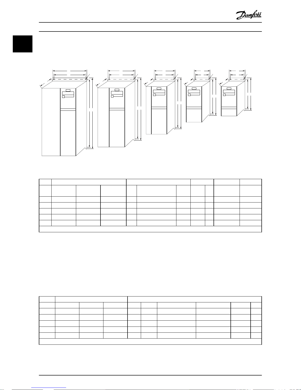
1.3.2 Mechanical Dimensions
A template for drilling can be found on the flap of the packaging.
B
a A
a A
a A
a A
a A
C
C
C C C
b
B
b
B
b
B
b
B
b
Ø 7mm
M5
M4
M3
M2
M1
Ø 7mm Ø 5.5mm Ø 4.5mm
130BB321.11
Ø 4.5mm
Illustration 1.1 Mechanical Dimensions
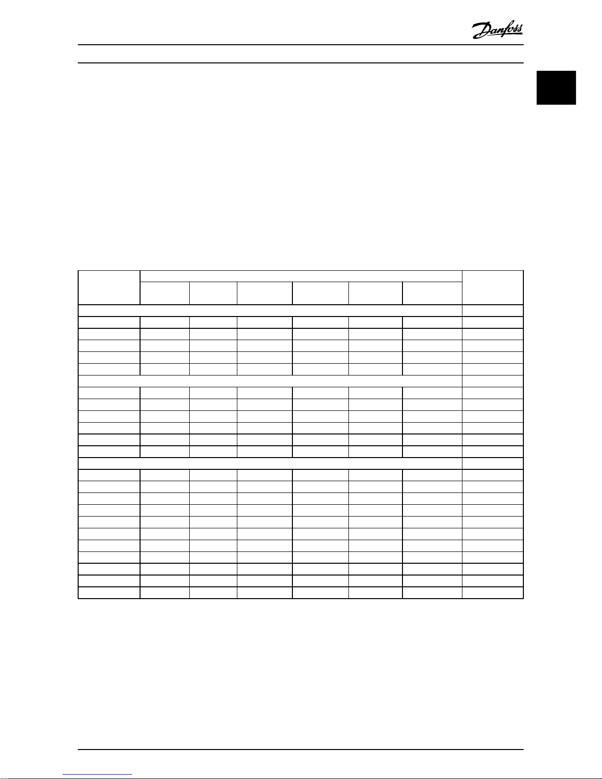
Power [kW] Height [mm] Width [mm]
Depth 1) [mm]
Max. Weight
Frame 1X200-240 V 3X200-240 V 3X380-480 V A
A (incl. decoupling
plate)
a B b C Kg
M1 0.18-0.75 0.25-0.75 0.37-0.75 150 205 140.4 70 55 148 1.1
M2 1.5 1.5 1.5-2.2 176 230 166.4 75 59 168 1.6
M3 2.2 2.2-3.7 3.0-7.5 239 294 226 90 69 194 3.0
M4 11.0-15.0 292 347.5 272.4 125 97 241 6.0
M5 18.5-22.0 335 387.5 315 165 140 248 9.5
1)
For with potentiometer, add 7.6 mm.
Table 1.4 Mechanical Dimensions
1.3.3
Electrical Installation in General
NOTE
All cabling must comply with national and local
regulations on cable cross-sections and ambient
temperature. Copper conductors required, (60-75 °C)
recommended.
Power [kW] Torque [Nm]
Frame 1x200-240 V 3x200-240 V 3x380-480 V Line Motor DC connection/Brake Control Terminals Earth Relay
M1 0.18-0.75 0.25-0.75 0.37-0.75 1.4 0.7
Spade
1)
0.15 3 0.5
M2 1.5 1.5 1.5-2.2 1.4 0.7
Spade
1)
0.15 3 0.5
M3 2.2 2.2-3.7 3.0-7.5 1.4 0.7
Spade
1)
0.15 3 0.5
M4 11.0-15.0 1.3 1.3 1.3 0.15 3 0.5
M5 18.5-22.0 1.3 1.3 1.3 0.15 3 0.5
1)
Spade connectors (6.3 mm Faston plugs)
Table 1.5 Tightening of Terminals
Quick Guide
VLT® Micro Drive Quick Guide
4 MG02B702 - VLT® is a registered Danfoss trademark
11
1.3.4 Fuses
Branch circuit protection
To protect the installation against electrical and fire hazard,
all branch circuits in an installation, switch gear, machines
etc., must be short-circuited and overcurrent protected
according to national/international regulations.
Short circuit protection
Danfoss recommends using the fuses mentioned in the
following tables to protect service personnel or other
equipment in case of an internal failure in the unit or
short-circuit on DC-link. The frequency converter provides
full short circuit protection in case of a short-circuit on the
motor or brake output.
Overcurrent protection
Provide overload protection to avoid overheating of the
cables in the installation. Overcurrent protection must
always be carried out according to national regulations.
Fuses must be designed for protection in a circuit capable
of supplying a maximum of 100,000 A
rms
(symmetrical),
480 V maximum.
Non UL compliance
If UL/cUL is not to be complied with, Danfoss recommends
using the fuses mentioned in Table 1.6, which ensures
compliance with EN50178/IEC61800-5-1:
In case of malfunction, not following the fuse recommendation may result in damage to the frequency converter
and the installation.
FC 51
Max. Fuses UL
Max. fuses non
UL
Bussmann Bussmann Bussmann Littel fuse
Ferraz-
Shawmut
Ferraz-
Shawmut
1X200-240 V
kW Type RK1 Type J Type T Type RK1 Type CC Type RK1 Type gG
0K18-0K37 KTN-R15 JKS-15 JJN-15 KLN-R15 ATM-R15 A2K-15R 16A
0K75 KTN-R25 JKS-25 JJN-25 KLN-R25 ATM-R25 A2K-25R 25A
1K5 KTN-R35 JKS-35 JJN-35 KLN-R35 - A2K-35R 35A
2K2 KTN-R50 JKS-50 JJN-50 KLN-R50 - A2K-50R 50A
3x200-240 V
0K25 KTN-R10 JKS-10 JJN-10 KLN-R10 ATM-R10 A2K-10R 10A
0K37 KTN-R15 JKS-15 JJN-15 KLN-R15 ATM-R15 A2K-15R 16A
0K75 KTN-R20 JKS-20 JJN-20 KLN-R20 ATM-R20 A2K-20R 20A
1K5 KTN-R25 JKS-25 JJN-25 KLN-R25 ATM-R25 A2K-25R 25A
2K2 KTN-R40 JKS-40 JJN-40 KLN-R40 ATM-R40 A2K-40R 40A
3K7 KTN-R40 JKS-40 JJN-40 KLN-R40 - A2K-40R 40A
3x380-480 V
0K37-0K75 KTS-R10 JKS-10 JJS-10 KLS-R10 ATM-R10 A6K-10R 10A
1K5 KTS-R15 JKS-15 JJS-15 KLS-R15 ATM-R15 A2K-15R 16A
2K2 KTS-R20 JKS-20 JJS-20 KLS-R20 ATM-R20 A6K-20R 20A
3K0 KTS-R40 JKS-40 JJS-40 KLS-R40 ATM-R40 A6K405R 40A
4K0 KTS-R40 JKS-40 JJS-40 KLS-R40 ATM-R40 A6K-40R 40A
5K5 KTS-R40 JKS-40 JJS-40 KLS-R40 - A6K-40R 40A
7K5 KTS-R40 JKS-40 JJS-40 KLS-R40 - A6K-40R 40A
11K0 KTS-R60 JKS-60 JJS-60 KLS-R60 - A6K-60R 63A
15K0 KTS-R60 JKS-60 JJS-60 KLS-R60 - A6K-60R 63A
18K5 KTS-R60 JKS-60 JJS-60 KLS-R60 - A6K-60R 80A
22K0 KTS-R60 JKS-60 JJS-60 KLS-R60 - A6K-60R 80A
Table 1.6 Fuses
Quick Guide
VLT® Micro Drive Quick Guide
MG02B702 - VLT® is a registered Danfoss trademark 5
1 1
1.3.5 Connecting to Mains and Motor
The frequency converter is designed to operate all
standard three-phased asynchronous motors.
The frequency converter is designed to accept mains/
motor cables with a maximum cross-section of 4 mm2/10
AWG (M1, M2 and M3) and maximum cross-section 16
mm2/6 AWG (M4 and M5).
•
Use a shielded/armoured motor cable to comply
with EMC emission specifications, and connect
this cable to both the decoupling plate and the
motor metal.
•
Keep motor cable as short as possible to reduce
the noise level and leakage currents.
•
For further details on mounting of the
decoupling plate, see Instruction MI02B.
•
Also see EMC-Correct Installation in Design Guide
MG02K.
1. Mount the earth wires to earth terminal.
2. Connect motor to terminals U, V and W.
3. Mount mains supply to terminals L1/L, L2 and
L3/N (3-phase) or L1/L and L3/N (single-phase)
and tighten.
Illustration 1.2 Mounting of Earth Cable, Mains and Motor Wires
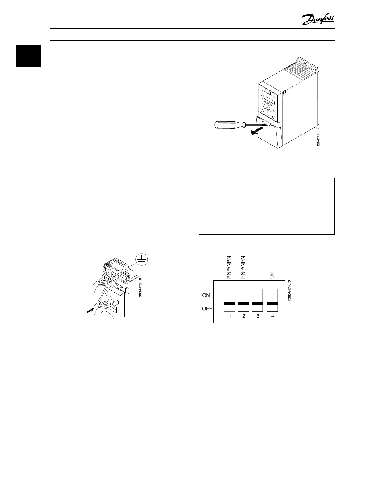
1.3.6 Control Terminals
All control cable terminals are located underneath the
terminal cover in front of the frequency converter. Remove
the terminal cover using a screwdriver.
NOTE
See back of terminal cover for outlines of control terminals
and switches.
NOTE
Do not operate switches with power on the frequency
converter.
6-19 Terminal 53 Mode must be set according to Switch 4
position.
Illustration 1.3 Removing Terminal Cover
Switch 1: *OFF=PNP terminals 29
ON=NPN terminals 29
Switch 2: *OFF=PNP terminal 18, 19, 27 and 33
ON=NPN terminal 18, 19, 27 and 33
Switch 3: No function
Switch 4: *OFF=Terminal 53 0-10 V
ON=Terminal 53 0/4-20 mA
*=default setting
Table 1.7 Settings for S200 Switches 1-4
Illustration 1.4 S200 Switches 1-4
Illustration 1.5 shows all control terminals of the frequency
converter. Applying Start (term. 18) and an analog
reference (term. 53 or 60) make the frequency converter
run.
Quick Guide
VLT® Micro Drive Quick Guide
6 MG02B702 - VLT® is a registered Danfoss trademark
11
 Loading...