

Page 1

Contents
Contents
VLT® Metasys
1 Overview
1.1.1 Software Version 2
1.1.2 Introduction 2
1.1.3 About this Manual 2
1.1.4 References 2
2 Instructions
2.1.1 Abbreviations and Definitions 3
2.1.2 Network Connection 3
2.1.3 Hardware Set-up 3
2.1.5 VLT Parameters 4
3 Appendix
3.1.1 Analog Inputs (AI) 18
3.1.2 Binary Inputs (BI) 19
3.1.3 Analog Outputs (AO) 23
3.1.4 Binary Outputs (BO) 24
3.1.5 Internal Floating Point (ADF) 25
2
3
18
3.1.6 Internal Integers (ADI) 27
Index
29
MG.11.G2.02 - VLT® is a registered Danfoss trademark 1
Page 2
Overview
VLT® Metasys
11
1 Overview
1.1.1 Software Version
VLT HVAC Drive
FC 102 Series
Software version: 3.4x
and VLT AQUA Drive FC 202 Series
Software version: 1.7x
This guide can be used with all VLT HVAC Drive frequency converters with
software version 3.4x and VLT AQUA Drive frequency converters with
software version 1.7x.
The actual software version number can be read from
par. 15-43 Software Version.
1.1.2 Introduction
The frequency converter control board is program selectable
for use with the Johnson Controls Metasys N2 protocol.
Metasys N2 is a master/slave control network. The physical
layer is RS-485 compatible, half duplex 9600 baud shielded
twisted pair. The N2 software protocol is designed to be
general in nature to accommodate the unique properties each
device type may have. Every device connection to the N2
network can be thought of as a small data manager. Data
points in the database are classified as analog I/O (floating
point), binary I/O or integer data points - floats, integers or
bytes. Each data type has its own unique structure defined in
the Metasys N2 system Protocol Specification for Vendors.
The information in this manual is intended to provide you with
comprehensive information on how to install and set up the
frequency converter for communication over a Metasys
network.
For specific information on operation of the drive, refer to the
VLT HVAC Drive Operating Instructions, MG.11.Ax.yy or the VLT
AQUA Drive Operating Instructions, MG.20.Mx.yy.
1.1.3 About this Manual
This manual is for both instructional and for reference
purposes. This manual can also serve as a guideline when you
specify and optimize your communication system.
It is highly recommended that you read this manual in its
entirety before initiating any programming. It is assumed that
the user has full knowledge of the capabilities and limitation
of the controller node in addition to full knowledge of the
frequency converter.
References
1.1.4
In addition to this manual, the following two manuals should
be consulted: VLT HVAC Drive Operating Instructions, MG.
11.Ax.yy, VLT AQUA Drive Operating Instructions, MG.20.Mx.yy
and Johnson Controls METASYS N2 System Protocol Specification
for Vendors, Johnson Controls number 04-3402-22, rev A.
2 MG.11.G2.02 - VLT® is a registered Danfoss trademark
Page 3
130BA060.11
68 69 68 69 68 69
RS 485
RS 232
USB
+
-
1 2
S801
ON
130BA272.11
Instructions
VLT® Metasys
2 Instructions
2.1.1 Abbreviations and Definitions
ACK Acknowledge
ADF Internal Floating Points
ADI Internal Integers
AI Analog Inputs
AO Analog Outputs
BI Binary Inputs
BO Binary Outputs
COS Change Of State
FC Frequency Converter
HPFB High Performance Field Bus
JCI Johnson Controls Inc. developers of the METASYS N2 protocol
N2 METASYS N2
N2
A N2 master is either a PC with JCI software or a dedicated JCI
mast
controller
er
NAK Not acknowledged
NPA N2 Point Address (Each N2 Point Type has a address range
from 0 to 255)
NPT N2 Point Type
PAR Parameter Number
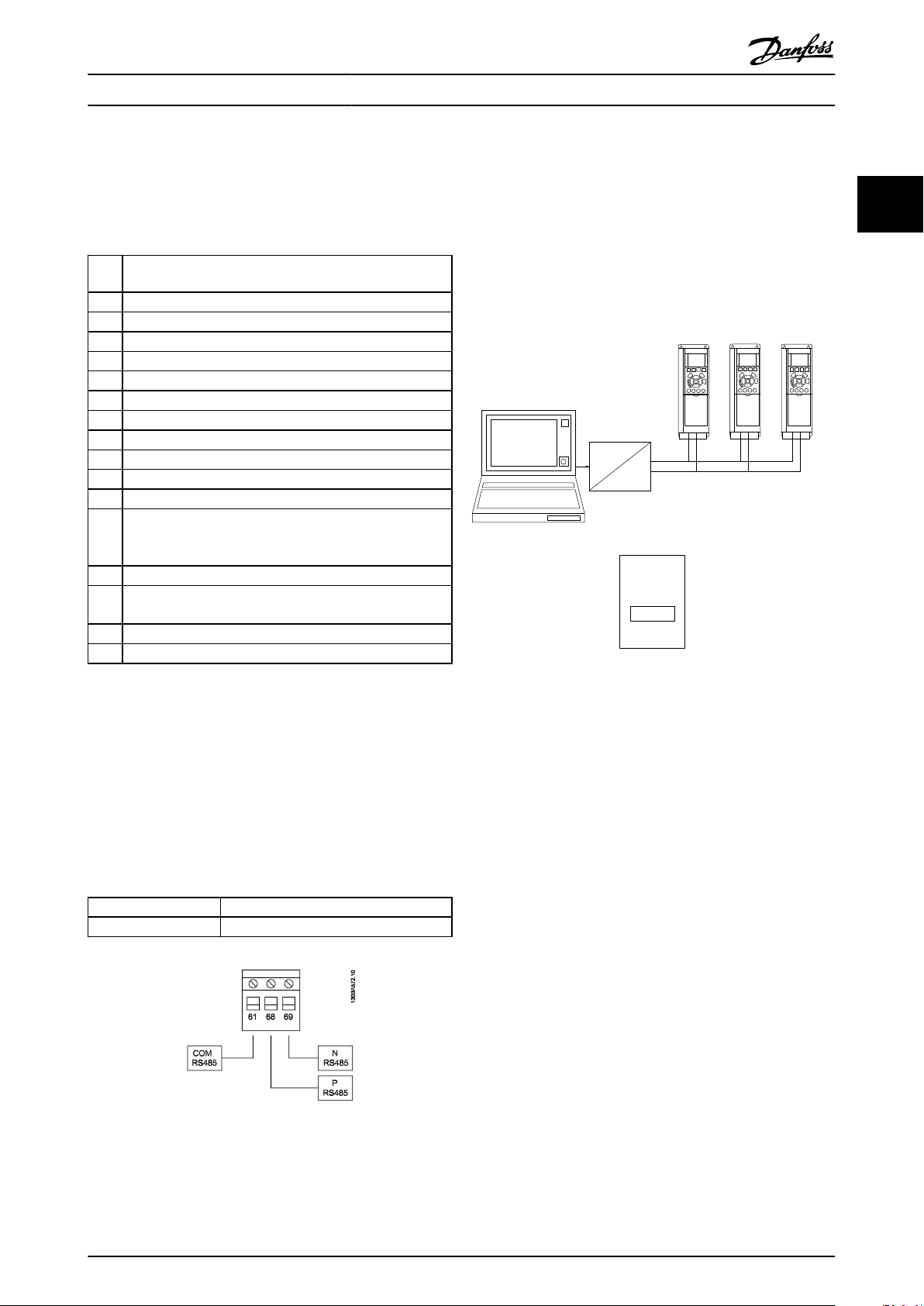
2.1.3 Hardware Set-up
RS-485 Bus Connection:
One or more frequency converters can be connected to a
control (or master) using the RS-485 standardized interface.
Terminal 68 is connected to the P signal (TX+, RX+), while
terminal 69 is connected to the N signal (TX-,RX-). If more than
one frequency converter is connected to a master, use parallel
connections.
Illustration 2.1: Bus termination switch
2 2
2.1.2 Network Connection
Connect signal wires to terminal 68 (N+) and terminal 69 (N-)
on main control board of the drive. If shielded cabling is used,
connect one end of the shield to terminal 61. This terminal is
connected to ground via an internal RC link. It is highly
recommended to use shielded twisted-pair cables to reduce
the differential mode interference between the conductors.
Danfoss do not take any responsibility for consequences, if
unshielded or untwisted cables are used.
Torque Specifications:
Control wire: 18 - 24 AWG, shielded, twisted pair
4.5 in.lb. (0.5 Nm) if screw terminal is used
NOTE
The factory setting for the dip switch is OFF.
In order to avoid potential equalizing currents in the screen,
earth the cable screen via terminal 61, which is connected to
the frame via an RC-link.
Bus termination: The RS-485 bus must be terminated by a
resistor network at both ends. For this purpose, set switch
S801 on the control card to "ON". For more information, see
the paragraph: Switches S201, S202 and S801.
MG.11.G2.02 - VLT® is a registered Danfoss trademark 3
Page 4
Instructions
2.1.4 Error Codes
VLT® Metasys
22
Error Code 00 is issued after power up or after a time out where all overridden points were released, as long as no Identify yourself
command has been issued by the master.
Error Code 01 is issued if the command is not supported or not known by the drive.
Error Code 02 is issued if the received telegram has a checksum error.
Error Code 03 is issued if the N2 telegram receive buffer exceeds 256 characters.
Error Code 05 is issued if the received N2 telegram is too long.
Error Code 10 is issued the data is out of expected range
Error Code 11 is issued when:
1. A point attributes or attribute bit is unused.
2. A point attributes or attribute bit is for JCI use only.
3. An internal data point attribute for current value can not be changed while running
Error Code 12 is issued when:
1. The N2 master tries to change attribute 2 bit 6 "Current State" on a BO and the drive is tripped.
2. The N2 master tries to change attribute 2 bit 6 "Current State" on a BO and the drive is trip locked except for BO 5
"reset"
2.1.5 VLT Parameters
The following parameters may need to be manually set for each drive in the Metasys N2 network. Refer to the VLT HVAC Drive
Design Guide, MG.11.Bx.yy, or VLT AQUA Drive Design Guide, MG.20.Nx.yy, for the frequency converter for programming.
Parameter list
VLT Parameter Description Default Desired Setting
8-01 Control Side Digital & Ctrl. Word
8-02 Control Source FC Port FC Port
8-03 Control Word Timeout 60 s 1-18000 s
8-30 Protocol FC Metasys N2
8-31 Address 1 1-255
8-32 Baud Rate 9600 Fixed to 9600
8-33 Parity Even, 1stop Fixed to No Parity, 1stop
8-37 Maximum Inter-char Delay 25 s for Metasys N2
4 MG.11.G2.02 - VLT® is a registered Danfoss trademark
Page 5
Instructions
VLT® Metasys
2.1.6 General Commands (Acknowledged)
VLT Response Command Subcommand
ACK 0 4 -
ACK 0 5 -
ACK 0 9 - Status update Message -
ACK F - - Identify Device Type -
ACK 0 0 - Synch Time -
ACK, no action 8 0 - Upload -
ACK, no action 8 1 - Upload -
ACK, no action 8 3 - Upload Record -
ACK, no action 8 4 - Upload Complete -
ACK, no action 9 0 - Download -
ACK, no action 9 1 - Download -
ACK, no action 9 3 - Download -
ACK, no action 9 4 - Download Complete -
NAK 0 1 - Read Memory 01
NPA Object
no.
Attribute Message Type Error Code Comments
Poll Message
No Acknowledge
Poll message
With Acknowledge
The slave is to respond with any data
-
-
points, analog or binary I/O that have
been flagged for COS
The slave is to respond with any data
points, analog or binary I/O that have
been flagged for COS
Slave device must respond with device
manufacturing model number (Par. 6-21),
days in service (Par. 6-00) and device
status
Slave device responds with an identifica-
tion number of 10H to indicate non JCI
device
The internal clock is syncronized by this
command
Optional, no support in the frequency
converter
Optional, no support in the frequency
converter
Optional, no support in the frequency
converter
Optional, no support in the frequency
converter
Optional, no support in the frequency
converter
Optional, no support in the frequency
converter
Record optional, no support in the
frequency converter
Optional, no support in the frequency
converter
Slave device memory read based on
memory addresses
2 2
NAK 0 8 - Warm Start 01 JCI use only
MG.11.G2.02 - VLT® is a registered Danfoss trademark 5
Page 6
Instructions
VLT® Metasys
2.1.7 Analog Input Commands (Acknowledged)
22
VLT
Response
ACK 1 - 1 0-23 1 Byte
ACK 1 - 1 0-23 2 Byte
ACK 1 - 1 0-23 3 Float
ACK 1 - 1 0-23 8 Float
ACK 1 - 1 0-23 9 Float
ACK 1 - 1 0-23 10 Float
ACK 1 - 1 0-23 11 Float
ACK 1 - 1 0-23 12 Float
ACK 2 - 1 0-23 1 Byte
ACK 2 - 1 0-23 8 Float
ACK 2 - 1 0-23 9 Float
ACK 2 - 1 0-23 10 Float
ACK 2 - 1 0-23 11 Float
ACK 2 - 1 0-23 12 Float
ACK, no
action
ACK, no
action
ACK, no
action
Command Subcom-
mand
7 2 1 0-23 - Float
7 3 1 0-23 - -
7 7 1 0-23 - -
Region
NPA Object
no.
Attribute
No.
Attribute Message Type Comments
Read Analog
Input
Read Analog
Input
Read Analog
Input
Read Analog
Input
Read Analog
Input
Read Analog
Input
Read Analog
Input
Read Analog
Input
Write Analog
Input
Write Analog
Input
Write Analog
Input
Write Analog
Input
Write Analog
Input
Write Analog
Input
Override
Analog inputs
Override
Analog Release
Write Analog
Input Attrib-
utes
Read Object Configuration attribute
associated with each individual point
1)
Read Object Status attribute
associated with each individual point
2)
Read Analog Input Value attribute
associated with each individual point
Read Low Alarm attribute associated
with each individual point
Read Low Warning attribute associ-
ated with each individual point
Read High Warning attribute associ-
ated with each individual point
Read High Alarm attribute associated
with each individual point
Read Differential attribute associated
with each individual point
Write to Object Configuration attrib-
ute associated with each individual
point
Write to Low Alarm Limit attribute
associated with each individual point
Write to Low Warning Limit attribute
associated with each individual point
Write to High Warning Limitattribute
associated with each individual point
Write to High Alarm Limit attribute
associated with each individual point
Write to Differential attribute associ-
ated with each individual point
Analog inputs are "outputs" from the
frequency converter and should not
be written over by the network
controller
Analog inputs are "outputs" from the
frequency converter and should not
be written over by the network
controller
Optional command for slave devices.
Only used for N2
commissioning purposes
6 MG.11.G2.02 - VLT® is a registered Danfoss trademark
Page 7

Instructions
VLT® Metasys
2.1.8 Analog Input Commands (Not Acknowledged)
VLT
Response
Comm and Region NPA Object no. Attribute
No.
Attribute Message Type Error
NAK 1 1 0-23 4 Float Read Analog
Input
NAK 1 1 0-23 5 Float Read Analog
Input
NAK 2 - 0-23 2 Byte Write Analog
Input
NAK 2 - 0-23 3 Float Write Analog
Input
NAK 2 - 0-23 4 Float Write Analog
Input
NAK 2 - 0-23 5 Float Write Analog
Input
NAK 2 - 0-23 6 Float Write Analog
Input
NAK 2 - 0-23 7 Float Write Analog
Input
NAK 2 - 0-23 13 Integer Write Analog
Input
NAK 2 - 0-23 14 Float Write Analog
Input
1)
Error code 11 is used because attributes are considered as fields/records in the point map database.
Comments
Code
1 )
Read Linear Ranging Parameter 1
11
attribute associated with each
individual point. (JCI use only)
1)
Read Linear Ranging Parameter 2
11
attribute associated with each
individual point. (JCI use only)
11
11
11
1)
1)
1)
Object Status writeable
Analog Input Value not writeable
Write to Linear Ranging Parame-
ter 1 attribute associated with
each individual point. (JCI use
1)
Write to Linear Ranging Parame-
11
ter 2 attribute associated with
each individual point. (JCI use
1)
Write to Linear Ranging Parame-
11
ter 3 attribute associated with
each individual point. (JCI use
1)
Write to Linear Ranging Parame-
11
ter 4 attribute associated with
each individual point. (JCI use
1)
11
Write to Filter Weight attribute
associated with each individual
point. (JCI use only)
1)
Write to AI Offset attribute associ-
11
ated with each individual point.
(JCI use only)
2 2
only)
only)
only)
only)
MG.11.G2.02 - VLT® is a registered Danfoss trademark 7
Page 8

Instructions
VLT® Metasys
2.1.9 Analog Output Commands (Acknowledged)
22
VLT
Response
ACK 1 - 3 0-2 1 Byte Read Analog
ACK 1 - 3 0-2 2 Byte Read Analog
ACK 0 9 - - - - Status update
ACK 1 - 3 0-2 3 Float Read Analog
ACK 2 - 3 0-2 1 Byte Write Analog
ACK 7 2 3 0-2 - Float Override Analog
ACK 7 2 3 0-2 - Float Override Analog
ACK 7 3 3 0-2 - - Override Release Set the current value, the value
ACK, no
action
ACK, no
action
Command Sub
command
7 7 3 0-2 - - Write Analog
7 8 3 0-2 - - Read Analog
Region NPA Object no. Attribute
No.
Attribute Message Type Comments
Output Attributes
Output
Output
Message
Output
Output
Output
Output
Output
Read Object Configuration
attribute associated with each
individual point
Read Object Status attribute
associated with each individual
point
Slave device must respond
with device manufacturing
model number (Par. 6-21), days
in service (Par. 6-00) and
device status
Read Current Value attribute
associated with each individual
point
Write to Object Configuration
attribute associated with each
individual point
Write to analog output current
value (frequency setpoint)
Write to analog output current
value (frequency setpoint)
that it was before the 1.
Override Command was issued
Optional command for slave
devices. Only used for N2
Attributes commissioning
purposes. Not to be implemen-
ted at this time
Optional command for no
action slave devices. Only used
for N2 commissioning
purposes. Not to be implemen-
ted at this time
8 MG.11.G2.02 - VLT® is a registered Danfoss trademark
Page 9

Instructions
VLT® Metasys
2.1.10 Analog Output Commands (Not Acknowledged)
VLT
Response
0-2 1 3 0-2 4 Float Read Analog
NAK 1 3 0-2 5 Float Read Analog
NAK 2 3 0-2 2 Byte Write Analog
NAK 2 3 0-2 3 Float Write Analog
NAK 2 3 0-2 4 Float Write Analog
NAK 2 3 0-2 5 Float Write Analog
Command Region NPA Object
no.
1)
Error code 11 is used because attributes are considered as fields/records in the point map database.
Attribute
No.
Attribute Message Type Error
Output
Output
Output
Output
Output
Output
Comments
Code
11
11
11
11
11
11
1
1
1
1
1
1
Read Low Linear Ranging
Parameter attribute associated
with each individual point. (JCI
use only)
Read High Linear Ranging Parameter attribute associated with
each individual point. (JCI use
Object Status not writeable
Write to Current Value structure
attributes associated with each
individual point. (N2 does not
support this, override function
must be used)
Write Debouncing Value in msec
attribute associated with each
individual point.(JCI use only)
Write Accumulator value attrib-
ute associated with each individ-
ual point. (JCI use only)
2 2
only)
MG.11.G2.02 - VLT® is a registered Danfoss trademark 9
Page 10

Instructions
VLT® Metasys
2.1.11 Binary Input (BI) Commands (Acknowledged)
22
VLT
Response
ACK 1 - 2 0-135 1 Byte Read Binary
ACK 1 - 2 0-135 2 Byte Read Binary
ACK 2 - 2 0-135 1 Byte Write Binary
ACK, no
action
ACK, no
action
ACK, no
action
ACK, no
action
Command Subcom-
mand
7 2 2 0-135 - Byte(0/1) Override Binary
7 3 2 0-135 - - OverrideRe-
7 7 2 0-135 - - Write Binary
7 8 2 0-135 - - Read Binary
Region NPA Object no. Attribute No. Attribute Message Type Comments
Input
Input
Input
Input
lease
Input
Input
Read Object Configuration
attribute associated with
each individual point
Read Object Status attribute
associated with each individ-
ual point
Write to Object Configuration
attribute associated with
each individual point
Binary inputs are "outputs"
from the frequency converter
and should not be written
over by the network control-
ler. (Status word, Warnings,
and Alarms)
Binary inputs are "outputs"
from the drive and should
not be written over by the
network controller. (Status
word, Warnings and Alarms)
Optional command for slave
devices. Only Attributes used
for N2 commissioning
purposes. Not to be
implemented at this time
Optional command for Attrib-
utes slave devices. Only used
for N2 commissioning
purposes. Not to be
implemented at this time
2.1.12 Binary Input (BI) Commands (Not Acknowledged)
VLT
Response
NAK 2 2 0-135 2 Byte Write Binary
NAK 2 2 0-135 3 Integer Write Binary
NAK 2 2 0-135 4 Integer32Write Binary
10 MG.11.G2.02 - VLT® is a registered Danfoss trademark
Command Region NPA Object
no.
Attribute No. Attribute Message Type Error
Input
Input
Input
Comments
Code
1
11
11
11
Object Status not writeable
1
Write Debouncing Value in msec
attribute associated with each
individual point.(JCI use only)
1
Write Accumulator value attrib-
ute associated with each individ-
ual point (JCI use only)
Page 11

Instructions
VLT® Metasys
2.1.13 Binary Output Commands (Acknowledged)
VLT
Response
ACK 1 - 4 0-10 1 Byte Read Binary
ACK 1 - 4 0-10 2 Byte Read Binary
ACK 2 - 4 0-10 1 Byte Write Binary
ACK 7 2 4 0-10 - Byte(0/1) Override Binary
ACK 7 2 4 0-10 - Byte(0/1) Override Binary
ACK 7 3 4 0-10 - - Override Release Set the current value, the value that
ACK, no
action
ACK, no
action
ACK, no
action
ACK, no
action
ACK, no
action
ACK, no
action
ACK, no
action
ACK, no
action
Command Subcom-
mand
1 - 4 0-10 3 Integer Read Binary
1 - 4 0-10 4 Integer Read Binary
1 - 4 0-10 5 Integer Read Binary
2 - 4 0-10 3 Integer Write Binary
2 - 4 0-10 4 Integer Write Binary
2 - 4 0-10 5 Integer Write Binary
7 7 4 0-10 - - Write Binary
7 8 4 0-10 - - Read Binary
Region NPA Object
no.
Attribute
No.
Attribute Message Type Comments
Output
Output
Output
Output
Output
Output
Output
Output
Output
Output
Output
Output
Output
Read structure attributes associated
with each individual point
Read structure attributes associated
with each individual point
Write to Object Configuration attrib-
ute associated with each
individual point
Write to binary output current state
(VLT control word)
Write to binary output current state
(VLT control word)
it was before the 1. Override
Command was issued
Read Minimum On-time attribute
associated with each
individual point. Return value = 0
Read Minimum Off-time attribute
associated with each
individual point. Return value = 0
Read Maximum Cycles/ Hour attrib-
ute associated with each
individual point. Return value = 0
Write Minimum On-time attribute
associated with each individual
point
Write Minimum Off-time attribute
associated with each individual
point
Write Maximum Cycles/ Hour attrib-
ute associated with each
individual point
Optional command for slave
devices. Only Attributes used for N2
commissioning purposes
Optional command for slave
devices. Only Attributes used for N2
commissioning purposes
2 2
MG.11.G2.02 - VLT® is a registered Danfoss trademark 11
Page 12

Instructions
VLT® Metasys
2.1.14 Binary Output (BO) Commands (Not Acknowledged)
22
VLT
Response
NAK 1 4 0-10 6 Integer Read Binary
NAK 1 4 0-10 7 Integer Read Binary
NAK 2 4 0-10 2 Byte Write Binary
NAK 2 4 0-10 6 Integer Write Binary
NAK 2 4 0-10 7 Integer Write Binary
Command Region NPA Object
no.
1)
Error code 11 is used because attributes are considered as fields/records in the point map database.
Attribute No. Attribute Message Type Error Code Comments
1)
Read Interstage on delay attrib-
11
Output
individual point. (JCI use only)
1)
Read Interstage off delay attrib-
11
Output
individual point. (JCI use only)
1)
11
Output
11
Output
11
Output
Object Status not writeable
1)
Write Interstage on delay attrib-
individual point. (JCI use only)
1)
Write Interstage off delay attrib-
individual point. (JCI use only)
ute associated with each
ute associated with each
ute associated with each
ute associated with each
2.1.15 Internal Integers (ADI) Commands (Acknowledged)
VLT
Response
ACK 1 - 6 0-254 1 Integer Read Internal
ACK 1 - 6 0-254 2 Integer Read Internal
ACK 2 - 6 0-254 - Integer Write Internal
ACK 7 2 6 0-254 - Integer Override Internal
ACK 7 3 6 0-254 - - Override Release Set the current value, the
Command Subcom-
mand
Region NPA Object no. Attribute No. Attribute Message Type Comments
Read Object Status associ-
Parameter of
object type
integer (16 bit)
Parameter of
object type
integer (16bit)
Parameter of
object type
integer (16bit)
Parameter of
object type
Integer (16 bit)
ated with each individual
point
Read Current Value attrib-
ute associated with each
individual point
Write to Current Value
attribute associated with
each individual point
Write to internal parame-
ter current value (set-up
parameters for VLT)
value that it was before
the 1. Override Command
was issued
12 MG.11.G2.02 - VLT® is a registered Danfoss trademark
Page 13

Instructions
VLT® Metasys
2.1.16 Internal Floating Point Commands (Acknowledged)
VLT
Response
ACK 1 - 5 0-101 1 Byte Read Internal
ACK 1 - 5 0-101 2 Float Read Internal
ACK 2 - 5 0-101 - Float Write Internal
ACK 2 - 5 0-101 - Float Write Internal
ACK 7 2 5 0-101 - Float Override Internal
ACK 7 3 5 0-101 - - Override Release Set the current value, the
Command Subcom-
mand
Region NPA Object no. Attribute No. Attribute Message Type Comments
Read Object Status
Parameter of
object type float
Parameter of
object type float
Parameter of
object type float
Parameter of
object type float
Parameter of
object type float
associated with each
individual point
Read Current Value
attribute associated with
each individual point
Write to Current Value
attribute associated with
each individual point
Write to Current Value
attribute associated with
each individual point
Write to internal parame-
ter current value (set-up
parameters for VLT)
value that it was before
the 1. Override
Command was issued
2 2
MG.11.G2.02 - VLT® is a registered Danfoss trademark 13
Page 14
Instructions
VLT® Metasys
2.2.1 Start-up of the Frequency Converter
22
drive or remote. Use the Extended Menu key to access the 8-**
group parameters (serial communication). The settings shown
below are typical. Some settings may be changed to meet the
application requirements. The settings below will serve as a
good starting reference. Refer to the operating instruction
manual for instructions on changing parameters and programming the drive.
Examples of typical settings. Program the following:
Parameter: Setting:
Use the frequency converter keypad mounted either on the
Par. 8-30 Protocol
Par. 8-31 Address
Par. 8-32 Baud Rate
Par. 8-50 Coasting Select
Par. 8-52 DC Brake Select
Par. 8-53 Start Select
Par. 8-54 Reversing Select
Par. 8-55 Set-up Select
Par. 8-56 Preset Reference Select
Par. 8-94 Bus Feedback 1
Par. 8-95 Bus Feedback 2
[3] Metasys N2
1 (Default)
[2] 9600 Baud (fixed at 9600 for
N2 protocol)
[3] Logic OR
[3] Logic OR
[3] Logic OR
[0] Digital input
[3] Logic OR
[3] Logic OR
0
0
Telegram code:
>XX72040401YY <CR>
Issue a frequency reference through the master, to the device:
Example 3:
Over-ride analog output, speed
(50%) change command:
Device address XX
Char1 command 7
Char1 subcommand 2
Char2 region 03
Char2 object number (NPA) 00
Char8 override value * 4E 00 00 00 override value = 50%
Checksum YY
Setting:
speed (IEEE floating point,
format)
Telegram code:
>XX7203004E000000<CR>
To calculate override value for speed: refer to Scaling of Bus
Reference and Bus Feedback. Issue an override release
command through the master to the device:
NOTE
Send an F command to begin communications between
the master and the drive
Example 1:
F command
Device address XX
Char1 command F
Checksum YY
Telegram code:
>XXFYY <CR>
Issue a run command through the master, to the device:
Example 2:
start, BO override command: Setting:
Bus
Device address XX
Char1 command 7
Char1 subcommand 2
Char2 region 04
Char2 object number (NPA) 04 (Start)
Char2 override value 01 (Active)
Checksum YY
Setting:
Example 4:
Bus stop, BO over-ride release
command:
Device address XX
Char1 command 7
Char1 subcommand 2
Char2 region 04
Char2 object number (NPA) 04 (Start)
Char8 override value * 00 (Not active)
Checksum Y
Setting:
Telegram code:
>XX72040400YY <CR>
If the preceding commands were issued, the drive should have
accelerated to 50% after the speed reference was issued. After
the override release, the drive should have stopped.
14 MG.11.G2.02 - VLT® is a registered Danfoss trademark
Page 15

Instructions
VLT® Metasys
2.2.2 Scaling of Bus Reference and Feedback
Reference/
feedback
20% 20 * 16384/100 3276.8 454C CCCD
50% 50 * 16384/100 8192 4600 0000
100%
200%
-100%
-200%
Table 2.1: Reference/feedback values
Scaling Float IEEX hex
100 *
16384/100
200 *
16384/100
-100 *
16384/100
-200 *
16384/100
16384 4680 0000
32767 46FF FE00
-16384 C680 0000
-32768 C700 0000
The reference/feedback value is the percentage of the range
of parameter 3-02 and 3-03. Values within the ranges 100% to
200% and -200% to -100% applies only to the reference. The
Float representation of the value 200% must be limited to
maximum 32767 and minimum -32768.
Status Update Request
2.2.3
A Status Update Request will cause the drive to report its
current operating status. The status codes, descriptions and
associated alarms are shown in the chart below.
The Device Status Code consists of two parts. The Least Significant Byte, (LSB) of the hex number is the Alarm Number. The
Most Significant Byte (MSB) indicates if the alarm is a normal
trip (01) that can be reset automatically or manually, or if the
alarm is a trip lock (02) requiring cycling power to the drive.
Status codes with associated alarms and descriptions
Device Status
Code1
0x0000 - Device OK
0x0102 2 Live zero error
0x0204 4 Phase fault (Trip lock)
0x0107 7 Over voltage
0x0108 8 Under voltage
0x0109 9 Inverter overloaded
0x010A 10 Motor overloaded
0x010B 11 Motor thermistor
0x010C 12 Current limit
0x020D 13 Over current (Trip lock)
0x020E 14 Earth fault (Trip lock)
0x020F 15 Switch mode fault (Trip lock)
0x0210 16 Short circuit (Trip lock)
0x0111 17 Standard bus time out
0x0112 18 HPFB time out
0x0116 22 Auto optimization not OK
0x021D 29 Heat sink temperature to high (Trip
0x011E 30 Motor phase U missing
0x011F 31 Motor phase V missing
0x0120 32 Motor phase W missing
0x0122 34 Profibus communication error
0x0225 37 Inverter fault (Trip lock)
0x013C 60 Safety interlock
0x0263 99 Unknown fault (Trip lock)
Alarm
No.
Description
lock)
Read/write notes
A write command to an ADF (Internal Floating Point) or BD
(Internal Byte) point type will be stored in the drive's EEPROM.
2 2
NOTE
If write command is issued to an overridden point, the
new value will not be stored in the drive's EEPROM.
MG.11.G2.02 - VLT® is a registered Danfoss trademark 15
Page 16
Instructions
VLT® Metasys
2.2.4 Override/Override Release Commands
Handling of Poll Message Commands
2.2.6
and Time Out, 8-04 (Setting [20], N2
Override release)
22
The way the overridden points are released is very important
to the way the drive will behave during the override release
time out or for release commands issued by the N2 master.
This is due to the fact that the active setup can be changed to
a different setup. If one would release the active setup before
the values that have been overridden in that setup, the
backup values would then be restored to the wrong setup,
leaving the overridden values in the old setup unchanged.
The release after override time out:
During an override release time-out, all points which are
overridden, will be released in the order, which they are
specified in Appendix POINTMAP:
1. Release Analog Outputs from point address (NPA) 0
to 255.
2. Release Binary Outputs from point address (NPA) 0
to 255.
3. Release Internal Floating Points from point address
(NPA) 0 to 255.
4. Release Internal Integer Points from point address
(NPA) 0 to 255.
5. Release Internal Byte points from point address
(NPA) 0 to 255.
The Identity Command will cause the drive to report all AI, AO,
BI and BO points, which are available when the next Poll (0/4)
is received. The drive also supports COS for AI and BI point
types. The drive is limited to responding with up to 200 ASCII
characters, so multiple messages may need to be sent before
all available points have been reported.
Upon receiving the Poll (0/4), the frequency converter will
begin exporting the requested information. The frequency
converter will continue to export new information upon
receiving the 0/5 Poll until it has sent all requested information. Then it will respond to a new 0/5 Poll with an ACK
response to indicate all information has been transmitted and
complete the Poll sequence receiving a 0/4 Poll before
sending the ACK response will cause the frequency converter
to re-transmit its latest response.
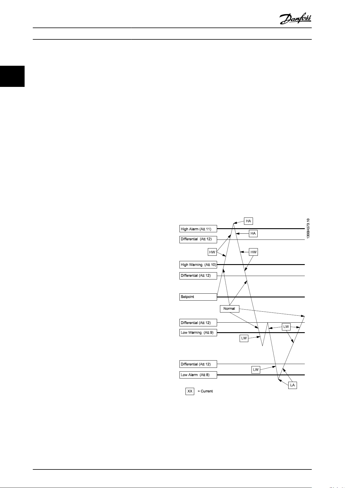
The drawing below illustrates the AI COS handling.
Change of State (COS)/POLLING
2.2.5
A change of state occurs when a new command has been
issued for the drive. This command can be issued through the
bus or through a drive related status change or command. The
master can issue a series of poll commands to the network
devices to get an update on any status changes from the time
of the last polling. When polling a frequency converter for the
first time after a network has been powered up after an F
command has been issued, a 0/4 poll command must be
issued.
16 MG.11.G2.02 - VLT® is a registered Danfoss trademark
Page 17

Instructions
For AI:
Alarm Enable or Warning Enable must be set in the Object
Configuration Attribute (Attribute 1). Low/High Alarm limits
(Attribute 8, 11) or Low/High Warning limits (Attribute 9, 10)
must be programmed. Differential Value (Attribute 12) must
also be programmed.
For BI:
Alarm Enable must be set in the Object Configuration Attribute (Attribute 1).
Normal state must be programmed in the Object Configuration Attribute (Attribute 1)
Att XX = Attribute number, HA = High alarm, LA = Low alarm,
HW = High Warning, LW = Low Warning
The AI COS alarms will only be cleared when the point value
goes below the high alarm/warning or above the low alarm/
warning limit by more than the programmed differential value
(Attribute 12).
The BI COS will set the Alarm (Object Status bit 4) if COS
enabled (Object Configuration Bit 0) is set, Alarm Enabled
(Object configuration bit 3) is set, and Current State (Object
Status bit 6) is different from Normal State (Object Configuration bit 1).
VLT® Metasys
2 2
MG.11.G2.02 - VLT® is a registered Danfoss trademark 17
Page 18

Appendix
3 Appendix
3.1.1 Analog Inputs (AI)
VLT® Metasys
3
NPA Unit Description Range FC Par. Number
0 % Reference [%] - 16-02
1 - Reference [Unit] - 16-01
2 - Feedback - 16-52
3 Hz Frequency - 16-13
4 - User defined readout - 16-09
5 A Current - 16-14
6 kW Power - 16-10
7 hp Power - 16-11
8 V Output Voltage - 16-12
9 V DC Voltage - 16-30
10 % Motor Thermal Protection - 16-18
11 % Inverter Thermal Protection - 16-35
12 V Terminal 53 analog - 16-62
13 V Terminal 54 analog - 16-64
16 % External reference - 16-50
17 C Heat sink temperature - 16-34
18 Hour Operating hours - 15-00
19 Hour Running hours - 15-01
20 kWh kWh counter - 15-02
21 - Power-ups - 15-03
22 - Over temps - 15-04
23 - Over voltages - 15-05
24 - Start Ups - 15-08
25 - Torque [%] - 16-22
26 - Speed [rpm] - 16-17
27 - Analog Input, GPIO X30/11 - 16-75
28 - Analog Input, GPIO X30/12 - 16-76
29 - Analog Input, IO option X42/1 -20.000 to +20.000 18-20
30 - Analog Input, IO optionX42/3 -20.000 to +20.000 18-21
31 - Analog Input, IO optionX42/5 -20.000 to +20.000 18-22
32 - Analog Out X42/7 - 18-33
33 - Analog Out X42/9 - 18-34
34 - Analog Out X42/11 - 18-35
40 - ECB: Bypass Running Hours
45 - Feedback 1 [Unit] - 16-54
46 - Feedback 2 [Unit] - 16-55
47 - Feedback 3 [Unit] - 16-56
48 - Ext. 1 Feedback [Unit] - 21-18
49 - Ext. 2 Feedback [Unit] - 21-38
0-232/10
31-11
The default values are shown in bold on the following pages. Any point not listed on the following pages is reserved for future
use.
Some Metasys software uses an object number range from 0 to 255, other Metasys software uses the range 1 to 254. The latter
software will interpret object number 0 as 1, and 1 as 2, etc. To access the proper point with this Metasys software, add 1 to the
NPA number in the tables.
18 MG.11.G2.02 - VLT® is a registered Danfoss trademark
Page 19

Appendix
3.1.2 Binary Inputs (BI)
NPA Unit Description Range FC Par. Number
0 15 Timers Status 0=OK, 1=Limit
1 14 Current Status 0=OK, 1=Limit
2 13 Voltage Status 0=OK, 1=Limit
3 12 Inverter Status 0=OK, 1 =Stall, Auto-start
4 11 Running Status 0=Not Running, 1=Running
5 10 Frequency Status 0=Out of Range, 1=In Range
6 9 Control Status 0=Local, 1= Bus
7 8 Reference Status 0=Not on Ref., 1=On Ref.
8 7 Warning Status 0=No Warning , 1= Warning
9 3 Tripped Status 0=No Trip , 1=Tripped
10 2 Drive Enabled Status 0=Not Enabled , 1=Enabled
11 1 Drive Ready Status 0=Not Ready, 1=Ready
12 0 Drive Controller Status 0=Not Ready, 1=Ready
16 31 Reserved
17 30 Reserved
18 29 Unused
19 28 Unused
20 27 Voltage Limit 0=OK, 1=Warning
21 26 Low Temperature 0=OK, 1=Warning
22 25 Current Limit 0=OK, 1=Warning
23 24 Mains Failure 0=OK, 1=Warning
24 23 24V Supply Low 0=OK, 1=Warning
25 22 Fieldbus Fault 0=OK, 1=Warning
26 21 Speed Limit 0=OK, 1=Warning
27 20 Brake IGBT 0=OK, 1=Warning
28 19 Brake Resistor 0=OK , 1=Warning
29 18 Brake Overload 0=OK, 1=Warning
30 17 10V low 0=OK, 1=Warning
31 16 Live Zero Error 0=OK, 1=Warning
32 15 No Motor 0=OK, 1=Warning
33 14 Mains Phase Loss 0=OK, 1=Warning
34 13 DC Voltage High 0=OK, 1=Warning
35 12 DC Voltage Low 0=OK, 1=Warning
36 11 DC Overvoltage 0=OK, 1=Warning
37 10 DC Undervoltage 0=OK, 1=Warning
38 9 Inverter Overload 0=OK, 1=Warning
39 8 Motor ETR Overload 0=OK, 1=Warning
40 7
41 6 Torque Limit 0=OK, 1=Warning
42 5 Over Current 0=OK, 1=Warning
43 4 Ctrl. Word Timeout 0=OK, 1=Warning
44 3 Ctrl. Card Temp. 0=OK, 1=Warning
45 2 Earth Fault 0=OK, 1=Warning
46 1 Pwr. Card Temp 0=OK,1=Warning
47 0 Brake Check 0=OK1=Warning
VLT® Metasys
Motor Thermal
Overload
0=OK, 1=Warning
Par. 16-03 Status Word
Par. 16-92 Warning Word
3
3
MG.11.G2.02 - VLT® is a registered Danfoss trademark 19
Page 20

3
Appendix
Binary Inputs (BI), continued..
NPA Unit Description Range FC Par. Number
48 31 Reserved
49 30 Reserved
50 29 Drive Initialized 0=OK, 1=Alarm
51 28 Option Change 0=OK, 1=Alarm
52 27 Brake IGBT 0=OK, 1=Alarm
53 26 Brake Resistor 0=OK, 1=Alarm
54 25 1.8V Supply Low 0=OK, 1=Alarm
55 24 Mains Failure 0=OK, 1=Alarm
56 23 24V Supply Low 0=OK, 1=Alarm
57 22 Fieldbus Fault 0=OK, 1=Alarm
58 21 W Phase Loss 0=OK, 1=Alarm
59 20 V Phase Loss 0=OK, 1=Alarm
60 19 U Phase Loss 0=OK, 1=Alarm
61 18 Brake Overload 0=OK, 1=Alarm
62 17 Internal Fault 0=OK, 1=Alarm
63 16 Live Zero Error 0=OK, 1=Alarm
64 15 AMA not ok 0=OK, 1=Alarm
65 14 Mains Phase Loss 0=OK, 1=Alarm
66 13 Inrush Fault 0=OK, 1=Alarm
67 12 Short Circuit 0=OK, 1=Alarm
68 11 DC Overvoltage 0=OK, 1=Alarm
69 10 DC Undervoltage 0=OK, 1=Alarm
70 9 Inverter Overload 0=OK, 1=Alarm
71 8 Motor ETR Overload 0=Trip, 1=Trip lock
72 7 Motor Thermal Overload 0=OK, 1=Alarm
73 6 Torque Limit 0=OK,1=Alarm
74 5 Over Current 0=OK,1=Alarm
75 4 Ctrl. Word Timeout 0=OK,1=Alarm
76 3 Ctrl. Card Temp 0=OK,1=Alarm
77 2 Earth Fault 0=OK,1=Alarm
78 1 Pwr. Card Temp 0=OK,1=Alarm
79 0 Brake check 0=OK,1=Alarm
80 31 0=FALSE, 1=TRUE
81 30 0=FALSE, 1=TRUE
82 29 0=FALSE, 1=TRUE
83 28 0=FALSE, 1=TRUE
84 27 0=FALSE, 1=TRUE
85 26 0=FALSE, 1=TRUE
86 25 0=FALSE, 1=TRUE
87 24 0=FALSE, 1=TRUE
88 23 0=FALSE, 1=TRUE
89 22 0=FALSE, 1=TRUE
90 21 0=FALSE, 1=TRUE
91 20 0=FALSE, 1=TRUE
92 19 0=FALSE, 1=TRUE
93 18 0=FALSE, 1=TRUE
94 17 0=FALSE, 1=TRUE
95 16 0=FALSE , 1=TRUE
96 15 OVC Active 0=FALSE , 1=TRUE
97 14 Out of Speed Reange 0=Auto mode, 1=Hand mode
VLT® Metasys
Par. 16-90 Alarm Word
Par. 16-94 Ext. Status Word
20 MG.11.G2.02 - VLT® is a registered Danfoss trademark
Page 21

Appendix
Binary Inputs (BI), continued..
NPA Unit Description Selection FC Par. Number
98 13 Braking 0=FALSE, 1=TRUE
99 12 Braking Max 0=Remote ref., 1=Local ref.
100 11 Brake Check Ok 0=FALSE, 1=TRUE
101 10 Output Frequency Low 0=FALSE, 1=TRUE
102 9 Output Frequency High 0=FALSE, 1=TRUE
103 8 Output Current Low 0=FALSE, 1=TRUE
104 7 Output Current High 0=FALSE, 1=TRUE
105 6 Feedback Low 0=FALSE, 1=TRUE
106 5 Feedback High 0=FALSE, 1=TRUE
107 4 Catch Up 0=FALSE, 1=TRUE
108 3 Slow Down 0=FALSE, 1=TRUE
109 2 Start CW/CCW 0=FALSE, 1=TRUE
110 1 AMA Running 0=FALSE, 1=TRUE
111 0 Ramping 0=FALSE, 1=TRUE
112 9 Ramp 0=RAMP 1, 1=RAMP 2
113 15 Reverse 0=No function, 1=reverse
114 14 Setup MSB 0=FALSE, 1=TRUE
115 13 Setup LSB 0=FALSE, 1=TRUE
116 12 Relay02 0=Relay04 off, 1=Relay04 on
117 11 Relay01 0=Relay01 off, 1=Relay01 on
118 10 Res., always 0 (data valid) 0=FALSE
119 8 Jog 0=No Function, 1=Jog
120 7 Reset 0=No Function, 1=Reset
121 6 Start 0=start, 1=stop
122 5 Freeze Output 0=Freeze output, 1=Ramping
123 4 Q-stop 0=Q-stop, 1=Ramping
124 3 Coast 0=Coasting, 1=no Coast
125 2 DC Brake 0=DC Brake, 1=Ramp stop
126 1 Preset ref. MSB 0=FALSE, 1=TRUE
127 0 Preset ref. LSB 0=FALSE, 1=TRUE
128 0 Terminal 33 0=FALSE, 1=TRUE
129 1 Terminal 32 0=FALSE, 1=TRUE
130 2 Terminal 29 0=FALSE, 1=TRUE
131 3 Terminal 27 0=FALSE, 1=TRUE
132 4 Terminal 19 0=FALSE, 1=TRUE
133 5 Terminal 18 0=FALSE, 1=TRUE
134 6 GPIO Term X30/2 0=FALSE, 1=TRUE
135 7 GPIO Term X30/3 0=FALSE, 1=TRUE
136 8 GPIO Terminal X30/4 0=FALSE, 1=TRUE
VLT® Metasys
Par. 16-94 Ext. Status Word
Par. 16-00 Control Word
Par. 16-60 Digital Input
3
3
MG.11.G2.02 - VLT® is a registered Danfoss trademark 21
Page 22

3
Appendix
Binary Inputs (BI), continued..
NPA Unit Description
150 10
151 9 ECB External Interlock 0=FALSE, 1=TRUE
152 8 ECB M3 Contactor Fault 0=FALSE, 1=TRUE
153 7 ECB M2 Contactor Fault 0=FALSE, 1=TRUE
154 6 ECB Overload Trip 0=FALSE, 1=TRUE
155 5
156 4 ECB Reserved 0=FALSE, 1=TRUE
157 3 ECB Bypass Mode 0=FALSE, 1=TRUE
158 2
159 1 ECB Drive Mode 0=FALSE, 1=TRUE
160 0 ECB Test Mode 0=FALSE, 1=TRUE
187 31 - 0=FALSE, 1=TRUE
188 30 - 0=FALSE, 1=TRUE
189 29 - 0=FALSE, 1=TRUE
190 28 - 0=FALSE, 1=TRUE
191 27 - 0=FALSE, 1=TRUE
192 26 - 0=FALSE, 1=TRUE
193 25 Fire Mode 0=FALSE, 1=TRUE
194 24 Drive Bypass 0=FALSE, 1=TRUE
195 23 Running 0=FALSE, 1=TRUE
196 22 Sleep Boost 0=FALSE, 1=TRUE
197 21 Sleep 0=FALSE, 1=TRUE
198 20 Start Delay 0=FALSE, 1=TRUE
199 19 Start Applied 0=FALSE, 1=TRUE
200 18 Start 0=FALSE, 1=TRUE
201 17 Start Request 0=FALSE, 1=TRUE
202 16 Jog 0=FALSE, 1=TRUE
203 15 Jog Request 0=FALSE, 1=TRUE
204 14 Freeze Output 0=FALSE, 1=TRUE
205 13 Freeze Output Request 0=FALSE, 1=TRUE
206 12 Standby 0=FALSE, 1=TRUE
207 11 Stop 0=FALSE, 1=TRUE
208 10 DC Brake 0=FALSE, 1=TRUE
209 9 Quick Stop 0=FALSE, 1=TRUE
210 8 Drive Ready 0=FALSE, 1=TRUE
211 7 Control Ready 0=FALSE, 1=TRUE
212 6 Start Prevented 0=FALSE, 1=TRUE
213 5 Relay 123 Active 0=FALSE, 1=TRUE
214 4 Profibus OFF3 Active 0=FALSE, 1=TRUE
215 3 Profibus OFF2 Active 0=FALSE, 1=TRUE
216 2 Profibus OFF1 Active 0=FALSE, 1=TRUE
217 1 Auto/Hand 0=AUTO, 1=TRUE
218 0 OFF 0=AUTO, 1=TRUE
VLT® Metasys
ECB Manual Bypass
ECB Motor Running from
Bypass/Drive
ECB Automatic Bypass
Override
Mode
Selection
0=FALSE, 1=TRUE
0=FALSE, 1=TRUE
0=FALSE, 1=TRUE
1)
FC Par. Number
Par. 31-10 Bypass Status
Word
Par. 16-95 Ext. Status Word
2
1)
The values in bold are the default values
22 MG.11.G2.02 - VLT® is a registered Danfoss trademark
Page 23

Appendix
3.1.3 Analog Outputs (AO)
NPA Unit Description Range FC Par. Number
0 %
1 Bus Feedback 1 8-94
2 Bus Feedback 2 8-95
3 Bus Feedback 3 8-96
4 Analog Output 42 6-53
5 Pulse Output 27 5-93
6 Pulse Output 29 5-95
7
8
9
10
VLT® Metasys
Bus reference
Analog Output, GPIOTer-
minal X30/8
Analog Output, IO Option
Analog Output, IO Option
Analog Output, IO Option
X42/7
X42/9
X42/11
1
-200 to 200 Proportionally
mapped into the range
-32768 to 32767
Shared Variable
6-63
26-53
26-63
26-73
3
3
MG.11.G2.02 - VLT® is a registered Danfoss trademark 23
Page 24

Appendix
3.1.4 Binary Outputs (BO)
VLT® Metasys
3
NPA Unit Description
0 2 DC Brake Inverse 0=Active, 1=Not Active
1 3 Coast Inverse 0=Active, 1=Not Active
2 4 Stop Inverse 0=Active, 1=Not Active
3 5 Freeze Output Inverse 0=Active, 1=Not Active
4 6 Start 0=Not active, 1=Active
5 7 Stop 0=Not active, 1=Active
6 8 Jog 0=Not active, 1=Active
8 11 Relay01 0=Not active, 1=Active
9 12 Relay02 0=Not active, 1=Active
10 15 Reversing 0=Not active, 1=Active
11 13 Setup LSB 0=Not active, 1=Active
12 14 Setup MSB 0=Not active, 1=Active
13 0 Preset ref. LSB 0=Not active, 1=Active
14 1 Preset ref. MSB 0=Not active, 1=Active
20 0 Output Terminal 27 0=Not active, 1=Active
21 1 Output Terminal 29 0=Not active, 1=Active
22 2 Output Terminal X30/6 0=Not active, 1=Active
23 3 Output Terminal X30/7 0=Not active, 1=Active
24 4 CC Relay 1 0=Not active, 1=Active
25 5 CC Relay 2 0=Not active, 1=Active
26 6 Option B Relay 1 0=Not active, 1=Active
27 7 Option B Relay 2 0=Not active, 1=Active
28 8 Option B Relay 3 0=Not active, 1=Active
29 9 Reserved 0=Not active, 1=Active
30 10 Reserved 0=Not active, 1=Active
31 11 Reserved 0=Not active, 1=Active
32 12 Reserved 0=Not active, 1=Active
33 13 Reserved 0=Not active, 1=Active
34 14 Reserved 0=Not active, 1=Active
35 15 Reserved 0=Not active, 1=Active
36 16 Option C Relay 1 0=Not active, 1=Active
37 17 Option C Relay 2 0=Not active, 1=Active
38 18 Option C Relay 3 0=Not active, 1=Active
39 19 Option C Relay 4 0=Not active, 1=Active
40 20 Option C Relay 5 0=Not active, 1=Active
41 21 Option C Relay 6 0=Not active, 1=Active
42 22 Option C Relay 7 0=Not active, 1=Active
43 23 Option C Relay 8 0=Not active, 1=Active
44 24 Reserved 0=Not active, 1=Active
45 25 Reserved 0=Not active, 1=Active
46 26 Reserved 0=Not active, 1=Active
47 27 Reserved 0=Not active, 1=Active
48 28 Reserved 0=Not active, 1=Active
49 29 Reserved 0=Not active, 1=Active
50 30 Reserved 0=Not active, 1=Active
52 ECB Activate 31-19
60 No Flow Detection 0=Not active, 1=Active 22-21
61
Enable Interval
between starts
0=Disable, 1=Enable 22-75
Range
1)
FC Par. Number
Par. 16-00 Control Word
Par. 5-90 Digital & Relay Bus
Control
1)
The values in BOLD are the default values.
24 MG.11.G2.02 - VLT® is a registered Danfoss trademark
Page 25

Appendix
VLT® Metasys
3.1.5 Internal Floating Point (ADF)
NPA Unit Description Range FC Par. Number
0 - Max value of custom readout 0-32
1 - Min value of custom readout 0-31
13 A
14 RPM Motor nom. Speed 1-25
16 % Resonance damping 1-64
18 Sec Start delay 1-71
19 % Preheat DC-current 2-00
20 % DC brake current 2-01
21 Sec DC braking time 2-02
22 Hz DC brake cut-in frequency 2-03
29 - Max output Frequency 4-19
34 Sec Ramp Up Time 3-41
35 Sec Ramp Down Time 3-42
36 Hz Jog Frequency 3-11
37 % Digital Reference 1 3-10:0
38 % Digital Reference 2 3-10:1
39 % Digital Reference 3 3-10:2
40 % Digital Reference 4 3-10:3
41 A Current Limit 4-18
42 Hz Frequency 1. Bypass start 4-61:0
43 Hz Frequency 1. Bypass stop 4-63:0
44 Hz Frequency 2. Bypass start 4-61:1
45 Hz Frequency 2. Bypass stop 4-63:1
46 Hz Frequency 3. Bypass start 4-61:2
47 A Frequency 3. Bypass stop 4-63:2
48 A Frequency 4. Bypass start 4-61:3
49 Hz Frequency 4. Bypass stop 4-63:3
50 A
51 A
52 Hz
53 Hz
54 Unit
55 Unit
56 Unit
57 Unit
60 V Terminal 53 min scale V 6-10
61 V Terminal 53 max scale V 6-11
62 V Terminal 53 min scale mA 6-12
63 V Terminal 53 max scale mA 6-13
64 A Terminal 54 min. scale V 6-20
65 V Terminal 54 max. scale V 6-21
66 V Terminal 54 min. scale mA 6-22
67 A Terminal 54 max. scale mA 6-23
68 Hz Terminal 42 output puls scale 5-62
69 Hz Terminal 45 output puls scale 5-65
70 mSec CC Relay 1 ON Delay 5-41:0
71 mSec CC Relay 1 ON Delay 5-42:0
72 mSec CC Relay 1 ON Delay 5-41:1
73 Sec CC Relay 1 ON Delay 5-42:1
Motor Current(I
Warning Current Low(I
Warning Current High (I
Warning Freq. Low(F
Warning Freq. High(F
Warning Low Ref.(Ref
Warning High Ref.(Ref
Warning Low FB.(FB
Warning High FB.(FB
M.N
)
LOW
HIGH
LOW
HIGH
LOW
HIGH
LOW
HIGH
)
)
)
)
)
)
)
)
1-24
4-50
4-51
4-52
4-53
4-54
4-55
4-56
4-57
3
3
MG.11.G2.02 - VLT® is a registered Danfoss trademark 25
Page 26

3
Appendix
VLT® Metasys
Internal Floating Point (ADF), continued..
NPA Unit Description Range FC Par. Number
80 Sec No Flow Timer 0-600 22-24
81 Sec Dry Pump Timer 0-600 22-27
82 Sec Minimum Run Time 0-600 22-40
83 Hz Minimum Sleep Time 0-600 22-41
84 % Boost setpoint -100% - +100% 22-45
85 Hz Wake-up Speed Par. 4-12 to 4-14 22-43
86 Sec Max Boost Time 0-600 22-46
87 kHz Switch Frequency 14-01
88 Unit Set point 1 20-21
89 Unit Set point 2 20-22
90 Hz PID Start Frequency 20-83
91 - PID Proportional Gain 20-93
92 Sec PID Integration Time 20-94
93 Sec PID Differentiation Time 20-95
94 - PID D-gain Limit 20-96
95 Unit Set Point 3 20-23
100 - Control Timeout Function 8-04
101 - Control Timeout Time 8-03
110 Sec Option B Relay 1 ON Delay 0.01 to 600.00 5-41:6
111 Sec Option B Relay 1 OFF Delay 0.01 to 600.00 5-42:6
112 Sec Option B Relay 2 ON Delay 0.01 to 600.00 5-41:7
113 Sec Option B Relay 2 OFF Delay 0.01 to 600.00 5-42:7
114 Sec Option B Relay 3 ON Delay 0.01 to 600.00 5-41:8
115 Sec Option B Relay 3 OFF Delay 0.01 to 600.00
120 V Analogue Input, GPIO option X30/11, Low Voltage 6-30
121 V Analogue Input, GPIO option X30/11, High Voltage 6-31
122 V Analogue Input, GPIO option X30/12 Low Voltage 6-40
123 V Analogue Input, GPIO option X30/12, High Voltage 6-41
124 V Analogue Input, IO X42/1, Low Voltage 0.07 to 10.00 26-10
125 V Analogue Input, IO option X42/1, High Voltage 0.07 to 10.00 26-11
126 V Analogue Input, IO option X42/3, Low Voltage 0.07 to 10.00 26-20
127 V Analogue Input, IO option, X42/3, High Voltage 0.07 to 10.00 26-21
128 V Analogue Input, IO option X42/5, Low Voltage 0.07 to 10.00 26-30
129 V Analogue Input, IO option X42/5, High Voltage 0.07 to 10.00 26-31
130 % Analogue Output 42 Timeout Preset 6-54
131 % Analogue Output, GPIO option X30/8, Timeout Preset 6-64
132 % Analogue Output, IO option X42/7, Timeout Preset 0.00 to 100.00 26-54
133 % Analogue Output, IO option X42/9, Timeout Preset 0.00 to 100.00 26-64
134 % Analogue Output, IO option X42/11, Timeout Preset 0.00 to 100.00 26-74
140 Ext. 1 Setpoint 21-15
141 Ext. 1 Proportinal Gain 21-21
142 Ext. 1 Integral Gain 21-22
143 Ext. 1 Differentation Time 21-23
144 Ext. 2 Setpoint 21-35
145 Ext. 2 Proportinal Gain 21-41
146 Ext. 2 Integral Time 21-42
147 Ext. 2 Differentation Time 21-43
26 MG.11.G2.02 - VLT® is a registered Danfoss trademark
Page 27

Appendix
VLT® Metasys
3.1.6 Internal Integers (ADI)
NPA Unit Description Range FC Par. Number
0 - Language Selection 0-01
1 - Setup Copy Function 0-51
2 - Custom Readout Unit 0-30
3 - Large Readout 0-23
4 - Small Readout 1 0-20
5 - Small Readout 2 0-21
6 - Small Readout 3 0-22
7 - Unit of Local Reference 0-05
8 - Hand Start Button 0-40
9 - Off/Stop Button 0-41
10 - Auto Start Button 0-42
11 - Reset Button 0-43
13 - Operating State at Power Up 0-04
21 - Torque Characteristics 1-03
23 - Motor Preheat 2-00
24 - Motor Thermal Protection 1-90
31 - Reference Site 3-13
32 - Over Volt Control 2-17
33 - Reference Function 3-04
40 - Digital Input 18 5-10
41 - Digital Input 19 5-11
42 - Digital Input 27 5-12
43 - Digital Input 29 5-13
44 - Digital Input 32 5-14
45 - Digital Input 33 5-15
51 Sec Live Zero Time Out 6-00
52 - Live Zero Function 6-01
53 - Signal Output 42 6-50
55 - CC Relay 1 Function 0 to 255 5-40:0
56 - CC Relay 2 Function 0 to 255 5-40:1
57 - Option B Relay 1 Function 0 to 255 5-40:6
58 - Option B Relay 2 Function 0 to 255 5-40:7
59 - Option B Relay 3 Function 0 to 255 5-40:8
60 - Reset Function 14-20
61 - Flying Start 1-73
62 - Noise Reduction Method 14-04
63 - Broken Belt Function 22-60
3
3
MG.11.G2.02 - VLT® is a registered Danfoss trademark 27
Page 28

3
Appendix
VLT® Metasys
Internal Integers (ADI), continued..
NPA Unit Description Range FC Par. Number
64 Sec Trip Delay on Overload 14-25
68 - PID Normal/Inverse 20-81
69 - PID Anti Windup 20-91
70 - Feedback 1 Conversion 20-01
71 - Feedback 1 Source Unit 20-02
72 - Feedback 2 Conversion 20-04
73 - Feedback 2 Source Unit 20-05
75 - Two Feedback Calculation 20-20
80 - Coasting 8-50
81 - DC Brake 8-52
82 - Start 8-53
83 - Reversing 8-54
84 - Selection of Setup 8-55
85 - Selection of Speed 8-56
90 - Reset kWh Counter 15-06
91 - Reset Running Hours Counter 15-07
92 - Operation Mode 14-22
101 -
102 -
103 -
104 -
105 -
106 -
107 -
110 - ECB Bypass Mode 0 - 4 31-00
111 - ECB Bypass Start Timer Delay 0 - 60 31-01
112 - ECB Bypass Trip Bypass Delay 0 - 300 31-02
120 - Dry Pump Function 0 - 2 22-26
121 - Broken Belt Action 0 - 2 22-60
122 % Broken Belt Torque 0 - 100% 22-61
123 sec Broken Belt Timer 0 - 600 22-62
124 sec Interval Between Starts Par. 22-76 - 36-00 22-76
125 sec Minimum Run Time Par. 22-77 - 36-00 22-77
254 - Active Setup 0-10
Analogue Input, IO option X42/1
Mode
Analogue Input, IO option X42/3
Mode
Analogue Input, IO option X42/5
Mode
Analogue Input, GPIO option X30/8
Mode
Analogue Input, IO option X42/7
mode
Analogue Input, IO option X42/9
Mode
Analogue Input, IO option X42/11
Mode
0 - 3 26-00
0 - 3 26-01
0 - 3 26-02
0 -145 26-50
0 -145 26-60
0 -145 26-70
6-60
28 MG.11.G2.02 - VLT® is a registered Danfoss trademark
Page 29

Index
VLT® Metasys
Index
A
Abbreviations And Definitions 3
Analog Input Commands (acknowledged) 6
Analog Input Commands (not Acknowledged) 7
Analog Inputs (ai) 18
Analog Output Commands (acknowledged) 8
Analog Output Commands (not Acknowledged) 9
Analog Outputs (ao) 23
B
Binary Input (bi) Commands (acknowledged) 10
Binary Input (bi) Commands (not Acknowledged) 10
Binary Inputs (bi) 19
Binary Output (bo) Commands (not Acknowledged) 12
Binary Output Commands (acknowledged) 11
Binary Outputs (bo) 24
C
Change Of State (cos)/polling
V
VLT Parameters 4
16
E
Error Codes
G
General Commands (acknowledged)
H
Handling Of Poll Message Commands
Hardware Set-up 3
I
Internal Floating Point (adf)
Internal Floating Point Commands (acknowledged) 13
Internal Integers (adi) 27
Internal Integers (adi) Commands (acknowledged) 12
N
Network Connection
O
Override/override Release Commands And Time Out
R
Reference/feedback Values
References 2
4
5
16
25
3
16
15
S
Scaling Of Bus Reference And Feedback
Software Version 2
Start-up Of The Frequency Converter 14
Status Update Request 15
T
Typical Settings
MG.11.G2.02 - VLT® is a registered Danfoss trademark 29
15
14
 Loading...