

Page 1
Operating Guide
VLT® Soft Starter MCD 600
Page 2

Page 3

Operating Guide | VLT® Soft Starter MCD 600
Contents
Contents
1 Introduction 8
1.1 Product Description 8
1.2 Document Version 8
1.3 Additional Resources 8
1.4 Approvals and Certifications 8
2 Safety 9
2.1 Safety Symbols 9
2.2 Qualified Personnel 9
2.3 Safety Precautions 9
3 System Design 12
3.1 Feature List 12
3.2 Type Code 13
3.3 Selection of Soft Starter Size 14
3.4 Current Ratings (IEC Ratings) 14
3.5 Dimensions and Weight 16
3.6 Physical Installation/Cooling Clearances 17
3.7 Accessories 17
3.7.1 Expansion Cards 17
3.7.1.1 Smart Card 17
3.7.1.2 Communication Expansion Cards 18
3.7.2 Remote LCP 601 18
3.7.3 Finger Guard Kit 18
3.7.4 Soft Starter Management Software 18
3.8 Main Contactor 18
3.9 Circuit Breaker 19
3.10 Power Factor Correction 19
3.11 Short-circuit Protection Devices 20
3.11.1 Type 1 Coordination 20
3.11.2 Type 2 Coordination 20
3.12 IEC Coordination with Short-circuit Protection Devices 20
3.13 UL Coordination with Short-circuit Protection Devices 21
3.13.1 Standard Fault Short-circuit Current Ratings 21
3.13.2 High Fault Short-circuit Current Ratings 22
3.14 Fuse Selection for Type 2 Coordination 23
4 Specifications 25
4.1 Supply 25
4.2 Short-circuit Capability 25
AQ262141844215en-000202 / 175R1174 | 3Danfoss A/S © 2018.10
Page 4

Operating Guide | VLT® Soft Starter MCD 600
4.3 Electromagnetic Capability (Compliant with EU Directive 2014/35/EU) 25
4.4 Inputs 25
4.5 Outputs 25
4.6 Environmental 26
4.7 Heat Dissipation 26
4.8 Motor Overload Protection 26
4.9 Certification 26
4.10 Operational Life (Internal Bypass Contacts) 26
Contents
5 Installation 27
5.1 Safety Instructions 27
5.2 Command Source 27
5.3 Setting up the Soft Starter 28
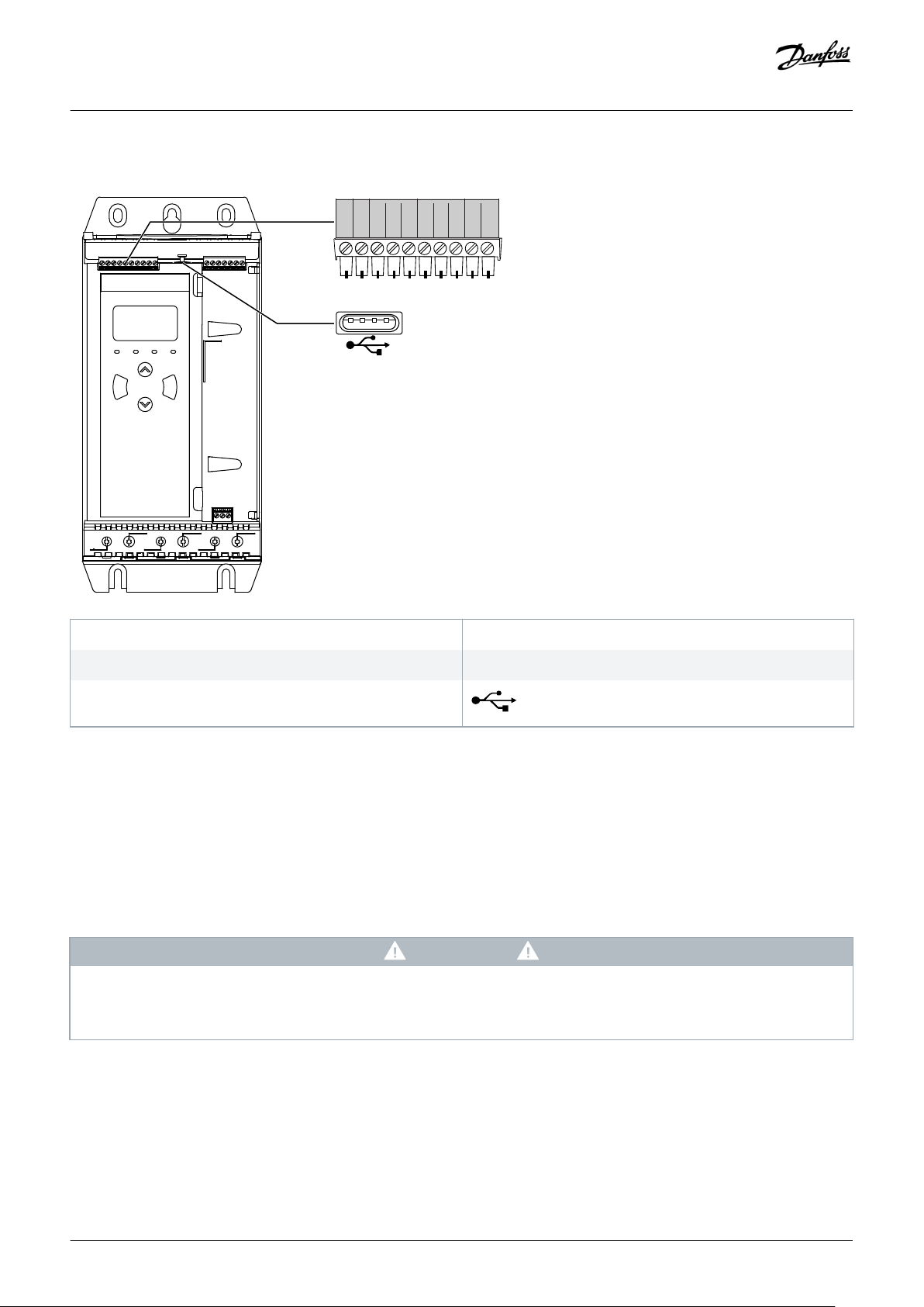
5.4 Inputs 28
5.4.1 Input Terminals 29
5.4.2 Motor Thermistor 29
5.4.3 Start/Stop 29
5.4.4 Reset/Starter Disable 30
5.4.5 Programmable Inputs 30
5.4.6 USB Port 30
5.5 Outputs 31
5.5.1 Output Terminals 31
5.5.2 Analog Output 31
5.5.3 Main Contactor Output 31
5.5.4 Programmable Outputs 32
5.6 Control Voltage 32
5.6.1 Control Voltage Terminals 32
5.6.2 UL Compliant Installation 32
5.7 Power Terminations 33
5.7.1 Wiring Connectors 34
5.7.2 Motor Connection 34
5.7.2.1 In-line Installation 35
5.7.2.2 Inside Delta Installation 35
5.8 Typical Installation 36
5.9 Quick Set-up 37
6 Set-up Tools 39
6.1 Introduction 39
6.2 Setting Date and Time 39
6.3 Command Source 39
6.4 Commissioning 39
6.5 Run Simulation 39
AQ262141844215en-000202 / 175R11744 | Danfoss A/S © 2018.10
Page 5

Operating Guide | VLT® Soft Starter MCD 600
6.6 Load/Save Settings 40
6.7 USB Save & Load 41
6.7.1 Save and Load Procedure 42
6.7.2 File Locations and Formats 42
6.8 Auto-start/Stop 43
6.9 Network Address 43
6.9.1 Setting a Network Address 44
6.10 Digital I/O State 44
6.11 Analog I/O State 45
6.12 Serial Number & Rating 45
6.13 Software Versions 46
6.14 Thermistor Reset 46
6.15 Reset Thermal Model 46
Contents
7 Logs 47
7.1 Introduction 47
7.2 Event Log 47
7.3 Counters 47
7.3.1 Viewing the Counters 47
8 LCP and Feedback 48
8.1 Local LCP and Feedback 48
8.2 Remote LCP 48
8.3 Adjusting the Display Contrast 50
8.4 Soft Starter Status LEDs 50
8.5 Displays 51
8.5.1 Soft Starter Information 51
8.5.2 Configurable Feedback Screens 51
8.5.3 Operating Feedback Screens 52
8.5.4 Performance Graph 52
9 Operation 54
9.1 Start, Stop, and Reset Commands 54
9.2 Command Override 54
9.3 Auto-start/Stop 54
9.3.1 Clock Mode 54
9.3.2 Timer Mode 54
9.4 PowerThrough 55
9.5 Emergency Mode 55
9.6 Auxiliary Trip 56
9.7 Typical Control Methods 56
9.8 Soft Start Methods 57
9.8.1 Constant Current 57
AQ262141844215en-000202 / 175R1174 | 5Danfoss A/S © 2018.10
Page 6

Operating Guide | VLT® Soft Starter MCD 600
9.8.2 Constant Current with Current Ramp 58
9.8.3 Adaptive Control for Starting 59
9.8.3.1 Fine-tuning Adaptive Control 60
9.8.4 Constant Current with Kickstart 60
9.9 Stop Methods 61
9.9.1 Coast to Stop 61
9.9.2 Timed Voltage Ramp 61
9.9.3 Adaptive Control for Stopping 61
9.9.4 DC Brake 62
9.9.5 DC Brake with External Zero-speed Sensor 64
9.9.6 Soft Brake 64
9.10 Pump Clean 65
9.11 Reverse Direction Operation 66
9.12 Jog Operation 67
9.13 Inside Delta Operation 68
9.14 Secondary Motor Set 69
Contents
10 Programmable Parameters 70
10.1 Main Menu 70
10.2 Changing Parameter Values 70
10.3 Adjustment Lock 70
10.4 Parameter List 70
10.5 Parameter Group 1-** Motor Details 77
10.6 Parameter Group 2-** Motor Start/Stop 79
10.7 Parameter Group 3-** Motor Start/Stop-2 81
10.8 Parameter Group 4-** Auto-Start/Stop 85
10.9 Parameter Group 5-** Protection Levels 88
10.10 Parameter Group 6-** Protection Action 91
10.11 Parameter Group 7-** Inputs 96
10.12 Parameter Group 8-** Relay Outputs 100
10.13 Parameter Group 9-** Analog Output 102
10.14 Parameter Group 10-** Display 102
10.15 Parameter Group 11-** Pump Clean 106
10.16 Parameter Group 12-** Communication Card 106
10.17 Parameter Group 20-** Advanced 110
10.18 Parameter Group 30-** Pump Input Configuration 111
10.19 Parameter Group 31-** Flow Protection 113
10.20 Parameter Group 32-** Pressure Protection 114
10.21 Parameter Group 33-** Pressure Control 115
10.22 Parameter Group 34-** Depth Protection 116
10.23 Parameter Group 35-** Thermal Protection 116
10.24 Parameter Group 36-** Pump Trip Action 117
AQ262141844215en-000202 / 175R11746 | Danfoss A/S © 2018.10
Page 7

Operating Guide | VLT® Soft Starter MCD 600
Contents
11 Application Examples 121
11.1 Smart Card - Pump Control and Protection 121
11.2 Smart Card - Level-controlled Pump Activation 122
12 Troubleshooting 124
12.1 Protection Responses 124
12.2 Trip Messages 124
12.3 General Faults 138
13 Appendix 141
13.1 Symbols and Abbreviations 141
13.2 Conventions 141
AQ262141844215en-000202 / 175R1174 | 7Danfoss A/S © 2018.10
Page 8
Operating Guide | VLT® Soft Starter MCD 600
Introduction
1 Introduction
1.1 Product Description
The VLT® Soft Starter MCD 600 is an advanced digital soft start solution for 11–315 kW motors. The soft starters provide a complete
range of motor and system protection features and are designed for reliable performance in the most demanding installation
situations.
1.2 Document Version
This manual is regularly reviewed and updated. All suggestions for improvement are welcome.
Table 1: Document Version
Edition Remarks
AQ262141844215 Model range extended. Parameter numbering changed.
1.3 Additional Resources
Other resources are available to understand advanced soft starter functions and programming.
• Operating guides for operation with optional equipment.
• Installation guides for installing various accessories.
• WinStart Design Tool to help with selecting the right soft starter for an application.
Supplementary publications and manuals are available from www.danfoss.com/en/search/?filter=type%3Adocumentation.
1.4 Approvals and Certifications
8 | Danfoss A/S © 2018.10
AQ262141844215en-000202 / 175R1174
Page 9
Operating Guide | VLT® Soft Starter MCD 600
2 Safety
2.1 Safety Symbols
The following symbols are used in this manual:
DANG ER
Indicates a hazardous situation which, if not avoided, will result in death or serious injury.
WA RN IN G
Indicates a hazardous situation which, if not avoided, could result in death or serious injury.
CA UT IO N
Indicates a hazardous situation which, if not avoided, could result in minor or moderate injury.
Safety
NO TI CE
Indicates a property damage message.
2.2 Qualified Personnel
Correct and reliable transport, storage, installation, operation, and maintenance are required for the trouble-free and safe operation of
the soft starter. Only qualified personnel are allowed to install or operate this equipment.
Qualified personnel are defined as trained staff, who are authorized to install, commission, and maintain equipment, systems, and
circuits in accordance with pertinent laws and regulations. Also, the qualifed personnel must be familiar with the instructions and
safety measures described in this manual.
2.3 Safety Precautions
Safety precautions cannot cover every potential cause of equipment damage, but can highlight common causes of damage. It is the
installer's responsibility to:
• Read and understand all instructions in this manual before installing, operating, or maintaining the equipment.
• Follow good electrical practice including applying appropriate personal protective equipment.
• Seek advice before operating this equipment in a manner other than described in this manual.
NO TI CE
The VLT® Soft Starter MCD 600 is not user serviceable. The unit should only be serviced by authorized service personnel.
Unauthorized tampering with the unit voids the product warranty.
Danfoss A/S © 2018.10
AQ262141844215en-000202 / 175R1174 | 9
Page 10
Operating Guide | VLT® Soft Starter MCD 600
WA RN IN G
PROPER GROUNDING
It is the responsibility of the installer of the soft starter to provide proper grounding and branch circuit protection according to
local electrical safety codes. Not providing proper grounding and branch circuit protection may lead to death, personal injury,
or equipment damage.
Disconnect the soft starter from mains voltage before carrying out repair work.
-
WA RN IN G
UNINTENDED START
When the soft starter is connected to AC mains, DC supply, or load sharing, the motor can start at any time. Unintended start
during programming, service, or repair work can result in death, serious injury or property damage. The motor can start with an
external switch, a fieldbus command, an input reference signal from the LCP, or after a cleared fault condition.
Press [Off/Reset] on the LCP before programming parameters.
-
Disconnect the soft starter from the mains.
-
Completely wire and assemble the soft starter, motor, and any driven equipment before connecting the soft starter to AC
-
mains, DC supply, or load sharing.
Fit the power supply to the soft starter with an isolating switch and a circuit-breaking device (for example a power
-
contactor) controllable through an external safety system (for example an emergency stop or a fault detector).
Safety
CA UT IO N
POWER FACTOR CORRECTION
Connecting power factor correction capacitors to the output side will damage the soft starter.
Do not connect power factor correction capacitors to the output of the soft starter. If static power factor correction is
-
employed, it must be connected to the supply side of the soft starter.
CA UT IO N
SHORT CIRCUIT
The VLT® Soft Starter MCD 600 is not circuit proof.
After severe overload or short circuit, the operation of the MCD 600 should be fully tested by an authorized service agent.
-
CA UT IO N
MECHANICAL DAMAGE FROM UNEXPECTED RESTART
The motor could restart after the causes of a shutdown are rectified, which may be dangerous for certain machines or
installations.
Ensure that appropriate arrangements are made against restarting after unscheduled stops of the motor.
-
10 | Danfoss A/S © 2018.10
AQ262141844215en-000202 / 175R1174
Page 11
Operating Guide | VLT® Soft Starter MCD 600
WA RN IN G
SAFETY OF PERSONNEL
The soft starter is not a safety device and does not provide electrical isolation or disconnection from the supply.
If isolation is required, the soft starter must be installed with a main contactor.
-
Do not rely on the start and stop functions for safety of personnel. Faults occurring in the mains supply, the motor
-
connection, or the electronics of the soft starter can cause motor starts or stops.
If faults occur in the electronics of the soft starter, a stopped motor may start. A temporary fault in the mains supply or loss
-
of motor connection can also cause a stopped motor to start.
To provide safety of personnel and equipment, control the isolation device through an external safety system.
-
NO TI CE
Before changing any parameter settings, save the current parameter set to a file using MCD PC Software or the Save User
-
Set function.
Safety
NO TI CE
Use the Auto-start feature with caution. Read all the notes related to auto-start before operation.
-
Disclaimer
The examples and diagrams in this manual are included solely for illustrative purposes. The information contained in this manual is
subject to change at any time and without prior notice. Responsibility or liability is never accepted for direct, indirect, or consequential
damage resulting from the use or application of this equipment.
Danfoss A/S © 2018.10
AQ262141844215en-000202 / 175R1174 | 11
Page 12

Operating Guide | VLT® Soft Starter MCD 600
3 System Design
3.1 Feature List
Streamlined set-up process
• Configuration profiles for common applications.
• Built-in metering and inputs/outputs.
Easy-to-understand interface
• Multi-language menus and displays.
• Descriptive option names and feedback messages.
• Real-time performance graphs.
Supports energy efficiency
• IE3 compatible.
• 99% energy efficient when running.
• Internal bypass.
• Soft start technology avoids harmonic distortion.
System Design
Extensive range of models
• 20–579 A (nominal).
• 200–525 V AC.
• 380–690 V AC.
• Inside delta installation.
Extensive input and output options
• Remote control inputs (2 x fixed, 2 x programmable).
• Relay outputs (1 x fixed, 2 x programmable).
• Analog output.
Versatile starting and stopping options
• Scheduled start/stop.
• Adaptive control.
• Constant current.
• Current ramp.
• Pump clean.
• Timed voltage ramp soft stop.
• Coast to stop.
• DC brake.
• Soft brake.
• Reverse direction.
12 | Danfoss A/S © 2018.10
AQ262141844215en-000202 / 175R1174
Page 13

0 014
B T 5
Control voltage
CV1 = 24 V AC/V DC
CV2 = 110~120 V AC or
220~240 V AC
Protection
00 = IP00 (open frame)
20 = IP20 (enclosed)
Frame size
S1X = Frame size 1
S2X = Frame size 2
Mains voltage
T5 = 200~525 V AC
T7 = 380~690 V AC
Bypass
B = Internally bypassed
Nominal current rating
e77ha788.10
MCD6-
––
– –
Operating Guide | VLT® Soft Starter MCD 600
Customizable protection
• Motor overload.
• Excess start time.
• Undercurrent/overcurrent.
• Underpower/overpower.
• Current imbalance.
• Input trip.
• Motor thermistor.
Optional features for advanced applications
• Smart cards.
• Communication options:
- DeviceNet.
- EtherNet/IP.
- Modbus RTU.
- Modbus TCP.
- PROFIBUS.
- PROFINET.
System Design
3.2 Type Code
Illustration 1: Type Code String
Danfoss A/S © 2018.10
AQ262141844215en-000202 / 175R1174 | 13
Page 14
e77ha281.12
Starter current rating
Start current (multiple of FLC)
Start time (seconds)
Off time (seconds)
Operating Guide | VLT® Soft Starter MCD 600
System Design
3.3 Selection of Soft Starter Size
The size of the soft starter must match the motor and the application.
Select a soft starter that has a current rating at least equal to the motor's full load current rating (see motor nameplate) at the start
duty.
The soft starter's current rating determines the maximum motor size it can be used with. The soft starter's rating depends on the
number of starts per hour, the length and current level of the start, and the amount of time the soft starter is off (not passing current)
between starts.
The soft starter's current rating is only valid when used in the conditions specified in the AC53b code. The soft starter may have a
higher or lower current rating in different operating conditions.
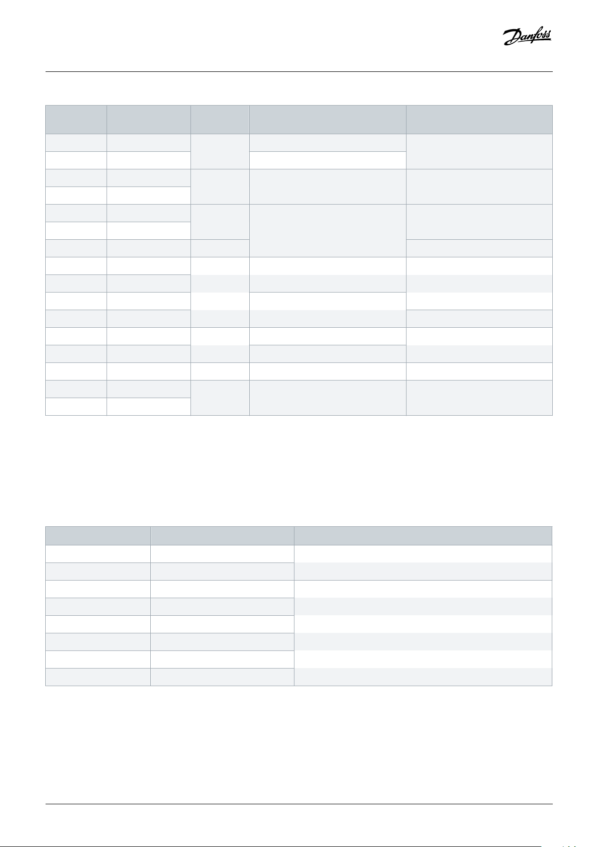
3.4 Current Ratings (IEC Ratings)
NO TI CE
Contact the local supplier for ratings under operating conditions not covered by these rating charts.
Illustration 2: AC53b Format
NO TI CE
All ratings are calculated at an altitude of 1000 m (3280 ft) and an ambient temperature of 40 °C (104 °F).
Table 2: In-line Installation, MCD6-0020B ~ MCD6-0042B
3.0-10:350 3.5-15:345 4.0-10:350 4.0-20:340 5.0-5:355
MCD6-0020B 24 20 19 16 17
MCD6-0034B 42 34 34 27 32
MCD6-0042B 52 42 39 35 34
Table 3: In-line Installation, MCD6-0063B ~ MCD6-0579B
3.0-10:590 3.5-15:585 4.0-10:590 4.0-20:580 5.0-5:595
MCD6-0063B 64 63 60 51 54
MCD6-0069B 69 69 69 62 65
MCD6-0086B 105 86 84 69 77
14 | Danfoss A/S © 2018.10
AQ262141844215en-000202 / 175R1174
Page 15
Operating Guide | VLT® Soft Starter MCD 600
3.0-10:590 3.5-15:585 4.0-10:590 4.0-20:580 5.0-5:595
MCD6-0108B 115 108 105 86 95
MCD6-0129B 135 129 126 103 115
MCD6-0144B 184 144 139 116 127
MCD6-0171B 200 171 165 138 150
MCD6-0194B 229 194 187 157 170
MCD6-0244B 250 244 230 200 202
MCD6-0287B 352 287 277 234 258
MCD6-0323B 397 323 311 263 289
MCD6-0410B 410 410 410 380 400
MCD6-0527B 550 527 506 427 464
MCD6-0579B 580 579 555 470 508
Table 4: Inside Delta Installation
System Design
3.0-10:350 3.5-15:345 4.0-10:350 4.0-20:340 5.0-5:355
MCD6-0020B 36 30 28 24 25
MCD6-0034B 63 51 51 40 48
MCD6-0042B 78 63 58 52 51
3.0-10:590 3.5-15:585 4.0-10:590 4.0-20:580 5.0-5:595
MCD6-0063B 96 94 90 76 81
MCD6-0069B 103 103 103 93 97
MCD6-0086B 157 129 126 103 115
MCD6-0108B 172 162 157 129 142
MCD6-0129B 202 193 189 154 172
MCD6-0144B 276 216 208 174 190
MCD6-0171B 300 256 247 207 225
MCD6-0194B 343 291 280 235 255
MCD6-0244B 375 366 345 300 303
MCD6-0287B 528 430 415 351 387
MCD6-0323B 595 484 466 394 433
MCD6-0410B 615 615 615 570 600
MCD6-0527B 825 790 759 640 696
MCD6-0579B 870 868 832 705 762
Danfoss A/S © 2018.10
AQ262141844215en-000202 / 175R1174 | 15
Page 16
4/T2
READY RUN
TRIP
LOCAL
Exit
Reset
Menu
Store
2/T1
6/T3
1/L1
3/L2
5/L3
READY RUN TRIP LOCAL
Exit
Reset
Menu
Store
VLT
®
Soft Starter
VLT
®
Soft Starter
A
B
C D
E
A
B
C
D
E
e77ha713.10
Operating Guide | VLT® Soft Starter MCD 600
3.5 Dimensions and Weight
System Design
Illustration 3: Dimensions, Frame Sizes S1 (Left) and S2 (Right)
Table 5: Dimensions and Weight
Width [mm (in)] Height [mm (in)] Depth [mm (in)] Weight [kg (lb)]
A B C D E
MCD6-0020B 152 (6.0) 92 (3.6) 336 (13.2) 307 (12.1) 231 (9.1) 4.8 (10.7)
MCD6-0034B
MCD6-0042B
MCD6-0063B 4.9 (10.9)
MCD6-0069B
MCD6-0086B 5.5 (12.1)
MCD6-0108B
MCD6-0129B
MCD6-0144B 216 (8.5) 180 (7.1) 495 (19.5) 450 (17.7) 243 (9.6) 12.7 (28)
MCD6-0171B
MCD6-0194B
MCD6-0244B 15.5 (34.2)
MCD6-0287B 523 (20.6)
MCD6-0323B
MCD6-0410B
MCD6-0527B 19 (41.9)
MCD6-0579B
16 | Danfoss A/S © 2018.10
AQ262141844215en-000202 / 175R1174
Page 17
4/T2
2/T1
6/T3
1/L1
3/L2
5/L3
4/T2
READY
RUN
TRIP
LOCAL
Exit
Reset
Menu
Store
2/T1
6/T3
1/L1
3/L2
5/L3
VLT
®
Soft Starter
4/T2
READY
RUN
TRIP
LOCAL
Exit
Reset
Menu
Store
2/T1 6/T3
1/L1 3/L2 5/L3
VLT
®
Soft Starter
4/T2
READY RUN TRIP
LOCAL
Exit
Reset
Menu
Store
2/T1 6/T3
1/L1
3/L2
5/L3
VLT
®
Soft Starter
4/T2
READY RUN TRIP LOCAL
Exit
Reset
Menu
Store
2/T1 6/T3
1/L1 3/L2 5/L3
VLT
®
Soft Starter
4/T2
READY RUN TRIP LOCAL
Exit
Reset
Menu
Store
2/T1 6/T3
1/L1 3/L2 5/L3
VLT
®
Soft Starter
177HA714.10
A
B
C
D D
C
Operating Guide | VLT® Soft Starter MCD 600
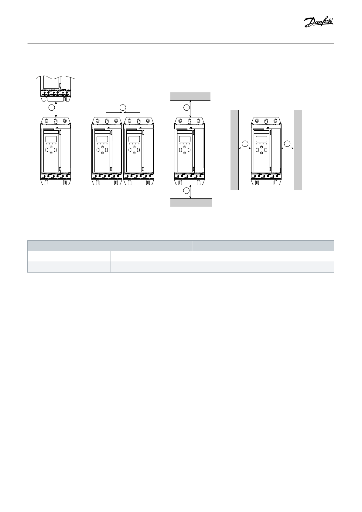
3.6 Physical Installation/Cooling Clearances
System Design
Illustration 4: Clearances
Table 6: Cooling Clearances
Clearance between soft starters Clearance to solid surfaces
A [mm (in)] B [mm (in)] C [mm (in)] D [mm (in)]
>100 (3.9) >10 (0.4) >100 (3.9) >10 (0.4)
3.7 Accessories
3.7.1 Expansion Cards
The VLT® Soft Starter MCD 600 offers expansion cards for users requiring additional inputs and outputs or advanced functionality. Each
MCD 600 can support a maximum of 1 expansion card.
3.7.1.1 Smart Card
The smart card has been designed to support integration with pumping applications and provides the following additional inputs and
outputs:
• 3 x digital inputs.
• 3 x 4–20 mA transducer inputs.
• 1 x RTD input.
• 1 x USB-B port.
• Remote LCP connector.
Ordering number: 175G0133
Danfoss A/S © 2018.10
AQ262141844215en-000202 / 175R1174 | 17
Page 18
Operating Guide | VLT® Soft Starter MCD 600
System Design
3.7.1.2 Communication Expansion Cards
The VLT® Soft Starter MCD 600 supports network communication via easy-to-install communication expansion cards. Each
communication card includes a remote LCP 601 connector port.
Table 7: Fieldbus Expansion Cards with Ordering Numbers
Option Card Ordering Number
VLT® Soft Starter MCD 600 Modbus RTU 175G0127
VLT® Soft Starter MCD 600 PROFIBUS 175G0128
VLT® Soft Starter MCD 600 DeviceNet 175G0129
VLT® Soft Starter MCD 600 Modbus TCP 175G0130
VLT® Soft Starter MCD 600 EtherNet/IP 175G0131
VLT® Soft Starter MCD 600 PROFINET 175G0132
VLT® Soft Starter MCD 600 Pump Application 175G0133
3.7.2 Remote LCP 601
The VLT® Soft Starter MCD 600 soft starters can be used with a remote LCP mounted up to 3 m (9.8 ft) away from the soft starter. Each
expansion card includes an LCP connection port, or a dedicated LCP connector card is available.
Ordering number for the Remote LCP 601 expansion card: 175G0134.
3.7.3 Finger Guard Kit
Finger guards may be specified for personal safety. Finger guards fit over the soft starter terminals to prevent accidental contact with
live terminals. Finger guards provide IP20 protection when used with cable of diameter 22 mm or greater.
Finger guards are compatible with models MCD6-0144B ~ MCD6-0579B.
Ordering number for the finger guard kit: 175G0186.
3.7.4 Soft Starter Management Software
The VLT® Soft Starter MCD 600 has an installed USB flash interface. The USB flash must be formatted to FAT32 format. To format the
flash, follow the instructions on a PC when connecting a standard flash stick (minimum 4 MB) to a USB port. VLT® Motion Control Tool
MCT 10 transfers the set-up files to the USB flash stick. To load the set-up files to the soft starter, use the LCP as described in 6.7.1 Save
and Load Procedure.
The VLT® Motion Control Tool MCT 10 can help manage the soft starter. Contact the local supplier for more information.
Documentation for the VLT® Motion Control Tool MCT 10 can be downloaded from www.danfoss.com/en/search/?filter=type
%3Adocumentation.
3.8 Main Contactor
A main contactor is recommended to protect the soft starter from voltage disturbances on the network while stopped. Select a
contactor with an AC3 rating greater than or equal to the FLC rating of the connected motor.
18 | Danfoss A/S © 2018.10
AQ262141844215en-000202 / 175R1174
Page 19
K1
K1
1
2
4
3
e77ha794.10
Operating Guide | VLT® Soft Starter MCD 600
Use the main contactor output (13, 14) to control the contactor.
For wiring of the main contactor, see illustration 12 in 5.8 Typical Installation.
System Design
WA RN IN G
SHOCK HAZARD
When the soft starter is wired in inside delta configuration, it results in a portion of the motor windings being connected to line
power at all times (even when the soft starter is switched off). This situation may cause death or serious personal injury.
Always install a main contactor or shunt trip circuit breaker when connecting the soft starter in inside delta configuration.
-
3.9 Circuit Breaker
A shunt trip circuit breaker may be used instead of a main contactor to isolate the motor circuit if a soft starter trips. The shunt trip
mechanism must be powered from the supply side of the circuit breaker or from a separate control supply.
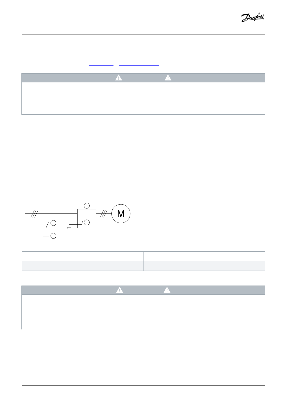
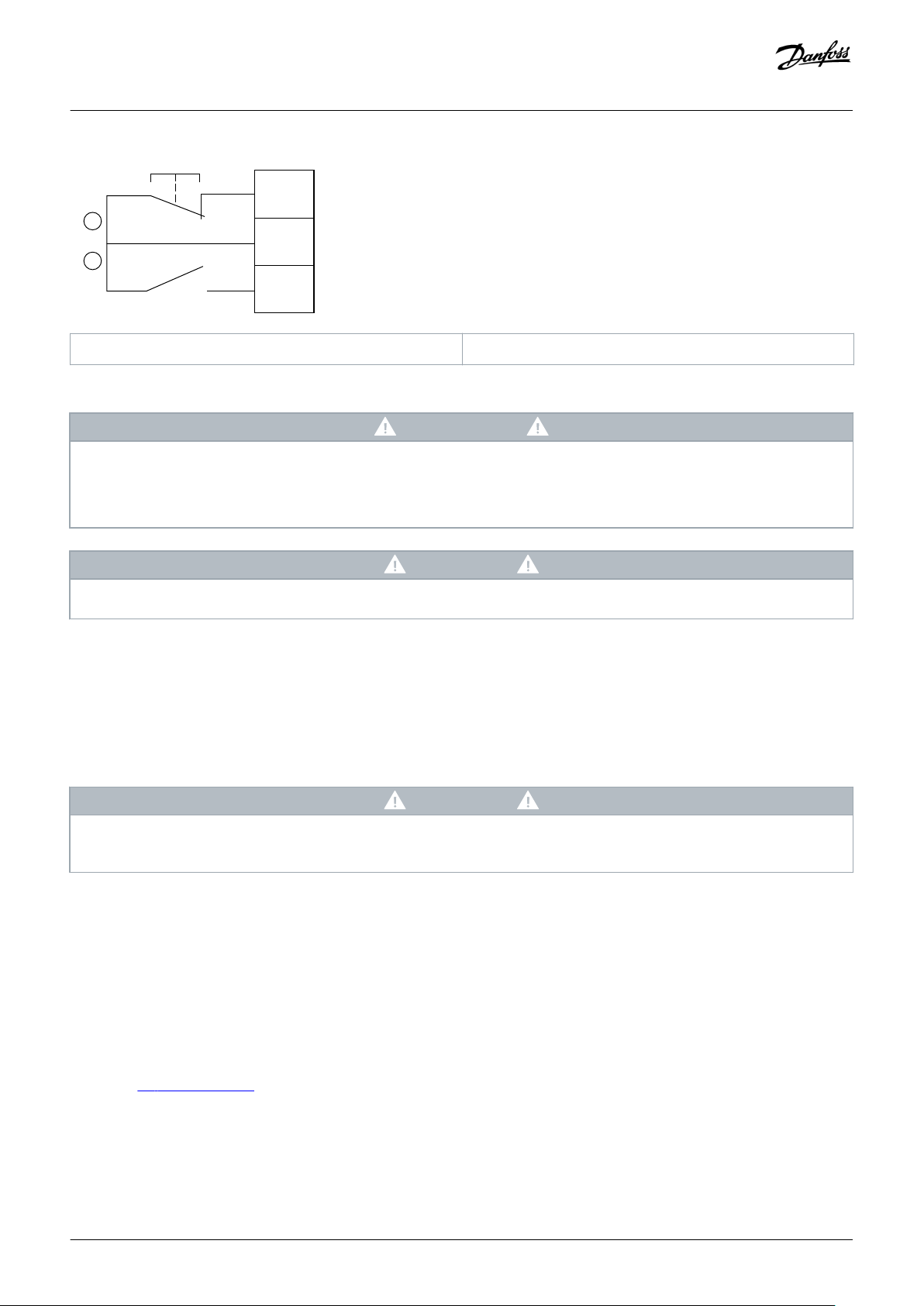
3.10 Power Factor Correction
If power factor correction is used, use a dedicated contactor to switch in the capacitors.
To use the VLT® Soft Starter MCD 600 to control power factor correction, connect the PFC contactor to a programmable relay set to
Run. When the motor reaches full speed, the relay closes and power factor correction is switched in.
1 Soft starter
3 Power factor correction contactor
Illustration 5: Connection Diagram
2 Programmable output (set=Run)
4 Power factor correction
CA UT IO N
EQUIPMENT DAMAGE
Connecting power factor correction capacitors to the output side damages the soft starter.
Always connect power factor correction capacitors to the input side of the soft starter.
-
Do not use the soft starter relay output to switch in power factor correction directly.
-
Danfoss A/S © 2018.10
AQ262141844215en-000202 / 175R1174 | 19
Page 20
Operating Guide | VLT® Soft Starter MCD 600
System Design
3.11 Short-circuit Protection Devices
When designing motor circuit protection schemes, the IEC 60947-4-1 standard on soft starters and contactors defines 2 types of
coordination regarding soft starters:
• Type 1 coordination.
• Type 2 coordination.
3.11.1 Type 1 Coordination
Type 1 coordination requires that, if there is a short circuit on the output side of a soft starter, the fault must be cleared without risk of
injury to personnel and damage to installations. There is no requirement that the soft starter must remain operational after the fault.
For the soft starter to become operational again, repair and replacement of parts are required.
HRC fuses (such as Ferraz/Mersen AJT fuses) can be used for Type 1 coordination according to the IEC 60947-4-2 standard.
3.11.2 Type 2 Coordination
Type 2 coordination requires that, if there is a short circuit on the output side of a soft starter, the fault must be cleared without risk of
injury to personnel or damage to the soft starter.
Type 2 coordination has the advantage that, after the fault is cleared, authorized personnel can replace the blown fuses and check
contactors for any welding. The soft starter is then operational again.
Semiconductor fuses for Type 2 circuit protection are extra to HRC fuses or MCCBs that form part of the motor branch circuit
protection.
CA UT IO N
DC BRAKE
A high brake torque setting can result in peak currents up to motor DOL being drawn while the motor is stopping.
Ensure that protection fuses installed in the motor branch circuit are selected appropriately.
-
CA UT IO N
NO BRANCH CIRCUIT PROTECTION
Integral solid-state short-circuit protection does not provide branch circuit protection.
Provide branch circuit protection in accordance with the National Electrical Code and any additional local codes.
-
3.12 IEC Coordination with Short-circuit Protection Devices
These fuses were selected based on a start current of 300% FLC for 10 s.
Table 8: IEC Fuses
Nominal rating [A]
MCD6-0020B 24 1150 40NHG000B 170M3010
20 | Danfoss A/S © 2018.10
SCR I2t (A2s)
Type 1 coordination 480 V AC, 65 kA
Bussmann NH fuse links
Type 2 coordination 690 V AC,
65 kA Bussmann DIN 43 653
AQ262141844215en-000202 / 175R1174
Page 21
Operating Guide | VLT® Soft Starter MCD 600
System Design
Nominal rating [A]
MCD6-0034B 42 7200 63NHG000B 170M3013
MCD6-0042B 52 80NHG000B
MCD6-0063B 64 15000 100NHG000B 170M3014
MCD6-0069B 69
MCD6-0086B 105 80000 160NHG00B 170M3015
MCD6-0108B 115
MCD6-0129B 135 125000 170M3016
MCD6-0144B 184 320000 250NHG2B 170M3020
MCD6-0171B 200
MCD6-0194B 229 315NHG2B
MCD6-0244B 250 170M3021
MCD6-0287B 352 202000 355NHG2B 170M6009
MCD6-0323B 397 400NHG2B
MCD6-0410B 410 320000 425NHG2B 170M6010
MCD6-0527B 550 781000 630NHG3B 170M6012
SCR I2t (A2s)
Type 1 coordination 480 V AC, 65 kA
Bussmann NH fuse links
Type 2 coordination 690 V AC,
65 kA Bussmann DIN 43 653
MCD6-0579B 579
3.13 UL Coordination with Short-circuit Protection Devices
3.13.1 Standard Fault Short-circuit Current Ratings
Suitable for use on a circuit capable of delivering not more than the stated level of amperes (symmetrical rms), 600 V AC maximum.
Table 9: Maximum Fuse Rating [A] - Standard Fault Short-Circuit Current
Model Nominal rating [A]
MCD6-0020B 24 5 kA
MCD6-0034B 42
MCD6-0042B 52 10 kA
MCD6-0063B 64
MCD6-0069B 69
MCD6-0086B 105
MCD6-0108B 120
MCD6-0129B 135
3 cycle short cct rating @600 V AC
(1)
Danfoss A/S © 2018.10
AQ262141844215en-000202 / 175R1174 | 21
Page 22
Operating Guide | VLT® Soft Starter MCD 600
System Design
Model Nominal rating [A]
3 cycle short cct rating @600 V AC
(1)
MCD6-0144B 184 18 kA
MCD6-0171B 225
MCD6-0194B 229
MCD6-0244B 250
MCD6-0287B 352
MCD6-0323B 397
MCD6-0410B 410 30 kA
MCD6-0527B 550
MCD6-0579B 580
1
Suitable for use in a circuit with the prospective current noted, when protected by any listed fuses or listed circuit breakers sized according to the NEC.
3.13.2 High Fault Short-circuit Current Ratings
Table 10: Maximum Fuse Rating [A] - High Fault Short-circuit Current
Model Nominal rating [A] Short cct rating @480 V AC maximum
Listed fuse rating [A]
(1)
Fuse class
MCD6-0020B 24 65 kA 30 Any (J, T, K-1, RK1, RK5)
(1)
MCD6-0034B 42 50
MCD6-0042B 52 60
MCD6-0063B 64 80
MCD6-0069B 69 80
MCD6-0086B 105 125 J, T, K-1, RK1
MCD6-0108B 115 125
MCD6-0129B 135 150
MCD6-0144B 184 200 J, T
MCD6-0171B 200 225
MCD6-0194B 229 250
MCD6-0244B 250 300
MCD6-0287 352 400 Any (J, T, K-1, RK1, RK5)
MCD6-0323B 397 450
MCD6-0410B 410 450
MCD6-0527B 550 600
MCD6-0579B 580 600
1
Suitable for use on a circuit capable of delivering not more than 65000 rms symmetrical amperes, 480 V AC maximum, when protected by fuses of the stated class and rating.
22 | Danfoss A/S © 2018.10
AQ262141844215en-000202 / 175R1174
Page 23
Operating Guide | VLT® Soft Starter MCD 600
Table 11: Circuit Breakers - High Fault Short-circuit Current
System Design
Model Nominal rating [A]
Breaker 1: Eaton (rating, A)
(1)
Breaker 2: GE (rating, A)
(1)
Breaker 3: LS (rating, A)
MCD6-0020B 24 HFD3030 (30 A) SELA36AT0060 (60 A) UTS150H-xxU-040 (40 A)
MCD6-0034B 42 HFD3050 (50 A) UTS150H-xxU-050 (50 A)
MCD6-0042B 52 HFD3060 (60 A) UTS150H-xxU-060 (60 A)
MCD6-0063B 64 HFD3100 (100 A) SELA36AT0150 (150 A) UTS150H-xxU-100 (100 A)
MCD6-0069B 69
MCD6-0086B 105 HFD3125 (125 A) UTS150H-xxU-125 (125 A)
MCD6-0108B 115
MCD6-0129B 135 HFD3150 (150 A) UTS150H-xxU-150 (150 A)
MCD6-0144B 184 HFD3250 (250 A) SELA36AT0250 (250 A) UTS150H-xxU-250 (250 A)
MCD6-0171B 200
MCD6-0194B 229
MCD6-0244B 250 HFD3300 (300 A) SELA36AT0400 (400 A) UTS150H-xxU-300 (300 A)
MCDF6-0287B 352 HFD3400 (400 A) SELA36AT0600 (600 A) UTS150H-xxU-400 (400 A)
MCD6-0323B 397
MCD6-0410B 410 HFD3600 (600 A) UTS150H-xxU-600 (600 A)
MCD6-0527B 550 UTS150H-xxU-800 (800 A)
(1) (2)
MCD6-0579B 580 UTS150H-NG0-800
1
Suitable for use on a circuit capable of delivering not more than 65000 rms symmetrical amperes, 480 V AC maximum, when protected by circuit breaker models listed in this table.
2
For LS circuit breakers, xx represents FM, FT, or AT.
3.14 Fuse Selection for Type 2 Coordination
Type 2 coordination is achieved by using semiconductor fuses. These fuses must be able to carry motor start current and have a total
clearing I2t less than the I2t of the soft starter SCRs.
When selecting semiconductor fuses for VLT® Soft Starter MCD 600, use the I2t values in table 12.
For further information on selecting semiconductor fuses, contact the local distributor.
Table 12: SCR Values for Semiconductor Fuses
Model
MCD6-0020B 1150
MCD6-0034B 7200
MCD6-0042B
MCD6-0063B 15000
SCR I2t [A2s]
MCD6-0069B
Danfoss A/S © 2018.10
AQ262141844215en-000202 / 175R1174 | 23
Page 24

Operating Guide | VLT® Soft Starter MCD 600
System Design
Model
MCD6-0086B 80000
MCD6-0108B
MCD6-0129B 125000
MCD6-0144B 320000
MCD6-0171B
MCD6-0194B
MCD6-0244B
MCD6-0287B 202000
MCD6-0323B
MCD6-0410B 320000
MCD6-0527B 781000
MCD6-0579B
SCR I2t [A2s]
24 | Danfoss A/S © 2018.10
AQ262141844215en-000202 / 175R1174
Page 25

Operating Guide | VLT® Soft Starter MCD 600
Specifications
4 Specifications
4.1 Supply
Mains voltage (L1, L2, L3)
MCD6-xxxxB-T5 200–525 V AC (±10%)
MCD6-xxxxB-T7 380–690 V AC (±10%)
Control voltage (A7, A8, A9)
MCD6-xxxxB-xx-CV2 (A8, A9) 110–120 V AC (+10%/-15%), 600 mA
MCD6-xxxxB-xx-CV2 (A7, A9) 220–240 V AC (+10%/-15%), 600 mA
MCD6-xxxxB-xx-CV1 (A8, A9) 24 V AC/V DC (±20%), 2.8 A
Mains frequency 50–60 Hz (±5 Hz)
Rated insulation voltage 690 V AC
Rated impulse withstand voltage 6 kV
Form designation Bypassed or continuous, semiconductor motor starter form 1
4.2 Short-circuit Capability
Coordination with semiconductor fuses Type 2
Coordination with HRC fuses Type 1
4.3 Electromagnetic Capability (Compliant with EU Directive 2014/35/EU)
EMC Immunity IEC 60947-4-2
EMC Emmissions IEC 60947-4-2 Class B
4.4 Inputs
Input rating Active 24 V DC, 8 mA approximately
Motor thermistor (TER-05, TER-06) Trip >3.6 kΩ, reset >1.6 kΩ
4.5 Outputs
Relay outputs 10 A @ 250 V AC resistive, 5 A @ 250 V AC AC15 pf 0.3
Main contactor (13, 14) Normally open
Relay output A (21, 22, 23) Changeover
Relay output B (33, 34) Normally open
Analog output (AO-07, AO-08)
Maximum load 600 Ω (12 V DC @ 20 mA)
Accuracy ±5%
Danfoss A/S © 2018.10
AQ262141844215en-000202 / 175R1174 | 25
Page 26

Operating Guide | VLT® Soft Starter MCD 600
Specifications
4.6 Environmental
Operating temperature -10 to +60 °C (14–140 °F), above 40 °C (104 °F) with derating
Storage temperature -25 to +60 °C (-13 to +140 °F)
Operating altitude 0–1000 m (0–3280 ft), above 1000 m (3280 ft) with derating
Humidity 5–95% relative humidity
Pollution degree Pollution degree 3
Vibration IEC 60068-2-6
Protection
MCD6-0020B~MCD6-0129B IP20
MCD6-0144B~MCD6-0579B IP00
4.7 Heat Dissipation
During start 4.5 W per ampere
During run
MCD6-0020B~MCD6-0042B ≤ 35 W approximately
MCD6-0063B~MCD6-0129B ≤ 50 W approximately
MCD6-0144B~MCD6-0244B ≤ 120 W approximately
MCD6-0287B~MCD6-0579B ≤ 140 W approximately
4.8 Motor Overload Protection
The default settings of parameters 1-4 to 1-6 provide motor overload
protection.
Class 10, trip current 105% of FLA (full load amperage) or
equivalent
4.9 Certification
CE EN 60947-4-2
UL/C-UL UL 508
Marine Lloyds Marine No 1 specification
ABS
DNV
4.10 Operational Life (Internal Bypass Contacts)
Expected operational lifetime 100000 operations
26 | Danfoss A/S © 2018.10
AQ262141844215en-000202 / 175R1174
Page 27

Operating Guide | VLT® Soft Starter MCD 600
Installation
5 Installation
5.1 Safety Instructions
See 2.3 Safety Precautions for general safety instructions.
WA RN IN G
INDUCED VOLTAGE
Induced voltage from output motor cables that run together can charge equipment capacitors, even with the equipment
turned off and locked out. Failure to run output motor cables separately or to use shielded cables could result in death or
serious injury.
Run output motor cables separately.
-
Use shielded cables.
-
WA RN IN G
UNINTENDED START
When the soft starter is connected to AC mains, DC supply, or load sharing, the motor can start at any time. Unintended start
during programming, service, or repair work can result in death, serious injury or property damage. The motor can start with an
external switch, a fieldbus command, an input reference signal from the LCP, or after a cleared fault condition.
Press [Off/Reset] on the LCP before programming parameters.
-
Disconnect the soft starter from the mains.
-
Completely wire and assemble the soft starter, motor, and any driven equipment before connecting the soft starter to AC
-
mains, DC supply, or load sharing.
Fit the power supply to the soft starter with an isolating switch and a circuit-breaking device (for example a power
-
contactor) controllable through an external safety system (for example an emergency stop or a fault detector).
5.2 Command Source
Start and stop the soft starter via the digital inputs, remote LCP 601, communication network, smart card, or scheduled auto-start/stop.
Set up the command source via Set-up Tools or via parameter 1-1 Command Source.
If the remote LCP is installed, the [CMD/Menu] key provides shortcut access to the Command Source function in Set-up Tools.
Danfoss A/S © 2018.10
AQ262141844215en-000202 / 175R1174 | 27
Page 28
Operating Guide | VLT® Soft Starter MCD 600
5.3 Setting up the Soft Starter
Procedure
1. Mount the soft starter, see 3.6 Physical Installation/Cooling Clearances.
2. Connect control wiring, see 5.4.1 Input Terminals.
3. Apply control voltage to the soft starter.
4. Configure the application (listed in the Quick Set-up):
A Press [Menu].
B Press [Menu/Store] to open the Quick Set-up menu.
C Scroll through the list to find the application.
D Press [Menu/Store] to begin the configuration process, see
5. Configure the application (not listed in the Quick Set-up):
A Press [Back] to return to the Menu.
B Press [▿] to scroll to the Main Menu and press [Menu/Store].
C Scroll to Motor Details, press [Menu/Store] twice, and edit parameter 1-2 Motor Full Load Current.
D Set parameter 1-2 Motor Full Load Current to match the motor full load current (FLC).
E Press [Menu/Store] to save the setting.
6. Press [Back] repeatedly to close the Main Menu.
7. (Optional) Use the built-in simulation tools to check that the control wiring is connected correctly, see
8. Power off the soft starter.
9. Connect the motor cables to the soft starter output terminals 2/T1, 4/T2, 6/T3.
10. Connect mains supply cables to the soft starter input terminals 1/L1, 3/L2, 5/L3, see
The soft starter is now ready to control the motor.
5.9 Quick Set-up.
5.7 Power Terminations.
Installation
6.5 Run Simulation.
5.4 Inputs
CA UT IO N
The control inputs are powered by the soft starter. Do not apply external voltage to the control input terminals.
NO TI CE
Cables to the control inputs must be segregated from mains voltage and motor cabling.
28 | Danfoss A/S © 2018.10
AQ262141844215en-000202 / 175R1174
Page 29
READY
RUN
TRIP
LOCAL
Exit
Reset
Menu
Store
VLT
®
Soft Starter
2/T1
4/T2
6/T3
1/L1 3/L2
5/L3
AO-08
AO-07
DI-B
DI-A
COM+
START
COM+
RESET
TER-06
TER-05
e77ha718.10
Operating Guide | VLT® Soft Starter MCD 600
5.4.1 Input Terminals
Installation
TER-05, TER-06 Motor thermistor input
START, COM+ Start/stop input
DI-B, COM+ Programmable input B (default = Input trip (N/O))
RESET, COM+ Reset input
DI-A, COM+ Programmable input A (default = Input trip (N/O))
USB port (for flash, no direct PC connection)
Illustration 6: Input Terminals
5.4.2 Motor Thermistor
Motor thermistors can be connected directly to the VLT® Soft Starter MCD 600. The soft starter trips when the resistance of the
thermistor circuit exceeds approximately 3.6 kΩ or drops below 20 Ω.
The thermistors must be wired in series. The thermistor circuit should be run in shielded cable and must be electrically isolated from
ground and all other power and control circuits.
The thermistor input is disabled by default, but activates automatically when a thermistor is detected. If thermistors have
previously been connected to the MCD 600 but are no longer required, use the Thermistor Reset function to disable the
thermistor. Thermistor reset is accessed via Set-up Tools.
5.4.3 Start/Stop
NO TI CE
The VLT® Soft Starter MCD 600 requires 2-wire control.
Danfoss A/S © 2018.10
AQ262141844215en-000202 / 175R1174 | 29
Page 30
RESET
COM+
START
A
B
e77ha721.10
Operating Guide | VLT® Soft Starter MCD 600
A Reset B Start/stop
Illustration 7: Start/Stop Control Wiring
CA UT IO N
ATTEMPTED START
If the start input is closed when control voltage is applied, the soft starter attempts to start.
Check that the start/stop input is open before applying control voltage.
-
Installation
NO TI CE
The MCD 600 only accepts command from the control inputs if parameter 1-1 Command Source is set to Digital Input.
5.4.4 Reset/Starter Disable
The reset input (RESET, COM+) is normally closed by default. The soft starter does not start if the reset input is open. The display then
shows Not ready.
If the reset opens while the soft starter is running, the soft starter removes power and allows the motor to coast to stop.
NO TI CE
The reset input can be configured for normally open or normally closed operation. Make the selection in parameter 7-9 Reset/
Enable Logic.
5.4.5 Programmable Inputs
The programmable inputs (DI-A, COM+ and DI-V, COM+) allow external equipment to control the soft starter. The operation of the
programmable inputs is controlled by parameters 7-1 to 7-8.
5.4.6 USB Port
The USB port can be used to upload a configuration file, or download parameter settings and event log information from the soft
starter. See 6.7 USB Save & Load for details.
30 | Danfoss A/S © 2018.10
AQ262141844215en-000202 / 175R1174
Page 31

READY
RUN
TRIP
LOCAL
Exit
Reset
Menu
Store
VLT
®
Soft Starter
2/T1
4/T2
6/T3
1/L1 3/L2
5/L3
AO-08
AO-07
DI-B
DI-A
COM+
START
COM+
RESET
TER-06
TER-05
34
33
23
22
21
14
13
e77ha719.10
Operating Guide | VLT® Soft Starter MCD 600
5.5 Outputs
5.5.1 Output Terminals
Installation
AO-07, AO-08 Analog output
21, 22, 23 Relay output A (default = Run)
13, 14 Main contactor output
33, 34 Relay output B (default = Run)
Illustration 8: Output Terminals
5.5.2 Analog Output
The VLT® Soft Starter MCD 600 has an analog output, which can be connected to associated equipment to monitor motor
performance. The operation of the analog output is controlled by parameters 9-1 to 9-4.
5.5.3 Main Contactor Output
The main contactor output (13, 14) closes as soon as the soft starter receives a start command and remains closed while the soft starter
is controlling the motor (until the motor starts a coast to stop, or until the end of a soft stop). The main contactor output also opens if
the soft starter trips.
Some electronic contactor coils are not suitable for direct switching with PCB mount relays. Consult the contactor
manufacturer/supplier to confirm suitability.
NO TI CE
Danfoss A/S © 2018.10
AQ262141844215en-000202 / 175R1174 | 31
Page 32

READY RUN TRIP LOCAL
Exit
Reset
Menu
Store
VLT
®
Soft Starter
2/T1 4/T2 6/T3
1/L1 3/L2 5/L3
A9
A8
A7
e77ha720.10
Operating Guide | VLT® Soft Starter MCD 600
Installation
5.5.4 Programmable Outputs
The programmable outputs (21, 22, 23 and 33, 34) can report the status of the soft starter or can control associated equipment.
The operation of the programmable outputs is controlled by parameters 8-1 to 8-6.
5.6 Control Voltage
5.6.1 Control Voltage Terminals
Illustration 9: Control Voltage Terminals
Connect the control supply according to the supply voltage being used.
• MCD6-xxxxB-xx-CV2 (110–120 V AC): A8, A9.
• MCD6-xxxxB-xx-CV2 (220–240 V AC): A7, A9.
• MCD6-xxxxB-xx-CV1 (24 V AC/V DC): A8, A9.
5.6.2 UL Compliant Installation
For MCD6-0144B to MCD6-0579B to be UL-compliant, supplementary or branch circuit overcurrent protection must be used on the
control circuit supply (A7, A8, A9) in accordance with the electrical code applicable at the installation location.
32 | Danfoss A/S © 2018.10
AQ262141844215en-000202 / 175R1174
Page 33

e77ha646.11
e77ha648.11
e77ha647.11
e77ha649.11
6 mm
0.24 in
10 mm
0.4 in
20 mm
0.8 in
9 mm
(M8)
e77ha722.10
6 mm
0.24 in
17 mm
0.7 in
34 mm
1.7 in
13 mm
(M12)
e77ha723.10
Operating Guide | VLT® Soft Starter MCD 600
Installation
5.7 Power Terminations
WA RN IN G
SHOCK HAZARD
Models MCD6-0144B ~ MCD6-0579B are IP00 and pose a risk of electrical shock if touching the terminals.
Install a finger guard kit on the soft starter.
-
Install the soft starters inside an enclosure.
-
The power input and output terminals for VLT® Soft Starter MCD 600 are at the bottom of the unit.
• Models MCD6-0020B~MCD6-0129B use cage clamps. Use copper stranded or solid conductors rated for 75 °C (167 °F) or higher.
• Models MCD6-0144B~MCD6-0579B use busbars. Use copper or aluminum conductors, stranded or solid, rated for 60/75 °C
(140/167 °F).
NO TI CE
Some units use aluminum busbars. When connecting power terminations, clean the surface contact area thoroughly (using an
emery or stainless steel brush) and use an appropriate jointing compound to prevent corrosion.
Table 13: Power Terminations, MCD6-0020B~MCD6-0129B
MCD6-0020B~MCD6-0129B
Cable size: 6–
2
70 mm
(AWG 10–2/0)
Torque: 4 Nm
(2.9 ft-lb)
14 mm (0.55 in)
Table 14: Power Terminations, MCD6-0144B~MCD6-0244B and MCD6-0287B~MCD6-0579B
MCD6-0144B~MCD6-0244B MCD6-0287B~MCD6-0579B
19 Nm (14 ft-lb)
Torx T20 x 150
Flat 7 mm x
150
66 Nm (49 ft-lb)
Danfoss A/S © 2018.10
AQ262141844215en-000202 / 175R1174 | 33
Page 34

Operating Guide | VLT® Soft Starter MCD 600
Installation
NO TI CE
If the installation requires large diameter cables, it is possible to complete each termination with 2 smaller cables, 1 on each
side of the busbar.
5.7.1 Wiring Connectors
Select a connector according to the wire size, material, and application requirements.
For models MCD6-0144B to MCD6-0579B, a compression connector is recommended. The recommended crimping tool is TBM8-750.
Table 15: Recommended Lugs
Model Example connector - aluminum cable Example connector - copper cable
MCD6-0144B 61162 60150
MCD6-0171B 61165 60156
MCD6-0194B 61171 60165
MCD6-0244B
MCD6-0287B 61162 60150
MCD6-0352B 61165 60156
MCD6-0410B 60156
MCD6-0527B 61178 60171
MCD6-0579B
5.7.2 Motor Connection
The VLT® Soft Starter MCD 600 can be connected to the motor in-line or inside delta (also called 3-wire and 6-wire connection). When
connecting in inside delta, enter the FLC for parameter 1-2 Motor Full Load Current. The MCD 600 automatically detects whether the
motor is connected in-line or inside delta and calculates the correct inside delta current level.
NO TI CE
If the soft starter is not detecting the motor connection correctly, use parameter 20-6 Motor Connection.
34 | Danfoss A/S © 2018.10
AQ262141844215en-000202 / 175R1174
Page 35

e77ha726.10
14
13
K1
K1F1
6/T3
2/T1
5/L3
3/L2
1/L1
4/T2
M
3
M
3
U1(1) U2(4)
V1(2)
V2(5)
W1(3) W2(6)
K1
F1
e77ha727.10
14
13
K1
6/T3
2/T1
5/L3
3/L2
1/L1
4/T2
Operating Guide | VLT® Soft Starter MCD 600
5.7.2.1 In-line Installation
Installation
K1 Main contactor (strongly recommended)
13, 14 Main contactor output
Not using fuses or circuit breakers voids the guarantee.
Illustration 10: Wiring of an In-line Installation
5.7.2.2 Inside Delta Installation
F1
Fuses or circuit breaker (optional
()
)
K1 Main contactor F1
Danfoss A/S © 2018.10
Fuses or circuit breaker (optional
AQ262141844215en-000202 / 175R1174 | 35
()
)
Page 36

22
21
6/T3
2/T1
13
14
4/T2
44
33
23
AO-07
AO-08
TER-06
TER-05
START
COM+
DI-A
DI-B
COM+
A9
A8
A7
5/L3
3/L2
RESET
1/L1
F1
S1
S2
K1
K1
(L/+) (N/# )
A
#
+
M
7
6
5
3
2
1
10
4
9
8
e77ha728.10
Operating Guide | VLT® Soft Starter MCD 600
Installation
13, 14 Main contactor output
Not using fuses or circuit breakers voids the guarantee.
Illustration 11: Wiring of an Inside Delta Installation
5.8 Typical Installation
The VLT® Soft Starter MCD 600 is installed with a main contactor (AC3-rated). Control voltage must be supplied from the input side of
the contactor.
The main contactor is controlled by the main contactor output (13, 14).
1 Three-phase supply
3 Control voltage (soft starter)
2 Motor
4 Digital inputs
36 | Danfoss A/S © 2018.10
AQ262141844215en-000202 / 175R1174
Page 37

Operating Guide | VLT® Soft Starter MCD 600
Installation
5 Motor thermistor input
7 Analog output
9 Pilot lamps
K1 Main contactor
RESET, COM+ (S1) Reset
DI-A, COM+ Programmable input A (default = Input trip (N/O))
TER-05, TER-06 Motor thermistor input
21, 22, 23 Relay output A (default = Run)
AO-07, AO-08 Analog output
Illustration 12: Installation Example
6 Relay outputs
8 Control voltage (external equipment)
10 Communications/smart card expansion port
F1 Semiconductor fuses
START, COM+ (S2) Start/stop
DI-B, COM+ Programmable input B (default = Input trip (N/O))
13, 14 Main contactor output
33, 34 Relay output B (default = Run)
5.9 Quick Set-up
The Quick Set-up makes it easy to configure the soft starter for common applications. The VLT® Soft Starter MCD 600 guides through
the most common installation parameters and suggests a typical setting for the application. Adjust each parameter to suit the exact
requirements.
All other parameters remain at default values. To change other parameter values or review default settings, use the Main Menu (see
10.4 Parameter List for details).
Always set parameter 1-2 Motor Full Load Current to match the motor nameplate FLC.
Table 16: Suggested Settings for Common Applications
Application Start mode Start
ramp
time [s]
Pump centrifugal
Pump bore Adaptive con-
Pump hydraul-icConstant cur-
Fan damped Constant cur-
Fan undamped Constant cur-
Compressor
screw
Compressor recip
Adaptive control
trol
rent
rent
rent
Constant current
Constant current
10 200 500 Early acceler-
3 200 500 Early acceler-
2 200 350 n/a Coast to stop n/a n/a
2 200 350 n/a Coast to stop n/a n/a
2 200 450 n/a Coast to stop n/a n/a
2 200 400 n/a Coast to stop n/a n/a
2 200 450 n/a Coast to stop n/a n/a
Initial
current
[%]
Current
limit
[%]
Adaptive
start profile
ation
ation
Stop mode Stop
time [s]
Adaptive
control
Adaptive
control
15 Late deceler-
3 Late deceler-
Adaptive
stop profile
ation
ation
Conveyor Constant cur-
rent
Danfoss A/S © 2018.10
5 200 450 n/a Coast to stop n/a n/a
AQ262141844215en-000202 / 175R1174 | 37
Page 38

Operating Guide | VLT® Soft Starter MCD 600
Installation
Application Start mode Start
ramp
time [s]
Bow thruster Constant cur-
rent
Bandsaw Constant cur-
rent
5 100 400 n/a Coast to stop n/a n/a
2 200 450 n/a Coast to stop n/a n/a
Initial
current
[%]
Current
limit
[%]
Adaptive
start profile
Stop mode Stop
time [s]
Adaptive
stop profile
NO TI CE
The adaptive start and stop profile settings only apply when using adaptive control. The settings are ignored for all other start
and stop modes.
38 | Danfoss A/S © 2018.10
AQ262141844215en-000202 / 175R1174
Page 39

Operating Guide | VLT® Soft Starter MCD 600
Set-up Tools
6 Set-up Tools
6.1 Introduction
Set-up Tools includes options to load or save parameters to a backup file, set the soft starter's network address, check the status of the inputs and outputs, reset the thermal models, or test operation using the Run Simulation.
To access Set-up Tools, press [Menu] to open the Main Menu and then select Set-up Tools.
6.2 Setting Date and Time
Procedure
1. Press [Menu] to open the menu.
2. Select Set-up Tools.
3. Scroll to Set Date & Time.
4. Press [Menu/Store] to enter edit mode.
5. Press [Menu/Store] and [Back] to select which part of the date or time to edit.
6. Press [▵] and [▿] to change the values.
7. Press [Menu/Store] after the last digit to save the setting.
When the action has been completed, the screen briefly shows a confirmation message, then returns to the previous menu level.
6.3 Command Source
Start and stop the soft starter via the digital inputs, remote LCP 601, communication network, smart card, or scheduled auto-start/stop.
Set up the command source via Set-up Tools or via parameter 1-1 Command Source.
If the remote LCP is installed, the [CMD/Menu] key provides shortcut access to the Command Source function in Set-up Tools.
6.4 Commissioning
Commissioning allows starting and stopping the soft starter via the LCP. Press [▵] [▿] to select a function, then press [Menu/Store] to
send the selected command to the soft starter. The available functions are:
• Quick stop (coast to stop)/reset.
• Start.
• Stop.
6.5 Run Simulation
Context:
The Run Simulation simulates a motor starting, running, and stopping to confirm that the soft starter and associated equipment have
been installed correctly.
NO TI CE
Disconnect the soft starter from mains voltage when using simulation mode.
Danfoss A/S © 2018.10
AQ262141844215en-000202 / 175R1174 | 39
Page 40

e77ha731.10
Run Simulation
Ready
Apply Start Signal
Operating Guide | VLT® Soft Starter MCD 600
The simulation is only available when the soft starter is in ready state.
Procedure
1. Press [Menu] and select Set-up Tools.
2. Scroll to Run Simulation and press [Menu/Store].
3. Apply a start command from the selected command source.
The soft starter simulates its prestart checks and closes the main contactor relay. The Run LED flashes.
NO TI CE
If mains voltage is connected, an error message is shown.
Set-up Tools
4. Press [Menu/Store].
The soft starter simulates starting. The Run LED flashes.
5. Press Menu/Store.
The soft starter simulates running.
6. Apply a stop command from the selected command source.
The soft starter simulates stopping. The Run LED flashes.
7. Press [Menu/Store].
The Ready LED flashes and the main contactor relay opens.
8. Press [Menu/Store].
The soft starter activates then deactivates each programmable output.
9. Press [Menu/Store].
The soft starter returns to the Set-up Tools.
6.6 Load/Save Settings
Context:
The Load/Save Settings allows:
• Resetting the soft starter parameters to default values.
• Loading parameter settings from an internal file.
• Saving the current parameter settings to an internal file.
The internal file contains default values until a user file is saved.
40 | Danfoss A/S © 2018.10
AQ262141844215en-000202 / 175R1174
Page 41

e77ha732.10
Load/Save Settings
Load Defaults
Load User Set
Save User Set
Operating Guide | VLT® Soft Starter MCD 600
Set-up Tools
Procedure
1. Press [Menu] and select Set-up Tools.
2. Scroll to Load/Save Settings and press [Menu/Store].
3. Scroll to the required function and press [Menu/Store].
4. At the confirmation prompt, select Yes to confirm or No to cancel.
5. Press [Menu/Store] to proceed.
When the action has been completed, the screen birefly shows a confirmation message, then returns to the previous menu level.
6.7 USB Save & Load
The USB Save & Load menu allows:
• Saving parameter settings and all event log entries to an external file (CSV format).
• Saving parameter settings to an external file (proprietary format).
• Loading parameter settings from a previously saved external file.
• Loading custom messages to show on the LCP when a programmable input is active.
NO TI CE
The VLT® Soft Starter MCD 600 supports FAT32 file systems. The MCD 600 USB functions are not compatible with NTFS file
systems.
Danfoss A/S © 2018.10
AQ262141844215en-000202 / 175R1174 | 41
Page 42

e77ha733.10
USB Save & Load
Save Params and Logs
Save Master Params
Load Master Params
Operating Guide | VLT® Soft Starter MCD 600
Set-up Tools
6.7.1 Save and Load Procedure
Procedure
1. Connect the external drive to the USB port.
2. Press [Menu] and select Set-up Tools.
3. Scroll to USB Save & Load and press [Menu/Store].
4. Scroll to the required function and press [Menu/Store].
5. At the confirmation prompt, select Yes to confirm or No to cancel.
6. Press [Menu/Store] to proceed.
When the action has been completed, the screen briefly shows a confirmation message, then returns to the previous menu level.
6.7.2 File Locations and Formats
Save parameters and logs
The soft starter creates a directory at the top level of the USB drive, named with the soft starter serial number. The event log and
parameter settings are saved as individual CSV files, and the soft starter's software and system information are saved to a text file.
Save master parameters
The soft starter creates a file called Master_Parameters.par and stores it on the USB drive.
Load master parameters
The soft starter loads the file Master_Parameters.par from the top level of the USB drive. The files can be created or edited using VLT®
Motion Control Tool MCT 10. Download the MCT 10 tool from www.danfoss.com/en/service-and-support/downloads/dds/vlt-motioncontrol-tool-mct-10/.
Load custom message
The soft starter loads the files Custom_Message_A.txt and Custom_Message_B.txt from the top level of the USB drive.
42 | Danfoss A/S © 2018.10
AQ262141844215en-000202 / 175R1174
Page 43

e77ha730.10
e77ha734.10
Auto-Start/Stop
Start/Stop Mode
Start/Stop Sunday
Start/Stop Monday
Operating Guide | VLT® Soft Starter MCD 600
Illustration 13: USB Directory
Set-up Tools
6.8 Auto-start/Stop
Context:
The soft starter can be configured to automatically start and/or stop the motor at a particular time, or run it in cycles of a specified
duration.
The Auto-Start/Stop function in Set-up Tools gives quick access to the auto-start/stop parameters.
Procedure
1. Press [Menu] and select Set-up Tools.
2. Scroll to Auto-Start/Stop and press [Menu/Store].
3. Scroll to the desired function and press [Menu/Store].
4. Adjust the settings as required:
A Press [Menu/Store] and [Back] to select which information to edit.
B Press [▵] [▿] to change the value.
Press [Menu/Store] to save changes. The soft starter confirms the changes.
Press [Back] to cancel the changes.
6.9 Network Address
To use the VLT® Soft Starter MCD 600 on an Ethernet network, separate addresses must be configured for:
Danfoss A/S © 2018.10
AQ262141844215en-000202 / 175R1174 | 43
Page 44

e77ha735.10
Set IP Address
192.168.000.002
e77ha711.10
Digital I/O State
Inputs: 0100
Outputs: 100
Operating Guide | VLT® Soft Starter MCD 600
• IP address.
• Gateway address.
• Subnet mask.
6.9.1 Setting a Network Address
Procedure
1. Press [Menu] and select Set-up Tools.
2. Scroll to Network Address and press [Menu/Store].
3. Scroll to the required function and press [Menu/Store].
Set-up Tools
4. The 1st digit of the address is highlighted.
5. Press [Back] and [Menu/Store] to select which digit to alter.
6. Press [▵] [▿] to change the value.
7. Press [Menu/Store] after the last digit to save the setting.
When the action has completed, the screen briefly shows a confirmation message, then returns to the previous menu level.
NO TI CE
The network address can also be set by using parameters 12-8 to 12-19.
NO TI CE
To configure the soft starter for use with other communication protocols, use parameters 12-1 to 12-7.
6.10 Digital I/O State
Illustration 14: Digital I/O Status Screen
44 | Danfoss A/S © 2018.10
AQ262141844215en-000202 / 175R1174
Page 45

AO-08
AO-07
DI-B
DI-A
COM+
START
COM+
RESET
TER-06
TER-05
3433232221
14
13
e77ha717.10
7
6
5
4
32
1
e77ha736.10
Analog I/O State
Thermistor: 0
4-20 mA Output: 04.0 mA
Operating Guide | VLT® Soft Starter MCD 600
Set-up Tools
1 RESET, COM+: Reset input
3 DI-A, COM+: Programmable input A
5 13, 14: Main contactor output
2 START, COM+: Start/stop input
4 DI-B, COM+: Programmable input B
6 21, 22, 23: Relay output A
7 33, 34: Relay output B
Illustration 15: Location of Digital I/Os
6.11 Analog I/O State
The topline of the screen shows the state of the motor thermistor input. The bottom line of the screen shows the value of the analog
output.
Illustration 16: Analog I/O Status Screen
Thermistor input
S Short
H Hot
C Cold
O Open
6.12 Serial Number & Rating
The top line of the screen shows the product name.
The middle line shows the unit's serial number.
Danfoss A/S © 2018.10
AQ262141844215en-000202 / 175R1174 | 45
Page 46

e77ha789.10
Serial Number & Rating
MCD 600
123456-123
0410-T5-S1-CV2
Operating Guide | VLT® Soft Starter MCD 600
The bottom line of the screen shows the model number.
Illustration 17: Serial Number & Rating Screen
6.13 Software Versions
The software version screen reports the version of each software component of the soft starter:
• User interface.
• Motor control.
• Remote LCP (if connected).
• Parameter list.
• Bootloader.
• Expansion card (if fitted).
Set-up Tools
NO TI CE
Updated software, including alternative languages, can be loaded into the soft starter via the USB port if required. Contact the
local supplier for further information.
6.14 Thermistor Reset
The thermistor input is disabled by default, but activates automatically when a thermistor is detected. If thermistors have previously
been connected to the soft starter but are no longer required, use the thermistor reset function to disable the thermistor.
6.15 Reset Thermal Model
The thermal modeling software in the soft starter constantly monitors the motor performance. This allows the soft starter to calculate
the motor temperature and ability to start successfully at any time.
The thermal model can be reset if required.
NO TI CE
REDUCED MOTOR LIFETIME
Resetting the motor thermal model compromises thermal model protection and may compromise motor life.
Only reset the thermal model in an emergency.
-
46 | Danfoss A/S © 2018.10
AQ262141844215en-000202 / 175R1174
Page 47

Operating Guide | VLT® Soft Starter MCD 600
7 Logs
7.1 Introduction
The Logs Menu provides information on events, trips, and soft starter performance.
To access the Logs Menu on the local LCP, press [Menu] and select Logs. On the remote LCP, press [Logs].
7.2 Event Log
The Event Log stores details of the most recent trips, warnings, and operations (including starts, stops, and configuration changes).
Event 1 is the most recent and event 384 is the oldest stored event.
NO TI CE
The Event Log can be exported to an external file for analysis away from the soft starter.
See 6.7.2 File Locations and Formats.
Logs
7.3 Counters
The counters store statistics on the soft starter operation:
• Hours run (lifetime and since counter was last reset).
• Number of starts (lifetime and since counter was last reset).
• Number of times the thermal model has been reset.
7.3.1 Viewing the Counters
Procedure
1. Open the Logs, see 7.1 Introduction.
2. Scroll to Counters and press [Menu/Store].
3. Press [▵] and [▿] to scroll through the counters.
4. Press [Menu/Store] to view details.
5. To reset a counter, press [Menu/Store] then press [▵] and [▿] to select Reset/Do Not Reset.
6. Press [Store] to confirm the action.
7. Press [Menu/Store] to close the counter and return to Logs.
Danfoss A/S © 2018.10
AQ262141844215en-000202 / 175R1174 | 47
Page 48

READY
RUN
TRIP LOCAL
Menu
Store
Back
Reset
1
2
3
e77ha715.10
Operating Guide | VLT® Soft Starter MCD 600
8 LCP and Feedback
8.1 Local LCP and Feedback
LCP and Feedback
1 Four-line display for status and programming details.
3 Menu
navigation
keys:
Illustration 18: Local LCP
Back: Exit the
menu or
parameter, or
cancel a
parameter
change. This
key also resets
a trip.
Menu/Store:
Enter a menu
or
parameter,
or save a
parameter
change.
Arrows: Scroll
to the next or
previous menu
or parameter,
change the
setting of the
current
parameter, or
scroll through
the status
screens.
2 Status LEDs.
8.2 Remote LCP
The remote LCP can be used to control the soft starter if parameter 1-1 Command Source is set to Remote Keypad.
48 | Danfoss A/S © 2018.10
AQ262141844215en-000202 / 175R1174
Page 49

READY RUN TRIP
LOCAL
RESET
LOGS
Alt
GRAPH
TOOLS
CMD
MENU
MENU
STORE
BACK
e77ha716.10
1
2
3
4
5
6
Operating Guide | VLT® Soft Starter MCD 600
LCP and Feedback
• If the remote LCP is not selected as the command source, [Start], [Stop], and [Reset] have no effect.
• The menu navigation keys and display on the remote LCP are always active.
• If a key is pressed on the remote LCP, the display on the remote LCP updates to match.
NO TI CE
The remote LCP can be safely connected or removed while the soft starter is running. It is not necessary to remove mains or
control voltage.
NO TI CE
If parameter 1-1 Command Source is set to Remote Keypad, removing the remote LCP causes a trip.
1 Four-line display for status and programming details. 2 Status LEDs.
4 Shortcut to the command source menu in Set-up Tools.
6 Shortcut keys
Danfoss A/S © 2018.10
for quick
access to
common tasks:
Logs:
Open the
Logs
Menu.
Graph: Select
which graph to
view, or pause/
restart the graph
(hold longer than
0.5 s).
AQ262141844215en-000202 / 175R1174 | 49
Tools:
Open the
Set-up
Tools.
Page 50

Ready Run Trip Local
e77ha724.10
Operating Guide | VLT® Soft Starter MCD 600
LCP and Feedback
3 Menu
navigation
keys:
5 Local control keys.
Illustration 19: Remote LCP
Back: Exit the
menu or
parameter,
or cancel a
parameter
change.
Menu/Store:
Enter a menu
or parameter,
or save a
parameter
change.
Arrow keys:
Scroll to the
next or previous
menu or
parameter,
change the
setting of the
current
parameter, or
scroll through
the status
screens.
8.3 Adjusting the Display Contrast
Context:
The local and remote LCPs can be adjusted independently.
NO TI CE
1. Press and hold [Back].
2. Press [▵] to lighten the display, or press [▿] to darken the display.
8.4 Soft Starter Status LEDs
Illustration 20: Status LEDs on LCP
Table 17: LED Descriptions
LED name On Flashing
Ready The motor is stopped and the soft start-
er is ready to start.
Run The motor is in run state (receiving full
voltage).
The motor is stopped and the soft starter is not ready to start:
• Waiting for the restart delay (parameter 5-16 Restart Delay).
• The thermal models indicate that the soft starter and/or motor are too
hot to start safely.
• The reset input (RESET, COM+) is open.
The motor is starting or stopping.
50 | Danfoss A/S © 2018.10
AQ262141844215en-000202 / 175R1174
Page 51

e77ha790.10
WELCOME
01.01/01.00/01.00
MCD6-0069B-T5-S1-CV2
1
2
e77ha791.10
69.0 A
Running
69.0 A 415 V
1
2
3
Operating Guide | VLT® Soft Starter MCD 600
LED name On Flashing
Trip The soft starter has tripped. The soft starter is in warning state.
LCP and Feedback
Local The soft starter is controlled via a remote
–
LCP.
If all LEDs are off, the soft starter is not receiving control voltage.
8.5 Displays
8.5.1 Soft Starter Information
At power-up, the soft starter information screen shows details of the soft starter rating, software versions, and serial number.
1 Software versions: User interface, motor control, remote LCP 2 Model code: Current rating, mains voltage, frame size, control
voltage (remote LCP software version is only shown when a
remote LCP is connected)
Illustration 21: Welcome Screen
8.5.2 Configurable Feedback Screens
Select which information to show on the display. To switch between the 2 configurable screens, press [▵] and [▿].
1 Motor running current
3 Parameter 10-8 User Parameter 1 and parameter 10-9 User
Parameter 2
Illustration 22: Soft Starter Status Screen
2 Soft starter status
Danfoss A/S © 2018.10
AQ262141844215en-000202 / 175R1174 | 51
Page 52

e77ha792.10
Motor pf
Motor power
1
2
3
Mains Frequency 59.7 Hz
1.01
37.0 kW
4 Motor Temp 85%
e77ha793.10
69.0 A
Last start
350% FLC
1
2
3
010s
D Temp 5%
4
Operating Guide | VLT® Soft Starter MCD 600
LCP and Feedback
1 Parameter 10-10 User Parameter 3 (default: Mains frequency)
3 Parameter 10-12 User Parameter 5 (default: Motor running
power)
Illustration 23: User-configurable Screen
2 Parameter 10-11 User Parameter 4 (default: Power factor)
4 Parameter 10-13 User Parameter 6 (default: Motor
temperature)
8.5.3 Operating Feedback Screens
The operating feedback screens show the motor running current on the top half of the screen. To select which information is shown on
the lower half, press [▵] and [▿].
• Real-time line current on each phase.
• Last start information.
• Date and time.
1 Motor running current
3 Maximum start current drawn (as a percentage of motor full
load current)
Illustration 24: Operating Feedback Screens
8.5.4 Performance Graph
The performance graph provides a real-time display of operating performance. Use parameters 10-2 to 10-5 to format the graph.
The display on the main LCP shows information for motor current.
52 | Danfoss A/S © 2018.10
2 Start duration (seconds)
4 Calculated rise in motor temperature
AQ262141844215en-000202 / 175R1174
Page 53

e77ha757.10
000.0 A 0-400%
Operating Guide | VLT® Soft Starter MCD 600
If a remote LCP is connected, press [Graph] to change the graph data. The graph can show:
• Motor current.
• Motor temperature.
• Motor power factor.
• Analog input data from the smart card (if installed).
LCP and Feedback
Danfoss A/S © 2018.10
AQ262141844215en-000202 / 175R1174 | 53
Page 54

Operating Guide | VLT® Soft Starter MCD 600
Operation
9 Operation
9.1 Start, Stop, and Reset Commands
The VLT® Soft Starter MCD 600 can be started and stopped via the digital inputs, remote LCP, communication network, smart card, or
scheduled auto-start/stop. The command source can be set via the Set-up Tools, or using parameter 1-1 Command Source.
• The MCD 600 only accepts start and reset commands from the designated command source.
• The MCD 600 accepts stop commands from the designated command source, but can be forced to stop by opening the reset input,
or by opening the start/stop input during an auto-start/stop cycle.
• The programmable input can be used to override the selected command source (see parameter 7-1 Input A Function).
9.2 Command Override
The programmable input (DI-A, COM+) can be used to override the command source for situations where the normal control
mechanism has been lost. Set parameter 7-1 Input A Function to the alternative control source (for example Command Override: Keypad).
While the input is active, the soft starter only accepts commands from the selected override source. To restore control to the command
source selected in parameter 1-1 Command Source, reopen the input.
9.3 Auto-start/Stop
The soft starter can be configured to automatically start and/or stop the motor at a particular time, or run it in cycles of a specified
duration.
NO TI CE
Start delay, restart delay, and auto-reset delay all apply to auto-start operation.
9.3.1 Clock Mode
The soft starter can start and/or stop the motor once per day.
For clock mode to operate:
• Parameter 4-1 Auto-Start/Stop Mode must be set to Enable.
• Parameter 1-1 Command Source must be set to Clock.
• The reset input must be closed.
• The start input (START, COM+) must be active. This allows the soft starter to be stopped via the digital inputs in an emergency.
Clock mode operation is controlled by parameters 4-4 to 4-24.
9.3.2 Timer Mode
The soft starter can automatically stop the motor after a specified run-time, then restart it after a specified off (stopped) time. The soft
starter repeats the cycle while the start signal remains active.
For timer mode to operate:
54 | Danfoss A/S © 2018.10
AQ262141844215en-000202 / 175R1174
Page 55

Operating Guide | VLT® Soft Starter MCD 600
• Parameter 4-1 Auto-Start/Stop Mode must be set to Enable.
• Parameter 1-1 Command Source must be set to Timer.
• The reset input must be closed.
• The first start must be commanded by a start signal.
Timer mode operation is controlled by parameters 4-2 to 4-3.
Operation
9.4 PowerThrough
PowerThrough allows the soft starter to control the motor even if the soft starter is damaged on 1 phase. The VLT® Soft Starter MCD
600 uses 2-phase control techniques to soft start and soft stop the motor.
NO TI CE
The soft starter trips on Lx-Tx Shorted on the first start attempt after control power is applied. PowerThrough does not operate if
control power is cycled between starts.
• PowerThrough is only available with in-line installations. If the soft starter is installed inside delta, PowerThrough will not operate.
• PowerThrough remains active until 3-Phase Control Only is reselected. While operating in PowerThrough, the trip LED flashes and
the display indicates 2 Phase - Damaged SCR.
• PowerThrough operation does not support adaptive control soft starting or soft stopping. In PowerThrough, the soft starter
automatically selects constant current soft starting and timed voltage ramp soft stopping. If PowerThrough is enabled, Parameters
2-3 and 2-4 must be set appropriately.
NO TI CE
PowerThrough uses a 2-phase soft start technology and extra care is required when sizing circuit breakers and protection.
Contact the local supplier for assistance.
9.5 Emergency Mode
Emergency mode allows the soft starter to run the motor and ignore trip conditions.
Emergency mode is controlled via a programmable input (input A DI-A, COM+ or input B DI-B, COM+). Parameter 7-1 Input A Function/ parameter 7-5 Input B Function must be set to Emergency Mode. A closed circuit across DI-A, COM+ activates emergency mode. When the soft starter receives a start command, it continues to run until a stop command is received, ignoring all trips and warnings.
Emergency mode can be used with any command source.
NO TI CE
Although emergency mode operation satisfies the functionality requirements of fire mode, Danfoss does not recommend its
use in situations that require testing and/or compliance with specific standards as it is not certified.
Danfoss A/S © 2018.10
AQ262141844215en-000202 / 175R1174 | 55
Page 56

Operating Guide | VLT® Soft Starter MCD 600
Operation
NO TI CE
REDUCED EQUIPMENT LIFETIME
Continued use of emergency mode is not recommended. Emergency mode may compromise the soft starter and/or motor life
as all protections and trips are disabled. Using the soft starter in emergency mode voids the product warranty.
Do not run the soft starter in emergency mode continuously.
-
9.6 Auxiliary Trip
An external trip circuit (such as a low-pressure alarm switch for a pumping system) can be used to trip the soft starter and stop the
motor. The external circuit is connected to a programmable input (input A DI-A, COM+ or input B DI-B, COM+). To control the behavior
of the trip, set the following parameters:
• Parameter 7-1 Input A Function: Select Input Trip (N/O).
• Parameter 7-2 Input A Trip: Set as required. For example, Run Only limits the input trip to when the soft starter is running only.
• Parameter 7-3 Input A Trip Delay: Sets a delay between the input activating and the soft starter tripping.
• Parameter 7-4 Input A Initial Delay: Sets a delay before the soft starter monitors the state of the input after the start signal. For
example, a delay may be required to allow time for pipeline pressure to build up.
• Parameter 7-10 Input A Name: Select a name, for example Input A Trip (optional).
9.7 Typical Control Methods
The requirements for an application differ between each installation, but the methods listed below are often a good starting point for
common applications.
Table 18: Typical Control Methods
Application Start mode Start
ramp
time [s]
Bow thruster Constant current 5 100 400 Coast to stop n/a
Centrifuge (separator) Constant current 1 200 450 Coast to stop n/a
Chipper Constant current 1 200 450 Coast to stop n/a
Compressor - reciprocating - loaded
Compressor - reciprocating - unloaded
Compressor - screw - loaded
Compressor - screw -. unloaded
Conveyor - horizontal Constant current 5 200 400 TVR soft stop 10
Constant current 1 200 450 Coast to stop n/a
Constant current 1 200 400 Coast to stop n/a
Constant current 1 200 400 Coast to stop n/a
Constant current 1 200 350 Coast to stop n/a
Initial current
(%FLC)
Current
limit
(%FLC)
Stop mode Stop time
[s]
Conveyor - inclined Constant current 2 200 450 Coast to stop n/a
Conveyor - vertical (bucket)
56 | Danfoss A/S © 2018.10
Constant current 2 200 450 Coast to stop n/a
AQ262141844215en-000202 / 175R1174
Page 57

Operating Guide | VLT® Soft Starter MCD 600
Operation
Application Start mode Start
ramp
time [s]
Crusher - cone Constant current 1 200 350 Coast to stop n/a
Crusher - jaw Constant current 1 200 450 Coast to stop n/a
Crusher - rotary Constant current 1 200 400 Coast to stop n/a
Debarker Constant current 1 200 350 Coast to stop n/a
Fan - axial (damped) Constant current 1 200 350 Coast to stop n/a
Fan - axial (undamped) Constant current 1 200 450 Coast to stop n/a
Fan - centrifugal (damped) Constant current 1 200 350 Coast to stop n/a
Fan - centrifugal (undamped)
Fan - high pressure Constant current 1 200 450 Coast to stop n/a
Mill - ball Constant current 1 200 450 Coast to stop n/a
Mill - hammer Constant current 1 200 450 Coast to stop n/a
Pump - bore Adaptive control (ear-
Pump - centrifugal Adaptive control (ear-
Constant current 1 200 450 Coast to stop n/a
3 n/a 500 Adaptive control
ly acceleration)
10 n/a 500 Adaptive control
ly acceleration)
Initial current
(%FLC)
Current
limit
(%FLC)
Stop mode Stop time
[s]
3
(late deceleration)
15
(late deceleration)
Pump - hydraulic Constant current 2 200 350 Coast to stop n/a
Pump - positive displacement
Pump - submersible Adaptive control (ear-
Saw - bandsaw Constant current 1 200 450 Coast to stop n/a
Saw - circular Constant current 1 200 350 Coast to stop n/a
Shredder Constant current 1 200 450 Coast to stop n/a
Adaptive control (constant acceleration)
ly acceleration)
10 n/a 400 Adaptive control
(constant deceleration)
5 n/a 500 Adaptive control
(late deceleration)
10
5
9.8 Soft Start Methods
9.8.1 Constant Current
Constant current is the traditional form of soft starting, which raises the current from 0 to a specified level and keeps the current stable
at that level until the motor has accelerated.
Constant current starting is ideal for applications where the start current must be kept below a particular level.
Danfoss A/S © 2018.10
AQ262141844215en-000202 / 175R1174 | 57
Page 58

700
600
500
300
100
400
200
10 20 30 40 50 60 70 80 90 100
e77ha505.10
1
3
2
%
%
Current (% motor full load current)
Rotor speed (% full speed)
Operating Guide | VLT® Soft Starter MCD 600
Operation
1 Initial current (set in parameter 2-3 Initial Current)
2 Current limit (set in parameter 2-4 Current Limit)
3 Full voltage current
Illustration 26: Example of Constant Current
9.8.2 Constant Current with Current Ramp
Current ramp soft starting raises the current from a specified starting level (1) to a maximum limit (3) over an extended period (2).
Current ramp starting can be useful for applications where:
• The load can vary between starts (for example a conveyor which may start loaded or unloaded). Set parameter 2-3 Initial Current to
a level that will start the motor with a light load. Then, set parameter 2-4 Current Limit to a level that will start the motor with a
heavy load.
• The load breaks away easily, but starting time has to be extended (for example a centrifugal pump where pipeline pressure has to
build up slowly).
• The electricity supply is limited (for example a generator set), and a slower application of load allows greater time for the supply to
respond.
58 | Danfoss A/S © 2018.10
AQ262141844215en-000202 / 175R1174
Page 59

e77ha506.10
700
600
500
300
100
400
200
10 20 30 40 50 60 70 80 90 100
1
4
3
2
%
%
Current (% motor full load current)
Time
0
10
20
30
40
50
60
70
80
90
100
4
e77ha507.10
1
2
3
%
Speed
Time
Operating Guide | VLT® Soft Starter MCD 600
Operation
1 Parameter 2-3 Initial Current
3 Parameter 2-4 Current Limit
Illustration 27: Example of Current Ramp Soft Starting
2 Parameter 2-2 Start Ramp Time
4 Full voltage current
9.8.3 Adaptive Control for Starting
In an adaptive control soft start, the soft starter adjusts the current to start the motor within a specified time and using a selected
acceleration profile.
NO TI CE
The soft starter applies the current limit on all soft starts, including adaptive control. If the current limit is too low or the start
ramp time (set in parameter 2-2 Start Ramp Time) is too short, the motor may not start successfully.
1 Early acceleration
3 Late acceleration
Illustration 28: Example of Adaptive Control Start (Parameter 2-5 Adaptive Start Profile)
Danfoss A/S © 2018.10
2 Constant acceleration
4 Parameter 2-2 Start Ramp Time
AQ262141844215en-000202 / 175R1174 | 59
Page 60

700
600
500
300
100
400
200
10 20 30 40 50 60 70 80 90 100
e77ha508.10
1
5
4
6
3
2
%
%
Current (% motor full load current)
Rotor speed (% full speed)
Operating Guide | VLT® Soft Starter MCD 600
Operation
9.8.3.1 Fine-tuning Adaptive Control
If the motor does not start or stop smoothly, adjust parameter 2-12 Adaptive Control Gain. The gain setting determines how much the
soft starter adjusts future adaptive control starts and stops, based on information from the previous start. The gain setting affects both
starting and stopping performance.
• If the motor accelerates or decelerates too quickly at the end of a start or stop, increase the gain setting by 5–10%.
• If the motor speed fluctuates during starting or stopping, decrease the gain setting slightly.
NO TI CE
The soft starter tunes adaptive control to match the motor. Changing the following parameters resets adaptive control and the
first start/stop cycle uses constant current start/timed voltage ramp stop: Parameter 1-2 Motor Full Load Current, parameter 2-4
Current Limit, and parameter 2-12 Adaptive Gain.
9.8.4 Constant Current with Kickstart
Kickstart provides a short boost of extra torque at the beginning of a start, and can be used with current ramp or constant current
starting.
Kickstart can be useful to help start loads that require high breakaway torque but then accelerate easily (for example helical rotor
pumps).
1 Parameter 2-7 Kickstart Level
3 Parameter 2-3 Initial Current
5 Parameter 2-4 Current Limit
2 Parameter 2-6 Kickstart Time
4 Parameter 2-2 Start Ramp Time
6 Full voltage current
Illustration 29: Example of Kickstart used with Constant Current
60 | Danfoss A/S © 2018.10
AQ262141844215en-000202 / 175R1174
Page 61

70
60
50
30
10
40
20
80
90
100
e77ha509.10
1
%
Voltage (% full voltage)
Time
Operating Guide | VLT® Soft Starter MCD 600
Operation
9.9 Stop Methods
9.9.1 Coast to Stop
Coast to stop lets the motor slow at its natural rate with no control from the soft starter. The time required to stop depends on the type
of load.
9.9.2 Timed Voltage Ramp
Timed voltage ramp (TVR) reduces the voltage to the motor gradually over a defined time. This can extend the stopping time of the
motor and may avoid transients on generator set supplies.
NO TI CE
The load may continue to run after the stop ramp is complete.
1 Parameter 2-10 Stop Time
Illustration 30: Example of TVR
9.9.3 Adaptive Control for Stopping
In an adaptive control soft stop, the soft starter controls the current to stop the motor within a specified time and uses a selected
deceleration profile. Adaptive control can be useful in extending the stopping time of low inertia loads.
If adaptive control is selected, the first soft stop uses TVR. This allows the soft starter to learn the characteristics of the connected
motor. This motor data is used by the soft starter during subsequent adaptive control stops.
Adaptive control does not actively slow the motor down and does not stop the motor faster than a coast to stop. To shorten
the stopping time of high inertia loads, use brake.
Danfoss A/S © 2018.10
NO TI CE
AQ262141844215en-000202 / 175R1174 | 61
Page 62

0
10
20
30
40
50
60
70
80
90
100
e77ha510.10
1 2
4
3
Speed
Time
Operating Guide | VLT® Soft Starter MCD 600
Operation
NO TI CE
Adaptive control controls the motor's speed profile, within the programmed time limit. This may result in a higher level of
current than traditional control methods.
If replacing a motor connected to a soft starter programmed for adaptive control starting or stopping, the soft starter has to learn the
characteristics of the new motor. Change the value of parameter 1-2 Motor Full Load Current or parameter 2-12 Adaptive Control Gain to
initiate the relearning process. The next start will use constant current and the next stop will use TVR.
1 Early deceleration
3 Late deceleration
Illustration 31: Example of Adaptive Control Stop (Parameter 2-11 Adaptive Stop Profile)
2 Constant deceleration
4 Parameter 2-10 Stop Time
Adaptive control is ideal for pumping applications where it can minimize the damaging effects of fluid hammer. Test the 3 profiles to
identify the best profile for the application.
Adaptive stop profile Application
Late deceleration High-head systems where even a small decrease in motor/pump speed results in a rapid transition between
forward flow and reverse flow.
Constant deceleration Low to medium head, high-flow applications where the fluid has high momentum.
Early deceleration Open pump systems where fluid must drain back through the pump without driving the pump in reverse.
9.9.4 DC Brake
A brake reduces the time required to stop the motor.
During braking, an increased noise level from the motor may be audible. This is a normal part of motor braking.
NO TI CE
When using DC brake, the mains supply must be connected to the soft starter (input terminals L1, L2, and L3) in positive phase
sequence.
62 | Danfoss A/S © 2018.10
AQ262141844215en-000202 / 175R1174
Page 63

100
70
0
30
1
2
3
e77ha511.10
%
Speed
Time
Operating Guide | VLT® Soft Starter MCD 600
NO TI CE
MOTOR DAMAGE
If the brake torque setting is too high, the motor stops before the end of the brake time and the motor suffers unnecessary
heating, which could result in damage. A high brake torque setting can also result in peak currents up to motor DOL being
drawn while the motor is stopping.
Careful configuration is required to ensure safe operation of the soft starter and the motor.
-
Ensure that protection fuses installed in the motor branch circuit are selected appropriately.
-
NO TI CE
RISK OF OVERHEATING
Brake operation causes the motor to heat faster than the rate calculated by the motor thermal model.
Install a motor thermistor or allow sufficient restart delay (set in parameter 5-16 Restart Delay).
-
Operation
1 Parameter 2-10 Stop Time
2 Parameter 2-16 Brake Time
3 Coast to stop time
Illustration 32: Example of Brake Time
Parameter settings:
• Parameter 2-9 Stop Mode: Set to DC Brake.
• Parameter 2-10 Stop Time: This is the total braking time (1) and must be set sufficiently longer than the brake time (in parameter 2-16
DC Brake Time) to allow the prebraking stage to reduce motor speed to approximately 70%. If the stop time is too short, braking will
not be successful and the motor will coast to stop.
• Parameter 2-15 DC Brake Torque: Set as required to slow the load. If set too low, the motor will not stop completely and will coast to
stop after the end of the braking period.
• Parameter 2-16 DC Brake Time: Set this parameter to approximately 1 quarter of the programmed stop time. This sets the time for
the full brake stage (2).
Danfoss A/S © 2018.10
AQ262141844215en-000202 / 175R1174 | 63
Page 64

Operating Guide | VLT® Soft Starter MCD 600
Operation
9.9.5 DC Brake with External Zero-speed Sensor
For loads which may vary between braking cycles, install an external zero-speed sensor to ensure that the soft starter ends DC braking
at motor standstill. Using a sensor prevents unnecessary motor heating.
Configure DC brake for the longest braking time required, and also set parameter 7-1 Input A Function to Zero Speed Sensor. When the
motor reaches a standstill, the zero-speed sensor opens the circuit across DI-A, COM+ and the soft starter terminates the stop.
9.9.6 Soft Brake
For applications with high inertia and/or variable load requiring the maximum possible brake power, the soft starter can be configured
for soft braking.
The soft starter uses a changeover relay to control forward run and braking contactors. While braking, the soft starter reverses the
phase sequence to the motor and supplies reduced current, gently slowing the load.
When motor speed approaches 0, the zero-speed sensor (A2) stops the soft starter and opens the braking contactor (K2).
Soft braking can be used with both the primary and secondary motor sets and must be configured separately for each.
Parameter settings:
• Parameter 2-9 Stop Mode: Set to Soft Brake.
• Parameter 2-17 Brake Current Limit: Set as required to slow the load.
• Parameter 2-18 Soft Brake Delay: Controls the time the soft starter waits after a stop signal is received, before it begins to supply
braking current to the motor. Set to allow time for K1 and K2 to switch.
• Parameter 7-1 Input A Function: Set to Zero Speed Sensor.
• Parameter 8-1 Relay A Function: Set to Soft Brake Relay.
64 | Danfoss A/S © 2018.10
AQ262141844215en-000202 / 175R1174
Page 65

M1
22 21
K2 K1
K2 K1
4/T2
6/T3
1/L1
3/L2
5/L3
2/T1
A7 A8 A9
COM+
DI-A
23
A2
e77ha729.10
1
2
3
5
4
Operating Guide | VLT® Soft Starter MCD 600
Operation
1 Three-phase supply
3 Relay A output
5 Programmable input A
K2 Line contactor (Brake)
Illustration 33: Wiring Example of Soft Braking
2 Motor terminals
4 K1/K2 coil supply
K1 Line contactor (Run)
A2 Zero-speed sensor
9.10 Pump Clean
The soft starter can perform a pump clean function before soft starting the motor. This can help dislodge debris from the impeller.
Pump clean starts the motor in reverse then forward direction, then stops the motor. Pump clean can be configured to repeat the
process up to 5 times. After the specified number of cleaning cycles, the soft starter performs the programmed soft start.
Pump clean operation is controlled by the start/stop input (START, COM+). Set a programmable input to pump clean (see parameter
7-1 Input A Function for details). Ensure that the input is closed when the start signal is applied.
Do not enable pump clean on pumps that cannot operate in reverse direction.
NO TI CE
Danfoss A/S © 2018.10
AQ262141844215en-000202 / 175R1174 | 65
Page 66

300
200
100
400
50
25
0
e77ha787.10
2
4
8
6
1
7
5
3
Reverse torque/
Forward current (%FLC)
Current
Torque
Time
Operating Guide | VLT® Soft Starter MCD 600
Operation
1 Parameter 11-1 Reverse Torque
3 Parameter 11-3 Forward Current Limit
5 Parameter 11-6 Pump Stop Time
7 Parameter 11-7 Pump Clean Cycles
Illustration 34: Pump Clean
2 Parameter 11-2 Reverse Time
4 Parameter 11-4 Forward Time
6 Cleaning cycle
8 Programmed soft start
9.11 Reverse Direction Operation
The soft starter can control a reversing contactor to operate the motor in reverse direction. When reverse operation is selected, the soft
starter performs a soft start using the opposite phase sequence from normal operation.
Reverse operation is controlled by the start/stop input (START, COM+). Set a programmable input to reverse direction (parameter 7-1
Input A Function) and set an output to reversing contactor (parameter 8-1 Relay A Function).
The input must be closed when the start signal is applied. The soft starter keeps the reverse relay in the same state until the end of the
starting/stopping cycle.
NO TI CE
The first start after the direction is changed will be constant current.
If phase sequence protection is required, install the reversing contactor on the output (motor) side of the soft starter.
66 | Danfoss A/S © 2018.10
NO TI CE
AQ262141844215en-000202 / 175R1174
Page 67

M
22
21
K2
K1
K2 K1
4/T2
6/T3
1/L1
3/L2
5/L3
2/T1
A1 A2
A3
COM+
DI-A
23
e77ha795.10
1
2
4
3
5
Operating Guide | VLT® Soft Starter MCD 600
Operation
1 Three-phase supply
3 Programmable input A (set=Reverse direction)
5 K1/K2 coil supply
2 Motor terminals
4 Relay output A (set=Reversing contactor)
K1 Forward run contactor
K2 Reversing contactor
Illustration 35: Connection Diagram
9.12 Jog Operation
Jog runs the motor at reduced speed to allow alignment of the load or to assist servicing. The motor can be jogged in either forward or
reverse direction.
Jog is only available when the soft starter is controlled via the digital inputs (parameter 1-1 Command Source set to Digital Input). To
operate in jog, set a programmable input to jog (see parameter 7-1 Input A Function for details). Ensure that the input is closed when
the start signal is applied.
REDUCED MOTOR COOLING
Slow speed running is not intended for continuous operation due to reduced motor cooling. Jog operation causes the motor to
heat faster than the rate calculated by the motor thermal model.
-
NO TI CE
Install a motor thermistor or allow sufficient restart delay (parameter 5-16 Restart Delay).
Danfoss A/S © 2018.10
AQ262141844215en-000202 / 175R1174 | 67
Page 68

e77ha512.12
3
2
1
70
60
50
30
10
40
20
80
90
100
0
%
Available torque
Operating Guide | VLT® Soft Starter MCD 600
Operation
The maximum available torque for jog forward is approximately 50–75% of motor FLT depending on the motor. When the motor is
jogged in reverse, the torque is approximately 25–50% of FLT.
Parameter 2-8 Jog Torque and parameter 3-10 Jog Torque-2 control how much of the maximum available jog torque the soft starter
applies to the motor.
NO TI CE
Torque settings above 50% may cause increased shaft vibration.
1 Motor FLT
2 Jog forward maximum torque
3 Jog reverse maximum torque
Illustration 36: Available Torque in Jog Operation
9.13 Inside Delta Operation
When connecting in inside delta, enter the value of the FLC in parameter 1-2 Motor Full Load Current. The soft starter automatically
detects whether the motor is connected in-line or inside delta and calculates the correct inside delta current level.
Adaptive control, jog, brake, and PowerThrough functions are not supported with inside delta (6-wire) operation. If these functions are
programmed when the soft starter is connected inside delta, the behavior is given as below.
68 | Danfoss A/S © 2018.10
AQ262141844215en-000202 / 175R1174
Page 69

Operating Guide | VLT® Soft Starter MCD 600
Adaptive control start The soft starter performs a constant current start.
Adaptive control stop The soft starter performs a TVR soft stop if parameter 2-10 Stop Times is >0 s. If parameter 2-10 Stop Times is
set to 0 s, the soft starter performs a coast to stop.
Jog The soft starter issues a warning with the error message Unsupported option.
DC brake The soft starter performs a coast to stop.
Soft brake The soft starter performs a coast to stop.
PowerThrough The soft starter trips with the error message Lx-Tx Shorted.
Operation
NO TI CE
When connected in inside delta, the soft starter does not detect phase loss on T2 during run.
NO TI CE
If the soft starter is not correctly detecting the motor connection, use parameter 20-6 Motor Connection.
9.14 Secondary Motor Set
The soft starter can be programmed with 2 separate starting and stopping profiles. This allows the soft starter to control the motor in 2
different starting and stopping configurations. The secondary motor set is ideal for dual winding (Dahlander) motors, multi-motor
applications, or situations where the motor may start in 2 different conditions (such as loaded and unloaded conveyors). The secondary
motor set can also be used for duty/standby applications.
NO TI CE
For duty/standby applications, set parameter 6-17 Motor Overtemperature to Log Only and install temperature protection for
each motor.
To use the secondary motor set, set a programmable input to Motor Set Select. The input must be closed when a start command is
given (see parameter 7-1 Input A Function and parameter 7-5 Input B Function. The soft starter checks which motor set to use at start and
uses that motor set for the entire start/stop cycle.
The soft starter uses the secondary motor settings to control a start when instructed via a programmable input (see parameter 7-1 Input
A Function and parameter 7-5 Input B Function).
NO TI CE
The motor thermal model is less accurate if the soft starter controls 2 separate motors.
Danfoss A/S © 2018.10
AQ262141844215en-000202 / 175R1174 | 69
Page 70

Operating Guide | VLT® Soft Starter MCD 600
Programmable Parameters
10 Programmable Parameters
10.1 Main Menu
Use the Main Menu to view and change programmable parameters that control how the soft starter operates.
To open the Main Menu, press [Main Menu] while viewing the monitoring screens.
10.2 Changing Parameter Values
Procedure
1. Scroll to the parameter in the Main Menu.
2. Press [Menu/Store] to enter edit mode.
3. Press [▵] or [▿] to change parameter settings.
Pressing [▵] or [▿] once increases or decreases the value by 1 unit. If the key is held for longer than 5 s, the value increases or
decreases at a faster rate.
Press [Store] to save changes. The setting shown on the display is saved and the LCP returns to the parameter list.
Press [Back] to cancel changes. The LCP asks for confirmation, then returns to the parameter list without saving the changes.
10.3 Adjustment Lock
Use parameter 10-7 Adjustment Lock to prevent users from changing parameter settings.
If a user attempts to change a parameter value when the adjustment lock is active, the following error is shown: Access Denied. Adj Lock
is On.
10.4 Parameter List
Table 19: Parameter List
Parameter group number Parameter group name Default setting
1 Motor Details
1-1 Command Source Digital Input
1-2 Motor Full Load Current Model dependent
1-3 Motor kW 0 kW
1-4 Locked Rotor Time 00:10 (mm:ss)
1-5 Locked Rotor Current 600%
1-6 Motor Service Factor 105%
1-7 Reserved –
2 Motor Start/Stop
2-1 Start Mode Constant Current
2-2 Start Ramp Time 00:10 (mm:ss)
70 | Danfoss A/S © 2018.10
AQ262141844215en-000202 / 175R1174
Page 71

Operating Guide | VLT® Soft Starter MCD 600
Parameter group number Parameter group name Default setting
2-3 Initial Current 200%
2-4 Current Limit 350%
2-5 Adaptive Start Profile Constant Acceleration
2-6 Kickstart Time 000 ms
2-7 Kickstart Level 500%
2-8 Jog Torque 50%
2-9 Stop Mode TVR Soft Stop
2-10 Stop Time 00:00 (mm:ss)
2-11 Adaptive Stop Profile Constant Deceleration
2-12 Adaptive Control Gain 75%
2-13 Multi Pump Single Pump
2-14 Start Delay 00:00 (mm:ss)
2-15 DC Brake Torque 20%
Programmable Parameters
2-16 DC Brake Time 00:01 (mm:ss)
2-17 Brake Current Limit 250%
2-18 Soft Brake Delay 400 ms
3 Motor Start/Stop 2
3-1 Motor Full Load Current-2 Model dependent
3-2 Motor kW-2 0 kW
3-3 Start Mode-2 Constant Current
3-4 Start Ramp Time-2 00:10 (mm:ss)
3-5 Initial Current-2 200%
3-6 Current Limit-2 350%
3-7 Adaptive Start Profile-2 Constant Acceleration
3-8 Kickstart Time-2 000 ms
3-9 Kickstart Level-2 500%
3-10 Jog Torque-2 50%
3-11 Stop Mode-2 TVR Soft Stop
3-12 Stop Time-2 00:00 (mm:ss)
3-13 Adaptive Stop Profile-2 Constant Deceleration
3-14 Adaptive Control Gain-2 75%
3-15 Multi Pump-2 Single Pump
3-16 Start Delay-2 00:00 (mm:ss)
3-17 DC Brake Torque-2 20%
3-18 DC Brake Time-2 00:01 (mm:ss)
Danfoss A/S © 2018.10
AQ262141844215en-000202 / 175R1174 | 71
Page 72

Operating Guide | VLT® Soft Starter MCD 600
Parameter group number Parameter group name Default setting
3-19 Brake Current Limit-2 250%
3-20 Soft Brake Delay-2 400 s
4 Auto-Start/Stop
4-1 Auto-Start/Stop Mode Disable
4-2 Run Time 00:00 (hh:mm)
4-3 Stopped Time 00:00 (hh:mm)
4-4 Sunday Mode Start/Stop Disable
4-5 Sunday Start Time 00:00 (hh:mm)
4-6 Sunday Stop Time 00:00 (hh:mm)
4-7 Monday Mode Start/Stop Disable
4-8 Monday Start Time 00:00 (hh:mm)
4-9 Monday Stop Time 00:00 (hh:mm)
4-10 Tuesday Mode Start/Stop Disable
Programmable Parameters
4-11 Tuesday Start Time 00:00 (hh:mm)
4-12 Tuesday Stop Time 00:00 (hh:mm)
4-13 Wednesday Mode Start/Stop Disable
4-14 Wednesday Start Time 00:00 (hh:mm)
4-15 Wednesday Stop Time 00:00 (hh:mm)
4-16 Thursday Mode Start/Stop Disable
4-17 Thursday Start Time 00:00 (hh:mm)
4-18 Thursday Stop Time 00:00 (hh:mm)
4-19 Friday Mode Start/Stop Disable
4-20 Fridday Start Time 00:00 (hh:mm)
4-21 Friday Stop Time 00:00 (hh:mm)
4-22 Saturday Mode Start/Stop Disable
4-23 Saturday Start Time 00:00 (hh:mm)
4-24 Saturday Stop Time 00:00 (hh:mm)
5 Protection Levels
5-1 Current Imbalance 30%
5-2 Current Imbalance Delay 00:03 (mm:ss)
5-3 Undercurrent 20%
5-4 Undercurrent Delay 00:05 (mm:ss)
5-5 Overcurrent 400%
5-6 Overcurrent Delay 00:00 (mm:ss)
5-7 Undervoltage 350 V
72 | Danfoss A/S © 2018.10
AQ262141844215en-000202 / 175R1174
Page 73

Operating Guide | VLT® Soft Starter MCD 600
Parameter group number Parameter group name Default setting
5-8 Undervoltage Delay 00:01 (mm:ss)
5-9 Overvoltage 500 V
5-10 Overvoltage Delay 00:01 (mm:ss)
5-11 Underpower 10%
5-12 Underpower Delay 00:01 (mm:ss)
5-13 Overpower 150%
5-14 Overpower Delay 00:01 (mm:ss)
5-15 Excess Start Time 00:20 (mm:ss)
5-16 Restart Delay 00:10 (mm:ss)
5-17 Starts per Hour 0
5-18 Phase Sequence Any Sequence
6 Protection Actions
6-1 Auto-Reset Count 0
Programmable Parameters
6-2 Auto-Reset Delay 00:05 (mm:ss)
6-3 Current Imbalance Soft Trip and Log
6-4 Undercurrent Soft Trip and Log
6-5 Overcurrent Soft Trip and Log
6-6 Undervoltage Soft Trip and Log
6-7 Overvoltage Soft Trip and Log
6-8 Underpower Log Only
6-9 Overpower Log Only
6-10 Excess Start Time Soft Trip and Log
6-11 Input A Trip Soft Trip and Log
6-12 Input B Trip Soft Trip and Log
6-13 Network Communications Soft Trip and Log
6-14 Remote Keypad Fault Soft Trp and Log
6-15 Frequency Soft Trip and Log
6-16 Phase Sequence Soft Trip and Log
6-17 Motor Overtemperature Soft Trip and Log
6-18 Motor Thermistor Circuit Soft Trip and Log
6-19 Shorted SCR Action 3-Phase Control Only
6-20 Battery/Clock Soft Trip and Log
7 Inputs
7-1 Input A Function Input Trip (N/O)
7-2 Input A Trip Operating Only
Danfoss A/S © 2018.10
AQ262141844215en-000202 / 175R1174 | 73
Page 74

Operating Guide | VLT® Soft Starter MCD 600
Parameter group number Parameter group name Default setting
7-3 Input A Trip Delay 00:00 (mm:ss)
7-4 Input A Initial Delay 00:00 (mm:ss)
7-5 Input B Function Input Trip (N/O)
7-6 Input B Trip Operating Only
7-7 Input B Trip Delay 00:00 (mm:ss)
7-8 Input B Initial Delay 00:00 (mm:ss)
7-9 Reset/Enable Logic Normally Closed (N/C)
7-10 Input A Name Input A Trip
7-11 Input B Name Input B Trip
8 Relay Outputs
8-1 Relay A Function Run
8-2 Relay A On Delay 00:00 (mm:ss)
8-3 Relay A Off Delay 00:00 (mm:ss)
Programmable Parameters
8-4 Relay B Function Run
8-5 Relay B On Delay 00:00 (mm:ss)
8-6 Relay B Off Delay 00:00 (mm:ss)
8-7 Low Current Flag 50%
8-8 High Current Flag 100%
8-9 Motor Temperature Flag 80%
8-10 Main Contactor Time 400 ms
9 Analog Output
9-1 Analog Output A Current (% FLC)
9-2 Analog A Scale 4–20 mA
9-3 Analog A Maximum Adjustment 100%
9-4 Analog A Minimum Adjustment 000%
10 Display
10-1 Language English
10-2 Temperature Scale Celsius
10-3 Graph Timebase 30 s
10-4 Graph Maximum Adjustment 400%
10-5 Graph Minimum Adjustment 0%
10-6 Current Calibration 100%
10-7 Adjustment Lock Read & Write
10-8 User Parameter 1 Current
10-9 User Parameter 2 Motor Voltage
74 | Danfoss A/S © 2018.10
AQ262141844215en-000202 / 175R1174
Page 75

Operating Guide | VLT® Soft Starter MCD 600
Parameter group number Parameter group name Default setting
10-10 User Parameter 3 Mains Frequency
10-11 User Parameter 4 Motor pf
10-12 User Parameter 5 Motor Power
10-13 User Parameter 6 Motor Temp (%)
11 Pump Clean
11-1 Reverse Torque 20%
11-2 Reverse Time 00:10 (mm:ss)
11-3 Forward Current Limit 100%
11-4 Forward Time 00:10 (mm:ss)
11-5 Pump Stop Mode Coast to Stop
11-6 Pump Stop Time 00:10 (mm:ss)
11-7 Pump Clean Cycles 1
12 Communication Card
Programmable Parameters
12-1 Modbus Address 1
12-2 Modbus Baud Rate 9600
12-3 Modbus Parity None
12-4 Modbus Timeout Off
12-5 DeviceNet Address 0
12-6 DeviceNet Baud Rate 125 kB
12-7 PROFIBUS Address 1
12-8 Gateway Address 192
12-9 Gateway Address 2 168
12-10 Gateway Address 3 0
12-11 Gateway Address 4 100
12-12 IP Address 192
12-13 IP Address 2 168
12-14 IP Address 3 0
12-15 IP Address 4 2
12-16 Subnet Mask 255
12-17 Subnet Mask 2 255
12-18 Subnet Mask 3 255
12-19 Subnet Mask 4 0
12-20 DHCP Disable
12-21 Location ID 0
20 Advanced
Danfoss A/S © 2018.10
AQ262141844215en-000202 / 175R1174 | 75
Page 76

Operating Guide | VLT® Soft Starter MCD 600
Parameter group number Parameter group name Default setting
20-1 Tracking Gain 50%
20-2 Pedestal Detect 80%
20-3 Bypass Contactor Delay 150 ms
20-4 Model Rating Model dependent
20-5 Screen Timeout 1 minute
20-6 Motor Connection Auto-detect
30 Pump Input Configuration
30-1 Pressure Sensor Type None
30-2 Pressure Units kPa
30-3 Pressure at 4 mA 0
30-4 Pressure at 20 mA 0
30-5 Flow Sensor Type None
30-6 Flow Units liters/second
Programmable Parameters
30-7 Flow at 4 mA 0
30-8 Flow at 20 mA 0
30-9 Units per Minute at Max Flow 0
30-10 Pulses per Minute at Max Flow 0
30-11 Units per Pulse 0
30-12 Depth Sensor Type None
30-13 Depth Units meters
30-14 Depth at 4 mA 0
30-15 Depth at 20 mA 0
31 Flow Protection
31A High Flow Trip Level 10
31B Low Flow Trip Level 5
31C Flow Start Delay 00:00:500 (mm:ss:ms)
31D Flow Response Delay 00:00:500 (mm:ss:ms)
32 Pressure Protection
32-1 High Pressure Trip Level 10
32-2 High Pressure Start Delay 00:00:500 (mm:ss:ms)
32-3 High Pressure Response Delay 00:00:500 (mm:ss:ms)
32-4 Low Pressure Trip Level 5
32-5 Low Pressure Start Delay 00:00:500 (mm:ss:ms)
32-6 Low Pressure Response Delay 00:00:500 (mm:ss:ms)
33 Pressure Control
76 | Danfoss A/S © 2018.10
AQ262141844215en-000202 / 175R1174
Page 77

Operating Guide | VLT® Soft Starter MCD 600
Parameter group number Parameter group name Default setting
33-1 Pressure Control Mode Off
33-2 Start Pressure Level 5
33-3 Start Response Delay 00:00:500 (mm:ss:ms)
33-4 Stop Pressure Level 10
33-5 Stop Response Delay 00:00:500 (mm:ss:ms)
34 Depth Protection
34-1 Depth Trip Level 5
34-2 Depth Reset Level 10
34-3 Depth Start Delay 00:00:500 (mm:ss:ms)
34-4 Depth Response Delay 00:00:500 (mm:ss:ms)
35 Thermal Protection
35-1 Temperature Sensor Type None
35-2 Temperature Trip Level 40
Programmable Parameters
36 Pump Trip Action
36-1 Pressure Sensor Soft Trip and Log
36-2 Flow Sensor Soft Trip and Log
36-3 Depth Sensor Soft Trip and Log
36-4 High Pressure Soft Trip and Log
36-5 Low Pressure Soft Trip and Log
36-6 High Flow Soft Trip and Log
36-7 Low Flow Soft Trip and Log
36-8 Flow Switch Soft Trip and Log
36-9 Well Depth Soft Trip and Log
36-10 RTD/PT100 B Soft Trip and Log
10.5 Parameter Group 1-** Motor Details
Table 20: 1-1 - Command Source
Option Function
Selects the command source for controlling the soft starter.
* Digital input The soft starter accepts start and stop commands from the digital inputs.
Network The soft starter accepts start and stop commands from the communication expansion card.
Remote LCP The soft starter accepts start and stop commands from the remote LCP.
Clock The soft starter accepts starts and stops as scheduled in parameters 4-1 to 4-24.
Smart card The soft starter accepts start and stop commands from the smart card.
Danfoss A/S © 2018.10
AQ262141844215en-000202 / 175R1174 | 77
Page 78

Operating Guide | VLT® Soft Starter MCD 600
Option Function
Programmable Parameters
Smart card +
clock
The soft starter accepts start commands from the smart card if they are within the operating schedule set in
parameters 4-1 to 4-24. A stop command from the smart card is accepted regardless of the schedule.
Timer After a start signal is received, the soft starter starts and stops the motor according to the timers set in pa-
rameter 4-2 Run Time and parameter 4-3 Stopped Time.
Table 21: 1-2 Motor Full Load Current
Range Function
Model dependent Matches the soft starter to the FLC of the motor. Set to the FLC rating shown on the motor nameplate.
Table 22: 1-3 Motor kW
Range Function
*0 0–9999 kW Sets the running power of the connected motor in kW. This setting is the basis for power reporting and protec-
tion.
Table 23: 1-4 Locked Rotor Time
Range Function
*10 s 0:01–2:00 (mi-
nutes:seconds)
Sets the maximum length of time the motor can sustain locked rotor current from cold before
reaching its maximum temperature. Set according to the motor datasheet.
Table 24: 1-5 Locked Rotor Current
Range Function
*600% 400–1200% FLC Sets the locked rotor current of the connected motor as a percentage of full load current. Set according
to the motor datasheet.
Table 25: 1-6 Motor Service Factor
Range Function
*105% 100–
130%
Sets the motor service factor used by the thermal model. If the motor runs at full load current, it reaches 100%.
Set according to the motor datasheet.
NO TI CE
Parameters 1-4 to 1-6 determine the trip current for motor overload protection. The default settings of
parameters 1-4 to 1-6 provide motor overload protection: Class 10, trip current 105% of FLA (full load
amperage) or equivalent.
Table 26: 1-7 Reserved
Range Function
This parameter is reserved for future use.
78 | Danfoss A/S © 2018.10
AQ262141844215en-000202 / 175R1174
Page 79

Operating Guide | VLT® Soft Starter MCD 600
10.6 Parameter Group 2-** Motor Start/Stop
Table 27: 2-1 - Start Mode
Option Function
Selects the soft start mode.
The VLT® Soft Starter MCD 600 applies the current limit on all soft starts, including adaptive control.
If the current limit is too low or the start ramp time (parameter 2-2 Start Ramp Time) is too short, the
motor may not start successfully.
* Constant Current
Adaptive Control
Table 28: 2-2 - Start Ramp Time
Range Function
Programmable Parameters
NO TI CE
* 10 s 0:01–3:00 (minutes:sec-
onds)
Table 29: 2-3 - Initial Current
Range Function
*200% 100–600%
FLC
Table 30: 2-4 - Current Limit
Range Function
* 350% 100–600% FLC Sets the current limit for constant current and current ramp soft starting as a percentage of motor full
Table 31: 2-5 - Adaptive Start Profile
Option Function
Sets the initial start current level for current ramp starting as a percentage of motor full load current. Set so
that the motor begins to accelerate immediately after a start is initiated. If current ramp starting is not required, set the initial current equal to the current limit.
load current.
Sets the total start time for an adaptive control start or the ramp time for current ramp starting
(from the initial current to the current limit).
Selects which profile the VLT® Soft Starter MCD 600 uses for an adaptive control soft start.
NO TI CE
Early Acceleration
* Constant Acceleration
Late Acceleration
Danfoss A/S © 2018.10
The MCD 600 applies the current limit on all soft starts, including adaptive control. If the current limit is too low or the start ramp time (parameter 2-2 Start Ramp Time) is too short, the
motor may not start successfully.
AQ262141844215en-000202 / 175R1174 | 79
Page 80

Operating Guide | VLT® Soft Starter MCD 600
Table 32: 2-6 - Kickstart Time
Range Function
*0000 ms 0–2000 ms Sets the kickstart duration. A setting of 0 disables kickstart.
Table 33: 2G - Kickstart Level
Range Function
Programmable Parameters
* 500% 100–700%
Sets the level of the kickstart current.
FLC
NO TI CE
Kickstart subjects the mechanical equipment to increased torque levels. Ensure that the motor,
load, and couplings can handle the additional torque before using this feature.
Table 34: 2-8 - Jog Torque
Range Function
* 50% 20–100% The VLT® Soft Starter MCD 600 can jog the motor at a reduced speed, which allows precise positioning of belts
and flywheels. Jog can be used for either forward or reverse operation.
Set the current limit for jog operation.
Table 35: 2-9 - Stop Mode
Option Function
Selects the stop mode.
Coast To Stop
* TVR Soft Stop
Adaptive Control
DC Brake
Soft Brake
Table 36: 2-10 - Stop Time
Range Function
* 0 s 0:00–4:00 (mi-
nutes:seconds)
Sets the time for soft stopping the motor using TVR or adaptive control. If a main contactor is installed,
the contactor must remain closed until the end of the stop time. Use the main contactor output (13,
14) to control the main contactor.
Table 37: 2-11 - Adaptive Stop Profile
Option Function
Selects which profile the VLT® Soft Starter MCD 600 uses for an adaptive control soft stop.
Early Deceleration
* Constant Deceleration
80 | Danfoss A/S © 2018.10
AQ262141844215en-000202 / 175R1174
Page 81

Operating Guide | VLT® Soft Starter MCD 600
Programmable Parameters
Option Function
Late Deceleration
Table 38: 2-12 - Adaptive Control Gain
Range Function
* 75% 1–200% Adjusts the performance of adaptive control. This setting affects both starting and stopping control.
Table 39: 2-13 - Multi Pump
Option Function
Adjusts the performance of adaptive control to suit installations with multiple pumps connected to a common outlet manifold.
* Single Pump
Manifold Pump
Table 40: 2-14 - Start Delay
Range Function
* 0 s 0:00–60:00 (minutes:seconds) Sets a delay after the soft starter receives a start command before it starts the motor.
Table 41: 2-15 - DC Brake Torque
Range Function
* 20% 20–100% Sets the amount of brake torque the soft starter uses to slow the motor.
Table 42: 2-16 - DC Brake Time
Range Function
* 1 s 0:01–0:30 (minutes:seconds) Sets the duration for DC injection during a braking stop.
Table 43: 2-17- Brake Current Limit
Range Function
* 250% 100–600% FLC Sets the current limit for soft brake.
Table 44: 2-18 - Soft Brake Delay
Range Function
*400 ms 400–2000
ms
Sets the time which the soft starter waits after a stop signal is received before it begins to supply braking
current to the motor. Set to allow time for K1 and K2 to switch.
10.7 Parameter Group 3-** Motor Start/Stop-2
The parameters in this group control the operation of the secondary configuration of the motor. Use the programmable input to select
the active motor set.
Danfoss A/S © 2018.10
AQ262141844215en-000202 / 175R1174 | 81
Page 82

Operating Guide | VLT® Soft Starter MCD 600
See 9.14 Secondary Motor Set for more details.
Table 45: 3-1 - Motor Full Load Current-2
Range Function
Model dependent Sets the secondary motor's full load current.
Table 46: 3-2 - Motor kW-2
Range Function
* 0 0–9999 kW Sets the running power of the secondary motor in kW.
Table 47: 3-3 - Start Mode-2
Option Function
Selects the soft start mode.
* Constant Current
Adaptive Control
Programmable Parameters
Table 48: 3-4 - Start Ramp Time-2
Range Function
*10 s 0:01–3:00 (minutes:sec-
onds)
Table 49: 3-5 - Initial Current-2
Sets the total start time for an adaptive control start or the ramp time for current ramp starting
(from the initial current to the current limit).
Range Function
*200% 100–600%
FLC
Sets the initial start current level for current ramp starting as a percentage of motor full load current. Set so
that the motor begins to accelerate immediately after a start is initiated. If current ramp starting is not required, set the initial current equal to the current limit.
Table 50: 3-6 - Current Limit-2
Range Function
*350% 100–
600%
Sets the current limit for constant current and current ramp soft starting as a percentage of motor full load
current.
FLC
The VLT® Soft Starter MCD 600 applies the current limit on all soft starts, including adaptive control. If
the current limit is too low or the start ramp time (parameter 2-2 Start Ramp Time) is too short, the
motor may not start successfully.
NO TI CE
82 | Danfoss A/S © 2018.10
AQ262141844215en-000202 / 175R1174
Page 83

Operating Guide | VLT® Soft Starter MCD 600
Table 51: 3-7 - Adaptive Start Profile-2
Option Function
Selects which profile the VLT® Soft Starter MCD 600 uses for an adaptive control soft start.
Early Acceleration
* Constant Acceleration
Late Acceleration
Table 52: 3-8 - Kickstart Time-2
Range Function
* 0000 ms 0–2000 ms Sets the kickstart duration.
A setting of 0 disables kickstart.
Table 53: 3-9 - Kickstart Level-2
Range Function
Programmable Parameters
*500% 100–700% FLC Sets the level of the kickstart current.
Table 54: 3-10 - Jog Torque-2
Range Function
*50% 20–100% Sets the current limit for jog operation.
Table 55: 3-11 - Stop Mode-2
Option Function
Selects the stop mode.
Coast To Stop
* TVR Soft Stop
Adaptive Control
DC Brake
Soft Brake
Table 56: 3-12 - Stop Time-2
Range Function
*0 s 0:00–4:00 (mi-
nutes:seconds)
Sets the time for soft stopping the motor using TVR or adaptive control. If a main contactor is installed,
the contactor must remain closed until the end of the stop time. Use the main contactor output (13,
14) to control the main contactor.
Danfoss A/S © 2018.10
AQ262141844215en-000202 / 175R1174 | 83
Page 84

Operating Guide | VLT® Soft Starter MCD 600
Table 57: 3-13 - Adaptive Stop Profile-2
Option Function
Selects which profile the soft starter uses for an adaptive control soft stop.
Early Deceleration
* Constant Deceleration
Late Deceleration
Table 58: 3-14 - Adaptive Control Gain-2
Range Function
*75% 1–200% Adjusts the performance of adaptive control.
This setting affects both starting and stopping control.
Table 59: 3-15 - Multi Pump-2
Option Function
Programmable Parameters
Adjusts the performance of adaptive control to suit installations with multiple pumps connected to a common outlet manifold.
* Single Pump
Manifold Pump
Table 60: 3-16 - Start Delay-2
Range Function
* 0 s 0:00–60:00 (minutes:seconds) Sets a delay after the starter receives a start command before it starts the motor.
Table 61: 3-17 - DC Brake Torque-2
Range Function
*20% 20–100% Sets the amount of brake torque the soft starter uses to slow the motor.
Table 62: 3-18 - DC Brake Time-2
Range Function
*1 s 0:01–0:30 (minutes:seconds) Sets the duration for DC injection during a braking stop.
Table 63: 3-19 - Brake Current Limit-2
Range Function
*250% 100–600% FLC Sets the current limit for soft brake.
84 | Danfoss A/S © 2018.10
AQ262141844215en-000202 / 175R1174
Page 85

Operating Guide | VLT® Soft Starter MCD 600
Table 64: 3-20 - Soft Brake Delay-2
Range Function
Programmable Parameters
*400 ms 400–2000
ms
Sets the time which the soft starter waits after a stop signal is received, before it begins to supply braking current to the motor. Set to allow time for K1 and K2 to switch.
10.8 Parameter Group 4-** Auto-Start/Stop
Table 65: 4-1 - Auto-Start/Stop Mode
Option Function
Enable or disable auto-start/stop operation.
* Disable
Enable Clock Mode
Enable Timer Mode
Table 66: 4-1 - Auto-Start/Stop Mode
Range Function
*00:00 00:00–23:59 hh:mm Sets the duration for the soft starter to run after a timer mode auto-start.
Table 67: 4-3 - Stopped Time
Range Function
*00:00 00:00–23:59 hh:mm Sets the duration for the soft starter to remain stopped when operating in timer mode.
Table 68: 4-4 - Sunday Mode
Option Function
Enables or disables auto-start/stop for Sunday.
* Start/Stop Disable Disables auto-start/stop control. Any times scheduled in parameter 4-5 Sunday Start Time or parameter 4-6
Sunday Stop Time are ignored.
Start Only Enable Enables auto-start control. Any auto-stop times scheduled in parameter 4-6 Sunday Stop Time are ignored.
Stop Only Enable Enables auto-stop control. Any auto-start times scheduled in parameter 4-5 Sunday Start Time are ignored.
Start/Stop Enable Enables auto-start and auto-stop control.
Table 69: 4-5 - Sunday Start Time
Range Function
*00:00 00:00–23:59 Sets the auto-start time for Sunday (24-hour format).
Table 70: 4-6 - Sunday Stop Time
Range Function
*00:00 00:00–23:59 Sets the auto-stop time for Sunday (24-hour format).
Danfoss A/S © 2018.10
AQ262141844215en-000202 / 175R1174 | 85
Page 86

Operating Guide | VLT® Soft Starter MCD 600
Table 71: 4-7 - Monday Mode
Option Function
Enables or disables auto-start/stop for Monday.
* Start/Stop Disable Stop Only Enable
Start Only Enable Start/Stop Enable
Table 72: 4-8 - Monday Start Time
Range Function
*00:00 00:00–23:59 Sets the auto-start time for Monday (24-hour format).
Table 73: 4-9 - Monday Stop Time
Range Function
*00:00 00:00–23:59 Sets the auto-stop time for Monday (24-hour format).
Table 74: 4-10 - Tuesday Mode
Programmable Parameters
Option Function
Enables or disables auto-start/stop for Tuesday.
* Start/Stop Disable
Start Only Enable
Stop Only Enable
Start/Stop Enable
Table 75: 4-11 - Tuesday Start Time
Range Function
*00:00 00:00–23:59 Sets the auto-start time for Tuesday (24-hour format).
Table 76: 4-13 - Wednesday Mode
Option Function
Enables or disables auto-start/stop for Wednesday.
* Start/Stop Disable
Start Only Enable
Stop Only Enable
Start/Stop Enable
Table 77: 4-14 - Wednesday Start Time
Range Function
*00:00 00:00–23:59 Sets the auto-start time for Wednesday (24-hour format).
86 | Danfoss A/S © 2018.10
AQ262141844215en-000202 / 175R1174
Page 87

Operating Guide | VLT® Soft Starter MCD 600
Table 78: 4-15 - Wednesday Stop Time
Range Function
*00:00 00:00–23:59 Sets the auto-stop time for Wednesday (24-hour format).
Table 79: 4-16 - Thursday Mode
Option Function
Enables or disables auto-start/stop for Thursday.
* Start/Stop Disable
Start Only Enable
Stop Only Enable
Start/Stop Enable
Table 80: 4-17 - Thursday Start Time
Range Function
Programmable Parameters
*00:00 00:00–23:59 Sets the auto-start time for Thursday (24-hour format).
Table 81: 4-18 - Thursday Stop Time
Range Function
*00:00 00:00–23:59 Sets the auto-stop time for Thursday (24-hour format).
Table 82: 4-19 - Friday Mode
Option Function
Enables or disables auto-start/stop for Friday.
* Start/Stop Disable
Start Only Enable
Stop Only Enable
Start/Stop Enable
Table 83: 4-20 - Friday Start Time
Range Function
*00:00 00:00–23:59 Sets the auto-start time for Friday (24-hour format).
Table 84: 4-21 - Friday Stop Time
Range Function
*00:00 00:00–23:59 Sets the auto-stop time for Friday (24-hour format).
Danfoss A/S © 2018.10
AQ262141844215en-000202 / 175R1174 | 87
Page 88

Operating Guide | VLT® Soft Starter MCD 600
Table 85: 4-22 - Saturday Mode
Option Function
Enables or disables auto-start/stop for Saturday.
* Start/Stop Disable
Start Only Enable
Stop Only Enable
Start/Stop Enable
Table 86: 4-23 - Saturday Start Time
Range Function
*00:00 00:00–23:59 Sets the auto-start time for Saturday (24-hour format).
Table 87: 4-24 - Saturday Stop Time
Range Function
Programmable Parameters
*00:00 00:00–23:59 Sets the auto-stop time for Saturday (24-hour format).
10.9 Parameter Group 5-** Protection Levels
Table 88: 5-1 - Current Imbalance
Range Function
*30% 10–50% Sets the trip point for current imbalance protection.
Table 89: 5-2 - Current Imbalance Delay
Range Function
*3 s 0:00–4:00 (minutes:seconds) Slows the soft starter's response to current imbalance, avoiding trips due to momentary fluc-
tuations.
Table 90: 5-3 - Undercurrent
Range Function
*20% 0–100% Sets the trip point for undercurrent protection as a percentage of motor full load current. Set to a level between
the motor's normal working range and the motor's magnetizing (no load) current (typically 25–35% of FLC). A
setting of 0% disables undercurrent protection.
Table 91: 5-4 - Undercurrent Delay
Range Function
* 5 s 00–4:00 (minutes:seconds) Slows the soft starter's response to undercurrent, avoiding trips due to momentary fluctua-
tions.
88 | Danfoss A/S © 2018.10
AQ262141844215en-000202 / 175R1174
Page 89

Operating Guide | VLT® Soft Starter MCD 600
Table 92: 5-5 - Overcurrent
Programmable Parameters
Range Function
*400% 80–600% Sets the trip point for overcurrent protection as a percentage of motor full load current.
Table 93: 5-6 - Overcurrent Delay
Range Function
* 0 s 0:00–1:00 (minutes:seconds) Slows the soft starter's response to overcurrent, avoiding trips due to momentary overcur-
rent events.
Table 94: 5-7 - Undervoltage
Range Function
*350 100–1000 V Sets the trip point for undervoltage protection. Set as required.
NO TI CE
Voltage protection does not operate correctly until the soft starter is in Run mode.
Table 95: 5-8 - Undervoltage Delay
Range Function
* 1 s 0:00–1:00 (minutes:seconds) Slows the soft starter's response to undervoltage, avoiding trips due to momentary fluctua-
tions.
Table 96: 5-9 - Overvoltage
Range Function
*500 100–1000 V Sets the trip point for overvoltage protection. Set as required.
Table 97: 5-10 - Overvoltage Delay
Range Function
* 1 s 0:00–1:00 (minutes:seconds) Slows the soft starter's response to overvoltage, avoiding trips due to momentary fluctua-
tions.
Table 98: 5-11 - Underpower
Range Function
*10% 10–120% Sets the trip point for underpower protection. Set as required.
Table 99: 5-12 - Underpower Delay
Range Function
*1 s 0:00–1:00 (minutes:seconds) Slows the soft starter's response to underpower, avoiding trips due to momentary fluctua-
tions.
Danfoss A/S © 2018.10
AQ262141844215en-000202 / 175R1174 | 89
Page 90

Operating Guide | VLT® Soft Starter MCD 600
Table 100: 5-13 - Overpower
Programmable Parameters
Range Function
*150% 80–200% Sets the trip point for overpower protection. Set as required.
Table 101: 5-14 - Overpower Delay
Range Function
* 1 s 0:00–1:00 (minutes:seconds) Slows the soft starter's response to overpower, avoiding trips due to momentary fluctua-
tions.
Table 102: 5-15 - Excess Start Time
Range Function
*20 s 0:00–4:00 (mi-
Excess start time is the maximum time the soft starter attempts to start the motor.
nutes:seconds)
If the motor does not transition to Run mode within the programmed limit, the soft starter trips.
Set for a period slightly longer than required for a normal healthy start. A setting of 0 disables excess
start time protection.
Table 103: 5-16- Restart Delay
Range Function
*10 s 00:01–60:00 (mi-
nutes:seconds)
The soft starter can be configured to force a delay between the end of a stop and the beginning of
the next start.
During the restart delay period, the display shows the time remaining before another start can be
attempted.
Table 104: 5-17 - Starts per Hour
Range Function
*0 0–10 Sets the maximum number of starts the soft starter attempts in a 60-minute period. A setting of 0 disables this protec-
tion.
Table 105: 5-18 - Phase Sequence
Option Function
Selects which phase sequences the soft starter allows at a start. During its pre-start checks, the soft starter
examines the sequence of the phases at its input terminals and trips if the actual sequence does not match
the selected option.
* Any Sequence
Positive only
Negative Only
When using DC brake, the mains supply must be connected to the soft starter (input terminals L1, L2,
L3) in positive phase sequence. Parameter 2-1 Phase Sequence must be set to Positive Only.
90 | Danfoss A/S © 2018.10
NO TI CE
AQ262141844215en-000202 / 175R1174
Page 91

Operating Guide | VLT® Soft Starter MCD 600
Programmable Parameters
10.10 Parameter Group 6-** Protection Action
Table 106: 6-1 - Auto-Reset Count
Range Function
*0 0–5 Sets how many times the soft starter auto-resets if it continues to trip.
The reset counter increases by 1 each time the soft starter auto-resets, and resets after a successful start.
Setting this parameter to 0 disables auto-reset.
Table 107: 6-2 - Auto-Reset Delay
Range Function
*5 s 0:05–15:00 (minutes:seconds) Sets a delay before the soft starter auto-resets a trip.
Table 108: 6-3 - Current Imbalance
Option Function
Selects the soft starter's response to each protection.
All protection events are written to the event log.
* Soft Trip and
Log
Soft Trip and
Reset
The soft starter stops the motor as selected in parameter 2-9 Stop Mode or parameter 3-11 Stop Mode, then
enters trip state. The trip must be reset before the soft starter can restart.
The soft starter stops the motor as selected in parameter 2-9 Stop Mode or parameter 3-11 Stop Mode, then
enters trip state. The trip resets after the auto-reset delay.
Trip Starter The soft starter removes power and the motor coasts to stop. The trip must be reset before the soft starter
can restart.
Trip and Reset The soft starter removes power and the motor coasts to stop. The trip resets after the auto-reset delay.
Warn and Log The protection is written to the event log and the display shows a warning message, but the soft starter con-
tinues to operate.
Log Only The protection is written to the event log but the soft starter continues to operate.
Table 109: 6-4 - Undercurrent
Option Function
Selects the soft starter's response to the protection event.
* Soft Trip and Log
Soft Trip and Reset
Trip Starter
Trip and Reset
Warn and Log
Log Only
Danfoss A/S © 2018.10
AQ262141844215en-000202 / 175R1174 | 91
Page 92

Operating Guide | VLT® Soft Starter MCD 600
Table 110: 6-5 - Overcurrent
Option Function
Selects the soft starter's response to the protection event.
* Soft Trip and Log
Soft Trip and Reset
Trip Starter
Trip and Reset
Warn and Log
Log Only
Table 111: 6-6 - Undervoltage
Option Function
Selects the soft starter's response to the protection event.
* Soft Trip and Log
Programmable Parameters
Soft Trip and Reset
Trip Starter
Trip and Reset
Warn and Log
Log Only
Table 112: 6-7 - Overvoltage
Option Function
Selects the soft starter's response to the protection event.
* Soft Trip and Log
Soft Trip and Reset
Trip Starter
Trip and Reset
Warn and Log
Log Only
Table 113: 6-8 - Underpower
Option Function
Selects the soft starter's response to the protection event.
Soft Trip and Log
Soft Trip and Reset
Trip Starter
92 | Danfoss A/S © 2018.10
AQ262141844215en-000202 / 175R1174
Page 93

Operating Guide | VLT® Soft Starter MCD 600
Option Function
Trip and Reset
Warn and Log
* Log Only
Table 114: 6-9 - Overpower
Option Function
Selects the soft starter's response to the protection event.
Soft Trip and Log
Soft Trip and Reset
Trip Starter
Trip and Reset
Warn and Log
* Log Only
Programmable Parameters
Table 115: 6-10 - Excess Start Time
Option Function
Selects the soft starter's response to the protection event.
* Soft Trip and Log
Soft Trip and Reset
Trip Starter
Trip and Reset
Warn and Log
Log Only
Table 116: 6-11 - Input A Trip
Option Function
Selects the soft starter's response to the protection event.
* Soft Trip and Log
Soft Trip and Reset
Trip Starter
Trip and Reset
Warn and Log
Log Only
Danfoss A/S © 2018.10
AQ262141844215en-000202 / 175R1174 | 93
Page 94

Operating Guide | VLT® Soft Starter MCD 600
Table 117: 6-12 - Input B Trip
Option Function
Selects the soft starter's response to the protection event.
* Soft Trip and Log
Soft Trip and Reset
Trip Starter
Trip and Reset
Warn and Log
Log Only
Table 118: 6-13 - Network Communications
Option Function
Selects the soft starter's response to the protection event.
If set to Stop, the soft starter performs a soft stop, then it can be restarted without a reset.
Programmable Parameters
* Soft Trip and Log
Soft Trip and Reset
Trip Starter
Trip and Reset
Warn and Log
Log Only
Stop
Table 119: 6-14 - Remote Keypad Fault
Option Function
Selects the soft starter's response to the protection event.
* Soft Trip and Log
Soft Trip and Reset
Trip Starter
Trip and Reset
Warn and Log
Log Only
Table 120: 6-15 - Frequency
Option Function
Selects the soft starter's response to the protection event.
* Soft Trip and Log
94 | Danfoss A/S © 2018.10
AQ262141844215en-000202 / 175R1174
Page 95

Operating Guide | VLT® Soft Starter MCD 600
Option Function
Soft Trip and Reset
Trip Starter
Trip and Reset
Warn and Log
Log Only
Table 121: 6-16 - Phase Sequence
Option Function
Selects the soft starter's response to the protection event.
* Soft Trip and Log
Soft Trip and Reset
Trip Starter
Trip and Reset
Programmable Parameters
Warn and Log
Log Only
Table 122: 6-17 - Motor Overtemperature
Option Function
Selects the soft starter's response to the protection event.
* Soft Trip and Log
Soft Trip and Reset
Trip Starter
Trip and Reset
Warn and Log
Log Only
Table 123: 6R - Motor Thermistor Circuit
Option Function
Selects the soft starter's response to the protection event.
* Soft Trip and Log
Soft Trip and Reset
Trip Starter
Trip and Reset
Warn and Log
Log Only
Danfoss A/S © 2018.10
AQ262141844215en-000202 / 175R1174 | 95
Page 96

Operating Guide | VLT® Soft Starter MCD 600
Table 124: 6-19 - Shorted SCR Action
Option Function
Selects whether the soft starter allows PowerThrough operation, if the soft starter is damaged on 1
phase. The soft starter uses 2-phase control, allowing the motor to continue operating in critical applications.
* 3-phase Control Only
PowerThrough
For more details on PowerThrough operation, see 9.4 PowerThrough.
Table 125: 6-20 - Battery/Clock
Option Function
Selects the soft starter's response to the protection event.
* Soft Trip and Log
Soft Trip and Reset
Trip Starter
Programmable Parameters
Trip and Reset
Warn and Log
Log Only
10.11 Parameter Group 7-** Inputs
Table 126: 7-1 - Input A Function
Option Function
Selects the function of Input A.
Command Override:
Network
Command Override:
Digital
Command Override:
Keypad
* Input Trip (N/O) A closed circuit across DI-A, COM+ trips the soft starter.
Input Trip (N/C) An open circuit across DI-A, COM+ trips the soft starter.
Emergency Mode A closed circuit across DI-A, COM+ activates emergency mode. When the soft starter receives a start
Overrides the setting of parameter 1-1 Command Source and sets the command source to the communications network.
Overrides the setting of parameter 1-1 Command Source and sets the command source to the digital
inputs.
Overrides the setting of parameter 1-1 Command Source and sets the command source to the remote
LCP.
command, it continues to run until a stop command is received, ignoring all trips and warnings.
Jog Forward Activates jog operation in forward direction.
Jog Reverse Activates jog operation in reverse direction.
Zero Speed Sensor An open circuit across DI-A, COM+ indicates to the soft starter that the motor has reached a standstill.
The soft starter requires a normally open zero-speed sensor.
96 | Danfoss A/S © 2018.10
AQ262141844215en-000202 / 175R1174
Page 97

Operating Guide | VLT® Soft Starter MCD 600
Programmable Parameters
Option Function
Motor Set Select A closed circuit across DI-A, COM+ instructs the soft starter to use the secondary motor configuration
for the next start/stop cycle.
Reverse Direction A closed circuit across DI-A, COM+ instructs the soft starter to reverse the phase sequence for the
next start.
Pump Clean Activates the pump clean function.
Table 127: 7-2 - Input A Trip
Option Function
Selects when an input trip can occur.
Always Active A trip can occur at any time when the soft starter is receiving power.
* Operating Only A trip can occur while the soft starter is running, stopping, or starting.
Run Only A trip can only occur while the soft starter is running.
Table 128: 7-3 - Input A Trip Delay
Range Function
*0 s 0:00–4:00 (minutes:seconds) Sets a delay between the input activating and the soft starter tripping.
Table 129: 7-4 - Input A Initial Delay
Range Function
* 0 s 00:00–30:00 (minutes:seconds) Sets a delay before an input trip can occur.
The initial delay is counted from the time a start signal is received.
The state of the input is ignored until the initial delay has elapsed.
Table 130: 7-5 - Input B Function
Option Function
Selects the function of Input B. See parameter 7-1 Input A Function for details.
* Input Trip (N/O)
Input Trip (N/C)
Emergency Mode
Jog Forward
Jog Reverse
Zero Speed Sensor
Motor Set Select
Reverse Direction
Pump Clean
Danfoss A/S © 2018.10
AQ262141844215en-000202 / 175R1174 | 97
Page 98

Operating Guide | VLT® Soft Starter MCD 600
Table 131: 7-6 - Input B Trip
Option Function
Selects when an input trip can occur.
Always Active
* Operating Only
Run Only
Table 132: 7-7 - Input B Trip Delay
Range Function
* 0 s 0:00–4:00 (minutes:seconds) Sets a delay between the input activating and the soft starter tripping.
Table 133: 7-8 - Input B Initial Delay
Range Function
* 0 s 00:00–30:00 (minutes:seconds) Sets a delay before an input trip can occur.
Programmable Parameters
Table 134: 7-9 - Reset/Enable Logic
Option Function
Selects whether the reset input (RESET, COM+) is normally open or normally closed.
* Normally Closed
Normally Open
If the reset input is active, the soft starter does not operate.
Table 135: 7-10 - Input A Name
Option Function
Selects a message for the LCP to show when Input A is active.
The custom message can be loaded via the USB port.
* Input A Trip
Low Pressure
The initial delay is counted from the time a start signal is received.
The state of the input is ignored until the initial delay has elapsed.
NO TI CE
High Pressure
Pump Fault
Low Level
High Level
No Flow
98 | Danfoss A/S © 2018.10
AQ262141844215en-000202 / 175R1174
Page 99

Operating Guide | VLT® Soft Starter MCD 600
Option Function
Starter Disable
Controller
PLC
Vibration Alarm
Field Trip
Interlock Trip
Motor Temp
Motor Prot
Feeder Prot
Custom Message
Table 136: 7-11 - Input B Name
Option Function
Programmable Parameters
* Input B Trip
Low Pressure
High Pressure
Pump Fault
Low Level
High Level
No Flow
Starter Disable
Controller
PLC
Vibration Alarm
Field Trip
Interlock Trip
Motor Temp
Motor Prot
Feeder Prot
Selects a message for the LCP to show when Input B is active.
Custom Message
Danfoss A/S © 2018.10
AQ262141844215en-000202 / 175R1174 | 99
Page 100

Operating Guide | VLT® Soft Starter MCD 600
Programmable Parameters
10.12 Parameter Group 8-** Relay Outputs
Table 137: 8-1 - Relay A Function
Option Function
Selects the function of Relay A.
Relay A is a changeover relay.
Off Relay A is not used.
Ready The relay is closed when the soft starter is in Ready state.
* Run The Run output closes when the soft start is complete (when the starting current drops below 120% of
the programmed motor full load current). The output remains closed until the beginning of a stop (either
soft stop or coast to stop).
Warning The relay closes when the soft starter issues a warning.
Trip The relay closes when the starter trips.
Low Current Flag The relay closes when the low current flag activates while the motor is running (see parameter 8-7 Low
Current Flag).
High Current Flag The relay closes when the high current flag activates while the motor is running (see parameter 8-8 High
Current Flag).
Motor Tempera-
The relay closes when the motor temperature flag activates (see parameter 8-9 Motor Temperature Flag).
ture Flag
Soft Brake Relay The relay closes when the soft starter receives a stop signal, and remains closed until the end of soft
brake.
Reversing Contac-
The relay controls an external contactor, for reverse operation.
tor
Table 138: 8-2 - Relay A On Delay
Range Function
* 0 s 0:00–5:00 (minutes:seconds) Sets the delay for changing the state of Relay A.
Table 139: 8-3 - Relay A Off Delay
Range Function
* 0 s 0:00–5:00 (minutes:seconds) Sets the delay for changing the state of Relay A.
Table 140: 8-4 - Relay B Function
Option Function
Selects the function of Relay B (normally open).
Off
Ready
* Run
Warning
100 | Danfoss A/S © 2018.10
See parameter 8-1 Relay A Function for details.
AQ262141844215en-000202 / 175R1174
 Loading...