

Page 1
MAKING MODERN LIVING POSSIBLE
Operating Instructions
Safety Option MCB 150/151
www.danfoss.com/drives
Page 2

Page 3

Contents Operating Instructions
Contents
1 Introduction
1.1 Purpose of the Manual
1.2 Overview of Documentation
1.3 Abbreviations and Definitions
2 Legal Information and Safety
2.1 Legal Information
2.1.1 Copyright and Revisions 8
2.1.2 Warranty and Liability 8
2.2 Safety
2.2.1 Safety Precautions 8
2.2.2 Risk Assessment 8
2.2.3 Safety Regulations 9
2.2.4 Qualified Personnel 9
3 Functions and System Overview
3.1 System Overview
3.1.1 Behaviour of Holding Brake 10
5
5
5
6
8
8
8
10
10
3.1.2 Safety Certification 11
3.1.3 Implementation in Control Systems 11
3.2 Functions
3.2.1 Specification of Safety Functions 11
3.2.1.1 Performance Level (PL) and Safety Integrity Level (SIL) 11
3.2.2 Validation of Performance Level 11
3.2.3 Activation of Safety Functions 12
3.2.4 Simultaneous Activation of Safety Functions 12
3.2.5 Functional Proof Tests 13
3.2.6 PFD and PFH Definitions 13
3.2.7 Intended Use of the Safety Option 13
3.2.8 MCT 10 Set-up Software with Safe Plug-in 13
3.3 Unit Features
3.4 Front View
3.5 Categories of Safe Stop
3.5.1 Operation and Requirements 14
3.5.2 Safety Functions 14
11
13
14
14
3.5.3 Safe Torque Off - STO 15
3.5.4 Safe Stop 1 - SS1 15
3.5.4.1 SS1 Delay 15
3.5.4.2 SS1 Delay with S-ramp Stop Profile 16
3.5.4.3 SS1 Ramp 17
MG34W302 Danfoss A/S © Rev. 2014-02-11 All rights reserved. 1
Page 4

Contents Operating Instructions
3.5.4.4 SS1 Ramp Slope 17
3.5.4.5 SS1 Ramp Time 18
3.5.5 Safely Limited Speed (SLS) 18
3.5.5.1 SLS without Ramp 19
3.5.5.2 SLS with Ramp 20
3.6 Inputs and Output
3.6.1 Inputs 21
3.6.2 Reset Input (DI2) 21
3.6.3 Output 22
3.6.4 Permitted Sensor Types on Digital Inputs 22
3.6.5 Reset 22
3.6.6 Signal Filtering 22
3.6.7 Stable Signal Time from Safe Outputs 23
3.6.8 Zero Speed Time Error Detection 23
3.6.9 Yearly Test 23
3.6.10 Safety Parameter Settings 23
3.6.11 Encoder Interface 24
3.7 Limitations
3.7.1 Exceeded Limit Value and Internal Errors 24
3.7.2 Compatibility between Safety and Frequency Converter Functions 24
4 Installation
4.1 Installing the Safety Option
21
24
25
25
4.1.1 Requirements for Safe Use 25
4.1.2 Protected Cable Installation 25
4.1.3 Installation 25
4.1.4 General Wiring Guidelines 27
4.1.5 Connector Pin Assignment 28
4.2 Encoder
4.2.1 Permissible Encoder Cable Length 30
4.2.2 Encoder Wiring Examples 30
4.2.3 Proximity Switch 30
4.3 Application Examples
4.3.1 Connecting Safe Digital Inputs 31
5 Commissioning
5.1 Before Commissioning
5.1.1 Safety Guidelines 33
5.1.2 Commissioning Requirements 33
5.2 Initial Commissioning
5.2.1 Power-up/Self-test 33
30
31
33
33
33
2 Danfoss A/S © Rev. 2014-02-11 All rights reserved. MG34W302
Page 5

Contents Operating Instructions
5.2.2 Initial Commissioning 34
5.2.3 Safety Option Customisation 34
5.2.4 Setting up the Encoder 34
5.2.5 Commissioning Test 35
5.3 Operation
6 General Parameter Set-up
6.1 Configuration
6.1.1 General Parameter Set-up 36
6.1.2 Safety Functions Configuration 36
6.1.3 Password Protection 36
6.1.3.1 Password Forgotten 37
6.2 Reset and Status over Fieldbus
6.2.1 Reset of Safety Option and Pending Safe Function 37
6.2.2 Retrieving Safety Option Status 37
6.3 Parameter List
7 Service and Repair
7.1 Updates, Servicing and Modifications
7.2 Repair
7.3 Replacing
7.3.1 Removing the Safety Option 46
35
36
36
37
40
46
46
46
46
7.3.2 Replacing the Safety Option 46
7.3.3 Copying Safe Parameter Set-up 47
7.4 Commissioning Test
7.4.1 Safety Guidelines 51
7.4.2 Condition before Performing the Commissioning Test 51
7.4.3 Safety Functions of the Frequency Converter 53
7.5 Disposal
8 Warnings and Alarms
8.1 Fault Types and Messages
8.1.1 Messages 60
8.2 Warnings and Alarms
8.2.1 Safety Option Warning 68
8.2.2 Safety Option Reset Message 68
9 Technical Specifications
9.1 Consumption
9.2 Inputs
51
59
60
60
61
70
70
70
9.3 Outputs
9.4 Other Specifications
MG34W302 Danfoss A/S © Rev. 2014-02-11 All rights reserved. 3
71
71
Page 6

Contents Operating Instructions
9.5 Safety Characteristic Data
Index
72
73
4 Danfoss A/S © Rev. 2014-02-11 All rights reserved. MG34W302
Page 7

Introduction Operating Instructions
1 Introduction
1
1
1.1 Purpose of the Manual
NOTICE
Retain this documentation for instruction and for future
reference.
These Operating Instructions explain the function and
operation and provide installation and wiring guidelines
for the safety option.
Also refer to the following documents from the motion
control range:
MCT 10 Set-up Software Operating Instructions
•
describe the configuration of the safety option.
VLT® AutomationDrive FC 301/FC 302 Operating
•
Instructions describe the frequency converter.
The online help for the MCT 10 Set-up Software
•
describes how to set the parameters for the
frequency converter and the safety option.
Be conversant with the information in these documents to
fully understand this manual.
Chapter 2 Legal Information and Safety
Provides information on the most important product
features.
Chapter 4 Installation
Explains how to install and wire the product.
Chapter 5 Commissioning
Describes how to commission the product.
Chapter 6 General Parameter Set-up
Describes the basic parameters for setting.
Chapter 7 Service and Repair
Describes how to replace a defective safety option and
how to update, service and modify its firmware.
Chapter 8 Warnings and Alarms
Contains a table overview of the warnings and alarms.
Troubleshooting tips are also part of the overview.
Chapter 9 Technical Specifications
Specifies the technical details of the safety option.
The manuals listed below contain important information
about safety systems that must be used to mount and set
up the speed monitoring safety functions of the safety
option module.
VLT® is a registered trademark.
1.2
Overview of Documentation
Chapter 1 Introduction
Explains the contents, structure and specific order of this
manual.
MG34W302 Danfoss A/S © Rev. 2014-02-11 All rights reserved. 5
Page 8
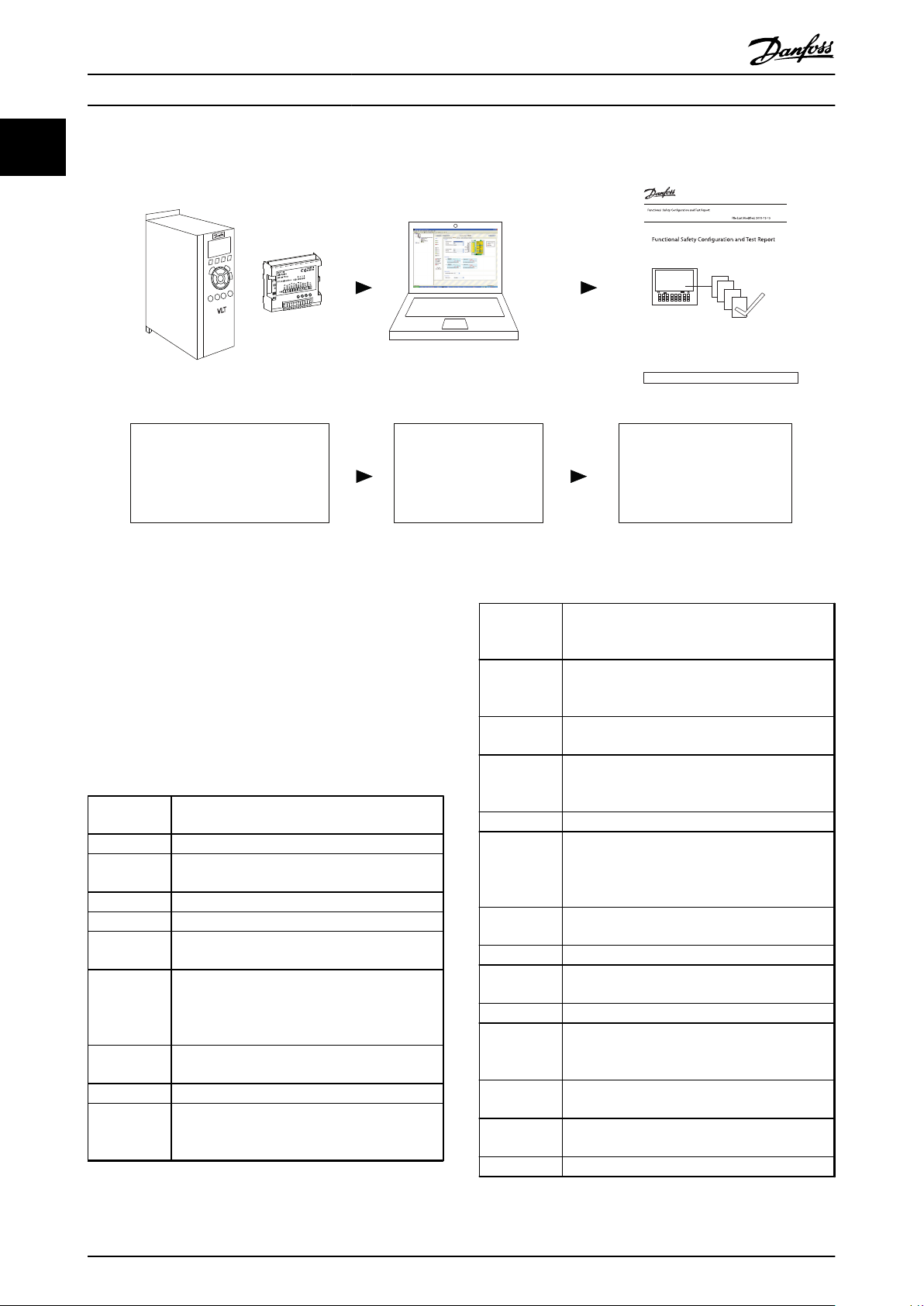
130BC961.11
+ MCT 10 + Safe Plug-in Commis sioning Report
Install
Use Manual for FC
Use Manual for MCB 150/151
Paramete rize
Use Manual for
MCT 10 Safe
Plug-in
Test
Use Commissioning
Report ge nerated via
MCT 10 Safe Plug-in
Report
Rev.Sequence: A, 3
MCT 10
Commisioning report
3 February 2012
Property of Danfoss A/S. Not to be handed over to, copied, or used by third party. Two - or three - dimensional
reproduction of contents to be authorized by Danfoss A/S.
302
FC 302 MCB 15x
1
Introduction Operating Instructions
Illustration 1.1 System Overview
Referenced literature
Error Discrepancy between a computed, observed or
measured value or condition and the specified or
VLT® AutomationDrive FC 301/FC 302 Operating
•
Instructions
MCT 10 Set-up Software Operating Instruction
•
Also refer to www.danfoss.com/drives for additional
information.
1.3 Abbreviations and Definitions
Blank Initial
State
Cat. Category (EN ISO 13849-1)
Factory settings
Error class Classification of errors into groups. The different
Factory
setting
Fatal error In the case of fatal error, the product is no
Fault Fault is a state that can be caused by an error
Fault reset A function used to restore the frequency
CCF Common Cause Failure (IEC 61508, IEC 62061, EN
61511-1, EN ISO 13849-1)
CCW Counter Clockwise
CW Clockwise
DC Diagnostic Coverage (EN ISO 13849-1, IEC
62061(IEC 61508-2))
Degree of
protection
The degree of protection is a standardized
specification for electrical equipment that
describes the protection against the ingress of
foreign objects and water (for example: IP20).
MTTF/MTTFd Mean time to failure/Mean time to dangerous
OSSD Output Signal Switching Device (EN 61496-1)
Parameter Device data and values that can be read and set
PDS(SR) Power Drive System (Safety Related)
PELV Protective Extra Low Voltage, low voltage with
DIx DI1: Digital Input 1
DI2: Digital Input 2
EMC Electromagnetic compatibility
PFD Probability of Failure on Demand (IEC 61508, IEC
Encoder Sensor for detection of the angular position of a
rotating component. Installed on/in a motor, the
PFH Probability of Failure per Hour (IEC 62061 and
encoder shows the angular position of the rotor.
theoretically correct value or condition.
error classes allow for specific responses to
errors, for example by severity.
Factory settings when the product is shipped
longer able to control the motor so that the
power stage must be immediately disabled.
converter to an operational state after a detected
error is cleared by removing the cause of the
error so that the error is no longer active.
failure (EN ISO 13849-1)
(to a certain extent) by the user
isolation. For more information: IEC 60364-4-41
or IEC 60204-1.
62061)
IEC61508)
PLC Programmable logic controller
6 Danfoss A/S © Rev. 2014-02-11 All rights reserved. MG34W302
Page 9
Introduction Operating Instructions
PL/
Performance
Level
PUST Power Up Self Test. Internal self test on the
RS-485 Fieldbus interface as per EIA-422/485 Bus
Safe state If a safe state fault is detected, the safety option
SF Safe Function
SIL Safety Integrity level (IEC61508, IEC61800-5-2,
SLS - Safely
limited speed
SO Safety Option
SRECS Safety Related Electrical Control System (IEC
SRP/CS Safety related parts of control systems (EN ISO
SS1 - Safe
Stop 1
STO - Safe
Torque Off
TM Mission Time (EN ISO 13849-1)
Warning If the term is used outside the context of safety
Discrete level used to specify the ability of
safety-related parts of control systems to perform
a safety function under foreseeable conditions
(EN ISO 13849-1)
safety option.
Description, which enables serial data
transmission with multiple devices.
goes into safe state. This includes faults related
to integrity of hardware or firmware.
IEC62061)
Safety function in accordance with EN IEC
61800-5-2, monitors the frequency converter to
check that it stays within a defined speed limit.
SLS is the abbreviation for safely limited speed.
62061)
13849-1)
Safety function in accordance with EN IEC
61800-5-2, ensures that the motor decelerates in
the expected way. SS1 is the abbreviation for
safe stop 1.
Safety function in accordance with EN IEC
61800-5-2, prevents torque from being
generated by the motor. This function is
integrated within the frequency converter as
standard. STO is the abbreviation for safe torque
off.
instructions, a warning alerts to a potential
problem that was detected by a monitoring
function. A warning is not an error and does not
cause a transition of the operating state.
1
1
Table 1.1 Abbreviations and Definitions
MG34W302 Danfoss A/S © Rev. 2014-02-11 All rights reserved. 7
Page 10
Legal Information and Safet...
Operating Instructions
2 Legal Information and Safety
22
2.1 Legal Information
2.2
Safety
According to the Machinery Directive regulation, it is
hereby stated that the original language of these
Operating Instructions is English UK.
2.1.1 Copyright and Revisions
This publication contains information proprietary to
Danfoss and is protected by Copyright laws of Denmark,
international treaties and most other countries. All
trademarks in this publication are property of the
respective companies. Danfoss and the Danfoss logotype
are trademarks of Danfoss A/S. All rights reserved.
Although Danfoss has tested and reviewed the correctness,
completeness and documentation of this publication,
Danfoss makes no warranty or representation, neither
express or implied, with respect to this publication,
including but not limited to its quality, correctness,
completeness, performance, or fitness for a particular
purpose.
Danfoss reserves the right to revise, update and change
this publication at any time without prior notice or specific
obligation to inform former or present users of such
revisions or changes.
Warranty and Liability
2.1.2
All claims to warranty and liability are rendered invalid if
2.2.1 Safety Precautions
WARNING
HIGH VOLTAGE!
Frequency converters contain high voltage when
connected to AC mains input power. Installation, start
up, and maintenance should be performed by qualified
personnel only. Failure to perform installation, start up,
and maintenance by qualified personnel could result in
death or serious injury.
WARNING
UNINTENDED START!
When the frequency converter is connected to AC mains,
the motor may start at any time. The frequency
converter, motor, and any driven equipment must be in
operational readiness. Failure to be in operational
readiness when the frequency converter is connected to
AC mains could result in death, serious injury,
equipment, or property damage.
CAUTION
This option is suitable for performing mechanical work
on the frequency converter system or affected area of a
machine only. It does NOT provide electrical safety. This
option should NOT be used as a control for starting
and/or stopping the frequency converter. See the
requirements for those applications in ISO 12100.
the product was used contrary to the purpose for
•
which it is intended.
damage can be attributed to not having followed
•
the guidelines in the manual.
operating personnel are not suitably qualified.
•
any type of modification has been made (e.g.
•
exchanging components on the PCB boards,
soldering work etc.).
8 Danfoss A/S © Rev. 2014-02-11 All rights reserved. MG34W302
2.2.2 Risk Assessment
CAUTION
The safety option is intended to be part of the safetyrelated control system of a machine. Before installation,
a risk assessment shall be performed to determine
whether the specifications of this safety option are
suitable for all foreseeable operational and environmental characteristics for the system in which it will be
installed.
The system user is responsible for
the set-up, safety rating and validation of any
•
sensors or actuators connected to the system.
completing a system-level risk assessment and
•
reassessing the system any time a change is
made.
Page 11
Legal Information and Safet...
Operating Instructions
providing supposition (as needed for the
•
application) that the system fulfills desired safety
rating.
project management and proof testing.
•
programming the application software and the
•
safety option configurations in accordance with
the information in this manual.
access to the control system.
•
analysing all configuration settings and selecting
•
the proper setting to achieve the required safety
rating.
Safety Regulations
2.2.3
Check that the mains supply has been discon-
•
nected and that the necessary time has elapsed
before removing motor and mains supply plugs
and before commencing any repair work.
The [Off] key on the LCP does not disconnect
•
mains supply and must never be used as a safety
switch.
Ensure the following in accordance with national
•
and local regulations:
The equipment must be properly
-
earthed
The user must be protected against
-
supply voltage
The motor must be protected against
-
overload
The earth leakage current exceeds 3.5 mA.
•
Protection against motor overload is not included
•
in the factory setting. If this function is desired,
set 1-90 Motor Thermal Protection to data value [4]
ETR trip 1 or data value [3] ETR warning 1.
Do not remove the plugs for the motor and
•
mains supply while the frequency converter is
connected to mains.
NOTICE
The frequency converter has more voltage sources than
L1, L2 and L3, when load sharing (linking of DC
intermediate circuit) or external 24 V DC are installed.
engineers and are suitably experienced to
operate devices, systems, plant and machinery in
accordance with the general standards and
guidelines for safety technology.
are familiar with the basic regulations concerning
•
health and safety/accident prevention
have read and understood the safety guidelines
•
given in this description and also the instructions
given in the VLT® AutomationDrive FC 301/FC 302
Operating Instructions.
have a good knowledge of the generic and
•
specialist standards applicable to the specific
application.
Users of PDS(SR)s are responsible for
hazard and risk analysis of the application.
•
identifying safety functions required and
•
allocating SIL or PLr to each of the functions.
other subsystems and the validity of signals and
•
commands from them.
designing appropriate safety-related control
•
systems (hardware, software, parameterisation,
etc.).
The following symbols are used in this document:
WARNING
Indicates a potentially hazardous situation which could
result in death or serious injury.
CAUTION
Indicates a potentially hazardous situation which could
result in minor or moderate injury. It may also be used
to alert against unsafe practices.
NOTICE
Indicates important information, including situations that
may result in damage to equipment or property.
Approvals
2 2
2.2.4 Qualified Personnel
The products may only be assembled, installed,
programmed, commissioned, maintained and decommissioned by persons with proven skills. Persons with proven
skills
are qualified electrical engineers, or persons who
•
have received training from qualified electrical
MG34W302 Danfoss A/S © Rev. 2014-02-11 All rights reserved. 9
Page 12
130BC308.10
Field bus
Interface
MCB 150/151
Safety Option
Option A
Option B
Inte rnal Bus 1
Inte rnal Bus 2
μ C
Control Card
IGBT
STO
37
E
M
PLC
E
M
E
R
E
N
C
Y
G
S
T
O
P
Functions and System Overvi...
Operating Instructions
3 Functions and System Overview
3.1 System Overview
with hard guarding, access doors, and safety gates with
solenoid-lock or -unlock safety switches. When the speed
33
of the monitored device drops below the set switch point
(where its speed is no longer considered dangerous), the
safety option sets S37 output low. This allows the operator
to open the safety gate. In speed monitor applications, the
safety output S37 is high for operation (when the motor
speed of the monitored device is below the set switch
point). When the speed exceeds the set value, indicating a
too-high (dangerous) speed, the safety output is low.
The frequency converter
removes the power to the motor,
•
switches the motor to torque-free, if Safe Torque
•
Off is activated
The safety control system
activates the safety functions via inputs on the
•
safety option
evaluates signals from safety devices, such as
•
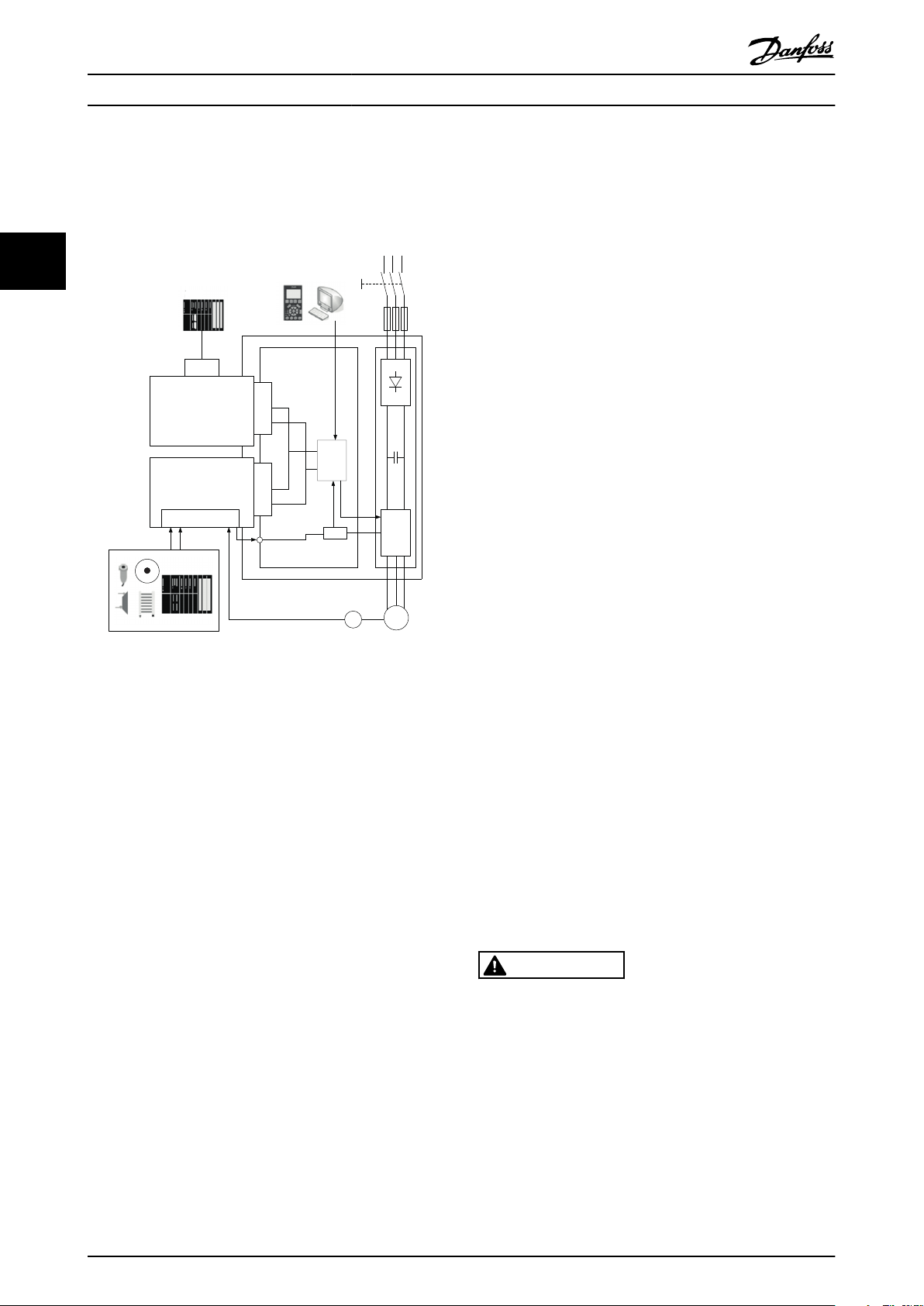
Illustration 3.1 FC 302 with Safety Option and Fieldbus Option
The safty option performs safety functions in accordance
with EN IEC 61800-5-2. It monitors safe motion sequences
on frequency converters, which are safely brought to a
stop and shut down in the event of an error.
The safety option
activates safety functions
•
monitors safe motion sequences
•
signals the status of safety functions to the safety
•
control system via possible connected Profibus
fieldbus
activates the selected failure reaction Safe Torque
•
Off or Safe Stop 1, in the event of an error
There are 2 variants of the safety option, one with HTL
encoder interface (MCB 151) and one with TTL encoder
interface (MCB 150).
The safety option is constructed as a standard option for
the VLT® AutomationDrive FC 302 and is automatically
detected after mounting.
The safety option can be used to monitor the stopping,
starting or speed of a rotating or laterally moving device.
As speed monitor, the option is often used in combination
10 Danfoss A/S © Rev. 2014-02-11 All rights reserved. MG34W302
3.1.1
RISK OF HAZARD!
If external forces act on the motor (vertical axis) and an
unwanted movement, for example caused by gravity,
could cause a hazard, add measures for fall protection
before operating the motor.
Triggering the Safe Torque Off safety function means that
the delay time for motors with holding brake is not
effective. The motor cannot generate holding torque to
bridge the time to application of the holding brake. Check
whether additional measures have to be taken; for
example, this may cause the load of vertical axes to lower.
processes the safety option status function
•
provides safe connection between safety option
•
and safety control system
provides fault detection at activation of safety
•
functions (shorts across contacts, short circuit) on
signal between the safety control system and
safety option
Behaviour of Holding Brake
CAUTION
E-STOP push buttons
-
Non Contact Magnetic switch
-
Interlocking switch
-
Light curtain devices
-
Page 13
130BC962.10
Detect
Sensor
E.g. lightcurtain
Process Switch
Logic
E.g. MCB 15x
Actuator
E.g. FC 302
Functions and System Overvi... Operating Instructions
3.1.2 Safety Certification
The safety option is certified for use in safety applications up to and including SIL 2 according to EN IEC 61508 and EN IEC
62061, Performance Level PL d and Category 3 according to EN ISO 13849-1. Safety requirements are based on the
standards valid at the time of certification. The IFA (Institute for Occupational Safety & Health) has approved the safety
option for use in safety-related applications where the de-energised state is considered to be the safe state. All of the
examples related to I/O included in this manual are based on achieving de-energisation as the safe state.
3.1.3 Implementation in Control Systems
In many cases design measures are not sufficient and protective devices are needed to minimise risk. In this context, safety
functions executed by SRP/CS (safety related parts of control systems) are defined. SRP/CS includes the entire safety chain
with sensor (detect), logic (process) and actuator (switch).
Safety functions are defined on the basis of both the application and the hazard. They are often specified in a Type C
standard (a product standard) which provides precise specifications for special machines. If a C standard is not available, the
machine designer defines the safety functions. Typical safety functions are described in more detail in EN ISO 13849-1,
section 5, Specification of Safety Functions. The safety functions for frequency converter systems are described in IEC
61800-5-2.
3 3
Illustration 3.2 Sensor-Logic-Actuator Safety Chain
3.2 Functions
3.2.1 Specification of Safety Functions
The standards require a specification of functional
requirements. The specification must contain details about
each safety function that should be executed. Also define
the
necessary interfaces with other control functions
•
required error responses
•
performance level required PLr or achievable SIL
•
level
3.2.1.1
Performance Level (PL) and Safety
Integrity Level (SIL)
For safety-related control systems, Performance Level (PL),
according to EN ISO 13849-1, and SIL levels, according to
EN IEC 61508 and EN IEC 62061, include a rating of the
system's ability to perform its safety functions.
All of the safety-related components of the control system
must be included in both a risk assessment and the
determination of the achieved levels. Refer to EN ISO
13849-1, EN IEC 61508 or EN IEC 62061 standards for
complete information on requirements for PL and SIL
determination.
3.2.2 Validation of Performance Level
Check whether the required Performance Level “PLr”,
determined in the risk assessment, is achieved by the
selected system for each safety function used.
Check the calculation using the SISTEMA SW Tool of IFA
(Institute for Occupational Safety & Health). Danfoss
provides a component library which can be used for the
calculation. Danfoss offers corresponding services to
support the system check by calculation. Library can be
downloaded from www.dguv.de/ifa/en/pra/softwa/sistema.
If using another validation method for the performance
level, use the characteristic safety values specified.
MG34W302 Danfoss A/S © Rev. 2014-02-11 All rights reserved. 11
Page 14
130BC373.11
time
frequency
time
frequency
A
B
C
Functions and System Overvi...
Operating Instructions
3.2.3 Activation of Safety Functions
The safety functions are activated using the dual-
•
pole safe inputs on the safety option.
These inputs operate in accordance with the fail-
•
33
safe principle (on switching off). The safety
control system activates the safety functions via a
1/0 transition.
Deactivate the safety functions before applying
•
any changes to them.
3.2.4 Simultaneous Activation of Safety
Functions
All safety functions can be active at the same time.
However, Safe Torque Off has priority over all other safety
functions. Functions already started (e.g. Safe Stop 1 or
Safely Limited Speed) are canceled and the frequency
converter coasts.
Safe Torque Off has the highest priority. If the
•
Safe Torque Off function is triggered, a Safe
Torque Off is managed no matter what other
If 2 Safe Stop 1 functions are active at the same time, the
function with the steepest ramp has higher priority than
the function with less steep ramp.
If 2 Safely Limited Speed functions are active at the same
time, the function with the lowest speed limit has higher
priority than the function with higher speed limit.
If 2 equal safety functions have to be configured, they
must be parameterised as SS1-a and SS1-b or SLS-a and
SLS-b.
functions are active.
Safe Stop 1 has medium priority to the other safe
•
functions.
Safely Limited Speed has the lowest priority.
•
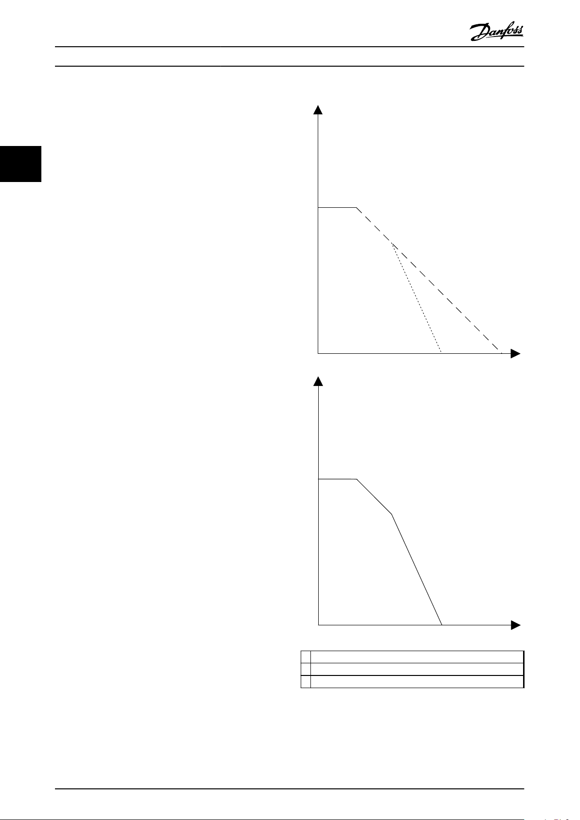
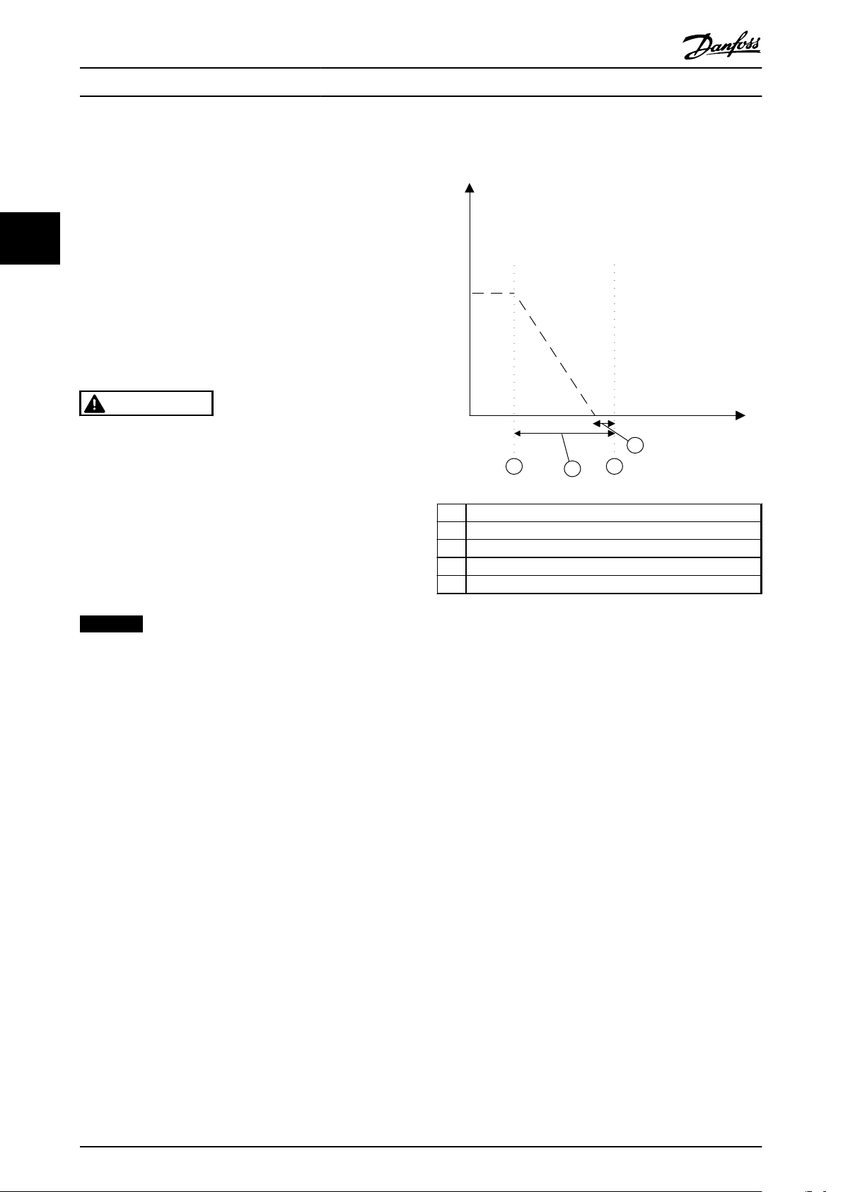
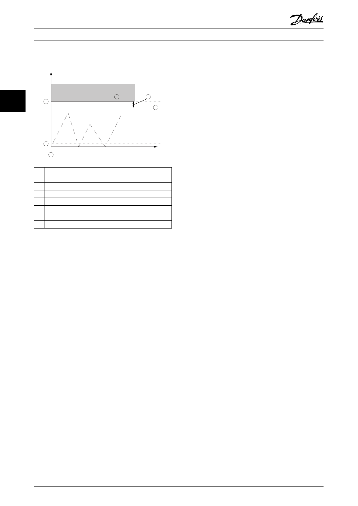
Ramp stop function 1
A
12 Danfoss A/S © Rev. 2014-02-11 All rights reserved. MG34W302
B Ramp stop function 2
C Actual ramp stop function
Illustration 3.3 2 Safe Stop 1 Safety Functions Active
Illustration 3.3 shows the result of activating first a Safe
Stop 1 function with a given ramp and afterwards
Page 15

Functions and System Overvi...
Operating Instructions
activating a second Safe Stop 1 function with a steeper
ramp. The lower graph shows the actual ramp function.
3.2.5 Functional Proof Tests
The functional safety standards require that functional
proof tests are performed on the equipment used in the
system. Proof tests are performed at user-defined intervals
and are dependent on PFD and PFH values.
3.2.6 PFD and PFH Definitions
Safety-related systems can be classified as operating in
either a Low Demand mode, or in a High Demand/
Continuous mode.
Low demand mode
The frequency of demands for operation made on a safetyrelated system is no greater than once per year.
High Demand/Continuous mode
The frequency of demands for operation made on a safetyrelated system is greater than once per year.
The SIL value for a low demand safety-related system is
directly related to order-of-magnitude ranges of its average
probability of failure on demand (PFD). The SIL value for a
High Demand/continuous mode safety-related system is
directly related to the probability of a dangerous failure
per hour (PFH).
Intended Use of the Safety Option
3.2.7
CAUTION
RISK OF PERSONAL INJURY AND EQUIPMENT
DAMAGE!
To avoid personal injury and equipment damage, only
use the safety option for its intended purpose.
The following is considered as improper use
any component, technical or electrical modifi-
•
cation to the frequency converter
use of the frequency converter outside the
•
allowed electrical and environmental conditions
specified in chapter 9 Technical Specifications
and in the VLT® AutomationDrive FC 301/FC 302
Operating Instructions.
The safety option is designed for use in safety-related
applications. It meets the requirements for safety functions
in accordance with IEC 61800-5-2, regarding safe motion
monitoring.
3.2.8
MCT 10 Set-up Software with Safe
Plug-in
Use MCT 10 Set-up Software to configure the safety
functions supported in safety option.
Configuration of the safety functions is required
•
for safe motion sequences. In the event of an
error or fault, these functions shut down the
frequency converter's power element in a safe
and controlled way.
Setting of limit values, braking ramps for the
•
safety functions, monitoring of motion sequences.
The software
runs in full with a license key. All functions are
•
available from MCT 10 Set-up Software version
3.18.
supports the configuration of applications with
•
up to max. 256 safety options per project
has a simple language setting for the user
•
interface.
A PDF file and a commissioning report can be generated
for documentation of the project and all its settings.
3.3
Unit Features
The safety option has the following features
2 Dual-pole, digital inputs to activate the safety
•
functions in accordance with EN IEC 61800-5-2
Safe Torque Off (STO)
-
Safe Stop 1 (SS1)
-
Safely Limited Speed (SLS)
-
Reset function
•
Digital input 2 can be used for resetting
-
the safety option after an error or after
deactivation of a safety function.
Status indicators
•
Safe input status (LED 1 and LED 2)
-
Safe output status (LED 4)
-
LED 3 reserved for future use (always in
-
off state)
By Fault or warning the LEDs indicate a
-
failure via flash pattern, see Table 8.2
Supply voltage
•
Internally supplied by the frequency
-
converter.
24 V DC output for safety sensors and
-
encoder available.
3 3
MG34W302 Danfoss A/S © Rev. 2014-02-11 All rights reserved. 13
Page 16
E30BC325.11
MCB 150
Safe Option
SW. ver. xx. xx
Option B
130B3280
LED:
123 4
TTL Enc. interface
Y30/
DI1 A
GND
DI1 B
ENC A
DI2 A
ENC nA
ENC B
DI2 B
ENC nB
24V
GND
S37
1 2 3 4 5 6 7 8 9 10 11 12
E30BC326.11
MCB 151
Safe Option
SW. ver. xx. xx
Option B
130B3290
LED:
1
2
3 4
HTL Enc. interface
Y31/
DI1 A
GND
DI1 B
ENC A
DI2 A
ENC B
DI2 B
24V
GND
S37
1 2 3 4 5 6 7 8 9 10 11 12
GND
GND
Functions and System Overvi...
Operating Instructions
3.4 Front View
Refer to EN IEC 61800-5-2:2007 (4.2.2.2) for a definition of
Safe Torque Off (STO).
A Category 1 stop triggers a controlled stop. The safety
option monitors the controlled stop. If a power outage or
an error occurs, a controlled stop is impossible. Trigger the
33
safety function Safe Torque Off after the stop to shut off
the motor torque.
Refer to EN IEC 61800-5-2:2007 (4.2.2.3) for a definition of
Safe Stop 1 (SS1).
An evaluation of the machine-related risks determines
Illustration 3.4 MCB 150
which of the 2 stopping methods to use.
NOTICE
When designing the machine application, consider
timing and distance for a coast to stop (Stop Category 0
or Safe Torque Off). For more information regarding stop
categories, refer to EN IEC 60204-1.
3.5.1 Operation and Requirements
3.5 Categories of Safe Stop
International standard EN/ISO 13850 specifies the
functional requirements and design principles of
emergency stop devices.
It applies to all machines, whatever type of energy is used
to control this function.
The standard allows 2 types of stop
During a category 0 stop, the motor coasts down in an
uncontrolled way. If access to the machine coasting down
involves a hazard (results of the hazard and risk analysis),
take protective measures to avoid the hazard.
Illustration 3.5 MCB 151
Category 0 stop: Stopping by immediately
•
cutting-off power or mechanical disconnection
between the dangerous components
Category 1 stop: Controlled stopping with power
•
maintained to the actuator to achieve stopping
(braking for example), then cut-off of power
when zero speed is reached.
The safety option is redundant and self-checking. It
requires digital input signals from an input sensor (e.g.,
PNP proximity switch) or higher resolution TTL or HTL
encoders to monitor for either safe stop or speed
conditions.
Safety Functions
3.5.2
Safety functions maintain a safe condition or prevent
hazardous conditions from arising. The safety functions for
frequency converters are defined in EN IEC 61800-5-2.
The safety option implements the following safety
functions
Safe Torque Off (STO)
•
No power is being fed to the motor
-
which can generate a rotation. Stop
category 0 to EN IEC 60204-1
Safe stop 1 (SS1)
•
Motor decelerates. Monitoring of
-
deceleration ramp and Safe Torque Off
following zero speed, or Safe Torque Off
at the end of a deceleration time. Stop
category 1 to EN IEC 60204-1
Safely limited speed (SLS)
•
Prevents exceeding a defined speed
-
value
14 Danfoss A/S © Rev. 2014-02-11 All rights reserved. MG34W302
Page 17

frequency
130BC318.10
time
1
2
A
Functions and System Overvi...
Operating Instructions
3.5.3 Safe Torque Off - STO
The safety function Safe Torque Off disconnects power to
the motor. It is implemented via the frequency converter's
shutdown path and the safety option’s safe outputs.
Features of the safety function
The motor becomes torque-free and no longer
•
generates any hazardous movements
To prevent the frequency converter from running
•
down in an uncontrolled manner. In normal
operation, activate the safety function Safe
Torque Off via the safety function Safe Stop 1
Safe Torque Off is only activated directly when
•
There is an internal error on the safety
-
option
The Safe Stop 1 delay time is set to 0
-
One of the inputs DI1 or DI2 has been
-
selected as Safe Torque Off function
The safety function Safe Torque Off corresponds
•
to a category 0 stop (uncontrolled stop) in
accordance with EN IEC 60204-1.
Prerequisites for normal operation
Input DI1 or DI2: "1" Signal (+24 V DC)
•
S37 output: "1" Signal (+24 V DC).
•
Safety function is activated
By an error after limit values have been exceeded
•
for Safe Stop 1 and Safely Limited Speed
By an internal error on the safety option or
•
frequency converter, if the frequency converter
can no longer be controlled
By executing the safety function Safe Stop 1 (1/0
•
transition). In this case the frequency converter is
monitored before it is switched to torque-free.
By download of parameterisation via MCT 10 Safe
•
Plug-in if the current frequency converter is
running.
By executing the safety function Safe Torque Off
•
(1/0 transition). This function ensures that no
torque-generating energy can continue to affect a
motor and prevents unintentional start-ups.
WARNING
If any external forces influence the motor axis (e.g.
suspended loads), additional measures (e.g. a safety
holding brake) are required to eliminate hazards.
The Safe Torque Off (STO) may be used where power
removal is required to prevent an unintended start. The
function disables the control voltage of the frequency
converter output stage. Thus, it prevents the frequency
converter from generating the voltage required to rotate
the motor (see Illustration 3.6). The function allows for
performing maintenance work on non-electrical parts of
the machinery without switching off the power supply to
the frequency converter.
A Actual frequency
1 Activation of Safe Torque Off
2 Motor standstill
Illustration 3.6 Safe Torque Off
Safe Stop 1 - SS1
3.5.4
The safety function Safe Stop 1 monitors the deceleration
to zero speed in a controlled manner and activates Safe
Torque Off after detection of stop. The Safe Stop 1 can
either be configured as SS1 Delay or SS1 Ramp.
Features of the safety function
The safety function Safe Stop 1 corresponds to a
•
category 1 stop (controlled braking) in
accordance with EN IEC 60204-1
Monitoring the speed deceleration after which
•
the energy supply to the motor is safely
interrupted
The motor becomes torque-free and removes
•
hazardous movements
3.5.4.1
Select SS1 Delay to activate Safe Stop 1 function while a
parameterised safety delay timer expires.
SS1 Delay
3 3
MG34W302 Danfoss A/S © Rev. 2014-02-11 All rights reserved. 15
Page 18
130BC321.10
1 2
time
frequency
3
4
A
Functions and System Overvi...
Safe Torque Off is activated immediately when the
configured Stop Delay has expired, regardless of speed,
see chapter 6.1 Configuration for parameter settings.
Selecting the SS1 settings
1.
Enter 42-41 Ramp Profile
33
2. Select
2a
[0] Linear, if the ramp must follow a
linear curve
2b
[2] S-ramp Const Time, if the ramp
should follow an S-ramp
By using SS1 Delay, the frequency converter attempts to
follow the selected ramp. After a specified delay time, Safe
Torque Off is activated and the motor is made torque free.
Operating Instructions
CAUTION
Using SS1 Delay may result in the motor still spinning
when the Safe Torque Off is activated. The risk analysis
for the machine must indicate that this behaviour can be
tolerated. An interlock may be required.
Default value in 42-40 Type is [0] Delay. If this value is
selected, the Safe Stop 1 function activates a braking ramp
defined from a selected time delay in 42-42 Delay Time.
This means that the braking ramp is linear. Select the value
of 42-43 Delta T (the % of the delay time), which is a
reasonable tolerance after the SS1 Delay Time has expired.
NOTICE
The SS1 delayu function does not monitor the stopping
of the frequency converter!
The safety relevant time, Delta T, allows the frequency
converter to come to a stop before Safe Torque Off is
activated. Thus ensuring that the system is also stopped
before Safe Torque Off is activated. If a fault occurs, the
frequency converter does not come to a stop. It coasts
after the time delay no matter of the speed of the
frequency converter.
A Actual frequency
1 Activation of SS1 Delay Timer
2 Activation of Safe Torque Off
3 42-42 Delay Time
4 42-43 Delta T
Illustration 3.7 SS1 Delay
When Safe Stop 1 function is active, the frequency
converter brings the motor to zero speed. The Safe Torque
Off function is triggered after a specified safety-relevant
time. This safety function corresponds to a controlled stop
of the frequency converter according to EN IEC 60204-1,
stop category 1.
3.5.4.2
An S-ramp gives non-linear deceleration, compensating for
jerks in the application.
SS1 Delay with S-ramp Stop Profile
1. Define a speed profile by a delay (a ”worst case”
delay from actual frequency to zero speed) and a
delay tolerance. The safety relevant time, Delta T,
allows the frequency converter to come to a stop
before Safe Torque Off is activated. Thus ensuring
that the system is also stopped before Safe
Torque Off is activated. If a fault occurs, the
frequency converter does not come to a stop. It
coasts after the time delay regardless of the
frequency converter speed.
2. Define an S-ramp configuration, which achieves
zero speed within the delay.
16 Danfoss A/S © Rev. 2014-02-11 All rights reserved. MG34W302
Page 19

130BC322.11
1
2
time
frequency
3
4
actual
frequency
5
6
Functions and System Overvi...
Operating Instructions
3. Configure the S-Ramp ratio at deceleration start
in 42-48 S-ramp Ratio at Decel. Start and set
42-49 S-ramp Ratio at Decel. End for S-Ramp ratio
at deacceleration end.
Parameter Unit Range Default
42-42 Delay Time s 0.1-3600.0 s 1.0 s
42-43 Delta T % 0-50% 5%
42-48 S-ramp Ratio at Decel. Start % 1-99 50
42-49 S-ramp Ratio at Decel. End % 1-99 50
Table 3.1 Parameters for SS1 Delay with S-ramp Stop Profile
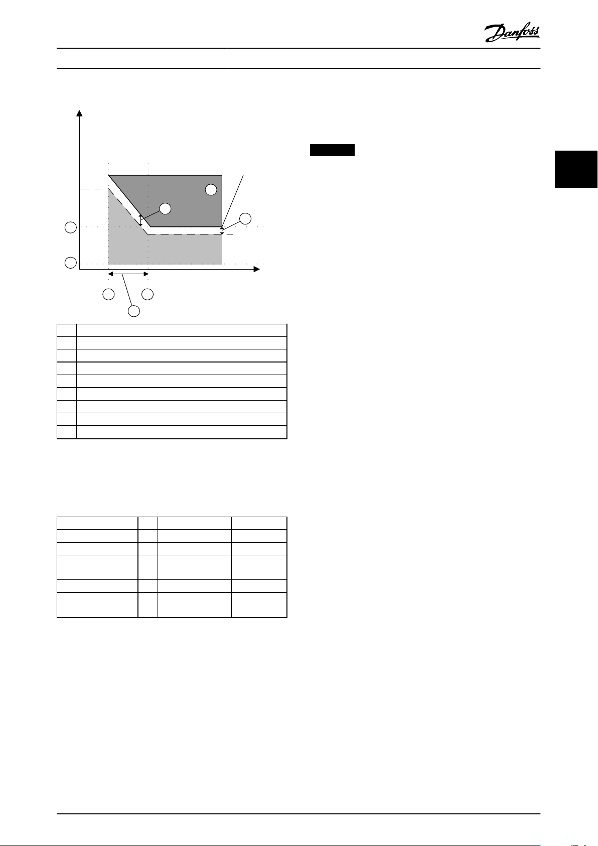
A Actual frequency
1 Activation of SS1 Ramp Delay
2 Activation of Safe Torque Off
3 42-42 Delay Time
4 42-43 Delta T
5 42-48 S-ramp Ratio at Decel. Start
6 42-49 S-ramp Ratio at Decel. End
Illustration 3.8 SS1 Delay with S-ramp Stop Profile
3.5.4.3
SS1 Ramp
NOTICE
The SS1 Ramp function can only be used when an
encoder is connected to the safety option.
This Safe Stop type allows access to the hazard area
immediately after motion is detected as stopped rather
than waiting until a specific time has elapsed.
The safety option monitors the following functions
Braking ramp
•
In the MCT 10 Set-up Software Safe
-
Plug-in, the braking ramp is specified
and monitoring is activated. The braking
period depends on the speed of the
motor when braking is started. The
braking ramp can be monitored via a
maximum speed error specified in the
MCT 10 Set-up Software tolerable in
42-45 Delta V.
Braking ramp in normal operation
•
The frequency converter starts with the
-
configured braking ramp when safety
function Safe Stop 1 has been activated.
Once the speed is at zero speed limit,
Safe Torque Off is activated.
Safety function Safe Torque Off is activated when
•
the configured limit value for the position error is
exceeded
A standstill threshold Zero speed (42-46 Zero Speed) for
activating the safety function Safe Torque Off can be
specified in MCT 10 Set-up Software.
Safety function Safe Torque Off is activated when zero
speed is achieved.
Prerequisites for normal operation
Input DI1 or DI2: "1" Signal (+24 V DC)
•
S37 output: "1" Signal (+24 V DC). The safety
•
option is ready for operation
A 1/0 transition at the selected DI1 or DI2 input activates
the safety function.
Signal status of the inputs DI1 and DI2
The Safe Stop 1 ramp starts when one of the 2 inputs is
set to “0”. The safety function Safe Torque Off is activated
once the braking ramp has reached zero speed.
3.5.4.4
For the stopping process, the safety option initiates a stop
signal to the frequency converter and monitors the
controlled braking by monitoring the braking ramp. The
admissible deceleration ramp is specified in
42-44 Deceleration Rate. The frequency converter must
decelerate at least with the steepness of this deceleration
ramp in the event of a Safe Stop 1 request from the safety
option, even under heavy load. If the frequency converter
does not fulfill the admissible deceleration ramp during a
Safe Stop 1 requested by the safety option, a Safe Torque
Off is triggered immediately. The motor then performs an
uncontrolled stop. This action prevents the frequency
converter from continuing to run or even accelerating in
the event of an error.
SS1 Ramp Slope
3 3
MG34W302 Danfoss A/S © Rev. 2014-02-11 All rights reserved. 17
Page 20
130BC319.10
6
4
3
7
1 2
5
time
frequency
6
A
B
130BC320.10
6
4
7
1 2
5
time
frequency
6
3
A
B
Functions and System Overvi...
Operating Instructions
Parameter Unit Range Default
42-44 Deceleration Rate RPM/s 1-30000 RPM/s 1500 RPM/s
42-45 Delta V RPM 1-10000 RPM 120 RPM
42-46 Zero Speed RPM 1-600 RPM 10 RPM
Table 3.2 Parameters for SS1 Ramp Slope
Parameter Unit Range Default
42-47 Ramp Time s 0.1 - 3600.0 s 1.0 s
42-45 Delta V RPM 1 - 10000 RPM 120 RPM
42-46 Zero Speed RPM 1 - 600 RPM 10 RPM
Table 3.3 Parameters for SS1 Ramp Time
33
A Actual frequency
B SS1 Ramp
1 Activation of SS1 Ramp Slope
2 Activation of STO
3 42-44 Deceleration Rate
4 42-45 Delta V
5 42-46 Zero Speed
6 Safety function monitors
7 Activation of failure function
Illustration 3.9 SS1 Ramp Slope
A Actual frequency
B SS1 ramp
1 Activation of SS1 Ramp Time
2 Activation of STO
3 42-47 Ramp Time
4 42-45 Delta V
5 42-46 Zero Speed
6 Safety function monitors
7 Activation of failure function Safe Torque Off
Illustration 3.10 SS1 Ramp Time
When the Safe Stop 1 function is active, the frequency
converter brings the motor to zero speed. The deceleration
is monitored. If the monitored deceleration is slower than
expected or at zero speed, Safe Torque Off is triggered.
This safety function corresponds to a controlled stop of the
frequency converter according to EN IEC 60204-1, stop
category.
3.5.4.5
Define a speed monitoring profile by a deceleration time
and a tolerable speed (Delta V).
18 Danfoss A/S © Rev. 2014-02-11 All rights reserved. MG34W302
SS1 Ramp Time
Safely Limited Speed (SLS)
3.5.5
NOTICE
The Safely Limited Speed function can only be used
when an encoder is connected to the safety option.
This function is used to limit a machine speed. The main
goal is to monitor the motor speed and to adjust the
speed to a set point. There are 2 types of Safely Limited
Speed
SLS without ramp: Monitors the motor speed and,
•
depending on the setting of 42-52 Fail Safe
Page 21
time
1
2
4
5
3
6
frequency
130BC324.10
A
B
Functions and System Overvi... Operating Instructions
Reaction, trips in Safe Torque Off or Safe Stop 1 if
an overspeed occurs
SLS with ramp: Limits the motor speed to a set
•
point and, depending on the setting of 42-52 Fail
Safe Reaction, trips in Safe Torque Off or Safe
Stop 1, if an overspeed occurs
The Safe Limited Speed is given as speed limit in
42-51 Speed Limit. The value for the cut-off speed partly
depends on the motor that is being used. A suggested
value from MCT 10 Set-up Software calculates a value for
which Danfoss guarantees functionality. This value is called
delta speed limit and is added to the selected speed limit
and suggested as value in 42-50 Cut Off Speed.
3 3
3.5.5.1
SLS without Ramp
The safety function Safely Limited Speed monitors whether
a specified velocity value is exceeded since it was activated
via DI1 or DI2. The function is active until the selected
input has been put to high again.
If 2 Safe Speed limits must be monitored, set one of the 2
Safe Digital Inputs DI1 or DI2 in 42-20 Safe Function to SLSa or SLS-b. Then select the input type under 42-21 Type.
The cut-off speed represents the maximum allowed
frequency of the actual motor frequency. If the motor
frequency accelerates above that value, the safety option
enters external fault selected (STO or SS1 Ramp), and the
error is given. The frequency value at which a shutdown is
realised should be parameterised in 42-50 Cut Off Speed.
Parameter Unit Range Default
42-50 Cut Off Speed RPM 120-10000 RPM 270 RPM
42-51 Speed Limit RPM 1-9999 RPM 150 RPM
42-52 Fail Safe
Reaction
Table 3.4 Parameters for SLS without Ramp
n/a Safe Torque Off/Safe
Stop 1
Safe Torque
Off
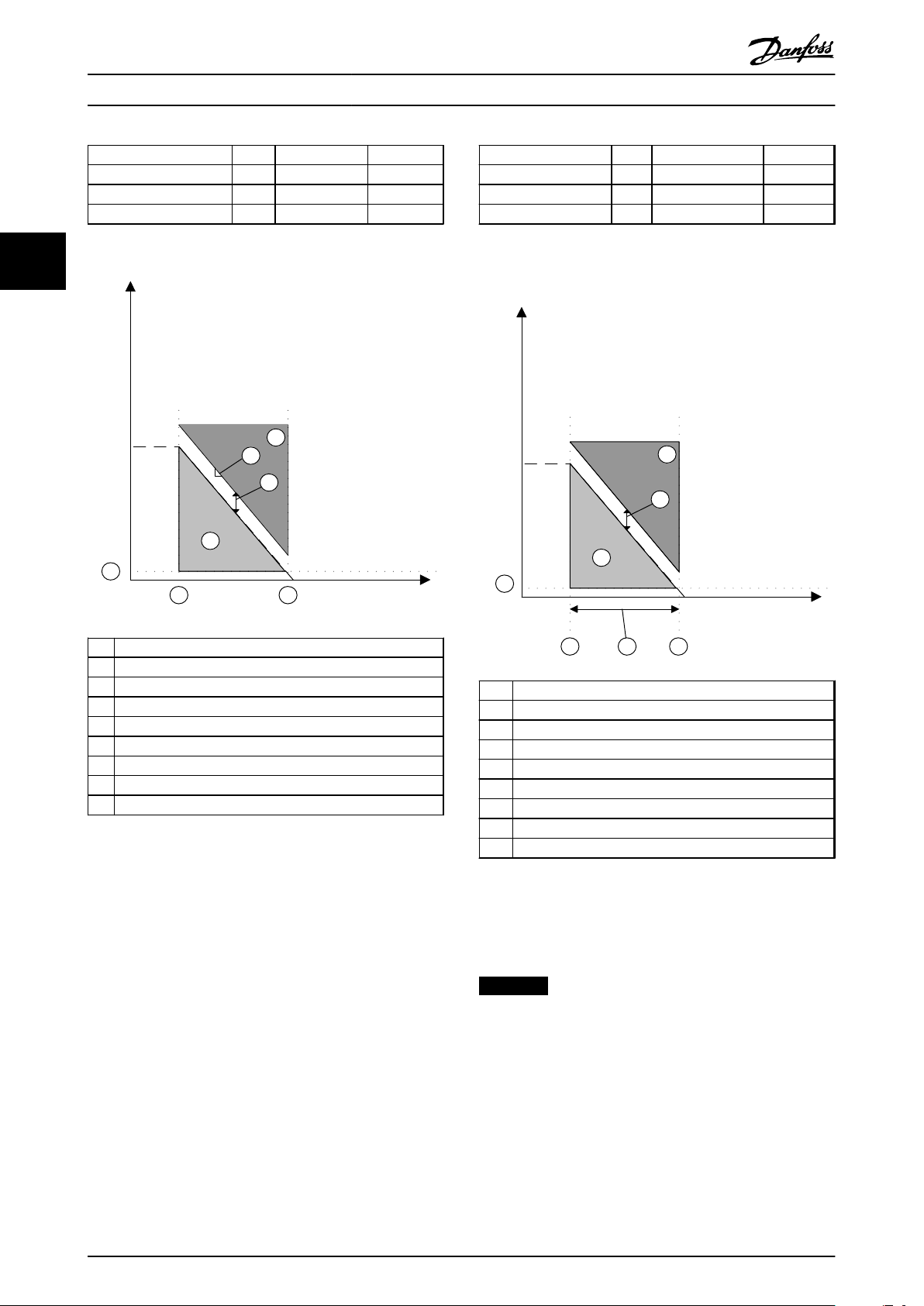
Actual frequency
A
B SLS limit
1 SLS is activated
2 42-51 Speed Limit
3 42-50 Cut Off Speed
4 Delta speed limit
5
Activation of failure function set in 42-52 Fail Safe Reaction
6
Fixed value of 120 RPM in 42-19 Zero Speed Limit
Illustration 3.11 SLS without Ramp
If speed exceeds the limit, 42-52 Fail Safe Reaction is
activated. The safety function can either be Safe Torque
Off or SS1 Ramp Time. Safe Stop 1 can only be triggered
as error response if one Safe Stop 1 function has been set
as Safe Stop 1 with ramp time function, set in 42-40 Type.
MG34W302 Danfoss A/S © Rev. 2014-02-11 All rights reserved. 19
Page 22
130BC959.10
4
2
3
6
1
5
frequency
time
A
B
Functions and System Overvi... Operating Instructions
Safe jog in combination with SLS
Limited Speed limit, the limit comes into effect
immediately without ramping. When the Safely Limited
Speed function is deactivated, the speed limits are ramped
up back to the values defined in parameter group 3-1*
References, and the actual speed returns to the reference
value if it was limited by this function.
33
Follow these steps to configure the Safely Limited Speed
operation
1. If a safe speed limit must be monitored, set one
of the 2 safe digital inputs, DI1 or DI2, to [1] SLS-a
or [2] SLS-b in 42-20 Safe Function.
2.
Select input type in 42-21 Type.
3.
Select 42-53 Start Ramp to run Safely Limited
Speed with monitored braking ramp. The default
A Actual frequency
B SLS limit
1 SLS is activated
2 42-51 Speed Limit
3 42-50 Cut Off Speed
4 Delta speed limit
5
Activation of failure function set in 42-52 Fail Safe Reaction
6
Fixed value of 120 RPM in 42-19 Zero Speed Limit
Illustration 3.12 Safe Jog
When the safety option actively monitors Safely Limited
Speed, and the motor speed is at or below the configured
safe speed limit, the function monitors the speed until the
function is deactivated.
value is [0] No for applications without SLS Ramp
control.
4. Set the time allowed to reach Safe Limited Speed
in 42-54 Ramp Down Time.
5.
Set the value in 42-50 Cut Off Speed.
Access under specific conditions of reduced risk
Under specific conditions of reduced risk, safe jog allows
for access to areas for fault-finding, commissioning, etc. On
machines where safe jog (jogging or inching) is needed,
this is also possible from zero speed setpoint.
By activating Safely Limited Speed, the motor can be
moved at safe jog resulting in a number of cycles and with
safely monitored movements. The motor can be started
and stopped continuously also from zero speed.
3.5.5.2
SLS with Ramp
If this safety function is needed, configure the safety
option for Safely Limited Speed (SLS). When the inputs DI1
or DI2 are selected as SLS, input is OFF, feedback velocity
is monitored and compared against a configurable safe
speed limit.
Select 42-53 Start Ramp to configure an SLS Monitoring
Ramp. The ramping begins when SLS monitoring is
requested by the selected input for SLS transition from ON
to OFF. The safety option starts monitoring for safe limited
speed when the ramp-down times out. If the system speed
exceeds or is equal to the configured safe speed limit
during Safely Limited Speed monitoring, a Safely Limited
Speed fault occurs and the safety option initiates the
configured Safe Stop type selected in 42-52 Fail Safe
Reaction.
The ramping begins at the absolute value of the actual
speed. If the actual speed is already below the Safely
20 Danfoss A/S © Rev. 2014-02-11 All rights reserved. MG34W302
Page 23
130BC323.10
1 2
frequency
3
5
6
4
time
4
7
A
B
Functions and System Overvi...
Operating Instructions
Shorts between the 2 lines of a dual channel input are not
detected. Therefore the cables of the channels must be
routed separately to exclude short circuits.
NOTICE
A Actual frequency
B SLS limit
1 Safely Limited Speed is activated with SS1 Ramp
2 Safely Limited Speed speed limit reached
3 Ramp down time
4 Delta speed limit
5 Zero speed limit, fixed value of 120 RPM
6 Cut-off speed
7
Activation of failure function set in 42-52 Fail Safe Reaction
Illustration 3.13 SLS with Ramp
Routing of the sensor cables
All proximity switch sensor/encoder cables must be
shielded when laid. The shielding must be connected to
chassis at both ends.
3.6.1 Inputs
The Dual-pole digital inputs are used to activate the safety
functions. DI 1 can be
STO: Safe Torque Off
•
SS1: Safe stop 1
•
SLS: Safely limited speed
•
Signals at DI 1
1/0 transition at the input: Activates the safety
•
function
“0” signal (0 V) at the input: Activates the safety
•
function
“1” signal (+24 V) at the input: Does not activate
•
the safety function
DI 2 can be
3 3
STO: Safe Torque Off
Activation of failure function set in 42-52 Fail Safe Reaction.
Parameter Unit Range Default
42-50 Cut Off Speed RPM 120-10000 RPM 270 RPM
42-51 Speed Limit RPM 1-9999 RPM 150 RPM
42-52 Fail Safe
Reaction
42-53 Start Ramp n/a No/Yes No
42-54 Ramp Down
Time
Table 3.5 Parameters for SLS with Ramp
If the speed exceeds the limit, 42-52 Fail Safe Reaction is
activated. The safety function can either be Safe Torque
Off or SS1 Ramp Time. SS1 can only be triggered as error
response if one digital input is selected as SS1 with ramp
time function, set in 42-40 Type.
3.6
Inputs and Output
An internal diagnostic function in the safety option
cyclically tests the correct function of the output. A
detected fault sets the safety option into an alarm status.
At the same time, the option output S37 goes low.
MG34W302 Danfoss A/S © Rev. 2014-02-11 All rights reserved. 21
n/a Safe Torque Off/
Safe Stop 1
s 0.1-3600.0 s 1.0 s
Safe Torque
Off
•
SS1: Safe stop 1
•
SLS: Safely limited speed
•
Reset: Additional safe input to reset the safety
•
option after an error, or after deactivating a
safety function on input DI1
Signals at DI 2
1/0 transition at the input: Activates the safety
•
function
“0” signal (0 V) at the input: Activates the safety
•
function
“1” signal (+24 V) at the input: Does not activate
•
the safety function
0/1 transition at the DI2 input if configured to
•
reset: Resets the safety option
3.6.2
Reset Input (DI2)
The reset input is for resetting the safety circuit selected
on DI1. Configure the reset input for automatic or manual
reset types. If manual reset is configured, wire the DI2A
reset input terminal to a 24 V DC via an NO switch.
Page 24

130BC316.10
Input Signal
DI1/DI2
D1 x A
D1 x B
Discrepancy time
Safety function
Active
Inactive
Functions and System Overvi...
Operating Instructions
3.6.3 Output
Safe, single-pole output
S37 is the output that goes to the Safe Torque Off input of
the frequency converter.
Safe Torque Off Acknowledge
33
•
Internal error on frequency converter or
-
safety option
Limit values exceeded
-
Activated via SS1
-
PUST (Power Up Self Test)
-
External failure
-
Permitted Sensor Types on Digital
3.6.4
NOTICE
First, trip alarms displayed on the frequency converter
must be acknowledged after which a pending safety
function can be acknowledged. A single reset for the
alarm mode and a second reset for acknowledgment of
the active safety function. Alarms caused by the
frequency converter must be reset before an alarm can
be reset on the safety option.
3.6.6 Signal Filtering
If a sensor with 2NC or 1NC/NO is selected, the safety
option checks the signals of the safe digital input for
consistency. Consistent signals at both inputs always
assume the same signal state (high or low). If 1NC/1NO is
selected, it checks the right state of each input.
Inputs
The following sensor types are applicable
sensors with 2 NC contacts
•
antivalent contacts (1 NO contact and 1 NC
•
contact)
sensor output of type 2xPNP
•
Sensors with 2 NO contacts are not applicable.
With electromechanical sensors (e.g. emergency stop
buttons or door switches), the 2 sensor contacts never
switch at the same time (discrepancy). A long-term
discrepancy points towards a fault in the wiring of a safe
input, for example, a wire break. An adjustable filter in the
safety option prevents faults caused by temporary or shortterm discrepancy. Within the filter tolerance time
42-22 Discrepancy Time, the safety option suppresses the
discrepancy monitoring of the safe inputs.
The safe digital inputs are configured for both directly
connecting safety sensors, e.g. emergency stop control
devices or light curtains, as well as for connecting preprocessing safety relays, e.g. safe controls. See examples of
connecting the safe digital input, in accordance with EN
ISO 13849-1 and EN IEC 62061 in chapter 4.3.1 Connecting
Safe Digital Inputs.
Reset
3.6.5
CAUTION
Both safety inputs must be off after an input fault or
PUST has occurred, before a reset is accepted to branch
into safe monitoring again.
This reset must only be possible at the location where
the safety command has been initiated.
To operate the safety option, the application must send a
reset signal either via the LCP, via a dedicated digital input
or via a control word. When a safety function has been
activated, or an external failure has caused a failure state, a
reset is necessary to enable the safety option again. When
the connected sensor on DI1 or DI2, or both is enabled via
a reset, the safety option can be switched on again. This
deactivates active safety functions or errors.
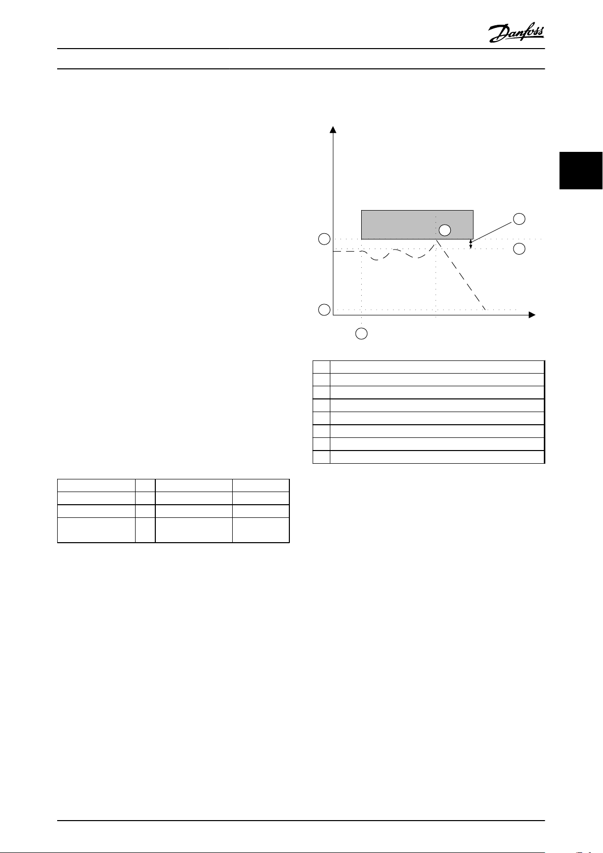
Illustration 3.14 Discrepancy Time
Parameterise the discrepancy time of the switching
elements connected to the digital inputs. The default value
is 10 ms.
22 Danfoss A/S © Rev. 2014-02-11 All rights reserved. MG34W302
Page 25

Input Signal
130BC317.10
DI1/DI2
Safety function
Active
Inactive
Test pulse pattern
Stable signal time Stable signal time
Functions and System Overvi...
Operating Instructions
NOTICE
The discrepancy time does not extend the safety option
response time. The safety option activates its safety
function as soon as one of the 2 DI signals changes from
high to low.
3.6.7 Stable Signal Time from Safe Outputs
The safety option normally responds immediately to signal
changes at its safe input DI1 or DI2. This response is not
required in the following cases
When interconnecting the safe input of the
•
option with an electromechanical sensor, contact
bounce may result in signal changes occurring, to
which the option could respond.
Several control modules test their safe outputs
•
using test pulse pattern (on/off tests), to identify
faults due to either short or cross circuiting.
When interconnecting the safe input of the
option with a safe output of a control module,
the option could respond to these test signals.
A signal change during a test pulse pattern usually lasts 1
ms.
Under stable signal time, short pulses, which could lead to
safety functions being incorrectly activated, can be filtered.
NOTICE
The stable signal time extends the safety option
response time. The safety option only activates the
safety function after the response time has expired.
Illustration 3.15 Filter for Suppressing Temporary Signal
Changes
Zero Speed Time Error Detection
3.6.8
Zero Speed Timer monitors if the frequency converter is
operated below 120 RPM during Safely Limited Speed.
42-18 Zero Speed Timer contains the remaining time until
the monitoring responds. The safety option signals Alarm
Ext Fail Prec Thresh Timer Elapsed after the monitoring time
expires.
Define the monitoring time while commissioning the
system depending on the particular application.
Yearly Test
3.6.9
3 3
If the signal to the input on safety option is not stable, the
option responds with a fault.
Definition of a stable signal
Following a change to the DI input signals, the option
triggers an internal monitoring time. Use 42-23 Stable
Signal Time to select an appropriate stable signal time. A
constant signal level is a high or a low state, for at least
42-23 Stable Signal Time.
MG34W302 Danfoss A/S © Rev. 2014-02-11 All rights reserved. 23
According to EN ISO 13849-1, EN IEC 62061 and EN IEC
61508, the safety option must regularly test its safetyrelevant circuits to ensure correct functioning. This test
must be performed at least once every year. After the
power supply has been connected, the safety option
checks its circuits to switch-off the torque each time the
Safe Torque Off function is selected. The safety option
monitors the regular test interval of its safety-relevant
circuits using a time module.
After one year in operation, the frequency converter
displays a message that a yearly test must be performed.
The frequency converter must be power cycled by disconnecting and then reconnecting the supply voltage. Activate
the used inputs on the safety option and check that they
function correctly.
3.6.10
Factory setting for both digital inputs is Safe Torque Off,
meaning that the Safe Output S37 is in low state.
Safety Parameter Settings
Page 26

Functions and System Overvi... Operating Instructions
At the first power up, the option shows Blank Initial State.
3.7.2
Compatibility between Safety and
Frequency Converter Functions
Properties of safety parameters
The safety option is compatible with all VLT
They are kept separate for each monitoring
•
33
A reset of the safety parameters to the factory setting can
be executed via MCT 10 Set-up Software.
channel.
During start-up, a checksum (Cyclic Redundancy
•
Check, CRC) over the safety parameters is
generated and checked. The parameters are
stored on the non-volatile memory on the option.
NOTICE
If the safety option is reinstalled in another frequency
converter, all safety parameters can be selected either
from the safety option or from the frequency converter
in which the option is now installed. A commissioning
test must always be performed to ensure the correct
functionality.
3.6.11 Encoder Interface
CAUTION
Some of the diagnostics performed on the encoder
signals require motion to detect faults. Make sure that
motion occurs at least once every 12 months.
To detect the standstill or the motor speed, the speed
(frequency) is measured using a TTL encoder (MCB 150), an
HTL encoder (MCB 151) or a PNP proximity switch (MCB
151). The HTL encoder uses 2 signal tracks, A and B. TTL
encoders uses 4 signal tracks A, B and their inverted tracks
nA, nB.
Use twisted-pair, individually screened cable to connect
encoders to the safety option.
3.7
Limitations
AutomationDrive FC 302 frequency converters in the range
of 0.37 kW to 75 kW. Compliance to higher power ranges
is to come. Contact the local supplier for latest
information.
MCB150/151 can be combined with the following Aoptions:
PROFIBUS MCB 101
•
DeviceNet MCA 104
•
CanOpen MCA 105
•
PROFINET MCA 120
•
Ethernet/IP MCA 121
•
Modbus TCP MCA 122
•
PowerLink MCA 123
•
EtherCAT MCA 124
•
The safety option is compatible with asynchronous and
synchronous (PM) motors. Asynchronous motors can be
used in U/f and VVC+ in closed and open loop as well as in
FLUX open loop control. Synchronous (PM) motors can be
used in U/f open or closed loop control. Compliance to
further motor types and control modes is to come. Contact
the local supplier for latest information.
The following software versions are required as minimum
for using MCB150/151:
LCP software version 7.0
•
VLT® AutomationDrive FC 302 Firmware Version
•
6.64
All frequency converters, options and control mode
combinations not listed above are not permitted.
®
3.7.1 Exceeded Limit Value and Internal
Errors
Exceeding set limit values activate the stop
•
braking ramp.
Any internal error on the safety option or
•
frequency converter activates the safety function
Safe Torque Off. The frequency converter coasts
the motor.
Internal errors always result in a fault, requiring a power
cycle of the frequency converter to reset the failure.
Alternatively, use 42-90 Restart Safe Option to restart the
safety option after internal failure without power cycling
the frequency converter.
24 Danfoss A/S © Rev. 2014-02-11 All rights reserved. MG34W302
Page 27

Installation
4 Installation
4.1 Installing the Safety Option
Operating Instructions
4.1.2
Protected Cable Installation
WARNING
Before start, disconnect the power supply voltage to the
frequency converter. Never install an option card into
the frequency converter during operation.
Ensure that all dangerous voltages connected from
external control circuits to the inputs and outputs of the
frequency converter are switched off. In addition to
conventional installation tools, have the Operating
Instructions for VLT® AutomationDrive FC 301/FC 302
and MCT 10 Set-up Software available as they contain
important information that is not included in this
manual.
The safety option is exclusively intended for use in
option slot B. The mounting position of B options is
shown in Illustration 4.1.
WARNING
ELECTRICAL HAZARD!
Safe Stop activation (Safe Torque Off) does not provide
electrical safety. The safety device connected to the dual
pole input of the safety option must fulfill the
requirements safety level for the application for
interrupting the voltage/current to safety option. This is
also valid for the connections between the safety
option’s safe output S37 and terminal T37 on the
frequency converter. To connect the safety device
correctly to the safety option, read and follow the
instructions.
If short circuits and cross circuits can be expected with
safety-related signals and if they are not detected by
upstream devices, protected cable installation is required
as per EN ISO 13849-2.
4.1.3 Installation
CAUTION
The VLT® AutomationDrive with safety option (including
the connection between output S37 (Y30/12 or Y31/12)
on MCB150/151 and X44/12 on the control card) must be
placed in an IP54 enclosure as per IEC 60529.
These step-by-step instructions describe how to mount the
control cables
4 4
4.1.1 Requirements for Safe Use
CAUTION
Ensure that the installation and wiring are EMCcompliant to avoid personal injury and damage to the
product.
Refer to the guidelines stated in this manual.
Also ensure compliance with
®
VLT
•
•
The safety option may only be used with the following
frequency converters
•
MG34W302 Danfoss A/S © Rev. 2014-02-11 All rights reserved. 25
AutomationDrive FC 301/FC 302 Operating
Instructions
Tool-Tip help for the configuration tool MCT 10
Safe Plug-in
VLT® AutomationDrive FC 302, power sizes from
0.37 kW to 75 kW, from SW Version 6.64
A A-option slot
B B-option slot
D D-option slot
Illustration 4.1 How to Fit the Safety Option
1. Disconnect power to the frequency converter.
2. Remove the LCP, the terminal cover, and the LCP
frame from the frequency converter.
Page 28
12/13
37
130BA874.10
130BT340.10
1
2
10 mm
130BD009.10
1
2
3
4
7
6
5
10
8
9
11
12
Installation Operating Instructions
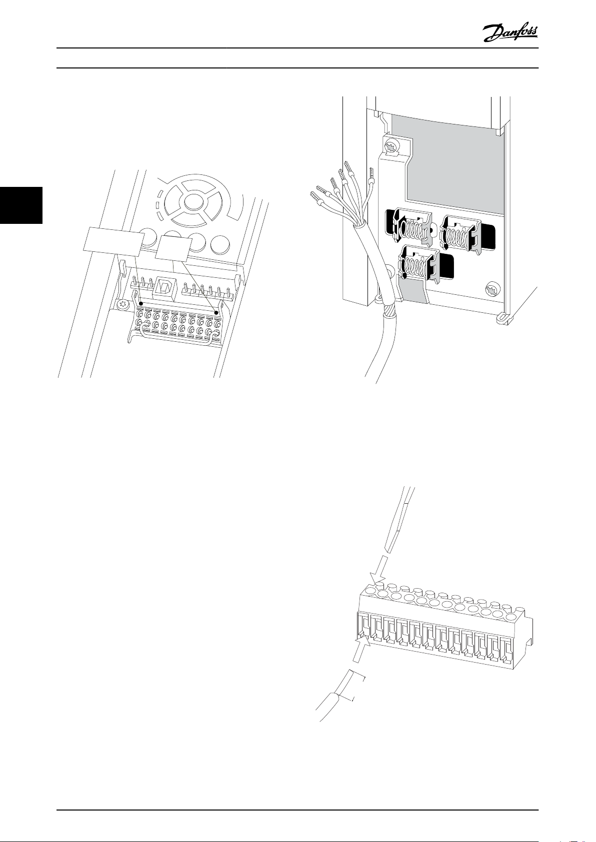
3. Fit the safety option in slot B.
4. Remove the jumper wire between control
terminals 37 and 12 or 13.
Cutting or breaking the jumper is not
•
sufficient to avoid short circuiting.
44
Illustration 4.2 Jumper between Terminal 12/13 (24 V) and 37
5. Connect the safe output S37 on the safety option
to terminal 37 on the control card (maximum
length of this wire is 10 cm).
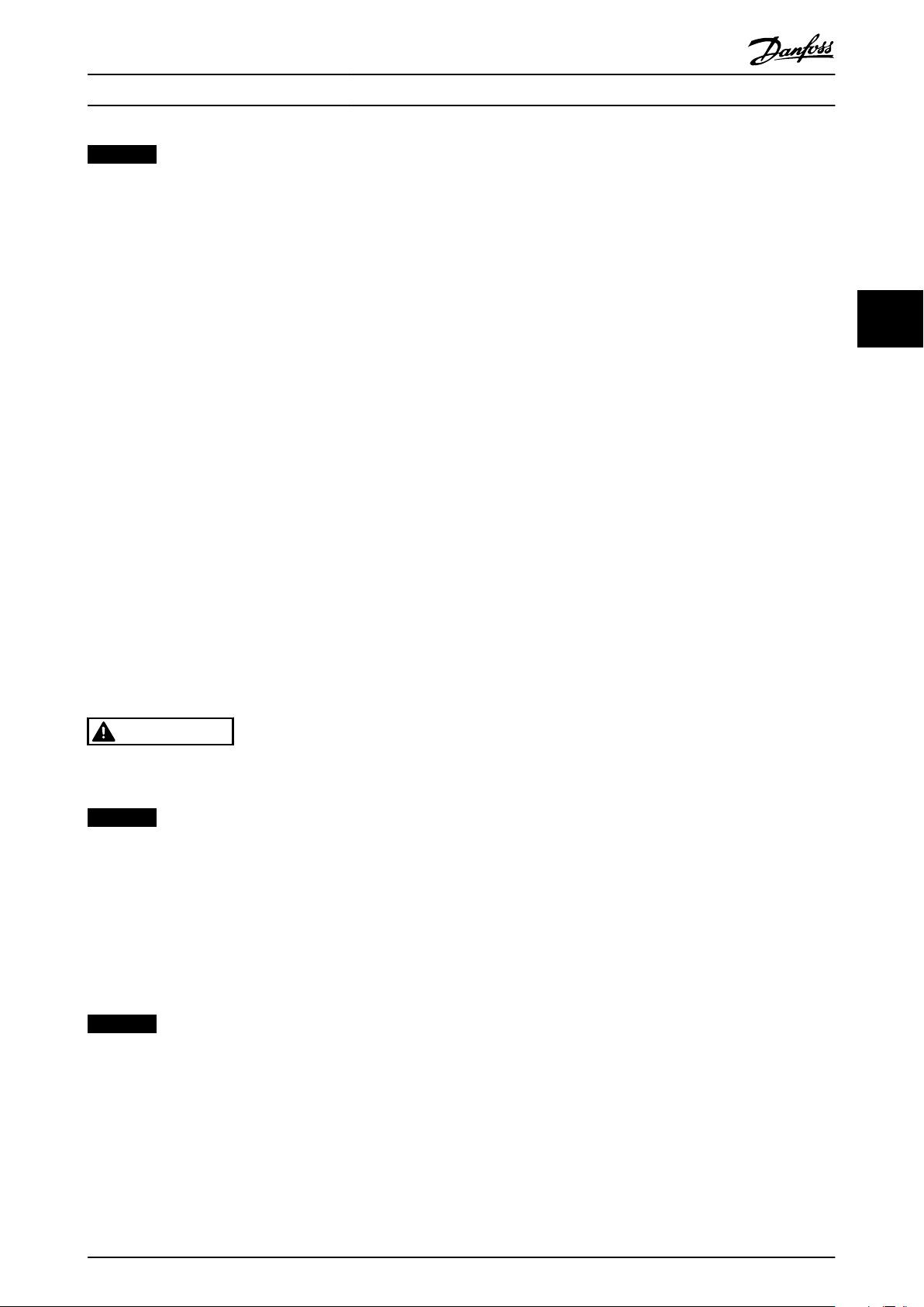
6. Connect the control cables to safety option and
relieve the cable by the enclosed cable strips.
Follow the guidelines in chapter 4.1.4 General
Wiring Guidelines.
Illustration 4.3 Connecting Screened Wire
7. Remove the knock-out in the extended LCP
frame, so that the option fits under the extended
LCP frame.
8. Fit the extended LCP frame and terminal cover.
26 Danfoss A/S © Rev. 2014-02-11 All rights reserved. MG34W302
Illustration 4.4 Connecting Control Wiring
Page 29
Installation Operating Instructions
NOTICE
The connections are not pre-wired from factory.
9. Fit the LCP or blind cover in the extended LCP
frame.
10. Connect power to the frequency converter.
11. Set up the input/output functions in the
corresponding parameters, as mentioned in the
manual for the Safe Plug-in in MCT 10
The commissioning test report is automatically generated
via the Safe Plug-in in MCT 10 after downloading the
parameters to the safety option.
CAUTION
The operator or electrical installer is responsible for
proper grounding and compliance with all applicable
national and local safety regulations.
4.1.4 General Wiring Guidelines
Inputs
Use appropriate wiring to exclude short circuits between
the inputs or to a supply line
Output
Use separate multicore cable for supply voltages to avoid
short circuits between the cable from the output (S37) to
the 24 V DC supply line
interruption with optimum screen support at
both ends
Connect screens at both ends to the grounded
•
enclosures through a good electrical connection
and through a large surface area
Connect cable screens as close as possible to the
•
cabinet cable entry
If at all possible, intermediate terminals should
•
not interrupt cable screens
Retain cable screens for both power cables as
•
well as for signal and data cables using the
appropriate EMC clamps. The screen clamps must
connect the screen to the EMC shield bar or the
screen support element for control cables
through a low inductive connection through a
large surface area.
4 4
CAUTION
As a result of short circuits, it is no longer possible to
switch off the frequency converter terminal 37.
NOTICE
Control cables must be screened/armoured.
See the section Earthing of Screened Control Cables in the
VLT® AutomationDrive Design Guide for detailed specifi-
cations.
Only screened cables are suitable for connecting encoders.
NOTICE
All signals to safety option must be PELV supplied and
comply with EN IEC 60204.
Route sensitive control cables - such as encoder
•
and active safety component cables - without any
MG34W302 Danfoss A/S © Rev. 2014-02-11 All rights reserved. 27
Page 30

1 2 3 4 5 6 7 8 9 10 11 12
130BC315.10
E30BC325.11
MCB 150
Safe Option
SW. ver. xx. xx
Option B
130B3280
LED:
123 4
TTL Enc. interface
Y30/
DI1 A
GND
DI1 B
ENC A
DI2 A
ENC nA
ENC B
DI2 B
ENC nB
24V
GND
S37
1 2 3 4 5 6 7 8 9 10 11 12
Installation Operating Instructions
4.1.5 Connector Pin Assignment
Y30 Pin Name Description
1 DI1 A Digital Input 1 A channel
2 GND Digital GND
3 DI1 B Digital Input 1 B channel
4 ENC A Encoder Channel A
5 DI2 A Digital Input 2 A channel
44
Table 4.1 Connector Pin Assignment, MCB 150
6 ENC nA Encoder Channel A inverted
7 ENC B Encoder Channel B
8 DI2 B Digital Input 2 B channel
9 ENC nB Encoder Channel B inverted
10 24 V Power output
11 GND Supply GND
12 S37 STO enable
Illustration 4.5 Nameplate MCB 150
28 Danfoss A/S © Rev. 2014-02-11 All rights reserved. MG34W302
Page 31
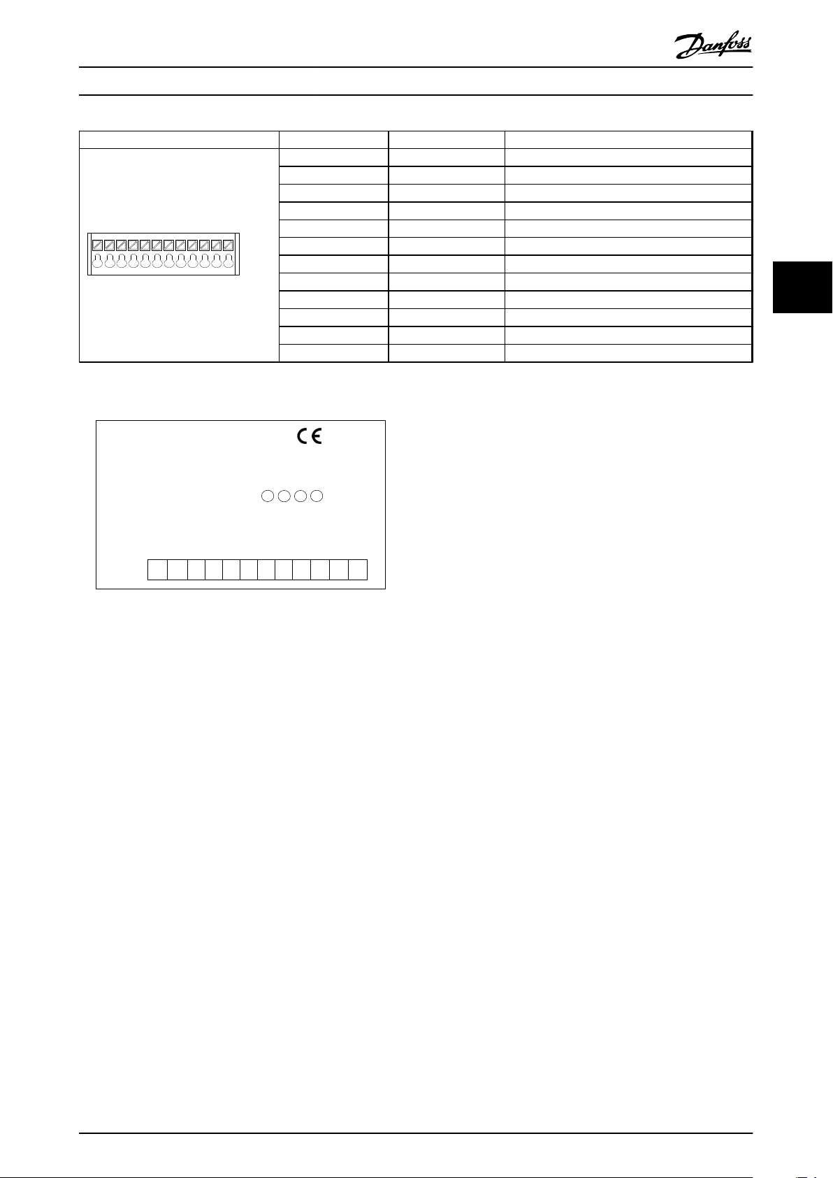
1 2 3 4 5 6 7 8 9 10 11 12
130BC315.10
E30BC326.11
MCB 151
Safe Option
SW. ver. xx. xx
Option B
130B3290
LED:
1
2
3 4
HTL Enc. interface
Y31/
DI1 A
GND
DI1 B
ENC A
DI2 A
ENC B
DI2 B
24V
GND
S37
1 2 3 4 5 6 7 8 9 10 11 12
GND
GND
Installation Operating Instructions
Y31 Pin Name Description
1 DI1 A Digital Input 1 A channel
2 GND Digital GND
3 DI1 B Digital Input 1 B channel
4 ENC A Encoder Channel A
5 DI2 A Digital Input 2 A channel
6 GND Digital GND
7 ENC B Encoder Channel B
8 DI2 B Digital Input 2 B channel
9 GND Digital GND
10 24 V Power output
11 GND Supply GND
12 S37 STO enable
Table 4.2 Connector Pin Assignment, MCB 151
4 4
Illustration 4.6 Nameplate MCB 151
MG34W302 Danfoss A/S © Rev. 2014-02-11 All rights reserved. 29
Page 32

130BC374.11
A
B
24V
GND
4
7
10
11
FC302
MCB151
130BC375.11
A
B
24V
GND
4
7
10
11
nA
6
nB 9
FC302
MCB150
Installation
Operating Instructions
4.2 Encoder
4.2.1 Permissible Encoder Cable Length
The permissible cable length depends on the selected
encoder. The longest cable can be achieved when using
bipolar TTL encoders.
Unipolar HTL encoders only permit a shorter length. In this
case, the encoder power supply voltage plays a decisive
44
role.
The maximum cable length for HTL encoders used as
unipolar encoder (in this case only one signal is evaluated)
is 100 m.
The maximum cable length for TTL encoders used as
bipolar encoder (in this case both signals A/nA or B/nB) is
150 m.
The minimum cross-section of the power supply conductor
is 0.75 mm2.
NOTICE
Routing of the sensor cables
All proximity switch sensor/encoder cables must be
screened when laid. The screen must be connected to
chassis at both ends. Always connect chassis on the
rotary encoder to chassis on the frequency converter.
CAUTION
The sensor connections must not be plugged in or
pulled off during operation. This could damage the
electrical components of the encoder. Always deenergise connected encoders and the safety option
before plugging in or pulling off encoder connections.
Lines twisted in pairs for signal transmission according
to RS-485 standard must be used for data signals or
track A and track B. The wire cross section must in each
individual case be chosen in compliance with the current
consumption of the encoder and the cable length
required for the installation.
Illustration 4.7 Y31/ Connecting Power and Encoder Signals to
HTL Encoder (MCB 151)
Illustration 4.8 Y30/ Connecting Power and Differential
Encoder Signals to TTL Encoder (MCB 150)
Illustration 4.8 shows TTL encoder with 24 V supply and
TTL output. If an encoder for 5 V supply must be
connected, use a 5 V external supply.
Proximity Switch
4.2.3
Diagnostics are performed on the encoder input signals. If
the encoder diagnostic tests fail, an error 99 (Safe State
fault) occurs.
An inductive proximity switch, detecting already present
mechanical parts, e.g. a gear wheel, is a frequently used
alternative to standard encoders. The required minimum
number of pulses per revolution (ppr) is 2 on the motor
shaft while considering the gear ratio.
4.2.2
Encoder Wiring Examples
Illustration 4.7 and Illustration 4.8 show examples of how to
connect encoder power and encoder signals.
30 Danfoss A/S © Rev. 2014-02-11 All rights reserved. MG34W302
Page 33

130BC376.11
A
24V
4
10
11GND
FC302
MCB151
>2x S
1
2
3
n
S /2
n
130BC314.10
130BC309.11
A
B
1
10
3
12
11
12
37
20
MCB15x
130BC310.11
1
24 V DC
3
12
11
12
37
20
MCB15x
0 V
OSSD 2
OSSD 1
Tx
Rx
A
Installation Operating Instructions
Illustration 4.9 Y/31 Connecting MCB 151 to Proximity Switch
(only HTL)
NOTICE
The proximity switch cable must be screened and
terminated to chassis at both ends (at the proximity
switch side and at the option side).
The operating distance S set to half the nominal operating
distance Sn, corresponds approximately to the optimum
conditions with respect to resolution and switching
frequency.
NOTICE
When using PNP proximity switch as encoder feedback,
set 42-14 Feedback Type to [1] Without direction info.
4 4
4.3 Application Examples
4.3.1 Connecting Safe Digital Inputs
The following pages contain examples of connecting the
fail-safe digital input according to EN ISO 13849-1 and EN
IEC 62061. The examples apply in cases where all
components are installed in a control cabinet.
A 2-channel emergency stop switch
B FC 302
Illustration 4.11 Connecting a Sensor, e.g. 2-channel
Emergency Stop Mushroom Push Button or Limit Switch
A FC 302
Illustration 4.12 Connecting an Electronic Sensor, e.g. Safety
Light Curtain
1 Measuring plate
2 Proximity switch
3 Disc (non conducting material)
Illustration 4.10 Gear Wheel for Proximity Switch
MG34W302 Danfoss A/S © Rev. 2014-02-11 All rights reserved. 31
Page 34

1
3
12
11
12
37
20
MCB15x
130BC311.11
10
C
B
A
1
12
11
12
37
20
MCB15x
130BC312.11
3
24 V DC
A
B
C
0 V
D
A
10
1
3
12
11
12
37
20
MCB15x
130BC313.11
B
130BC960.10
E-Stop
MCB 15 x
1
10
3
12
11
12
37
20
FC
12
37
20
FC
12
37
20
FC
Installation
Operating Instructions
NOTICE
Use of a 1-channel E-stop switch provides no input
redundancy, and no ability for the safety option to
monitor for input short circuits. One-channel E-stop
switches used with an safety option are suitable only for
Category 2 applications, per EN ISO 13849-1 PL c or SIL1.
When a 1-channel E-stop is used, guard against failure
44
A Actuator
B Switch
C FC 302
Illustration 4.13 Connecting 1 NO/1 NC Sensor, e.g. Magnetic
Switch
modes that can result in an unsafe condition. An example
of an unsafe condition could be the failure of the contact
to a short circuit condition. A switch with positive opening
operation should be used to reduce the possibility of a
failure of the switch to open. A short circuit failure results
in loss of switching function. This failure can occur from a
short across the switch contacts, a short across the wires
connected to the switch between the switch and the
safety option , or a short to a secondary source of power.
To reduce these risks, physically separate the wires from
each other and from other sources of power (e.g., in
separate wire ways or conduit). According to the definition
of European standard EN ISO 13849-1, a 1-channel E-stop
could be used in applications where PL c or less (b or a)
has been determined via a risk-assessment procedure.
A Safety PLC
B Safety output
C GND
D FC 302
Illustration 4.14 Connecting a Digital Output Module, e.g.
Safety PLC
A 1-channel emergency stop switch
B FC 302
Illustration 4.15 Connecting a Sensor, e.g. 1-channel
Emergency Stop Mushroom Pushbutton or Limit Switch
NOTICE
Illustration 4.16 Example of Multiple Frequency Converters in
Daisy Chain
All equipment used must be suitable for the selected
category/PL or SIL.
32 Danfoss A/S © Rev. 2014-02-11 All rights reserved. MG34W302
Up to 3 frequency converters may be connected in a daisy
chain. Total cable length must not exceed 30 m.
Page 35

Commissioning Operating Instructions
5 Commissioning
5.1 Before Commissioning
5.1.1 Safety Guidelines
When commissioning/recommissioning
Secure the site in accordance with regulations
•
(barrier, warnings, signs, etc.). Only qualified
personnel is allowed to commission/
recommission the system
Refer to the guidelines, information and specifi-
•
cations stated in the Operating Instructions of the
relevant programmable control system
Make sure that no personal injury and/or material
•
damage can occur, even if the plant/machine
moves unintentionally
CAUTION
ELECTROSTATIC DISCHARGE!
Electrostatic discharge can damage components. Ensure
discharge before touching the safety option, e.g. by
touching an earthed, conductive surface or by wearing
an earthed armband.
functions that are wired up to the safety option
inputs.
2. Ensure that the device number (serial number
and order number) of the safety option on the
frequency converter matches the device number
of the safety option in the MCT 10 Safe Plug-in.
3. Ensure that the frequency converter is ready for
commissioning (see VLT® AutomationDrive FC
301/FC 302 Operating Instructions)
The following components are required to perform the
necessary steps for commissioning the safety option.
MCT 10 Set-up Software (licensed version)
•
USB or fieldbus connection or RS-485 Interface
•
adaptor for connecting the control card of the
frequency converter with the PC
NOTICE
If RS-485 is used, the protocol for serial communication
needs to be set to [0] FC-MC in 8-30 Protocol (only
accessible through the LCP).
Observe the following
5 5
WARNING
RISK OF ELECTROCUTION!
Never wire the electrical connections on the frequency
converter while voltage is applied.
Switch off power.
Make sure that the control cabinet is provided with
access lock or warning signs.
DO NOT switch on the voltages until the system is
commissioned.
Refer to VLT® AutomationDrive FC 301/FC 302 Operating
Instructions for further information on the frequency
converter.
Refer to MCT 10 Set-up Software Operating Instructions for
further information on the Safe Plug-in.
Commissioning Requirements
5.1.2
The procedure requires installation of MCT 10 Set-up
Software, version 3.18 or later, and a successful connection
to VLT® AutomationDrive FC 302 with integrated safety
option.
1. Configure the safety option in the MCT 10 with
Safe Plug-in. Ensure only to configure safety
When setting up the option for the first time,
•
ensure to have a commissioning report at hand,
see further information in MCT 10 Set-up Software
Operating Instructions
NOTICE
Only LCP SW version 7.0 or newer is supported.
5.2 Initial Commissioning
5.2.1 Power-up/Self-test
Once the power supply has been applied to the frequency
converter, the safety option performs a self-test. During
the self-test phase, all LEDs light up (lamp test) and the
message Safe Opt. initialized - SO RESET requested or SO in
Self-test appears. After power-up, the LEDs light up
according to the device status.
NOTICE
If the supply voltage of the safety option exceeds the
permissible range, the safety function Safe Torque Off is
triggered. The safety-related output S37 on the option is
switched off.
MG34W302 Danfoss A/S © Rev. 2014-02-11 All rights reserved. 33
Page 36

130BD125.10
Status
SO Custom. requested
!1(1)
0 RPM None 0.00KW
!Safe Stop [W68]
130BD124.10
Status
SO Custom. aborted
SO RESET required!
!1(1)
0 RPM None 0.00KW
!Safe Stop [W68]
O Remote SO Req.RESET
130BD122.10
Status
SO Custom. completed
SO RESET required!
!1(1)
0 RPM None 0.00KW
!Safe Stop [W68]
O Remote SO Req.RESET
Commissioning
Operating Instructions
5.2.2 Initial Commissioning
1. Connect the configuration PC to the frequency
converter or motion control system
2. Switch on the supply voltages
55
3. Download configuration file
When the configuration file is downloaded, the LCP reads
“SO Custom. completed”.
The configuration is checked as it is downloaded.
Feasibility of the configuration data
•
Proper wiring
•
Correct device number (order number). If the self
•
test is successful, the frequency converter's power
element is enabled.
NOTICE
Up to 10 s may elapse before the safety option is ready
for operation.
34 Danfoss A/S © Rev. 2014-02-11 All rights reserved. MG34W302
1a Make the interface in the MCT 10 Safe
Plug-in (refer to the chapter Functional
Safety Configuration Plug-in in the MCT
10 Set-up Software Operating Instructions
and the Tool-Tip for help).
2a Switch on all the supply voltages for the
frequency converter and safety option
2b The display elements on the frequency
converter and on the safety option
show when they are ready for operation.
The display elements on the safety
option are described in
chapter 5.3 Operation.
3a Establish communication between the
PC and the frequency converter by
selecting Write to drive in the MCT 10
Safe Plug-in
3b Make sure that no other system is
accessing the interface
3c Apply password, unequal to default
password
3d On multi-axis systems the safety option
can be selected individually for the
download. The configuration is
distributed to the safety options via the
MCT 10.
5.2.3 Safety Option Customisation
LCP messages used to indicate the different states of the
customisation processes.
LCP message Description
MCT 10 Customisation of
safety option requested
MCT 10 Customisation of
safety option aborted
MCT 10 Customisation of
safety option complete
5.2.4 Setting up the Encoder
1.
Select the type of feedback device, either [1] Safe
Option or [0] None in 42-10 Measured Speed
Source. For SS1 time delay functionality no
feedback source is necessary.
2. Set the feedback parameters for the safety
option.
In closed-loop applications set
•
7-00 Speed PID Feedback Source to [11]
MCB 150/151
3.
Set Mounting Type to Motor shaft mounted or
Application mounted.
Select a gear ratio within 0.0001 -
•
32.0000 (default 1) in 42-13 Gear Ratio.
4. Set the correct encoder value (1-4096 PPR) in
42-11 Encoder Resolution.
5.
Set 42-12 Encoder Direction to [0] Clockwise
(default) or [1] Counter clockwise.
6.
Set 42-14 Feedback Type to [0] With direction info
or [1] Without direction info. Select [1] Without
direction info if proximity switch sensor is used for
speed detection.
Page 37

Commissioning
Operating Instructions
NOTICE
If the selected encoder resolution is below 150 PPR for
HTL/TTL encoder, set a feedback filter value in
42-15 Feedback Filter. The system then calculates an
allowed value. This is also the case when using a
proximity switch feedback where the encoder resolution
is below 600 PPR.
at initial start-up of the safety function
•
after any changes related to the safety function
•
(wiring, components, settings, etc.)
after any maintenance work related to the safety
•
function.
5.3 Operation
NOTICE
Depending on the system, a movement can imply
different directions for the motor encoder.
NOTICE
Depending on the application, the motor encoder may
be connected via a gearbox.
5.2.5 Commissioning Test
The MCT 10 Safe Plug-in creates a commissioning report
based on the commissioning test result. It generates the
frequency converter safety signature. This function
provides a final report when the safety option has been
configured. This report is considered as a help tool for
safety commissioning and validates that all the safety
functions are operational. The commissioning report can
either be printed or converted into a PDF file.
The test objective is to verify proper implementation
(forced dormant error detection measures) and to examine
the response of specific monitoring functions to the
explicit input of values outside tolerance limits.
WARNING
After hardware and/or software components have been
modified or replaced, all protective equipment must be
closed before system start-up and activation of the
frequency converter. Personnel must keep out of the
danger zone. It is mandatory to carry out a partial or
complete commissioning test after having made certain
changes or replacements. Before allowing anybody to reenter the danger zone, test the steady control response
by briefly moving the frequency converters in forward
and reverse direction (±).
WARNING
UNINTENDED BEHAVIOUR
Numerous stored data or settings govern the behaviour
of the frequency converter system. Unsuitable settings or
data may trigger unexpected movements or responses to
signals and disable monitoring functions.
Do NOT operate the frequency converter system
•
with unknown settings or data
Verify that the stored data and settings are
•
correct
When commissioning, carefully run tests for all
•
operating states and potential error situations
Verify the functions after replacing the product
•
and also after changing the settings or data
Only start the system if there are no persons or
•
obstructions in the hazardous area
Failure to follow these instructions can result in death,
serious injury or equipment damage.
Prerequisites for normal operation are
commissioning is complete
•
the safety option contains the configuration data
•
the safety functions have been tested
•
LED1, LED2 and LED4 are lit
•
During operation
any pulse edge change at the safety option safe
•
input is monitored
the safety functions are performed in accordance
•
with the configuration
5 5
EN IEC 61508, EN IEC 62061 and EN ISO 13849 require that
the final assembler of the machine validates the operation
of the safety function with a commissioning test. The
commissioning tests for the standard safety functions Safe
Stop of the frequency converter are described in the
frequency converter manuals. The tests for the optional
safety functions are described in the commissioning report
generated by the MCT 10 Safe Plug-in. The commissioning
test must be performed
MG34W302 Danfoss A/S © Rev. 2014-02-11 All rights reserved. 35
Page 38

General Parameter Set-up Operating Instructions
6 General Parameter Set-up
6.1 Configuration
6.1.1 General Parameter Set-up
See chapter 6.3 Parameter List to configure an operation of
the safety option. The set-up is done via MCT 10 Safe Plugin.
Speed monitoring by the safety option
If an external encoder is connected to the safety option
and selected in 42-10 Measured Speed Source, speed
66
monitoring is active all the time whether a safety function
is requested or not. However, if a Safe Torque Off is
triggered (either directly, or as a consequence of a Safe
Stop 1) it interrupts the speed monitoring.
Encoder Configuration
To define the type of feedback used by the safety option,
select [1] Safe option in 42-10 Measured Speed Source.
Safety Functions Configuration
6.1.2
The safety functions to be carried out by the safety option
are defined in the MCT 10 Safe Plug-in.
Configurations of the safety functions
•
Setting of limit values, braking ramps for the
•
safety functions, monitoring of motion sequences
The safety option is configured with the commissioning
software MCT 10 Set-up Software via a Safe Plug-in. The
Safe Plug-in in the commissioning software is available as
default from version 3.18.
The commissioning software provides the following menu
items for the safety option.
General Speed Monitoring
•
Safe Input
•
Safe Stop 1
•
Safely Limited Speed
•
Parameters
•
Status
•
The menu items are described in detail in the MCT 10 Setup Software Operating Instruction.
The menu item Status shows the following
Current signal states of inputs and output
•
Option operating mode
•
Active safety function
•
The states of the inputs and output cannot be changed via
the commissioning software.
NOTICE
Always perform the required commissioning test. The
commissioning test report is automatically generated via
the Safe Plug-in in MCT 10 after downloading the
parameters to the safety option.
Downloading the configuration to safety option.
On single-drive systems, via the RS-485/USB
•
interface on the frequency converter
On networked systems, via the RS-485 or fieldbus
•
interface on the MCT 10 Safe Plug-in. The control
system passes the configuration to the respective
safety option
The feasibility of the configuration is checked
•
when it is downloaded
Further information on configuration and setting
parameters for the safety functions is available in the
online help for the MCT 10 Safe Plug-in and in the MCT 10
Set-up Software Operating Instructions.
Password Protection
6.1.3
Use a password to protect the system configuration. A
password must be entered only when changing safety
option parameters (writing to option).
Default password is 12345678.
It is advised to change the safety option default password
before downloading the parameter values of a safety
option with factory settings. Only persons knowing the
password can change the safety option parameter values.
36 Danfoss A/S © Rev. 2014-02-11 All rights reserved. MG34W302
Page 39

General Parameter Set-up Operating Instructions
NOTICE
Any misuse of password may lead to severe safety
problems.
NOTICE
No password is required to access the commissioning
parameters of the safety option. The password is
required when the parameters must be downloaded to
the option via Write to Drive.
The password must be of 8 characters and is casesensitive. Alphanumeric characters and symbols are valid
for password.
The safety option checks the parameter password entered.
Use the menu item Change Password to change the safety
option parameter password. Change the safety option
password if there is any indication of manipulation.
6.1.3.1
Password Forgotten
NOTICE
Resetting the password resets all option parameters to
factory default.
NOTICE
The frequency converter specific alarms are not reset
and the control word profile is overwritten.
6.2.2 Retrieving Safety Option Status
A subset of the safety option status can be retrieved as
part of the status word. It's behaviour changes based on
the selected control word profile.
Configure [91] Safe Opt. Reset. req, and [90] Safe Function
active in 8-13 Configurable Status Word STW to
Indicate that a reset of the safety option is
•
required
Indicate that a safe function is active
•
42-80 Safe Option Status indicates the actual status (active
safe function, any requests and error number) of the safety
option and is accessible as read only parameter from any
interface or configurable as read process data for a specific
fieldbus.
CAUTION
Only active safe function is set in Safety Option Status.
6 6
Forgot the safety option parameter password?
Select [Reset] in [Administration]
•
Checkmark "Yes, I want to reset Safe Option
•
configuration in the drive"
Enter default password (12345678)
•
Click "Reset"
•
On the prompt that appears click "yes"
•
Change the safety option password
•
6.2
Reset and Status over Fieldbus
6.2.1 Reset of Safety Option and Pending
Safe Function
There are 2 different methods of performing a reset of the
safety option and pending safe function. The configuration
of 42-31 Reset Source is decisive for which method to use.
If 42-31 Reset Source is set to [0] Drive Reset, a reset
according to the selected control word profile is required.
NOTICE
The frequency converter specific alarms are also reset.
If 42-31 Reset Source is set to [1] Drive Safe Reset, [3] Safe
Option Reset must be configured in 8-14 Configurable
Control Word CTW.
Bit Description
0 Normal_up
1 PUST
2 STO active
3 SS1-a active
4 SS1-b active
5 SLS-a active
6 SLS-b active
7 Reserved for further SF
8 Reserved for further SF
9 Reserved for further SF
10 Reserved for further SF
11 Int_fail
12 Reset required
13 Pending fail safe state
14 Ext_fail
15 Safe function pending
16 General reset
17 Customisation_confirmed
18 Customisation_aborted
19 Customisation_requested
20 Suspension of speed monitoring
21 PUST warning
22 DI_1_offline_warning
23 DI_2_offline_warning
24 Error code
25 Error code
MG34W302 Danfoss A/S © Rev. 2014-02-11 All rights reserved. 37
Page 40

General Parameter Set-up Operating Instructions
Bit Description
26 Error code
27 Error code
28 Error code
29 Error code
30 Error code
31 Error code
Table 6.1 Explanation of the Status Bits for Safety Option Status
Bit 00, Safety function deactive/active
Bit 00 = "0", "Safety function, fail safe reaction is active or
pending or warning is active"
Bit 00 = "1", Normal Operation.
66
Bit 01, Power Up Self Test
Bit 01 = "1", Safety option is in PUST state.
Bit 02, Safe Torque Off
Bit 02 = "0", Safe Torque Off is not active.
Bit 02 = "1", Safe Torque Off is active.
Bit 03, Safe Stop 1 a
Bit 03 = "0", Safe Stop 1-a is not active.
Bit 03 = "1", Safe Stop 1-a is active.
Bit 04, Safe Stop 1 b
Bit 04 = "0", Safe Stop 1-b is not active.
Bit 04 = "1", Safe Stop 1-b is active.
Bit 05, Safely Limited Speed a
Bit 05 = "0", Safely Limited Speed-a is not active.
Bit 05 = "1", Safely Limited Speed-a is active.
Bit 06, Safely Limited Speed b
Bit 06 = "0", Safely Limited Speed-b is not active.
Bit 06 = "1", Safely Limited Speed-b is active.
Bit 07-10
For future safety functions reserved
Bit 11, Internal failure
Bit 11 = "0", No Internal failure is active.
Bit 11 = "1", Internal failure is active.
Bit 12, Reset
Bit 12 = "0", No Safety option reset required
Bit 12 = "1", Safety option reset required
Bit 13, Pending fail safe state
Bit 13 = "0", No pending fail safe state
Bit 13 = "1", Safety option is in this state at each power up.
Bit 14, External failure
Bit 14 = "0", No External failure is active.
Bit 14 = "1", External failure is active.
Bit 15, Safe function pending
Bit 15 = "0", No Safe function pending
Bit 15 = "1", Safe function pending
Bit 16, General Reset
Bit 16 = "0", No change in state
Bit 16 = "1", General Reset is done
Bit 17, Customisation confirmed
Bit 17 = "0", No change in state
Bit 17 = "1", Customisation confirmed by user
Bit 18, Customisation aborted
Bit 18 = "0", No change in state
Bit 18 = "1", Customisation aborted by user
Bit 19, Customisation requested
Bit 19 = "0", No change in state
Bit 19 = "1", Customisation is requested by user
Bit 20, Suspension of speed monitoring
Bit 20 = "0", No change in state
Bit 20 = "1", Suspension of speed monitoring – see error
code
Bit 21, Power Up Self Test Warning
Bit 21 = "0", No change in state
Bit 21 = "1", Power Up Self Test Warning is issued
Bit 22, Digital Input 1 Offline Test Warning
Bit 22 = "0", No change in state
Bit 22 = "1", Digital Input 1 Offline Test Warning
Bit 23, Digital Input 2 Offline Test Warning
Bit 23 = "0", No change in state
Bit 23 = "1", Digital Input 2 Offline Test Warning
Bit 24-31
It contains reason for possible internal errors or external
errors – see error code
42-81 Safe Option Status 2 indicates which digital input of
the safety option is either activated, in pending state or in
blank initial state.
38 Danfoss A/S © Rev. 2014-02-11 All rights reserved. MG34W302
Page 41

General Parameter Set-up Operating Instructions
Bit Description State
0
1
2
3
4 Blank initial state 0 (inactive)/1 (active)
5
31
Table 6.2 Explanation fo the Status Bits for Safety Option Status 2
DI1 Safety Status
DI2 Safety Status
Unused
00 - Inactive
01 - Active
10 - Pending
00 - Inactive
01 - Active
10 - Pending
Bit 00-01, DI1 Safety Status
Bit 00-01 = “00” Inactive
Bit 00-01 = “01” Active
Bit 00-01 = “10” Pending
Bit 02-03, DI2 Safety Status
Bit 00-01 = “00” Inactive
Bit 00-01 = “01” Active
Bit 00-01 = “10”
Pending Bit 04, Blank Initial Status
Bit 04 = “0” Safety option is configured
Bit 04 – “1” Safety option is in blank initial state
Bit 05-31
Reserved for future use
6 6
MG34W302 Danfoss A/S © Rev. 2014-02-11 All rights reserved. 39
Page 42

General Parameter Set-up Operating Instructions
6.3 Parameter List
All parameters except 42-90 Restart Safe Option are read only.
Refer to VLT
type.
®
AutomationDrive FC 302 Programming Guide for general information about usage of conversion index and data
66
40 Danfoss A/S © Rev. 2014-02-11 All rights reserved. MG34W302
Page 43

General Parameter Set-up Operating Instructions
Group Group Name Parameter Value range/
available choices
42-1* Speed
Monitoring
42-11 Encoder
42-12 Encoder
42-13 Gear Ratio 0.0001 - 32.0000 1 Ratio between motor
42-14 Feedback
42-15 Feedback
42-18 Zero Speed
42-19 Zero Speed
42-10 Measured
Speed Source
Resolution
Direction
Type
Filter
Timer
Limit
[0] None
[1] Safe Option
1 - 4096 ppr (for
option with HTL
encoder)
1 - 10000 ppr (for
option with TTL
encoder)
[0] Clockwise
[1] Counter
clockwise
[0] With direction
info
[1] Without
direction info
0.01 - 200.00 Hz 200 Hz Frequency of the
0 - 10000 h 8760 h Time period where
Fixed 120 RPM 67 u_int16
Default Description Conversion
index
[1] Safe Option The source of the
speed feedback.
1024 ppr Encoder or proximity
switch resolution of
the encoder
connected to the
MCB 150 TTL and
MCB 151 HTL.
[0] Clockwise Allows for changing
the detected encoder
rotation direction
without changing the
wiring to the
encoder.
speed and encoder
speed. Remark: Only
used when gear
mounted.
[0] With
direction info
The feedback can be
with or without
direction information.
For TTL/HTL encoder,
direction info is
available. For
proximity switch,
select [1] Without
Direction Info.
feedback filter.
Default value is 200
Hz (off) if the
encoder resolution is
higher than 150 ppr.
A filter value of 200
Hz is selected,
meaning that the
filter is off. The use of
filters depends on
the given encoder
resolution, gear ratio
and feedback type.
the option is allowed
to be below 120 RPM
when SLS is active
before STO is
activated.
- u_int8
0 u_int16
- u_int8
-4 u_int32
- u_int8
-2 u_int16
74 u_int16
Data type
6 6
MG34W302 Danfoss A/S © Rev. 2014-02-11 All rights reserved. 41
Page 44

General Parameter Set-up Operating Instructions
Group Group Name Parameter Value range/
available choices
42-2* Safe Input 42-20 Safe Function [0] STO
[1] SS1-a
[2] SS1-b
[3] SLS-a
[4] SLS-b
[5] disable
42-21 Type [0] NCNC
[1] Antivalent
[2] NC
42-22 Discrepancy
Time
66
42-3* General 42-30 External
42-23 Stable Signal
Time
42-24 Restart
Behaviour
Failure Reaction
42-31 Reset Source [0] Drive Reset
42-33 Parameter Set
Name
0 - 5000 ms 10 ms An adjustable filter
0 - 5000 ms 10 ms An adjustable signal
[0] Manual
[1] Automatic
[0] STO
[1] SS1-a
[2] SS1-b
[1] Drive Safe Reset
[2] Safe Option
DI2_A
Visible String,
length: 8
Default Description Conversion
index
[0] STO This can be one of
the safety functions
or disabled. Remark:
Both Safe Inputs can
NOT be disabled at
the same time!
[0] NCNC NCNC, antivalent
(NC/NO) or 1NC.
time prevents faults
caused by temporary
discrepancy.
filter in the safety
option suppresses
temporary signal
changes using test
pulse pattern.
[0] Manual In case of an
activated safety
function, the safety
option can either
restart automatically
or wait for a RESET
signal from the user.
[0] STO Safety function that is
executed in case of
an external failure.
[0] Drive Reset Source for the RESET
of the safety option.
Can either be
executed on the
option input DI2, via
fieldbus or digital
input on the
frequency converter
or via the LCP. By
selecting Drive Safe
Reset, only the safety
option is reset.
SafeSet1 Name of the safe
parameter Set (must
be 8 characters to
avoid a bad customi-
sation data error).
- u_int8
- u_int8
-3 u_int16
-3 u_int16
- u_int8
- u_int8
- u_int8
Data type
42 Danfoss A/S © Rev. 2014-02-11 All rights reserved. MG34W302
Page 45
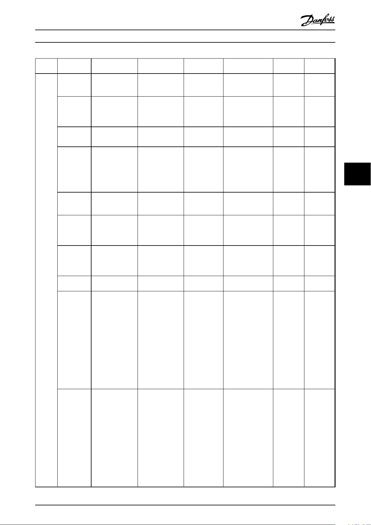
General Parameter Set-up Operating Instructions
Group Group Name Parameter Value range/
available choices
42-4* SS1 42-40 Type [0] Delay
[1] Ramp (slope)
[2] Ramp (time)
42-41 Ramp Profile [0] Linear
[2] S-ramp Const
Time
42-42 Delay Time 0.1 - 3600.0 s 1.0 s Time until STO is
42-43 Delta T 0 - 99 % 2%
42-44 Deceleration
Rate
42-45 Delta V 1 - 10000 RPM 120 RPM Tolerance between
42-46 Zero Speed 1 - 600 RPM 10 RPM When this speed is
42-47 Ramp Time 0.1 - 3600.0 s 1.0 s Time to ramp down
42-48 S-ramp Ratio
at Decel. Start
42-49 S-ramp Ratio
at Decel. End
1 - 30000 RPM/s 1500 RPM/s Deceleration rate for
1 to (100 - 42-49 Sramp Ratio at
Decel. End) %
1 to (100 - 42-48) % 50% The proportion of the
Default Description Conversion
index
[0] Delay The type of the SS1
Safety Function.
[0] Safe Option
Linear
50% The proportion of the
The ramp profile for
a SS1 Delay can be
either specified as
linear or S-ramp.
activated
Δ T subtracts from
the time in
42-42 Delay Time to
get motor to stop
before the timer
expires.
the SS1 slope based
ramp type.
calculated and actual
speed that the safety
option allows.
reached, the safety
option activates the
STO.
to 0 RPM
total ramp-down time
(42-42 Delay Time)
where the
deceleration torque
increases. The larger
the percentage value,
the greater the jerk
compensation
achieved, and thus
the lower the torque
jerks in the
application.
total ramp-down time
(42-42 Delay Time)
where the
deceleration torque
decreases. The larger
the percentage value,
the greater the jerk
compensation
achieved, and thus
the lower the torque
jerks in the
application.
- u_int8
- u_int8
-1 u_int16
0 u_int8
0 u_int16
67 u_int16
67 u_int16
-1 u_int16
0 u_int8
0 u_int8
Data type
6 6
MG34W302 Danfoss A/S © Rev. 2014-02-11 All rights reserved. 43
Page 46
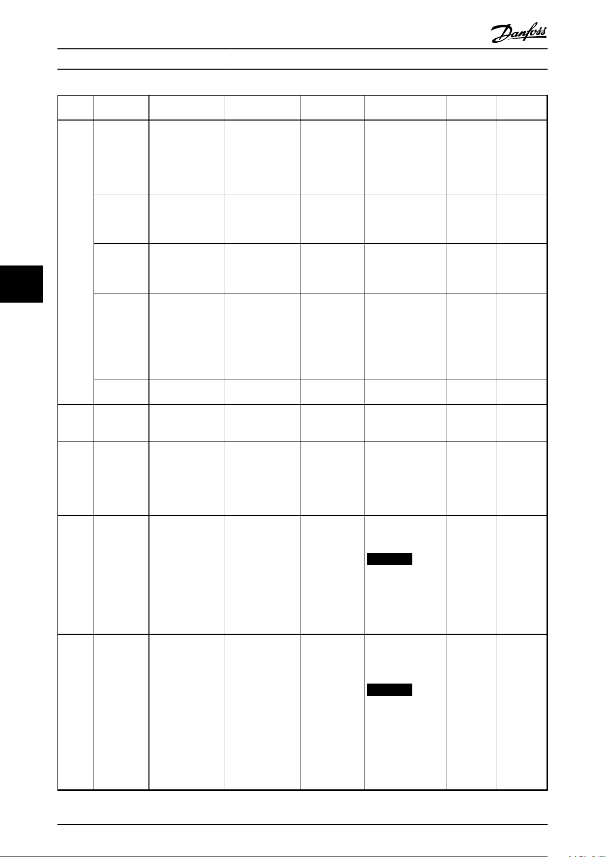
General Parameter Set-up Operating Instructions
Group Group Name Parameter Value range/
available choices
42-5* SLS 42-50 Cut Off Speed (42-51 + 1) to
10000 RPM
42-51 Speed Limit 0 to (42-50 - 1)
RPM
42-52 Fail Safe
Reaction
[0] STO
[1] SS1-a
[2] SS1-b
66
42-53 Start Ramp [0] No
[1] Yes
42-54 Ramp Down
Time
42-8* Status 42-80 Safe Option
Status
42-81 Safe Option
Status 2
42-85 Active Safe
Func.
0.1 - 3600.0 s 1.0 s Ramp-down time for
0 - 4294967295 0 Shows the safety
0 - 2147483647 0 Shows the safety
[0] STO
•
[1] SS1-a
•
[2] SS1-b
•
[3] SLS-a
•
[4] SLS-b
•
Default Description Conversion
index
270 RPM Speed at which the
fail safe reaction gets
activated. This should
be the value of
42-51 Speed Limit plus
a tolerance.
150 RPM Maximum speed
allowed when the
SLS function is
active.
[0] STO Safety function that is
activated, if the
speed exceeds the
limit. Only for SLS.
[0] No If the speed at
activation of SLS is
higher than the
speed limit, it ramps
down to the speed
limit (yes) or activate
an STO (no).
start ramp.
option status word as
a hexadecimal value.
option status 2 as a
hexadecimal value.
e.g. it contains DI1,
DI2 and blank initial
state status.
None Shows the currently
active safe function.
Can be used on LCP.
67 u_int16
67 u_int16
- u_int8
- u_int8
-1 u_int16
0 u_int32
0 u_int32
- u_int8
NOTICE
Can only be
selected in
Data type
parameters 0-20
to 0-22.
42-86 Safe Option
Info
0 - None, if no safe
function is active
0 Shows information
about the safety
option. Can be used
on LCP.
0
NOTICE
Can only be
selected in
0-23 Display Line 2
Large and
0-24 Display Line 3
Large.
44 Danfoss A/S © Rev. 2014-02-11 All rights reserved. MG34W302
Page 47

General Parameter Set-up Operating Instructions
Group Group Name Parameter Value range/
available choices
42-89 Customi-
zation File Version
42-9* Special 42-90 Restart Safe
Option
Table 6.3 Safety Option Parameters
®
Refer to VLT
AutomationDrive FC 301/FC 302 Operating Instructions for a comprehensive parameter list.
0.00 - 99.99 1.00 Stores the customi-
[0] No
[1] Yes
Default Description Conversion
index
-2 u_int16
sation file version.
[0] No Possibility to restart
option after internal
failure without power
cycling the frequency
converter.
- u_int8
Data type
6 6
MG34W302 Danfoss A/S © Rev. 2014-02-11 All rights reserved. 45
Page 48

Service and Repair
7 Service and Repair
Operating Instructions
7.1 Updates, Servicing and Modifications
NOTICE
Updates to Firmware
Contact Danfoss to get an update of the firmware.
CAUTION
Firmware Modifications
Only Danfoss is authorized to change the firmware. If
other parties make changes to the firmware, the
warranty expires. Furthermore, Danfoss cannot be held
liable for any consequences the changes may have on
the functional safety.
77
CAUTION
Modifications to the Unit
Only Danfoss is allowed to make hardware modifications
of the safety option. If other parties make changes to
the unit, the warranty expires. Furthermore, Danfoss
cannot be held liable for any consequences the changes
may have on the functional safety.
CAUTION
Servicing
Once a year, check that the safety option functions
properly to ensure the safety of the machine. Perform
the check by either
testing the function, or
•
switching off the options used in the safety
•
chain
7.3
Replacing
7.3.1 Removing the Safety Option
Before removing the safety option
1.
Save all parameters of the safety option, see MCT
10 Set-up Software Operating Instructions.
2. Duplicate the existing device setting.
NOTICE
The frequency converter generates an error message
after removing the safety option.
How to remove the safety option
1. Disconnect all power (power stage supply voltage
and controller supply) before plugging in or
removing the option.
2. Verify that no voltage is present.
3. Remove the safety option according to the
instructions in Installation in VLT
AutomationDrive FC 301/FC 302 Operating
Instructions.
®
NOTICE
If the removed safety module is installed in another
frequency converter, the frequency converter issues a
warning for safety option parameter selection. The user
can then select the safety configuration from either the
frequency converter or from the Safety Option.
7.3.2 Replacing the Safety Option
WARNING
ELECTRICAL SHOCK HAZARD!
7.2 Repair
Always disconnect mains supply to the frequency
converter before removing the safety option.
WARNING
When replacing the safety option, note the following
ELECTRICAL SHOCK HAZARD!
Always disconnect mains supply to the frequency
converter before removing the safety option.
Only Danfoss is authorised to make repair to the safety
option. A defect option must be shipped back to Danfoss.
Alternatively, copy the safe parameters using a graphical
LCP, see chapter 7.3.3 Copying Safe Parameter Set-up.
46 Danfoss A/S © Rev. 2014-02-11 All rights reserved. MG34W302
If the firmware version has changed, configured
•
functions and stated parameters may no longer
be supported or may have been modified. Adapt
the configuration in the MCT 10 Set-up Software.
Download the configuration to the safety option
•
again
Page 49

Service and Repair Operating Instructions
NOTICE
Option Change (Alarm 67) detection informs that a
change of the frequency converter hardware configuration has occurred after a power-up. This situation
could occur after installing/removing an option, or if an
option is defect. If the configuration changes, the
frequency converter freezes the hardware configuration,
trips and refuses to start up, thus avoiding any
unintended parameter changes.
Reset all option parameters to factory settings to avoid this
trip.
1. Order a new safety option at Danfoss.
2.
Replace the defective option, see chapter 4 Instal-
lation.
At the first power-up, the frequency converter recognises
different configurations between the safety option and the
frequency converter if the safety option parameters are not
set to default.
3.
Select Frequency converter.
4. If configured, enter the password for the copied
SO configuration from LCP.
5. Accept to download the safe parameters to the
frequency converter/safety option.
6.
Select OK.
7. Restart the frequency converter.
After replacing the safety option, download the configuration data again, either from
1. Prepare a commissioning report.
2.
Select [1] All to LCP in 0-50 LCP Copy. Monitor the
upload on the progress bar.
3. Install the LCP with all the copied parameters on
the frequency converter that needs to be
updated.
4.
Select [2] All from LCP in 0-50 LCP Copy. The
normal password protection can be applied in
0-60 Main Menu Password.
5. Enter the password for copied SO configuration
(= safe parameters) from LCP).
6. Accept the download of the safe parameters to
the frequency converter, which now has a new
configuration assigned to it.
7. Reset the frequency converter to activate the new
configuration.
Password protection LCP copy and safe parameter
mismatch
Optionally, a password protection can be used for the
function LCP-copy (see Table 7.1) and in case of a
parameter mismatch (see Table 7.2). Password protection
can be enabled/disabled in 0-69 Password Protection of
Safety Parameters. The password is set in 0-68 Safety
Parameters Password. Default password is 300.
7 7
MCT 10 Safe Plug-in to the safety option via
•
RS-485 or USB
an LCP in the frequency converter to the safety
•
option
A checksum is saved along with the file to allow for identification for the duplicated safety option parameters. Follow
the guided sequence on the LCP display to transfer the
safety option parameters to a safety option.
Verify that the correct safety parameter file is transferred to
the safety option.
Perform a commissioning test, see chapter 5.2.5 Commis-
sioning Test.
7.3.3
Copying Safe Parameter Set-up
To copy the safe parameter set-up to another frequency
converter
MG34W302 Danfoss A/S © Rev. 2014-02-11 All rights reserved. 47
Page 50

130BD114.10
Password
0-69 Password Protection
of safety Parameter
1(1)
0 RPM None
[1] Enabled
([0] Disabled)
130BD116.10
Copy/Save
0-50 LCP Copy
1(1)
0 RPM None
Safety Par. from LCP
0-5
*
9[ ]
130BD117.10
Safety Par. from LCP
1(1)
0 RPM None
Copying...
00%
130BD118.10
Safety Password
Please enter the safety
Password
1(1)
0 RPM None
0000000
0
130BD119.10
1(1)
0 RPM None
Password accepted
Pa
0-
[0
([1] Enabled)
130BD123.10
1(1)
0 RPM None
Password rejected
Pa
0-
[0
([1] Enabled)
Service and Repair Operating Instructions
LCP Copy
Message Description
The password protection of the safety parameters is enabled.
Copying the safety parameters from the LCP into the frequency converter is selected.
77
The safety parameters get copied from the LCP into the frequency converter.
If password protection is enabled in 0-69 Password Protection of Safety Parameters, enter the correct
LCP-copy/parameter mismatch password (0-68 Safety Parameters Password).
If the entered password is correct, this overlay message is shown for some seconds.
If the entered password is wrong, this overlay message is shown for some seconds. Then the password
can be entered again.
48 Danfoss A/S © Rev. 2014-02-11 All rights reserved. MG34W302
Page 51

130BD120.10
SO Data Conrmation
Are you sure that you want
to overwrite the safety
parameters including the
level 1 password?
!1(1)
0 RPM 0.00A
130BD121.10
SO Data Conrmation
Press [OK] to conrm
(commissioning test must be
performed) or [CANCEL] to
abort
!1(1)
0 RPM 0.00A
130BD122.10
Status
SO Custom. completed
SO RESET required!
!1(1)
0 RPM None 0.00KW
!Safe Stop [W68]
O Remote SO Req.RESET
130BD124.10
Status
SO Custom. aborted
SO RESET required!
!1(1)
0 RPM None 0.00KW
!Safe Stop [W68]
O Remote SO Req.RESET
130BD115.10
SO Param. Selection
Mismatch of SO param.set
detected. Please choose:
!1(1)
0 RPM 0.00 A
SO : Test1234_ 1.00
VLT : SafeSet1_ 1.00
130BD122.10
Status
SO Custom. completed
SO RESET required!
!1(1)
0 RPM None 0.00KW
!Safe Stop [W68]
O Remote SO Req.RESET
Service and Repair Operating Instructions
Message Description
Decision box for continuing overwriting the existing data or to abort the procedure.
Press [OK] to complete the customisation of the safety option. A reset is required to finalise this
procedure.
Press [Cancel] to abort the customisation of the safety option. A reset is required to finalise this
procedure.
Table 7.1 LCP Copy Messages
Mismatch of Safety Option Parameters
Message Description
Whenever there is mismatch of safety parameters within the safety option and the frequency
converter, this selection form is displayed on the LCP. Select between the ‘safety data on safe option’
or the ‘safety data on frequency converter’ as valid data.
7 7
MG34W302 Danfoss A/S © Rev. 2014-02-11 All rights reserved. 49
If selecting [SO:…], the customization of the safety option is completed and a reset is required to
finalize this procedure.
Page 52

130BD118.10
Safety Password
Please enter the safety
Password
1(1)
0 RPM None
0000000
0
130BD119.10
1(1)
0 RPM None
Password accepted
Pa
0-
[0
([1] Enabled)
130BD123.10
1(1)
0 RPM None
Password rejected
Pa
0-
[0
([1] Enabled)
130BD120.10
SO Data Conrmation
Are you sure that you want
to overwrite the safety
parameters including the
level 1 password?
!1(1)
0 RPM 0.00A
130BD121.10
SO Data Conrmation
Press [OK] to conrm
(commissioning test must be
performed) or [CANCEL] to
abort
!1(1)
0 RPM 0.00A
130BD122.10
Status
SO Custom. completed
SO RESET required!
!1(1)
0 RPM None 0.00KW
!Safe Stop [W68]
O Remote SO Req.RESET
130BD124.10
Status
SO Custom. aborted
SO RESET required!
!1(1)
0 RPM None 0.00KW
!Safe Stop [W68]
O Remote SO Req.RESET
Service and Repair
Message Description
Operating Instructions
If selecting [VLT:…] and the password protection in 0-69 Password Protection of Safety Parameters is
enabled, enter the correct LCP-copy/parameter mismatch password (0-68 Safety Parameters Password).
If the entered password is correct, this overlay message is shown for some seconds.
77
If the entered password is wrong, this overlay message is shown for some seconds. Then the password
can be entered again.
Decision box for continuing overwriting the existing data or to abort the procedure.
Press [OK] to complete the customisation of the safety option. A reset is required to finalise this
procedure.
Table 7.2 Mismatch between Safety Parameters in the safety Option and the Frequency Converter
50 Danfoss A/S © Rev. 2014-02-11 All rights reserved. MG34W302
Press [Cancel] to abort the customisation of the safety option. A reset is required to finalise this
procedure.
Page 53
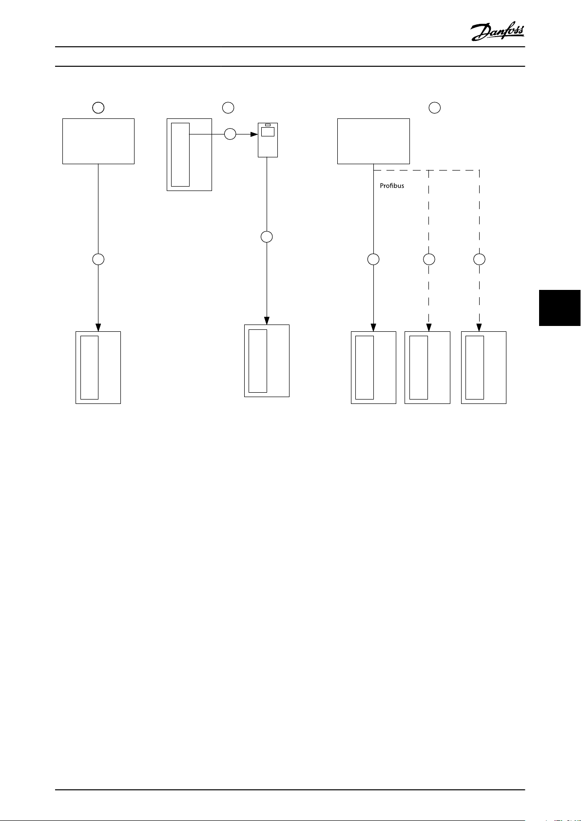
130BC327.10
FC302 1
FC302 1
FC302 1 FC302 2 FC302 3
FC302 2
MCT10
RS-485
MCB15x
MCB15x
MCB15x
MCB15x
MCB15x
MCB15x
MCT10
1 2 3
2
1
1
RS-485
USB
LCP
A
B C
Service and Repair Operating Instructions
7 7
Illustration 7.1 Possible Parameter Set-up
7.4
Commissioning Test
The commissioning test for systems with safety functions is
focused on validating the functionality of safety
monitoring and stop functions configured in the frequency
converter system.
The test objective is to verify proper configuration of the
defined safety functions and of test mechanisms and to
examine the response of specific monitoring functions to
the explicit input of values outside tolerance limits. Test
safety-configured monitoring functions running in the final
set-up.
Safety Guidelines
7.4.1
When commissioning/recommissioning, note the following
Secure the site in accordance with the regulations
•
(barrier, warning signs etc.). The system may only
be commissioned/recommissioned by qualified
7.4.2
personnel.
Refer to the information and specifications stated
•
in the operating instructions of the relevant
programmable control system.
During commissioning/recommissioning, make
•
sure that no personal injury and/or material
damage can occur, even if the plant/machine
moves unintentionally.
When commissioning the safety option, read the
•
safety guidelines in the Start up and Functional
Testing chapter in the operating instructions for
the frequency converter.
Condition before Performing the
Commissioning Test
The system integrator/machine manufacturer performs a
commissioning test of the safety option to verify and
document the correct selection of the safety option
parameter values. The system integrator/machine
MG34W302 Danfoss A/S © Rev. 2014-02-11 All rights reserved. 51
Page 54

Service and Repair Operating Instructions
manufacturer hereby proves to have tested the
effectiveness of the safety functions used. The commissioning test must be performed on the basis of the risk
analysis. All applicable standards and regulations must be
adhered to.
The machine is properly wired
•
Check the effectiveness of all safety components
•
used in the application
All safety equipment such as protective door
•
monitoring devices, light barriers or emergency
stop switches is connected and ready for
operation
All motor parameters and command parameters
•
must be set correctly on the frequency converter
A commissioning test of the safety option must be
performed in the following situations
77
After the configuration of each machine
•
After changing the safety option parameters
•
After making changes to the machine (as per
•
applicable standards and regulations)
Check the effectiveness of all safety functions used.
1. Document each individual step of the test.
2. Note the checksum of the safety option
parameters in the records.
3. Do NOT release the system unless it has
successfully passed all individual steps of the test.
4. Restart the frequency converter and check that
the motor runs normally.
52 Danfoss A/S © Rev. 2014-02-11 All rights reserved. MG34W302
Page 55

Service and Repair Operating Instructions
7.4.3 Safety Functions of the Frequency Converter
Commissioning test report
After making e.g. LCP copy of safe parameters a commissioning test is required. Use this short version of the commissioning
test report to follow and approve the test sequence.
Safety functions Test procedure
Safe Torque Off (STO)
1. Safe Torque Off function must be disabled
via DI1.
-
via DI2.
-
Check the Safe Torque Off circuit connections against the
-
circuit diagram.
2. No safety faults and alarms.
3. Run the frequency converter.
4. Ensure that the correct frequency converter is running.
5. Select Safe Torque Off while the frequency converter is running.
6. Check the following
The frequency converter coasts to zero speed.
-
The motor is braked and stopped by the mechanical brake
-
(if available and configured).
Warning/Alarm 68 is displayed.
-
7. Deselect Safe Torque Off.
8. Check the following
Depending on the configuration, Safety Func. Pending is
-
displayed.
Safe Torque Off deselected and inactive.
-
9. Restart the frequency converter and check that the motor runs
normally.
10. Ensure that the Safe Torque Off function is safe and accepted to
operate.
11. Document and sign the commissioning test report.
Approved ☑
7 7
Table 7.3 Commissioning Test Report, Safe Torque Off
MG34W302 Danfoss A/S © Rev. 2014-02-11 All rights reserved. 53
Page 56

Service and Repair Operating Instructions
Safety functions Test procedure
1. Safe Stop 1 function must be disabled
via DI1.
-
via DI2.
-
Check the Safe Stop 1 circuit connections against the circuit
-
diagram.
2. No safety faults and alarms.
3. Run the frequency converter.
4. Ensure that the correct frequency converter is running.
5. Select Safe Stop 1 while the frequency converter is running.
6. Check the following
The frequency converter ramps down to zero speed. Ensure
-
Safe Stop 1 time based (SS1)
77
7. Deselect Safe Stop 1.
8. Check the following
9. Restart the frequency converter and check that the motor runs
normally.
10. Ensure that the Safe Stop 1 function is ready to operate.
11. Document and sign the commissioning test report.
that it stops within the delay time specified.
The motor is braked and stopped by the mechanical brake
-
(if available and configured).
The SS1 will end with an STO warning or alarm, depending
-
on configuration.
Safety Func. Pending is displayed.
-
Safe Stop 1 deselected and inactive.
-
Approved ☑
Table 7.4 Commissioning Test Report, Safe Stop 1 Time Based
54 Danfoss A/S © Rev. 2014-02-11 All rights reserved. MG34W302
Page 57

Service and Repair Operating Instructions
Safety functions Test procedure
Safe Stop 1 Delay
1. Safe Stop 1 Delay function must be disabled
via DI1.
-
via DI2.
-
Check the Safe Stop 1 circuit connections against the circuit
-
diagram.
2. No safety faults and alarms.
3. Run the frequency converter.
4. Ensure that the correct frequency converter is running.
5. Select Safe Stop 1 Delay while the frequency converter is running.
6. Check the following
The frequency converter ramps down to zero speed. Ensure
-
that it stops within the delay time specified.
The motor is braked and stopped by the mechanical brake
-
(if available and configured).
The SS1 will end with an STO warning or alarm depending
-
on configuration.
7. Deselect Safe Stop 1 Delay.
8. Check the following
Safety Func. Pending is displayed.
-
Safe Stop 1 Delay deselected and inactive.
-
9. Restart the frequency converter and check that the motor runs
normally.
10. Ensure that the Safe Stop 1 function is ready to operate.
11. Document and sign the commissioning test report.
Approved ☑
7 7
Table 7.5 Commissioning Test Report, Safe Stop 1 Delay
MG34W302 Danfoss A/S © Rev. 2014-02-11 All rights reserved. 55
Page 58
Service and Repair Operating Instructions
Safety functions Test procedure
1. Safe Stop 1 function must be disabled
via DI1.
-
via DI2.
-
Check the Safe Stop 1 circuit connections against the circuit
-
diagram.
2. No safety faults and alarms.
3. Run the frequency converter.
4. Ensure that the correct frequency converter is running.
5. Select Safe Stop 1 while the frequency converter is running.
6. Check the following
The frequency converter ramps down to zero speed.
-
Safe Stop 1 ramp based (SS1)
77
7. Deselect Safe Stop 1.
8. Check the following
9. Restart the frequency converter and check that the motor runs
normally.
10. Ensure that the Safe Stop 1 function is ready to operate.
11. Document and sign the commissioning test report.
The motor is braked and stopped by the mechanical brake
-
(if available and configured).
The SS1 will end with an STO warning or alarm depending
-
on configuration.
Safety Func. Pending is displayed.
-
Safe Stop 1 deselected and inactive.
-
Approved ☑
Table 7.6 Commissioning Test Report, Safe Stop 1 Ramp Based
56 Danfoss A/S © Rev. 2014-02-11 All rights reserved. MG34W302
Page 59

Service and Repair
Operating Instructions
Safety functions Test procedure
Safely Limited Speed (SLS) without ramp
1. Safely Limited Speed function must be disabled
via DI1.
-
via DI2.
-
Check the Safely Limited Speed circuit connections against the circuit
diagram.
2. No safety faults and alarms.
3. Run the frequency converter.
Up and down ramps can be separately entered for JOG
-
operation (JOG-Mode). This can be parameterised as part of
the Quick Menu.
The motor speed must be higher than the Safely Limited
-
Speed selected, if the machine allows this
4. Ensure that the correct frequency converter is running.
5. Select Safely Limited Speed while the frequency converter is
running.
6. Check the following
The frequency converter coasts to zero speed if Safe Torque
-
Off is selected as fault reaction.
Run Safe Stop 1 if that is selected as fault reaction.
-
The motor is braked and stopped by the mechanical brake
-
(if available and configured).
Ensure that Error 70 is displayed.
-
7. Deselect Safely Limited Speed.
8. Check the following
Safety Func. Pending is displayed.
-
Safely Limited Speed deselected and inactive.
-
9. Restart the frequency converter and check that the motor runs
normally.
10. Ensure that the Safely Limited Speed function is ready to operate.
Run motor below SLS limit
-
Activate SLS
-
Increase reference above SLS limit
-
Make sure that SLS limit will not be exceeded
-
11. Document and sign the commissioning test report.
Approved ☑
7 7
Table 7.7 Commissioning Test Report, Safely Limited Speed without Ramp
MG34W302 Danfoss A/S © Rev. 2014-02-11 All rights reserved. 57
Page 60
Service and Repair Operating Instructions
Safety functions Test procedure
1. Safely Limited Speed function must be disabled
via DI1.
-
via DI2.
-
Check the Safely Limited Speed circuit connections against
-
the circuit diagram.
2. No safety faults and alarms.
3. Run the frequency converter.
The motor speed must be higher than the Safely Limited
-
Speed selected, if the machine allows this
4. Ensure that the correct frequency converter is running.
5. Select Safely Limited Speed while the frequency converter is
running.
6. Check the following
The speed ramps down according to the chosen ramp time/
-
77
7. Deselect Safely Limited Speed.
8. Safe Func. Pending is displayed.
Safely Limited Speed (SLS) with ramp
9. Run the frequency converter.
10. Ensure that the correct frequency converter is running.
11. Select Safely Limited Speed while the frequency converter is
running.
12. Check the following
13. Deselect Safely Limited Speed.
14. Check the following
15. Reset the frequency converter and check that the motor runs
normally.
16. Ensure that the Safely Limited Speed function is ready to operate.
17. Document and sign the commissioning test report.
slope to Safely Limited Speed set point.
The motor speed must be higher than the Safely Limited
-
Speed selected, if the machine allows this
The frequency converter ramps down to the Safe Limited
-
Speed.
No safety faults.
-
Safe Func. Pending is displayed.
-
Approved ☑
Table 7.8 Commissioning Test Report, Safely Limited Speed with Ramp
Tester/Approver
58 Danfoss A/S © Rev. 2014-02-11 All rights reserved. MG34W302
Date:
Signature:
Page 61

Service and Repair Operating Instructions
7.5 Disposal
Equipment containing electrical
components may not be disposed of
together with domestic waste.
It must be separately collected with
electrical and electronic waste according
to local and currently valid legislation.
7 7
MG34W302 Danfoss A/S © Rev. 2014-02-11 All rights reserved. 59
Page 62
Warnings and Alarms Operating Instructions
8 Warnings and Alarms
8.1 Fault Types and Messages
This chapter provides troubleshooting tables for diagnosing fault conditions associated with the safety option.
The safety option differentiates between the fault types shown in Table 8.1.
Fault type Description Effect on the system Reset condition
Fatal Error Severe exceptional error caused by the program run
in the safety option. Cyclic program sequence is no
longer possible for safety related reasons. The last
active function is displayed. The system is in stop
mode.
Alarm Functional fault, caused by an external process. Both
systems continue to run cyclically and serve all
requests from the communication interfaces. Sensing
of the external process is also maintained.
Output S37 is switched off Reset possible by power
cycling the frequency
converter or restart the safety
option via 42-90 Restart Safe
Option
Output S37 is switched off! Reset possible via parameter-
izable input DI2, reset on
LCP/DI or via Field bus or via
42-90 Restart Safe Option
88
Table 8.1 Fault Types
Colour Mode Description
Green Flashing System OK, configuration validated
Green Permanent System OK, input or output activated
Yellow Flashing System OK, configuration not yet validated
Red Flashing Alarm
Red Permanent Fatal error
Table 8.2 LED Status Indicators
All external failures can be removed by giving a reset
signal (via LCP, DI2a and digital inputs on control card or
via fieldbus depending on configuration). All internal
failures can be removed by power cycle, 42-90 Restart Safe
Option and configuration.
Messages
8.1.1
Any errors on the safety option are indicated on the
frequency converter display with different messages
The following options are available for detailed diagnostics
and fault detection
Status of the safety option input and output
•
errors, messages and the corresponding remedies
are displayed in the expanded diagnostics system
of MCT 10 Set-up Software.
LEDs on the front of the safety option provide
•
information on operating states. The LEDs are
used to indicate the status of the option, i.e.
active safety functions, failures and warnings, if
any.
LCP text or info via bus display the status of the
•
safety functions (e.g. SS1a).
The following are displayed in online mode in the MCT 10
Set-up Software
60 Danfoss A/S © Rev. 2014-02-11 All rights reserved. MG34W302
Page 63
Warnings and Alarms Operating Instructions
8.2 Warnings and Alarms
NOTICE
The errors are listed numerically.
Error
No. Description
Internal failure Reason Action
1 Diagnostic in
progress
67 Int Fail
tolerance error
exceeded:
Reaction STO
68 Int fail Speed
limit SS1a
Ramp: Reaction
STO
69 Int fail Speed
limit SS1b
Ramp: Reaction
STO
Green
Check that data for
•
feedback (ppr., type of
feedback and gear
ratio) are entered
correctly
Direction of feedback
•
is wrong
Due to use of
•
feedback filter the
dynamic of the system
does not match with
dynamic of feedback
filter (42-15 Feedback
Filter). System is
ramping too fast.
Feedback signals are
•
not received at all
No proper shielding of
•
feedback cables
The value of Delta V is
•
too small. For closed
loop system it must
often be larger than
the recommended
value.
Due to use of
•
feedback filter the
dynamic of the system
does not match with
dynamic of feedback
filter (42-15 Feedback
Filter).
Load change takes
•
place during ramping.
See 68 See 68 Red constant
LED1 LED 2 LED4
Make a re-customi-
•
sation with correct
data if needed
Set 42-12 Encoder
•
Direction to the
opposite value
Decrease ramping
•
time on frequency
converter
Try to run the
•
system at e.g. 60
RPM. If error nr. 99
now occurs, this is
the reason.
Improve shielding
•
of feedback cables
and motor cables.
If running in closed
•
loop, try to adjust
PID setting and if
needed increase
SS1 ramping time.
Try to increase
•
42-15 Feedback
Filter, but this
might cause error
nr. 67 to occur.
Otherwise increase
•
42-45 Delta V.
Led Indications
Green
constant
constant
Red constant
8 8
Status of LED 1 and LED2 depends on safety
function state assigned to DI1 and DI2
Red constant
MG34W302 Danfoss A/S © Rev. 2014-02-11 All rights reserved. 61
Page 64

Warnings and Alarms Operating Instructions
Error
No. Description
Internal failure Reason Action
70 Int fail speed
limit SLSa :
Reaction STO
71 Int fail speed
limit SLSb :
88
Reaction STO
72 Internal failure
MCB 150/151
73 Internal failure
MCB 150/151
Happens during ramping to
SLS limit, see 68.
Happens during speed below
SLS limit:
If speed is above cut-off
•
speed at activation point
and 42-53 Start Ramp is set
to “No”, this error occurs.
Noise on the feedback
•
signal (incl. quantisation
noise) is larger than
expected.
Load change takes place,
•
do as in above point)
See 70 See 70 Red constant
LED1 LED 2 LED4
Change 42-53 Start
•
Ramp to “Yes” and
set 42-54 Ramp Down
Time accordingly.
Increase 42-50 Cut Off
•
Speed or decrease
42-51 Speed Limit to
get a larger tolerance
First, power cycle the
•
frequency converter
or restart the safety
option by
42-90 Restart Safe
Option. Secondly, try
to make a general
reset of the safety
option with the
“Administration”
button (safety option
goes back to blank
initial state)
If the problem
•
persists, contact
Danfoss
First, power cycle the
•
frequency converter
or restart the safety
option by
42-90 Restart Safe
Option.
If the problem
•
persists, contact
Danfoss
Led Indications
Green
constant
Red constant
Red constant
Status of LED 1 and LED2 depends on
safety function state assigned to DI1
and DI2
Red constant
62 Danfoss A/S © Rev. 2014-02-11 All rights reserved. MG34W302
Page 65

Warnings and Alarms Operating Instructions
Error
No. Description
Internal failure Reason Action
74 Internal failure
MCB 150/151
75 Int Fail DI2 in
PUST: Reaction
STO
76 Int Fail DI1 in
PUST: Reaction
STO
77 Int Fail failsafe
data CRC
mismatch:
Reaction STO
Safety input connected
•
to DI2 has illegal
signal level.
Sensor is broken
•
Safety input connected
•
to DI1 has illegal
signal level.
Sensor is broken
•
The CRC of the safety
option does not match
the stored CRC value on
the frequency converter.
LED1 LED 2 LED4
First, power cycle
•
the frequency
converter or restart
the option by
42-90 Restart Safe
Option.
If the problem
•
persists, contact
Danfoss
Check that configu-
•
ration of DI2
42-21 Type
parameter is set
correctly or that
the connected
sensor is installed
according to
specification.
Extend discrepancy
•
time on safe input
tab in MCT 10 safe
plug-in
14-22 Operation
Mode.
Check that the
•
configuration of
DI1 (42-21 Type sub
index [0] is set
correctly or the
connected sensor
is installed
according to
specification.
Extend discrepancy
•
time on safe input
tab in MCT 10 safe
plug-in
14-22 Operation
Mode.
Configure the safety
option with MCT 10
safe plug-in or by CRC
select/LCP copy
Led Indications
Green
constant
Red constant
Red constant
8 8
Status of LED 1 and LED2 depends on safety
function state assigned to DI1 and DI2
Red constant
Red constant
MG34W302 Danfoss A/S © Rev. 2014-02-11 All rights reserved. 63
Page 66

Warnings and Alarms Operating Instructions
Error
No. Description
Internal failure Reason Action
78 Internal failure
safety option
79 Internal failure
safety option
80 Internal failure
safety option
81 Internal failure
safety option
Contact Danfoss Red constant
Contact Danfoss Red constant
88
82 Internal failure
safety option
83 Internal failure
safety option
84 Internal failure
safety option
85 Internal failure
safety option
LED1 LED 2 LED4
First, power cycle
•
the frequency
converter or restart
the safety option
by 42-90 Restart
Safe Option.
If the problem
•
perists, contact
Danfoss
First, power cycle
•
the frequency
converter.
If the problem
•
persists, contact
Danfoss
First, power cycle
•
the frequency
converter.
If the problem
•
persists, contact
Danfoss
First, power cycle
•
the frequency
converter.
If the problem
•
persists, contact
Danfoss
First, power cycle
•
the frequency
converter.
If the problem
•
persists, contact
Danfoss
First, power cycle
•
the frequency
converter.
If the problem
•
persists, contact
Danfoss
Led Indications
Green
constant
Red constant
Red constant
Red constant
Status of LED 1 and LED2 depends on safety
function state assigned to DI1 and DI2
Red constant
Red constant
Red constant
64 Danfoss A/S © Rev. 2014-02-11 All rights reserved. MG34W302
Page 67

Warnings and Alarms Operating Instructions
Error
No. Description
Internal failure Reason Action
86 Internal failure
safety option
87 Internal failure
safety option
88 Internal failure
safety option
89 Internal failure
safety option
90 Internal failure
safety option
91 Internal failure
safety option
92 Internal failure
safety option
LED1 LED 2 LED4
First, power cycle
•
the frequency
converter.
If the problem
•
persists, contact
Danfoss
First, power cycle
•
the frequency
converter.
If the problem
•
persists, contact
Danfoss
First, power cycle
•
the frequency
converter.
If the problem
•
persists, contact
Danfoss
Perform a general
•
reset of the safety
option with the
“Administration”
button.
If the problem
•
persists, contact
Danfoss
Perform a general
•
reset of the safety
option with the
“Administration”
button.
If the problem
•
persists, contact
Danfoss
First, power cycle
•
the frequency
converter.
If the problem
•
persists, contact
Danfoss
First, power cycle
•
the frequency
converter.
If the problem
•
persists, contact
Danfoss
Led Indications
Green
constant
Red constant
Red constant
Red constant
8 8
Red constant
Status of LED 1 and LED2 depends on safety
function state assigned to DI1 and DI2
Red constant
Red constant
Red constant
MG34W302 Danfoss A/S © Rev. 2014-02-11 All rights reserved. 65
Page 68

Warnings and Alarms Operating Instructions
Error
No. Description
Internal failure Reason Action
93 Internal failure
safety option
94 Internal failure
safety option
95 Internal failure
safety option
88
96 Internal failure
safety option
97 Internal failure
safety option
98 Int fail invalid
customer file
version
99 Int Fail
Feedback error
113 Ext Fail DI1 :
Reaction STO
Version of customisation
file of safety option stored
in EEPROM does not
match the customisation
file supported by the SW
version of safety option.
The connected feedback
source does not give any
signal.
Safety input connected
•
to DI1 has illegal
signal level.
Sensor is broken.
•
LED1 LED 2 LED4
First, power cycle
•
the frequency
converter.
If the problem
•
persists, contact
Danfoss
First, power cycle
•
the frequency
converter.
If the problem
•
persists, contact
Danfoss
First, power cycle
•
the frequency
converter.
If the problem
•
persists, contact
Danfoss
First, power cycle
•
the frequency
converter.
If the problem
•
persists, contact
Danfoss
Contact Danfoss Red constant
•
Do a new configuration with MCT 10
safe plug-in which
supports the SW
version of safety
option.
Check the connection
is done according to
the specification or if
the feedback source is
broken.
Check that configu-
•
ration of DI1
42-21 Type
parameter is set
correctly or the
connected sensor
is installed
according to
specification
Led Indications
Status of LED 1 and LED2 depends on safety
function state assigned to DI1 and DI2
Red Constant
Status depends on
safety function state
assigned to DI2
Green
constant
Red constant
Red constant
Red constant
Red constant
Red
Red flashing,
cycle (on 500
ms, off 500
ms)
66 Danfoss A/S © Rev. 2014-02-11 All rights reserved. MG34W302
Page 69

Warnings and Alarms Operating Instructions
Error
No. Description
114 Ext Fail DI2 :
Reaction STO
115 Ext Fail Prec
Thresh Timer
Elapsed :
Reaction STO
116 Ext Fail SF
activation
Speed
Suspension :
Reaction STO
134 Int fail speed
limit SLSa:
Reaction SS1a
135 Int fail speed
limit
SLSb :Reaction
SS1a
177 Ext Fail
DI1 :Reaction
SS1a
178 Ext Fail
DI2 :Reaction
SS1a
Led Indications
LED1 LED 2 LED4
Safety input connected
•
to DI2 has illegal
signal level.
Sensor is broken
•
The frequency converter
has been running below
120 RPM for more than
the time entered in
parameter 42-18 Zero
Speed Timer with safe
function SLS active.
The frequency converter
has been running below
120 RPM for more that 1
year and a safety function
that need speed feedback
is activated.
See 70 See 70
See 70 See 70 Red constant
See 113 See 113 Red constant Status depends on
See 114 See 114 Status depends on
Check that configu-
•
ration of DI2
42-21 Type
parameter is set
correctly or the
connected sensor
is installed
according to
specification
Extend discrepancy
•
time on safe input
tab in MCT 10 safe
plug-in
14-22 Operation
Mode.
Increase speed to
above 120 RPM.
Increase speed to
above 120 RPM.
Status depends on
safety function state
assigned to DI1
Status of LED 1 and LED2 depends on Safety
function state assigned to DI1 and DI2
Status of LED 1 and LED2 depends on safety
function state assigned to DI1 and DI2
Safety function state
assigned to DI1
Red constant Red flashing,
safety function state
assigned to DI2
Red constant Red flashing,
cycle (on 500
ms, off 500
ms)
Red flashing,
cycle (on 500
ms, off 500
ms)
Red flashing,
cycle (on 500
ms, off 500
ms)
Red constant
Red flashing,
cycle (on 500
ms, off 500
ms)
cycle (on 500
ms, off 500
ms)
8 8
MG34W302 Danfoss A/S © Rev. 2014-02-11 All rights reserved. 67
Page 70

Warnings and Alarms Operating Instructions
Error
No. Description
179 Ext Fail Prec
Thresh Timer
Elapsed
:Reaction SS1a
180 Ext Fail SF
activation
Speed
Suspension:
Reaction SS1a
198 Int fail speed
limit
SLSa :Reaction
SS1b
199 Int fail speed
limit
SLSb :Reaction
SS1b
241 Ext Fail
DI1 :Reaction
88
SS1b
242 Ext Fail
DI2 :Reaction
SS1b
243 Ext Fail Prec
Thresh Timer
Elapsed
:Reaction SS1b
244 Ext Fail SF
activation
Speed
Suspension
:Reaction SS1b
252 Internal failure
safety option
See 115 See 115
See 116 See 116 Red flashing,
See 70 See 70 Red constant
See 70 See 70 Red constant
See 113 See 113 Red constant Status depends on
See 114 See 114 Status depends on
See 115 See 115
See 116 See 116 Red flashing,
Power cycle the
LED1 LED 2 LED4
frequency converter. If
the problem persists,
contact Danfoss
Led Indications
Status of LED 1 and LED2 depends on safety
function state assigned to DI1 and DI2
safety function state
assigned to DI2
Red constant Red flashing,
Safety function state
assigned to DI1
Status of LED 1 and LED2 depends on Safety
function state assigned to DI1 and DI2
Red flashing,
cycle (on 500
ms, off 500
ms)
cycle (on 500
ms, off 500
ms)
Red flashing,
cycle (on 500
ms, off 500
ms)
cycle (on 500
ms, off 500
ms)
Red flashing,
cycle (on 500
ms, off 500
ms)
cycle (on 500
ms, off 500
ms)
8.2.1 Safety Option Warning
Safety option warning messages
A warning message notifies that an issue exists on the
safety option. It is not handled as an internal or external
failure. These messages are defined to indicate that a
manual user action is required.
NOTICE
8.2.2 Safety Option Reset Message
Requests for safety option RESET
For some messages, the safety option requires an acknowledgement of an ongoing action or failure on the safety
option.
The safety option uses 'Safe Option RESET' as a ‘Restart
and Failure Acknowledgement‘
At any possible failure or warning indicated from the
safety option, the LCP displays Warning ‘!Safe Option
Failure [W252]’ at the least.
68 Danfoss A/S © Rev. 2014-02-11 All rights reserved. MG34W302
Page 71

130BD126.10
Status
SO Reset required!
!1(1)
0 RPM None 0.00KW
!Safe Stop [W68]
130BD127.10
Status
SO in Self-test
!1(1)
0 RPM None 0.00KW
!Safe Stop [W68]
130BD128.10
Status
SF pending
!1(1)
0 RPM None 0.00KW
!Safe Stop [W68]
130BD129.10
Status
SafeOpt. initialised
!1(1)
0 RPM None 0.00KW
!Safe Stop [W68]
130BD130.10
Status
SO General Reset
!1(1)
0 RPM None 0.00KW
!Safe Stop [W68]
130BD131.10
Status
SO Suspend-SpeedMon
!1(1)
0 RPM None 0.00KW
!Safe Stop [W68]
130BD132.10
Status
SO Warning PUST
!1(1)
0 RPM None 0.00KW
!Safe Stop [W68]
130BD133.10
Status
SO Warning DI1
!1(1)
0 RPM None 0.00KW
!Safe Stop [W68]
130BD134.10
Status
SO Warning DI2
!1(1)
0 RPM None 0.00KW
!Safe Stop [W68]
130BD131.10
Status
SO Suspend-SpeedMon
!1(1)
0 RPM None 0.00KW
!Safe Stop [W68]
Warnings and Alarms
Operating Instructions
LCP message Description
In the following cases, the
safety option requests a
restart and failure acknowledgement-signal:
1. The safety option is in
safety function pendingstate (Remark: Occurs only
if reset behaviour is set/
configured to ‘manual’)
2. After a power cycle with a
safety function
3. In PUST (power up self
test), if an external failure
occurred before power
cycle
4. When an external failure
occurred
5. When customisation was
aborted or completed
6. At the reception of a
general reset (required
after blank initial state or
in the customisation
state.)
The safety option indicates
that it is PUST State (Power
Up Self Test).
1. Ensure that no safe
function is active after a
power cycle.
A safety function is pending
at the start-up, if the
frequency converter was
powered down while a safety
function was active.
It is also pending, when the
frequency converter was
powered down while the
safety option has detected a
failure during an active safety
function.
The safety option requests a
‘Restart and Failure
Acknowledge signal’, which is
always required after a PUST
and when a safety function
gets released and is
configured to be confirmed
that the motor is able to run.
LCP message Description
Occurs only if general reset is
performed from MCT 10. It is
an indication to the user. The
safety option is set to blank
initial state and safe
parameters are set to default.
Zero speed timer contains
the remaining time until the
fail prec thresh timer elapsed
after the monitoring time
expires. The safety option
signals Warning.
PUST warning has occurred.
Warning cause: Expiry of
PUST timer. Memory test
required, perform power
cycle.
8 8
DI1 offline warning has
occurred.
Warning cause: Expiry of
offline timer for DI1.
DI2 offline warning has
occurred.
Warning cause: Expiry of
offline timer for DI2.
Speed monitoring suspension
warning has occurred.
Warning cause: Suspension of
speed monitoring for certain
duration.
Table 8.3 LCP Messages
MG34W302 Danfoss A/S © Rev. 2014-02-11 All rights reserved. 69
Page 72

Technical Specifications Operating Instructions
9 Technical Specifications
9.1 Consumption
Safety option
Power consumption 2 W (equivalent power consumption related to VDD)
Current consumption VCC (5 V) < 200 mA
Current consumption VDD (24 V) < 30 mA (< 25 mA for MCB 150)
9.2 Inputs
Digital inputs
Number of digital inputs 4 (2 x 2-channel Digital Safety Input)
Input voltage range 0 to 24 V DC
Input voltage, logic '0' < 5 V DC
Input voltage, logic '1' > 12 V DC
Input voltage (max) 28 V DC
Input current (min) 6 mA @Vin=24 V (inrush current 12 mA peak)
Input resistance approx. 4 kΩ
Galvanic isolation No
Short circuit-proof Yes
Input pulse recognition time (min) 3 ms
99
Discrepancy time (min) 9 ms
< 30 m (screened or unscreened cable)
Cable length
> 30 m (screened cable)
TTL encoder input (MCB 150)
Number of encoder inputs 4 (2 x differential inputs A,/A; B,/B)
Encoder types TTL, RS-422/RS-485 incremental encoders
Input differential voltage range -7 to +12 V DC
Input common mode voltage -12 to +12 V DC
Input voltage, logic '0' (diff) < -200 mV DC
Input voltage, logic '1' (diff) > +200 mV DC
Input resistance approx. 120 Ω
Maximum frequency 410 KHz
Short circuit-proof Yes
< 150 m (Tested with screened cable - Heidenhain AWM Style 20963 80°C 30V E63216, 100 m screened
Cable length
HTL encoder input (MCB 151)
Number of encoder inputs 2 (2 x single ended inputs A; B)
Encoder types HTL incremental encoders; HTL Proximity sensor
Logic input PNP
Input voltage range 0 to 24 V DC
Input voltage, logic '0' < 5V DC
Input voltage, logic '1' > 12 V DC
Input voltage (max) 28 V DC
Input resistance approx. 4 Ω
Maximum frequency 110 kHz
Short circuit-proof Yes
< 100 m (Tested with screened cable - Heidenhain AWM Style 20963 80°C 30V E63216, 100 m screened
Cable length
motor cable, no load on motor)
motor cable, no load on motor)
70 Danfoss A/S © Rev. 2014-02-11 All rights reserved. MG34W302
Page 73

Technical Specifications Operating Instructions
9.3 Outputs
Digital output (Safe output)
Number of outputs 1
Output voltage low < 2 V DC
Output voltage high > 19.5 V DC
Output voltage (max) 24.5 V DC
Nominal output current (@24 V) < 100 mA
Nominal output current (@0 V) < 0.5 mA
Galvanic Isolation No
Diagnostic test pulse 300 us
Short circuit-proof Yes
Cable length < 30 m (screened cable)
24 V supply output
Supply voltage 24 V DC (Voltage tolerance: +0.5 V DC to -4.5 V DC)
Maximum output current 150 mA
Short circuit-proof Yes
< 30 m (screened or unscreened cable)
Cable length
> 30 m (screened cable)
9.4 Other Specifications
Ground I/O section
< 30 m (screened or unscreened cable)
Cable length
Cable cross-sections
Digital inputs/output supply voltage 0.75 mm2/AWG 18, AEH without plastic collar in accordance with DIN 46228/1
Reset characteristics
Manual reset time
Manual reset pulse time 10 µs (safety option and frequency converter)
Automatic reset time ≤ 4 ms
Start-up reset time ≤ 5 s (42-90 Restart Safe Option)
Response time
Input to output response time ≤ 2 ms
Emergency stop until beginning of SS1/SLS ≤ 7 ms
Cross fault detection time ≤ 3 ms (@activated output)
> 30 m (screened cable)
≤ 5 ms (safety option)
≤ 5 ms (frequency converter)
≤ 10 ms (fieldbus)
9 9
MG34W302 Danfoss A/S © Rev. 2014-02-11 All rights reserved. 71
Page 74
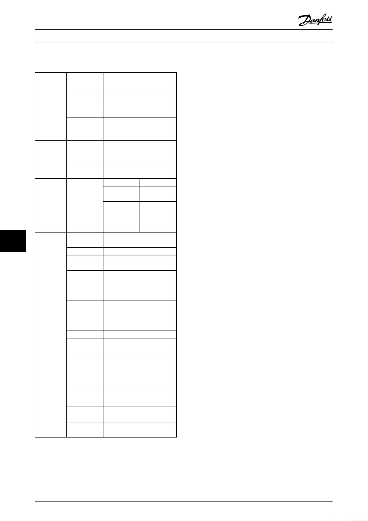
Technical Specifications
9.5 Safety Characteristic Data
Operating Instructions
Machinery
Directive
(2006/42/EC)
European
directives
Safety
standards
Safety
function
99
Safety
performance
EMC Directive
(2004/108/EC)
Low Voltage
Directive
(2006/95/EC)
Safety of
Machinery
Functional
Safety
Safety Integrity
Level
HFT (IEC 61508) Hardware Fault Tolerance = 1
Subsystem
Classification Type B
Probability of
Dangerous
Failure per
Hour PFH: 1,52 e-8
Probability of
Dangerous
Failure on
Demand PFD: 1,33 e-3
Category Cat 3
Performance
Level PL d (cat 3)
Mean Time to
Dangerous
Failure of each
Channel MTTFd: 245 years (High)
Average
Diagnostic
Coverage
Safe Failure
Fraction SFF: 90%
Proof Test
Interval 20 Years
EN ISO 13849-1
EN IEC 62061
EN IEC 61800-5-2
EN 50011
EN 61000-6-3
EN 61800-3
EN 50178
EN 61800-5-1
EN ISO 13849-1
IEC 62061
IEC 60204-1
IEC 61508-1 to -7
IEC 61800-5-2
IEC 61800-5-2 IEC 60204-1
Safe Torque Off
(STO)
Safe Stop 1
(SS1)
Safely Limited
Speed (SLS)
SIL 2
SIL CL2
DC
: 86% (Low)
ave
Stop Category
0
Stop Category
1
Table 9.1 Safety Characteristic Data
The safety-related characteristic data are valid for all safety
functions.
All units used within a safety function must be considered
when calculating the safety characteristic data.
72 Danfoss A/S © Rev. 2014-02-11 All rights reserved. MG34W302
Page 75

Index Operating Instructions
Index
A
Approval..................................................................................................... 9
B
Braking ramp....................................................... 13, 16, 17, 20, 24, 36
C
Cable length.................................................................................... 27, 30
Category 0 stop.............................................................................. 14, 15
Category 1 stop.............................................................................. 14, 15
Commissioning software................................................................... 36
Commissioning test........................................................ 24, 36, 37, 47
Configuration............................... 5, 9, 13, 16, 34, 35, 36, 46, 47, 60
Cross-section.......................................................................................... 30
D
Digital input........................................... 13, 14, 19, 20, 21, 22, 31, 60
Discrepancy................................................................................. 6, 22, 42
Disposal................................................................................................ 0
E
Encoder............................................... 6, 14, 17, 18, 21, 27, 30, 35, 36
Error response................................................................................. 19, 21
F
Feedback source............................................................................ 34, 66
H
HTL encoder............................................................................. 10, 14, 30
M
MCT 10 Safe Plug-in................................... 15, 33, 35, 36, 47, 63, 66
R
Ramp........................................................ 12, 16, 17, 19, 20, 24, 43, 44
Reset... 6, 13, 21, 22, 24, 33, 37, 38, 42, 47, 49, 50, 58, 60, 62, 68,
69, 71
Response time....................................................................................... 23
Risk assessment................................................................................ 8, 11
RS-485.................................................................................. 30, 33, 36, 47
S
Safe jog..................................................................................................... 20
Safe motion monitoring..................................................................... 13
Safe Stop 1........................... 7, 10, 12, 13, 14, 15, 16, 17, 19, 21, 36
Safe Torque Off......... 10, 12, 14, 15, 16, 17, 21, 22, 23, 24, 33, 36
Safely Limited Speed..................... 7, 12, 13, 14, 15, 18, 20, 21, 36
Safety control system................................................................... 10, 12
Safety function.... 7, 11, 12, 13, 14, 15, 16, 17, 18, 19, 21, 22, 23,
24, 33, 36
Safety sensor................................................................................... 13, 22
Sensor.................................................................. 6, 8, 10, 14, 21, 22, 31
Signal......... 9, 10, 14, 15, 17, 21, 22, 23, 24, 25, 27, 30, 35, 36, 60
SLS............................................................... 7, 13, 18, 20, 21, 41, 44, 67
S-ramp............................................................................................... 16, 43
SS1.............................................................................................................. 21
SS1 delay........................................................................................... 15, 16
SS1 ramp...................................................................... 15, 17, 19, 21, 61
Status indicator.............................................................................. 13, 60
STO................................................................................... 7, 14, 19, 21, 23
Supply voltage.......................... 9, 13, 23, 25, 27, 30, 33, 34, 46, 71
T
Technical specifications..................................................................... 70
Test pulse pattern.......................................................................... 23, 42
TTL encoder..................................................................................... 10, 30
O
Option change....................................................................................... 47
P
Password.................................................................................................. 47
PFD definition........................................................................................ 13
PFH definition........................................................................................ 13
PNP proximity switch.......................................................................... 31
PNP proximity Switch................................................................... 14, 24
Priority...................................................................................................... 12
MG34W302 Danfoss A/S © Rev. 2014-02-11 All rights reserved. 73
U
USB............................................................................................... 33, 36, 47
W
Warnings and alarms........................................................................... 60
Warranty.............................................................................................. 8, 46
Page 76
www.danfoss.com/drives
Danfoss can accept no responsibility for possible errors in catalogues, brochures and other printed material. Danfoss reserves the right to alter its products without notice. This also applies to
products already on order provided that such alterations can be made without subsequential changes being necessary in specifications already agreed. All trademarks in this material are property
of the respective companies. Danfoss and the Danfoss logotype are trademarks of Danfoss A/S. All rights reserved.
130R0292 MG34W302 Rev. 2014-02-11
*MG34W302*
 Loading...