

Page 1
Operating Instructions
VLT® 5000 Crane
Page 2

■ Contents
VLT® 5000 Crane
Introduction
Safety ....................................................................................................................... 4
General Instructions ................................................................................................. 5
Abbreviations and Definitions .................................................................................... 6
Brief Product Description .......................................................................................... 9
Function and System Description ............................................................................. 9
Key Diagram for VLT 5000 Crane 5042, 5102 400-500 V ....................................... 14
Key Diagram for VLT 5000 Crane 5122-5202 400-500 V ....................................... 15
......................................................................................................... 3
Technical Data .................................................................................................. 16
General Technical Data ........................................................................................... 16
Mains Supply 400 - 500 V ...................................................................................... 20
Mains supply 3 x 400 - 500 V ................................................................................. 20
Fuses ..................................................................................................................... 22
Mechanical Dimensions .......................................................................................... 23
Installation ......................................................................................................... 24
General Warning before Installation ........................................................................ 24
Mechanical Installation ........................................................................................... 24
Installation of VLT 5042–5062 400-500 V Compact IP20/IP00 ............................... 24
Installation of VLT 5072-5202 400-500 V Compact IP20/IP00 ................................ 25
Electrical Installation ............................................................................................... 26
RFI switch .............................................................................................................. 33
LCP - Local Control Panel .......................................................................... 36
Control Panel ......................................................................................................... 36
Display ................................................................................................................... 37
Parameter programming ........................................................................................ 39
Programming .................................................................................................... 42
General Advice on Programming ............................................................................ 42
Operation & Display ................................................................................................ 50
Load and Motor ..................................................................................................... 54
References & Limits ................................................................................................ 58
Inputs & Outputs .................................................................................................... 61
Application Functions ............................................................................................. 68
Service Functions ................................................................................................... 70
Crane Functions ..................................................................................................... 74
Serial communication .................................................................................. 80
Factory Settings ..................................................................................................... 81
Defined Parameters ................................................................................................ 85
All About VLT 5000 Crane .......................................................................... 86
Status Messages .................................................................................................... 86
List of Warnings and Alarms ................................................................................... 87
Warnings ................................................................................................................ 87
MG.50.N4.02 - VLT is a registered Danfoss trademark
1
Page 3

VLT® 5000 Crane
Appendix ............................................................................................................. 92
Trouble-shooting .................................................................................................... 92
Derating for air pressure ......................................................................................... 94
Efficiency .............................................................................................................. 113
General aspects of EMC emissions ...................................................................... 114
2
MG.50.N4.02 - VLT is a registered Danfoss trademark
Page 4
VLT® 5000 Crane
VLT 5000 Crane
175ZA522.12
Operating instructions
Software version: 20.3x
These operating instructions can be used for VLT 5000
Crane frequency converters with software version 20.3x.
See software version number in parameter 624.
Introduction
MG.50.N4.02 - VLT is a registered Danfoss trademark
3
Page 5
VLT® 5000 Crane
■Safety
The voltage of the frequency converter
is dangerous whenever the equipment is
connected to mains. Incorrect installation
of the motor or the frequency converter may cause
damage to the equipment, serious personal injury
or death. Consequently, the instructions in this
manual, as well as national and local rules and safety
regulations, must be complied with
■Safety Regulations
1. The frequency converter must be disconnected
from mains if repair work is to be carried out. Check
that the mains supply has been disconnected
and that the necessary time has passed before
removing motor and mains plugs.
2. The [STOP/RESET] key on the control panel of
the frequency converter does n
the equipment from mains and is thus n
be used as a safety switch.
3. Correct protective earthing of the equipment
must be established, the user must be protected
against supply voltage, and the motor must be
protected against overload in accordance with
applicable national and local regulations.
4. The earth leakage currents are higher than 3.5 mA.
5. Protection against motor overload is n
in the factory setting. If this function is desired,
set parameter 128 to data value ETR trip or
data value ETR warning.
N
ote: The function is initialised at 1.16 x rated
motor current and rated motor frequency. For
the North American market: The ETR function
ot disconnect
ot to
ot included
provide class 20 motor overload protection
in accordance with NEC.
6. Do n
7. Please note that the frequency converter has more
■Warning Against Unintended Start
1. The motor can be brought to a stop by means
2. While parameters are being changed, the
3. A motor that has been stopped may start if faults
4. Immediate stop. Direct stop input (term. 37). When
s
ot remove the plugs for the motor and mains
supply while the frequency converter is connected
to mains. Check that the mains supply has been
disconnected and that the necessary time has
passed before removing motor and mains plugs.
voltage inputs than L1, L2 and L3, when loadsharing
terminals (linking of DC intermediate circuit) and
external 24 V DC have been installed. Check
that all voltage inputs have been disconnected
and that the necessary time has passed before
repair work is commenced.
of digital commands, bus commands, references
or a local stop, while the frequency converter
is connected to mains. If personal safety
considerations make it necessary to ensure
that no unintended start occurs, these stop
functions are not sufficient.
motor may start. Consequently, the stop key
[STOP/RESET] must always be activated, following
which data can be modified.
occur in the electronics of the frequency converter,
or if a temporary overload or a fault in the supply
mains or the motor connection ceases.
contact is open, the drive will stop (coast).
Warning:
Touching the electrical parts may be fatal - even after the
equipment has been disconnected from mains.
Also make sure that other voltage inputs have been
disconnected, such as external 24 V DC, load-sharing (linkage of
DC intermediate circuit), as well as the motor connection for
kinetic back-up.
Using VLT 5042-5062: wait at least 15 minutes.
Using VLT 5072-5202: wait at least 20 minutes.
175ZA523.11
4
MG.50.N4.02 - VLT is a registered Danfoss trademark
Page 6
VLT® 5000 Crane
■General Instructions
These Operating Instructions are intended for
persons who are to install, operate and program
the VLT 5000 Crane.
They comprise the specific technical publications on
the VLT 5000 Crane and are delivered with the product.
When reading these Operating Instructions you come across different symbols that require special attention:
The symbols used are the following:
Indicates a general warning
Indicates a high-voltage warning
NB!:
Indicates something to be noted by the reader
Introduction
MG.50.N4.02 - VLT is a registered Danfoss trademark
5
Page 7
■Abbreviations and Definitions
■Frequency converter
Abbreviation/Definition Description
I
VLT,MAX
I
VLT,N
U
VLT,MAX
■Output
Abbreviation/Definition Description
I
M
U
M
f
M
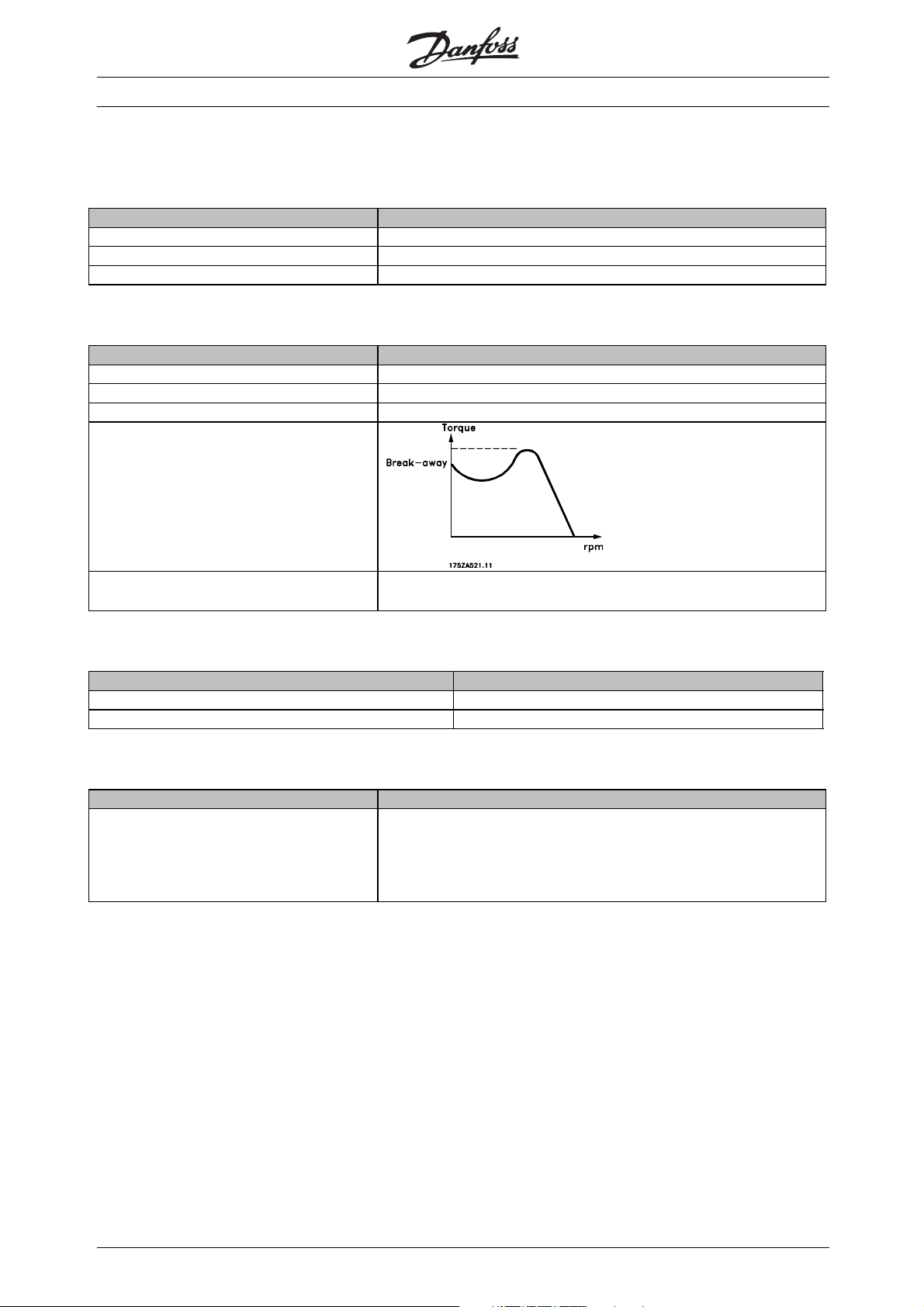
Break-away torque
VLT® 5000 Crane
The maximum output current
The rated output current supplied by the frequency converter
The maximum output voltage
The current transmitted to the motor
The voltage transmitted to the motor
The frequency transmitted to the motor
η
VLT
The efficiency of the frequency converter is defined as the ratio between the
power output and power input
■NO/NC
Abbreviation/Definition Description
NO Normally open
NC Normally closed
■Input
Abbreviation/Definition Description
Control command
Immediate stop
Stop command
By means of LCP and the digital inputs, it is possible to start and stop the
connected motor.
6
MG.50.N4.02 - VLT is a registered Danfoss trademark
Page 8

■Motor
I
M,N
f
M,N
U
M,N
P
M,N
n
M,N
T
M,N
■References
VLT® 5000 Crane
Abbreviation/Definition Description
The rated motor current (nameplate data)
The rated motor frequency (nameplate data)
The rated motor voltage (nameplate data)
The rated power delivered by the motor (nameplate data)
The rated motor speed (nameplate data)
The rated torque (motor)
Abbreviation/Definition Description
Analogue ref. A signal transmitted to input 53, 54 or 60. Can be voltage or current
Binary ref. A signal transmitted to the serial communication port
Ref
MAX
The maximum value which the reference signal may have. Set in parameter 205
■Miscellaneous
Abbreviation/Definition Description
ELCB Earth Leakage Circuit Breaker
Trip A state which occurs in different situations, eg. if the frequency converter is subject to a live zero warning.
A trip can be cancelled by pressing Reset
Trip locked A state which occurs in different situations, eg. if the frequency converter is subject to an overtemperature.
A locked trip can be cancelled by cutting off mains and restarting the frequency converter and pressing
Reset
Initializing If initializing is carried out (see parameter 620), the frequency converter returns to the factory setting
LCP The Local Control Panel, which makes up a complete interface for control and programming of VLT 5000
Crane. The control panel is detachable and may, as an alternative, be installed up to 3 metres away from
the frequency converter, ie. in a front panel, by means of the installation kit option
Flux Vector If compared with standard voltage/frequency ratio control, Flux Vector improves the dynamics and the
stability, both when the speed reference is changed and in relation to the load torque
Thermistor A temperature-dependent resistor placed where the temperature is to be monitored (frequency converter
or motor)
Analogue inputs The analogue inputs can be used for controlling various functions of the frequency converter. There are
two types of analogue inputs:
Current input and voltage input
Analogue outputs There are two analogue current outputs
Digital inputs The digital inputs can be used for controlling various functions of the frequency converter
Digital outputs There are four digital outputs, two of which activate relay switches.
Brake resistor The brake resistor is a module capable of absorbing the brake power that is generated in regenerative
braking. This regenerative braking power increases the intermediate circuit voltage and a brake chopper
ensures that the power is transmitted to the brake resistor
Incremental encoder An external, digital pulse transmitter used for feeding back information on motor speed. The encoder is
used in applications where high accuracy in speed control is required
AWG Means American Wire Gauge, ie. the American measuring unit for cable cross-section
Introduction
MG.50.N4.02 - VLT is a registered Danfoss trademark
7
Page 9
VLT® 5000 Crane
■Miscellaneous- continued
Abbreviations/Definitions Description
Manual initialisation Press the [CHANGE DATA] + [MENU] + [OK] keys at the same time to carry out
manual initialisation. See also Parameter 620.
Note that manual initialisation is only to be used if the reset function does not work!
SFAVM Switching pattern called Stator Flux oriented Asynchronous Vector Modulation
On-line/off-line parameters On-line parameters are activated immediately after the data value is changed.
Off-line parameters are not activated until OK has been entered on the control unit
CT characteristics Constant torque characteristics, used for all applications, such as conveyor belt
and cranes.
MCM Stands for Mille Circular Mil, an American measuring unit for cable cross-section
1 MCM=0.5067mm
ETR Electronic thermal relay is a thermal load calculation based on present load and
time. Its purpose is to estimate the motor temperature
CP Constant power
2
s
8
MG.50.N4.02 - VLT is a registered Danfoss trademark
Page 10

■Brief Product Description
The VLT 5000 Crane frequency converter supplies
a motor with variable voltage and frequency and
thereby enables infinitely variable speed control of
three-phased standard AC-motors.
The VLT 5000 Crane features the Flux Vector
control system.
The VLT 5000 Crane uses a digital technique
making it possible to program the different control
inputs and signal outputs.
The user can easily program the desired functions
by means of the VLT 5000 Crane control panel or
the user interfaces RS485 and RS232.
The VLT 5000 Crane is protected against the transients
occurring in the mains supply. Furthermore, a
good power factor and low peak current, reducing
the load on the mains installation, are ensured
through intermediate circuit coils.
Current measurement on all three motor phases
perfectly protects VLT 5000 Crane against earthing and
short-circuiting faults on the motor connenction.
VLT® 5000 Crane
Introduction
VLT 5000 Crane offers:
• Full utilisation of control range
• 130% torque for acceleration
• Fine adjustment at standstill + full load possible
without activating the system brake
■System Description
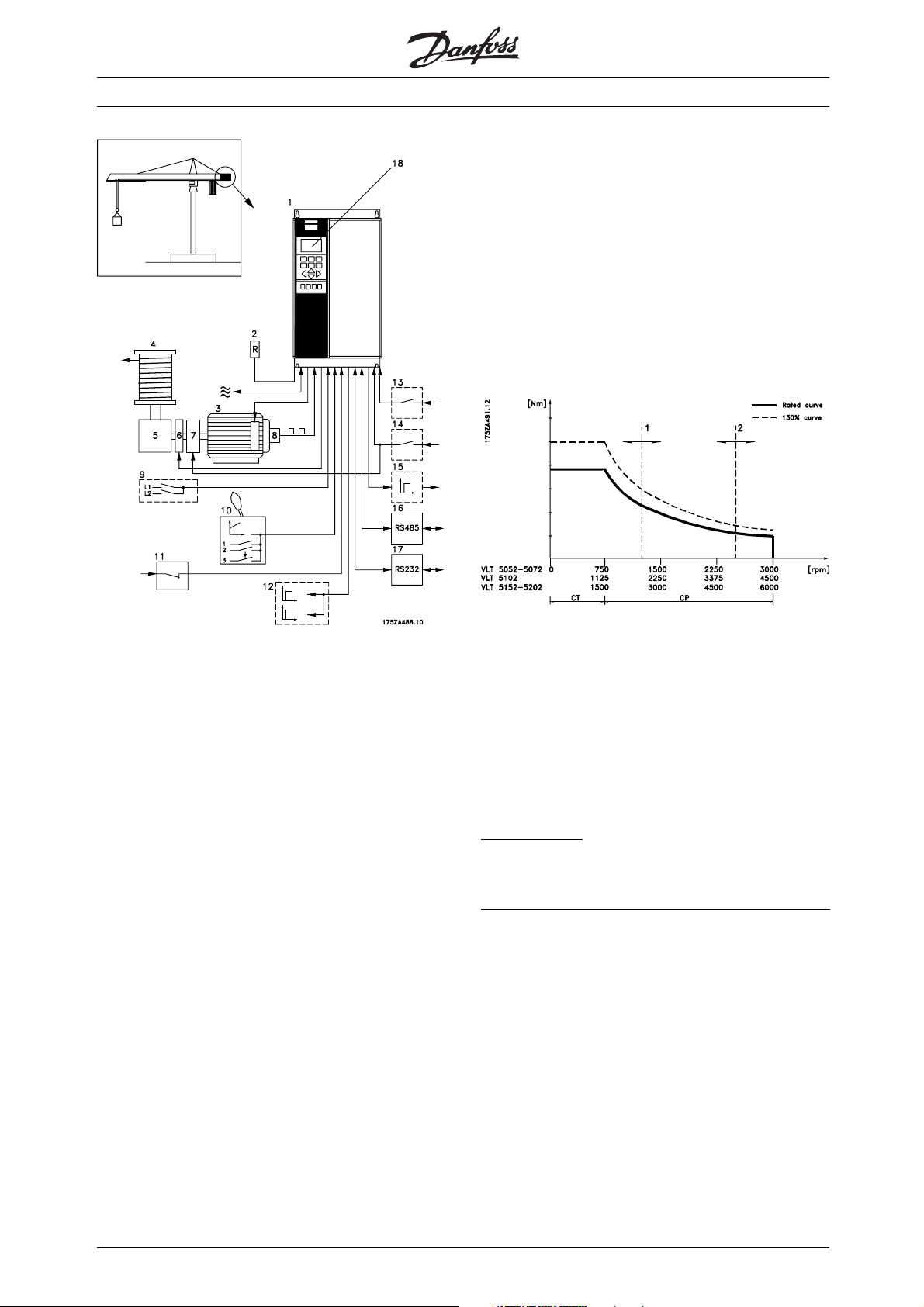
The sketch on next page shows how a tower crane
works together with VLT Crane Control.
The system consists of the following:
Efficient monitoring of the mains supply phases
ensures that the unit stops in case of phase failure.
This eliminates the risk of overloading the inverter an
the capacitors in the intermediate circuit and thereby
prolongs the service life of the frequency converter.
As standard, VLT 5000 Crane features integral
thermal protection. If a situation of thermal overload
occurs, this function cuts out the inverter.
The VLT 5000 Crane features reliable galvanic isolation
on all control terminals and integrated electronic
thermal protection on the motor.
■Function and System Description
With VLT 5000 Crane the speed is infinitely varied in the
whole speed range from standstill (0 RPM) until rated
speed (750 RPM for VLT 5052-5072, 1125 RPM for
VLT 5102) according to the CT characteristic and rated
power up to max. speed (3000 or 4500 RPM).
There is full torque in the whole speed range.
1. VLT 5000 Flux Vector Control
2. Brake resistor
d
3. Motor
4. Cable drum
5. Angular gear box
6. NC system brake
7. Electric 2-step-gears: Normal load and heavy load
8. Optical encoder: Motor speed information for
flux vector control with closed loop
9. Load signals: VLT 5000 Crane checks on the basis of
load signals that the working range is not exceeded
10. Control signal: Analogue reference as well as
hoist, lowering and position operation
11. Quick stop with brake
12. Digital outputs: For combination of warning
and alarm at your operation
13. Crane ready signal
14. Gear step selection signal
15. VLT ready signal
16. RS 485 bus
17. RS 232 bus
18. Local control panel
MG.50.N4.02 - VLT is a registered Danfoss trademark
Installation and mains connection of brake resistor
and motor are described in Electrical installation
9
Page 11
VLT® 5000 Crane
■Description of Functions
With Danfoss VLT 5000 Crane the hoist/lower function
can be infinitely varied in the whole speed range.
Up to 750 RPM for VLT 5052-5072, 1125 RPM for
VLT 5102, 1500 RPM for VLT 5152-5202, respectively
themax. torquecurveappliesandabove750
RPM for VLT 5052-5072, 1125 RPM for VLT 5102,
1500 RPM for VLT 5152-5202, respectively the
max. power curve. There is up to 130% torque for
acceleration in the whole speed range.
Working curve, motor:
1: Speed limit at heavy load (parameter 702)
2: Speed limit at normal load (parameter 701)
The 2-step gear box (see System description )
increases the working range, as it is possible to switch
between normal load and heavy load.
VLT 5000 will optimise the motor control to the selected
gear stage on the basis of the signal on terminal
29, see System Description, position 14.
ignal definition
S
24 V signal: Normal load
0 V signal: Heavy load
■Operating Status at Remote Control
Control ready
Voltage on VLT 5000 Crane. The frequency
converter is ready for use and the control card
receives supply voltage.
No faults were found during initialisation.
Inverter section disabled.
10
Normal operation
The reference signal is higher than minimum. Up to
750 RPM the working range is limited by max. torque.
Above 750 RPM it is working in field weakening range.
Here the working range is limited by constant power.
MG.50.N4.02 - VLT is a registered Danfoss trademark
Page 12

VLT 5000 Crane controls the mechanical brake
of the crane. It holds the load when speed is
below the set minimum value.
VLT 5000 Crane monitors that the system brake
holds and releases the load as required. In case
of faults, Brake fault 2 is displayed.
Load determination and speed measuring will ensure
that the working range is not exceeded. For each
load contact the max. allowed motor speed is set
(parameters 701 and 702). VLT 5000 Crane cuts off
automatically when motor speed for the activated
load contact exceeds the value recorded
Positioning
The reference signal is higher than minimum. The
condition for VLT ready is fulfilled. 24V is applied
to terminal 17 (parameter 301).
During positioning the speed is limited to 750 RPM
for VLT 5052-5072, 1125 RPM for VLT 5102, 1500
RPM for VLT 5152-5202, respectively, and system
brake is not activated at 0 RPM.
Quick stop with brake
If control signal to terminal 27(parameter 304)
is removed, the motor ramps down according
to the alternative ramp (parameter 212) and the
brake is activated momentarily.
■Operating Status at Local Operation
It is only possible to change to local operation from
Control Ready. Besides, parameter 003 must be
set for Local and parameter 010 for Enable.VLT
5000 Crane can be operated over the control panel
or over parameters 004 - 009. This state acts
as Normal operating state, however there are no
load functions and monitoring of system brake.
This means that the whole working range from 0
- 3000 RPM can be used and the crane system
brake is controlled at approx. 0 RPM.
VLT® 5000 Crane
Brake fault 2
VLT 5000 Crane monitors in the state normal operation,
that the system brake releases the load as required.
If that is not the case Brake fault 2 applies. The unit
will cut in the system brake again. This means that the
system brake signal is deactivated. This ensures that
the load is held. Then the inverter section is disabled.
Brake fault 2 may also occur during commissioning
if the encoder connection is not correct.
Atreference0theunitgoesbacktothestateVLTready.
Function fault
VLT 5000 Crane monitors several functions. Should
severe faults occur, the unit will trip automatically.
For fault types, see Trouble-shooting
To reset the fault switch off/switch on the mains
supply and press the stop/reset button.
■System Components
Motor
Select the motor type for the rated output in question
in parameters 102-106, 150-155..
Incremental Encoder
The encoder must meet the following requirements:
• Pulses pr. revolution, see parameter 329
• Out puts: A (0º ), inv. A, B ( 9 0 º), inv. B, Z, i nv. Z
• Supply: +5 V ±5%
• Max. current (5V supply): 200mA
Note that outputs must be compatible with RS 422!
Brake resistor
See data for calculation in Control with brake function.
Introduction
■Fault Status at Remote and Local Control
Brake fault 1
VLT 5000 Crane monitors in the state VLT ready that
the system brake holds the load as required. If that is
not the case, Brake fault 1 appliesandtheloadisslowly
lowered according to the speed set in parameter 704.
MG.50.N4.02 - VLT is a registered Danfoss trademark
11
Page 13
VLT® 5000 Crane
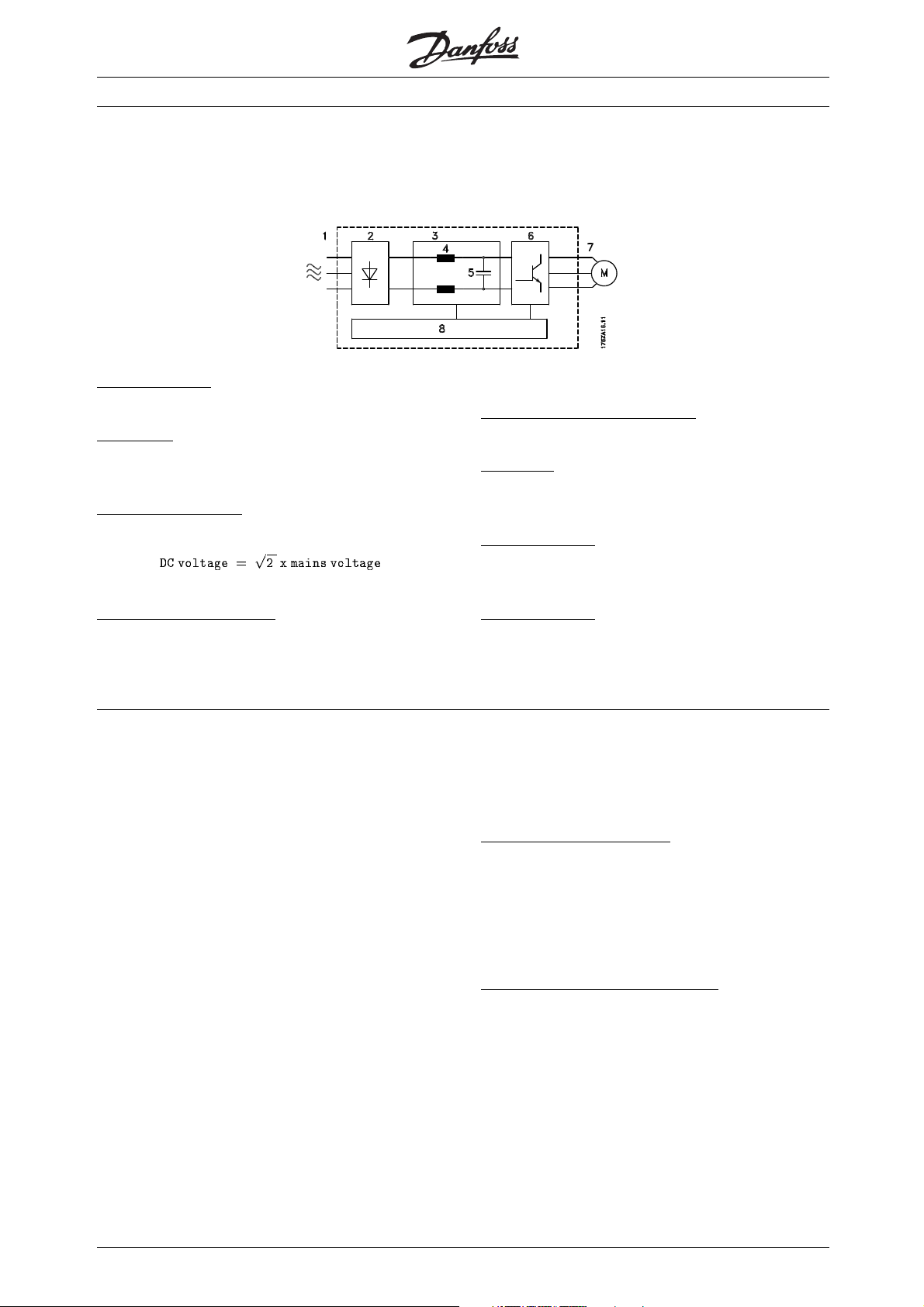
■Control Principle
A frequency converter rectifies AC voltage from mains
into DC voltage. This DC voltage is then converted into
aACvoltagewithavariableamplitudeandfrequency.
1. Mains voltage
3 x 400 - 500 V AC, 50 / 60 Hz.
2
. Rectifier
A three-phase rectifier bridge that rectifies AC
voltage into DC voltage.
3
. Intermediate circuit
The motor is thus supplied with variable voltage and
frequency, which enables infinitely variable speed
control of three-phased, standard AC motors.
5
. Intermediate circuit capacitors
Smooth the intermediate circuit voltage.
. Inverter
6
Converts DC voltage into variable AC voltage
with a variable frequency.
. Motor voltage
7
Variable AC voltage, 0-100% of mains supply voltage.
Variable frequency: 0 - 300 Hz.
4. Intermediate circuit coils
Smooth the intermediate circuitcurrent and limit the
load on mains and components (mains transformer,
wires, fuses and contactors).
■Flux Vector Control Principle
TheaimofdevelopingtheFluxVectorcontrol
principle has been to obtain a robust motor control
that is tolerant to different motor characteristics
without motor derating being required.
The current is split into magnetising and
torque-generating parts and provides for much
better and quicker estimation of the actual motor
loads. It is now possible to compensate for rapid
load changes. Full torque as well as extremely
accurate speed control can now be obtained even
at low speeds or even at standstill.
Good torque control properties and smooth transitions
to and from current limit operation are ensured.
Advantages of the Flux Vector control system:
- Accurate speed control down to 0 speed
- Quick response from received signal to
full motor shaft torque
- Good compensation for step loads
- Controlled transition from normal operation to
current limit operation (and vice versa)
. Control circuit
8
On basis of parameters, reference settings and input
signals, pulse patterns are generated for forming
thevariablemotorvoltageandfrequency.
- Torque control, comprising control of both
the torque-generating and the magnetising
component of the current
- Full holding torque
P
rogrammable signal outputs
VLT 5000 Crane uses a digital technique which makes
it possible to program the signal outputs.
For the user, it is easy to program the desired functions
by means of the control panel on VLT 5000 Crane
or the RS 485/RS 232 user interfaces.
rotection against mains interference
P
VLT 5000 Crane is protected against the transients
that occur in the mains supply, eg. when switching
power factor correction or when fuses blow.
The rated motor voltage and full torque can be
maintained all the way down to 10% undervoltage
in the mains supply.
12
MG.50.N4.02 - VLT is a registered Danfoss trademark
Page 14

VLT® 5000 Crane
Minor interference on mains
Since as standard the VLT 5000 Crane features
intermediate circuit coils, there is only a small amount
of harmonic mains supply interference. This ensures
a good power factor and lower peak current, which
reduces the load on the mains installation.
A
dvanced VLT protection
Current measurement on all three motor phases
provides perfect protection of VLT 5000 Crane
against earthing and short-circuiting faults on
the motor connection.
Efficient monitoring of the three mains supply phases
ensures that the unit stops in the case of phase failure.
This avoids overloading the inverter and the capacitors
in the intermediate circuit, which would dramatically
reduce the service life of the frequency converter.
As standard, VLT 5000 Crane features integral
thermal protection. If a situation of thermal overload
occurs, this function cuts out the inverter.
ncoder supervisory circuit
E
The signals from the incremental encoder and hence
the cabling are continuously supervised.
The encoder signals are made up of three channels,
each of which are supervised, and status is given
on LEDs placed near the encoder terminals for each
channel as well as for the supply voltage for the encoder.
Green LED turned on means channel or voltage OK.
fan fails, a thermistor can be integrated and connected
to the thermistor input of the frequency converter
(terminals 53), see parameters 128 and 308.
Introduction
R
eliable galvanic isolation
In the VLT 5000 Crane all of the control circuits are
separated from mains potential through isolation
meeting the PELV requirements.
One set of relay contacts, terminals 01 - 03, is
separated from the remaining control circuits through
isolation also complying with PELV.
Furthermore, the control circuits are placed in blocks
individually separated through functional isolation
(< 100 V), see General Technical Data.
A
dvanced motor protection
VLT 5000 Crane features integrated
thermal motor protection.
The frequency converter calculates the motor
temperature on the basis of current, frequency and time.
As opposed to the traditional bimetallic protection,
electronic protection takes ac
cooling at low frequencies that comes from reduced
fan speed (motors with internal ventilation).
To obtain maximum protection against overheating of
the motor if the motor is covered or blocked, or if the
count of the reduction in
electronic,
MG.50.N4.02 - VLT is a registered Danfoss trademark
13
Page 15
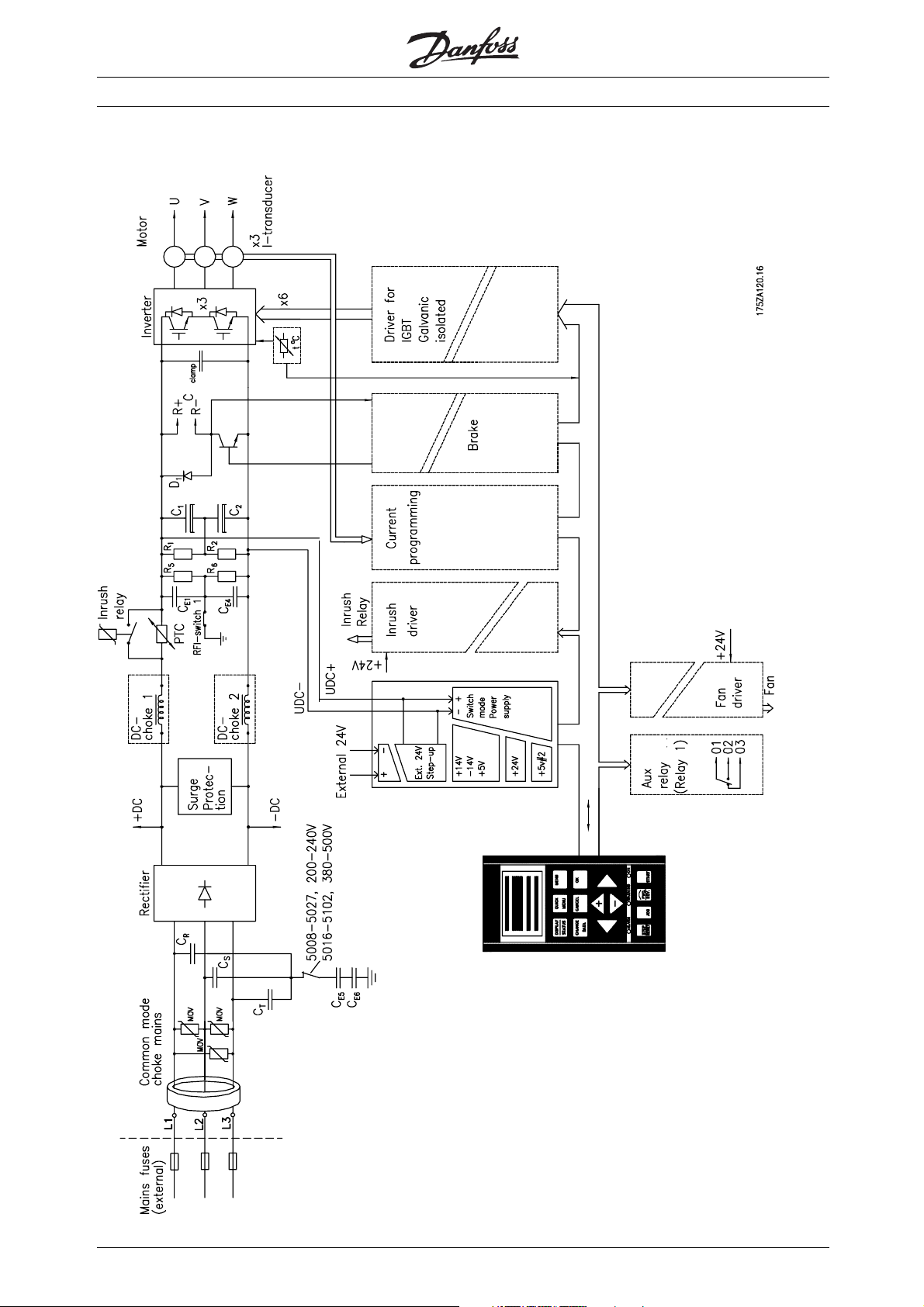
■Key Diagram for VLT 5000 Crane 5042,
5102 400-500 V
VLT® 5000 Crane
14
MG.50.N4.02 - VLT is a registered Danfoss trademark
Page 16
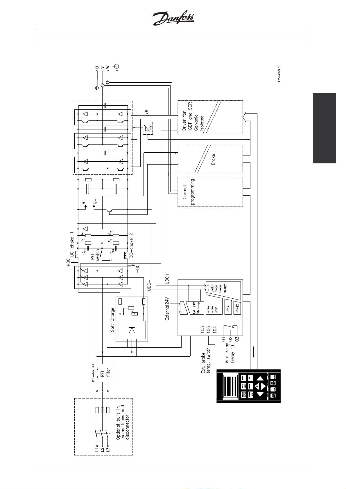
■Key Diagram for VLT 5000 Crane 5122-
5202 400-500 V
VLT® 5000 Crane
Introduction
MG.50.N4.02 - VLT is a registered Danfoss trademark
15
Page 17
VLT® 5000 Crane
■General Technical Data
Mains Supply (L1, L2, L3)
Supply voltage 400 - 500 V units 3 x 400/415/440/460/500 V ± 10%
Supply frequency 50/60 Hz ± 1%
Max. imbalance of supply voltage
VLT 5052 - 5062/400 - 500 V
VLT 5072 - 5202/400 - 500 V
Power factor/cos ϕ
No. of switches on supply input L1, L2, L3 Appr. 1 time/minute
Max. short-circuit rating 100.000 A
Output voltage 0-100% of supply voltage
Output frequency 0-160 Hz
Rated motor voltage 400 - 500 V units 315 V
Rated motor frequency 25/37 Hz
Ramp times 0.05 - 3600 Seconds
Starting torque, VLT 5042–5202, 400 - 500 V 160%
Acceleration torque, VLT 5042–5302, 400 - 500 V 160%
Overload torque, VLT 5042-5302, 400 - 500 V 160%
Holding torque at 0 rpm (closed loop), VLT 5042–5302, 400 - 500 V 160%
1
VLT Data Output (U, V, W)
Torque Characteristics
of rated supply voltage
1.5%
3%
0.90/1 at rated load
for 1 minute
for 1 minute
for 1 minute
for 1 minute
Digital Inputs
Number of digital inputs 9
Voltage level 0-24 V DC (PNP positive logics)
Voltage level, logical ’0’ <5 V DC
Voltage level, logical ’1’ >10 V DC
Max. voltage on input 28 V DC
Input resistance, Ri(terminal 29) Appr. 4 K /2 K (2 K )
Scanning time per input 3msec
NOTE: All digital inputs are galvanic isolated from the mains voltage (PELV). In addition, the digital inputs can be isolated from the other
terminals on the control card by connecting an external 24 V DC supply and opening switch 4, see Electrical installation.
Analogue Inputs
Number of programmable analogue voltage inputs/thermistor inputs 1
Voltage level 0- ± 10 V DC (Scalable)
Input resistance, R
Number of programmable analogue current inputs 2
Current range 0/4- 20 mA (Scalable)
Input resistance, R
Resolution 10 + sign bit
Accuracy on input Max. error: 1% of full scale
Scanning time per input 3msec
NOTE: Analogue inputs are galvanic isolated from the mains voltage (PELV) and functionally isolated from all other inputs
i
i
Appr. 10 K
200
16
MG.50.N4.02 - VLT is a registered Danfoss trademark
Page 18
VLT® 5000 Crane
Incremental/Encoder Input
Number of encoder input terminals 6
Max. frequency 205 kHz
Voltage level 0-5 V (RS422)
Voltage level, logical ’0’ <0.5V
Voltage level, logical ’1’ >2.5V
Max. voltage on input 7VDC
Input resistance, R
Supply voltage 5V+/-5%
Supply current 200 mA
NOTE: Encoder input terminals are galvanic isolated from the supply voltage (PELV) and functionally isolated from all other inputs
and outputs.
Number of programmable digital outputs 2
Number of programmable analogue outputs 2
Voltage level at digital/pulse output 0-24 V DC
Min. load to ground (terminal 39) at digital/pulse output 600
Frequency ranges (digital output used as pulse output) 0-50 kHz
Resolution
<5kHz
<50 kHz
Current ranges at analogue output 0/4-20 mA
Max. load to ground (terminal 39) at analogue output 500
Accuracy of analogue output Max error: 1.5% of full scale
Resolution on analogue output 8bit
NOTE: All digital and analogue outputs are galvcanic isolated from the supply voltage (PELV) and functionally isolated from all other inputs
NB: Digital and analogue outputs have one common ground terminal (39)
i
Digital/Pulse and Analogue Outputs
Appr. 120
0.1%
1%
Data
Technical
24 V DC Output
Max. load (short-circuit protection) 200 mA
Terminal numbers, ground (with switch 4 closed) 39 (20)
NOTE: The 24 V DC supply is galvanic isolated from the supply volta
outputs
RS 485 Serial Communication
Terminal numbers 68 (TX+, RX+), 69 (TX-,RX-)
NOTE: The signal input is galvanic isolated from the mains volta
RS 232 Serial Communication (Peer to Peer)
Connection RJ 11
NOTE: The signal input is galvanic isolated from mains supply (PELV) but not from RS 485
ge (PELV), but has the same potential as analogue and digital
ge (PELV) but not from RS 232
MG.50.N4.02 - VLT is a registered Danfoss trademark
17
Page 19
VLT® 5000 Crane
Relay Outputs
Number of programmable relay outputs 2
Terminal numbers, control cards 4-5 NO
Max. terminal load (AC) on 4-5 control card 50 V AC, 1A, 60 VA
Max. terminal load (DC) on 4-5, control card 75 V DC, 1A, 30W
Max. terminal load (DC) on 4-5, control card
UL applications
cUL applications
Terminal numbers, power card 1-3 NC, 1-2 NO
Max. terminal load (AC) on 1-3, 1-2, power card 240 V AC, 2A, 60 VA
Max. terminal load on 1-3, 1-2, power card 50 V DC, 2 A
Min. terminal load on 1-3, 1-2, power card 24 V AC/24 V DC, 10/100mA
Brake Resistor Terminal
Terminal numbers 81, 82
Cable Lenghts and Cross-Sections
Max. motor cable length, screened cable 25m
Max. brake cable length, screened cable 5m
Max. cable cross-section for control cables 0.75mm2/AWG
Max. cross-section for serial communication 0.75mm2/AWG
NOTE: Max. cable cross-section for motor and brake, see Installation
30 V AC, 1A
1A, 42.5 V DC
Accuracy of Display Readout (Parameters 009 - 012)
Motor Current [6] 0 - 140% load Max error: 2% of rated output current
Torque % [7] -100 - 140% load Max error: 5% of rated motor size
Output [8], power HP [9] 0 - 90% load Max error: 5% of rated output
Control Caracteristics
Frequency range 0-160 Hz
Resolution on output frequency ± 0.003 Hz
System response time* <5msec
Speed, control range 1:1000 of synchro speed
Speed, accuracy
<1500 rpm
>1500 rpm
Torque control accuracy (Speed feedback) Max error: ± 5% of rated torque
NOTE: All control caracteristics are based on 4-pole asynchronous motors
Max error:
±1.5rpm
0.1% of actual speed
*The system response time is the time passing
from the input receives a signal to a reaction
occurs on the VLT output.
18
MG.50.N4.02 - VLT is a registered Danfoss trademark
Page 20

VLT® 5000 Crane
Externals
Enclosure Ty pe IP 20 /I P 0 0
Vibration Test: 0.7 g RMS 18 - 100 Hz random, 3
directions for 2 hrs (IEC 68-2-34/35/36)
Max. relative humidity for storage/transport 93% (IEC 68-2-3)
Max. relative humidity non-condensing for operation 95% (IEC 721-3-3; Class 3K3)
Ambient temperature 55°C
Ambient temperature, 24-hour average Max 50°C
Min. ambient temperature in full operation 0°C
Min. ambient temperature at reduced performance -10°C
Temperature during storage/transport -25 - +65/70°C
Max. altitude above sea level, without derating* 1000m
NOTE: EMC standards used:
Emission: EN50081-1/2, EN61800-3, EN55011,
Immunity: EN50082-2, EN61000-4-2,, EN61000-4-4,ENV50204, EN61000–4–3, EN61000–4–5, EN61000–4–6, VDE0160/1990.12
Derating for high ambient temperature, see Special Conditions in Appendix
*For more information on derating, see Special
Conditions in Appendix.
■VLT 5000 Crane Protection
• Electronic motor thermal protection against overload
• Electronic thermal protection against overload
• Temperature monitoring of heat-sink ensures that the frequency converter cuts out if the temperature reaches
90°C. An overtemperature fault can only be reset when the temperature of the heat-sink has fallen below 60°C
• The frequency converter is protected against short-circuiting on motor terminals U, V, W
• The frequency converter is protected against earth fault on motor terminals U, V, W
• Monitoring of the intermediate circuit voltage ensures that the frequency converter cuts out if
the intermediate circuit voltage gets too high or too low
• If a motor phase is missing, the frequency converter cuts out, see parameter 234 Motor Phase Monitor
• If a mains phase is missing, the frequency converter will cut out when a load is applied to the motor
Data
Technical
MG.50.N4.02 - VLT is a registered Danfoss trademark
19
Page 21
VLT® 5000 Crane
■Mains Supply 400 - 500 V
According to international requirements VLT type 5042 5052 5062
I
(S3 60%) [A]
Output current
Output
Typical shaft output P
Typical shaft output P
Max. cable cross-section to motor and
brake [mm
2
Rated input current I
Max. cable cross-section
power[mm2]/[AWG]
Max. pre-fuses [-]/UL1)[A] 100/100 125/125 150/50
Efficiency 0.96 0,96 0.96
Weight IP 20 SB [kg] 41 42 43
Power loss at max. load. 1004 1210 1500
Enclosure IP20 IP20 IP20
1. For type of fuse see section Fuses.
2. American wire gauge.
3. Connection stud 1 x M8/2 x M8.
]/[AWG]
I
VLT, MAX
2)3)
2)3)
VLT,N
(400-500 V)
58 69 85
(60 s) [A] (400-500 V) 97.6 116.8 135
S
(S3 60%) [kVA]
VLT,N
(400-500 V)
VLT,N
VLT,N
39.2
46.6 57.4
[kW] 22 30 37
[HP] 30 41 50
IP20 50/0 50/0
(S3 60%) [A] (400 V) 51 62 76
L,N
35/2 50/0 50/0
20
MG.50.N4.02 - VLT is a registered Danfoss trademark
Page 22
VLT® 5000 Crane
■Mains supply 3 x 400-500 V
According to international
requirements VLT type 5072 5102 5152 5202
Output
current
Output
Typical shaft output P
Typical shaft output P
Max. cable cross-section to motor
(400-500 V) [mm
Max. cable cross-section to brake
(400-500 V) [mm2]
Max. cable cross-section to motor
(400-500 V) AWG]
Max. cable cross-section to brake
(400-500 V) AWG]
Max input current I
Max. cable cross-section to power
(400-500 V) [mm
Max. cable cross-section to power
(400-500V) [AWG]
Efficiency
Weight IP 20 EB/IP 00 [kg] 109 109 89 134
Power loss at max. load [W] 1860 2250 2828 3231
Enclosure IP20 IP20 IP00 IP00
1. For type of fuse see section Fuses.
2. American wire gauge.
3. Connection Dual M10 screws.
4. Connection Dual M8 screws.
I
[A] (S3 60%) (400-500 V) 100 139 201 246
VLT,N
I
VLT, MAX
(60 s) [A] (400-500 V) 159 221 301 369
S
(S3 60%) [kVA]
VLT,N
(400-500 V) 67.5 93.9 135.8 166.2
[kW] 45 65 90 110
VLT,N
[HP] 61 89 125 150
VLT,N
2]3)
2) 3)
2) 4)
2]3)
4)
2) 3)
(S3 60%) [A] (400 V) 89 124 186 224
L,MAX
95 120 2x70 2x185
95 120 2x35 2x70
3/0 4/0 2x2/0
3/0 4/0 2x3 2x2/0
95 120 2x70 2x185
3/0 4/0 2x2/0
0.96-
0.97
0.96-
0.97
0.97-
0.98
2x350
MCM
Data
Technical
2x350
MCM
0.97-
0.98
MG.50.N4.02 - VLT is a registered Danfoss trademark
21
Page 23
VLT® 5000 Crane
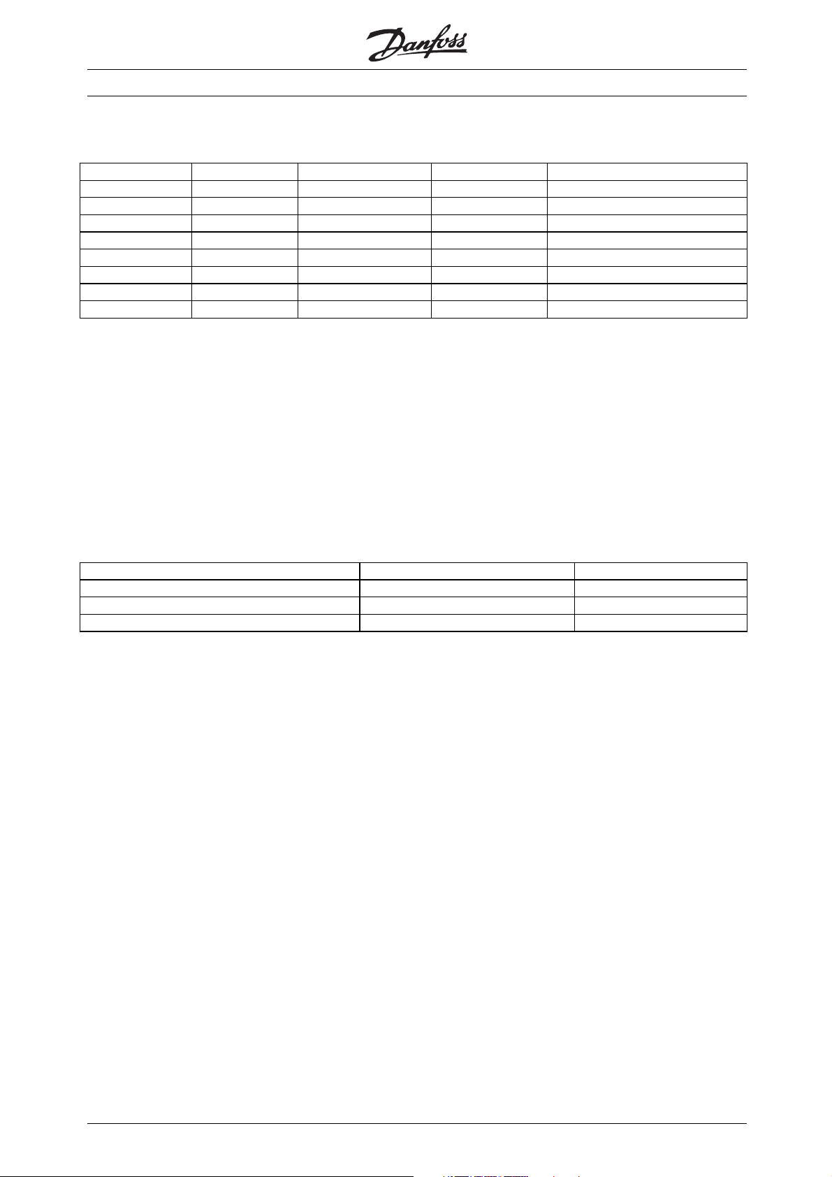
■Fuses
UL compliance
Bussmann SIBA Littel fuse Ferraz-Shawmut
5042 KTS-R100 2028220-125 KLS-R100 A6K-100R
5052 KTS-R125 2028220-125 KLS-R125 A6K-125R
5062 KTS-R150 2028220-160 KLS-R150 A6K-150R
5072 FWH-220 2028220-200 L50S-225 A50-P225
5102 FWH-250 2028220-250 L50S-250 A50-P250
5122 FWH-300 2028220-315 L50S-300 A50-P300
5152 FWH-350 2028220-315 L50S-350 A50-P350
5202 FWH-400 206xx32-400 L50S-400 A50-P400
KTS-fuses from Bussmann may substitute KTN for 240 V drives.
FWH-fuses from Bussmann may substitute FWX for 240 V drives.
KLSR fuses from LITTEL FUSE may substitute KLNR fuses for 240 V drives.
L50S fuses from LITTEL FUSE may substitute L50S fuses for 240 V drives.
A6KR fuses from FERRAZ SHAWMUT may substitute A2KR for 240 V drive
A50X fuses from FERRAZ SHAWMUT may substitute A25X for 240 V drives.
Non UL
compliance
380-500 V
s.
If UL/cUL is not to be complied with, we recommend the above mentioned fuses or:
VLT 5001-5027 200-240 V type gG
VLT 5001-5062 380-500 V type gG
VLT 5032-5052 200-240 V type gR
VLT 5072-5500 380-500 V type gR
Not following the recommendation may result
in unnecessary damage of the drive in case of
malfunction. Fuses must be designed for protection in
a circuit capable of supplying a maximum of 100000
A
(symmetrical), 500/600 V maximum.
rms
22
MG.50.N4.02 - VLT is a registered Danfoss trademark
Page 24
VLT® 5000 Crane
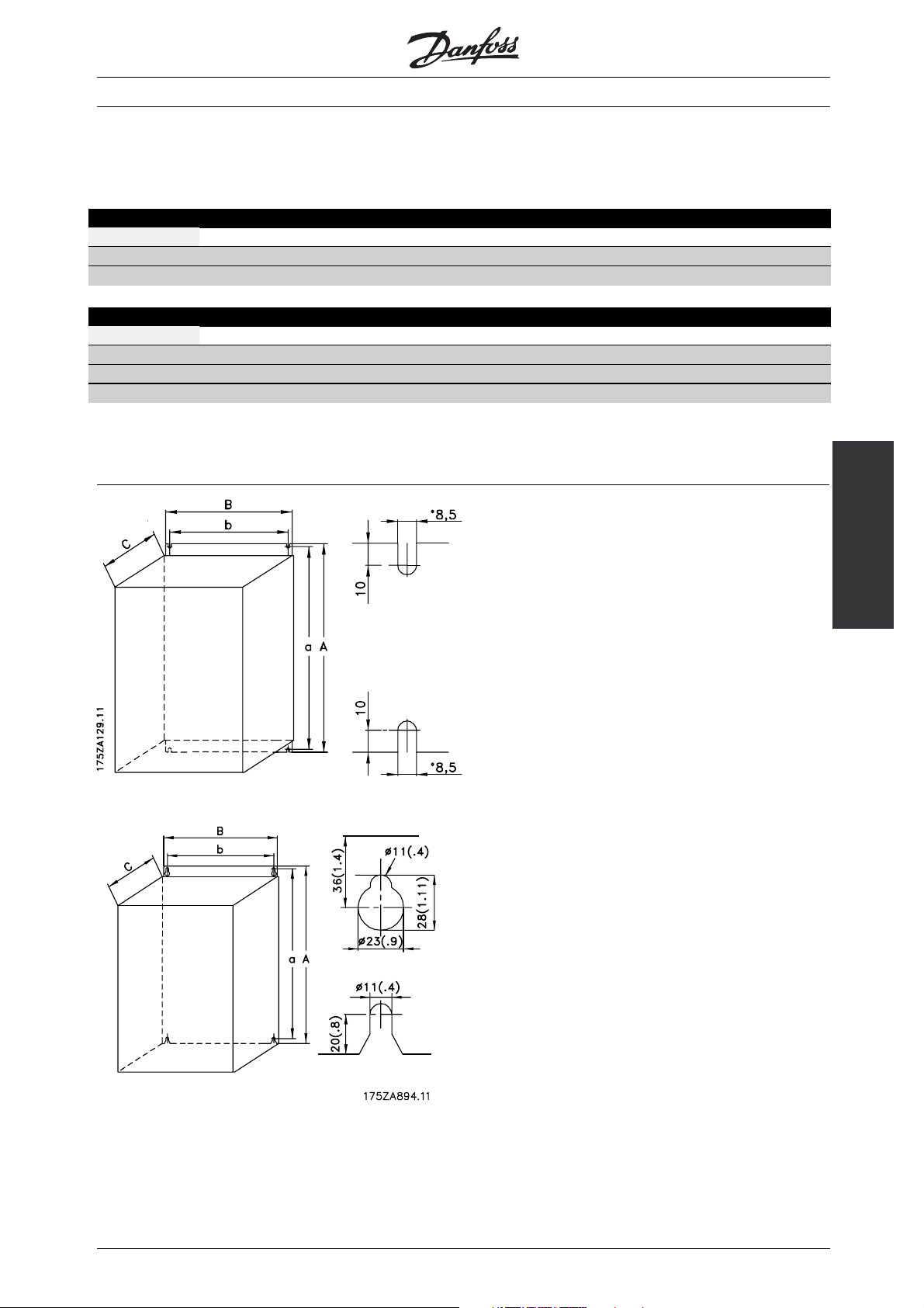
■Mechanical Dimensions
■Compact IP 00 and IP 20
IP 00 enclosure 400-500 V
VLT type A (mm) B (mm) C (mm) a (mm) b (mm) ab/be (mm) l/r (mm)
5152 - 5202 1400 420 400 1380 350 225 0
IP 20 enclosure 400-500 V
VLT type A (mm) B (mm) C (mm) a (mm) b (mm) ab/be (mm) l/r (mm)
5042 - 5062 800 308 296 780 270 200 0
5072 - 5102 800 370 335 780 330 225 0
ab: Min. space above enclosure.
be: Min. space below enclosure.
l/r: Min. distance between frequency converter and
other plant components, left and right sides.
VLT 5042-5102/400-500 V
Data
Technical
VLT 5152-5202/400-500 V
MG.50.N4.02 - VLT is a registered Danfoss trademark
23
Page 25
VLT® 5000 Crane
■General Warning before Installation
Before starting the installation, please
be aware of heavy weight and sharp
edges. Furthermore, make sure that
no mains are connected
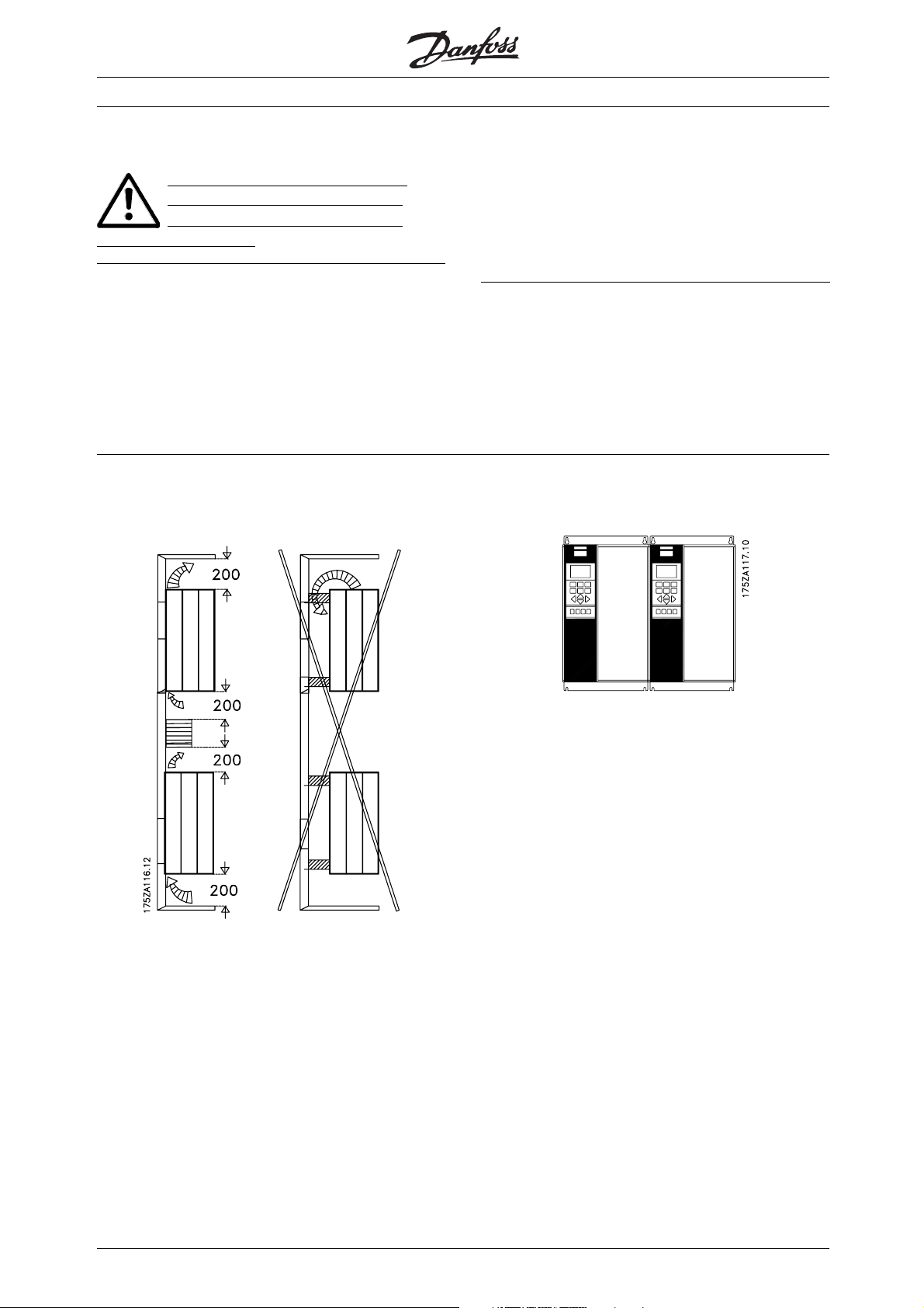
■Mechanical Installation
The frequency converter must be installed vertically.
The frequency converter is cooled by means of air
circulation. For the unit to be able to release its cooling
air, the minimum distance over and below the unit
must be as shown in the illustration below. To protect
■Installation of VLT 5042–5062 400-500 V
Compact IP20/IP00
Cooling
the unit from overheating, it must be ensured that the
ambient temperature does not rise above the max.
temperature stated for the frequency converter and
that the 24-hour average temperature is not exceeded.
The max. temperature and 24-hour average can be
seen from the General Technical Data.
■Enclosure Protection
Compact
VLT 5042 - 5102 400-500 V IP 20
VLT 5152 - 5202 400-500 V IP 00
Side-by-side
All Compact units in the above-mentioned series
require a minimum space of 200 mm above and
below the enclosure and must be installed on a
plane, vertical surface (no spacers).
Compact IP 00/IP20
All units in the above-mentioned series can be installed
side by side without any space between them, since
these units do not require cooling on the sides.
24
MG.50.N4.02 - VLT is a registered Danfoss trademark
Page 26

■Installation of VLT 5072-5202 400-500 V
Compact IP20/IP00
Cooling
All Compact units in the above-mentioned series
require a minimum space of 225 mm above and
below the enclosure and must be installed on a
plane, vertical surface (no spacers).
VLT® 5000 Crane
Side-by-side
Compact IP 00/IP20
All units in the above-mentioned series can be installed
side by side without any space between them.
■Ventilation when Panelmounted
The quantity of air needed to cool VLT 5000 Crane
can be calculated as follows:
1. Add up the values of P
to be installed at the same panel (
2. Determine the air inlet temperature (t
air outlet temperature (t
for all VLT 5000 Crane
P )[W]
)andthe
IN
)[ºCorK]
OUT
3. Calculate the necessary air quantity in m
Insert t
OUT-tIN
in Kelvin
• The output from the fan must be located above
the highest mounted frequency converter
• Remember to take pressure drops over filters
into account and that the pressure decreases
as the filters are choked
• The max. cooling air temperature (t
)must
IN
be lower than 55ºC. The average of day/night
temperature may be 5ºC lower than that stated
in VDE 160. The cooling outlet temperature
(t
) may not exceed 60ºC
OUT
3
/h:
Installation
MG.50.N4.02 - VLT is a registered Danfoss trademark
25
Page 27
■Electrical Installation
The voltage on the frequency converter is
dangerous when the unit is connected to
mains. Incorrect installation of the motor
or frequency converter may lead to material damage
or serious injury or it may be fatal. Consequently, the
instructions in this manual as well as national and
local rules and safety regulations must be complied
with. Touching the electrical parts may be fatal, even
after the mains supply has been disconnected. Wait
at least 15 minutes if using VLT 5052-5102.
NB!:
It is the user’s or certified electrician’s
responsibility to ensure correct earthing and
protection in accordance with applicable
national and local norms and standards.
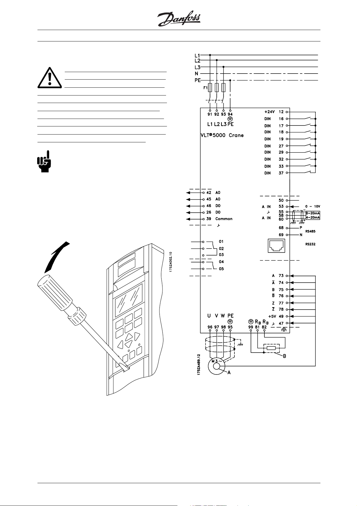
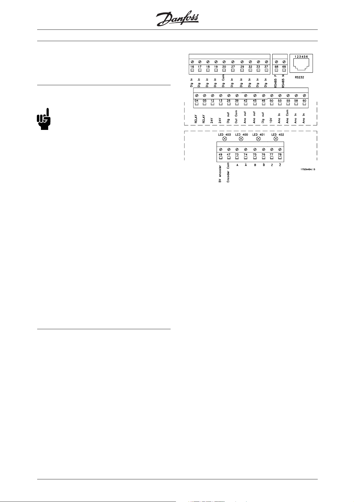
All terminals for the control cables are located under
the protective cover of the frequency converter. The
protective cover (see drawing) can be removed by
means of a pointed object - a screwdriver or similar.
VLT® 5000 Crane
Once the protective cover has been removed, the
actual EMC-correct installation can start.
26
Wiring diagram VLT 5000 Crane
A: Encoder
B: Brake resistor
12: +24 V
16 Crane ready (NO)
17: Positioning (NO)
18: Lower (NO)
19: Hoist (NO)
20: Ground for digital inputs
26: Digital output
27: Quick stop (NC)
29: Gear ratio select (NO)
32: Load low (NO)
MG.50.N4.02 - VLT is a registered Danfoss trademark
Page 28

33: Load high (NO)
37: Hardware coast (NC)
39: Ground for analogue/digital outputs
42: Analogue output warning/alarm
45: Analogue output warning/alarm
46: Digital output
50: 10 V supply
53: Reference voltage
55: Common for anal. ref.
60: Reference current
68, 69: RS 485
01, 02: System brake signal
04, 05: Ready signal
73: Pulse signal A from encoder (0°)
74: Inverted pulse signal from encoder (0°)
75: Pulse signal B from encoder (90°)
76: Inverted pulse signal B from encoder (90°)
77: Zero pulse signal from encoder
78: Inverted zero pulse signal from encoder
49: 5 V supply to encoder
47: Common for encoder supply
VLT® 5000 Crane
■Electrical Installation, Power Cables
Compact IP 20 VLT Type 5042–5062
Compact IP 00 VLT 5125-5250 400-500 V
■Connection of Mains
Connect the three mains phases to terminals L
■Connection of Motor
All types of 3-phased asynchronous standard motors
can be used with the VLT 5000 Crane.
1,L2,L3
.
Installation
Compact IP 20/IP 00 VLT Types 5072-5102
MG.50.N4.02 - VLT is a registered Danfoss trademark
27
Page 29
Normally, small motors are star-connected.
Large motors are delta-connected.
Note the voltage value at the type plate.
■Installation of Motor Cables
NB!:
If an unscreened cable is used, some EMC
requirements are not complied with, see
Special conditions in Appendix.IftheEMC
specifications regarding emission are to be complied
with, the motor cable must be screened, unless
otherwise stated for the RFI filter in question. It is
important to keep the motor cable as short as possible
to reduce the noise level and leakage currents to a
minimum. The motor cable screen must be connected
to the metal cabinet of the frequency converter and to
the metal housing of the motor. The screen connections
are to be made with the biggest possible surface
(cable clamp). This is enabled by different installation
devices in the different frequency converters.
Mounting with twisted screen ends (pigtails) is to
be avoided, since these spoil the screening effect
at higher frequencies. If it is necessary to break
the screen to install a motor isolator or motor
contactor, the screen must be continued at the
lowest possible HF impedance.
VLT® 5000 Crane
LEDs on encoder board:
When all LEDs are on the connection to encoder
and encoder condition are OK.
LED 403 OFF: 5 V supply missing
LED 400 OFF: Channel A or inv. A missing
or shortcircuited
LED 401 OFF: Channel B or inv. B missing
or shortcircuited
LED 402 OFF: Channel Z or inv. Z missing
or shortcircuited.
The frequency converter has been tested with a given
length of cable and a given cross-section of that cable.
If the cross-section is increased, the cable capacitance
- and thus the leakage current - increases, and the
cable length must be reduced correspondingly.
■Installation of Control Cables
Tightening-up torque: 0.22 - 0.25 Nm
Screw size: M2
Screw driver type: 0.4 x 2.5 x 80 mm
See Earthing of Braided Screened/Armoured
Control Cables for correct earthing.
28
MG.50.N4.02 - VLT is a registered Danfoss trademark
Page 30
Connection of shield:
VLT® 5000 Crane
The connection cable to the brake resistor must
be screened/armoured. Connect the screen to the
metal cabinet of the frequency converter and to
the metal cabinet of the brake resistor by means of
cable clamps. Dimension the cross-section of the
brake cable to match the brake torque.
NB!:
Please note that voltages up to 850 V DC
occur on the terminals.
No. Function
12, 13 Voltage supply to digital inputs.
Forthe24VDCtobeusable
for the digital inputs, switch 4 on
the control card must be closed
position "ON".
Max. current 350 mA
16-33 Digital inputs
37 Digital inputs. Hardware coast
20 Ground for digital inputs
39 Ground for analogue/digital
outputs
26, 46 Digital outputs for output
functions (messages)
42, 45 Analogue outputs for indicating
frequency, reference, current and
torque
47, 49 Supply 5 V, 200 mA for
incremental encoder
50 Supply voltage to potentiometer
and thermistor 10 V DC.
Max. current 12 mA
53 Analogue reference input, voltage
0-±10V
55 Ground for analogue reference
inputs
58, 60 Analogue reference input, current
0/4-20 mA
68, 69 RS 485 interface, serial
communication.
73, 78 Encoder input
■Installation of Relay Terminals
Tightening-up torque: 0.22 - 0.25 Nm
Screw size: M3/M2
No. Function
1-3 Relay output, 1+3 NC, 1+2 NO See
parameter 323. See also General
technical data.
4, 5 Relay output, 4+5 NO See parameter
326. See also General technical
data.
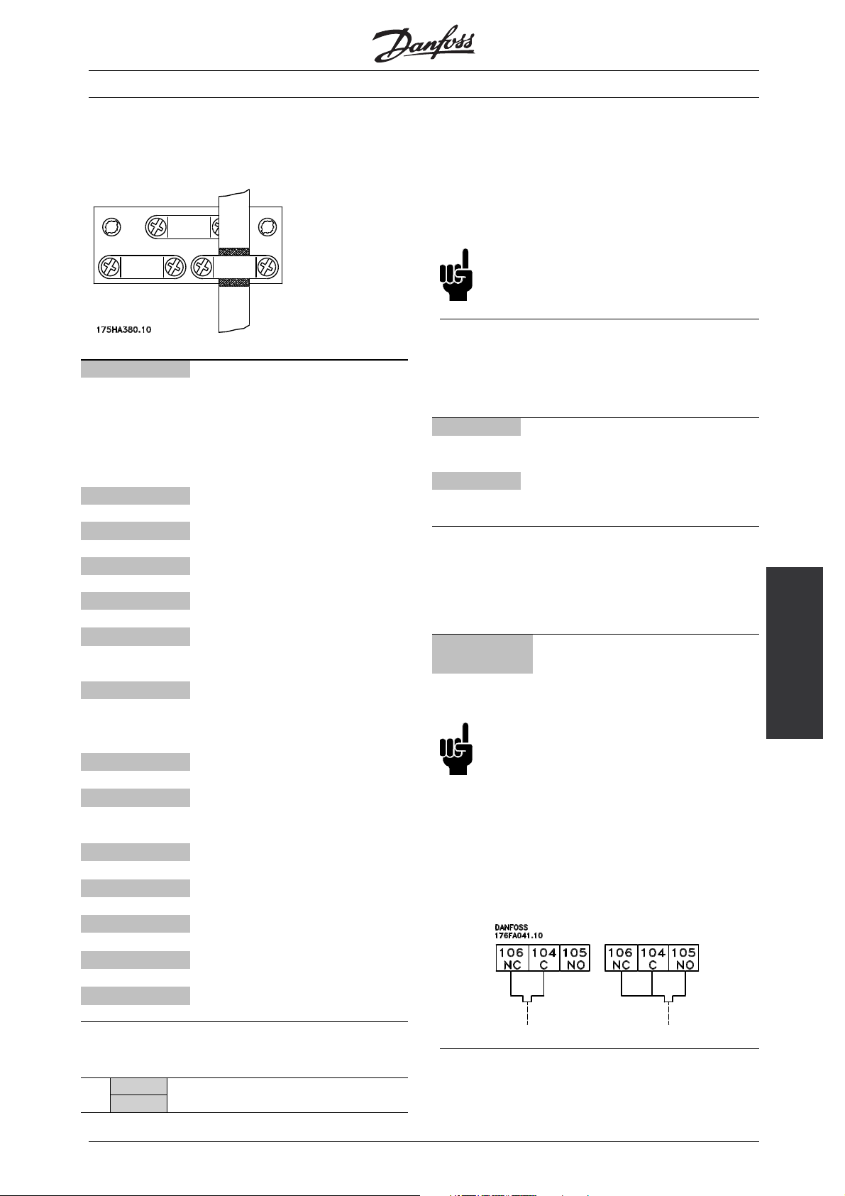
■Installation of Brake Resistor Temperature Switch
Torque: 0.5-0.6 Nm
Screw size: M3
No. Function
106, 104,
Brake resistor temperature switch.
105
NB!:
This function is only available on VLT
5072-5202 400-500 V.
If the temperature of the brake resistor gets too high and
the terminal switch drops out, the frequency converter
will stop braking. The motor will start coasting.
A terminal switch must be installed that can either be
‘normally closed’ or ‘normally open’. If this function is
not used, 106 and 104 must be short-circuited together.
Installation
■Brake Connection
No. 81 82 Brake resistor
R- R+ terminals
MG.50.N4.02 - VLT is a registered Danfoss trademark
29
Page 31

VLT® 5000 Crane
■EMC-Correct Electrical Installation
General points to be observed to ensure
EMC-correct electrical installation.
- It is important to ensure good electrical contact from
the installation plate through the installation screws
to the metal cabinet of the frequency converter.
- Use toothed discs and galvanic conductive
- Use only screened/armoured motor cables and
screened/armoured control cables.
- Connect the screen to earth at both ends.
installation plates.
- Do not use unscreened/unarmoured motor
cables in the installation cabinets.
- Avoid installation with twisted screen ends (pigtails),
since this ruins the screening effect at high
frequencies. Use cable clamps instead.
■Tightening-up Torques and Screw Sizes
Mains terminals Nos 91, 92, 93
The table shows the torque required when fitting
terminals to the frequency converter. For VLT
5042-5302 400-500 V, the cables must be fastened
Motor terminals Nos 96, 97, 98
with screws. For VLT 5122-5500 400-500 V, the
cables must be fastened with bolts.
These figures apply to the following terminals:
400-500 V
5042 IP20 3 M5 4 mm Allen wrench
3)
5042
5052-5062 6 M6 5 mm Allen wrench
5072-5102 IP20 15 M6 6 mm Allen wrench
5122-5302
4)
IP54 3 M5 4 mm Allen wrench
IP54
2)
24 M8 8 mm Allen wrench
19 M10 bolt
Earth terminal No 94, 95, 99
Brake resistor terminals 81, 82
Loadsharing 88, 89
L1, L2, L3
U, V, W
1) Brake terminals: 3,0 Nm, Nut: M6
2) Brake and loadsharing: 14 Nm, M6 Allen screw
3) IP54 with RFI - Line terminals 6Nm, Screw: M6 - 5 mm Allen wrench
4) Loadshare and brake terminals: 9,5 Nm; Bolt M8
5) Brake terminals: 11,3 Nm; Bolt M8
■High Voltage Test
A high voltage test can be carried out by shortcircuitingterminalsU,V,W,L
1,L2
and L3and
energizing by max. 2.15 kV DC for one second
between this short-circuit and the chassis.
■Extra Protection (RCD)
ELCB (Earth Leakage Circuit Breaker) relays,
multiple protective earthing or earthing can be
used as extra protection, provided that local
safety regulations are complied with. In case
of an earth fault, a DC content may develop in
NB!:
the faulty current. If ELCB relays are used:
The RFI switch must be closed (position ON)
when high voltage tests are carried out.
- Local regulations must be complied with
- Suitable for protecting equipment with a DC content
■Motor Thermal Protection
The electronic thermal protection function in
UL-approved frequency converters has received
the UL-approval for single motor protection when
in the faulty current (3-phase bridge rectifier)
- Suitable for a pulse-shaped, brief discharge
on power-up
- Suitable for a high leakage current.
parameter 128 has been set for ETR Trip and
parameter 105 has been programmed to the rated
motor current (see motor nameplate).
NB!:
Never use an RCD (ELCB relay), type A, as it
is not suitable for DC faulty currents.
30
MG.50.N4.02 - VLT is a registered Danfoss trademark
Page 32

■Switches 1-4:
The dipswitch is located on the control card.
It is used for serial communication, terminals 68 and 69.
The switching position shown is the factory setting.
Switch 1 has no function.
Switches 2 and 3 are used for terminating an RS
485 interface, serial communication.
Switch 4 is used for separating the common potential
for the internal 24 V DC supply from the common
potential of the external 24 V DC supply.
NB!:
Please note that when Switch 4 is in position
"OFF", the external 24 V DC supply is galvanic
isolated from the frequency converter.
VLT® 5000 Crane
■Electrical Installation, Enclosures
Compact IP 20 VLT 5042-5102, 400-500 V
Installation
MG.50.N4.02 - VLT is a registered Danfoss trademark
Compact IP 20 VLT 5042-5062, 400-500 V
31
Page 33

Compact IP 20 VLT 5072-5102, 400-500 V
VLT® 5000 Crane
Compact IP 00 without disconnect and fuse
VLT 5202-5302 400-500 V
Compact IP 00 without disconnect and fuse
VLT 5122-5302 400-500 V
32
MG.50.N4.02 - VLT is a registered Danfoss trademark
Page 34

■RFI switch
ains supply isolated from earth:
M
If the frequency converter is supplied from an isolated
mainssource(ITmains),theRFIswitchcanbe
turned off (OFF). In OFF position, the internal RFI
capacities (filter capacitors) between the chassis and
the intermediate circuit are cut off to avoid damage
to the intermediate circuit and to reduce the earth
capacity currents (according to IEC 61800-3).
NB!:
TheRFIswitchisnottobeoperatedwith
mains connected to the unit. Check that
the mains supply has been disconnected
before operating the RFI switch.
NB!:
Open RFI switch is only allowed at factory
set switching frequencies.
NB!:
The RFI switch disconnects the capacitors
galvanically to ground.
VLT® 5000 Crane
P
osition of RFI switches
The red switches are operated by means of e.g. a
screwdriver. They are set in the OFF position when
they are pulled out and in ON position when they are
pushed in (see drawing below). Factory setting is ON.
Mains supply connected to earth:
The RFI switch must be in ON position in order for the
frequency converter to comply with the EMC-standard.
Compact IP 20/NEMA 1
VLT 5042 - 5062 400 - 500 V
Installation
MG.50.N4.02 - VLT is a registered Danfoss trademark
33
Page 35

VLT® 5000 Crane
■Use of EMC compliant cables
In order to comply with requirements for EMC immunity
of the control cables and EMC emissions from the
motor cables screened/armoured cables must be used.
The ability of a cable to reduce the amount of ingoing
and outgoing radiation of electric noise depends
on the transfer impedance (Z
). The screen of a
T
cable is normally designed to reduce the transfer of
electric noise, and a screen with a lower Z
effective than a screen with a higher Z
is rarely stated by cable manufacturers, but it
Z
T
is often possible to estimate Z
by looking at and
T
is more
T
.
T
assessing the physical design of the cable.
Z
can be assessed on the basis of the following factors:
T
- the contact resistance between the individual
screen conductors.
- Screen coverage, i.e. the physical area of the
cable covered by the screen. Is often stated as a
percentage and should be no less than 85%.
- The screen type, i.e. braided or twisted pattern. A
braided pattern or closed pipe is recommended.
34
MG.50.N4.02 - VLT is a registered Danfoss trademark
Page 36
VLT® 5000 Crane
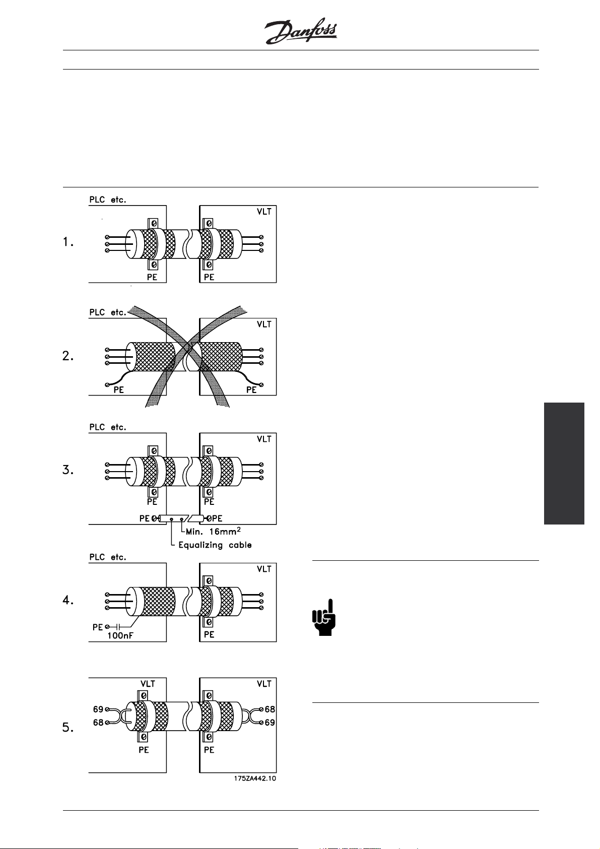
■Earthing of Braided Screened/armoured
Control Cables
Generally speaking, control cables must be braided screened/armoured and the screen must be connected
by means of a cable clamp at both ends to the metal cabinet of the unit.
The drawing below indicates how correct earthing is carried out and what to be done if in doubt.
1. Correct earthing
Control cables and cables for serial
communication must be fitted with cable
clamps at both ends to ensure the best
possible electrical contact.
2. Wrong earthing
Do not use twisted cable ends (pigtails), since these increase the screen
impedance at high frequencies.
3. Protection with respect to earth potential
between PLC and frequency converter
If the earth potential between the frequency
converter and the PLC (etc.) is different, electric
noise may occur that will disturb the whole system.
This problem can be solved by fitting an equalising
cable, to be placed next to the control cable.
Minimum cable cross-section: 16 mm
4. For 50/60 Hz earth loops
If very long control cables are used,
50/60 Hz earth loops may occur. This problem can
be solved by connecting one end of the screen to
earth via a 100nF capacitor (keeping leads short).
5. Cables for serial communication
It is recommended to use twisted-pair
cables to reduce the differential mode interference
between the conductors.
2
Installation
MG.50.N4.02 - VLT is a registered Danfoss trademark
■Safety Earthing
NB!:
The frequency converter has a leakage
current and must be earthed appropriately
for safety reasons. Use earth terminal,
which enables reinforced earthing.
Apply national safety regulations.
35
Page 37
VLT® 5000 Crane
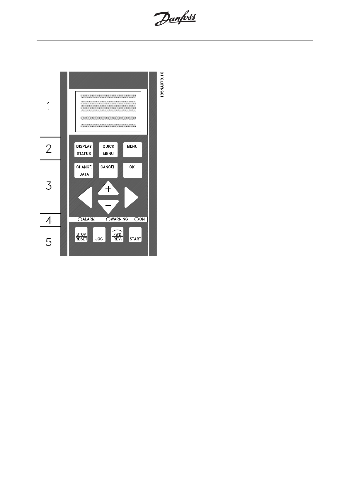
■Control Panel
the correct password in parameter 650 and if in
parameter 018 Not Locked [0] is selected.
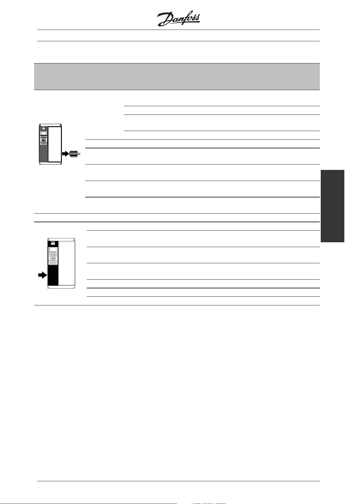
The VLT 5000 Crane can be combined with an LCP
control unit (Local Control Panel) which makes up a
complete interface for operation and programming
of the frequency converter. The LCP control panel
can be installed up to 3 metres away from the
frequency converter, eg. on a front panel, by
means of the additional mounting kit.
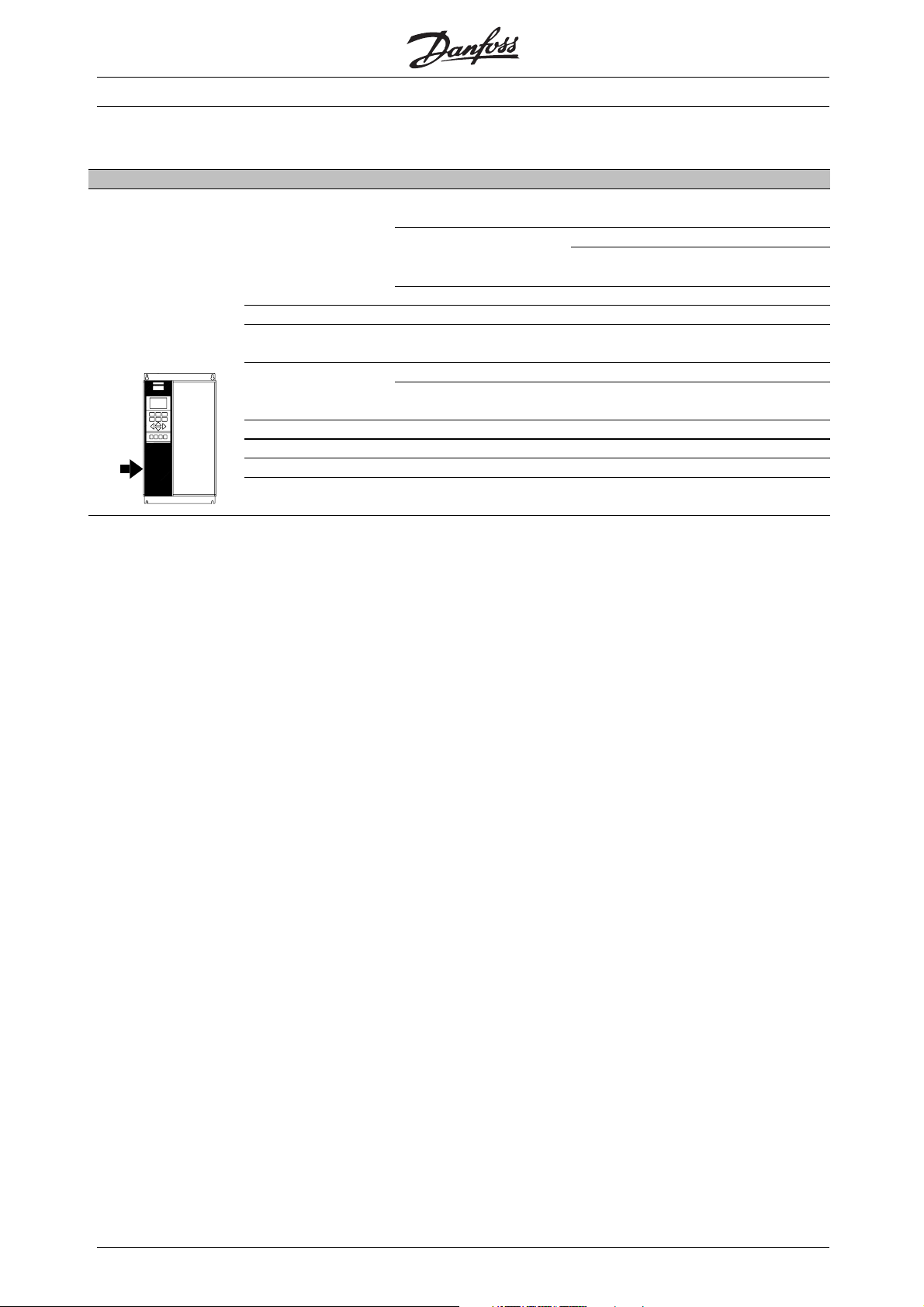
The control panel is divided into five functional groups:
1. Display.
2. Keys used to change the display function.
3. Keys used to change the programme parameters.
4. Indicator lamps.
5. Local control keys.
Alldataisdisplayedviaa4-linealphanumeric
display, which during normal operation will be able
to continuously display 4 items of operating data
and 3 operating modes. During programming all
information needed for quick, effective parameter
setup of the frequency converter will be displayed.
As a supplement to the display there are three
indicator lamps for voltage indication (ON), warning
(WARNING) and alarm (ALARM) respectively. All
frequency converter parameter Setups can be changed
immediately from the control panel, after entering
✭ = factory setting. () = display text [] = value for use in communication via serial communication port
36
MG.50.N4.02 - VLT is a registered Danfoss trademark
Page 38
VLT® 5000 Crane
■Display
The LCD-display has back lighting and a total of
4 alpha-numeric lines including a box showing the
direction of rotation (arrow) and the chosen set-up as
well as the set-up in which programming is taking place.
1st line
2nd line
3rd line
4th line
1st line shows up to 3 measurements continuously in
normal operating status or a text explaining the 2nd line.
2nd line shows a measurement with related
unit continuously, regardless of status (except
in case of an alarm/warning).
3rd line is normally blank and is used in the
menu mode to show the selected parameter
group number and name
12345678901234567890
SETUP
12345678
1
12345678901234567890
12345678901234567890
VAR 1.1 VAR 1.2 VAR 1.3
VAR 2
175ZA443.10
STATUS
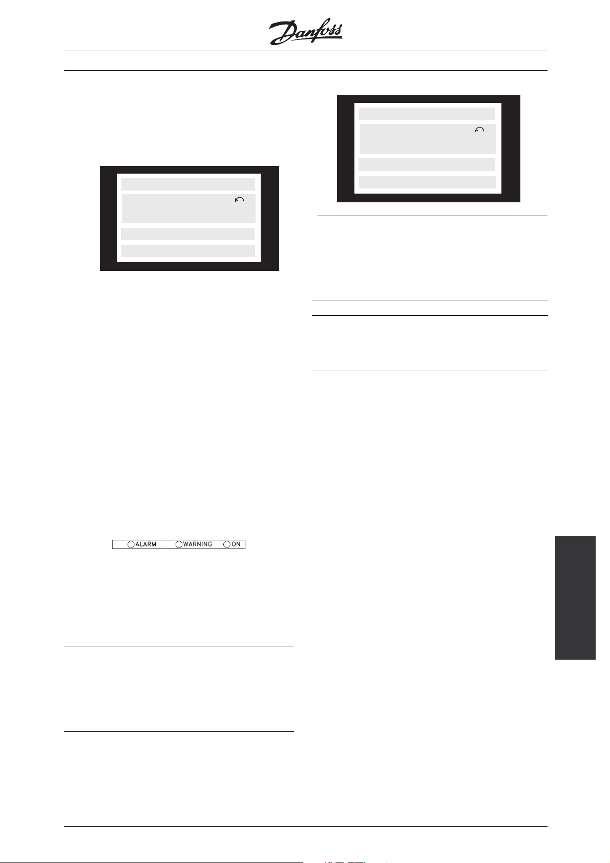
■Display Mode - Selection of Read-Out State
There are three options in connection with the
choice of read-out state in the Display mode - I, II
and III. The choice of read-out state determines the
number of operating variables read out.
Read-out state: I: II: III:
Line 1 Description
for operating
variable in line 2
The table below gives the units linked to the variables
in the first and second line of the display.
Data value for
3operating
variables in line
1
195NA113.10
SETUP
1
Description for
3operating
variables in line
1
4th line is used in operating status for showing a
status text or in data change mode for showing the
mode or value of the selected parameter.
An arrow indicates the direction of the motor rotation.
■LEDs
At the bottom of the control panel is a red alarm
LED, a yellow LED and a green voltage LED.
red yellow green
If certain threshold values are exceeded, the alarm
and/or warning LED lights up concurrently with a
status and alarm text on the control panel.
■Display Read-Out State
The display read-out state can be varied - see the list
below - depending on whether the frequency converter
is in normal operation or is being programmed.
Panel
LCP - Local Control
■Display Mode
In normal operation, up to 4 different operating
variables can be indicated continuously: 1.1 and 1.2
and 1.3 and 2, and in line 4 the present operating
status or alarms and warnings that have arisen.
= factory setting. () = display text [] = value for use in communication via serial communication port
✭
MG.50.N4.02 - VLT is a registered Danfoss trademark
37
Page 39

VLT® 5000 Crane
Operating variable: Unit:
Reference [%]
Reference [unit]
Feedback [unit]
Frequency [Hz]
Speed RPM [rpm]
Current [A]
To rq ue [ %]
Power [kW]
Power [HP]
Output energy [kWh]
Motor voltage [V]
DC-link voltage [V]
Motor ETR value [%]
Inverter ETR value [%]
Hours run [Hours]
Digital input [Bin]
Input status, analogue terminal 53 [V]
Input status, analogue terminal 58 [mA]
Input status, analogue terminal 60 [mA]
Exter nal reference [%]
Status word [Hex]
Brake energy/2 min. [kW]
Brake energy/sec. [kW]
Heat sink temp. [ºC]
Alarm word [Hex]
Control word [Hex]
Warning word 1 [Hex]
Extended status word [Hex]
Operating variables 1.1, 1.2 and 1.3 in the first line,
and operating variable 2 in the second line are selected
via parameter 009, 010, 011 and 012.
normal operation another variable can immediately
be read out by using the [+/-] keys.
• Read-out state II:
Switching between read-out states I and II is effected
by pressing the [DISPLAY / STATUS] key.
24.3% 30.2% 13.8A
50.0 Hz
MOTOR IS RUNNING
In this state, data values for four operating values
are shown at the same time, giving the related
unit, cf. table. In the example, Reference, Torque,
Current and Frequency are selected as variables
in the first and second line.
• Read-out state III:
This read-out state can be held as long as the
[DISPLAY/STATUS] key is pressed. When the
key is released, the system switches back to
Read-out state II, unless the key is pressed for
less that approx. 1 sec., in which case the system
always reverts to Read-out state I.
REF% TORQUE CURR A
SETUP
50.0 Hz
MOTOR IS RUNNING
1
• Read-out state I:
This read-out state is standard after starting
up or after initialisation.
This is where parameter names and
variables in the first and second line are given operating variable 2 remains unchanged.
FREQUENCY
50.0 Hz
MOTOR IS RUNNING
Line 2 gives the data value of an operating variable with
related unit, and line 1 provides a text which explains
line 2, cf. table. In the example, Frequency has
been selected as variable via parameter 009. During
✭ = factory setting. () = display text [] = value for use in communication via serial communication port
38
MG.50.N4.02 - VLT is a registered Danfoss trademark
units for operating
Page 40

■Parameter programming
Menu mode is started by pressing the [MENU] key,
which produces the following readout on the display:
FREQUENCY
50.0 Hz
0 KEYB.&DISPLAY
VLT® 5000 Crane
Changing data
Regardless of whether a parameter has been
selected under the Quick menu or the Menu mode,
the procedure for changing data will be the same.
Pressing the [CHANGE DATA] key gives access
to changing the selected parameter, following
which the underlining in line 4 will flash on the
display. The procedure for changing data depends
on whether the selected parameter represents a
numerical data value or a text value.
Line 3 on the display shows the parameter
group number and name.
In Menu mode, the parameters are divided
into groups. Selection of parameter group is
effected using the [< >] keys.
The following parameter groups will be accessible:
Group no. Parameter group
0xx Operation & Display
1xx Load & Motor
2xx References & Limits
3xx Inputs & Outputs
4xx Special functions
5xx Serial communication
6xx Technical functions
7xx Crane functions
When the required parameter group has been
selected, each parameter can be chosen by
means of the [+ / -] keys:
FREQUENCY
Changing a data value
If the selected parameter is a text value, the text value
is changed by means of the [+ / -] keys.
FREQUENCY
50.0 Hz
001 LANGUAGE
ENGLISH
The bottom display line will show the value that will be
entered (saved) when acknowledgment is given [OK].
Change of numeric data value
If the selected parameter is represented by a numerical
data value, a digit is first chosen using the [< >] keys.
FREQUENCY
SETUP
50.0 Hz
130 START FREQUENCY
09.0 HZ
1
Panel
50.0 Hz
001 LANGUAGE
ENGLISH
The3rdlineofthedisplayshowstheparameter
number and name, while the status/value of the
selected parameter is shown in line 4.
MG.50.N4.02 - VLT is a registered Danfoss trademark
The selected digit can then be changed infinitely
variably using the [+ / -] keys:
FREQUENCY
SETUP
50.0 Hz
1
130 START FREQUENCY
10.0 HZ
LCP - Local Control
39
Page 41

VLT® 5000 Crane
The chosen digit is indicated by the digit flashing. The
bottom display line shows the data value that will be
entered (saved) when signing off with [OK].
■Manual initialization
Manual initialization is performed as follows:
Cut mains. Hold the [DISPLAY STATUS] + [CHANGE
DATA] + [OK] keys down, and simultaneously
reconnect the mains. Release the keys; the frequency
converter has now been programmed for the
factory setting. The following parameters are not
reset during manual initialization:
- par. 600 Operating hours
- par. 601 Hours run
- par. 602 kWh counter
- par. 603 Number of power-ups
- par. 604 Number of overtemperatures
- par. 605 Number of overvoltages
■Changing of datavalue, step-by-step
Certain parameters can be changed step by step
or infinitely variably. This applies to Motor power
(parameter 102), Motor voltage (parameter 103)
and Motor frequency (parameter 104).
This means that the parameters are changed
bothasagroupofnumericdatavaluesandas
numeric data values infinitely variably.
■Infinitely Variable Change of NumericData Value
If the chosen parameter represents a numeric data
value, a digit is first selected by means of the [<>] keys.
FREQUENCY
SETUP
50.0 HZ
1
102 MOTOR POWER
0.37 KW
Then the chosen digit is changed infinitely variably
by means of the [+/-] keys:
FREQUENCY
SETUP
50.0 HZ
102 MOTOR POWER
1
SETUP
1
0.55 KW
The chosen digit is indicated by the digit flashing. The
bottom display line shows the data value that will be
entered (saved) when signi
40
ng off with [OK]
MG.50.N4.02 - VLT is a registered Danfoss trademark
Page 42

■Menu Structure
DISPLAY MODE
VAR 1.1 VAR 1.2 VAR 1.3
▲
VAR 2
STATUS
VLT® 5000 Crane
▲
▲
MENU MODE
FREQUENCY
1500 RPM
0 KEYB.&DISPLAY
Choice of
parameter
DATA MODE
FREQUENCY
1500 RPM
001 LANGUAGE
ENGLISH
▲
Choice of
group
▲
QUICK MENU MODE
QUICK MENU 1 OF 13
▲
▲▲
1500 RPM
001 LANGUAGE
ENGLISH
▲
DATA CHANGE MODE
FREQUENCY
1500 RPM
001 LANGUAGE
ENGLISH
175ZA721.10
✭ = factory setting. () = display text [] = value for use in communication via serial communication port
MG.50.N4.02 - VLT is a registered Danfoss trademark
Choice of
data value
DATA CHANGE MODE
QUICK MENU 1 OF 13
1500 RPM
001 LANGUAGE
ENGLISH
Panel
LCP - Local Control
41
Page 43

VLT® 5000 Crane
■General Advice on Programming
On the following pages the control keys for parameter
set-up and the local control keys will be explained.
First, however, please draw attention to the difference
between the [+]/[-] keys and the [<]/[>] keys.
The [+]/[-] keys are used for:
• Changing parameter numbers within a
parameter group
• Changing parameter values
The [<]/[>] keys are used for:
• Shifting between parameter groups
• Moving the cursor when changing numeric values
For further details on the parameter groups, please
refer to the table in Parameter Programming.
Example:
The configuration mode in parameter 100 is to
be set to SPEED CLOSED LOOP.
1. Press Menu to get access to the parameters
2. Press the [>] key to enter parameter group 100
3. Press [Change Data]
4. Press the [+] key twice to select the data value
[1] for SPEED CLOSED LOOP
5. Press [OK]
6. The parameter is now set
■Control keys for parameter Setup
The control keys are divided into functions, in such a
way that the keys between the display and the indicator
lamps are used for parameter Setup, including selection
of the display’s view mode during normal operation.
[DISPLAY/STATUS] is used to select the display’s
view mode or to change back to Display mode
from either Quick Menu or Menu mode.
[QUICK MENU] provides access to the parameters
used in the Quick Menu. It is possible to switch
between Quick Menu and Menu mode.
[MENU] gives access to all parameters. It is possible
to switch between Menu mode and Quick Menu.
[CHANGE DATA] is used to change a parameter that
has been selected either in Menu mode or Quick Menu.
■Password Protection
To protect against unintended change of sensitive
parameters, eg. motor parameters, some of the
parameters are protected by a password. There
are three levels of protection, for which two of the
levels are protected by a password. The password
protection is only accessable from the LCP, not from
the serial bus communication. This means that all
parameters are accessable from the bus eventhough
they may be protected from the LCP.
The three levels are the following:
• Level 0: Danfoss service (not accessable)
• Level 1: Commissioning (110775)
• Level 2: Normal operation (000002)
NB!:
NOTE that level 1 and level 2 passwords must
be re-entered after each power-up!
For further information on password protection
see Parameter 650.
[CANCEL] is used if a change to the selected
parameter is not to be implemented.
[OK] is used to confirm a change to a
selected parameter.
[+ / -] are used for selecting parameters and
for changing parameter values.
These keys are also used in Display mode to switch
between the readouts of operating variables.
[< >] are used for selecting parameter group and to
move the cursor when changing a numerical value.
✭ = factory setting. () = display text [] = value for use in communication via serial communication port
42
MG.50.N4.02 - VLT is a registered Danfoss trademark
Page 44

■Local control
[STOP/RESET] is used for stopping the motor
connected or for resetting the frequency converter
after a drop-out (trip). Can be set to active or
inactive via parameter 014 Local stop.
If stop is activated Display line 2 will flash.
NB!:
If an external stop function is not selected and
the [STOP/RESET] key is set to inactive, the
motor can only be stopped by disconnecting
the voltage to the motor or the frequency converter.
VLT® 5000 Crane
[FWD / REV] changes the direction of rotation of
the motor, which is indicated by means of the arrow
on the display. Can be set to active or inactive via
parameter 016 Local reversing. The [FWD/REV] key
is only active when parameter 002 Local/remote
operation is set to Local control.
NB!:
Note that the fwd/rev function is not active
in crane profile. The function only functions
if the VLT is programmed to run as a normal
VLT 5000 (see parameter 512).
[START] is used to start the frequency converter. Is
always active, but cannot override a stop command.
NB!:
If the local control keys are set to inactive,
these will both become active when the
frequency converter is set to Local control
and Remote control via parameter 002 Local/remote
operation, with the exception of [FWD/REV], which
is only active in Local control.
[JOG] overrides the output frequency to a preset
frequency while the key is pressed down.
NB!:
The Jog function is not available in crane profile.
If the VLT 5000 Crane is programmed to run
as a normal VLT 5000 (see parameter 512),
the Jog function will, however, be available.
✭ = factory setting. () = display text [] = value for use in communication via serial communication port
MG.50.N4.02 - VLT is a registered Danfoss trademark
Programming
43
Page 45

VLT® 5000 Crane
PNU Parameter Range Factory setting Changes Unit Conversion Data Protection
#
description
0xx
Operation and display
001 Language English Yes 0 0 5 2
002 Operation site Remote control Yes 0 0 5 2
003 Local reference 0Yes0-342
007 LCP copy No copy No 0 0 5 0
009 Display linie 2 Speed [RPM] Yes 0 0 5 2
010 Displayline1.1 Reference [%] Yes 0 0 5 2
011 Displayline1.2 Motor current [A] Yes 0 0 5 2
012 Displayline1.3 Power [kW] Yes 0 0 5 2
014 LCP stop Enable Yes 0 0 5 1
015 LCP jogging Disable Yes 0 0 5 1
016 LCP reversing Disable Yes 0 0 5 1
017 LCP res et of trip Enable Yes 0 0 5 2
018 Lock for data c hange Not locked Yes 0 0 5 1
1xx Motor and Load
100 Configuration Speed control,
closed loop
102 Motor power 0.18 - 500 kW Depends on unit No 9 1 6 1
103 Motor voltage 200 - 500 V Depends on unit No 21 0 6 1
104 Motor frequency 24 - 1000Hz Depends on unit No 28 0 6 1
105 Motor current 0.01 - 1
106 Rated motor speed 100 - 60000
122 Function at stop Coast Yes 0 0 5 1
124 DC-hold current 0 - 100% 50% Yes 27 0 6 1
128 Motor thermal
protection
150 Stator resistance Depends on unit No 23 -4 7 1
151 Rotor resistance Depends on unit No 23 -4 7 1
152 Stator leakage Depends on unit No 23 -3 7 1
153 Rotor leakage Depends on unit No 23 -3 7 1
154 Main reactance Depends on unit No 23 -3 7 1
155 Rotor inertia Depends on unit No 0 -4 7 1
156 Pole number 4No0051
157 Field weakening
speed
158 Ironloss resistance 1 - 10000 10000 No 23 0 6 1
VLT,MAX
rpm
0 - 6000RPM Depends on unit No 11 67 6 1
Depends on unit No 22 -2 7 1
Depends on unit No 11 67 6 1
No protection Yes 0 0 5 1
during
operation
No 0 0 5 2
index index type level
✭ = factory setting. () = display text [] = value for use in communication via serial communication port
44
MG.50.N4.02 - VLT is a registered Danfoss trademark
Page 46

VLT® 5000 Crane
PNU Parameter Range Factory setting Changes Unit Conversion Data Protection
#
2xx
202 O u tput speed high
205 Maximum reference 0.001-
207 Ramp-up time 1 0.05 - 3600 0.85 sec. Yes 4 -2 7 1
208 Ramp-down time 1 0.05 - 3600 0.85 sec. Yes 4 -2 7 1
211 Jogramptime 0.05 - 3600 0.85 sec. Yes 4 -2 7 1
212 Quick stop
213 Jog speed 0 - 4500 RPM 200 RPM Yes 11 67 6 2
221 Torque limit motor
222 Torque limit
234 Missingmotorphase Enable Yes 0 0 5 1
235 P h ase loss monitor Enable No 0 0 5 1
236 Low speed ref.
description
References & Limits
limit
ramp-down time
mode
generator operation
current
during
operation
0-5000 RPM 3000 RPM Yes 11 67 6 1
3000 Yes 0 -3 4 1
100.000
0.05 - 3600 0.85 sec. Yes 4 -2 7 1
0.0% - 170% 160 % Yes 24 -1 6 1
0.0% - 170% 160 % Yes 24 -1 6 1
0 - 160% 50% Yes 27 0 5 1
index index type level
Changes during operation:
"Yes" means that the parameter can be changed,
while the frequency converter is in operation. "No"
means that the frequency converter must be stopped
before a change can be made.
C
onversion index/unit index:
This number refers to a conversion figure to
be used when writing or reading by means of
a frequency converter. Please refer to Serial
Communication in Appendix.
= factory setting. () = display text [] = value for use in communication via serial communication port
✭
MG.50.N4.02 - VLT is a registered Danfoss trademark
Programming
45
Page 47

VLT® 5000 Crane
PNU Parameter Range Factory setting Changes Unit Conversion Data Protection
#
3xx
300 Terminal 16, input Master/slave Yes 0 0 5 1
301 Terminal 17, input Positioning Yes 0 0 5 1
302 Terminal 18 Start,
303 Terminal 19, input Start hoisting Yes 0 0 5 1
304 Terminal 27, input Crane Q stop inv. Yes 0 0 5 1
305 Terminal 29, input Gear choice Yes 0 0 5 1
306 Terminal 32, input Load contact 1 Yes 0 0 5 1
307 Terminal 33, input Load contact 2 Yes 0 0 5 1
308 Terminal 53,
309 Terminal 53, min.
310 Terminal 53, max.
314 Terminal 60,
315 Terminal 60, min.
316 Terminal 60, max.
317 Time out 0 sec 0 sec. Yes 4 0 5 1
318 Function after time
319 Terminal 42, output No operation Yes 0 0 5 1
321 Terminal 45, output No operation Yes 0 0 5 1
323 Relay 01, output Mechanical brake
324 Relay 01, ON delay 0.00 - 600
325 Relay 01, OFF delay 0.00 - 600
326 Relay 04, output Unit ready Yes 0 0 5 1
329 Encoder feedback
341 Terminal 46, digital
352 Terminal 58,
353 Terminal 58, min.
354 Terminal 50, max.
355 Terminal 26, digital
description
Inputs and outputs
input
analogue input
voltage
scaling
scaling
analogue input
current
scaling
scaling
out
pulse/rev.
signal output
analogue input
current
scaling
scaling
signal output
during
operation
Start lowering Yes 0 0 5 1
Reference Yes 0 0 5 1
0.0 - 10.0 V 0.0 V Yes 21 -1 5 1
0.0 - 10.0 V 10.0 V Yes 21 -1 5 1
Reference Yes 0 0 5 1
0.0 - 20.0mA 4.0 mA Yes 22 -4 5 1
0.0 - 20.0mA 20.0 mA Yes 22 -4 5 1
Off Yes 0 0 5 1
Yes 0 0 5 1
control
0.00 sec. Yes 4 -2 6 1
sec.
0.00 sec. Yes 4 -2 6 1
sec.
1024
pulses/rev.
0.0 - 20.0 mA 4 mA Yes 22 -4 5 1
0.0 - 20.0 mA 20 mA Yes 22 -4 5 1
1024 pulses/rev. No 0 0 6 1
No operation Yes 0 0 5 1
Reference Yes 0 0 5 1
No operation Yes 0 0 5 1
index index type level
✭ = factory setting. () = display text [] = value for use in communication via serial communication port
46
MG.50.N4.02 - VLT is a registered Danfoss trademark
Page 48

VLT® 5000 Crane
PNU Parameter Range Factory setting Changes Unit Conversion Data Protection
#
description
4xx
Application functions
400 Brake function/over-
voltage control
401 Brake resistor, ohm 0 - 500 Depends on unit Yes 23 -1 6 1
402 Brake power limit, kW 0 - 1000kW 0 kW Yes 9 2 6 1
403 Power monitoring Warning Yes 00 51
404 Brake check Off Yes 00 51
405 Reset mode Manual reset Yes 0 0 5 1
421 Speed PID filter time 1 - 20 ms 3.2 ms Yes 4 -4 6 1
Resistor Yes 0 0 5 1
during
operation
index index type level
Parameter group 5xx, see serial communication!
NB!:
In parameter 512 it is possible to shift between
crane profile and FC profile!
PNU Parameter Factory setting Changes Unit Conversion Data Protection
#
6xx
600 O peration data: Operating hours No 4 74 7 2
601 Op eration Data: Running hours No 4 74 7 2
602 Op eration Data: kWh coun ter No 8 2 7 2
603 Op eration Data: Power ups No 0 0 6 2
604 Op eration Data: Over tem ps No 0 0 6 2
605 Op eration Data: Over volts No 0 0 6 2
615 Fault log: Error code No 0 0 5 2
616 Fault log: Time No 0 -1 7 2
617 Fault log: Value No 0 0 3 2
618 R eset of kW h counter Do not reset Yes 0 0 5 1
619 R eset of hours-run counter Do not reset Yes 0 0 5 1
620 Op erating mode Normal function Normal operation Yes 0 0 5 1
621 Type plate: VLT type No 0 0 9 2
622 Type plate: Power section No 0 0 9 2
623 Type plate: VLT ordering number No 0 0 9 2
624 Type plate: Software version
625 Type plate: LCP ID no. No 0 0 9 2
626 Type plate: Parameter database
627 Type plate: PU database ID no No 0 0 9 2
628 Type plate: Application option
629 Type plate: Application ordering
630 Type plate: C om munication type No 0 0 9 2
631 Type plate: Communication
639 Flash test On Yes 0 0 5 1
650 P rotection level Yes 0 0 7 2
description
Service functions
number
ID no.
type
number
ordering number
during
operation
No 0 0 9 2
No 0 -2 9 2
No 0 0 9 2
No 0 0 9 2
No 0 0 9 2
index index type level
✭ = factory setting. () = display text [] = value for use in communication via serial communication port
MG.50.N4.02 - VLT is a registered Danfoss trademark
Programming
47
Page 49

VLT® 5000 Crane
PNU Parameter Range Factory setting Changes Unit Conversion Data Protection
#
7xx
701 Load low 0 - 5000RPM 2500RPM No 11 67 6 1
702 Load high 0 - 1250RPM 1250RPM No 11 67 6 1
703 Load monitoring Enable No 0 0 5 1
704 L ow speed at error 5 - 200RPM 50 RPM No 11 67 5 1
705 Brake on RPM 0 - 50RPM 20 RPM No 11 67 5 1
707 Hoist direction Forward No 0 0 5 1
708 S tart torque 0 - 170% 100% No 27 0 5 1
709 R amp torque 0.2-2sec. 0.2sec. No 4 -1 5 1
712 B rake monitoring Enable Yes 0 0 5 1
713 Derating lowering 0.6 - 1 0.8 No 0 -2 5 1
714 D erating hoisting 0.6 - 1 1 No 0 -2 5 1
715 Mech. brake on
716 Mech. brake off
718 Encoder
720 Drum inertia 1 0 - 1 Depends on unit No 0 -4 6 1
721 G ear ratio 1 0 - 200 Depends on unit No 0 -2 6 1
722 G ear inertia 1 0 - 1 Depends on unit No 0 -4 6 1
723 Mean radius 1 0 - 2 Depends on unit No 0 -3 6 1
724 Drum inertia 2 0 - 1 Depends on unit No 0 -4 6 1
725 G ear ratio 2 0 - 200 Depends on unit No 0 -2 6 1
726 G ear inertia 2 0 - 1 Depends on unit No 0 -4 6 1
727 Mean radius 2 0 - 2 Depends on unit No 0 -3 6 1
740 Power limitfunction Constant power No 0 0 5 1
741 Mechanical speed
742 Power at N1 Depends on unit No 9 1 6 1
743 Mechanical speed
744 Power at N2 Depends on unit No 9 1 6 1
745 Mechanical speed at
746 Power at N3 Depends on unit No 9 1 6 1
747 Mechanical speed at
748 Power at N4 Depends on unit No 9 1 6 1
749 Mechanical speed
750 Power at N5 Depends on unit No 9 1 6 1
751 Mechanical speed
752 Power at N6 Depends on unit No 9 1 6 1
753 Mechanical speed
754 Power at N7 Depends on unit No 9 1 6 1
755 Power Loss N1 Depends on unit No 9 1 6 1
756 Power Loss N2 Depends on unit No 9 1 6 1
757 Power Loss N3 Depends on unit No 9 1 6 1
758 Power Loss N4 Depends on unit No 9 1 6 1
759 Power Loss N5 Depends on unit No 9 1 6 1
760 Power Loss N6 Depends on unit No 9 1 6 1
761 Power Loss N7 Depends on unit No 9 1 6 1
description
Crane functions
delay
delay
monitoring
N1
at N2
N3
N4
N5
N6
N7
during
operation
0,1 - 20 sec. 0,5 sec. Yes 4 -1 5 1
0,1 - 20 sec. 0,5 sec. Yes 4 -1 5 1
Enable No 0 0 5 1
Depends on unit No 11 0 6 1
Depends on unit No 11 67 6 1
Depends on unit No 11 67 6 1
Depends on unit No 11 67 6 1
Depends on unit No 11 67 6 1
Depends on unit No 11 67 6 1
Depends on unit No 11 67 6 1
index index type level
✭ = factory setting. () = display text [] = value for use in communication via serial communication port
48
MG.50.N4.02 - VLT is a registered Danfoss trademark
Page 50

■Parameter survey
VLT® 5000 Crane
✭ = factory setting. () = display text [] = value for use in communication via serial communication port
MG.50.N4.02 - VLT is a registered Danfoss trademark
Programming
49
Page 51
VLT® 5000 Crane
■Operation & Display
001 LANGUAGE
Value:
✭English (ENGLISH)
German (DEUTSCH)
French (FRANCAIS)
Spanish (ESPANOL)
Italian (ITALIANO)
Function:
The purpose of this parameter is to set the
language to be shown in the display whenever
the LCP control unit is connected.
002 OPERATION SITE
Value:
✭Remote operation (REMOTE)
Local operation (LOCAL)
Function:
The purpose of this parameter is to set the control of
the frequency converter to eitherRemote operation [0]
or Local operation [1]. See also parameter 013 Local
control if Local operation [1] is selected.
NB!:
Local control only is available when
running in FC profile!
Description of choice:
If Remote operation [0] is selected, the frequency
converter is controlled via:
1. The control terminals or via serial communication.
2. The [START] key. This cannot, however, override
stop commands transmitted via the digital inputs
or via serial communication.
3. The [STOP/RESET] key, on the condition
that it is active.
If Local operation [1], is selected, the frequency
converter is controlled via:
1. The [START] key. This cannot, however, override
stop commands via the digital inputs.
2. The [STOP/RESET] key, on the condition
that it is active.
3. The [FWD/REV] key, on the condition that
it has been selected as active in parameter
016 Local reversing [3].
4. Parameter 003 Local reference where the reference
can be set using the [+] and [-] keys.
5. An external control command that can be
connected to the digital inputs.
[0]
[1]
[2]
[4]
[5]
[0]
[1]
NB!:
The [FWD/REV] key is located on the
LCP control unit.
003 LOCAL REFERENCE
Function:
This parameter allows manual setting of the
desired reference value (speed or reference for
the selected configuration).
Description of choice:
Local [1] must be selected in parameter 002
for this parameter to be used.
InthisparameterDataChangeModeisnotexited
automatically (after time out).
Local reference cannot be set via the serial
communication port.
007 LCP COPY
Value:
✭No copying (NO COPY)
Upload all parameters (UPL. ALL PAR.)
Download all parameters (DWNL. ALL PAR.)
Download size-independent parameters
(DWNL. OUTPIND. PAR.)
Function:
Parameter 007 LCP copy is used for the LCP
control panel’s integral copy function. The function
is used for copying all parameter set-ups from
one frequency converter to another by moving
the detachable LCP control panel.
Description of choice:
Select Upload all parameters [1] for transferring
all parameter values to the control panel. Select
Download all parameters [2] to copy all parameter
values transferred to the frequency converter
to which the control panel is attached. Select
Download size-independent par. [3] for downloading
the size-independent parameters. This is used
when downloading to a frequency converter with
a different rated power size than the one from
which the parameter setup originates.
[0]
[1]
[2]
[3]
✭
= factory setting. () = display text [] = value for use in communication via serial communication port
50
MG.50.N4.02 - VLT is a registered Danfoss trademark
Page 52

VLT® 5000 Crane
NB!:
Upload/download can only be performed
in stop mode. Download can o
performed to a frequency converter with
the same software version number, see parameter
626 Database identification no.
009 DISPLAY LINE 2
Value:
Reference [%] (REFERENCE [%])
Reference [unit] (REFERENCE [UNIT])
✭Frequency [Hz] (FREQUENCY [HZ])
Motor speed [RPM]
(MOTOR SPEED)
Motor current [A] (MOTOR CURRENT [A])
Torque [%] (TORQUE [%])
Power [kW] (POWER [KW])
Power [HP] (POWER [HP] [US])
Output energy [kWh]
(OUTPUT ENERGY [KWH])
Motor voltage [V] (MOTOR VOLTAGE [V])
DC link voltage [V] (DC LINK VOLTAGE [V])
Thermal load, motor [%]
(MOTOR THERMAL [%])
Thermal load, VLT [%] (VLT THERMAL [%])
Hours run [Hours] (RUNNING HOURS)
Digital input [Binary code]
(DIGITAL INPUT [BIN])
Analogue input 53 [V]
(ANALOG INPUT 53 [V])
Analogue input 58 [mA]
(ANALOG INPUT 58 [MA])
Analogue input 60 [mA]
(ANALOG INPUT 60 [MA])
Load estimator Max [RPM)
(LOAD EST MAX [RPM])
External reference [%] (EXTERNAL REF [%])
Status word [Hex] (STATUS WORD [HEX])
Brake effect/2 min. [KW]
(BRAKE ENERGY/2 MIN)
Brake effect/sec. [kW] (BRAKE ENERGY/S)
Heat sink temp. [°C] (HEATSINK TEMP [°C])
Alarm word [Hex] (ALARM WORD [HEX])
Control word [Hex]
(CONTROL WORD [HEX])
Warning word [Hex]
(WARNING WORD [HEX])
Function:
This parameter allows a choice of the data value
to be displayed in line 2 of the display.
nly be
[1]
[2]
[4]
[5]
[6]
[7]
[8]
[9]
[10]
[11]
[12]
[13]
[14]
[15]
[16]
[17]
[18]
[19]
[20]
[21]
[22]
[23]
[24]
[25]
[26]
[27]
[28]
Parameters 010-012 enable the use of three additional
data values to be displayed in line 1.
Description of choice:
Reference [%] corresponds to the total reference
(sum of digital/analogue/bus).
Reference [unit] gives the status value of terminals
53, 58, 60 using the unit stated on the basis of
configuration in parameter 100 (Hz, Hz and rpm).
Frequency [Hz] gives the motor frequency, ie. the
output frequency from the frequency converter.
Motor speed [RPM] corresponds to the
present motor speed.
Motor current [A] states the phase current of the
motor measured as effective value.
Torque [%] gives the current motor load in
relation to the rated motor torque.
Power [kW] states the actual power consumed
by the motor in kW.
Power [HP] states the actual power consumed
by the motor in HP.
Output energy [kWh] states the energy
consumed by the motor since the latest reset
was made in parameter 618.
Motor voltage [V] states the voltage supplied
to the motor.
DC link voltage [V] states the intermediate circuit
voltage in the frequency converter.
Thermal load, motor [%] states the
calculated/estimated thermal load on the
motor. 100% is the cut-out limit.
Thermalload, VLT[%]states the calculated/estimated
thermal load on the frequency converter.
100% is the cut-out limit.
Hoursrun [Hours]states the number of hours that the
motor has run since the latest reset in parameter 619.
Digital input [Binary code] states the signal states
from the 8 digital terminals (16, 17, 18, 19, 27, 29,
32 and 33) Input 16 corresponds to the bit at the far
left. ’0’ =nosignal,’1’ = connected signal.
Analogue input 53 [V] states the signal
value on terminal 53.
Analogue input 58 [mA] states the signal
value on terminal 58.
Analogue input 60 [mA] states the signal
value on terminal 60.
Load estimator Max [RPM] Displays the calculated
maximum speed from the load measurement.
External reference [%] gives the sum of the
external reference as a percentage (the sum
of analogue/pulse/bus).
Programming
✭
= factory setting. () = display text [] = value for use in communication via serial communication port
MG.50.N4.02 - VLT is a registered Danfoss trademark
51
Page 53
VLT® 5000 Crane
Status word [Hex] gives the status word sent
via the serial communication port in Hex code
from the frequency converter.
Brake power/2 min. [KW] states the brake
power transferred to an external brake resistor.
The mean power is calculated continuously
for the latest 120 seconds.
It is assumed that a resistor value has been
entered in parameter 401.
Brake power/sec. [kW] states the present brake
power transferred to an external brake resistor.
Stated as an instantaneous value.
It is assumed that a resistor value has been
entered in parameter 401.
Heat sink temp. [°C] states the present heat sink
temperature of the frequency converter. The cut-out
limit is 90 ± 5°C; cutting back in occurs at 60 ± 5°C.
Alarm word [Hex] indicates one or several
alarms in a Hex code.
Control word. [Hex] indicates the control
word for the frequency converter. See Serial
communicationinAppendix.
Warningword[Hex]indicates one or more
warnings in a Hex code.
012 DISPLAY LINE 1.3
Value:
See parameter 009 for choices
Function:
Thisparameterenablesachoiceofthethirdofthethree
data values to be shown on the display, line 1, position 3.
Display read-outs are made by pressing the
[DISPLAY/STATUS] button.
014 LCP STOP
Value:
Not possible (DISABLE)
✭Possible (ENABLE)
Function:
This parameter disables/enables the local stop function
in question from the control panel.
This key is used when parameter 002 has been
set for Remote control [0] or Local [1].
Description of choice:
If Disable [0] is selected in this parameter, the
[STOP] key will be inactive.
✭ Power [kW]
[0]
[1]
010 DISPLAY LINE 1.1
Value:
See parameter 009 for choices.
Function:
This parameter enables a choice of the first of three data
values to be shown on the display, line 1, position 1.
For display read-outs, press the [DISPLAY/STATUS] button.
011 DISPLAY LINE 1.2
Value:
See parameter 009 for choices
Function:
This parameter enables a choice of the second
of the three data values to be shown on the
display, line 1, position 2.
For Display read-outs, press the [DISPLAY/STATUS] button.
✭ Reference [%]
✭ Motor current [A]
NB!:
If Enable is selected, the [STOP] key
overrules all Start commands.
015 LCP JOGGING
Value:
✭Not possible (DISABLE)
Possible (ENABLE)
Function:
In this parameter, the jog function can be
enabled/disabled on the control panel.
The key can be used when parameter 002 has been
set for Remote control [0] or Local [1].
NB!:
LCP jogging is only available when
running in FC profile!
Description of choice:
If Disable [0] is selected in this parameter, the
[JOG] key will be inactive.
[0]
[1]
✭ = factory setting. () = display text [] = value for use in communication via serial communication port
52
MG.50.N4.02 - VLT is a registered Danfoss trademark
Page 54
VLT® 5000 Crane
016 LCP REVERSING
Value:
✭Not possible (DISABLE)
Possible (ENABLE)
Function:
In this parameter, the reversing function can be
enabled/disabled on the control panel.
NB!:
Local reversing is inactive when operating
in crane profile.
Description of choice:
If Disable [0] is selected in this parameter, the
[FWD/REV] key will be inactive.
017 LCP RESET
Value:
Not possible (DISABLE)
✭Possible (ENABLE)
communication. Parameter 009-012 Display readout
can be changed via the control panel.
[0]
[1]
[0]
[1]
Function:
In this parameter, the reset function can be
selected/removed from the keyboard.
This key can be used when parameter 002 has been
set for Remote control [0] or Local control [1].
Description of choice:
If Disable [0] is selected in this parameter, the
[RESET] key will be inactive. However, this is not
possible when operating in crane profile.
NB!:
When running in FC profile, do not select
Disable [0] unless an external reset signal has
been connected via the digital inputs.
018 DATA CHANGE LOCK
Value:
✭Not locked (NOT LOCKED)
Locked (LOCKED)
Function:
In this parameter, it is possible to ’lock’ the controls
to disable data changes via the control keys.
[0]
[1]
Description of choice:
If Locked [1] is selected, data changes in the
parameters cannot be made; however, it will
still be possible to make data changes via serial
✭ = factory setting. () = display text [] = value for use in communication via serial communication port
MG.50.N4.02 - VLT is a registered Danfoss trademark
Programming
53
Page 55

VLT® 5000 Crane
■Load and Motor
100 CONFIG. MODE
Value:
Speed control, open loop
(SPEED OPEN LOOP)
✭Speed control, closed loop
(SPEED CLOSED LOOP)
Function:
This parameter is used for selecting the configuration
to which the frequency converter is to be adapted.
Description of choice:
If Speed control, open loop [0] is selected, a normal
speed control (without feedback signal) is obtained,
ensuring a nearly constant speed at varying loads.
If Speed control, closed loop [1] is selected, a full holding
torque is obtained at 0 rpm in addition to increased
speed accuracy. A feedback signal must be provided.
NB!:
Speed control, open loop is only available
when running in FC profile.
102 MOTOR POWER
Value:
11 kW (11.00 KW)
15 kW (15.00 KW)
18.5 kW (18.50 KW)
22 kW (22.00 KW)
30 kW (30.00 KW)
37 kW (37.00 KW)
45 kW (45.00 KW)
55 kW (55.00 KW)
75 kW (75.00 KW)
90 kW (90.00 KW)
110 kW (110.00 KW)
Depends on unit
[0]
[1]
[1100]
[1500]
[1850]
[2200]
[3000]
[3700]
[4500]
[5500]
[7500]
[9000]
[11000]
Also, alternatively it is possible to set the value for
motor power as an i
nfinitely variable value
103 MOTOR VOLTAGE
Value:
380 V (380 V)
400 V (400 V)
415 V (415 V)
440 V (440 V)
460 V (460 V)
480 V (480 V)
500 V (500 V)
[380]
[400]
[415]
[440]
[460]
[480]
[500]
Depends on the unit
Function:
Select a value that equals the nameplate
data on the motor.
NB!:
The motor will always get the peak voltage
from the connected supply voltage. In case of
regenerative operation, the voltage can be higher.
Description of choice:
Select a value that equals the nameplate data on the
motor, regardless of the mains voltage of the frequency
converter. Alternatively, it is possible to set the value
of the motor voltage to i
nfinitely variable.
104 MOTOR FREQUENCY
Value:
✭25 Hz (25 HZ)
[25]
Max. motor frequency 160 Hz.
Function:
This is where the rated motor frequency f
M,N
is selected (nameplate data).
Function:
This is where to select the kW value that corresponds
to the rated power of the motor.
Description of choice:
Select a value that equals the nameplate
data on the motor.
At works, a rated kW value has been selected
that depends on the type of unit.
Description of choice:
Select a value that equals the nameplate data on the
motor. There are 4 possible undersizes or 1 oversize
in comparison with the factory setting.
✭ = factory setting. () = display text [] = value for use in communication via serial communication port
54
MG.50.N4.02 - VLT is a registered Danfoss trademark
Page 56

VLT® 5000 Crane
105 MOTOR CURRENT
Value:
0.01 - I
VLT,MAX
✭ Depends on the choice of motor
Function:
The rated motor current I
forms part of the
M,N
frequency converter calculations ia. of torque
and motor thermal protection.
Description of choice:
Select a value that equals the nameplate
data on the motor.
Enter the value in Ampere.
NB!:
It is important to enter the correct value, since
this forms part of the Flux Vector control feature.
106 MOTOR NOM. SPEED
Value:
100-5000 rpm
✭ Depends on the choice of motor.
Select Motor check [2] if the frequency converter is to
check whether or not a motor has been connected.
124 DC-HOLD CURRENT
Value:
✭ 50 %
Function:
This parameter is used to maintain the motor function
(holding torque) or to pre-heat the motor.
NB!:
The maximum value depends on the
rated motor current.
Description of choice:
This parameter can only be used if DC hold [1]
has been selected in parameter 122. Set it as
a percentage value in relation to the rated motor
current I
100% DC holding current corresponds to I
set in parameter 105.
M,N
M,N.
Function:
This is where the value corresponding to the rated
motor speed n
(shown on the nameplate) is selected
M,N
Description of choice:
The rated motor speed n
is used ia. for calculating
M,N
the optimal slip compensation.
NB!:
It is important to enter the correct value,
sincethisformspartoftheFluxVector
control feature. The max. value equals f
x 60. Set f
in parameter 104.
M,N
M,N
122 FUNCTION AT STOP
Value:
✭Coasting (COAST)
DC-hold(DC-HOLD)
Motor check (MOTOR CHECK)
Function:
This parameters makes it possible to select the function
of the frequency converter after a stop command or
when the speed has been ramped down to 0 RPM.
[0]
[1]
[2]
Warning: 100 % supply for too long
may damage the motor.
128 MOT. THERM. PROTEC
Value:
✭No protection (NO PROTECTION)
Thermistor warning (THERMISTOR WARN)
Thermistor trip (THERMISTOR TRIP)
ETR Warning 1 (ETR WARNING1)
ETR Trip 1 (ETR TRIP1)
Function:
The frequency converter is able to monitor the motor
temperature in two different ways:
- Via a thermistor sensor connected to the analogue
input, terminal 53 (parameter 308).
- Calculation of the thermal load, based on the
current load and the time. This is compared with
the rated motor current I
frequency f
. The calculations made take into
M,N
and the rated motor
M,N
account the need for a lower load at lower speeds
because of less cooling from the fan.
[0]
[1]
[2]
[3]
[4]
Description of choice:
Select Coasting [0] if the frequency converter is to
’let go’ of the motor (inverter closed).
For the North American market: The ETR functions
provide class 20 motor overload protection
in accordance with NEC.
Select DC-hold [1] when a DC holding current set
in parameter 124 is to be activated.
✭
= factory setting. () = display text [] = value for use in communication via serial communication port
MG.50.N4.02 - VLT is a registered Danfoss trademark
Programming
55
Page 57
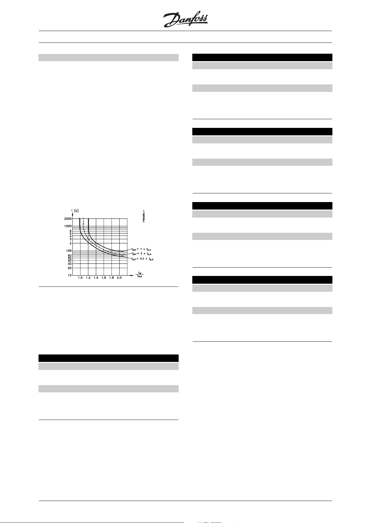
VLT® 5000 Crane
Description of choice:
Select No protection if no warning or tripping is
required when the motor is overloaded.
Select Thermistor warning if a warning is desired when
the connected thermistor - and thus the motor
overheats.
Select Thermistor trip if cutting out (trip) is desired when
the connected thermistor - and thus the motor
overheats.
Select ETR Warning 1,ifawarningistocome
up on the display when the motor is overloaded
according to the calculations.
Select ETR Trip 1 if tripping is desired when the motor
is overloaded according to the calculations.
The frequency converter can also be programmed
to give off a warning signal via one of the digital
outputs, in which case the signal is given both for
warning and for trip (thermal warning).
151 ROTOR RESISTANCE
Value:
Ohm
Function:
This parameter is for setting the value of the motor
rotor resistance for the Flux Vector control.
152 STATOR LEAKAGE REACTANCE
Value:
Ohm
Function:
Use this parameter for setting the value of the motor
stator leakage reactance for the Flux Vector control.
153 ROTOR LEAKAGE REACTANCE
Value:
Ohm
Function:
The value of the motor rotor leakage reactance for
the Flux Vector control is set in this parameter-
✭ Depends on unit
✭ Depends on unit
✭ Depends on unit
The motor data in parameters 150-158 must be set
correspondingly to the specific motor, in order for the
motor to run properly. As factory setting, the parameters
are set accordingly to the motor name plates.
If these parameters are not set correctly, it may
causeamalfunctionofthedrive.
150 STATOR RESISTANCE
Value:
Ohm
Function:
In this parameter the value of the motor stator
resistance for the Flux Vector control is set.
✭ Depends on unit
154 MAIN REACTANCE
Value:
Ohm
Function:
In this parameter the value of the motor main reactance
for the Flux Vector control is set-
✭ Depends on unit
✭ = factory setting. () = display text [] = value for use in communication via serial communication port
56
MG.50.N4.02 - VLT is a registered Danfoss trademark
Page 58

155 ROTOR INERTIA
Value:
2
kgm
✭ Depends on unit
Function:
Use this parameter for setting the value of the motor
rotor inertia for the Flux Vector control.
156 POLE NUMBER
Value:
✭4(4)
Function:
The number of poles on the motor for the Flux
Vector control is set in this parameter.
157 FIELD WEAKENING SPEED
Value:
0-6000 RPM
✭ Depends on unit
VLT® 5000 Crane
[4]
Function:
In this parameter the field weakening point for
the Flux Vector control is set.
158 IRONLOSS RESISTANCE
Value:
1 - 10000
✭ 10000
Function:
This parameter is for setting the ironloss resistance
valuefortheFluxVectorcontrol.
Motor equivalent diagram for an asynchronous motor:
✭ = factory setting. () = display text [] = value for use in communication via serial communication port
MG.50.N4.02 - VLT is a registered Danfoss trademark
Programming
57
Page 59

VLT® 5000 Crane
■References & Limits
202 OUT SPEED HI LIM
Value:
0-5000 RPM
✭ 3000 RPM
Function:
In this parameter, a maximum motor speed can be
selected corresponding to the highest frequency
at which the motor is to run.
See also parameter 205.
Description of choice:
A value from 0 - 5000 RPM can be selected.
205 MAX. REFERENCE
Value:
0.001 - 10.000
Function:
The Maximum reference gives the highest value that
can be assumed by the sum of all references.
207 RAMPUPTIME1
Value:
0.05 - 3600 sec.
✭ 0.85 sec.
✭ 3000
208 RAMPDOWNTIME1
Value:
0.05 - 3600 sec.
✭ 0.85 sec.
Function:
The ramp-down time is the deceleration time from the
rated motor frequency f
from the rated motor speed n
(parameter 104) to 0 Hz or
M,N
,providedthereis
M,N
no over-voltage in the inverter because of regenerative
operation of the motor, or if the generated current
reaches the torque limit (to be set in parameter 222).
211 JOG RAMP TIME
Value:
0.05 - 3600 sec.
✭ 0.85 sec.
Function:
The jog ramp time is the acceleration/deceleration time
from 0 Hz to the rated motor frequency f
(parameter
M,N
104). It is assumed that the output current is not higher
than the torque limit (set in parameter 221).
NB!:
Note that the jog function is only available
when running in FC profile!
Function:
The ramp-up time is the acceleration time from 0 Hz
to the rated motor frequency f
the rated motor speed n
M,N
(parameter 104) or
M,N
(if Speed control, closed
loop has been selected in parameter 100). This
presupposes that the output current does not reach
the torque limit (to be set in parameter 221).
The jog ramp time starts if a jog signal is given
via the control panel, the digital inputs or the
serial communication port.
Description of choice:
Set the desired ramp time.
212 Q STOP RAMP TIME
Value:
0.05 - 3600 sec.
✭ 0.85 sec.
Function:
The ramp-down time is the deceleration time
from the rated motor frequency to 0 Hz, provided
no over- voltage arises in the inverter because
of generating operation of the motor or if the
✭
= factory setting. () = display text [] = value for use in communication via serial communication port
58
MG.50.N4.02 - VLT is a registered Danfoss trademark
Page 60

generated current becomes higher than the torque
limit (set in parameter 222).
Quick-stop is activated by means of a signal on digital
input terminal 27, or via the serial communication port.
213 JOG FREQUENCY
Value:
0 - 4500 RPM
✭ 200 RPM
Function:
Jog frequency f
means a fixed output frequency
JOG
that the frequency converter supplies to the motor
when the Jog function is activated. Jog can be
activated via the digital inputs, serial communication
or via the LCP control panel, on the condition that
this is active in parameter 015 Local jogging.
NB!:
Note that this function only is availabel
when running in FC profile!
VLT® 5000 Crane
Description of choice:
In order to protect the motor from reaching pull-out
torque, the factory setting is 1.6 x the rated
motor torque (calculated value).
If a setting in parameters 101-106 is changed,
parameters 221/222 are not automatically
reversed to the factory setting.
Description of choice:
Set the required frequency.
221 TORQ LIMIT MOTOR
Value:
0.0 % - 170%
✭ 160 %
Function:
This is where to set the torque limit for motor operation.
The torque limiter is active in the frequency range
up to the rated motor frequency (parameter 104).
In the oversynchronous range, this function acts
as a current limiter, see figures below.
222 TORQ LIMIT GENER
Value:
0.0 % - 170%
✭ 160 %
Function:
This is where to set the torque limit for generating
operation. The torque limiter is active in the frequency
range up to the rated motor frequency (parameter 104
In the oversynchronous range, where the frequency is
higher than the rated motor frequency, this function
acts as a current limiter. See figures for parame
ter 221.
Description of choice:
If Resistor brake [1] has been selected in
parameter 400, the torque limit is changed to
1.6 x the rated motor torque.
234 MISSING MOTOR PHASE
Value:
* Enable (ENABLE)
Disable(DISABLE)
).
[0]
[1]
Function:
In this parameter it is possible to select monitoring
of the motor phases.
Description of choice:
If Enable is selected, the frequency converter
will react on a missing motor phase which will
result in alarm 30, 31 or 32.
= factory setting. () = display text [] = value for use in communication via serial communication port
✭
MG.50.N4.02 - VLT is a registered Danfoss trademark
Programming
59
Page 61

If Disable is selected, no alarm is given if a motor phase
is missing. The motor can be damaged/overheated if it
runs on only two phases. It is therefore recommended
to keep the missing motor phase function ENABLED.
235 PHASE LOSS MONITOR
Value:
Disable (DISABLE)
✭Enable (ENABLE)
Function:
In this parameter it is possible to select monitoring
of the input phases.
Description of choice:
If Enable is selected, the converter will react on a
missing input phase which results in alarm 4.
If Disable is selected, no alarm is given if a motor
phase is missing. The converter may be damaged
when running with a missing input phase. It is
therefore recommended to keep the phase loss
monitor function ENABLED.
VLT® 5000 Crane
[0]
[1]
236 Low speed reference current
(LOW SPEED CURRENT)
Value:
0 - 160%
Function:
The control mode at low speed in open loop
speed control is a rotation of a current vector with
fixed amplitude. With this parameter, the value
of this fixed current vector is set.
Description of choice:
The reference is set in percentage of the nominal
current of the motor.
✭ 50%
✭ = factory setting. () = display text [] = value for use in communication via serial communication port
60
MG.50.N4.02 - VLT is a registered Danfoss trademark
Page 62

VLT® 5000 Crane
■Inputs & Outputs
When running in Crane profile, the digital inputs are
hard coded. This means that there are no functions to
choose between, as the settings cannot be changed.
The table below shows the inputs in question.
Digital inputs Terminal no. 16 17 18 19 27 29 32 33
parameter 300 301 302 303 304 305 306 307
Value:
Crane ready (CRANE READY) [30]
Positioning (POSITIONING) [30]
Start lowering (START LOWERING) [30]
Start hoisting (START HOISTING) [30]
Quick stop (QUICK STOP) [30]
Gear choice (GEAR CHOICE) [30]
Load contact 1 (LOAD CONTACT 1) [30]
Load contact 2 (LOAD CONTACT 2) [30]
The functions are described further below:
Crane ready input signal for system ready.
Positioning is selected if the frequency converter
is to work in positioning mode. Positioning mode
is only available when running in remote control.
If the signal is removed, the frequency converter
is to operate in normal mode.
Start lowering is selected when the frequency
converter is to lower a load. This function is
only available in remote control.
Start hoisting this function enables hoisting of a load
when the frequency converter is in remote control.
Quick stop ramps the motor speed down to zero
with the selected quick ramp time.
Gear choice is used whenever the gear is changed
in order to perform a load estimation. The function
is only available in remote control.
Load contact 1 is the high load contact, which is used
for load monitoring when operating in remote control.
Load contact 2 is the low load contact,
which is also used for load monitoring when
operating in remote control.
= factory setting. () = display text [] = value for use in communication via serial communication port
✭
MG.50.N4.02 - VLT is a registered Danfoss trademark
Programming
61
Page 63

VLT® 5000 Crane
The table below is only relevant when running
in FC profile:
Digital inputs Terminal no. 16 17 18 19 27 29 32 33
parameter 300 301 302 303 304 305 306 307
Value:
No function (NO OPERATION) [0] [0] ✭ [0] [0] [0] [0]✭ [0]✭
Reset (RESET) [1]✭ [1] [1] [1] [1]
Coasting stop, inverse (COAST INVERSE) [0]✭
Quick-stop, inverse (QSTOP INVERSE) [2]
Stop inverse (STOP INVERSE) [2] [2] [4] [2] [2] [2]
Start (START) [1]✭
Reversing (REVERSING) [1]✭
Jog (JOGGING) [4] [4] [5]✭ [4] [4]
Function:
The different possible functions related to the inputs
on terminals 16-33 listed in the table above, are only
accessable when running in FC profile..
The maximum frequency for terminal 16, 17, 18,
19, 27, 32, 33 and 37 is 5 kHz. The maximum
frequency for terminal 29 is 50 kHz.
Description of choice:
No function is selected if the frequency converter is
not to react to signals transmitted to the terminal.
Reset zeroes the frequency converter after an alarm;
however, not all alarms can be reset.
Coasting stop inverse is used for making the
frequency converter let go of the motor to make it coast
freely to stop. Logic ’0’ leads to coasting stop and reset.
Quick-stop inverse is used for stopping the motor in
accordance with the quick-stop ramp (set in parameter
212). Logic ’0’ leads to a quick-stop.
Stop inverse is activated by interrupting the
voltage to the terminal. This means that if the
terminal has no voltage, the motor cannot run.
The stop will be effected in accordance with the
selected ramp (parameters 207/208).
None of the above-mentioned stop
commands (start-disable) are to be used
as disconnection switch in connection
with repairs. Cut mains instead.
Start, is selected if a start/stop (operating
command, group 2) command is desired. Logic
’1’ = start, logic ’0’ =stop.
Reversing is used for changing the direction of rotation
of the motor shaft. Logic ’1’ will lead to reversing.
The reversing signal only changes the direction of
rotation; it does not activate the start function.
Jog is used for overriding the output frequency to
the jog frequency set in parameter 213. The ramp
time can be set in parameter 211. Jog is not active
if a stop command has been given (start-disable).
Jog does not override a start signal.
NB!:
The Jog function is not available in Crane profile.
If the VLT 5000 Crane is programmed to run
as a normal VLT 5000 (see parameter 512),
the Jog function will, however, be available.
Analogue inputs terminal no. 53(voltage) 58(current) 60(current)
parameter 308 352 314
Value:
No operation (NO OPERATION) [0] [0] [0]
Reference (REFERENCE) [1] ✭ [1]✭ [1] ✭
Thermistor (THERMISTOR INPUT) [4]
✭ = factory setting. () = display text [] = value for use in communication via serial communication port
62
MG.50.N4.02 - VLT is a registered Danfoss trademark
Page 64

VLT® 5000 Crane
Function:
This parameter allows a choice of the desired
option on terminal 53.
Scaling of the input signal is effected in
parameters 309 and 310.
Description of choice:
No operation. Is selected if the frequency converter is
not to react to signals connected to the terminal.
Reference. Is selected to enable change of reference
by means of an analogue reference signal.
If other inputs are connected, these are added
up, taking account of their signs.
Thermistor. Is selected if a thermistor integrated
in the motor is to be able to stop the frequency
converter in case of motor overtemperature. The
cut-out value is > 3 kohm.
used (parameter 317 Time out and 318 Function after
time out), the value set must be higher than 1 Volt.
310 AI 53 SCALE HIGH
Value:
0 - 10.0 Volt
✭ 10.0 Volt
Function:
This parameter is used for setting the signal value that
is to correspond to the maximum reference value,
parameter 205 Maximum reference, Ref
MAX
.
Description of choice:
Set the required voltage value. For reasons of
accuracy, compensation should be made for
voltage losses in long signal cables.
314 AI [mA] 60 FUNCT
Value:
✭No function (NO OPERATION)
Reference (REFERENCE)
[0]
[1]
If a motor features a KLIXON thermal switch instead,
this can also be connected to the input. If motors
run in parallel, the thermistors/thermal switches
can be connected in series (total resistance <
3 kohm). A thermistor or a Klixon switch must
be set between terminal 50 and terminal 53.
Parameter 128 must be programmed for Thermistor
warning [1] or Thermistor trip [2].
309 AI 53 SCALE LOW
Value:
0.0 - 10.0 Volt
✭ 0.0 Volt
Function:
This parameter is used for setting the signal value that
is to correspond to the minimum reference (0 RPM).
Function:
This parameter allows a choice between the
different functions available for the input, terminal 60.
Scaling of the input signal is effected in parameter
315 Terminal 60, min. scaling and parameter
316 Terminal 60, max. scaling.
Description of choice:
No function [0]. Is selected if the frequency converter
is not to react to signals connected to the terminal.
Reference [1]. If this function is selected, the reference
can be changed by means of an analogue reference
signal. If reference signals are connected to more than
one input, these reference signals must be added up.
315 AI 60 SCALE LOW
Value:
0.0 - 20.0 mA
✭ 4.0 mA
Function:
This parameter is for setting the signal value
corresponding to the minimum reference (0 RPM).
Description of choice:
Set the required voltage value. For reasons of accuracy,
compensation should be made for voltage losses in
long signal cables. If the Time out function is to be
Description of choice:
Set the required current value. If the Time out function is
to be used (parameter 317 Time out and 318 Function
after time out) the value set must be higher than 2 mA.
✭ = factory setting. () = display text [] = value for use in communication via serial communication port
MG.50.N4.02 - VLT is a registered Danfoss trademark
Programming
63
Page 65

VLT® 5000 Crane
316 AI 60 SCALE HIGH
Value:
0.0 - 20.0 mA
✭ 20.0 mA
Function:
This parameter is used for setting the signal value that
is to correspond to the maximum reference value,
parameter 205 Maximum reference value, Ref
MAX
.
317 LIVE ZERO TIME O
Value:
1 - 99 sec.
✭ 10 sec.
Function:
If the signal value of the reference signal connected
to one of the input terminals 53 or 60 falls below 50
% of the minimum scaling for a period longer than
the time set, the function selected in parameter 318
Function after time out will be activated. This function
is only active if in parameter 309 Terminal 53, min.
scaling a value higher than 1 Volt has been selected,
or if in parameter 315/353 Terminal 58, min. scaling
a value higher than 2 mA has been selected.
Description of choice:
Set the required time.
318 LIVE ZERO FUNCT.
Value:
✭No operation (NO OPERATION)
Freeze output frequency (FREEZE OUTPUT FREQ.)
Stop (STOP)
Jog (JOG)
Max. speed (MAX SPEED)
Stop and trip (STOP AND TRIP)
Function:
This parameter allows a choice of the function
to be activated after the expiration of the Time
out (parameter 317 Time out).
Description of choice:
The output frequency of the drive can be:
- frozen at the present frequency [1]
- overruled to stop [2]
- overruled to jog frequency [3]
- overruled to max. output frequency [4]
- overruled to stop with subsequent trip [5]
[0]
[1]
[2]
[3]
[4]
[5]
319 AO 42 FUNCTION
Value:
✭No operation (NO OPERATION)
0 - 100 Hz = 0-20mA
(0 - 100 HZ = 0-20MA)
0-100Hz=4-20mA
(0 - 100 HZ = 4-20 MA)
Ref min-max = 0-20 mA
(REF MIN-MAX = 0-20 MA)
Ref min.-max. 4-20 mA
(REF MIN-MAX = 4-20 MA)
FB min-max 0-20 mA
(FB MIN-MAX = 0-20 MA)
FB min-max 4-20 mA
(FB MIN-MAX = 4-20 MA)
0-I
(0- I
0-I
(0-I
0-T
(0-T
0-T
(0-T
0-T
(0 - T
0-T
(0 - T
0-P
(0 - P
0-P
(0 - P
=0-20mA
max
MAX
4-20 mA
max
=4-20MA)
MAX
0-20 mA
lim
=0-20MA)
LIM
4-20 mA
lim
=4-20MA)
LIM
nom
NOM
nom
NOM
nom
NOM
nom
NOM
=0-20MA)
=0-20mA
=0-20MA)
=4-20mA
=4-20MA)
= 0-20mA
= 0-20MA)
= 4-20mA
= 4-20MA)
0 - Speedmax = 0-20mA
(0 - SPEEDMAX = 0-20MA)
0 - Speedmax = 4-20mA
(0 - SPEEDMAX = 4-20MA)
± 160% torque = 0-20mA
(± 160% TORQUE = 0-20MA)
± 160% torque = 4-20mA
(± 160% TORQUE = 4-20MA)
Function:
The analogue output can be used for stating a
process value. It is possible to choose two types of
output signals 0 - 20 mA or 4 - 20 mA.
If used as a voltage output (0 - 10 V), a pull-down
resistor of 500
must be fitted to common
(terminal 39). If the output is used as a current
output the resulting resistance from the equipment
connected may not exceed 500
.
Description of choice:
No operation. Is selected if the analogue
output is not to be used.
[40]
[41]
[42]
[43]
[44]
[45]
[46]
[47]
[48]
[49]
[50]
[51]
[52]
[53]
[54]
[55]
[56]
[57]
[58]
= factory setting. () = display text [] = value for use in communication via serial communication port
✭
64
MG.50.N4.02 - VLT is a registered Danfoss trademark
Page 66

VLT® 5000 Crane
0 - 100 Hz = 0-20 mA/4-20 mA.
An output signal proportional to the output frequency
in the range 0 - 100 Hz is obtained.
Ref min-max = 0-20 mA/4-20 mA.
An output signal is obtained which is proportional
to the set reference in the range from 0 - Ref
MAX
is obtained (parameter 205).
FB
MIN
-FB
= 0-20 mA/ 4-20 mA.
MAX
An output signal is obtained, which is proportional to the
feedback in the range from 0 - Ref
0-I
= 0-20 mA/4-20 mA.
MAX
(parameter 205).
MAX
An output signal is obtained, which is proportional
to the output current in the interval 0 - I
0-T
= 0-20 mA/4-20 mA.
lim
MAX
.
An output signal is obtained which is proportional to
the output torque in the range 0 - T
0-T
= 0-20 mA/4-20 mA.
nom
(parameter 221).
LIM
An output signal is obtained, which is proportional
to the output torque in the range 0 - T
NOM
(the rated motor torque).
323 RELAY 1-3 FUNCT.
Value:
✭Mechanical brake control
(MECHANICAL BRAKE CONTROL)
Function:
This output activates a relay switch.
Relay switch 01 can be used for bringing status and
warnings and enables monitoring of the mechanical
brake. The relay is activated when the conditions for
the relevant data values have been fulfilled.
Activation/deactivation can be delayed in
parameter 324/325.
NB!:
This parameter cannot be changed!
Description of choice:
See description of parameter 341.
Connections - see the below drawing.
[14]
0-P
= 0-20 mA/4-20 mA.
nom
An output signal proportional to the rated
motor output is obtained.
0 - Speedmax = 0-20 mA/4-20 mA.
An output signal is obtained which is proportional to
the output speed in the range 0 - Speedmax
(parameter 202).
± 160% torque = 0-20 mA/4-20 mA.
An output signal is obtained which is proportional to
±160% of the rated motor torque. -160% yields 0/4
mA, 0% yields 10/12 mA and 160% yileds 20 mA.
321 AO 45 FUNCT.
Value:
Function:
On these analogue outputs (data value [40]-[58])
thereisachoiceof0-20mAor4-20mA.
Description of choice:
See description of parameter 319
324 RELAY 1-3 ON DL
Value:
0.00 - 10.00 min.
✭ 0.00 sec.
Function:
This parameter makes it possible to delay the cut-in
time of relay 01 (terminals 01-02).
325 RELAY 1-3 OFF DL
Value:
0.00 - 10.00 min.
✭ 0.00 sec.
Function:
This parameter makes it possible to delay the cut-out
time of relay 01 (terminals 01-03).
✭ = factory setting. () = display text [] = value for use in communication via serial communication port
MG.50.N4.02 - VLT is a registered Danfoss trademark
Programming
65
Page 67

VLT® 5000 Crane
326 RELAY 4-5 FUNCT.
Value:
See parameter 341
Function:
This output activates a relay switch.
Relay switch 04 can be used for bringing status and
warnings. The relay is activated when the conditions
for the relevant data values have been fulfilled.
Description of choice:
See description of parameter 341.
Connections - see the below drawing.
329 ENCODER PULSES
Value:
✭1024 pulses /rev. (1024)
[1024]
(BRAKING, NO BR. WARN.)
Brake fault (IGBT SHORT-CIRCUIT FAULT)
Mechanical brake control
(MECH. BRAKE CONTROL)
Mechanical brake ready no fault
(MECH. BRAKE RDY/NO F)
Thermal warning (THERMAL WARNING)
Unit ready and no thermal warning
(READY/NO THERM WARN)
Unit ready and no over/undervoltage
(RDY NO OVER/UNDERVOL)
Control word bit 11 (CTRL WORD BIT 11)
Control word bit 12 (CTRL WORD BIT 12)
Function:
Selects the function for output on the digital terminal
46. If the condition of the selected function is true, the
output level is 24 V (active), otherwise it is 0 V (inactive).
Description of choice:
No operation
Selected if the output should not react to any
signals. The output is 0 V.
[12]
[13]
[14]
[15]
[16]
[17]
[18]
[19]
[20]
Function:
This is where to set the encoder pulses per revolution.
This parameter is only available in Speed control,
closed loop (parameter 100).
Description of choice:
Read the correct value from the encoder.
Signal level 0 - 5V (RS 422)
Signals necessary: A, Inv. A, B, Inv. B, Z and Inv. Z.
341 SIGNAL OUTPUT 46
Value:
✭No operation (NO OPERATION)
Control ready (CONTROL READY)
Unit ready (UNIT READY)
Enabled (ENABLED)
VLT running (VLT RUNNING)
VLT running and no warning
(RUNNING/NO WARNING)
VLT running on reference and no warning
(RUN ON REF/NO WARN)
Positioning (POSITIONING)
Normal run (NORMAL RUN)
Alarm (ALARM)
Alarm or warning (ALARM OR WARNING)
Torque limit motor mode
(TORQUE LIMIT MOTOR M)
Braking, no brake warning
[10]
[11]
[0]
[1]
[2]
[3]
[4]
[5]
[6]
[7]
[8]
[9]
Control ready
The frequency converter is ready for use; the
control card receives supply voltage.
Unit ready
The frequency converter control card is receiving
a supply signal and the frequency converter
is ready for operation.
Enabled
The frequency converter is ready for use; no start or stop
command has been given (start/disable). No warning.
Running
This signal is active when a start command has
been given or a stop command has been given
and the drive has not stopped.
Running and no warning
This signal is active when a start command has been
given or a stop command has been given and the
drive has not stopped. No warning.
Running on reference and no warning
Speed according to reference. No warning.
Positioning
The output is active during positioning.
Normal run
The output is active during normal run, ie.
not during positioning.
✭
= factory setting. () = display text [] = value for use in communication via serial communication port
66
MG.50.N4.02 - VLT is a registered Danfoss trademark
Page 68

VLT® 5000 Crane
Alarm
The output is activated by alarm.
Alarm or warning
The output is activated by alarm or warning.
Torq ue l im it
The torque limit in parameter 221 has been exceeded.
Braking, no brake warning
Thebrakeisactiveandtherearenowarnings.
Brake fault
The output is a logical "1" when the brake IGBT has
short-circuited. This function is used to protect the
frequency converter if there is a fault on the brake
modules. To avoid a potential fire in the brake resistor,
the output/relay can be used to cut out the supply
voltage from the frequency converter.
Mechanical brake control
Enables control of an external mechanical brake.
Mechanical brake ready, no fault
The external mechanical brake is ready and
has no fault detected.
Function:
For information see table in parameter 308
Description of choice:
See parameter 314 for information
353 ANALOGUE IN 58 SCALE LOW
Value:
0-20 mA
✭ 4mA
Function:
This parameter is for setting the signal value
corresponding to the minimum reference (0 RPM).
Description of choice:
Set the required value. If the Timeout function is
to be used (parameters 317 and 318) the value
set must be higher than 2mA.
354 ANALOGUE IN 58 SCALE HIGH
Value:
0-20 mA
✭ 20 mA
Thermal warning
The temperature limit has been exceeded in
either the motor, the frequency converter, the
brake resistor or the thermistor.
Unit ready and no thermal warning
The frequency converter is ready for use, the control
card receives supply voltage and there are no control
signals on the inputs. No over-temperature.
Unit ready and no over/undervoltage
The frequency converter is ready for use, the control
card receives supply voltage and there are no
control signals on the inputs. The mains voltage
is within the permitted voltage range.
Control word bit 11
The output is controlled by bit 11 in serial control
word. See Serial communication in Appendix.
Control word bit 12
The output is controlled by bit 12 in serial control
word. See Serial communication in Appendix.
Function:
This parameter is used for setting the signal value that
is to correspond to the maximum reference value,
parameter 205 Maximum reference value, Ref
MAX
.
355 SIGNAL OUTPUT 26
Value:
See parameter 341 for choices
Function:
Selects the function for output on the digital
output terminal 26. If the condition of the selected
function is true, the output level is 24 V (active),
otherwise it is 0 V (inactive)
Description of choice:
See parameter 341 for choices
352 AI [mA] 58 FUNCT.
Value:
No operation (NO OPERATION)
✭Reference (REFERENCE)
[0]
[1]
✭ = factory setting. () = display text [] = value for use in communication via serial communication port
MG.50.N4.02 - VLT is a registered Danfoss trademark
Programming
67
Page 69

VLT® 5000 Crane
■Application Functions
400 BRAKE FUNCTION
Value:
Off (OFF)
✭Resistor brake (RESISTOR)
Function:
The factory setting is On [1] for VLT
5052-5062 400-500 V.
Resistor brake [1] is used for programming the
frequency converter for connection of a brake
resistor. The connection of a brake resistor
allows a higher intermediate circuit voltage during
braking (generating operation).
The Resistor brake [1] function is only active in units
with an integral dynamic brake (SB and EB units).
Description of choice:
Select Resistor brake [1] if a brake resistor
is part of the system.
401 BRAKE RES. (OHM)
Value:
Depends on the unit
Function:
This parameter gives the ohmic value of the brake
resistor. This value is used for monitoring the
power to the brake resistor provided this function
has been selected in parameter 403.
✭ Depends on the unit
[0]
[1]
403 POWER MONITORING
Value:
Off (OFF)
✭Warning (WARNING)
Trip (TR I P)
Function:
This parameter allows monitoring of the power
transmitted to the brake resistor. The power is
calculated on the basis of the resistor ohm value
(parameter 401), the intermediate circuit voltage and
the resistor running time. If the power transmitted
over 120 sec. exceeds 100% of the monitoring limit
(parameter 402) and Warning [1] has been selected,
a warning will come up on the display. The warning
will disappear if the power goes below 80%. If the
calculated power exceeds 100% of the monitoring limit
and Trip [2] has been selected in parameter 403 Power
monitoring , the VLT frequency converter will cut out
while giving an alarm. If power monitoring has been
selected as Off [0] or Warning [1], the brake function
will remain active, even if the monitoring limit has been
exceeded. This may lead to thermal overload of the
resistor. It is also possible to have a warning via the
relay/digital outputs. The typical measuring accuracy
of the power monitoring depends on the accuracy of
the resistor ohmic value (better than ± 20%).
Description of choice:
Select whether this function is to be active (
Warning/Alarm) or inactive (Off).
[0]
[1]
[2]
404 BRAKE TEST
402 BR.POWER LIM.KW
Value:
Depends on the unit
Function:
This parameter gives the monitoring limit of the
power transmitted to the brake resistor.
Description of choice:
The monitoring limit is determined as a product of
the maximum duty cycle (120 sec.) that will occur
and the maximum power of the brake resistor at that
duty cycle according to the following formula.
For 400 - 500 V units: P =
✭
= factory setting. () = display text [] = value for use in communication via serial communication port
✭ Depends on the unit
Value:
✭Off (OFF)
Warning (WARNING)
Trip (TR I P)
Function:
In this parameter a testing and monitoring function
can be integrated which will give a warning or an
alarm. On power-up it will be tested whether the brake
resistor is disconnected. The test of whether the brake
resistor is disconnected is carried out during braking,
while the test of whether the IGBT is disconnected
is carried out when there is no braking. A warning
or trip disconnects the brake function.
The testing sequence is as follows:
1. If the intermediate circuit voltage is higher than the
brake starting voltage, discontinue the brake check.
2. If the intermediate circuit voltage is unstable,
discontinue the brake check.
3. Carry out a brake test.
[0]
[1]
[2]
68
MG.50.N4.02 - VLT is a registered Danfoss trademark
Page 70

VLT® 5000 Crane
4. If the intermediate circuit voltage is lower than the
starting voltage, discontinue the brake check.
5. If the intermediate circuit voltage is unstable,
discontinue the brake check.
6. If the braking power is higher than 100%,
discontinue the brake check.
7. If the intermediate circuit voltage is higher than
the intermediate circuit voltage -2% before the
brake test, discontinue the brake check and
give off a warning or alarm.
8. Brake check OK.
Description of choice:
If Off [0] is selected, this function will still monitor whether
the brake resistor and the brake IGBT short-circuit
during operation, in which case it will give off a warning.
If Warning [1] is selected, the brake resistor and brake
IGBT will be monitored with respect to short-circuiting.
In addition, on power-up it will be checked whether
the brake resistor has been disconnected.
NB!:
A warning in connection with Off [0] or Warning
[1] can only be removed by disconnecting the
mains supply and turning it back on, provided
the fault has been corrected. Please note that in
connection with Off [0] or Warning [1] the frequency
converter will continue even if a fault has been found.
421 SPEED FILT. TIME
Value:
1-20ms
Function:
Oscillations on the feedback signal are dampened
by a lowpass filter and the resolution on speed
measurement is increased. This is necessary for the
Flux Vector control to function properly. The Speed
Filter Time is used with Speed Control, Closed Loop.
✭ 3.2 ms
In the case of Tr ip [2], the frequency converter will
cut out while giving an alarm (trip locked) if the brake
resistor has short-circuited or been disconnected
or if the brake IGBT has short-circuited.
405 RESET MODE
Value:
✭Manual reset (MANUAL RESET)
Reset at power-up (RESET POWER UP)
Function:
This parameter makes it possible to select the
reset function desired after tripping.
After reset, the frequency converter can be restarted.
Description of choice:
If Manual reset [0] is selected, reset must be
effected via the [RESET] key.
Warning: The motor may start
without warning.
[0]
[11]
Description of choice:
Ifatimeconstant(τ) eg. of 10 ms is programmed, the
cut-off frequency for the lowpass filter will be 1/0.01 =
100 RAD/sec., corresponding to (100/2 x π) = 16.0
Hz. This means that the PI regulator will o
a feedback signal that varies by a frequency of less
than 16.0 Hz. If the feedback signal varies by a higher
frequency than 16.0 Hz, the PI regulator will not react.
For parameter group 5xx, please refer to the following
chapter, Serial Communication.
nly regulate
Programming
= factory setting. () = display text [] = value for use in communication via serial communication port
✭
MG.50.N4.02 - VLT is a registered Danfoss trademark
69
Page 71

VLT® 5000 Crane
■Service Functions
600-605 Operating Data
Value:
Par. no. Description Display text Unit Range
600 Operating hours (OPERATING HOURS) Hours 0-130,000.0
601 Hours run (RUNNING HOURS) Hours 0-130,000.0
602 kWh counter (KWH COUNTER) kWh Depends on unit
603 Number of power-ups (POWER UPS) Number of times 0-9999
604 Number of
overtemperatures
605 Number of overvoltages (OVER VOLTS) Number of times 0-9999
(OVER TEMPS) Number of times 0-9999
Function:
These parameters can be read out via the serial
communication port and the LCP control unit.
Description of choice:
Parameter 600, Operating hours:
Gives the number of hours the frequency converter has
been operating. The value is saved every hour and
when there is a mains failure. This value cannot be reset.
Parameter 601, Hours run:
Gives the number of hours the motor has been
operating since the reset in parameter 619 Reset
of hours-run counter. The value is saved every
hour and when there is a mains failure.
Parameter 602, kWh counter:
Gives the frequency converter’s output energy in
kWh. The calculation is based on the mean kW
value over one hour. This value can be reset using
parameter 618 Reset of kWh counter.
Range: 0 - depends on unit.
Parameter 603, Number of power-ups:
Gives the number of power-ups of the supply voltage
undertaken on the frequency converter.
Parameter 604, Number of overtemperatures:
Gives the number of overtemperature faults that have
been registered on the frequency converter’s heat sink.
Parameter 605, Number of overvoltages:
Gives the number of overvoltages of the intermediate
circuit voltage in the frequency converter. This is only
counted when Alarm 7 Overvoltage is active.
615 F. LOG: ERROR CODE
Value:
Table with error codes, see Warnings and Alarms
Function:
This parameter makes it possible to see the
reason why a trip occurs.
10 (0-9) log values are stored.
The lowest log number (0) contains the latest/most
recently saved data value; the highest log number
(9) contains the oldest data value.
Description of choice:
Given as a number code, in which the trip
number refers to an alarm code.
Reset the fault log after manual initialisation.
616 F.LOG: TIME
Function:
This parameter makes it possible to see the total
number of operating hours before the trip occurred.
10 (0-9) log values are stored.
The lowest log number (0) contains the latest/most
recently saved data value, while the highest log
number (9) contains the oldest data value.
Description of choice:
Indication range: 0.0 - 9999.9.
Reset the fault log after manual initialisation.
617 F.LOG:VALUE
Value:
[Index 0.0 - 999.9]
Function:
This parameter makes it possible to see at what
current or voltage a given trip occurred.
✭
= factory setting. () = display text [] = value for use in communication via serial communication port
70
MG.50.N4.02 - VLT is a registered Danfoss trademark
Page 72

VLT® 5000 Crane
Description of choice:
Read out as one value.
Indication range: 0.0 - 999.9.
Reset the fault log after manual initialisation.
618 RESET kWh COUNT
Value:
✭No reset (DO NOT RESET)
Reset (RESET COUNTER)
Function:
Resetting parameter 602 kWh counter to zero.
Description of choice:
If Reset [1] is selected and you press the [OK] key, the
frequency converter’s kWh counter is reset to zero. This
parameter cannot be selected via serial communication.
NB!:
When the [OK] key is activated, the
counter is reset to zero.
619 RESET RUN. HOUR
Value:
✭No reset (DO NOT RESET)
Reset (RESET COUNTER)
Function:
Resetting of parameter 601 Hours run to zero.
Description of choice:
If Reset [1] is selected and you press the [OK]
key, the frequency converter’s parameter 601 is
reset to zero Hours run. This parameter cannot
be selected via serial communication.
NB!:
When the [OK] key is activated the
parameter is reset to zero.
[0]
[1]
[0]
[1]
This function will not become active until the mains
supply to the frequency converter has been turned
off and then turned on again.
Description of choice:
Normal function [0] is selected for normal operation
with the motor in the selected application.
Control card test [2] is selected if control of
the analogue and digital inputs, as well as the
analogue, digital relay outputs and the +10 V control
voltage is desired. A test connector with internal
connections is required for this test.
Use the following procedure for the control card test:
1. Select Control card test.
2. Cut off the mains supply and wait for the
lightinthedisplaytogoout.
3. Insert the test plug (see below).
4. Connect to mains.
5. The frequency converter expects the [OK] key to be
pressed (if no LCP, set to Normal operation,when
the frequency converter will start up as usual).
6. Carry out various tests.
7. Press the [OK] key.
8. Parameter 620 is automatically set to
Normal operation.
If a test fails, the frequency converter will move into
an infinite loop. Replace control card.
Test plugs (connect the following terminals
to each other):
4-16
5-12
17 - 18 - 19 - 26
20 - 39 - 55
27 - 29 - 32 - 33 - 37 - 46
42 - 60
45 - 53 - 58
620 OPERATION MODE
Value:
✭Normal function (NORMAL OPERATION)
Control card test (CONTROL CARD TEST)
Initialisation (INITIALIZE)
Function:
In addition to its normal function, this parameter
can be used for two different tests.
Also, all parameters (except parameters
603-605) can be initialised.
✭ = factory setting. () = display text [] = value for use in communication via serial communication port
MG.50.N4.02 - VLT is a registered Danfoss trademark
[0]
[2]
[3]
Programming
71
Page 73
VLT® 5000 Crane
Initialisation [3] is selected if the factory setting of
the unit is desired without resetting parameters
500, 501 + 600 - 605 + 615 - 617.
NB!:
The motor must be stopped before initialisation
can be carried out.
Procedure for initializing:
1. Select Initialisation.
2. Press the [OK] key.
3. Cut off the mains supply and wait for the
light in the display to go out.
4. Connect to mains.
Manual initialisation can be carried out by holding down
three keys at the same time as the mains voltage is
connected. Manual initialisation sets all parameters to
the factory setting, except 600-605. The procedure
for manual initialisation is as follows:
1. Disconnect the mains voltage and wait for the
light in the display to disappear.
2. Hold down [DISPLAY/STATUS]+[MENU]+[OK] while
at the same time connecting the mains supply. The
display will now read MANUAL INITIALIZE.
3. When the display reads UNIT READY, the frequency
converter has been initialized.
621-631 Type plate
Value:
Par.
no
Description
Nameplate
Display text
621 Unit type (DRIVE TYPE)
622 Power section (POWER SECTION)
62 3 V LT ord er in g n um be r (VLT OR DER I NG NO )
624 Software version (SOFTWARE VERSION)
625 LCP identification no. (LCP VERSION)
626 Database identification no. (DATABASE VER.)
627 Power parts version (POWER UNIT DB ID)
628 Application option type (APP. OPTION)
629 Application ordering (APP. ORDERING)
630 Communication option type (COM. OPTION)
631 Communication ordering (COM: ORDERING)
Function:
The unit’s main data can be read out from parameters
621 to 635 Type plate using the LCP control unit or
serial communication. Parameters 640 - 642 can
also be seen on the unit’s integral display.
Description of choice:
Parameter 621 Type plate: Unit type:
Givesunitsizeandmainsvoltage.
Example: VLT 5250 400-500V.
Parameter 622 Type plate: Power section:
The power section states the given powe
section being used.
Parameter 623 Type plate: VLT ordering number:
Ordering number states the ordering number of the
VLT type in question. For example: 175Z3120.
Parameter 624 Type plate: Software v
The unit’s present software version number
appears here.
Example: V 20.00
r
ersion no.
Parameter 625 Type plate: LCP ID number:
The ID number of the unit’s LCP appears here.
Example: ID 1.42 2 kB
Parameter 626 Type plate: Database ID number:
The ID number of the software’s database appears here.
Example: ID 1.14.
Parameter 627 Type plate: Power section version:
The ID number of the unit’s power section appears here.
Example: ID 1.15.
Parameter 628 Type plate: Application option type:
Here you can see which types of application options
are installed in the frequency converter.
Parameter 630 Type plate: Communication option type:
Here you can see which types of communication
options are installed in the frequency converter.
✭ = factory setting. () = display text [] = value for use in communication via serial communication port
72
MG.50.N4.02 - VLT is a registered Danfoss trademark
Page 74

639 FLASH TEST
Value:
Off (OFF)
✭On (ON)
Function:
Checks the consistency of the program in flash
proms during every power-up.
650 PASSWORD
Value:
✭Password level 2 (PASSWORD LEVEL 2)
Password level 1 (PASSWORD LEVEL 1)
Function:
After entering the correct password the new protection
levelisshownintheLCP.Afterpowerupthe
password is to be re-entered in order to enable
changing the protected parameters.
[000002]
[110775]
VLT® 5000 Crane
[0]
[1]
✭ = factory setting. () = display text [] = value for use in communication via serial communication port
MG.50.N4.02 - VLT is a registered Danfoss trademark
Programming
73
Page 75

VLT® 5000 Crane
■Crane Functions
■Introduction to Crane Parameters
This parameter group contains all the crane specific
parameters making the VLT 5000 Crane stand
out from other VLT products.
It is important to notice that these
parameters only should be handled by
skilled personnel as wrong handling
may cause serious accidents!
701 LOAD LOW
Value:
0 - 5000 RPM
Function:
The values for Load Low are set in this parameter
in RPM. If the speed set for the load contact is
exceeded, the frequency converter will trip.
Description of choice:
The value of parameter 701 may only be higher or
equal to the value of parameter 702.
✭ Depends on unit
704 LOW SPD. AT ERROR
Value:
-200 - 200 RPM
Function:
With this parameter you can choose the lowering
speed at brake fault 1, which is when the system
brake cannot hold the load.
705 BRAKE ON RPM
Value:
5-50RPM
Function:
This parameter allows choosing the min. speed at
which the system brake signal of relay 1-3 must be
removed (the system brake takes over the load).
707 HOIST DIRECTION
Value:
✭0(FORWARD)
1 (BACKWARD)
✭ 50 RPM
✭ 20 RPM
[0]
[1]
702 LOAD HIGH
Value:
0 - 1250 RPM
Function:
The values for Load High are set in this
parameter in RPM.
If the speed set for the load contact is exceeded,
the frequency converter will trip.
703 LOAD MONITORING
Value:
Disable (DISABLE)
✭Enable (ENABLE)
Function:
Load Monitoring of load contacts 1 and 2 can be
either disabled or enabled in this parameter.
✭ Depends on unit
[0]
[1]
Function:
In this parameter the direction, in which the motor
is to rotate during hoisting, is set.
708 START TORQUE
Value:
0 - 170%
Function:
This parameter allows choosing the start torque
forthemotorwhentakingovertheloadfromthe
system brake. Set the start torque in % of the
rated motor torque set in the software.
709 RAMP TORQUE
Value:
0.0 - 2 SEC
Function:
With this parameter the build-up time of the
start torque is set.
✭ 100%
✭ 0.2 SEC
✭ = factory setting. () = display text [] = value for use in communication via serial communication port
74
MG.50.N4.02 - VLT is a registered Danfoss trademark
Page 76

712 BRAKE MONITOR
Value:
0 (DISABLE)
✭1(ENABLE)
Function:
This parameter allows disabling the system brake. The
parameter is used for testing the unit. For reasons of
safety the parameter has been factory set for "ON".
713 DERATE LOWERING
Value:
0.6 - 1N/A
✭ 0.8 N/A
Function:
With this parameter the output during lowering is
reduced. 1.00 equals rated power output.
[0]
[1]
VLT® 5000 Crane
718 ENCODER MONITOR
Value:
0 (DISABLE)
✭1(ENABLE)
Function:
This parameter makes it possible to choose between
disable and enable in order not to monitor or to
monitor the encoder hardware.
720 DRUM INERTIA 1
Value:
0 - 1kgm
Function:
This parameter is used in the load estimator to
calculate the static load on the motor by setting
the inertia of the cable drum in gear 1.
2
✭ Depends on unit
[0]
[1]
714 DERATE HOISTING
Value:
0.6-1N/A
✭ 1N/A
Function:
This parameter is for decreasing the output power
determined by the load estimator.
715 MECHANICAL BRAKE ON DELAY
Value:
0,1 - 20 sec.
✭ 0,5 sec.
Function:
The value indicates the required time before the
mechanical brake cuts in (relay 1-3). After the delay
time the system brake takes over the load.
716 MECHANICAL BRAKE OFF DELAY
Value:
0,1 - 20 sec.
✭ 0,5 sec.
Function:
The value indicates the required time before the
mechanical brake is released. After the delay time,
the system brake releases the load.
721 GEAR RATIO 1
Value:
0 - 200
✭ Depends on unit
Function:
This parameter is used in the load estimator to
calculate the static load on the motor by setting
the ratio of the gear in gear 1.
722 GEAR INERTIA 1
Value:
0-1kgm
2
✭ Depends on unit
Function:
This parameter is used in the load estimator to
calculate the static load on the motor by setting
the inertia of the gear in gear 1.
723 MEAN RADIUS
Value:
0-2m
✭ Depends on unit
Function:
This parameter is used in the load estimator to calculate
the static load on the motor by setting the mean radius
of the cable drum in metres with the gear in gear 1.
Programming
✭ = factory setting. () = display text [] = value for use in communication via serial communication port
MG.50.N4.02 - VLT is a registered Danfoss trademark
75
Page 77

VLT® 5000 Crane
724 DRUM INERTIA 2
Value:
0-1kgm
2
✭ Depends on unit
Function:
This parameter is used in the load estimator to
calculate the static load on the motor by setting
the inertia of the cable drum in gear 2.
725 GEAR RATIO 2
Value:
0 - 200
✭ Depends on unit
Function:
Set the ratio of the gear in gear 2.
The parameter is used in the load estimator to
calculate the static load on the motor.
726 GEAR INERTIA 2
Value:
0-1kgm
2
✭ Depends on unit
Description of choice:
The user defined profile is defined in par. 741 - 750.
NB!:
Note that it is important to set parameter 750
(N5) before setting parameters 741-749 in order
to follow the user defined curve shown below.
Function:
Set the gear inertia in gear 2.
This parameter is used in the load estimator to
calculate the static load on the motor.
727 MEAN RADIUS 2
Value:
0-2m
✭ Depends on unit
Function:
Set the mean radius in metres of the cable
drum with the gear in gear 2.
This parameter is used in the load estimator to
calculate the static load on the motor.
740 POWER LIMIT FUNC.
Value:
✭0 (CONSTANT POWER)
1 (USER DEFINED)
2(OFF)
Function:
With this parameter it is possible to choose
between a speed limitation based on constant
power or a speed limitation based on a user
defined profile, see figures below.
[0]
[1]
[2]
741 MECH. SPEED N1
Value:
RPM
✭ Depends on unit
Function:
SetthespeedpointforpoweratN1.
Description of choice:
This parameter is limited between nominal motor
speed and output speed high limit (par. 202)
742 POWER AT N1
Value:
kW
✭ Depends on unit
Function:
SettheoutputpoweratN1.
Description of choice:
This parameter is limited to be less than or equal
to the nominal power of the drive.
✭ = factory setting. () = display text [] = value for use in communication via serial communication port
76
MG.50.N4.02 - VLT is a registered Danfoss trademark
Page 78

VLT® 5000 Crane
743 MECH. SPEED N2
Value:
RPM
Function:
Set the speed point for power/speed curve at N2.
Description of choice:
This parameter is limited between N1 (par. 741) speed
and output speed high limit (par. 202).
744 POWER AT N2
Value:
kW
Function:
Set the output power at N2.
Description of choice:
This parameter is limited to be less than or
equal to the power at N1.
✭ Depends on unit
✭ Depends on unit
Description of choice:
The parameter is limited between N3 (par. 745) speed
and output speed high limit (par. 202).
748 POWER AT N4
Value:
kW
Function:
SetthepoweratN4.
Description of choice:
This parameter is limited to be less than or
equal to the power at N3.
749 MECH. SPEED N5
Value:
RPM
Function:
Set the speed point for power/speed curve at N5.
✭ Depends on unit
✭ Depends on unit
745 MECH. SPEED N3
Value:
RPM
Function:
Set the speed point for power/speed curve at N3.
Description of choice:
This parameter is limited between N2 (par. 743) speed
and output speed high limit (par. 202).
746 POWER AT N3
Value:
kW
Function:
Set the output power at N3.
Description of choice:
This parameter is limited to be less than or
equal to the power at N2.
✭ Depends on unit
✭ Depends on unit
Description of choice:
This parameter is limited between N4 (par. 747) speed
and output speed high limit (par. 202).
750 POWER AT N5
Value:
kW
Function:
SettheoutputpoweratN5.
Description of choice:
This parameter is limited to be less than or
equal to the power at N4.
751 MECH. SPEED N6
Value:
RPM
Function:
Set the speed point for power/speed curve at N6.
✭ Depends on unit
✭ Depends on unit
747 MECH. SPEED N4
Value:
RPM
Function:
Set the speed point for power/speed curve at N4.
✭ = factory setting. () = display text [] = value for use in communication via serial communication port
MG.50.N4.02 - VLT is a registered Danfoss trademark
✭ Depends on unit
Description of choice:
This parameter is limited between N5 (par. 749) speed
and output speed high limit (par. 202).
Programming
77
Page 79

VLT® 5000 Crane
752 POWER AT N6
Value:
kW
Function:
Set the output power at N6.
Description of choice:
This parameter is limited to be less than or
equal to the power at N5.
753 MECH. SPEED N7
Value:
RPM
Function:
Set the speed point for power/speed curve at N7.
Description of choice:
This parameter is limited between N6 (par. 751) speed
and output speed high limit (par. 202).
✭ Depends on unit
✭ Depends on unit
Description of choice:
This parameter is limited to be less than or
equal to the power at N1.
757 Power Loss N3
Value:
kW
Function:
Set the power loss at N3.
Description of choice:
This parameter is limited to be less than or
equal to the power at N2 .
758 Power Loss N4
Value:
kW
Function:
Set the power loss at N4.
✭ Depends on unit
✭ Depends on unit
754 MECH. SPEED N7
Value:
kW
Function:
Set the output power at N7.
Description of choice:
This parameter is limited to be less than or
equal to the power at N6.
755 Power Loss N1
Value:
kW
Function:
SetthepowerlossatN1.
Description of choice:
This parameter is limited to be less than or equal
to the nominal power of the drive.
✭ Depends on unit
✭ Depends on unit
Description of choice:
This parameter is limited to be less than or
equal to the power at N3.
759 Power Loss N5
Value:
kW
Function:
Set the power loss at N5.
Description of choice:
This parameter is limited to be less than or
equal to the power at N4.
760 Power Loss N6
Value:
kW
Function:
Set the power loss at N6.
✭ Depends on unit
✭ Depends on unit
756 Power Loss N2
Value:
kW
Function:
SetthepowerlossatN2.
✭ = factory setting. () = display text [] = value for use in communication via serial communication port
78
✭ Depends on unit
Description of choice:
This parameter is limited to be less than or
equal to the power at N5.
MG.50.N4.02 - VLT is a registered Danfoss trademark
Page 80

761 Power Loss N7
Value:
kW
Function:
SetthepowerlossatN7.
Description of choice:
This parameter is limited to be less than or
equal to the power at N6.
✭ Depends on unit
VLT® 5000 Crane
✭ = factory setting. () = display text [] = value for use in communication via serial communication port
MG.50.N4.02 - VLT is a registered Danfoss trademark
Programming
79
Page 81

■Bus connection RS 485
The serial bus connection is connected to terminals
68/69 of the frequency converter (signals P and N) in
accordance with the RS 485 (2-wire) norm. Signal
P is the positive potential (TX+,RX+), while signal
N is the negative potential (TX-,RX-).
If more than one frequency converter is to be connected
to a given master, use parallel connections.
VLT® 5000 Crane
Hardware connection of the RS 232:
Pin 1 is connected to pin 6 on the control card,
which results in the PC receiving a "Clear to Send"
when it sends a "Request to Send".
In order to avoid potential equalizing currents the
circuit driving terminals 68 and 69 are connected to
the VLT chassis ground via a 100
us termination
B
The bus must be terminated by a resistor network at
both ends. For this purpose, set switches 2 and 3
on the control card for "ON", see Switches 1-4.
■Bus Connection RS 232
The purpose of the RS 232 is to enable communication
between a PC and one VLT. With this communication it
is possible to monitor, programme and control the VLT.
However, it is not possible to use the RS 232
concurrently with the RS 485. When using one
of the buses, the other must be disconnected,
ie. when using eg. the RS 232, the RS 485 plug
must be removed from the board.
resistor.
When looking into the RJ-11, pin 1 is the left terminal.
Danfoss offers a cable with an RJ-11 male plug
in both ends and an adaptor between RJ-11 and
Sub-D 9 Pole (for PC connection).
80
MG.50.N4.02 - VLT is a registered Danfoss trademark
Page 82

VLT® 5000 Crane
PNU Parameter Range Factory Changes Unit Conversion Data Protection
#description
Serial communication
500 Address 1 - 126 1 Yes 0 0 6 1
501 Baudrate 300 - 19200
Baud
503 Quick-stop Logic or Yes 0 0 5 1
505 Start Logic or Yes 0 0 5 1
506 Reversing Digital input Yes 0 0 5 1
512 Drive profile Crane profile No 0 0 5 1
515 Data read-out: Reference % No 24 -1 3 2
516 Data read-out: Reference u nit No -1 -3 4 2
517 Data read-out: Feedback No -1 -3 4 2
518 Data r ead-out: Frequency No 28 -1 6 2
519 Data read-out: Motor speed No 11 67 3 2
520 Data read-out: Current No 22 -2 7 2
521 Data read-out: Torque No 24 -1 3 2
522 Data read-out: Power, kW No 9 1 7 2
523 Data read-out: Power, HP No 9 -2 7 2
524 Data read-out: Motor voltage No 21 -1 6 2
525 Dataread-out: DClinkvoltage No 21 0 6 2
526 Data read-out: Motor thermal No 24 0 5 2
527 Data read-out: VLT thermal No 24 0 5 2
528 Data read-out: Digital input No 0 0 5 2
529 Data read-out: Term. 53,
analogue input
530 Data read-out: Term. 58,
analogue input
531 Data read-out: Term. 60,
analogue input
533 Data read-out: External
reference %
534 Data read-out: Status word,
binary
535 Data read-out: Brake ene rgy/2
min.
536 Data read-out: Brake
energy/sec.
537 Data read-out: Heat sink
temperature
538 Data read-ou t: Alarm word,
binary
539 Data read-out: VLT control
word, binary
540 Data read-out: Warning word No 0 0 7 2
541 Data read-out: Warning word,
2
580 Defined parameters 1 No 0 0 6 2
581 Defined parameters 2 No 0 0 6 2
582 Defined parameters 3 No 0 0 6 2
setting during
operation
9600 Baud Yes 0 0 5 1
No 21 -2 3 2
No 21 -2 3 2
No 22 -5 3 2
No 24 -1 3 2
No 0 0 6 2
No 9 2 6 2
No 9 2 6 2
No 17 0 5 2
No 0 0 7 2
No 0 0 6 2
No 0 0 7 2
index index type level
Serial
communication
For information on conversion index and data type,
please refer to Factory Setting in Programming .
✭
= factory setting. () = display text [] = value for use in communication via serial communication port
MG.50.N4.02 - VLT is a registered Danfoss trademark
81
Page 83

VLT® 5000 Crane
500 BUS ADDRESS
Value:
0 - 126
Function:
This parameter allows the allocation of an
address to each frequency converter in a serial
communication network.
Description of choice:
The individual frequency converter must be
allocated a unique address.
If the number of units connected (frequency converters
+ master) is higher than 31, a repeater must be used.
Parameter 500 Address cannot be selected via the serial
communication, but must be preset via the control unit.
501 BAUDRATE
Value:
300 Baud (300 BAUD)
600 Baud (600 BAUD)
1200 Baud (1200 BAUD)
2400 Baud (2400 BAUD)
4800 Baud (4800 BAUD)
✭9600 Baud (9600 BAUD)
19200 Baud (19200 BAUD)
Function:
This parameter is for programming the speed at which
data is transmitted via the serial port. Baud rate is
defined as the number of bits transmitted per second.
Description of choice:
The frequency converter’s transmission speed
must be set at a value corresponding to the
transmission speed of the master.
Parameter 501 Baudrate cannot be selected via the
serial port, but must be preset via the operating unit.
503 Q STOP SELECT
Value:
Digital input (DIGITAL INPUT)
Serial port (SERIAL PORT)
Logic and (LOGIC AND)
✭Logic or (LOGIC OR)
✭ 1
[0]
[1]
[2]
[3]
[4]
[5]
[6]
[0]
[1]
[2]
[3]
Description of choice:
The table below shows when the motor is running
and when it is in Quick-stop mode, when each of
the following is selected: Digital input [0], Serial
port [1], Logic and [2] or Logic or [3].
NB!:
Quick-stop inverse and Bit 04 in the control
word are active at logic ’0’.
Digital input [0]
Dig. input Serial port Function
0 0 Quick-stop
0 1 Quick-stop
1 0 Motor running
1 1 Motor running
Serial port [1]
Dig. input Serial port Function
0 0 Quick-stop
0 1 Motor running
1 0 Quick-stop
1 1 Motor running
Logic and [2]
Dig. input Serial port Function
0 0 Quick-stop
0 1 Motor running
1 0 Motor running
1 1 Motor running
Logic or [3]
Dig. input Serial port Function
0 0 Quick-stop
0 1 Quick-stop
1 0 Quick-stop
1 1 Motor running
505 START SELECT
Value:
Digital in
Serial port (SERIAL POR
Logic and (LOGIC AND)
✭Logic or (LOGIC OR)
Function:
See function description for parameter 503 Quick stop.
put
(DIGITAL I
NPUT)
T)
[0]
[1]
[2]
[3]
Function:
Parameters 503-508 allow a choice between
controlling the frequency converter via the digital
inputs and/or via the serial port.
✭
= factory setting. () = display text [] = value for use in communication via serial communication port
82
Description of choice:
The table below shows when the motor has stopped
and when the frequency converter has a start command
MG.50.N4.02 - VLT is a registered Danfoss trademark
Page 84
VLT® 5000 Crane
when each of the following is selected: Digital input
[0], Serial port [1], Logic and [2] or Logic or [3].
NB!:
Note that this parameter only is available when
the VLT 5000 Crane runs in FC profile.
Digital input [0]
Dig. input Ser. port Function
0 0 Stop
0 1 Stop
1 0 Start
1 1 Start
Serial port [1]
Dig. input Ser. port Function
0 0 Stop
0 1 Start
1 0 Stop
1 1 Start
Logic and [2]
Dig. input Ser. port Function
0 0 Stop
0 1 Stop
1 0 Stop
1 1 Start
Digital input [0]
Dig. input Ser. port Function
0 0 Clockwise
0 1 Clockwise
1 0 Anti-clockwise
1 1 Anti-clockwise
Serial port [1]
Dig. input Ser. port Function
0 0 Clockwise
0 1 Anti-clockwise
1 0 Clockwise
1 1 Anti-clockwise
Logic and [2]
Dig. input Ser. port Function
0 0 Clockwise
0 1 Clockwise
1 0 Clockwise
1 1 Anti-clockwise
Logic or [3]
Dig. input Ser. port Function
0 0 Clockwise
0 1 Anti-clockwise
1 0 Anti-clockwise
1 1 Anti-clockwise
Serial
communication
Logic or [3]
Dig. input Ser. port Function
0 0 Stop
0 1 Start
1 0 Start
1 1 Start
506 REVERSING SELECT
Value:
✭Digital input (DIGITAL INPUT)
Serial port (SERIAL PORT)
Logic and (LOGIC AND)
Logic or (LOGIC OR)
Function:
See function description for parameter 503 Quick stop.
Description of choice:
The table below shows when the motor is running
clockwise and anti-clockwise when each of the
following is selected: Digital input [0], Serial port
[1], Logic and [2] or Logic or [3].
[0]
[1]
[2]
[3]
512 DRIVE PROFILE
Value:
FC profile (FC PROTOCOL)
✭Crane Profile (CRANE PROTOCOL)
Function:
It is possible to choose between two different
control and functionality profiles.
Description of choice
Select the desired control word profile.
See Serial communication in Appendix for further
details of control word profiles.
NB!:
Note that changes to this parameter do not
take effect before after a power up.
:
[1]
[3]
NB!:
Note that this parameter is only available when
the VLT 5000 Crane runs in FC profile.
✭ = factory setting. () = display text [] = value for use in communication via serial communication port
MG.50.N4.02 - VLT is a registered Danfoss trademark
83
Page 85

VLT® 5000 Crane
515-541 Data readout
Value:
Par.
no.
515 Res. reference (REFERENCE) % 80
516 Res. reference [Unit] (REFERENCE [UNIT]) Hz, RPM 80
517 Feedback [Unit] (FEEDBACK [UNIT]) RPM 80
518 Frequency (FREQUENCY) Hz 80
519 Motor speed (MOTOR SPEED) RPM 80
520 Motor current (MOTOR CURRENT) Amp 80
521 Torque (TORQUE) % 80
522 Power[kW] (POWER (KW)) kW 80
523 Power[HP] (POWER (HP)) HP 80
524 Motor voltage (MOTOR VOLTAGE) V 80
525 DC link voltage (DC LINK VOLTAGE) V 80
526 Thermal load motor (MOTOR THERMAL) % 80
527 Thermal load inverter (INV. THERMAL) % 80
528 Digital input (DIGITAL INPUT) Bin 2
529 Term.53, analogue input (ANALOG INPUT 53) V 20
530 Term. 58, analogue input (ANALOG INPUT 58) V 20
531 Term.60, analogue input (ANALOG INPUT 60) mA 20
533 External ref. (EXT. REFERENCE) % 20
534 Status word, Hex (STATUS WORD) Hex 20 ms
537 Inverter temperature (INVERTER TEMP.) °C 1.2 sec
538 Alarm word (ALARM WORD) Hex 2 ms
539 Control word (CONTROL WORD) Hex 20 ms
540 Warning word (WARN. WORD) Hex 20ms
541 Extended status word (STATUS WORD) Hex 0
Description Display text Unit Update
interval (ms)
Function:
These parameters can be read out via the serial
communication port and the LCP display. See also
parameters 009-012 Display readout.
Description of choice:
Resulting reference %, parameter 515:
Gives the resulting reference as a percentage in the
range from 0 to Maximum reference, Ref
Resulting reference [unit], parameter 516:
Gives the resulting reference in Hz in Open
loop (parameter 100). In Closed loop the
reference unit is in RPM.
Feedback [unit], parameter 517:
Gives the resulting feedback speed, see
also parameter 519.
Frequency [Hz], parameter 518:
Gives the output frequency from the
frequency converter.
Motor speed [RPM], parameter 519:
Corresponds to the present output speed.
MAX
.
Motor current [A], parameter 520:
Gives the motor’s phase current measured
as an effective value.
Torque [%], parameter 521:
Gives the motor’s present load in relation to
the motor’s rated torque.
Power [kW], parameter 522:
Gives the motor’s present power in kW which
the motor absorbs.
Power [HP], parameter 523:
Gives the motor’s present power in HP which
the motor absorbs.
Motor voltage, parameter 524:
Gives the voltage supplied to the motor.
DC link voltage, parameter 525:
Gives the intermediate circuit voltage in the
frequency converter.
✭
= factory setting. () = display text [] = value for use in communication via serial communication port
84
MG.50.N4.02 - VLT is a registered Danfoss trademark
Page 86

Thermal load, motor [%], parameter 526:
Gives the calculated/estimated thermal load on
the motor. 100% is the cut-out limit. See also
parameter 128 Thermal motor protection.
Thermal load INV [%], parameter 527:
Gives the calculated/estimated thermal load on the
frequency converter. 100% is the cut-out limit.
VLT® 5000 Crane
Extended status word, parameter 541:
States whether there is a warning on the frequency
converter in Hex. See Warning word, extended
status word and alarm word.
Digital input, parameter 528:
Gives the signal status from the 8 digital inputs
(16, 17, 18, 19, 27, 29, 32 and 33). Input 16
corresponds to the bit on the extreme left. ’0’ =
no signal, ’1’ = connected signal.
Terminal 53 analogue input [V], parameter 529:
Gives the voltage value for the signal on terminal 53.
Terminal 58 analogue input [V], parameter 530:
Gives the voltage value for the signal on terminal 58.
Terminal 60 analogue input [mA], parameter 531:
Gives the current value for the signal on terminal 60.
External reference, parameter 533:
Gives the sum of external references as a percentage
(sum of analogue/pulse/serial communication) in the
range from 0 to Maximum reference, Ref
Status word, parameter 534:
Gives the present status word for the frequency
converter in Hex. See Serial communication
in Appendix.
MAX
.
580-582 DEFINED PARAMETERS
Value:
Read only
Function:
The three parameters hold a list of all the parameters
defined in the frequency converter. Each of the three
parameters can be read as an array by means of
the acyclical FMS read service with subindex 255.
It is also possible to read single elements of the
list by DP and cyclical/acyclical FMS by using the
corresponding subindex. The subindexes start at 1
and follow the order of the parameter numbers.
Each parameter holds up to 116 elements
(parameter numbers). The number of parameters
(580, 581 and 582) in use depends on the actual
frequency converter configuration.
When a 0 is returned as parameter number, the list ends.
Parameter 580-582 can only be read out via the serial
communication. No access through the LCP.
Serial
communication
Inverter temperature, parameter 537:
Gives the present inverter temperature on the
frequency converter. The cut-out limit is 90-100
°C, with cut back in at 70 ± 5 °C.
Alarm word, parameter 538:
Gives in Hex which alarm is on the frequency
converter. See Warning word, extended status
word and alarm word.
Control word, parameter 539:
Gives the present control word on the frequency
converter in Hex. See Serial communicatio
in Appendix.
Warning word, parameter 540:
States whether there is a warning on the frequency
converter in Hex. See Warning word, extended
status word and alarm word.
n
✭ = factory setting. () = display text [] = value for use in communication via serial communication port
MG.50.N4.02 - VLT is a registered Danfoss trademark
85
Page 87
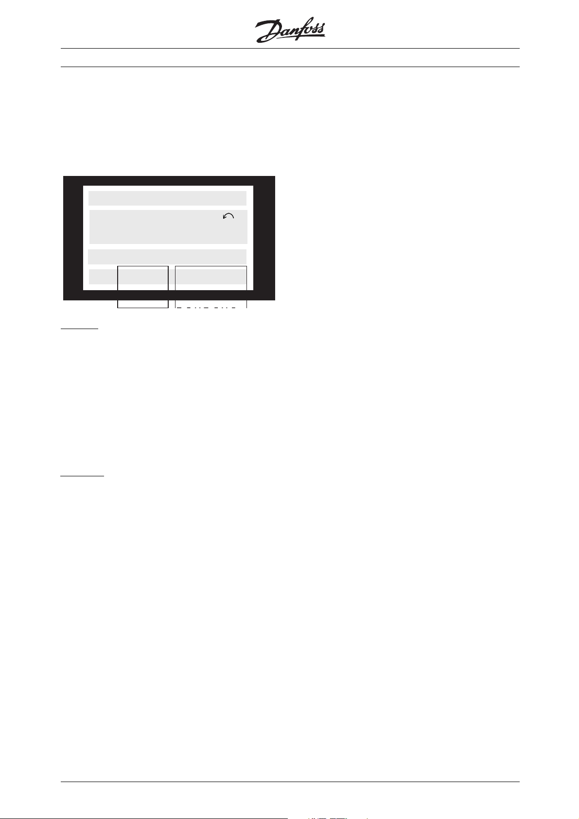
■Status Messages
Status messages appear in the 4th line of the
display, see the example.
The left part of the status line indicates the active type
of control of the VLT 500 Crane. The right part states
the present status, eg. "Running", "Stop", "Coast", etc.
80.0% 5.08A
SETUP
40.0Hz
1
REMOTE RUNNING
VLT® 5000 Crane
LOCAL
Left part:
Crane: The drive profile for the frequency converter
is Crane profile (Parameter 512)
Rem: Remote has been selected in parameter 002,
the reference is set via the control terminal or via
the serial communication. The drive profile for the
frequency converter is FC-profile (parameter 512)
Local: Local has been selected in parameter
002, the reference is set in parameter 003.
The drive profile for the frequency converter
is FC-profile (parameter 512)
R
ight part:
Ramping: The output frequency is now changed
according to the present ramp
Coast: The motor has been coasted
via a coast signal
Qstop: The motor has been stopped
via a qstop signal
Stop: The motor has been stopped via a stop signal
Stand by: The frequency converter will start
when it receives a start signal via digital input
or the serial communication port.
Run jog: Jog has been enabled via LCP digital
input or the serial communication port.
Running: The motor speed corresponds
to the resulting reference
Br. Error: Stop: A brake release error has been
detected and the motor is coasted.
Br. Error: Low: A brake activate error has been
detected and the frequency converter is lowering.
STOP
86
MG.50.N4.02 - VLT is a registered Danfoss trademark
Page 88
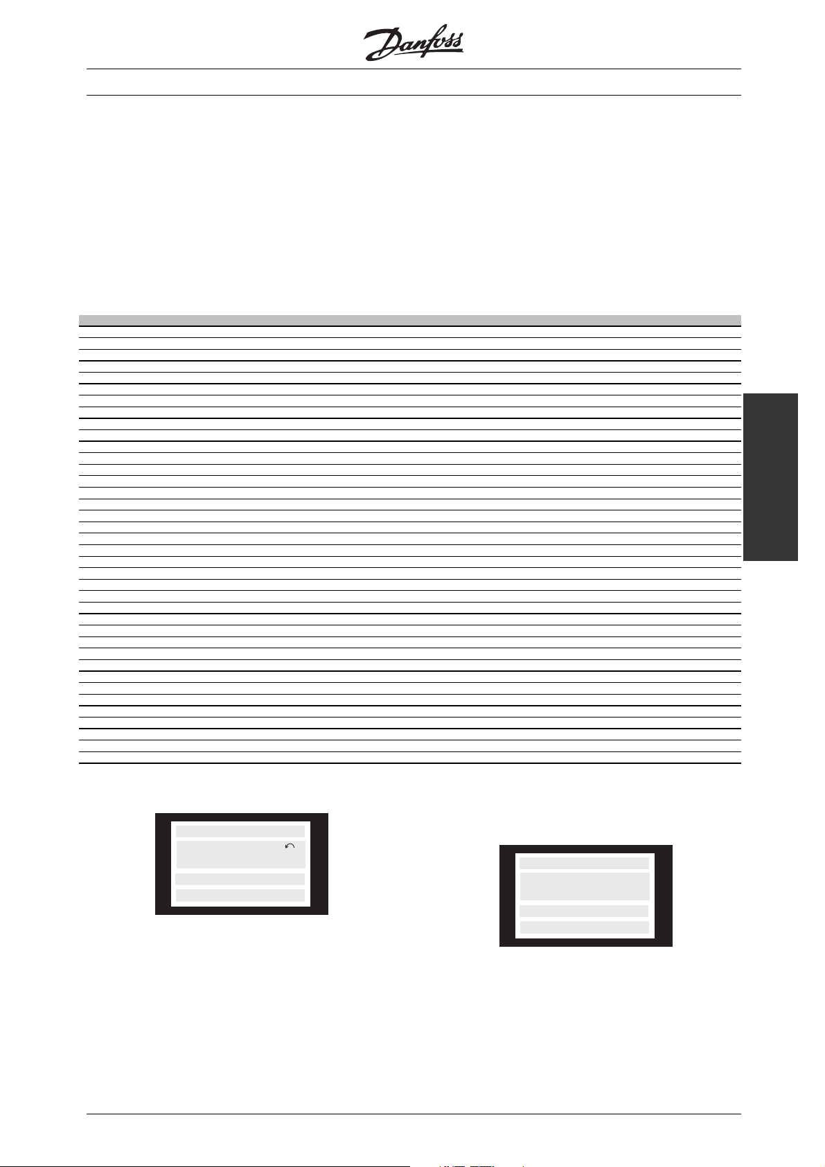
VLT® 5000 Crane
■List of Warnings and Alarms
The table shows the various warnings and alarms
and indicates whether the fault locks the frequency
converter. After Trip locked, the mains supply
must be cut and the fault must be corrected.
Reconnect the mains supply and reset the frequency
converter before being ready
No. Description Warning Alarm Locked
1 10VOLTLOW X
2LIVEZEROERROR X X
3NOMOTOR X
4 MAINS PHASE LOSS X X X
5 DC LINK VOLTAGE HIGH X
6 DC LINK VOLTAGE LOW X
7DCLINKOVERVOLT X X X
8 DC LINK UNDERVOLT X X X
9INVERTERTIME X X X
10 MOTOR TIME X X X
11 MOTOR THERMISTOR X X X
12 TORQUE LIMIT X X
13 OVER CURRENT XX
14 EARTH FAULT XX
15 SWITCH MODE FAULT XX
16 CURR. SHORT CIRCUIT XX
17 STD_BUS-TIMEOUT X X X
19 EE ERROR POWER CARD X
20 EE ERROR CTRL. CARD X
23 BRAKE TEST FAILED X
25 BRAKE RESISTOR FAULT X
26 BRAKE POWER 100% X X
27 BRAKE IGBT FAULT X
29 HEAT SINK OVER TEMP. XX
30 MISSING MOT.PHASE U X
31 MISSING MOT.PHASE V X
32 MISSING MOT.PHASE W X
35 MOTOR NOT READY X
36 MAINS FAILURE X X X
37 INVERTER FAULT XX
43 BRAKE FAULT XX
44 ENCODER FAULT XX
45 LOAD FAULT XX
46 WATCHDOG FAULT XX
47 FLASH FAULT XX
48 TRACKING FAULT X
49 BRAKE RELEASE FAULT X
50 BRAKE ACTIVATE FAULT X
Whereever a cross is placed under both Warning
and Alarm, this indicates either that a warning
precedes the alarm or that it is possible to program
whether a given fault is to result in a warning or
an alarm. This is possible, eg. in parameter 404
Brake Check. After a trip, alarm and warning will
flash, but if the fault is removed, only alarm will
flash. After a reset, the frequency converter will
be ready to start operation again.
Crane
All About VLT 5000
■Warnings
10 VOLT LOW
SETUP
WARN. 1
1
The display flashes between normal state and
warning. A warning comes up on the first and
second line of the display.
MG.50.N4.02 - VLT is a registered Danfoss trademark
Alarm messages
TRIP (RESET)
SETUP
ALARM:12
TORQUE LIMIT
1
Thealarmcomesupinthe2. and3. lineofthedisplay.
Please note that in the tables on the following
pages, some numbers are marked with a (w) or
an (a). This indicates a warning and an alarm,
respectively. Where nothing is indicated, the number
is both a warning and an alarm.
87
Page 89

Alarm/warning limits:
VLT 5000 Crane 3 x 400-500 VAC
Undervoltage 402 VDC
Voltage warning low 423 VDC
Voltage warning high 801/840 VDC (w/o brake - w/brake)
Overvoltage 855 VDC
■Warnings and Alarms, 1-6
VLT® 5000 Crane
Warn-
ing/Alarm
number
1(w) 10 Volt Low The 10 Volts voltage from terminal 50 on the control
2 Live Zero Error The current signal on terminal 58 or the voltage
3(a) No Motor The motor c
4 Mains Phase
5(w) DC Link Voltage
6(w) DC Link Voltage
Display Description How to Handle
card is below 10 Volts
rminal 53 is less than 50% of the value
heck function (see parameter 122)
Loss
High
w
Lo
signal on te
set in parameter 353/309
indicates that no motor has been connected to the
output of the frequency converter
Phasemissingonthesupplysideormains
imbalance is too high
The intermediate circuit voltage (DC) is higher than
the overvoltage limit of the control system. The
quency converter is still active
fre
The intermediate circuit voltage is below the
dervoltage limit of the control system. The
un
frequency converter is still active
Remove some of the load from terminal 50,
as the 10 Volts supply is overloaded. Max.
17 mA/min. 590
Check the wires to terminals 53 and 58
Check the m
Check the supply voltage to the frequency
converter
Check brake resistor connection
Check the supply voltage to the frequency
nverter
co
otor connection
88
MG.50.N4.02 - VLT is a registered Danfoss trademark
Page 90

■Warnings and Alarms, 7-16
VLT® 5000 Crane
Warn-
ing/Alarm
number
7 DC Link Overvolt If the intermediate circuit voltage (DC) exceeds the
8 DC Link
9 Inverter Time The electronic, thermal inverter protection reports
10 Motor Time According to the electronic thermal protection
11 Motor Thermistor The motor is too hot and the thermistor connection
12 Torque Limit Thetorqueishigherthanthevalueinparameter
13 Overcurrent The inverter peak current limit (approx. 200% of
14 (a) Earth Fault There is a discharge from the output phases to
15 (a) Switch Mode
16 (a) Curr. Short
Display Description How to Handle
inverter overvoltage limit, the frequency converter
will trip.
Furthermore, the voltage will be stated in the
display.
If the intermediate circuit voltage (DC) drops below
Undervolt
Fault
circuit
the inverter lower voltage limit (see table, previous
page), it will be checked whether 24 V power
supply is connected. If no 24 V power supply is
connected, the frequency converter will trip after a
given time depending on the unit. Furthermore, the
voltage will be stated in the display.
that the frequency converter is about to cut out
because of an overload (too high current for too
long). The counter for electronic, thermal inverter
protection gives a waring at 98% and trips at 100%,
while giving an alarm. The frequency converter
c
annot be reset until the counter is below 90%..
(ETR), the motor is too hot. Parameter 128 allows a
choice of whether the frequency converter is to give
a warning or an alarm when the counter reaches
100%. The fault is that the motor is overloaded by
more than 100% for too long.
has been disconnected. Parameter 128 allows a
choice of whether the frequency converter is to
give a warning or an alarm.
221 (in motor operation) or the torque is higher
than the value in parameter 222 (in regenerative
operation)
the rated curent) has been exceeded. The warning
will last approx. 1-2 seconds, following which the
frequency converter will trip, while giving an alarm
earth, either in a cable between the frequency
converter and the motor or in the motor itself
Fault in the switch mode power supply (internal +/-
15 V supply)
There is a short-circuiting on the motor terminals or
in the motor itself
The fault can be eliminated by connecting a
brake resistor (if the frequency converter has
an integral brake chopper, EB or SB)
Check whether the supply voltage matcehs
the frequency converter, see Technical Data
The problem is avoided by ensuring that the
frequency converter will not be overloaded by
more than 100% for too long
Crane
All About VLT 5000
Check the load and that motor parameters
102-106 have been set correctly
Check the load and that the thermistor has
been correctly connected between terminal
53 or 54 (analogue voltage input) and terminal
50 (+ 10 Volts supply)
Check load, acceleration and decelaration
ramps. Furthermore, check that motor
parameters 221-222 have been set correctly
Turn off the frequency converter and check
whether the motor shaft can be turned
and whether the motor size mathces the
frequency converter
Turn off the frequency converter and remove
the earth fault
Contact your Danfoss supplier
Turn off the frequency converter and remove
the short-circuit
MG.50.N4.02 - VLT is a registered Danfoss trademark
89
Page 91

■Warnings and Alarms, 19-27
VLT® 5000 Crane
Warn-
ing/Alarm
Number
19 (w) EE Error Power
20 (w) EE Error CTRL
23 Brake Test Failed The brake resistor test is only run after power-up. If
25 (w) Brake Resistor
26 (w) Brake Pwr Warn
27 (w) Brake IGBT Fault The brake transistor is monitored during operation
Display Description How to Handle
There is a fault on the power card EEPROM. The
Card
Card
Fault
100%
frequency converter continues to function, but is
likely to fail at the next power-up.
There is a fault in the EEPROM on the control card.
The frequency converter will continue to function,
but is likely to fail at the next power-up
Warning has been selected in parameter 404, the
warning appears when the brake test finds a fault.
If Tr ip has been selected in parameter 404, the
frequency converter will trip when the brake test
finds a fault.
The brake resistor monitored during operation and if
it short-circuits, the brake function is disconnected
and the warning appears. The frequency converter
is still able to work, although without the brake
function.
The power transmitted to the brake resistor is
calculated as a percentage, as a mean value over
the last 120 sec., on basis of the resistance value
of the brake resistor (parameter 401) and the
intermediate circuit voltage. The warning is active
when the dissipated braking power is higher than
100%. If Tr ip has been selected in parameter 403,
the frequency converter will cut out while giving
the alarm.
and if it short-circuits, the brake function is
disconnected and the warning appears. The
frequency converter is still able to run, but since
the brake transistor has short-circuited, substantial
power will be transmitted to the brake resistor,
even if it is inactive.
Contact your Danfoss supplier
Contact your Danfoss supplier
The brake test may fail for the following
reasons:
No brake resistor connected or fault in the
connections; defective brake resistor or
defective brake transistor. A warning or alarm
means that the brake function is still active
Turn off the frequency converter and replace
the brake resistor
Check parameter 403 and the regenerative
load
Turn off the frequency converter and remove
the brake resistor, see warning below
90
Warning: There is a risk of substantial power
being transmitted to the brake resistor if
the brake transistor has short-circuited
MG.50.N4.02 - VLT is a registered Danfoss trademark
Page 92

■Warnings and Alarms, 29-49
VLT® 5000 Crane
Warn-
ings/Alarm
numbers
29 (w) Heat Sink Over Temp For IP20/IP 00, the cut-out temperature if the heat
30 (a) Missing Mot.Phase U Motor phase U between frequency converter and
31 (a) Missing Mot.Phase V Motor phase V between frequency converter and
32 (a) Missing Mot.PhaseWMotor phase W between frequency converter and
35 (w) Motor Not Ready The drive was unable to finish the starting sequence
37 (a) Inverter Fault IGBT or the power card is defective Contact your Danfoss supplier
43 (a) Brake Fault A fault has arisen on the brake chopper. The text
44 (a) Encoder fault The encoder signal is interrupted from terminal 73,
45 (a) Load fault An overload has occurred on one or both of the
46 (a) Watchdog fault An internal error has occurred Contact your Danfoss supplier
47 (a) Flash fault An internal error has occurred Contact your Danfoss supplier
48 (a) Tracking fault Load is dropping faster than expected Check mechanical brake
49 (w) Brake release fault Fault when releasing the brake (open).
50 (w) Brake activate fault Fault when activating the brake (close) Remove the start signal
Display Description How to Handle
Decrease ambient temperature and
sink is 90°C. The tolerance is +/- 5°C.
motor is missing
motor is missing
motor is missing
(pre-magnetisation and start torque) within 5 sec.
shown in the display indicates a fault message.
The figure in square brackets is the fault code that
canbeseeninthefaultlog,parameter615
74, 75, 76, 77 or 78
load contacts and the speed is too high to hold the
load. The overload causes a trip
check fans
Turn off the frequency converter and
check motor phase U
Turn off the frequency converter and
check motor phase V
Turn off the frequency converter and
check motor phase W
Check the motor connection
[0] The brake resistor check carried out
during power-up indicates that the brake
has been disconnected. Check whether
the brake has been connected correctly
and that it has not been dispconnected
[1] The brake output has short-circuited.
Replace the brake resistor
[2] The brake IGBT has short-circuited.
This fault means that the unit is not able
to stop the brake and that, consequently,
the resistor is constantly being energized
Check the connections
Startupagainwithreducedspeed
Crane
All About VLT 5000
MG.50.N4.02 - VLT is a registered Danfoss trademark
91
Page 93

VLT® 5000 Crane
■Trouble-shooting
Symptom How to handle
1. Motor runs unevenly If the motor runs unevenly, but no fault is given, this may be because
the frequency converter has been wrongly set.
Adjust the motor data settings.
Contact Danfoss if the new setting does not make the motor run
evenly
2. Motor does not run Check if there is a backlight in the display.
If there is a backlight, please check if a fault message is displayed.
If yes, please consult the Warnings-section, if no, please refer to
symptom 5.
If there is no backlight, check if the is connected to mains supply. If
yes, please refer to symptom 4.
3. Motor does not brake Please refer to symptom 6.
4. No message or backlight in
display
5. Motor stopped, light in display,
but no fault report
Check if the prefuses for the have blown.
If yes, call Danfoss for assistance.
If no, check if the control card is overloaded.
If so, disconnect all control signal plugs on the control card and
check if the fault disappears.
If yes, make sure that the 24 V supply is not short-circuited.
If no, call Danfoss for assistance.
Start the by pressing [START] on the control panel.
Check if the display is frozen, ie. the display cannot be changed
or is indefineable.
If yes, check if screened cables have been used and are connected
correctly.
If no, check that the motor is connected and that all motor phases
are OK.
The must be set to run using local references:
Parameter 002 = Local operation
Parameter 003 = desired reference value
Parameter 512 = FC Profile
Connect 24 V DC to terminal 27.
The reference is changed by pressing ’+’ or ’-’.
Is the motor running?
If yes, check whether control signals to the control card are OK.
If no, call Danfoss for assistance.
92
MG.50.N4.02 - VLT is a registered Danfoss trademark
Page 94

Symptom How to handle
6. VLT 5000 Crane trips,
"Overvoltage" is displayed and
motor does not brake
Check if the green LED "READY" on the control card is ready.
If yes, check if the yellow and red LEDs "braking" and "overload" on
the control card are active during braking period.
If yes, check if the brake resistor and its connection are OK.
If yes, call Danfoss for assistance.
If the "READY" LED is NOT active check if the connections to the
brake control card are OK, then follow the steps from checking the
"braking" and "overload" LEDs and forward.
VLT® 5000 Crane
7. Fault at start (Warning "Brake
fault 2")
Check if the system brake is correctly connected.
If no, correct the system brake connection.
If yes, check if the encoder is correctly connected.
If this is not the case, correct the encoder connection, otherwise
call Danfoss for assistance.
Appendix
MG.50.N4.02 - VLT is a registered Danfoss trademark
93
Page 95

■Derating for Ambient Temperature
The ambient temperature (T
AMB,MAX
temperature allowed. The average (T
) is the maximum
AMB,AVG
)is
measured over 24 hours and must be at least 5ºC lower.
NB!:
VLT 5000 Crane is already derated for
operational temperature (55° T
and 50° T
AMB,AVG
.
AMB,MAX
■Derating for air pressure
Below 1000 m derating is not necessary.
Above 1000 m the ambient temperature (T
or max. output current (I
) must be derated in
MAX
AMB
accordance with the diagram below:
1. Derating of output current versus altitude
2. Derating of max. T
versus altitude at
AMB
100% output current.
VLT® 5000 Crane
)
■Derating for Running at Low Speed
When a motor is connected to a frequency
converter, it is necessary to check whether the
cooling of the motor is adequate.
At low RPM values, the motor fan is not able to
supply the required volume of air for cooling. This
problem occurs when the load torque is constant
(e.g. a conveyor belt) across the regulating range.
The reduced ventilation available decides the size of
thetorquethatcanbepermittedunderacontinuous
load. If the motor is to run continuously at an RPM
value lower than half the rated value, the motor must
be supplied with additional air for cooling.
Instead of such extra cooling, the load level of
the motor can be reduced. This can be done by
choosing a bigger motor. However, the design of
the frequency converter sets limits as to the size
of motor that can be connected to it.
94
MG.50.N4.02 - VLT is a registered Danfoss trademark
Page 96
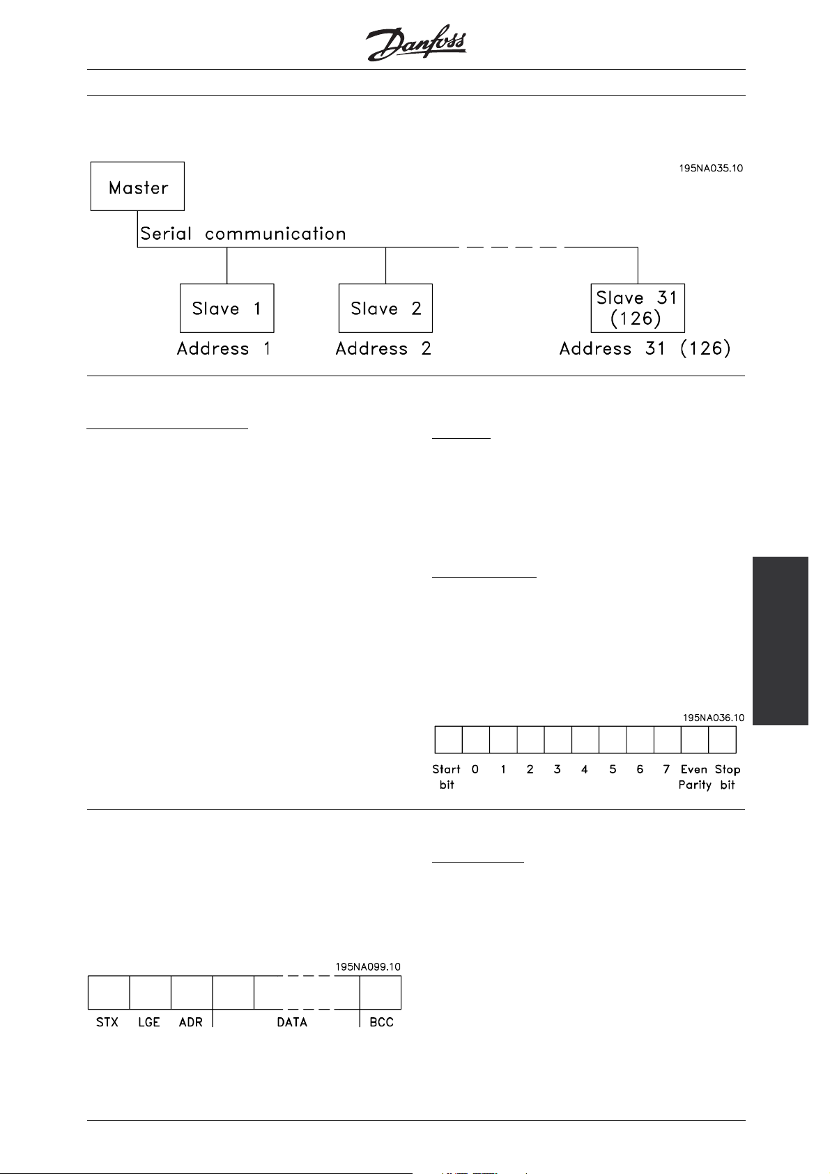
■Serial Communication
■Telegram Communication
ontrol and reply telegrams
C
Telegram communication in a master-slave system is
controlled by the master. A maximum of 31 slaves (
5000 Crane) can be connected to one master, unless
a repeater is used. If a repeater is used, a maximum
of 126 slaves can be connected to one master.
The master sends control telegrams addressed to the
slaves and awaits reply telegrams from these. The
response time of the slaves is maximum of 50 ms.
A slave responds by sending a reply telegram
when it has received telegram with corr
STX, LGE, ADR and BCC..
ect
VLT
VLT® 5000 Crane
B
roadcast
A master can send the same telegram at the same
time to all slaves connected to the bus. In such
broadcast communication, the slave does not send
a reply telegram to the master, provided the telegram
has been correctly received. Boradcast communication
is set up in the address format (ADR).
C
ontent of a byte
Each transferred character begins with a start bit.
Subsequently, 8 data bits are transferred. Each
character is secured via a parity bit, which is set to
"1"whenthereisevenparity(i.e. anevennumber
of binary 1’sinthe8databitsandtheparitybit
combined). A character ends with a stop bit, thus
consisting of a total of 11 bitsl.
Appendix
■Telegram Build-up
Each telegram begins with a start byte (STX) = 02
Hex, followed by a byte that states the telegram
length (LGE) and a byte that states the address of the
frequency converter (ADR). Then follows a number of
data bytes (variable, depending on telegram type). The
telegram ends with a data control byte (BCC).
MG.50.N4.02 - VLT is a registered Danfoss trademark
Telegram timing
The speed of communication between a master and
a slave depends on the baud rate. The baud rate
of the frequency converter must be the same as the
baud rate of the master and is selected in parameter
501 Baud rate. After a reply telegram from the slave,
there must be a minimum pause of 2 characters
(22 bits) before the master is able to send another
telegram. At a baud rate of 9600 baud, there must
be a minimum pause of 2.3 msec. After the master
95
Page 97
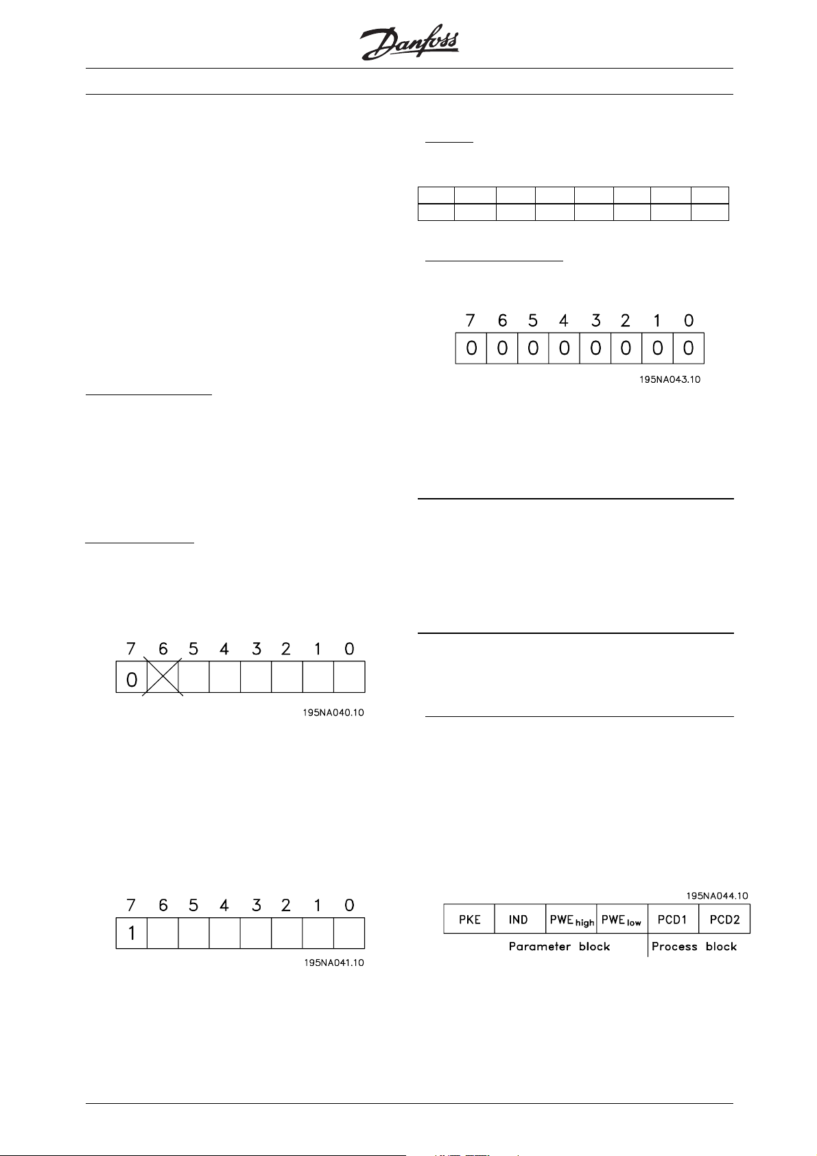
VLT® 5000 Crane
has completed the telegram, the response time of the
slave back to the master will be max. 20 msec. and
there will be a minimum pause of 2 characters.
Pause time, min. 2 characters
Response time, min. 2 characters
Response time, max. 20 msec.
The time between individual characters in a telegram is
not to exceed 2 characters and the telegram must be
completed within 1.5 times the rated telegram time.
If the baud rate is 9600 baud and the telegram
length is 16 characters, the telegram must be
completed within 27.5 msec.
T
elegram length (LGE)
The telegram length is the number of data bytes plus
the address byte ADR plus the data control byte BCC.
Telegrams with 4 data bytes have a length of:
LGE=4+1+1=6bytes
Telegrams with 12 data bytes have a length of:
LGE=12+1+1=14bytes
E
xample
A telegram is sent to frequency converter address
22 using address format 1-31:
7 6 5 4 3 2 1 0
0 0 0 1 0 1 1 0
Data control byte (BCC)
The data control byte is the EXOR-sum of the entire
telegram. It is best explained by means of an example:
Before the first byte of the telegram is received, BCC is 0.
When the first byte has been received:
BCC
NEW
=BCC
EXOR "first byte"
OLD
(EXOR = exclusive-or gate)
BCC
OLD
=00000000
EXOR
1. byte =00000010(02H)
BCC
NEW
=00000010
V
LT address (ADR)
Two different address formats are used, in which
the address range of the frequency converter is
either from 1-31 or from 1-126.:
1 Address format 1-31
The byte for this address range has the following profile:
Bit 7 = 0 (address format 1-31 active)
Bit 6 is not used
Bit 5 = 1: Broadcast, address bits (0-4) are not used
Bit 5 = 0: No Broadcast
Bit 0-4 = Frequency converter address 1-31
2. Address format 1-126:
Thebyteforthe1-126addressrangehas
the following profile:
Each subsequent byte gates with BCC
and produces a new BCC
BCC
OLD
=00000010
NEW
, e.g.:
OLD
EXOR
2ndbyte =11010110(D6H)
BCC
NEW
=11010100
The result after the latest incoming byte is BCC.
■Databytes
The build-up of data blocks depends on the type
of telegram. There are three types of telegram and
the telegram type applies to both control telegram
(master→slave) and reply telegram (slave→master).
The three types of telegrams are the following:
1. Parameter block, used for transferring parameters
between master and slave. The data block has 12
bytes 6 words and also contains the process block.
EXOR
Bit 7 = 1 (address format 1-126 active)
Bit 0-6 = Frequency converter address 1-126
Bit 0-6 = 0 Broadcast
The slave sends the address byte back to the master
in the reply telegram in unchanged form.
96
2. Process block, built up as a data block with
four bytes (2 words), covering:
- Control word and reference value (from
master to slave)
- Status word and present output frequency
(from slave to master)
MG.50.N4.02 - VLT is a registered Danfoss trademark
Page 98

VLT® 5000 Crane
PCD 1 PCD 2
Process block
3. Text block, used for reading or writing
texts via the data block.
PKE IND Ch1 Ch2 ChnPCD1 PCD2
Te xt b lo ck Process
block
1. Parameter bytes
Commands and replies (AK)
Bits no. 12-15 are used for transmitting commands
from master to slave and the slave’s processed
replies back to the master.
Parameter commands master⇒slave
Bit no.
15 14 13 12 Parameter command
0000Nocommand
0 0 0 1 Read parameter value
0 0 1 0 Write parameter value in RAM
(word)
0 0 1 1 Write parameter value in RAM
(double word)
0 1 0 0 Read parameter description
element
1 1 0 1 Write parameter value in RAM
and EEprom (double word)
1 1 1 0 Write parameter value in RAM
and EEprom (word)
1111Readtext
Reply slave⇒master
Bit no. Response
15 14 13 12
0000Noresponse
0 0 0 1 Parameter value transferred
(word)
0 0 1 0 Parameter value transferred
(double word)
0 0 1 1 Parameter description element
transferred
0 1 1 1 Command cannot be performed
1 1 1 1 Text transferred
If the command cannot be executed, the slave will
send this reply: 0111 and give the following error
message in the parameter value (PWE):
Error code
Error message
(reply 0111)
0 The parameter number used
does not exist
1 There is no write access to the
parameter called
2 Data value exceeds
the parameter limits
3 The sub index used
does not exist
4 The parameter is not the array type
5 The data type does not ma
tch the
parameter called
17 Data change in the pa
rameter called
is not possible in
the present mode of the frequency
converter.
Eg. someparameters can only be
changed when the
motor has stopped
130 There is no bus access to the
parameter called
131 Data change is not possible because
factory Setup is sel
Parameter number (PNU)
Bits no. 0-10 are used for transmitting parameter
numbers. The function of a given parameter
can be seen from the parameter description
in the Programming section.
I
ndex
ected
Appendix
MG.50.N4.02 - VLT is a registered Danfoss trademark
97
Page 99
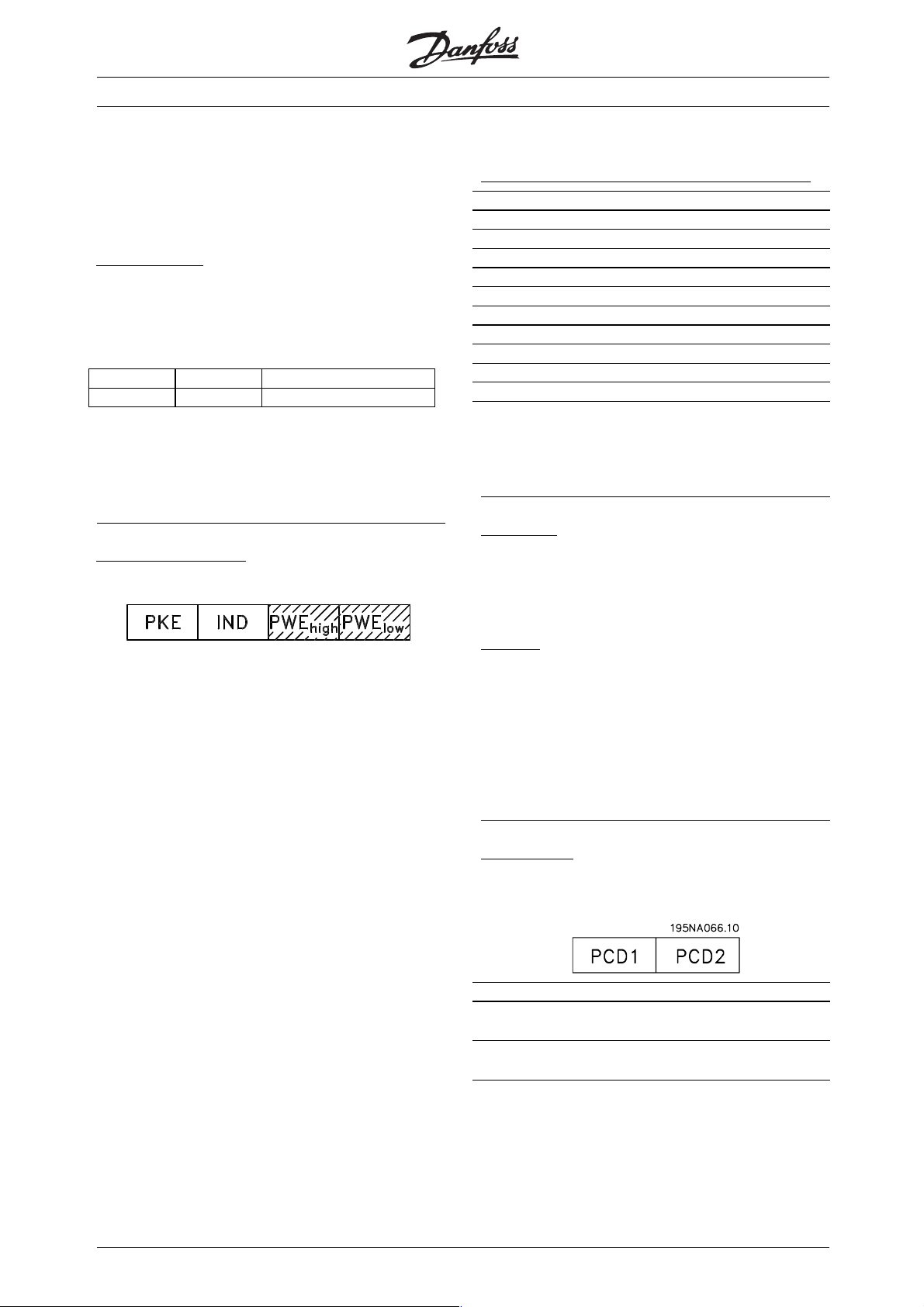
Index is used together with the parameter number
for read/write-access to parameters with an index,
such as parameter 615 Error code.
Index has 2 bytes - a lowbyte and a highbyte. However,
only the lowbyte is used. See example below:
xample - index
E
The first error code (index [1]) in parameter 615
Error code must be read.
PKE = 1267 Hex (read parameter 615 Error code).
IND = 0001 Hex - Index no. 1.
1267 H 0001 H
PKE IND PWE
VLT® 5000 Crane
D
ata types supported by the frequency transformer:
Data types Description
3Signed16
4Signed32
5 Unsigned 8
6 Unsigned 16
7 Unsigned 32
9 Visible string
10 Byte string
13 Time difference
33 Reserved
35 Bit sequence
The frequency converter will respond in the
parameter value (PWE) block by means of an
error code with a value from 1-99.
Parameter value (PWE)
The parameter value block consists of 2 words
(4 bytes) and its value depends on the command
given (AK). If the master enquires about parameter
value, the PWE block contains no value.
If a parameter value is to be changed by the
master (write), the new value is entered in the
PWE block and sent to the slave.
The transferred text corresponds to the figures given
in the parameter descriptions in the manual. Eg.
parameter 001 Language, where [0] corresponds to
English, and [2] corresponds to French.
However, parameters with data type 9 (text string)
are excepted, as this is transferred as an ASCII text
string. When a text string is transferred (read), the
telegram length is variable, since the texts have different
lengths. The telegram length is stated in the 2nd byte
of the telegram, called LGE. Parameters 621-631
(nameplate data) have data type 9 (text string).
Unsigned means that there is no sign included
in the telegram.
Conversion:
The different attributes for each parameter can be seen
in the section on factory settings. Since a parameter
value can only be transferred as a whole number, a
conversion factor must be used to transfer decimals.
E
xample:
Parameter 202 Output speed high limit has a
conversion factor of 0.1. If you wish to preset the
minimum frequency to 10 Hz, the value 100 must
be transferred, as a conversion factor of 0.1 means
that the value transferred is multiplied by 0.1. The
value 100 will thus be perceived as 10.0. See also
Conversion and Unit of measurement.
Process bytes
The process byte block is divided into two blocks each
of 16 bits, which always come in the sequence stated.
PCD 1 PCD 2
Control telegram
(master⇒slave)
Control telegram
(slave⇒master)
Control word Reference-
value
Status word Present outp.
frequency
98
MG.50.N4.02 - VLT is a registered Danfoss trademark
Page 100

VLT® 5000 Crane
■Control Word in Crane Profile
ontrol word in Crane profile (parameter
C
512 = crane profile)
The control word is used for sending commands from
a master, eg. a PC, to a slave (frequency converter).
Bit Bit = 0 Bit = 1
00 Load contact 1
No function
inverse
01 Load contact 2
No function
inverse
02 No function Positioning
03 Coasting inverse No function
04 Quick stop inverse No function
05 Ramp stop Start lowering
06 Ramp stop Start hoisting
07 No function Reset
08 No function
09 Gear low Gear high
10 Data not valid Data valid
11 No function Relay 01 activated
12 No function Relay 04 activated
13 No function
14 No function
15 No function
Bit 02 = "0" means no reduced speed. Bit 02
= "1" means reduced speed.
it 03, Coasting inverse/No function
B
Please refer to Control word in FC profile.
it 04, Quick stop inverse/No function
B
Please refer to Control word in FC profile.
B
it 05, No function/Start lowering
Makes the motor turn to lower the load opposite of the
direction set in parameter 707, Hoist direction.
Bit 05 = "0" leads to a stop if bit 06 = "0". Bit 05 = "1"
leads to start if bit 06 = "0". Otherwise it leads to a stop.
Bit 05 Bit 06
Stop 0 0
Stop 1 1
Hoisting 0 1
Lowering 1 0
Bit 06, No function/Start hoisting
Makes the motor turn to hoist the load according to the
direction set in parameter 707, Hoist direction.
Bit 06 = "0" leads to a stop if bit 05 = "0". Bit 06 = "1"
leads to start if bit 05 = "0". Otherwise it leads to a stop.
B
it 07, No function/Reset
Please refer to Control word in FC profile.
it 09, Gear low/Gear high
B
Enables gear low or high. Bit = "0" is low
gear. Bit = "1" is high gear.
Appendix
NB!:
In Crane profile bit 04 Q stop is the only choice
for logic OR, logic AND and logic BUS.
B
it 00, Load contact 1 inverse/No function
Bit 00 = "1" means no speed reduction.
B
it 01, Load contact 2 inverse/No function
Bit 01 = "0" leads to further descreased speed (
parameter 702) if bit 00 = "0". Otherwise it leads to
a Trip. Bit 01 = "1" means no speed reduction.
Bit 00 Bit 01
Load high 0 0
Load low 0 1
Trip 1 0
No
11
function
Bit 02, No function/Positioning
Makes the motor turn with reduced speed
according to parameters 106, Motor Nominal
Speed, and 205, Max. reference.
B
its 10-12
Please refer to Control word in FC profile.
MG.50.N4.02 - VLT is a registered Danfoss trademark
99
 Loading...