


VLT® types 5001-5011
■ Description of the brake system ...................Page 3
■ Application - conveyor belt ........................... Page 3
General formulas ........................................... Page 4
Brake performance examples ......................Page 4
■ Selection of brake resistor ............................Page 5
■ How to setup the brake function ..................Page 6
Basic setup ...................................................Page 6
Power monitoring ..........................................Page 6
Brake check .................................................Page 7
Protection properties ....................................Page 7
Readout of brake power...............................Page 7
DC hold ......................................................... Page 7
■ Installation .....................................................Page 7
Mechanical ................................................... Page 7
Electrical ....................................................... Page 8
EMC (twisted cables/shielding) ................. Page 8
■ Dimensions ................................................... Page 9
Warning:
Do not touch the brake resistors
during braking. They can be very
hot.
MI.50.S1.02 – VLT is a registered Danfoss trademark 1

VLT® types 5001-5011
■■
Introduction
■
■■
The flatpack brakeresistors for the VLT 5000 series is
a safe and compact solution for the customer.
At a constant load and free convection the resistor is
selfprotecting as a fuse. This means short circuit
proof, no fault to frame, no melting of casing and self
extinguishing. The casing is made of anodized
aluminum and is IP54 tight.
■■
Description of the brake system
■
■■
When the speed of a frequency converter is reduced, the motor acts as a generator and brakes.
When a motor acts as a generator, it supplies energy
to the intermediate circuit in the frequency converter.
The brake resistor loads the intermediate circuit, ensuring that the brake power is absorbed by the
brake resistor.
If a brake resistor was not used, the intermediate circuit voltage of the frequency converter would continue to increase, until it cuts out for protection.
The advantage of using a brake resistor is that it
enables braking of heavy load quickly, e.g. on a conveyor belt.
With the compact flatpack resistor, it is possible to
mount the resistor on the rear of a VLT 5000
bookstyle frequency converter.
In addition, VLT5000 incorporates brake monitoring
to ensure that the average power dissipated to the
brake resistor does not exceed a given limit. The
brake monitor calculates the mean brake power
within the last 120 seconds and compares this
value with a programmed limit. If the limit is exceeded the drive can give a warning or trip. Monitoring of short circuiting of the brake resistor or
brake IGBT and disconnection of the brake resistor
is also possible.
Increased performance at low speeds can be
achieved by using the DC brake in VLT5000.
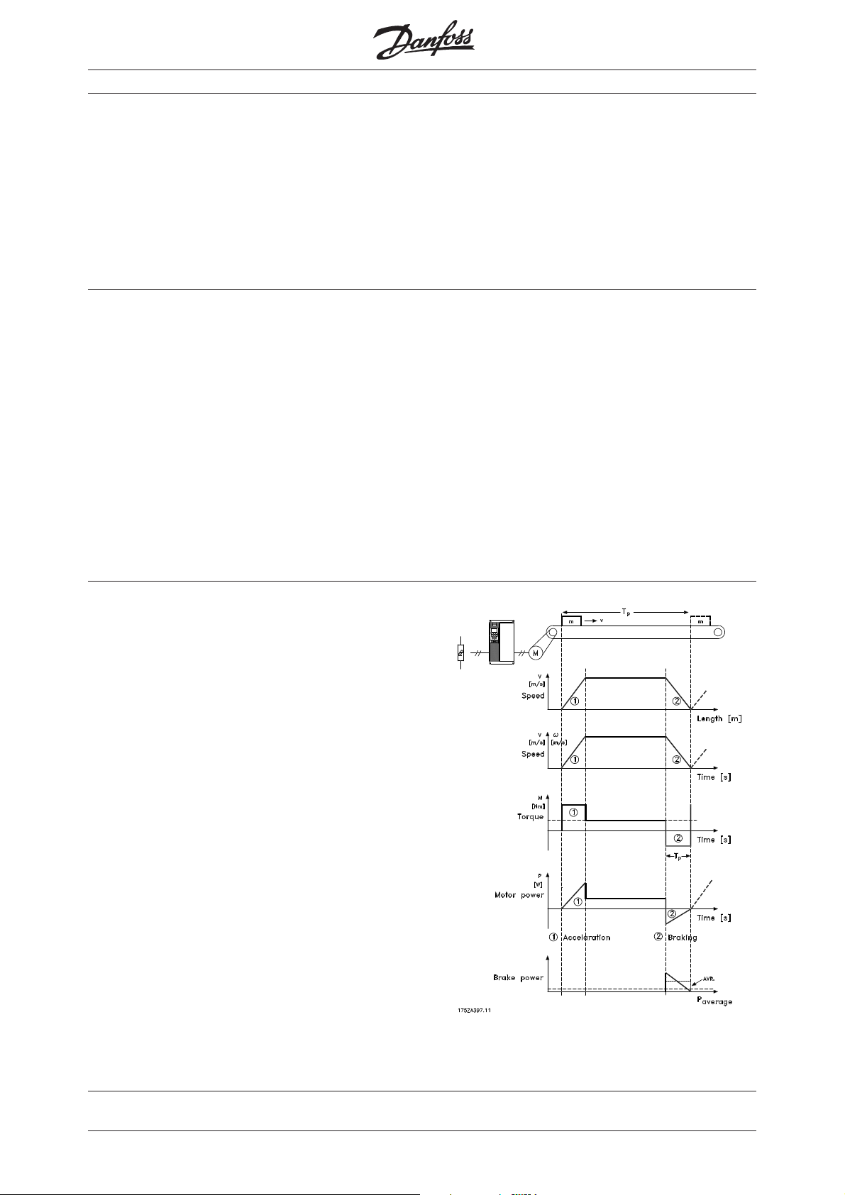
Application - conveyor belt
■■
■
■■
The brake resistor program covered in this instruction
is for horizontal conveyor applications. The resistors
are chosen for use with small drives, this means up
to VLT5011.
The premises for the application is:
● The energy of the system is assumed to be deter-
mined by two times the motor inertia.
● Values for braking are calculated at 160% torque.
Figure 1 shows the relation between the braking
power and the acceleration/braking of the conveyor
belt. During braking the motor power is negative,
since the torque on the motor shaft is negative. The
braking power is to be dissipated in the brake resistor, and corresponds almost to the negative motor
power taking the losses into the motor and VLT frequency converter into account.
Figure 1
Typical characteristic of a
horizontal brake application
MI.50.S1.02 – VLT is a registered Danfoss trademark 3
■■
■
■■
General fomulas
The general formulas for calculation of the brake in a
system are stated below.
An example is shown with the following values:
Motor inertia: j = 0.0021 kgm2
Motor speed (at 50 Hz): n = 1500 rpm
Average power dissipated in resistor: P
Nominal motor power: P
average
= 750 W
motor
= 120 W
The kinetic energy in the system is:
2
E = ½ × j' × ω
= j × ω2 = 0.011 × j × n2 [Ws]
E = 0.011 × 0.0021 × 1500 × 1500 = 52 Ws
2
j = inertia of motor and gear box (kgm
]
j' = inertia of the system ≈ 2 × j
ω = motor speed = (n × 2 × π)/60 [rad/s]
n = motor speed [rpm]
The maximum number of stops per time unit
for the resistor is calculated as:
f
= P
stop
resistor/Esystem
f
= 120/52 = 2.3 s-1 = 138,5 min
stop
[s-1]
-1
VLT® types 5001-5011
The minimum time for stop is calculated as:
= E
t
stop
t
= 52/750 = 0.069 s
stop
P
motor
The maximum duty cycle of the system is:
Duty cycle = t
Duty cycle = 0.069 × 2.3 × 100 = 16%
The resistor values must be calculated using the formulas from the general brake instruction (resistance
based on minimum acceptable resistance). When
choosing a standard resistor, it is necessary to
choose a value higher than the calculated
240 Volt units: R
500 Volt units: R
system
/ P
motor
[s]
= nominal motor power (100% torque)
× f
stop
× 100 [%]
stop
= 111684 / P
rec
R
= 111684 / 750 = 149
rec
= 478801 / P
rec
= 478801 / 750 = 638
R
rec
motor
motor
[Ω]
[Ω]
t
.
rec
Ω
Ω
P
= Average power dissipated in the resistor [W]
resistor
■■
■
■■
Brake performance examples
The figures below show typical data for a horizontal
application. At other frequencies please use the for-
All are calculated at a nominal motor speed of
1500 rpm at 50 Hz.
mulas above to calculate the values.
P
, 120 W
average
VLT type Motor Motor System E (50Hz) Number of E (100 Hz) Number of Stop time [s] Stop time [s]
5001 0.75 0.00210 0.00420 52.0 138.5 207.9 34.6 0.069 0.277
5002 1.1 0.00320 0.00640 79.2 90.9 316.8 22.7 0.072 0.288
5003 1.5 0.00430 0.00860 106.4 67.7 425.7 16.9 0.071 0.284
5004 2.2 0.00690 0.01380 170.8 42.2 683.1 10.5 0.078 0.311
5005 3 0.00820 0.01640 203.0 35.5 811.8 8.9 0.068 0.271
5006 4 0.01200 0.02400 297.0 24.2 1188.0 6.1 0.074 0.297
5008 5.5 0.01800 0.03600 445.5 16.2 1782.0 4.0 0.081 0.324
5011 7.5 0.02300 0.04600 569.3 12.6 2277.0 3.2 0.076 0.304
P
average
VLT type Motor Motor System E (50Hz) Number of E (100 Hz) Number of Stop time [s] Stop time [s]
4 pol. inertia inertia Ws stops 1/min Ws stops 1/min (50 Hz) (100 Hz)
kg
× m × m kg × m × m from 50 Hz. from 100 Hz. 160 % torque 160% torque
, 250 W
4 pol. inertia inertia Ws stops 1/min Ws stops 1/min (50 Hz) (100 Hz)
kg
×
m × m kg × m × m from 50 Hz. from 100 Hz. 160 % torque 160% torque
5001 0.75 0.00210 0.00420 52.0 254.0 207.9 63.5 0.069 0.277
5002 1.1 0.00320 0.00640 79.2 166.7 316.8 41.7 0.072 0.288
5003 1.5 0.00430 0.00860 106.4 124.0 425.7 31.0 0.071 0.284
5004 2.2 0.00690 0.01380 170.8 77.3 683.1 19.3 0.078 0.311
5005 3 0.00820 0.01640 203.0 65.0 811.8 16.3 0.068 0.271
5006 4 0.01200 0.02400 297.0 44.4 1188.0 11.1 0.074 0.297
5008 5.5 0.01800 0.03600 445.5 29.6 1782.0 7.4 0.081 0.324
5011 7.5 0.02300 0.04600 569.3 23.2 2277.0 5.8 0.076 0.304
4
MI.50.S1.02 – VLT is a registered Danfoss trademark

VLT® types 5001-5011
■■
■
■■
Selection of a brake resistor
Danfoss brake resistors for horizontal applications are
rated to the performance mentioned in the table below.
In parameter 402 the brake power limit is set. It is
calculated as described in the manual for the VLT
5000 series. The maximum values to put in must be
calculated as follows:
2
For 200-240 V units: P=397
For 380-500 V units: P=822
× Max. dutycycle / R
2
× Max. dutycycle / R
Units for supply 200 to 240 VAC
VLT Type Motor Resistor Size Ordernumber Max. duty Max. limit in
[kW] [ohm] cycle [%] par. 402
5001 0.75 150 150 Ω 100 W 175U1005 14.0 0.15
5001 0.75 150 150 Ω 200 W 175U0989 40.0 0.43
5002 1.1 100 100 Ω 100 W 175U1006 8.0 0.13
5002 1.1 100 100 Ω 200 W 175U0991 20.0 0.32
5003 1.5 72 72 Ω 200 W 175U0992 16.0 0.36
5004 2.2 47 50 Ω 200 W 175U0993 9.0 0.31
5005 3 35 35 Ω 200 W 175U0994 5.5 0.25
5005 3 35 72 Ω 200 W 2 x 175U0992
5006 4 25 50 Ω 200 W 2 x 175U0993
5008 5.5 20 40 Ω 200 W 2 x 175U0996
5011 7.5 13 27 Ω 200 W 2 x 175U0995
*1
12.0 0.55
*1
11.0 0.70
*1
6.5 0.52
*1
4.0 0.49
[kW]
Units for supply 380 to 500 VAC
VLT Type Motor Resistor Size Ordernumber Max. duty Max. limit in
[kW] [ohm] cycle [%] par. 402
[kW]
5001 0.75 630 620 Ω 100 W 175U1001 14.0 0.15
5001 0.75 630 620 Ω 200 W 175U0982 40.0 0.43
5002 1.1 430 430 Ω 100 W 175U1002 8.0 0.13
5002 1.1 430 430 Ω 200 W 175U0983 20.0 0.32
5003 1.5 320 310 Ω 200 W 175U0984 16.0 0.34
5004 2.2 215 210 Ω 200 W 175U0987 9.0 0.29
5005 3 150 150 Ω 200 W 175U0989 5.5 0.25
5005 3 150 300 Ω 200 W 2 x 175U0985
5006 4 120 240 Ω 200 W 2 x 175U0986
5008 5.5 82 160 Ω 200 W 2 x 175U0988
5011 7.5 65 130 Ω 200 W 2 x 175U0990
*1
: Connect in parallel.
*1
12.0 0.54
*1
11.0 0.62
*1
6.5 0.54
*1
4.0 0.42
MI.50.S1.02 – VLT is a registered Danfoss trademark 5

General technical data:General technical data:
General technical data:
General technical data:General technical data:
■■
■
■■
VLT® types 5001-5011
Max. permissible operating voltage V
Insulation voltage V
Casing temperature J
B
ISO
C
≤ 700 VAC always considering
≤ 1000 VDC the self protection
≤ 4000 V
≤ 250 °C free convection
Weight m about 280 g Small 100 W
about 550 g Large 200 W
Enclosure IP54
ImpulseloadImpulseload
Impulseload
ImpulseloadImpulseload
■■
■
■■
Duty cycle [%]Duty cycle [%]
Duty cycle [%]
Duty cycle [%]Duty cycle [%]
100 W resistor100 W resistor
100 W resistor
100 W resistor100 W resistor
Duty cycle [%]Duty cycle [%]
Duty cycle [%]
Duty cycle [%]Duty cycle [%]
200 W resistor200 W resistor
200 W resistor
200 W resistor200 W resistor
Power [W]Power [W]
Power [W]
Power [W]Power [W]
Figure 2
■■
■
■■
How to setup the brake function
To use the brake function it is necessary to set up
some parameters. It is always necessary to perform
the Basic Setup. Further settings are available for
monitoring the brake power, protection of the brake
resistor and brake IGBT and readout of brake power.
Basic setupBasic setup
Basic setup
Basic setupBasic setup
To enable the brake function it is necessary to set
one parameter.
- Activate the brake function
● Set parameter 400 (Brake function/overvoltage
control) to Resistor brake [1].
Power monitoringPower monitoring
Power monitoring
Power monitoringPower monitoring
To monitor the power to the brake resistor it is nec-
essary to set the following:
- Set the value of the brake resistor
● Set parameter 401 to the present resistor
value [ohm].
- Set the limit for the power transmitted to the resistor
● Set parameter 402 to the maximum accept
able power [kW] transmitted to the resistor dur
ing 120 seconds.
Power [W]Power [W]
Power [W]
Power [W]Power [W]
- Choose the power monitoring function
● Set parameter 403 to Warning [1] or Trip [2]
● If the circuit in figure 4 is used, set parameter
323 to Brakefault [30]
The monitor function calculates the power transmitted to the brake resistor. The power is calculated on
the basis of the resistor ohm value (parameter 401),
the intermediate circuit voltage and the resistor run
ning time.
If the power transmitted over 120 seconds exceeds
100% of the monitoring limit (parameter 402) and
Warning [1] (parameter 403) has been selected, a
warning will come up on the display. The warning
will disappear when the power goes below 80%.
If Trip [2] (parameter 403) has been selected, the
converter will trip and give an alarm when the power
limit is reached.
If the power monitoring is set to Off [0]or Warning
[1], the brake function remains active, even if the
monitoring limit has been exceeded. This may
lead to thermal overload of the resistor
6
MI.50.S1.02 – VLT is a registered Danfoss trademark

VLT® types 5001-5011
Brake checkBrake check
Brake check
Brake checkBrake check
To protect the brake resistor and IGBT during
operation, it is possible to activate a brake check
function.
- Activate the brake check
● Set parameter 404 to Warning [1] or Trip [2],
depending on which level of protection You
need.
If Off [0] is selected, the brake resistor and brake
IGBT will be monitored with respect to short
circuiting during operation. In case of short circuit, a
warning will be given.
If Warning [1] is selected, the brake resistor and
brake IGBT will be monitored with respect to short
circuiting and on power-up it will be checked if the
brake resistor has been disconnected.
In case of Trip [2], the VLT frequency converter will
cut out while giving an alarm (trip locked) if the
brake resistor has short-circuited or been disconnected or if the brake IGBT has short-circuited.
It is possible to readout the result of the brake
check via the outputs 42, 45, 01 (relay) or 04 (relay).
Protective propertiesProtective properties
Protective properties
Protective propertiesProtective properties
For protection of the installation, one of the outputs
from the drive can be used to control a protection
circuit. For connections, see page 8 Electrical.
● Set one of the outputs 42, 45, 01 (relay) or 04
(relay) (parameters 319, 321, 323 or 326) to
Brake Fault [30].
If there is a fault on the brake, the output will be activated and activate the protection circuit.
Readout of brake powerReadout of brake power
Readout of brake power
Readout of brake powerReadout of brake power
To readout the brake power in the display set parameters as follows:
- Mean brake power during the latest 2 minutes.
● Set parameter 009, 010, 011 or 012 to Brake
energy/2 min [23].
- Instantaneous brake power
● Set parameter 009, 010, 011 or 012 to Brake
energy/s [24].
For large readouts set parameter 009 and for small
readout set parameters 010, 011 or 012.
DC brakingDC braking
DC braking
DC brakingDC braking
To increase brake performance at low speed, the
DC brake function can be used.
● The DC brake cuts in when the output fre-
quency is below a set cut-in frequency, and no
start signal is present.
Define a DC brake cut-in frequency.
Set parameter 127 to the desired DC brake
cut-in frequency
● or control the DC brake function by activating
digital input 27. Logical low activates the brake.
Define digital input 27 to DC brake Inverse
Set parameter 304 to DC-braking, Inverse [3]
DC braking can also be controlled via the bus. See
parameter 504.
It is possible to optimise the performance of the
DC brake by changing the parameters 125 (DC
braking current) and 126 (DC braking time).
InstallationInstallation
Installation
InstallationInstallation
■■
■
■■
MechanicalMechanical
Mechanical
MechanicalMechanical
NB!:NB!:
NB!:
The brake resistor can be installed beside the drive
using different fittings. It is possible to mount the
bookstyle drives on the enclosure of the brake resis-
NB!:NB!:
The brake resistor is to be fitted on a nonflammable material.
tor. See figure.
Figure 3
Mechanical measurements and necessary space around
MI.50.S1.02 – VLT is a registered Danfoss trademark 7

ElectricalElectrical
Electrical
ElectricalElectrical
The brake resistor must be connected to the terminals 81 and 82.
For protection of the installation, a thermal relay
should be fitted that cuts off the frequency converter if the brake current becomes too high. See
Instruction MI50Dxyy (x is the version and yy is the
language).
Alternatively the built in monitoring functions can be
used, see page 7 Protective properties. To protect
the drive and brake resistor from overload, a circuit
breaker can be placed in the mains supply. One of
the relay outputs on the VLT 5000 are setup as
alarm or warning signal and controls a shunt trip. If
an alarm or warning occurs, the mains supply will
be cut out.
VLT® types 5001-5011
Figure 4
VLT5000 with integrated monitoring
EMC (twisted cables/shielding)EMC (twisted cables/shielding)
EMC (twisted cables/shielding)
EMC (twisted cables/shielding)EMC (twisted cables/shielding)
To reduce the electrical noise from the wires between the brake resistor and the VLT frequency
converter, the wires must be twisted.
For enhanced EMC performance a metal screen
can be used.
Figure 5
8
MI.50.S1.02 – VLT is a registered Danfoss trademark

■■
■
■■
Dimensions
All dimensions in mm.
VLT® types 5001-5011
175U0003
Wide - 2 resistors
175U0004
Slim - 2 resistor
A 90 130 90
175U0002
Slim - 1 resistors
Figure 6
B 65 65 38
175U0009
for 200 W resistor
175U0011
for 100 W resistor
C 110 216
Figure 7
MI.50.S1.02 – VLT is a registered Danfoss trademark 9

VLT® types 5001-5011
Dimensions - 100 W:
Dimensions - 200 W:
Figure 8
10
MI.50.S1.02 – VLT is a registered Danfoss trademark


 Loading...