

Page 1

VLT® 5000 INTERBUS
MG.10.O1.02 VLT is a registered Danfoss trademark
1
Contents
Chapter 1 ■ Introduction .............................................................. 2
Chapter 2 ■ Interbus introduction ................................................ 4
Chapter 3 ■ Technical Data ......................................................... 5
Chapter 4 ■ Ordering number ...................................................... 6
Chapter 5 ■ Cable routing and Connectors ................................. 7
Chapter 6 ■ Process Data ......................................................... 13
Chapter 7 ■ Drivecom 21 Profile & Interbus objects ................... 15
Chapter 8 ■ FC Profile ................................................................ 23
Chapter 9 ■ VLT Parameters ...................................................... 26
Chapter 10 ■ Timming ................................................................. 30
Chapter 11 ■ Warning and Allarm messages................................ 31
Chapter 12 ■ Abreviations & definitions ........................................ 32
Chapter 13 ■ VLT5000 Parameter list .......................................... 33
Copyrights, Limitation of Liability and Revision Rights.
This publication contains information proprietary to Danfoss A/S. By accepting and using this manual the user
agrees that the information contained herein will be used solely for operating equipment of Danfoss A/S or
equipment from other vendors provided that such equipment is intended for communication with Danfoss
equipment over a INTERBUS serial communication link. This publication is protected under the Copyright laws
of Denmark and most other countries.
Danfoss A/S does not warrant that a software program produced according to the guidelines provided in this
manual will function properly in every physical, hardware or software environment.
Although Danfoss A/S has tested and reviewed the documentation within this manual, Danfoss A/S makes no
warranty or representation, either express or implied, with respect to this documentation, including its quality,
performance, or fitness for a particular purpose.
In no event shall Danfoss A/S be liable for direct, indirect, special, incidental, or consequential damages arising
out of the use, or the inability to use information contained in this manual, even if advised of the possibility of
such damages. In particular, Danfoss A/S is not responsible for any costs including but not limited to those
incurred as a result of lost profits or revenue, loss or damage of equipment, loss of computer programs, loss of
data, the costs to substitute these, or any claims by third parties.
Danfoss A/S reserves the right to revise this publication at any time and to make changes in its contents
without prior notice or any obligation to notify previous users of such revisions or changes.
Page 2

MG.10.O1.02 VLT is a registered Danfoss trademark
2
VLT® 5000 INTERBUS
■ About this manual
This manual is intended to be used both as an
instructional and as a reference manual. It only
briefly touches on the basics of the INTERBUS
protocol whenever it is necessary for gaining an
understanding of the DRIVECOM implementation of
the DRIVECOM Profile 21
The manual is also intended to serve as a guideline
when you specify and optimize your communication
system.
If you are not completely familiar with INTERBUS,
PCP or the Profile for Variable Speed Drives, it may
be advisable to read some of the material provided
on these subjects.
Even if you are an experienced INTERBUS
programmer, we suggest that you read this manual
in its entirety before you start programming, since
important information can be found in all chapters.
Chapter 5 gives details on the INTERBUS Option
Card and how to establish the physical connection.
In chapter 6 you will find information about VLT
Process Data.
Chapter 7 and 8 describe the two different
statemachine, implemented in the INTERBUS option:
Drivecom 21 and FC Drive.
Chapter 9 has all the relevant VLT and INTERBUS
parameters listed.
Chapter 10 contains information on Timing on a
INTERBUS system and on the INTERBUS option
Chapter 11 describes display messages, warning and
alarm messages.
In chapter 12 you will find a glossary explaining
abbreviations, words and phrases you must know to
understand this manual. This chapter also contains
a complete parameter list with parameter
designations, default settings, setting ranges etc.
Chapter 13 lists the VLT5000 Parameters.
If you want to know more about the INTERBUS
protocol in general, please refer to the vast amount
of literature provided for this purpose.
■ Assumptions
This manual assumes that you are using a
DANFOSS INTERBUS Option Card in conjunction
with a DANFOSS VLT 5000 Series. It is also
assumed that you, as a master, are using a PLC or
PC that is equipped with a serial communication
card supporting all the INTERBUS communication
services required by your application, and that all
requirements stipulated in the INTERBUS standard
as well as those set up in the DRIVECOM Variable
Speed Drives Profile and its company-specific
implementation, as well as those pertaining to the
VLT Variable Speed Drive are strictly observed as
well as all limitations therein fully respected.
■ What you should already know
The DANFOSS INTERBUS Option Card is designed
to communicate with any master abiding by the
INTERBUS standard. It is therefore assumed that
you have full knowledge of the PC or PLC you
intend to use as a master in your system. Any
questions pertaining to hardware or software
produced by any other manufacturer is beyond the
scope of this manual and is of no concern to
DANFOSS.
If you have questions about how to set up master master communication or communication to a nonDanfoss slave, the appropriate manuals should be
consulted.
Introduction
Page 3

VLT® 5000 INTERBUS
MG.10.O1.02 VLT is a registered Danfoss trademark
3
Available literature
The chart below gives an overview of the literature
available for the VLT 5000 Series.
Please note that variations may occur from one
country to the next.
■
X = version number
YY = language
01 = Danish
02 = English
03 = German
04 = French
05 = Spanish
06 = Italian
07 = Swedish
10 = Dutch
20 = Finnish
28 = Brazilian Portuguese
51,52 = Danish, English, German
Design
Guide
MG.50.CX.YY
Operating
Instructions
MG.50.AX.YY
Instructions
for VLT
5000 Series
VLT Software
Dialog
MG.50.EX.YY
PROFIBUS
Manual
MG.10.EX.YY
Quick
Setup
MG.50.FX.YY
LCP remotemounting kit
IP 20
MI.56.AX.51
Brake
instructions
MI.50.DX.YY
LC-filter
VLT 5001-5011
MI.56.DX.51
IP 20 terminal
cover
MI.56.CX.51
Syncron. and
positioning
MG.10.JX.02
MG.10.JX.03
Gateway
InterBus
MG.10.G1.51
Quick
Setup
MG.50.DX.YY
Quick
Setup
MG.50.GX.YY
Bookstyle IP 20
Compact IP 20
Compact IP 54
VLT 5000
Data sheet
MD.50.AX.YY
Loadsharing
instructions
MI.50.NX.YY
Var. literature
for VLT 5000
Series
Instructions
for VLT 5000
Series
Communication
for VLT 5000
Series
LonWorks
Manual
DeviceNet
Manual
RCD
Instructions
MI.66.AX.YY
Modbus Plus
Manual
LC-filter
VLT 5016-5250
MI.56.FX.51
LCP remotemounting kit
IP 54
MI.56.GX.52
VLT 5300-5500
Installation guide
MG.56.AX.YY
Interbus
Manual
Page 4

MG.10.O1.02 VLT is a registered Danfoss trademark
4
VLT® 5000 INTERBUS
Technical overview.
Interbus introduction
The INTERBUS system is divided into two different
system: remote and local. The remote system
enables the user to connect up to 256 stations on a
single system wiht a maximum of 400m Cable
between each station.
The locale bus system enables the user to establish
communication to Input/output devices throuhgt a
single twisted pair of Cables. This type of
comunication is typical used the simple devices E.g.
Digital I/O devices.
For Communication on the remote bus the
INTERBUS system provides two different types of
communication Process Data and PCP (Peripherals
Communication Protocol). The Process Data is
cyclic communication to devices with high priority.
This type of communication typically takes between
few milliseconds and up to 100 milliseconds,
depending on the size of the system. Example of
this type of communication is digital & analogue I/O
or control word & reference to frequency
converters.
PCP communication are used for communications
needs that does not require high speed and and
typically only are activated on request from the user
writen program. Typical time to read/write a single
value is 100 to 200 millisecond. Example of this type
of communication is configurating Data, read of
service parameter such as running hours, number
power up and KWh.
Page 5

VLT® 5000 INTERBUS
MG.10.O1.02 VLT is a registered Danfoss trademark
5
Technical Data
Technical Data
Topology Ring system - one dual
twisted pair
Physics RS-485
Protocol InterBus, total frame
message transfer
Method Master/Slave
Transmission Asynchronous, full duplex
Trans. Rate 500 Kbits/sec.
Error Check CRC-16
Hamming distance 4
Number of I/O Max. 4096 bits
No. of Nodes Max. 256
Scan Speed 1024 I and 1024 O in less
than 4 ms
Total Distance Max.12.8 km (Cu)
Segm. Length Max. 400 m(~1200 ft.)
between 2 nodes
Cable Belden #8103 or
equivalent
Cable lengths/number of nodes
The maximum length of the Cable is only
provided, if the bus cable has the following
properties :
- Impedance: 135 to 165 ohm at a measuring
frequency from 3 to 20 MHz
- Resistance: < 110 ohm/km
- Capacity: < 30 pF/m
- Damping: max. 9 dB over the
whole wire length
-Cross sect. max. 0.34mm
2,
corresponding to AWG 22
-Cable type: twisted in pairs,
3 x 2, wires
-Screening: Copper-braided screen
or braided screen and foil screen
It is recommended to use the same cable type in
the entire network to avoid impedance
mismatch.
Page 6

MG.10.O1.02 VLT is a registered Danfoss trademark
6
VLT® 5000 INTERBUS
Ordering number.
■
Ordering number.
The Interbus option for the VLT®5000, is available in 2
different versions, one option that serves the purpose
of enabling a VLT®5000 to communicate on a
INTERBUS remote bus as a slave, and one version
that enables the VLT®5000 that is equip with a
Syncronising and positioning option to communicate
on a INTERBUS remote bus as a slave. As upgrade
kit there is also a set of Eproms available.
Field installation:
INTERBUS Option for field installation, complete set
including Interbus Communication unit, Memory
option, EMC Bracket, installation instruction,
manuals. This kit is intended for field installation in
VLT5000 series, that enables a VLT5000 to
communicate on a INTERBUS remote bus.
Ordering number: 175Z3122
Synchronizing and positioning option:
INTERBUS Communication Option, as above, but
wihtout memory option. This option is intended as
and INTERBUS Option to the Synchronizing and
positioning option, that does not need a memory
option and as a spare part for damaged INTERBUS
Option.
Ordering number: 175Z2900
Upgrade Kit:
INTERBUS Memory set. This set contains a full
memory set (3 Pcs.) for the INTERBUS option and
the Memory board. This Option serves as an
upgrade to the latest version of the VLT5000
software and the INTERBUS Communication
option.This options will not upgrade of the
Synchronising and positioning option. Please refere to
the Synchronising and positioning option Manual for
detailed information on how to upgrade this option.
Ordering number: 175Z3123
Factory Installed:
The INTERBUS option can be ordered from Danfoss
Drives, factory installed in a VLT®5000. Please
consult your Danfoss representive for order number of
a given VLT5000 and INTERBUS combination.
Page 7

VLT® 5000 INTERBUS
MG.10.O1.02 VLT is a registered Danfoss trademark
7
Cable routing and connectors
recommended to keep the greatest possible
distance between the cables,or use fiber optic
Cables, especially where cables are running in
parallel over long distances.
If the INTERBUS cable has to cross a motor or
brake resistor cable they must cross each other
at an angle of 90° to ensure the minimum of
interfrence.
- Connection of the cable screen
The screen of the INTERBUS cable must
always be connected to ground at both ends,
that means the screen must be connected to
ground in all stations connected to the
INTERBUS network. It is of high importance
to have a low impedance ground connection
of the screen, also at high frequencies.This
can be obtained by connecting the surface of
the screen to ground, for example by means
of a cable clamp or a conductive cable gland.
The INTERBUS Option Card is connected to the
remote bus line via MK 100A or MK 101A for the
incomming INTERBUS cable. terminals 62, 63, 64,
65, and 66. to the bus line via MK 100B or MK 101B
for the outcomming INTERBUS, terminals 62, 63, 64,
65, 66 and RB.
EMC precautions
The following EMC precautions are recommended to
obtain interference free operation of the INTERBUS
network. Additional information on EMC can be found
in the VLT 5000 Series design guide (MG.50.CX.YY).
Please also consult the manual of the INTERBUS
master for further installation guidelines.
Relevant national and local regulations, for
example regarding protective earth connection,
must be observed.
- Cable routing
The INTERBUS communication cable must be
kept away from motor and brake resistor
cables to avoid coupling of high frequency
noise from one cable to the other. Normally a
distance of 200 mm is sufficient, but it is generally
Page 8

MG.10.O1.02 VLT is a registered Danfoss trademark
8
VLT® 5000 INTERBUS
■ LEDs
There are 10 LEDs on the INTERBUS option card.
The LEDs are organized in two sets each having 5
LEDs. One set is visible through the top air outlet if
installed in a VLT®5000 bookstyle, the second set is
visible if installed in a VLT5000 Compact version.
TR
TR
UL
UL
CC/CR
CC/CR
RD
RD
BA
BA
IBS in IBS Out
IBS in
IBS Out
MK 100A MK 100B
MK 101A MK 101B
Name Indicates Color On OFF
CC/CR: Cable Check. Green Incomming bus active Incomming bus swicthed off
BA Bus Active. Green Bus active Bus stopped
RD: Status of outgoing bus. Red Outgoing bus stopped Outgoing bus active
TR: Transmit/Receive. Green PCP Communication running NO PCP Communication running
UL: Power OK. Green Voltage within permissable range No Voltage
VLT 5000 Series is provided with different clamps and
brackets to enable a proper ground connec-aLso at
high frequency. low HF (high frequency) impedance.
This can be achived by connecting a large surface
area of the cabinet to Ground, for example by
mounting the VLT 5000 series on a conductive rear
plate.
Especially when having long distances between
the stations in a INTERBUS network it can be
necessary to use additional potential equalizing
cables, connecting the individual stations to the
same Ground potential.
Connectors
There are 4 connectors, arranged in groups of two.
MK100A and MK100B is to be used if installed in a
VLT®5000 Compact. MK101A and MK101B is used
if the INTERBUS Option is installed in a VLT®5000
Bookstyle. Only one group of connectors may be
used at a time.
Cable routing and connectors
Page 9

VLT® 5000 INTERBUS
MG.10.O1.02 VLT is a registered Danfoss trademark
9
Preperation of the Cable for the VLT5000 Connector.
Step 1:
Step 2:
Cable routing and connectors
Interbus Cable DB9 to VLT5000:
Interbus Cable VLT5000 to DB9:
30 mm.
Interbus Cable VLT5000 to VLT5000:
/DO
DO
/DI
DI
COM
RBST
RB
65
66
62
63
64
65
66
62
63
64
/DO
DO
/DI
DI
COM
/DO
DO
/DI
DI
COM
RBST
1
9
6
5
/DO
DO
/DI
DI
COM 3
6
1
7
2
RB
65
66
62
63
64
/DO
DO
/DI
DI
COM
65
66
62
63
64
/DO
DO
/DI
DI
COM
6
3
2
7
1
9
5
1
9
6
5
Green
Yellow
Pink
Gray
Brown
Green
Gray
Pink
Yellow
Brown
Brown
Gray
Pink
Yellow
Green
IBS Out
IBS Out
(Male)
IBS Out
IBS In
IBS In
IBS In
(Female)
Page 10

MG.10.O1.02 VLT is a registered Danfoss trademark
10
VLT® 5000 INTERBUS
Interbus Cable VLT©5000 Bookstyle:
Interbus Cable VLT©5000 Compact:
Note: Only ingoing connector set is showed.
Cable routing and connectors
IBS In IBS Out
Page 11

VLT® 5000 INTERBUS
MG.10.O1.02 VLT is a registered Danfoss trademark
11
Routing the bus Cable VLT©5060-VLT©5300 IP20 :
Note: Only ingoing cable set is showed.
Cable routing and connectors
Page 12

MG.10.O1.02 VLT is a registered Danfoss trademark
12
VLT® 5000 INTERBUS
Routing the bus Cable VLT©5060-VLT©5300 IP54
Note: Only ingoing cable set is showed.
Cable routing and connectors
Page 13
VLT® 5000 INTERBUS
MG.10.O1.02 VLT is a registered Danfoss trademark
13
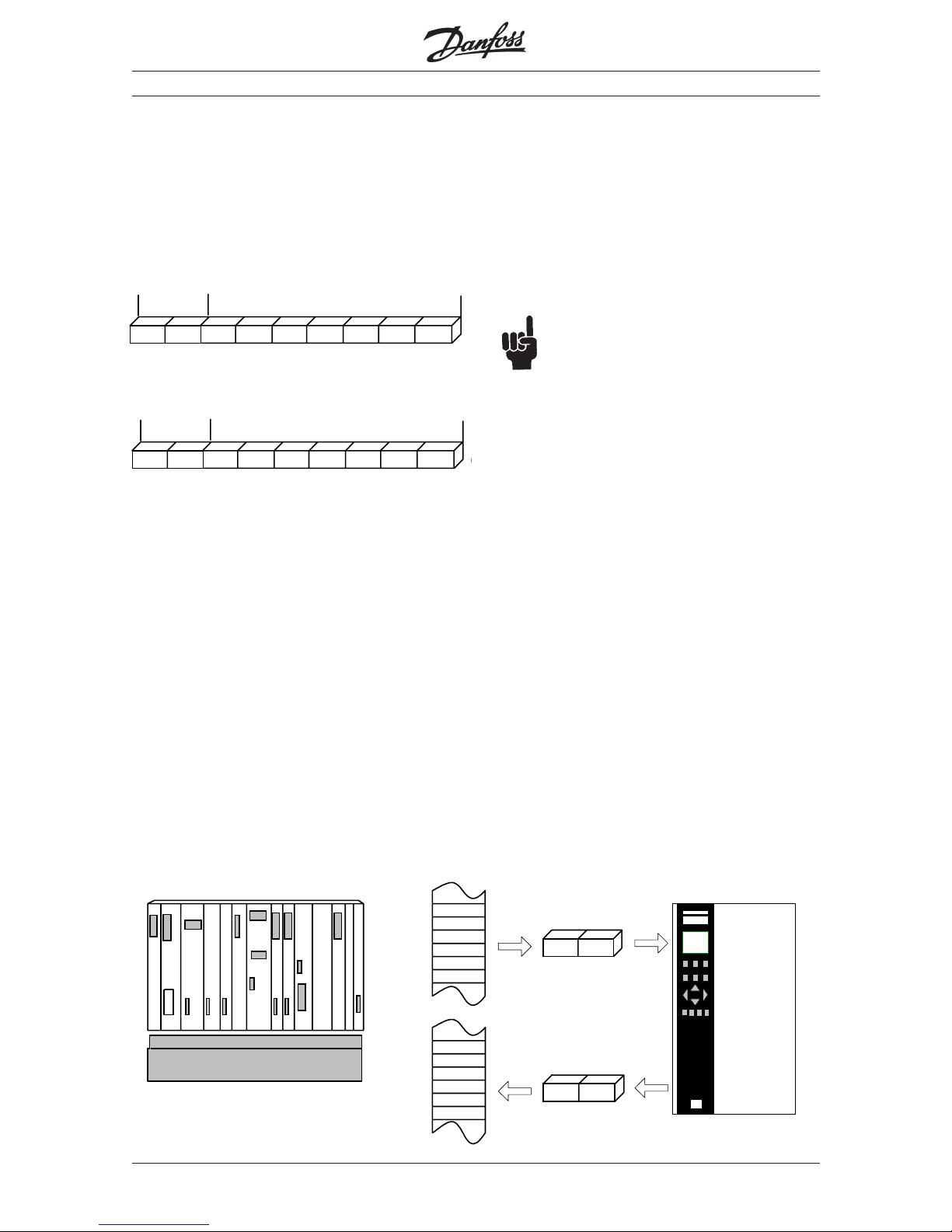
■ Process Data.
The VLT®5000 INTERBUS option, offers a flexible
way for the user to customize the number of
Process Data. The process Data of the VLT®5000
is split in two main parts: The first two words that is
reserved for the Drive profile and the user
definable Process data (PCD1 to PCD7).
Process Data
The first two words are fixed on the VLT®5000
option, whereas the input and output PCD1 to
PCD7 can be selected by the user. The number of
PCDs active in a system is user selectable from 0
(zero) up to 7 words. The number of PCDs is
always selected in pairs (input and output).
For the first 2 fixed words of Data, in the PQ and PI
Data, the Danfoss VLT®5000 offers two different
types of profiles: Drivecom and Danfoss. The
Drivecom profile fullfills the requirement of Drivecom
21, speed setting 1. The Drivecom and Danfoss
profiles will be explained in detail in chapter 7 & 8.
PCD1 to PCD7 can be used in a flexible way to read
and write the VLT®5000 parameters, or high speed
transfer of data to the Syncronizing and positioning
Card (Sync/Pos Card).
Changing the number of PCDs can be done by
accesing the VLT®5000s Parameter 807. The
Parameter can be changed at any time, but the
changes wil first take place at the next powerup, or if
the Master sends out a Bus reset command.
Please note that changing the number of
PCDs also may change the mapping of the
Masters I/O Area (PC/PLC).
The VLT®5000 INTERBUS option features the
disabling of PQ Data. PQ can be made inactive,
this means that the VLT®5000 ingnores the content
of all PQ Data, but the VLT®5000 continues to
update the PI Data. This feature is used during
reconfiguration of a running VLT®5000 system and
ensures that no parameter is changed by mistake.
The drawing below shows the default setting of a
system with no PCD words. The system only
consist of control word and main reference for the
PQ Data, and status word and main actual value
for the PI Data. In this system the Control word is
mapped into the PLCs output memory QW000
and the reference is mapped to the output memory
QW002. The status word of the VLT®5000 is
mapped into the input word IW000 of the PLC and
the feedback (main actual value) is mapped to
IW002.
Fixed
Fixed
User definable
User definable
PI
PQ
STW
MAV
STW MAV
MRVCTW
CTW
MRV
QW 000
QW 002
IW 000
IW 002
PLC VLT®5000INTERBUS
CTW MRV PCD1 PCD2 PCD3 PCD4 PCD5 PCD
STW MAV PCD1 PCD2 PCD3 PCD4 PCD5 PCD
6
Page 14

MG.10.O1.02 VLT is a registered Danfoss trademark
14
VLT® 5000 INTERBUS
■ Process Data, PCD.
To enable the use of PCD data, of the VLT®5000
INTERBUS option, the amount of PCD Datawords
has to be configured in Parameter 807, where as the
contents of each single PCD word has to be
configured in Parameter 915 and 916. This can be
done in two different ways: setting parameter 915
and 916, or by using the the INTERBUS object
6000
H
and 6001H.
After setting parameter 807 to match the desired
amount of PCD Data, the VLT®5000 needs to be
configured, for assigning Parameters to each single
PCD words. The VLT®5000 stores this information
in Parameter 915 and 916. The INTERBUS objects
6000
H
and 6001H are images of the two Parameters.
Changing Parameter 915/916 has immidiatly effect
on the PCD data.
The drawing below shows the relation between the
INTERBUS object 6000
H
/6001H and VLT®5000
Parameter 915/916.
The INTERBUS Object 6000
H
and 6001H is an Array of
words that has following structure:
The sub Index number 1 contains the number of
process data bytes. For each byte of process data
2 sub indexes are used. Sub index 2 contains the
Object number, sub index 3 is the index of the object,
if the object is of type array. The next two indexes are
for the next byte of process data. If a Object is of type
Word it uses 4 Sub indexes, wheras the three last Sub
indexes are not used, and must be set to zero.
The 6000
H
6001H Objects can have from 9 up to 37
Sub indexes depending on how many PCD words
there has been assigned. The drawing below shows a
configuration with 2 PCD words assign for reading
parameter 520 (Current) and parameter 528 (digital
input). For writing parameter 204 (minimum reference)
and parameter 221 (Torque limit) is used.
The output data to the VLT®5000 can be disabled by
Interbus Object 6002
H
. By setting the Interbus object
6002H to 00H all imcomming process data wil not be
transimitted to the VLT5000. Setting Interbus object
6002
H
to FFH reactivates the updating of output data.
After a power up the option always sets objects 6002
H
to FFH .
Writing to Interbus Object 6001
H
automaticly sets object 6002H to 00H an
thereby disables the inputs. The user has
to write 0FF
H
to Object 6002
H
manually.
Process Data
Bytes of PQ/PI Data
Description
Object number
Object number
Sub Index
Object number
Sub Index
Sub Index
Object number
Sub Index
Data type
Unsigned 8
Unsigned 8
Unsigned 16
Unsigned 16
Unsigned 16
Unsigned 8
Unsigned 8
Unsigned 16
Unsigned 8
Sub index
1
2
3
4
6
5
9
8
7
37 Unsigned 8
Sub Index
STW
MAV
PCD2
PCD1
CTW
MRV
PCD2
PCD1
6001
17
6040
00
0000
00
6042
00
0000
00
56BC
00
0000
00
56CD
00
0000
00
6000
17
6041
00
0000
00
6044
00
0000
00
57F8
00
0000
00
5900
00
0000
00
204
0
0
0
0
0
221
915 [1]
520
0
0
0
0
0
528
916
MRV PCD1
PCD2CTW
STW MAV PCD1
PCD2
915 [2]
{
PCD2
{
PCD1
{
MRV
{
CTW
{
STW
{
MAV
{
PCD1
{
PCD2
Interbus objects
VLT5000
Parameters
916 [1]
916 [2]
IW 000
IW 002
QW 002
QW 000
Page 15

VLT® 5000 INTERBUS
MG.10.O1.02 VLT is a registered Danfoss trademark
15
Drivecom State machine
The state machine describes the device status and
the possible control sequence of the drive. A status
represents a specific internal and external response.
By means of device control commands and/or
internal events, the status can be changed and a
control sequence thus executed. The current status
can be read out by way of the VLT®5000 status word.
In the flowchart to the right, this explanation may help
you understanding the
drawing: to change from
state A to state B, the condition Controlword bit 1
has to be set equal to 0. The coarses the
transition 0 to be exequted. In state B the
statusword is equal to xx01
H
.
Drivecom 21 Profile.
Not ready to switch on
STW = xx00h
Switched on
0
1
2
11
7
3
4 5
6
9
8
12
10
STW = xx33h
Disable Voltage
xxxx xx0x or
Qiuck stop
xxxx x01x
Shutdown
xxxx x110
Disable Voltage
xxxx xx0x
Switch on
xxxx x111
Stop
xxxx x110
Enable
operation
xxxx 1111
Disable
operation
xxxx x01x
Shutdown
xxxx x110
Qiuck stop
xxxx x01x
Disable voltage
xxxx xx0x
Disable voltage
xxxx xx0x or
Quick stop
xxxx x01x
Reset malfunction
0xxx xxxx
1xxx xxxx
↓
Operation enabled
STW = xx37h
Enabled Ramp
STW = xx37h
No Freeze
STW = xx37h
Start
STW = xx37h
Quick stop active
STW = xx17h
13
14
15
STW = xx38h
STW = xxxx xxxx x1xx 1xxx
JOG 1
STW = xx37h
Malfunction reaction
active
Malfunction
Ready to switch on
STW = xx31h
Switch on disabled
STW = xx40h
Power on
Drivecom 21
Danfoss specific
State B
STW = xx01h
0
State A
condition
xxxx xx0x
transition 0
Page 16

MG.10.O1.02 VLT is a registered Danfoss trademark
16
VLT® 5000 INTERBUS
Data transitions of the device control
The following describes each transaction that the
Drivecom statemachine follows, by a given
command.
0 Input of the state machine ➠ NOT READY TO
SWITCH ON
Event: - Reset
Action: - Start self test
- Start initialisation
1 NOT READY TO SWITCH ON ➠ SWITCH ON
DISABLED
Event: - Error-free self test
- Initialisation completed without errors occurring
Action: - Activate communication and process data
monitoring
2 SWITCH ON DISABLED ➠ READY TO SWITCH
ON
Event: - Shutdown command
Condition: - Depending on the manufacturer-specific
requirements (e.g. power section ready)
Action: - None
3 READY TO SWITCH ON ➠ SWITCHED ON
Event: - Switch-on command
Action: - The power section is switched on if it is not
already switched on.
4 SWITCHED ON ➠ OPERATION ENABLED
Event: - Enable-Operation command
Action: - Enable drive function
5 OPERATION ENABLED ➠ SWITCHED ON
Event: - Disable-Operation command
Action: - Execute the parameter-definable DriveDisable-Function
6 SWITCHED ON ➠ READY TO SWITCH ON
Event: - Shutdown command
Action: - The power section can be switched off
7 READY TO SWITCH ON ➠ SWITCH ON DISABLED
Event: - Quick-Stop or Disable-Voltage command
Action: - None
8 OPERATION ENABLED ➠ READY TO SWITCH
ON
Event: - Shutdown command
Action: - Execute the parameter definable DriveDisable-Function
- The power section can be switched off
9 OPERATION ENABLED ➠ SWITCH ON DISABLED
Event: - Disable-Voltage command
Action: - Disable drive function
- The power section can be switched off
10 SWITCHED ON ➠ SWITCH ON DISABLED
Event: - Disable-Voltage command
or
- Quick-Stop command
Action: - The power section can be switched off
11 OPERATION ENABLED ➠ QUICK STOP ACTIVE
Event: - Quick-Stop command
Action: - Trigger the parameter-definable QuickStop-Function
12 QUICK STOP ACTIVE ➠ SWITCH ON DISABLED
Event: - Quick stop has been completed
or
- Disable-Voltage command
Action: - Disable drive function
- The power section can be switched off
13 All states ➠ MALFUNCTION REACTION ACTIVE
Event: - Drive malfunction detected
Action: - Trigger malfunction reaction depending on
the fault
14 MALFUNCTION REACTION ACTIVE ➠ MALFUNCTION
Event: - Malfunction reaction concluded
Action: - Disable drive function
- The power section can be switched off
15 MALFUNCTION ➠ SWITCH ON DISABLED
Event: - Malfunction-Reset command
Condition: - Malfunction is no longer present
Action: - Malfunction reset is executed
Drivecom 21 Profile.
Page 17

VLT® 5000 INTERBUS
MG.10.O1.02 VLT is a registered Danfoss trademark
17
Control word as per Drivecom 21 Standard
(parameter 512 = Drivecom)
Master➝Slave
15 14 13 12 11 10 9 8 7 6 5 4 3 2 1 0 Bit
no.
Bit Bit = 0 Bit =1
00 Switch off Switch on
01 Disable voltage Enable voltage
02 Quick stop Run
03 Disable operation Enable operation
04 Disable Ramp Enable Ramp
05 Freeze Run enable
06 Ramp stop Start
07 No function Reset
08 Drivecom reserved
09 Drivecom reserved
10 Drivecom reserved
11 Jog 1 OFF Jog 1 ON
12 Danfoss reserved
13 Choice of Setup 1 (lsb)
14 Choice of Setup 2 (msb)
15 Forward Reversing
Bit 00, Switch OFF/ON:
Bit 00= "0" execute transition 2, 6 or 8
Bit 00 = "1" execute transition 3
Bit 01, Disable/Enable Voltage:
Bit 01= "0" execute transition 9, 10 or 12
Bit 01 = "1" = Enable Voltage
Bit 02, Quick stop/Run:
Bit 02= "0" execute transition 7, 10 or 11.
Bit 02 = "1" = Quick stop not active.
Bit 03, Disable/enable Operation:
Bit 03= "0" execute transition 5.
Bit 03 = "1" = Enable operation
Bit 04, Quick-stop/ramp:
Bit 04= "0" execute transition 7 or 11, Quick stop
Bit 04 = "1" = Enable ramp.
Bit 05, Freeze output frequency/ramp enable:
Bit 05 = "0" means that the given output frequency is
maintained even if the reference is changed.
Bit 05 = "1" means that the frequency converter is
again able to regulate, and the given reference is
followed.
Bit 06, Ramp stop/start:
Bit06= "0" The VLT controls the motor down to
stop.
Bit 01 = "1" = Start command to the VLT is given
Bit 07, No function/reset
Reset of trip. Bit 07 = "0" means that there is no
reset. Bit 07 = "1" means that a trip is reset.
Bit 08, 09 and 10 :
Drivecom reserved.
Bit 11, Jog 1 OFF/ON:
Activation of pre-programmed speed in
parameter 509 (Bus JOG 1). JOG 1 is only
possible when Bit 04 = "0" and bit 00-03 = "1".
Bit 12,:
Danfoss reserved.
Bits 13/14, Choice of Setup:
Bits 13 and 14 are used for choosing among the
four menu Setups in accordance with the
following table:
Setup Bit 14 Bit 13
10 0
20 1
31 0
41 1
Bit 15, No function/reversing:
Reversing of the direction of rotation of the motor.
Bit 15 = "0" leads to no reversing, bit 15 = "1"
leads to reversing.
Please note that, in the factory setting, reversing
has been chosen as digital in parameter 506,
which means that bit 15 will only lead to reversing
if bus, logic or or logic and (however, logic and
only together with terminal 19) has been
selected.
NB!
Unless otherwise mentioned, the control
word bit is combined (gated) with the
corresponding function on the digital
inputs as a logical "or" function.
Drivecom 21 Profile.
Control
word
Bus
reference
Page 18

MG.10.O1.02 VLT is a registered Danfoss trademark
18
VLT® 5000 INTERBUS
Status word (according to Drivecom standard)
The status word is used for informing the master
(e.g. a PC) of the condition of the VLT 5000.
Slave➝Master
15 14 13 12 11 10 9 8 7 6 5 4 3 2 1 0 Bit
no.
Bit Bit = 0 Bit =1
00 Not ready to Ready to
switch on switch on
01 Switched off Switched on
02 Operation disabled Operatin enabled
03 No malfunction Malfunction
04 Voltage disabled Voltage Enable
05 Quick stop Run
06 Switch on disable Switch on
enable
07 No warning Warning
08 Danfoss reserved
09 Remote disabled Remote enabled
10 Setpoint not reached Setpoint reached
11 Speed limit Speed limit
not active active
12 Drivecom reserved
13 Drivecom reserved
14 Not running Running
15 Danfoss reserved
Bit 00, Not ready to switch on/Ready to switch on:
Bit 00 = "0" state less than ´´Ready to switch on
Bit 00 = "1" state at least = ´´Ready to Switch on
Bit 01, Switch off/Switch on:
Bit 00 = "0" state less than ´´Switched on
Bit 00 = "1" state at least = ´´Switched on
Bit 02, Operation disable/Operation enable:
Bit 00 = "0" state less than ´´Operation enable
Bit 00 = "1" state at least = ´´Operation enable
Bit 03, No fault/trip:
Bit 03 = "0" means that VLT 5000 Series is not in a
fault condition. Bit 03 = "1" means that VLT 5000
Series has tripped and needs a reset signal in order
to run.
Bit 04, Voltage disable/Voltage enable:
Output
frequency
Status
word
Bit 04 = "0" means that control word bit 01 = "1".
Bit 04 = "1" means that control word bit 01 = "0".
Bit 05, Quick stop/Run:
Bit 05 = "0" means that control word bit 02 = "1".
Bit 05 = "1" means that control word bit 02 = "0".
Bit 06, Start enable/start disable:
Bit 06 = "0" state not ´´Switch on disable
Bit 06 = "1" state = ´´Switch on enable
Bit 07, No warning/warning:
Bit 07 = "0" means that there is no unusual
situation. Bit 07 = "1" means that an abnormal
condition has arisen for the VLT 5000 Series. All
warnings are described in the Operating
Instructions.
Bit 08, Danfoss reserved:
Bit 09, Remote disable/ Remote enable:
Bit 09 = "0" means that VLT 5000 Series has been
stopped by means of the stop key on the control
panel, or that Local operation has been selected in
parameter 002. Bit 09 = "1" means that it is
possible to control the frequency converter via the
serial port.
Bit 10, Setpoint not reached/Setpoint reached:
Bit 10 = "0" means that the actual motor speed is
different from the speed reference set. This can be
the case i.a. while the speed is ramped up/down
during start/stop. Bit 10 = "1" means that the
present motor speed equals the speed reference
set.
Bit 11, Speed limit not active/speed limit active:
Bit 11 = "0" means that the output frequency is out
of the range set in parameter 225 (Warning: Low
frequency) and parameter 226 (Warning: High
frequency). Bit 11 = "1" means that the output
frequency lies within the mentioned range.
Bit 12, Drivecom reserved
Bit 13, Drivecom reserved
Bit 14, Running/Not running:
Bit 14 = "0" means that the motor is not running.
Bit 14 = "1" means that VLT 5000 Series has a start
signal or that the output frequency is greater than 0
Hz.
Bit 15, Danfoss reserved.
Drivecom 21 Profile.
Page 19

VLT® 5000 INTERBUS
MG.10.O1.02 VLT is a registered Danfoss trademark
19
Bus reference value (Drivecom Profile):
Master➝Slave
1514131211109876543210Bit no.
The bus reference value is transmitted to the frequency
converter in the form of a 16-bit word. The value is
transmitted as a whole number (-32768 to 32767). The
value is handled as RPM.
Actual output RPM
Slave➝Master
1514131211109876543210Bit no.
The value of the actual output RPM of the Motor, is
transmitted in the form of a 16-bit word. The value is
transmitted as a whole number (-32768 to 32767).
Drivecom 21 Profile.
Status
word
Output
frequency
Control
word
Bus
reference
Page 20

MG.10.O1.02 VLT is a registered Danfoss trademark
20
VLT® 5000 INTERBUS
■ Drivecom 21 objects.
The VLT®5000 supports 9 Drivecom specific objects.
The objects can be access by PCP communication.
4 of these objects can also be accessed as process
data.
Object 6040H, Control Word:
This object is the same as the Drivecom Control Word
Object 6041H, Status Word:
This object is the same as the Drivecom status word .
Object 6042H, Nominal-Speed-Value :
This object is the same as the Bus reference (MRV).
Object 6043H, Reference-Speed-Variable:
This is the reference after the Ramp. This value is read
only (-32768 to 32767) .
Object 6044H, Actual-Speed-Value:
This object is the same as the Actual output RPM.
The value of the actual output RPM of the Motor, is
transmitted in the form of a 16-bit word. The value is
transmitted as a whole number (-32768 to 32767).
Object 6046H, Speed-min-max-amount:
The Speed-Min-Max-Amount Object is composed of
the Speed-Min-Amount and Speed-Max-Amount sub
objects. These subobjects have no unit and have values within a range from 0 to 4 294 967 295 (unsigned
32).The Interbus Option translates these two indexes
into the VLT®5000 parameter 204 and 205. Based on
Parameter 106 (Motor Norminal Speed) the option
calculation new values for P.204 & P.205.
Object 6048H, Speed-Acceleration:
The Speed-Acceleration object specifies the slope of
the acceleration ramp (α) The object has 2 indexes
where: Index 1, is the Delta-Speed (unsigned 32) and
index 2 is Delta-Time (unsigned 16). If Delta-Time is
set to 0 (zero) the ramp is disabled. The VLT®5000
Interbus Option translate these two values into the
VLT®5000 parameters 106, Motor norminal speed
and parameter 207, ramp up time.
Object 6049H, Speed-Deceleration:
The Speed-deceleration object specifies the slope of
the deceleration ramp (α) The object has 2 indexes
where: Index 1, is the Delta-Speed (unsigned 32) and
index 2 is Delta-Time (unsigned 16). If Delta-Time is
set to 0 (zero) the ramp is disabled. The VLT®5000
Interbus Option translate these two values into the
VLT®5000 parameters 106, Motor norminal speed
and parameter 208, ramp down time.
T, time
N, Rpm
∆∆
∆∆
∆n
∆∆
∆∆
∆t
αα
αα
α
T, time
N, Rpm
∆∆
∆∆
∆n
∆∆
∆∆
∆t
αα
αα
α
The VLT®5000 will first activate the
changes when both indexes are written.
Since the VLT®5000 translates the two
indexes into VLT®5000 paramters, the
value written to Object 6048
H
may be dif-
ferent from a following read, but the slope
(α) is correct !
The VLT®5000 will first activate the changes
when both indexes are written. Since the
VLT®5000 translates the two indexes into
VLT®5000 paramters, the value written to
Object 6049
H
may be different from a follow-
ing read, but the slope (α) is correct !
Object 603FH, Malfunction:
This is the errors reported back to the Master system.
A detailed list is on the next page.
Object 6052H, Normial-Percentage :
This object is the Normial setpoint in %. . The value is
transmitted as a whole number ±100% = ±4000
H.
This value is read only.
Object 6054H, Actual-Percentage :
This object is the actual speed of the motor . The
value is transmitted as a whole number ±100% =
±4000
H
Drivecom 21 Objects
Page 21

VLT® 5000 INTERBUS
MG.10.O1.02 VLT is a registered Danfoss trademark
21
Meaning VLT-Code Drivecom Drivecom
Alarmword Malfunc. Malfunc group
(Hex) Code
No alarm 0000 0000 0 No malfunction
Brake test Failed 0000 0001 7110 brake chopper
Trip locked 0000 0002 1000 general malfunction
Auto-optimisation not OK 0000 0004 5210 measurement circuit
Auto-optimisation OK 0000 0008 0 no error
Power-up fault 0000 0010 1000 general malfunction
ASIC fault 0000 0020 5200 hardware control fault
HPFB bus timeout 0000 0040 8100 monitoring communication
Standard bus timeout 0000 0080 8100 monitoring communication
Short circuiting 0000 0100 2130 short circuit
Switch mode fault 0000 0200 5115 U5 supply
Earth fault 0000 0400 2240 earth leakage
Overcurrent 0000 0800 2310 continuous over-current
Torque limit 0000 1000 8311 excess torque
Motor thermistor 0000 2000 4310 excess temperature drive
Motor overloaded 0000 4000 2312 continuous over-current 2
Inverter overloaded 0000 8000 2316 continuous over-current 1
DC Link undervoltage 0001 0000 3220 internal under-voltage
DC Link overvoltage 0002 0000 3210 internal over-voltage
Phase fault 0004 0000 3130 phase failure
Live zero fault 0008 0000 7300 sensor
Heat sink temperature too high 0010 0000 4210 excess temperature device
Motor phase U missing 0020 0000 3131 phase failure L1
Motor phase V missing 0040 0000 3132 phase failure L2
Motor phase W missing 0080 0000 3133 phase failure L3
Quick discharge not OK 0100 0000 9000 External malfunction
Interbus Error codes:
Interbus Error Codes
Page 22

MG.10.O1.02 VLT is a registered Danfoss trademark
22
VLT® 5000 INTERBUS
■ PCP Communication.
For acyclical read and writting of VLT®5000
parameters and Interbus Objects, the PCP-Channel
has to be used. The Danfoss VLT®5000 option
supports following services:
Initiate
Establish connection between master and
VLT®5000
Abort
Cancel Connection between Master and VLT®5000
Read
Read VLT®5000 Parameter or Interbus Objects.
Write
Write VLT®5000 Parameter or Interbus Objects.
Get OD, both short and long are supported
Get Object dictionary from VLT®5000.
and
Identify
Identification of the VLT®5000 to the Master.
Following entries has to be done in the Master for
PCP communication:
All parameters in the VLT®5000 are mapped to the
Danfoss specific objects starting from object 22000
D
=
55F0
H
. The first object is 22001D, which corresponds
to read VLT®5000 parameter 001, language. 22002
D
corresponds to VLT®5000 parameter 2 and so on.
This means that all VLT®5000 parameters simply can
be accessed by using PCP communication, just
adding 22000
D
to the VLT®5000 parameter.
To access the VLT®5000 objects for reading and
writing, it is necesarry to set up the correct data size
and index for the parameter. The option board can
provide the complete list of objects to the user by
using the GET OD command. Alternally the user can
set up the command for the object manualy.
Communication referens
Transmitt buffer lengh
Receive buffer lengh
Supported Service request
Supported Service response
2
246
246
80 30 00
H
00 00 00
H
Page 23

VLT® 5000 INTERBUS
MG.10.O1.02 VLT is a registered Danfoss trademark
23
Control word under VLT standard (parameter 512 =
FC Drive)
The control word is used for sending commands
from a master (e.g. a PC) to a slave (VLT 5000
Series).
Master➝Slave
1514131211109876543210Bit
no.
Bit Bit = 0 Bit = 1
00 Preset reference choice lsb
01 Preset reference choice msb
02 DC brake Ramp
03 Coasting Enable
04 Quick-stop Ramp
05 Hold Ramp
enable
06 Ramp stop Start
07 No function Reset
08 No function Jog
09 Ramp 1 Ramp 2
10 Data not valid Valid
11 No function Relay 01
activated
12 No function Relay 04
activated
13 Choice of Setup lsb
14 Choice of Setup msb
15 No function Reversing
Bit 00/01:
Bits 00 and 01 are used for choosing among the
four pre-programmed references (parameters 215-
218) in accordance with the following table:
Preset ref. Parameter Bit 01 Bit 00
1 215 0 0
2 216 0 1
3 217 1 0
4 218 1 1
NB!
Parameter 508 is where to choose the
way bits 1/12 are to be combined (gated)
with the corresponding function on the
digital inputs.
Bit 02, DC BRAKE:
Bit 02 = "0" leads to DC braking and stop. Braking
current and duration are set in parameters 125 and
126. Bit 02 = "1" leads to ramping.
Bit 03, Coasting/enable:
Coasting stop. Bit 03 = "0" leads to a stop. Bit 03 =
"1" means that the frequency converter is able to
stop, provided the other conditions for starting are
fullfilled. Note: In parameter 502 the choice is made
as to how bit 03 is to be combined (gated) with the
corresponding function in the digital inputs.
Bit 04, Quick-stop/ramp:
Quick-stop which uses the ramp time in parameter
212. Bit 04 = "0" leads to a quick-stop. Bit 04 = "1"
means that the frequency converter is able to start,
provided the other conditions for starting are fulfilled.
Note: In parameter 503 the choice is made as to
how bit 04 is to be combined (gated) with the
corresponding function on the digital inputs.
Bit 05, Freeze output frequency/ramp enable:
Bit 05 = "0" means that the given output frequency is
maintained even if the reference is changed.
Bit 05 = "1" means that the frequency
converter is again able to regulate, and the
given reference is followed.
Bit 06, Ramp stop/start:
An ordinary ramp stop that uses the ramp time in
parameters 207/208 or 209/210; in addition, output
relay 01 or 04 will be activated when the output
frequency is 0 Hz, provided Relay 123 has been
selected in parameter 323 or 326. Bit 06 = "0" leads
to a stop. Bit 06 = "1" means that the frequency
converter is able to start, provided the other
conditions for starting are fulfilled. Note: In
parameter 505 the choice is made as to how bit 06
is to be combined (gated) with the corresponding
function on the digital inputs.
Bit 07, No function/reset
Reset of trip. Bit 07 = "0" means that there is no
reset. Bit 07 = "1" means that a trip is reset.
Bit 08, Activation of Jog speed in parameter 213:
Bit 08 = "0": Jog speed not activated. Bit 08 = "1"
means that the motor is running at Jog speed.
Bit 09, Choice of ramp 1/2:
Bit 09 = "0" means that ramp 1 is active
(parameters 207/208). Bit 09 = "1" means that
ramp 2 (parameters 209/210) is active.
Bus
reference
Control
word
FC Profile
Page 24

MG.10.O1.02 VLT is a registered Danfoss trademark
24
VLT® 5000 INTERBUS
Status word under VLT standard
The status word is used for informing the master
(e.g. a PC) about the condition of the slave (VLT
5000 Series).
Slave➝Master
15 14 13 12 11 10 9 8 7 6 5 4 3 2 1 0 Bit
no.
Bit Bit = 0 Bit = 1
00 Control not ready Ready
01 VLT not ready Ready
02 Coasting Enable
03 No fault Trip
04 Reserved
05 Reserved
06 Reserved
07 No warning Warning
08 Speed ≠ ref. Speed = ref.
09 Local control Bus control
10 Out of range Frequency OK
11 Not running Running
12 VLT OK Stalling, autostart
13 Voltage OK Above limit
14 Torque OK Above limit
15 Timer OK Above limit
Bit 00, Control not ready/ready:
Bit 00 = "0" means that the frequency converter
has tripped.
Bit 00 = "1" means that the frequency converter
controls are ready, but that the power component is
not necessarily receiving any power supply (in case
of external 24 V supply to controls).
Bit 01, VLT not ready/ready:
Same meaning as bit 00; however, there is also a
supply to the mains component, and the frequency
converter is ready to run when it receives the
necessary start signals.
Bit 02, Coasting/enable:
Bit 02 = "0" means that the control word bit 03 is
"0" (Coasting) or that VLT 5000 Series has tripped.
Bit 02 = "1" means that control word bit 03 is "1"
and that VLT 5000 Series has not tripped.
Bit 03, No fault/trip:
Bit 03 = "0" means that VLT 5000 Series is not in a
fault condition. Bit 03 = "1" means that the VLT
Output
frequency
Status
word
Bit 10, Data not valid/valid:
Used for telling VLT 5000 whether the control word is
to be used or ignored. Bit 10 = "0" means that the
control word is ignored. Bit 10 = "1" means that the
control word is used. This function is relevant because
the control word is always contained in the telegram,
regardless of the type of telegram used, i.e. it is
possible to disconnect the control word if it is not to be
used in connection with updating or reading of
parameters.
Bit 11, Relay 01:
Bit 11 = "0": Relay 01 not activated. Bit 11 = 1:
Relay 01 activated, provided Control word bit has
been chosen in parameter 323.
Bit 12, Relay 04:
Bit 12 = "0": Relay 04 has not been activated. Bit
12 = "1": Relay 04 has been activated, provided
Control word bit has been chosen in parameter 326.
NB!
Unless otherwise mentioned, the control
word bit is combined (gated) with the
corresponding function on the digital inputs
as a logic "or" function.
Bits 13/14, Choice of Setup:
Bits 13 and 14 are used for choosing among the
four menu Setups in accordance with the following
table:
Setup Bit 14 Bit 13
10 0
20 1
31 0
41 1
This function is only possible if Multi-Setup has been
selected in parameter 004.
NB!
Parameter 507 is used for choosing how bits 13/14
are to be combined (gated) with the corresponding
function on the digital inputs.
Bit 15, No function/reversing:
Reversing of the direction of rotation of the motor.
Bit 15 = "0" leads to no reversing, bit 15 = "1" leads
to reversing.
Please note that, in the factory setting, reversing
has been chosen as digital in parameter 506, which
means that bit 15 will only lead to reversing if bus,
logic or or logic and (however, logic and only
together with terminal 19) has been selected.
FC Profile
Page 25

VLT® 5000 INTERBUS
MG.10.O1.02 VLT is a registered Danfoss trademark
25
5000 Series has tripped and needs a reset signal in
order to run.
Bit 04, Reserved.
Bit 05, Reserved.
Bit 06, Reserved.
Bit 07, No warning/warning:
Bit 07 = "0" means that there is no unusual
situation. Bit 07 = "1" means that an abnormal
condition has arisen for the VLT 5000 Series. All
warnings are described in the Operating
Instructions.
Bit 08, Speed ≠ ref/speed = ref.:
Bit 08 = "0" means that the actual motor speed is
different from the speed reference set. This can be
the case i.g. while the speed is ramped up/down
during start/stop. Bit 08 = "1" means that the
present motor speed equals the speed reference
set.
Bit 09, Local control/Bus control:
Bit 09 = "0" means that VLT 5000 Series has been
stopped by means of the stop key on the control
panel, or that Local operation has been selected in
parameter 002. Bit 09 = "1" means that it is
possible to control the frequency converter via the
serial port.
Bit 10, Out of operating range/Frequency limit OK:
Bit 10 = "0" means that the output frequency is out
of the range set in parameter 225 (Warning: Low
frequency) and parameter 226 (Warning: High
frequency). Bit 10 = "1" means that the output
frequency lies within the mentioned range.
Bit 11, Does not run/running:
Bit 11 = "0" means that the motor is not running.
Bit 11 = "1" means that VLT 5000 Series has a start
signal or that the output frequency is greater than 0
Hz.
Bit 12, VLT OK/stalling, autostart:
Bit 12 = "0" means that there is no temporary overtemperature on the inverter. Bit 12 = "1" means
that the inverter has stopped because of overtemperature, but that the unit has not tripped and
will continue, once the overtemperature stops.
Bit 13, Voltage OK/above limit:
Bit 13 = "0" means that the voltage limits of VLT
5000 Series have not been exceeded. Bit 13 = "1"
means that the DC voltage of the VLT 5000 Series
intermediate circuit is too low or too high.
Bit 14, Torque OK/above limit:
Bit 14 = "0" means that the motor current is lower
than the torque limit selected in parameter 221. Bit
14 = "1" means that the torque limit in parameter
221 has been exceeded.
Bit 15, Timers OK/above limit:
Bit 15 = "0" means that the timers for motor
thermal protection (described on page 67) and VLT
thermal protection, respectively, have not exceeded
100%. Bit 15 = "1" means that one of the timers
has exceeded 100%.
Bus reference value (FC Profile):
Master➝Slave
1514131211109876543210Bit no.
The frequency reference value is transmitted to the
frequency converter in the form of a 16-bit word.
The value is transmitted as a whole number (0-
32767). 16384 (4000 Hex) corresponds to 100%.
(Negative figures are formed by means of 2's
complement.)
The bus reference has the following format:
Parameter 203 = "0"
"ref
MIN
-ref
MAX
"
0-16384 (4000 Hex) ~ 0-100% ~ ref
MIN
- ref
MAX
Parameter 203 = "1"
-ref
MAX
- +ref
MAX
-16384 (C000 Hex) - +16384 (4000 Hex) ~
-100- +100% ~ -ref
MAX
- +ref
MAX
Actual output frequency
Slave➝Master
15 14 13 12 11 10 9 8 7 6 5 4 3 2 1 0 Bit no.
The value of the actual output frequency of the
frequency converter is transmitted in the form of a
16-bit word. The value is transmitted as a whole
number (0-32767). 16384 (4000 Hex) corresponds
to 100%. (Negative figures are formed by means of
2's complement).
Status
word
Output
frequency
Control
word
Bus
reference
FC Profile
Page 26

MG.10.O1.02 VLT is a registered Danfoss trademark
26
VLT® 5000 INTERBUS
Parameters
■ INTERBUS specific VLT parameters
Only the INTERBUS specific parameters (800 - 807
and 915, 916, 9 . . ) are described in this manual.
Most VLT 5000 Series parameters and their
functions are unaffected by the INTERBUS option.
Refer to the parameter description in the VLT 5000
Series product manual.
Special attention must be given to the following
parameters that are not described in this manual:
- 002: If operation site = Local, then control via
INTERBUS is not possible
- 100: If parameter 512 is set to DRIVECOM, it is
only possible to select speed open
loop or speed closed loop.
- 502 - 508: Selection of how to gate INTERBUS
control commands with control card
digital inputs.
- 512: Control word profile, selects a control word
according to DRIVECOM or a
Danfoss specified control word.
- 515 - 540: Data readout parameters that can be
used to read various actual data from
the VLT, for example actual status of
the analog and digital inputs of the
control card thus using these as
inputs to the master.
801 Baud rate select (BAUD RATE SELECT)
Selection:
✭ 500 kBaud (500 KBAUD) [30]
Function:
Selection of the INTERBUS transmission speed.
Description of selections:
- 500 kBaud: The INTERBUS transmission speed
is fixed to 500 kBaud at this time.
803 Bus time out (BUS TIME OUT)
Selection:
1 - 99 sec ✭ 1 sec
804 Bus time out function (TIME OUT FUNCT.)
Selection:
✭ Off (OFF) [0]
Freeze output frequency (FREEZE OUTPUT) [1]
Stop with auto restart (STOP) [2]
Output frequency = JOG freq. (JOGGING) [3]
Output freq. = Max. freq. (MAX SPEED) [4]
Stop with trip (STOP AND TRIP) [5]
Control without INTERBUS [6]
(NO COM OPT CONTROL)
Select setup 4 (SELECT SETUP 4) [7]
Function:
The time out counter is triggered at the first reception
of a valid control word. When process data is used.
Acyclical PCP will not trigger the time out counter.
The time out function will be activated if CTW is not
updated within the specified time, set in parameter
803.
The VLT remains in the time out state until one of the
following four conditions is true:
1. Valid control word is received
and reset (Bus,
terminals or local control panel) is activated (reset
is only necessary when the time out function
Stop w. trip is selected) ⇒ control via INTERBUS
is resumed with the actual control word.
2. Parameter 002 = Local ⇒ Local control via local
control panel is enabled.
3. Parameter 928 = Disabled ⇒ Normal control via
terminals and RS485 is enabled.
The time out counter is reset and must be
trigged by a valid control word before a new time
out can be activated.
4. Parameter 804 = Off ⇒ control via INTERBUS is
resumed and the most recent control word is
used.
Description of selections:
- Freeze output frequency: Freeze output
frequency until communication is resumed.
- Stop with auto restart: Stop with auto restart
when communication is resumed.
- Output frequency = JOG freq.: Motor will run at
JOG frequency until communication is resumed.
- Output frequency = Max. freq.: Motor will run at
max. frequency until communication is resumed.
- Stop with trip: Motor is stopped, reset needed for
restart, see explanation above.
- Control without INTERBUS: Control via
INTERBUS is disabled and control is only possible
via standard RS485 interface, until communication
is resumed.
- Select setup 4: Setup 4 is selected if timeout
occurs. If communication is resumed the VLT will
not cange back to the setup it used before the
timeout occured.
Page 27

VLT® 5000 INTERBUS
MG.10.O1.02 VLT is a registered Danfoss trademark
27
Description of selections:
807 PCD size select (PCD SIZE SELECT)
Selection:
✭ 0 Word (0 WORDS) [0]
1 Word (1 WORDS) [1]
2 Word (2 WORDS) [2]
3 Word (3 WORDS) [3]
4 Word (4 WORDS) [4]
5 Word (5 WORDS) [5]
6 Word (6 WORDS) [6]
7 Word (7 WORDS) [7]
Function:
The PCD size select assigns the number of Process
data words, the VLT is using.
Change of parameter 807 is first executed at next
power up, or alarmstop from the INTERBUS Master.
915 PCD config. write (PCD IN WR-)
Selections:
Sub index 1 ([1] 000) Parameter #
Sub index 2 ([2] 000) Parameter #
Sub index 3 ([3] 000) Parameter #
Sub index 4 ([4] 000) Parameter #
Sub index 5 ([5] 000) Parameter #
Sub index 6 ([6] 000) Parameter #
Sub index 7 ([7] 000) Parameter #
Sub index 8 ([8] 000) Parameter #
Function:
Different parameters can be assigned to PCD 1-7 of
the PA data (the number of PCDs depends on the
setting in parameter 807). The values in PCD 1-7 will
be written to the selected parameters as
data values.
Description of selections:
The order of the subindexes corresponds to the order
of the PCDs in the PQ + 2, i.e. subindex 1 ≈ PCD 3,
subindex 2 ≈ PCD 3 and so on. Each subindex can
hold the number of any of the VLT parameters.
Parameters
916 PCD config. read(PCD IN RD-)
Selections:
Sub index 1 ([1] 000) Parameter #
Sub index 2 ([2] 000) Parameter #
Sub index 3 ([3] 000) Parameter #
Sub index 4 ([4] 000) Parameter #
Sub index 5 ([5] 000) Parameter #
Sub index 6 ([6] 000) Parameter #
Sub index 7 ([7] 000) Parameter #
Sub index 8 ([8] 000) Parameter #
Function:
Different parameters can be assigned to PCD 1-7 of
the PPOs (the number of PCDs depends on the
PPO type). PCD 1-7 will hold the actual data value of
the selected parameters.
Description of selections:
The order of the subindexes corresponds to the order
of the PCDs in the PI + 2, i.e. subindex 1 ≈ PCD 3,
subindex 2 ≈ PCD 3 and so on. Each subindex can
hold the number of any of the VLT parameters.
927 Parameter edit
Selections:
Disabled [0]
✭ Enabled [1]
Function:
Editing parameters is possible via either INTERBUS
or the standard RS485 interface, but not both at the
same time. Parameter read is always possible via
the local control panel.
Description of selections:
- Disabled: Parameter edit via INTERBUS is
disabled. Parameter edit via standard RS485 is
possible.
- Enabled: Parameter edit via INTERBUS is
enabled. Parameter edit via standard RS485 port
is blocked
Page 28

MG.10.O1.02 VLT is a registered Danfoss trademark
28
VLT® 5000 INTERBUS
Parameters
928 Process control
Selections:
Disabled [0]
✭ Enabled [1]
Function:
Process control (setting of control word and speed
reference) is possible via either INTERBUS or the
standard RS485 interface, but not both at the same
time. Local control is always possible via the local
control panel. Control via control card terminals is
possible with either bus depending on the setting of
parameters 502-508.
Description of selections:
- Disabled: Process control via INTERBUS is
disabled. Process control via standard RS485 is
possible.
- Enabled: Process control via INTERBUS is
enabled. Process control via standard RS485 is
blocked.
The motor may start without notice when
parameter 928 is changed and start commands are
present.
953 Warning parameter 1 (WARN. PARA)
Selections:
Read only
No LCP access
Function:
A 16 bit bitstring where each bit is associated with a
specific warning according to the list below.
Bit = 0 when: Bit = 1 when:
0 Bus active Bus not Active
1 Not used
2 Not used
3 Not used
4 Actual value updated Actual value not
updated
5 Not used
6 Not used
7 No init error Init error
8 Remote bus OK Remote bus
disable
9 Not used
10 Not used
11 Not used
12 Internal SW error LSB
13 Internal SW error
14 Internal SW error
15 Internal SW error MSB
Bit 12-15 describes the Internal option error code.
971 Store data values (STORE DATA VALUE)
Selections:
✭ No action (NO ACTION) [0]
Store active setup (STORE ACTIVE SETUP) [1]
Store all setups (STORE ALL SETUPS) [2]
Store edit setup (STORE EDIT SETUP) [3]
Function:
Parameter values changed via INTERBUS are only
stored in RAM meaning that the changes are lost at
power down. This parameter is used to activate a
function that stores all parameter values in the
EEPROM thus retaining changed parameter values at
power down.
Description of selections:
No action: The store function is inactive.
Store active setup: All parameter values in the
active setup will be stored in the EEPROM. The
value returns to No action when all parameter
values have been stored.
Store all setups: All parameter values will be stored
in the EEPROM. The value returns to No action
when all parameter values have been stored.
Store edit setup: All parameter values in the setup
you are editing will be stored in the EEPROM. The
value returns to No action when all parameter
values have been stored.
980-982 Defined parameters (DEFINED PNU'S)
Selections:
Read only
Function:
These three parameters hold a list of all the
parameters that are defined in the VLT. Each of the
three parameters can be read as an array by means of
the PCP read service. It is also possible to read single
elements of the list by PCP Communication, by using
the corresponding subindex. The subindexes start at
1 and follow the order of the parameter numbers.
Page 29

VLT® 5000 INTERBUS
MG.10.O1.02 VLT is a registered Danfoss trademark
29
Parameters
-
Each parameter holds up to 116 elements (parameter
numbers). The number of parameters (980, 981 and
982) in use depends on the actual VLT configuration.
When a 0 is returned as parameter number the list
ends.
990-992 Modified parameters
(MODIFIED PNU'S)
Selections:
Read only
Function:
The three parameters holds a list of all the VLT
parameters that have been changed from factory
setting. Each of the three parameters can be read
as an array by means of the acyclical PCP read
service. The subindexes start at 1 and follow the order
of the parameter numbers. Each parameter hold up to
116 elements (parameter numbers). The number of
parameters (990, 991 and 992) in use depends on
how many parameters have been changed from
factory setting.
Read only parameters, as for example data read out
parameters, will not be registered as modified
eventhough they are changing.
When a 0 is returned as parameter number the list
ends.
Page 30

MG.10.O1.02 VLT is a registered Danfoss trademark
30
VLT® 5000 INTERBUS
■■
■■
■ VLT response time
The update time via the INTERBUS connection can
be divided in two parts:
1) The communication time, which is the time it
takes to transmit data from the master to the slave
(VLT 5000 with INTERBUS option), and 2) the
internal update time, which is the time it takes to
transmit data between the VLT 5000 control card
and the INTERBUS option card.
Communication time (t
com
) depends on the type of
master in use, the total number of bytes transmitet to
all slaves and the total length of the INTERBUS Cable.
The internal update time (t
int
) depends on the type of
data in question as there are different channels for
the data transfer where time critical data e.g.
control word has highest priority. The internal update
time for the different types of data are stated below.
Update
Data time, t
int
Control word/Main reference 2 msec
Status word/Actual speed 2 msec
Parameter read via PCD-part 2 msec
Parameter write via PCD1-2 83 msec
Parameter write via PCD3-4 165 msec
Parameter write via PCD5-7 325 msec
Parameter read via PCP XXY msec
Parameter write via PCP YYX msec
Timing
■■
■■
■ System update time
The system update time is the time it takes to
update all the slaves in the network when using
cyclical communication.
Actual master station delay:
- The information must be supplied by the
manufacturer of the actual INTERBUS master.
Example:
- INTERBUS G4 master using 4 words of
Process Data and 1 Word of PCP Data to 12
Slaves on the INTERBUS. The total length of
the INTERBUS Cable is 250m.
Following Formula can be used for calculation the
Cycle-time:
tz = [15*(8+n) + 3*m] * t
Bit
+ tSW + 2*t
PH
where
n the register size
m the total number of stations
t
Bit
the Bit time = 2µ at 500 kBit/sec
tSW software time 0,34 ms for G3 Master
0,70 ms for G4 Master
t
PH
the delay of the medium,
for Cu = 0,016ms*l/Km; Lenght in Km
tz = [15*(8+n) + 3*m] * t
Bit
+ tSW + 2*t
PH
tz = [15*104 + 3*13] *2*10
-6
+ 0,7+
0,016 * 0,250
t
z
= 3.902 ms
VLT®5000
Control
Card
Interbus
option
Master
t
com
t
int
Page 31

VLT® 5000 INTERBUS
MG.10.O1.02 VLT is a registered Danfoss trademark
31
■ Warning and alarm messages
There is a clear distinction between alarms and
warnings. In the case of an alarm, the VLT will enter
a fault condition and act as defined in the Control
Word. After the cause for the alarm has been
cleared, the master will have to acknowledge the
alarm message for the VLT to start operating again.
A warning, on the other hand may come when a
warning condition appears, and disappear when
conditions return to normal without interfering with
the process.
Warnings
Any warning within the VLT is represented by a
single bit within a warning word. A warning word is
always an action parameter. Bit status FALSE [0]
means no warning, while bit status TRUE [1] means
warning. To each bit and each bit status there is a
corresponding text string.
Any bit change in the warning word will result in a
Spontaneous / Event Notification being issued.
In addition to the warning word message the master
will also be notified through a change of bit 7 in the
Status Word.
Alarms
Following an Alarm message the VLT will enter Fault
condition. Only after the fault has been alleviated
and the master has acknowledged the alarm
message by setting bit 7 in the Control word, can the
VLT resume operation.
Any warning within the VLT is represented by a
single bit within a warning word. A warning word is
always an action parameter. Bit status FALSE [0]
means no fault, while bit status TRUE [1] means
fault. To each bit and each bit status there is a
corresponding text string.
Any bit change in the alarm word will result in a
Spontaneous / Event Notification being issued.
Since several alarms may be issued as a result of a
fault condition (e.g. Overcurrent inverter trip Current limit trip - Motor trip) it is important for
subsequent troubleshooting to store the alarm
messages in the sequence they occur. Parameter
615, 616 and 617 provide this service.
Warning and alarm messages
■■
■■
■ Additional display messages
When VLT
®
5000 is equipped with a INTERBUS
interface it can display the following messages in
addition to the display messages described in the
VLT 5000 product manual:
Warnings
WARN. 34
INTERBUS COMM. FAULT
- There is no connection to the master. The
reason could be that the master is stopped (or
in a fault condition) or the INTERBUS
connection to the VLT is interrupted.
Alarms
ALARM
INTERBUS OPT. FAULT
- The option card is disturbed by electrical noise
or there is a fault on the option card and it
must bereplaced.
Page 32

MG.10.O1.02 VLT is a registered Danfoss trademark
32
VLT® 5000 INTERBUS
■ Abbriviations.
English German Elaboration Page
CTW STW Control Word
EIA - Electronic Industries Association: Specifiers of the EIA Standard RS 485-A
EMC EMV Electromagnetic Compatibility
FIFO - First In First Out
Hd - Hamming distance
HPFB - High Performance Field Bus
IND - Subindex
I/O E/A Input/Output
ISO - International Standards Organization
LSB - Least Significant Bit
MSB - Most Significant Bit
MAV HIW Main Actual Value
MRV HSW Main Reference Value
OD OV Object Directory
PI PE Peripherial input
PQ PA Peripherial output
PC - Personal Computer
PCD PZD Process Data
PCP Peripherials Communication Protocol
PDU - Protocol Data Unit
PLC SPS Programmable Logic Control
STW ZSW Status Word 32
TRT - Target Rotation Time 49
VDE - Association of German Electrical Technicians 4
VDI - Association of German Electrical Engineers 4
VSD FU Variable Speed Drive 18
Abreviations
Page 33

VLT® 5000 INTERBUS
MG.10.O1.02 VLT is a registered Danfoss trademark
33
VLT5000 parameter list
■ VLT5000 parameter list.
The parameters setting in this list are valid for VLT
software version 3.22.
Conversion
index
Data
type
PNU Parameter Factory setting Range Changes 4-Setup
# description during operation
001 Language English Yes No 0 5
002 Local/remote control Remote control Yes Yes 0 5
003 Local reference 000.000 Yes Yes -3 4
004 Active setup Setup 1 Yes No 0 5
005 Programming setup Active setup Yes No 0 5
006 Copying of setups No copying No N o 0 5
007 LCP copy No copying No No 0 5
008 Display scaling of motor frequency 1 0.01 - 100.00 Yes Yes -2 6
009 Display linie 2 Frequency [Hz] Yes Yes 0 5
010 Display line 1.1 Reference [%] Yes Yes 0 5
011 Display line 1.2 Motor current [A] Yes Yes 0 5
012 Display line 1.3 Power [kW] Yes Yes 0 5
013 Local control/configura LCP digital control/as par.100 Yes Yes 0 5
014 Local stop Possible Yes Yes 0 5
015 Local jog Not possible Yes Yes 0 5
016 Local reversing Not possible Yes Yes 0 5
017 Local reset of trip Possible Yes Yes 0 5
018 Lock for data change Not locked Yes Yes 0 5
019 Operating state at Forced stop, use saved ref. Yes Yes 0 5
power-up, local control
100 Configuration Speed control, open loop No Yes 0 5
101 Torque characteristics High - constant torque Yes Yes 0 5
102 Motor power Depends on the unit 0.18-500 kW No Yes 1 6
103 Motor voltage Depends on the unit 200 - 500 V No Yes 0 6
104 Motor frequency 50 / 60 Hz No Yes 0 6
105 Motor current Depends on the unit 0.01- I
VLT;MAX
No Yes -2 7
106 Rated motor speed Depends on the unit 100-60000 rpm No Yes 0 6
107 Automatic motor adaptation, AMA Adaptation off No No 0 5
108 Stator resistor Depends on the unit No Yes -4 7
109 Stator reactance Depends on the unit No Yes -2 7
110 Motor magnetizing, 0 rpm 100 % 0 - 300 % Yes Yes 0 6
111 Min. frequency normal magnetizing 1.0 Hz 0.1 - 10.0 Hz Yes Yes -1 6
113 Load compensation at low speed 100 % 0 - 300 % Yes Yes 0 6
114 Load compensation at high speed 100 % 0 - 300 % Yes Yes 0 6
115 Slip compensation 100 % -500 - 500 % Yes Yes 0 3
116 Slip compensation time constant 0.50 s 0.05 - 1.00 s Yes Yes -2 6
117 Resonance dampening 100 % 0 - 500 % Yes Yes 0 6
118 Resonance dampening time constant 5 ms5 - 50 ms Yes Yes -3 6
119 High starting torque 0.0 sec. 0.0 - 0.5 s Yes Yes -1 5
120 Start delay 0.0 sec. 0.0 - 10.0 s Yes Yes -1 5
121 Start function Coasting in start delay time Yes Yes 0 5
122 Function at stop Coasting Yes Yes 0 5
123 Min. frequency for activating 0.0 Hz 0.0 - 10.0 Hz Yes Yes -1 5
function at stop
124 DC holding current 50 % 0 - 100 % Yes Yes 0 6
125 DC braking current 50 % 0 - 100 % Yes Yes 0 6
126 DC braking time 10.0 sec. 0.0 - 60.0 sec. Yes Yes -1 6
127 DC brake cut-in frequency Off 0.0-par. 202 Yes Yes -1 6
128 Motor thermal protection No protection Yes Yes 0 5
129 External motor fan No Yes Yes 0 5
130 Start frequency 0.0 Hz 0.0-10.0 Hz Yes Yes -1 5
131 Initial voltage 0.0 V 0.0-par. 103 Yes Yes -1 6
Page 34

MG.10.O1.02 VLT is a registered Danfoss trademark
34
VLT® 5000 INTERBUS
PNU Parameter Factory setting Range Changes 4-Setup
# description during operation
200 Output frequency Only clockwise, No Yes
range/direction 0-132 Hz
201 Output frequency low limit 0.0 Hz 0.0 - f
MAX
Yes Yes
202 Output frequency high limit 66 / 132 Hz f
MIN
- par. 200 Yes Yes
203 Reference/feedback area Min - max Yes Yes
204 Minimum reference 0.000 -100,000.000-Ref
MAX
Yes Yes
205 Maximum reference 50.000 Ref
MIN
-100,000.000 Yes Yes
206 Ramp type Linear Yes Yes
207 Ramp-up time 1 Depends on unit 0.05 - 3600 Yes Yes
208 Ramp-down time 1 Depends on unit 0.05 - 3600 Yes Yes
209 Ramp-up time 2 Depends on unit 0.05 - 3600 Yes Yes
210 Ramp-down time 2 Depends on unit 0.05 - 3600 Yes Yes
211 Jog ramp time Depends on unit 0.05 - 3600 Yes Yes
212 Quick stop ramp-down time Depends on unit 0.05 - 3600 Yes Yes
213 Jog frequency 10.0 Hz 0.0 - par. 202 Yes Yes
214 Reference function Sum Yes Yes
215 Preset reference 1 0.00 % - 100.00 - 100.00 % Yes Yes
216 Preset reference 2 0.00 % - 100.00 - 100.00 % Yes Yes
217 Preset reference 3 0.00 % - 100.00 - 100.00 % Yes Yes
218 Preset reference 4 0.00 % - 100.00 - 100.00 % Yes Yes
219 Catch up/slow down value 0.00 % 0.00 - 100 % Yes Yes
220
221 Torque limit for motor mode 160 % 0.0 % - xxx % Yes Yes
222 Torque limit for regenerative operation 160 % 0.0 % - xxx % Yes Yes
223 Warning: Low current 0.0 A 0.0 - par. 224 Yes Yes
224 Warning: High current I
VLT,MAX
Par. 223 - I
VLT,MAX
Yes Yes
225 Warning: Low frequency 0.0 Hz 0.0 - par. 226 Yes Yes
226 Warning: High frequency 132.0 Hz Par. 225 - par. 202 Yes Yes
227 Warning: Low feedback -4000.000 -100,000.000 - par. 228 Yes
228 Warning: High feedback 4000.000 Par. 227 - 100,000.000 Yes
229 Frequency bypass, bandwidth OFF 0 - 100 % Yes Yes
230 Frequency bypass 1 0.0 Hz 0.0 - par. 200 Yes Yes
231 Frequency bypass 2 0.0 Hz 0.0 - par. 200 Yes Yes
232 Frequency bypass 3 0.0 Hz 0.0 - par. 200 Yes Yes
233 Frequency bypass 4 0.0 Hz 0.0 - par. 200 Yes Yes
234 Motor phase monitor Enable Yes Yes
Conversion
index
0
-1
-1
0
-3
-3
0
-2
-2
-2
-2
-2
-2
-1
0
-2
-2
-2
-2
-2
-1
-1
-1
-1
-1
-1
-3
-3
0
-1
-1
-1
-1
0
Data
type
5
6
6
5
4
4
5
7
7
7
7
7
7
6
5
3
3
3
3
6
6
6
6
6
6
6
4
4
6
6
6
6
6
5
VLT5000 parameter list
Page 35

VLT® 5000 INTERBUS
MG.10.O1.02 VLT is a registered Danfoss trademark
35
PNU Parameter Factory setting Range Changes 4-Setup
# description during operation
300 Terminal 16, input Reset Yes Yes
301 Terminal 17, input Freeze reference Yes Yes
302 Terminal 18 Start, input Start Yes Yes
303 Terminal 19, input Reversing Yes Yes
304 Terminal 27, input Coasting stop, inverse Yes Yes
305 Terminal 29, input Jog Yes Yes
306 Terminal 32, input Choice of setup, msb/speed up Yes Ye s
307 Terminal 33, input Choice of setup, lsb/speed down Yes Ye s
308 Terminal 53, analogue input voltage Reference Yes Yes
309 Terminal 53, min. scaling 0.0 V 0.0 - 10.0 V Yes Yes
310 Terminal 53, max. scaling 10.0 V 0.0 - 10.0 V Yes Yes
311 Terminal 54, analogue input voltage No operation Yes Yes
312 Terminal 54, min. scaling 0.0 V 0.0 - 10.0 V Yes Yes
313 Terminal 54, max. scaling 10.0 V 0.0 - 10.0 V Yes Yes
314 Terminal 60, analogue input current Reference Yes Yes
315 Terminal 60, min. scaling 0.0 mA 0.0 - 20.0 mA Yes Yes
316 Terminal 60, max. scaling 20.0 mA 0.0 - 20.0 mA Yes Yes
317 Time out 10 sec. 1 - 99 sec. Yes Yes
318 Function after time out Off Yes Yes
319 Terminal 42, output 0 - I
MAX
⇒ 0-20 mA Yes Yes
320 Terminal 42, output, pulse scaling 5000 Hz 1 - 32000 Hz Yes Yes
321 Terminal 45, output 0 - f
MAX
⇒ 0-20 mA Yes Yes
322 Terminal 45, output, pulse scaling 5000 Hz 1 - 32000 Hz Yes Yes
323 Relay 01, output Ready - no thermal warning Yes Yes
324 Relay 01, ON delay 0.00 sec. 0.00 - 600 sec. Yes Yes
325 Relay 01, OFF delay 0.00 sec. 0.00 - 600 sec. Yes Yes
326 Relay 04, output Ready - remote control Yes Yes
327 Pulse reference, max. frequency 5000 Hz Yes Yes
328 Pulse feedback, max. frequency 25000 Hz Yes Yes
329 Encoder feedback pulse/rev. 1024 pulses/rev. 1 - 4096 pulses/rev.Yes Yes
330 Freeze reference/output function No operation Yes No
345 Encoder loss timeout 0 sec. 0 - 60 sec No Yes
346 Encoder loss function OFF Yes Ye s
Changes during operation:
"Yes" means that the parameter can be changed,
while the VLT frequency converter is in operation.
"No" means that the VLT frequency converter must
be stopped before a change can be made.
4-Setup:
"Yes" means that the parameter can be
programmed individually in each of the four setups,
i.e. the same parameter can have four different data
values. "No" means that the data value will be the
same in all four setups.
Conversion index:
This number refers to a conversion figure to be used
when writing or reading by means of a VLT
frequency converter.
Conversion index Conversion factor
74 0.1
2 100
110
01
-1 0.1
-2 0.01
-3 0.001
-4 0.0001
Data type:
Data type shows the type and length of the
telegram.
Data type Description
3 Integer 16
4 Integer 32
5 Unsigned 8
6 Unsigned 16
7 Unsigned 32
9 Text string
Conversion
index
0
0
0
0
0
0
0
0
0
-1
-1
0
-1
-1
0
-4
-4
0
0
0
0
0
0
0
-2
-2
0
0
0
0
0
-1
0
Data
type
5
5
5
5
5
5
5
5
5
5
5
5
5
5
5
5
5
5
5
5
6
5
6
5
6
6
5
6
6
6
5
6
5
VLT5000 parameter list
Page 36

MG.10.O1.02 VLT is a registered Danfoss trademark
36
VLT® 5000 INTERBUS
Conversion
index
0
-1
2
0
0
0
0
0
0
0
0
2
0
-1
-3
-3
0
-3
-4
-4
-1
-4
-1
-1
-1
-1
-1
-1
-1
-1
-1
-1
-1
0
-3
0
0
-1
-2
-2
-2
-1
-2
0
0
0
-2
-2
0
0
0
PNU Parameter Factory setting Range Changes 4-Setup
# description during operation
400 Brake function/overvoltage control Off Yes No
401 Brake resistor, ohm Depends on the unit Yes No
402 Brake power limit, kW Depends on the unit Yes No
403 Power monitoring On Yes No
404 Brake check Off Yes No
405 Reset function Manual reset Yes Yes
406 Automatic restart time 5 sec. 0 - 10 sec. Yes Yes
407 Mains Failure No function Yes Yes
408 Quick discharge Not possible Yes Yes
409 Trip delay torque Off 0 - 60 sec. Yes Yes
410 Trip delay-inverter Depends on type of unit 0 - 35 sec. Yes Yes
411 Switching frequency Depends on type of unit 3 - 14 kHz Yes Yes
412 Output frequency dependent Not possible Yes Yes
switching frequency
413 Overmodulation function On Yes Yes
414 Minimum feedback 0.000 -100,000.000 - FB
HIGH
Yes Ye s
415 Maximum feedback 1500.000 FB
LOW
- 100,000.000 Yes Yes
416 Process unit %YesYes
417 Speed PID proportional gain 0.015 0.000 - 0.150 Yes Yes
418 Speed PID integration time 8 ms 2.00 - 999.99 ms Yes Yes
419 Speed PID differentiation time 30 ms 0.00 - 200.00 ms Yes Yes
420 Speed PID diff. gain ratio 5.0 5.0 - 50.0 Yes Yes
421 Speed PID low-pass filter 10 ms 5 - 200 ms Yes Yes
422 U 0 voltage at 0 Hz 20.0 V 0.0 - parameter 103 Yes Yes
423 U 1 voltage parameter 103 0.0 - U
VLT, MAX
Yes Ye s
424 F 1 frequency parameter 104 0.0 - parameter 426 Yes Yes
425 U 2 voltage parameter 103 0.0 - U
VLT, MAX
Yes Ye s
426 F 2 frequency parameter 104 par.424-par.428 Yes Yes
427 U 3 voltage parameter 103 0.0 - U
VLT, MAX
Yes Ye s
428 F 3 frequency parameter 104 par.426 -par.430 Yes Yes
429 U 4 voltage parameter 103 0.0 - U
VLT, MAX
Yes Ye s
430 F 4 frequency parameter 104 par.426-par.432 Yes Yes
431 U 5 voltage parameter 103 0.0 - U
VLT, MAX
Yes Ye s
432 F 5 frequency parameter 104 par.426 - 1000 Hz Yes Yes
433 Torque proportional gain 100% 0 (OFF) - 500% Yes Yes
434 Torque integral time 0.02 sec. 0.002 - 2.000 sec. Yes Yes
437 Process PID Normal/inverse control Normal Yes Yes
438 Process PID anti windup On Yes Yes
439 Process PID start frequency parameter 201 f
MIN
- f
MAX
Yes Ye s
440 Process PID proportional gain 0.01 0.00 - 10.00 Yes Yes
441 Process PID integral time 9999.99 sec. (OFF) 0.01 - 9999.99 sec. Yes Yes
442 Process PID differentiation time 0.00 sec. (OFF) 0.00 - 10.00 sec. Yes Yes
443 Process PID diff. gain limit 5.0 5.0 - 50.0 Yes Yes
444 Process PID lowpass filter time 0.01 0.01 - 10.00 Yes Yes
445 Flying start Disable Yes Yes
446 Switching pattern SFAVM Yes Yes
447 Torque compensation 100% -100 - +100% Yes Yes
448 Gear ratio 1 0.001 - 100.000 No Yes
449 Friction loss 0% 0 - 50% No Yes
450 Mains voltage at mains fault Depends on unit Depends on unit Yes Yes
453 Speed closed loop gear ratio 1 0.01-100 No Yes
454 Dead time compensation ON No No
Data
type
5
6
6
5
5
5
5
5
5
5
5
6
5
5
4
4
5
6
7
6
6
6
6
6
6
6
6
6
6
6
6
6
6
6
7
5
5
6
6
7
6
6
6
5
5
3
4
6
6
4
5
VLT5000 parameter list
Page 37

VLT® 5000 INTERBUS
MG.10.O1.02 VLT is a registered Danfoss trademark
37
PNU Parameter Factory setting Range Changes 4-Setup
# description during operation
500 Address 1 0 - 126 Yes No
501 Baudrate 9600 Baud Yes No
502 Coasting Logic or Yes Yes
503 Quick-stop Logic or Yes Yes
504 DC-brake Logic or Yes Yes
505 Start Logic or Yes Yes
506 Reversing Logic or Yes Yes
507 Selection of setup Logic or Yes Yes
508 Selection of speed Logic or Yes Yes
509 Bus jog 1 10.0 Hz 0.0 - parameter 202 Yes Yes
510 Bus jog 2 10.0 Hz 0.0 - parameter 202 Yes Yes
511
512 Telegram profile Drivecom No Yes
513 Bus time interval 1 sec. 1 - 99 s Yes Yes
514 Bus time interval function Off Yes Yes
515 Data read-out: Reference % No No
516 Data read-out: Reference unit No No
517 Data read-out: Feedback No No
518 Data read-out: Frequency No No
519 Data read-out: Frequency x Scaling No No
520 Data read-out: Current No No
521 Data read-out: Torque No No
522 Data read-out: Power, kW No No
523 Data read-out: Power, HP No No
524 Data read-out: Motor voltage No No
525 Data read-out: DC link voltage No No
526 Data read-out: Motor temp. No No
527 Data read-out: VLT temp. No No
528 Data read-out: Digital input No No
529 Data read-out: Terminal 53, analogue input No No
530 Data read-out: Terminal 54, analogue input No No
531 Data read-out: Terminal 60, analogue input No No
532 Data read-out: Pulse reference No No
533 Data read-out: External reference % No No
534 Data read-out: Status word, binary No No
535 Data read-out: Brake power/2 min. No No
536 Data read-out: Brake power/sec. No No
537 Data read-out: Heat sink temperature No No
538 Data read-out: Alarm word, binary No No
539 Data read-out: VLT control word, binary No No
540 Data read-out: Warning word, 1 No No
541 Data read-out: Warning word, 2 No No
Data
type
6
5
5
5
5
5
5
5
5
6
6
5
5
5
3
4
4
6
7
7
3
7
7
6
6
5
5
5
3
3
3
7
3
6
6
6
5
7
6
7
7
Conversion
index
0
0
0
0
0
0
0
0
0
-1
-1
0
0
0
-1
-3
-3
-1
-2
-2
-1
-1
-2
-1
0
0
0
0
-2
-2
-5
-1
-1
0
2
2
0
0
0
0
0
VLT5000 parameter list
Page 38
MG.10.O1.02 VLT is a registered Danfoss trademark
38
VLT® 5000 INTERBUS
Conversion
index
74
74
2
0
0
0
0
0
0
-1
-3
-1
-1
-2
0
0
-1
0
0
0
0
0
0
0
0
0
-2
0
0
0
0
0
PNU Parameter Factory setting Range Changes 4-Setup
# description during operation
600 Operating data: Operating hours No No
601 Operating data: Hours run No No
602 Operating data: kWh counter No No
603 Operating data: Number of power-ups No No
604 Operating data: Number of overtemperatures No No
605 Operating data: Number of overvoltages No No
606 Data log: Digital input No No
607 Data log: Bus commands No No
608 Data log: Bus status word No No
609 Data log: Reference No No
610 Data log: Feedback No No
611 Data log: Motor frequency No No
612 Data log: Motor voltage No No
613 Data log: Motor current No No
614 Data log: DC link voltage No No
615 Fault log: Error code No No
616 Fault log: Time No No
617 Fault log: Value No No
618 Reset of kWh counter No reset Yes No
619 Reset of hours-run counter No reset Yes No
620 Operating mode Normal function Normal function No No
621 Nameplate: VLT type No No
622 Nameplate: Power section No No
623 Nameplate: VLT ordering number No No
624 Nameplate: Software version no. No No
625 Nameplate: LCP identification no. No No
626 Nameplate: Database identification no. No No
627 Nameplate: Power section identification no. No No
628 Nameplate: Application option type No No
629 Nameplate: Application option ordering no. No No
630 Nameplate: Communication option type No No
631 Nameplate: Communication option ordering no. No No
801 Baud rate selc 500 KBaud No No
803 Bus time out 1 Sec Ye s No
804 Bus time out function OFF yes No
807 PCD Size select 0 Words No No
915 PCD config. write No No
916 PCD config. read No No
9274Parameter edit Enable yes No
9284Process control Enable Ye s No
9715Store data values No Action Yes No
980 Defined parameters
981 Defined parameters
982 Defines parameters
990 Modified parametrs
991 Modified parametrs
992 Modified parametrs
Data
type
7
7
7
6
6
6
5
6
6
3
4
3
6
3
6
5
7
3
5
5
5
9
9
9
9
9
9
9
9
9
9
9
* Automatic reset to (0).
4
) Available in all 4 setups.
S
) Only in stop mode
VLT5000 parameter list
 Loading...