

Danfoss VLT 5000 Profibus, VLT 5000 FLUX, VLT 6000 HVAC, VLT 8000 AQUA, VLT 5000 FLUX Profibus Operating Instructions Manual
...Page 1
Drives Solutions
www.danfoss.com/drives
Operating Instructions
Profibus DP V1
VLT® 5000 / 5000 FLUX / 6000 HVAC / 8000 AQUAVLT
Page 2

VLT® 5000/ 5000 FLUX/ 6000 HVAC/
8000 AQUA PROFIBUS
■ Contents
Introduction
....................................................................................................... 3
About this manual ................................................................................................. 3
Assumptions ......................................................................................................... 4
Background knowledge ........................................................................................ 4
Profibus DP ........................................................................................................... 5
Baudrate ................................................................................................................ 5
Profibus DP V1 ...................................................................................................... 5
The PROFIBUS option card ....................................................................... 6
Master-controlled frequency converters ................................................................. 6
Bus topology ......................................................................................................... 7
Features of DP (Distributed Periphery) .................................................................... 7
Rapid Cyclical transmission with PPO using DP ..................................................... 7
Profibus DP V1 ...................................................................................................... 8
Principle of data exchange by Profibus DP V0/DP V1 ............................................ 8
Cable lengths and number of nodes ....................................................................... 9
Physical connection ............................................................................................... 11
Protective measures for EMC ................................................................................ 11
Cable connection FCM 300 ................................................................................... 11
Connection of the cable screening ........................................................................ 11
Earthing .................................................................................................................. 11
Bus connection ..................................................................................................... 11
Diagram bus connection ........................................................................................ 12
The PROFIBUS option card .................................................................................... 12
LEDs ..................................................................................................................... 13
Address switches .................................................................................................. 14
Frequency converter response time behaviour ....................................................... 16
Time behaviour during system update ................................................................... 16
PPO description .............................................................................................. 17
Communication connections ................................................................................. 17
PPO description (Overview) .................................................................................... 17
PCA interface .................................................................................................... 18
PCA processing .................................................................................................... 18
Parameter description ........................................................................................... 19
Spontaneous messages ............................................................................. 21
Spontaneous messages ........................................................................................ 21
SYNC and FREEZE ........................................................................................ 22
SYNC and FREEZE ............................................................................................... 22
SYNC/UNSYNC ..................................................................................................... 22
FREEZE/UNFREEZE .............................................................................................. 22
Control word/Status word .......................................................................... 23
Control word/Status word ...................................................................................... 23
Control word according to profidriveprofile ............................................................ 23
Status word according to profidriveprofile .............................................................. 25
MG.90.G1.02 - VLT is a registered Danfoss trademark
1
Page 3

VLT® 5000/ 5000 FLUX/ 6000 HVAC/
8000 AQUA PROFIBUS
Control word according to fc standard .................................................................. 27
Status word according to fc standard .................................................................... 28
Bus reference value ...................................................................................... 29
Bus reference value ............................................................................................... 29
Examples ............................................................................................................ 30
Example 1: PCV Channel ...................................................................................... 30
Example 2: Process data from the frequency converter ......................................... 31
Example 3: Array treatment ................................................................................... 32
GSD file ................................................................................................................ 34
DP V1 Identifications .............................................................................................. 34
Parameters ......................................................................................................... 35
VLT frequency converter parameters ..................................................................... 35
Parameter access .................................................................................................. 42
Read/Write on VLT frequency converters ................................................................ 42
Warning and alarm messages .................................................................. 43
Warnings and alarm messages .............................................................................. 43
Spontaneous messages ........................................................................................ 43
Additional display readings .................................................................................... 43
Warning word, extended Status word and Alarm word ........................................... 44
Station address ...................................................................................................... 46
Extended Diagnosis ............................................................................................... 47
Parameter list .................................................................................................... 48
Appendix ............................................................................................................. 58
Glossar ................................................................................................................. 58
Abbreviations used ................................................................................................ 59
MG.90.G1.02 - VLT is a registered Danfoss trademark
2
Page 4
VLT® 5000/ 5000 FLUX/ 6000 HVAC/
8000 AQUA PROFIBUS
Introduction
■Introduction
C
opyrights, Limitation of Liability and Revision Rights
This publication contains information proprietary to
Danfoss A/S. By accepting and using this manual the
user agrees that the information contained herein will
be used solely for operating equipment of Danfoss A/S
or equipment from other vendors provided that such
equipment is intended for communication with Danfoss
equipment over a PROFIBUS serial communication
link. This publication is protected under the Copyright
laws of Denmark and most other countries.
Danfoss A/S does not warrant that a software program
produced according to the guidelines provided in
this manual will function properly in every physical,
hardware or software environment.
Although Danfoss A/S has tested and reviewed the
documentation within this manual, Danfoss A/S makes
no warranty or representation, either express or implied,
with respect to this documentation, including its quality,
performance, or fitness for a particular purpose.
In no event shall Danfoss A/S be liable for direct,
indirect, special, incidental, or consequential damages
arising out of the use, or the inability to use information
contained in this manual, even if advised of the
possibility of such damages. In particular, Danfoss
A/S is not responsible for any costs including but not
limited to t hose incurred as a result of lost profits
or revenue, loss or damage of equipment, loss
of computer programs, loss of data, the costs to
substitute these, or any claims by third parties.
Danfoss A/S reserves the right to revi
se this publication
at any time and to make changes in its contents
without prior notice or any obligation to notify previous
users of such revisions or changes.
NB!:
Note regarding Profibus FMS
If you want to run FMS you have to
purchase as follows:
For VLT 5000:
175Z3722 (uncoated)
175Z3723 (coated)
For VLT 6000 HVAC:
175Z4207 (uncoated)
175Z4208 (coated)
It is NOT possible to run FMS from a VLT 5000
FLUX or a VLT 8000 AQUA.
This manual does not deal with Profibus FMS,
only with Profibus DP. However, in the event
thatthecommunicationistobebuiltupthrough
Profibus FMS, you should request the description
MG.10.E3.yy "Profibus Product Manual" which
also contains a description of the Profibus FMS
functions of the Profibus option card.
■About this manual
This manual is intended as both an instruction manual
and a reference guide. Itonlybroaches the basics of the
PROFIBUS DP protocol, and only when it is necessary
toprovideasufficientunderstandingofthePROFIDRIVE
implementation of the PROFIBUS profile for frequency
converters (version 2, PNO) and of the PROFIBUS
option card for the series VLT 5000/VLT 5000 Flux/VLT
6000 HVAC/VLT 8000 AQUA by DANFOSS.
Unit Software version
FCD 300 Ver. 1.30
FCM 300 VLT 2800 Ver. 2.64
VLT 5000 Ver. 3.62
VLT6000HVAC Ver. 2.41
VLT8000AQUA Ver. 1.12
The above table shows from which software versions
Profibus DP V1 is supported. The software version can
be read-out in parameter 624 Software versions.
This manual gives detailed information of the DP V0
features supported, sufficient for most programming
and maintenance activities. The DP V1 however
is briefly described. For programming purposes
the Profibus DP V1 Design Guide order number
MG.90.EX.YY (X is the version number, and YY the
language code) might be necessary.
It is suggested that readers who are not
completely familiar with PROFIBUS DP or the
profile for frequency converters review the relevant
literature on these subjects.
MG.90.G1.02 - VLT is a registered Danfoss trademark
3
Page 5

VLT® 5000/ 5000 FLUX/ 6000 HVAC/
8000 AQUA PROFIBUS
Even if you are an experienced PROFIBUS programmer,
we suggest that you read this manual in its entirety
before you start programming, since important
information can be found in all chapters.
The section Quick start deals with the quick start of the
communication parameters for the DP communication.
The chapter TheProfibusoptioncardcontains
details regarding the PROFIBUS option card and the
establishment of the physical connection.
Please refer to section Timing for information
regarding the time behaviour.
The chapter PPO description presents an overview
of the PPOs (informative data telegrams).
The PCA interface as a parameter interface in the
PPO is explained in chapter PCA interface.
Section Parameters and data type structures contains
the description of the parameter and data structure.
Chapter Spontaneous messages contains a
description of spontaneous messages.
The response to the "Sync" and "Freeze" commands
is explained in chapter SYNC and FREEZE.
The Control word and Status word as essential
elements of the PPOs for the operational Control,
as well as the bus reference value are explained
in chapter Bus reference value.
Chapter Examples contains examples for the use of
the PPOs. It is recommended that readers review the
examples for a better understanding of the PPOs.
Chapter Parameters contains the frequency converter
parameters specific to the Profibus. Warning and alarm
messages and display readings specific to the Profibus
are described in chapter Warning and alarm messages.
A parameter listing as an overview of all VLT
5000/VLT 5000 Flux/VLT 6000 HVAC/VLT 8000 AQUA
parameters can be found in chapter Parameter list.
In chapter Appendix you will find the abbreviations used
in this manual. The manual concludes with a short
glossary and a detailed index for quick navigation.
If you are interested in learning more about the
PROFIBUS protocol in general, we recommend
that you consult the relevant, very comprehensive
literature for this purpose.
■Assumptions
The manual assumes that you are using a DANFOSS
PROFIBUS DP option card, together with a DANFOSS
VLT frequency converter, that you are using a PLC or
a PC with a serial interface as master which supports
all communication services for PROFIBUS, and
that all requirements are met and all limitations are
observed which arise from the PROFIBUS standard,
the PROFIBUS profile of frequency converters, and
the company-specific implementation of PROFIDRIVE,
or those of the frequency converter drives.
The Profibus DP V1 is an extension of the former
Profibus DP V0 funcionality.
■Background knowledge
The DANFOSS PROFIBUS option card is designed for
the communication with all masters that comply with
the PROFIBUS DP V0 and DP V1 standard. Thus,
the assumption is made that you are familiar with the
PC or PLC to be used as a master on your system.
Any questions regarding the hardware or software of
other suppliers are beyond the scope of this manual
and outside the responsibility of DANFOSS.
In the event of questions concerning the configuration
of the master-to-master communication or the
configuration with a slave not manufactured by
DANFOSS, you should refer to the information
in the respective manuals.
MG.90.G1.02 - VLT is a registered Danfoss trademark
4
Page 6
VLT® 5000/ 5000 FLUX/ 6000 HVAC/
8000 AQUA PROFIBUS
Introduction
■Quick start
Details regarding the programming of t he usual
frequency converter parameters may be gathered from
the manual for the VLT 5000/VLT 5000 FLUX/VLT
6000 HVAC/VLT 8000 AQUA series.
The communication is established by setting the
parameters indicated below.
Details regarding the adjustment of the master
are provided by the master manual and by those
chapters in this manual that deal with the particulars
of the PROFIBUS interface.
NB!:
The required GSD file is available on the Inter net
at http://www.danfoss.com/drives
■Profibus DP
P
arameter 904
The desired informative data telegram (PPO) is setup
in master configuration. The actual PPO type can be
read out in P904. The master sends the PPO type in a
configuration telegram in the Profibus DP start phase.
P
arameter 918
This sets the address of the frequency converter
station – one specific address per frequency converter.
For further information, please refer to the section
Station address in this manual.
P
arameter 502 -508
By setting the parameters 502-508 you will be able
to select have to control over the bus.
P
arameter 512
AllowsthechoiceofControlword/Statuswordtype
.
For further information, please refer to the section
Control word/Status word this manual.
NB!:
In order to activate a change of parameter
918 the power of the frequency converter
must be cycled.
■Baudrate
The FCM 300, FCD 300 and VLT 2800 adjust
automatically to the Baudrate configurated
from the master.
NB!:
When configuring the PPO types, a distinction
is made between module consistency
and word consistency:
Module consistency means that a specific portion
of the PPO is defined as a connected module. The
parameter interface (PCV, length of 8 bytes) of the
PPO always has module consistency.
Word consistency means that a specific portion
of the PPO is divided into individual data sectors
of word length (16 bits).
The process data of the PPO may have either module
consistency or word consistency, as desired.
Some PLCs, such as Siemens S7, require special
functions to call modules that are longer than 4
bytes (in the case of Siemens: "SFC", see master
manual). This means that the PCV interfaces of
the PPOs can only be called through the SFC
functions in the case of Siemens (S7).
■Profibus DP V1
A detailed description of the DV V1 features supported
can be found in the "Profibus DP V1 Design
Guide" order number MG.90.EX.YY.
Further specifications might be helpful:
- Technical Guide "PROFIBUS -DP Extensions to EN
50170 (DPV1)" V2.0, April 1998, Order no. 2.082
- Draft PROFIBUS Profile PROFIDRIVE Profile Drive
Technology V3.0 September 2000, Order no. 3.172
MG.90.G1.02 - VLT is a registered Danfoss trademark
5
Page 7

VLT® 5000/ 5000 FLUX/ 6000 HVAC/
8000 AQUA PROFIBUS
■Master-controlled frequency converters
The PROFIBUS Fieldbus was designed to give you
unprecedented flexibility and command over your
controlled system. The PROFIBUS will perform as an
integrated part of your frequency converter, giving you
access to all parameters relevant to your application.
The f requency converter will always act as a slave, and
together with a master it can exchange a multitude
of information and commands. Control signals such
as speed reference, start / stop of motor, reverse
operation, etc. are transmitted from the master in
the form of a telegramme. The frequency converter
acknowledges receipt by transmitting status signals,
such as running, on reference, motor stopped and so
on to the master. The frequency converter may also
transmit fault indications, alarms and warnings to the
master, such as Overcurrent or Phaseloss.
The PROFIBUS communicates in accordance with the
PROFIBUS field bus standard, EN 50170, part 3. It
can thus exchange data with all masters that meet
this standard; however, this does not mean that all
services available in the PROFIDRIVE profile standard
are supported. The PROFIBUS profile for frequency
converters (version 2 and partly version 3, PNO) is a
part of PROFIBUS which supports only those services
that concern applications with speed control.
C
ommunication partners
In a control system the frequency converter
will always act as a slave, and as such it m
ay
communicate with a single master or multiple masters
depending on the nature of the application. A
master may be a PLC or a PC that is equip
ped
with a PROFIBUS communication card.
MG.90.G1.02 - VLT is a registered Danfoss trademark
6
Page 8
VLT® 5000/ 5000 FLUX/ 6000 HVAC/
8000 AQUA PROFIBUS
The PROFIBUS option
card
■Bus topology
S
ingle master operation with DP V0
- Single master
- PLC communicates with telegrams of
constant length
- Fits to time critical requirements
Cyclical transmission (PLC )
1. Setpoint transmission
2. Actual value feedback
3. New set points computed
4. New set point transmission
5. Parameter Read - using PCV channel
6. Parameter Write - using PCV channel
7. Read parameter description - using PCV channel
■Features of DP (Distributed Periphery)
- Is used by several PLC manufacturers for remote
peripheral I/O communication.
- Supports cyclical communication.
- SRD (Send Receive Data) service gives fast
cyclical exchange of process data between
master and slaves.
- Freeze and synchronize function is supported.
- Fixed data structure.
- Fixed telegramme size.
- Occupies I/O memory space in PLC proportional
to the number of slaves employed, which may
limit the number of participants. Additional data
require additional I/O memory space.
DP should be used when fast cyclical process control
is needed. Such a concept would typicall
y call
for single master operation with a limited number
of slave stations. A high number of slaves will
increase the system response time.
This could also be the case where control
loops are closed over the bus. As a very fast
alternativeitisofcoursepossibletoclosethe
control loop outside the bus.
■Rapid Cyclical transmission with PPO using DP Control of the drives during norma l operation is often
very time critical, but it involves very few data, such
as control commands and speed reference. DP is
optimized for fast cyclical communication.
Par
ameter up-/downloads can be achieved by
using the PCV part of the so-called Parameter Process data Objects - PPO types 1, 2 or 5, see
drawing in paragraph PPO description.
MG.90.G1.02 - VLT is a registered Danfoss trademark
7
Page 9
VLT® 5000/ 5000 FLUX/ 6000 HVAC/
8000 AQUA PROFIBUS
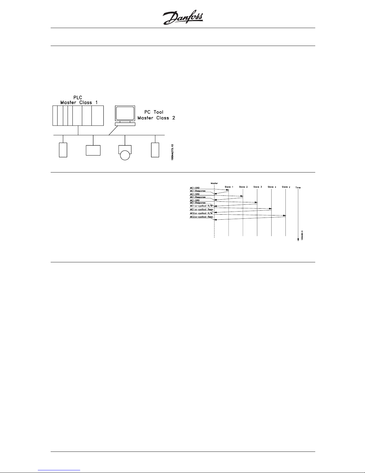
■Profibus DP V1
The Profibus DP extension DP V1 offers additional
to the cyclical data communication an acyclical
communication. This feature can be used by a
DP master type 1 (e.g. PLC), as well as a DP
master type 2 (e.g. PC tool).
Features of a Master type 1 connection
- Cyclical data exchange (DP V0).
- Acyclical read/write on parameters.
The acyclical connection is fixed, and can not
be changed during operation.
Features of a Master type 2 connection:
- Initiate / Abort acyclical connection.
- Acyclical read/write on parameters.
The acyclical connection can dynamically be
established (Initiate) or removed (Abort) even when
a master class 1 is active on the network.
The DP V1 acyclical connection can be used
for general parameter access as an alternative
to the PCV parameter channel.
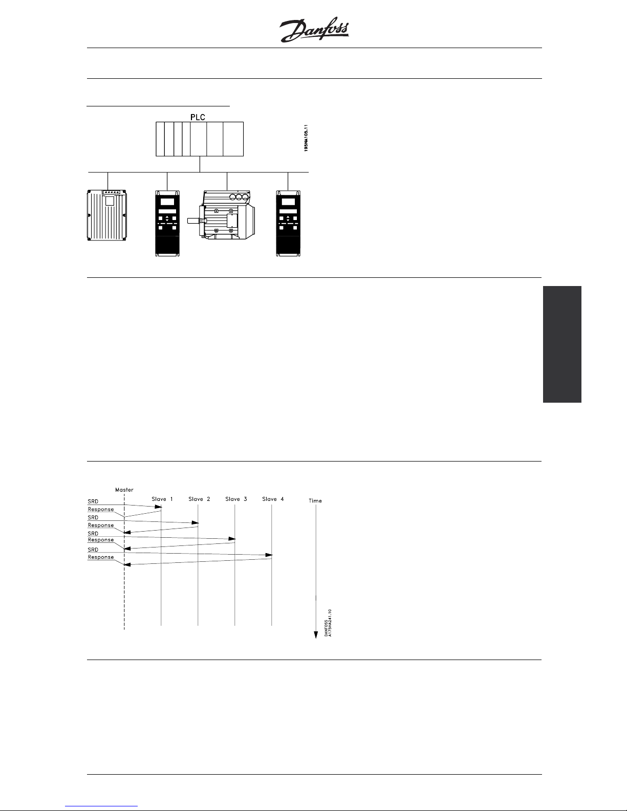
■PrincipleofdataexchangebyProfibusDPV0/DPV1
In a DP cycle the MC 1 will first update the cyclical
process data for all slaves in the system. After that
the MC 1 has the possibility of sending one acyclical
message to one slave. If a MC 2 is connected,
the MC 1 will handle over the Token to MC 2 who
now is aloud to send one acy clical message to one
slave. After that, the token is handled back to the
MC 1, and a new DP cycle is started.
MC1: Master Class 1
MG.90.G1.02 - VLT is a registered Danfoss trademark
8
Page 10
VLT® 5000/ 5000 FLUX/ 6000 HVAC/
8000 AQUA PROFIBUS
The PROFIBUS option
card
■Cable lengths and number of nodes
The maximum cable length of a segment depends on
the transmission speed. The total cable length includes
stub lines, if applicable. A stub line is the connection
from the main bus cable to each node if a "T"
connection exists instead of a direct connection of the
main bus cable to the nodes; cf. the stub line length.
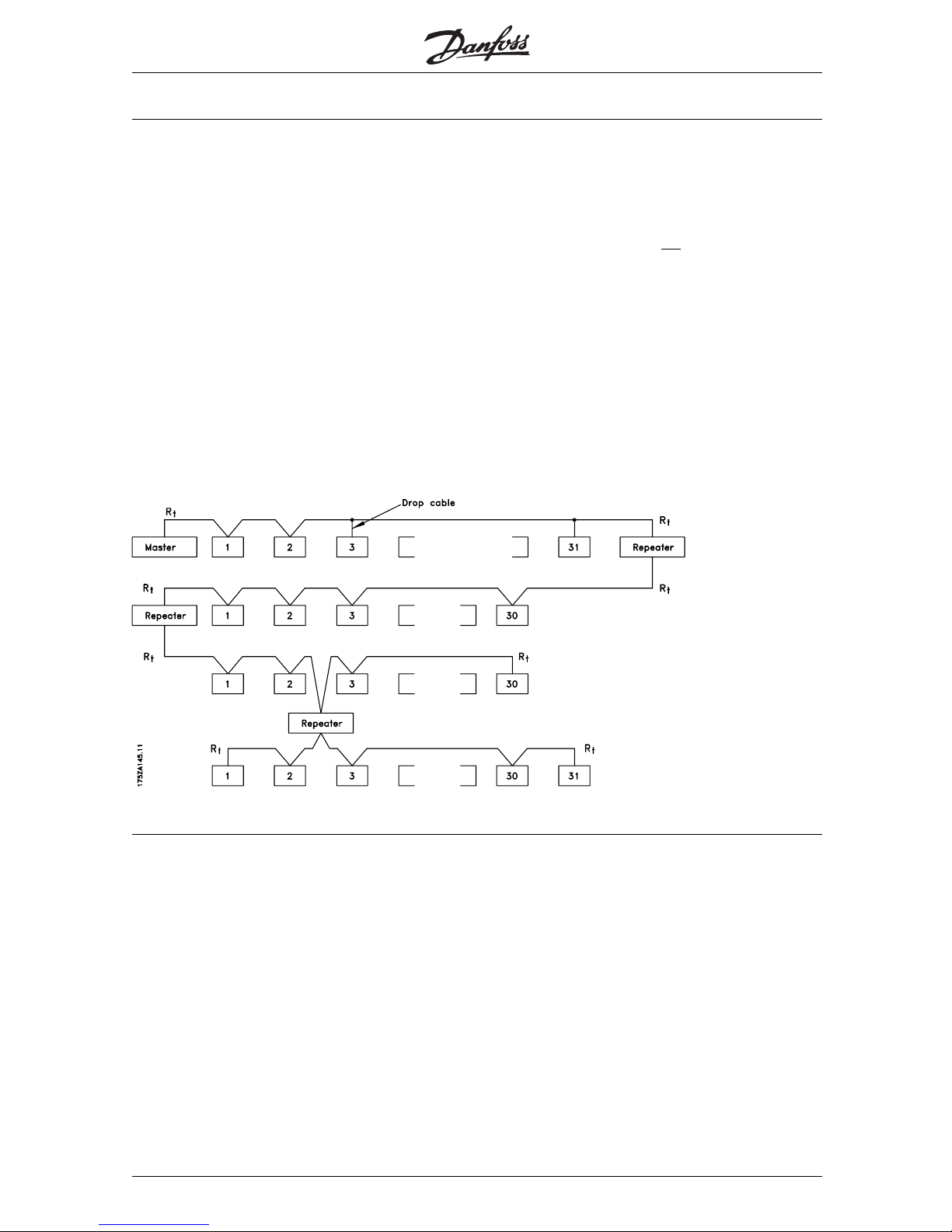
The following table s hows the maximum permitted
cable lengths and the maximum number of nodes or
frequency converters with 1, 2, 3 or 4 bus segments.
Please note that a repeater switched between two
segments represents a node in both segments.
The number of frequency converters is based on
a system with only one master. In the case of
multiple masters, the number of frequency converters
must be reduced accordingly.
The total stub line l ength of a segment is
limited as follows:
Stub line length
Transmission speed Max. stub line length
per segment [m]
9.6-93.75 kBaud 96
187.5 kBaud 75
500 kBaud 30
1.5 MBaud 10
3-12 MBaud none
Maximum total bus cable length
Transmission speed 1 segment:
32 nodes (31
frequency converters)
[m]
2segments:
64 nodes (1 repeater,
61 frequency
converters) [m]
3segments:
96 nodes (2 repeater,
91 frequency
converters) [m]
4segments:
128nodes(3repeater,
121 frequency
converters) [m]
9.6-187.5 kBaud 1000 2000 3000 4000
500 kBaud 400 800 1200 1600
1.5 MBaud 200 400 600 800
3-12 MBaud 100 200 300 400
MG.90.G1.02 - VLT is a registered Danfoss trademark
9
Page 11
VLT® 5000/ 5000 FLUX/ 6000 HVAC/
8000 AQUA PROFIBUS
The indicated lengths in the tables are valid
on the condition that bus cables with the
following properties are used:
- Impedance: 135 to 165 Ohm at a measuring
frequency of 3 to 20 MHz
- Resistance: < 110 Ohm/km
- Capacity: < 30 pF/m
- Damping: max. 9 dB across the entire
cable length
- Cross-section: max. 0.34 mm pursuant to
AWG 22
- Wire type: twisted pair, 1 x 2 or 2 x 2 or 1
x4conductors
- Shielding copper-braided or braided and
foil laminated
It is recommended to use the same cable type
throughout the entire network in order to avoid
mismatches of the impedance.
The figures in the following description indicate the
maximum permitted number of stations in each
segment. These figures do n
ot refer to the station
addresses, since each station in the network must
have an unambiguous address.
Segment 1
Segment 2
Segment 3
Segment 4
MG.90.G1.02 - VLT is a registered Danfoss trademark
10
Page 12
VLT® 5000/ 5000 FLUX/ 6000 HVAC/
8000 AQUA PROFIBUS
The PROFIBUS option
card
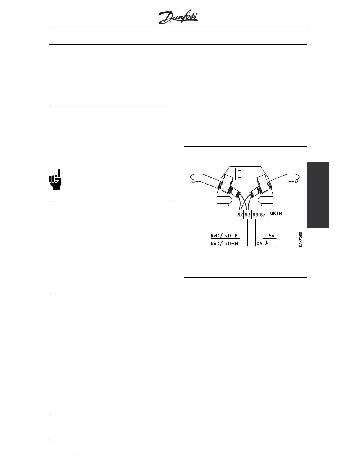
■Physical connection
The PROFIBUS option card will be connected to the
bus line (data line) at terminals 62 and 63. Data line
"B" (TxD/RxD-P) will be connected to terminal 62 and
data line "A" (TxD/RxD-N) to terminal 63. A master
with a voltaically insulated bus driver and overvoltage
protection (e.g. Z diode) is recommended.
■Protective measures for EMC
It is recommended to carry out the following protective
measures for EMC in order to ensure a trouble-free
operation of the PROFIBUS network. Additional notes
concerning the subject of EMC can be found in the
project manual for the VLT 5000 series (MG.50.Cx.yy)
and in the manual for the Profibus master.
NB!:
The applicable national and local regulations,
for example with respect to protective
earthing, must be observed.
■Cable connection FCM 300
The PROFIBUS communication cable must be kept
away from motor and brake resistor cables to avoid
coupling of high frequency noise from one cable to
the other. Normally a distance of 200 mm is sufficient,
but it is generally recommended to keep the greatest
possible distance between the cables, especially where
cables are running in parallel over long dista
nces.
If the PROFIBUS cable has to cross a motor and
braking resistance cable, it should occur at a 90° angle.
■Connection of the cable screening
The shielding of the PROFIBUS cable always needs
tobeofalarge-area,low-impedancetypeonboth
sides. As a matter of principle, the screen should be
put up with a large area and low impedance at all
PROFIBUS stations. It is very important to have an
earthconnectionwithlowimpedanceevenathigh
frequencies. This can be achieved by connecting the
shield surface to earth, for example with the help of
a cable bow or a conductive cable connector.
The frequency converter is equipped with various
terminals and supports in order to provide a flawless
shielding of the PROFIBUS ca
ble. The shield
connection is shown in the following diagram.
■Earthing
It is important to connect all stations linked to the
PROFIBUS network to the same earth potential. The
earthing must have a low high-frequency impedance.
This can be achieved by connecting a protective
housing surface which is as large as possible to
earth, for example by mounting the frequency
converter to a conductive rear wall.
Especially in the case of large distances between the
stations of a PROFIBUS network, the additional use of
potential equalization cables to connect the individual
stations to the same earth potential may be necessary.
■Bus connection
62 = RxD/TxD-P red cable
63 = RxD/TxD-N green cable
MG.90.G1.02 - VLT is a registered Danfoss trademark
11
Page 13
VLT® 5000/ 5000 FLUX/ 6000 HVAC/
8000 AQUA PROFIBUS
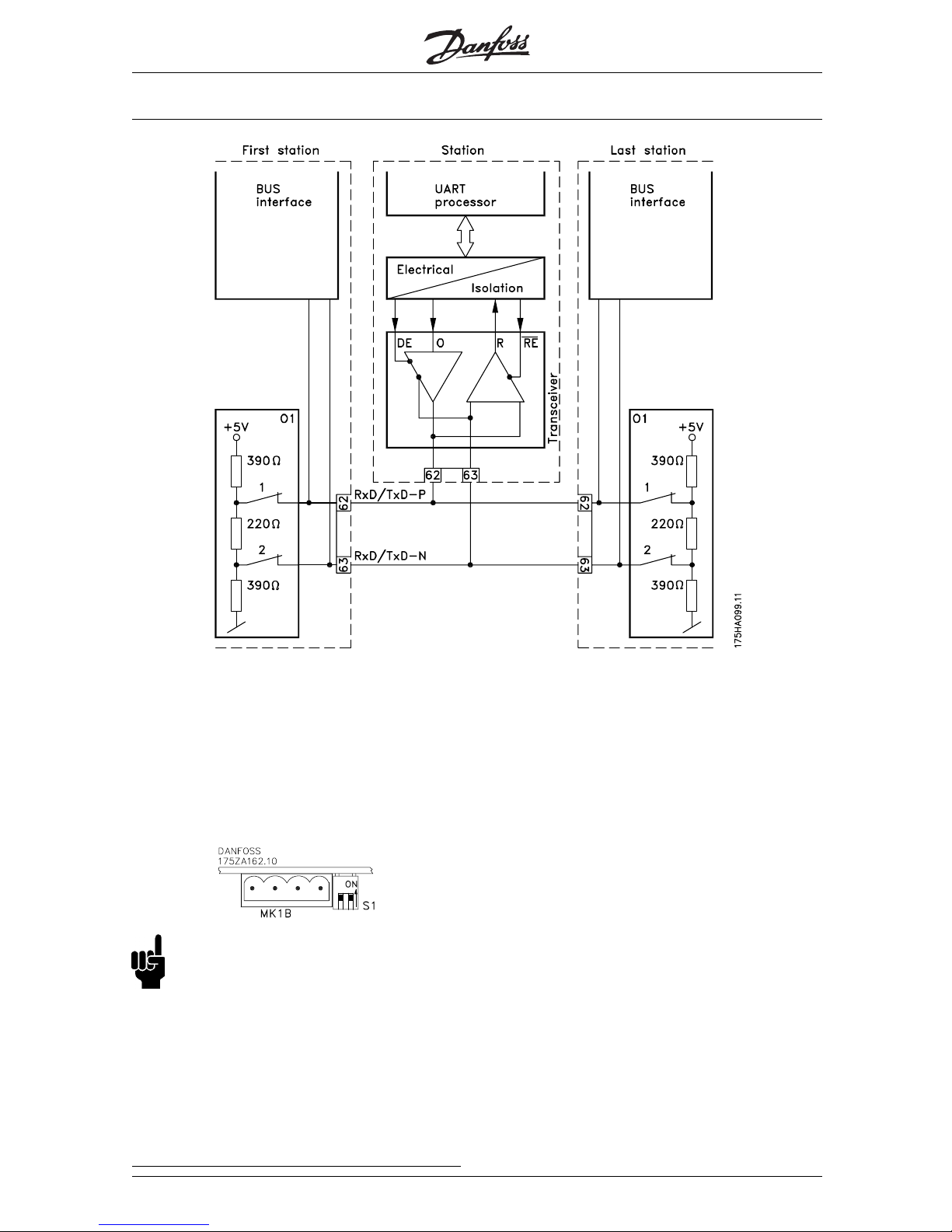
■Diagram bus connection
It is important to terminate the bus line correctly.
Mismatches of the impedance may lead to reflections
in the line and cause incorrect transmissions.
- The PROFIBUS option card is equipped with a
suitable termination which can be activated by
theswitches1and2attheswitchblockS1
directly to the right above the terminal block
MK 1B. The bus termination is active when the
switch is in the "ON" position.
NB!:
Th
e switches must never be set in
opposite directions. Both switches must
be set to ON or OFF.
- Most masters and repeaters are equipped
with their own termination.
- If an internal termination circuit in the form of
three resistors is connected to the bus line, a
5 V direct voltage must be used. Attention:
please make sure that it is voltaically separated
from the power supply cable.
MG.90.G1.02 - VLT is a registered Danfoss trademark
12
Page 14
VLT® 5000/ 5000 FLUX/ 6000 HVAC/
8000 AQUA PROFIBUS
The PROFIBUS option
card
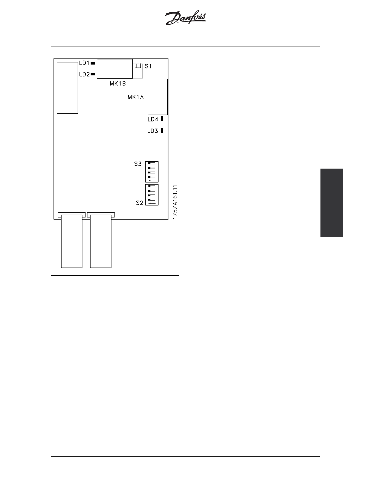
■The PROFIBUS option card ■LEDs
There are four LEDs on the PROFIBUS option card:
LD1 and LD4: Flickering (very rapid blinking),
when data are being exchanged
through the option card.
Comment: with each "flicker" of
the LEDs, the frequency converter
is sending a telegram.
LD2 and LD3: Shining, when the option card
is initialized and ready for the
data exchange, or when data
are already being exchanged.
Blinking, when the function
for the automatic baud rate
determination attempts to
determine the current baud rate.
Note: a faulty connection of the
data line may also cause blinking
of the LEDs. (see "Physical
connection").
MG.90.G1.02 - VLT is a registered Danfoss trademark
13
Page 15
VLT® 5000/ 5000 FLUX/ 6000 HVAC/
8000 AQUA PROFIBUS
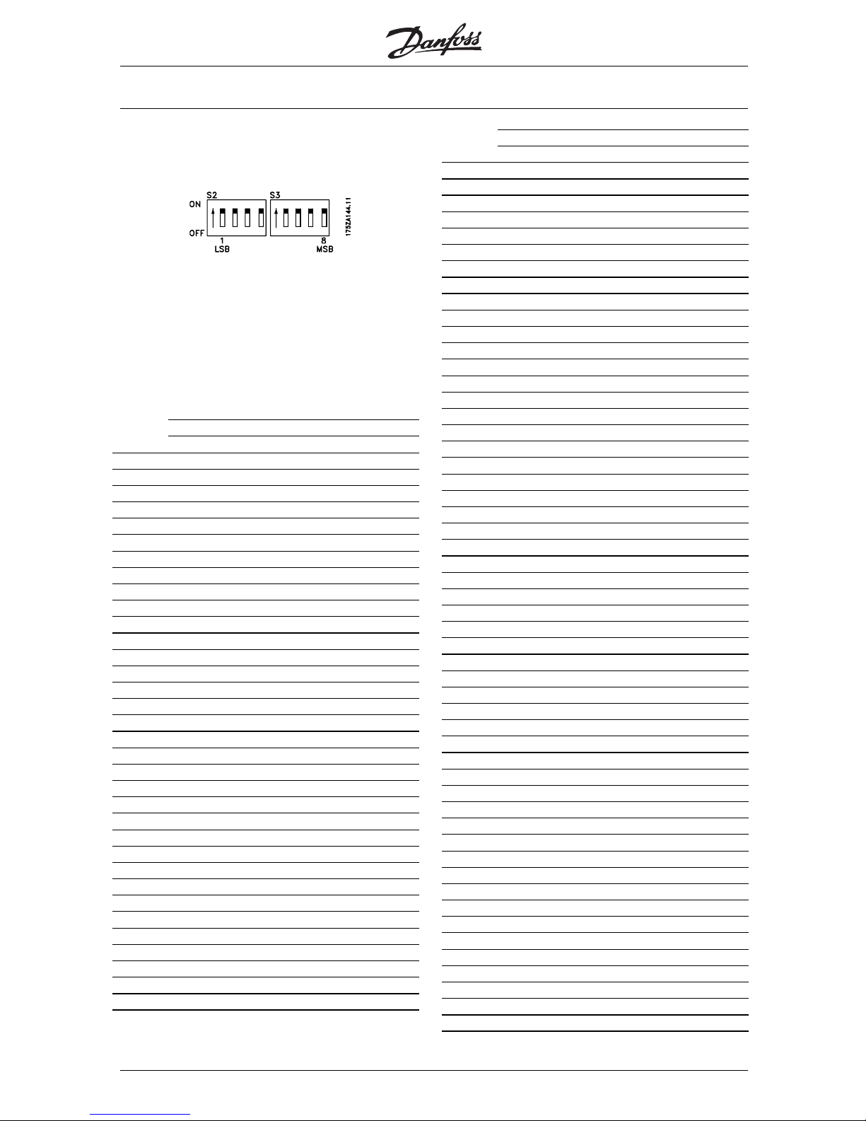
■Address switches
The station address can be set in parameter 918
or through a hardware switch (S2, 1-4 and S3,
5-7 on the PROFIBUS option card).
The setting of an address through parameter 918 is only
possible when the address switches are set to > 125.
Each slave must have an unambiguous address.
The address is the binary value set for the switches,
cf. the table below. The modification of the address
switches occurs during the next turn-on procedure.
See also section Station Address.
Switches 1-7 (switch 8 is not used)
1234567
Addressswitchposition(1=ON,0=OFF)
00000000
11000000
20100000
31100000
40010000
51010000
60110000
71110000
80001000
91001000
100101000
111101000
120011000
131011000
140111000
151111000
160000100
171000100
180100100
191100100
200010100
211010100
220110100
231110100
240001100
251001100
260101100
271101100
280011100
291011100
300111100
311111100
320000010
331000010
Switches 1-7 (switch 8 is not used)
1234567
Address switch position (1= ON, 0=OFF)
340100010
351100010
360010010
371010010
380110010
391110010
400001010
411001010
420101010
431101010
440011010
451011010
460111010
471111010
480000110
491000110
500100110
511100110
520010110
531010110
540110110
551110110
560001110
571001110
580101110
591101110
600011110
611011110
620111110
631111110
640000001
651000001
660100001
671100001
680010001
691010001
700110001
711110001
720001001
731001001
740101001
751101001
760011001
771011001
780111001
791111001
800000101
811000101
820100101
831100101
840010101
851010101
860110101
MG.90.G1.02 - VLT is a registered Danfoss trademark
14
Page 16

VLT® 5000/ 5000 FLUX/ 6000 HVAC/
8000 AQUA PROFIBUS
The PROFIBUS option
card
Switches 1-7 (switch 8 is not used)
1234567
Addressswitchposition(1=ON,0=OFF)
871110101
880001101
891001101
900101101
911101101
920011101
931011101
940111101
951111101
960000011
971000011
980100011
991100011
1000010011
1011010011
1020110011
1031110011
1040001011
1051001011
1060101011
1071101011
1080011011
1091011011
1100111011
1111111011
1120000111
1131000111
1140100111
1151100111
1160010111
1171010111
1180110111
1191110111
1200001111
1211001111
1220101111
1231101111
1240011111
1251011111
1260111111
1271111111
MG.90.G1.02 - VLT is a registered Danfoss trademark
15
Page 17
VLT® 5000/ 5000 FLUX/ 6000 HVAC/
8000 AQUA PROFIBUS
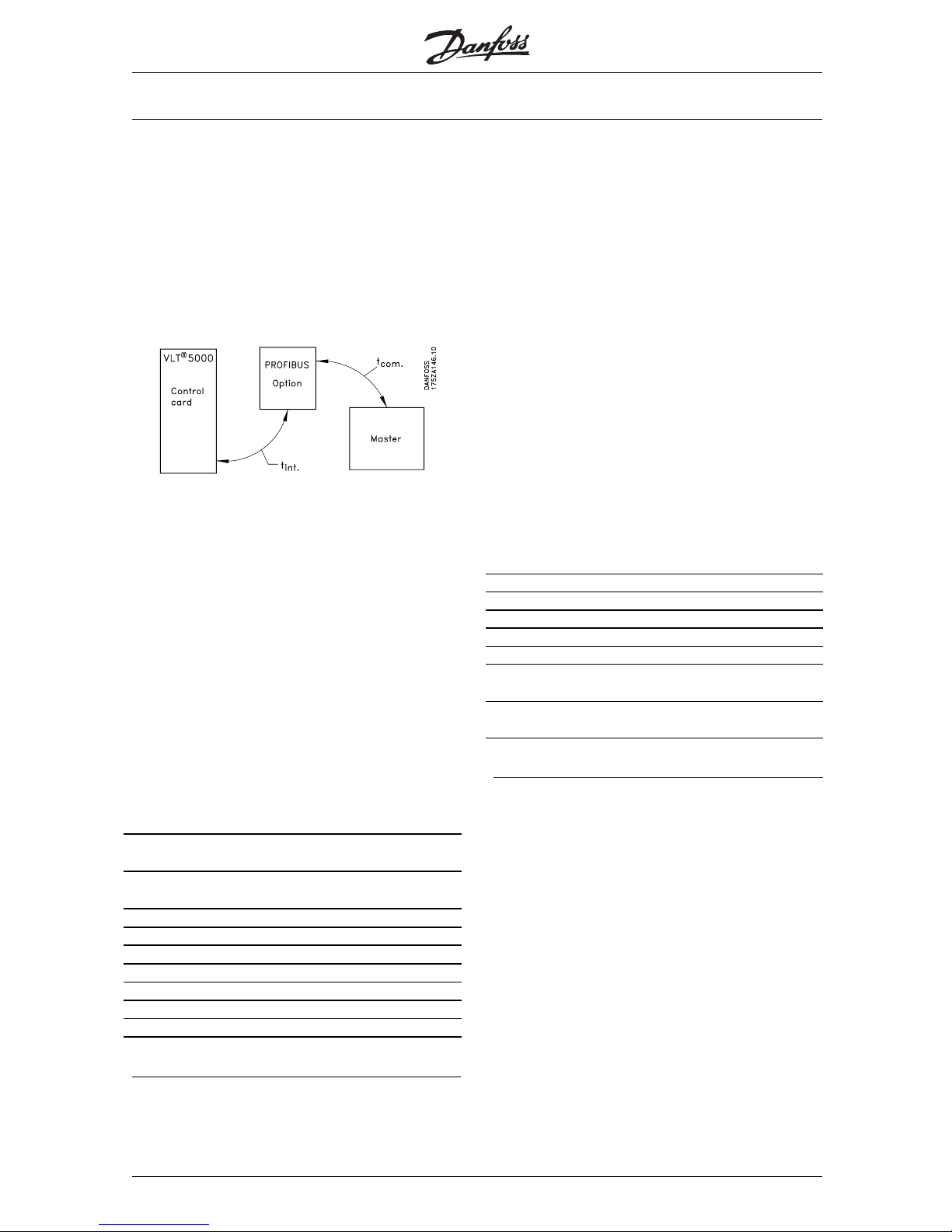
■Timing
■Frequency converter response time behaviour
The period for the update through the PROFIBUS
connection can be subdivided into two portions:
1. The communication period, i.e. the time required
to transmit data from the master to the slave
(frequency converter with PROFIBUS option), and
2. the internal update period, i.e. the time required
to transmit data between the frequency converter
control card and t he PROFIBUS option card.
The communication period (t
com
) depends on the
respective transmission speed (baud rate) and the
type of master being used. The shortest achievable
communication period is approximately 30 msec
per slave with the frequency converter PROFIBUS
option when DP communication with a data quantity
of 4 bytes (PPO type 3) at 12 Mbaud is used.
The communication period increases with more
data or lower transmission speeds.
The internal update period (t
int
) depends on the
respective data as there are different channels
for the transmission of data, with time-critical
data, such as the Control word, being given the
highest priority. The internal update time for the
respective data types is listed below.
Data Update time,
t
int
Control word/main reference
value (Part of PPO)
2msec.
Status word/respective output
frequency (Part of PPO)
2msec.
Parameter Read (PCD 1-8) 2 msec.
Parameter Write (PCD 1-2) 40 msec.
Parameter Write (PCD 3-4) 80 msec.
Parameter Write (PCD 5-8) 160 msec.
Parameter Read (PCV) 20 msec.
Parameter Write (PCV) 20 msec.
Acyclical data (read, write) 20 msec.
■Time behaviour during system update
Thesystemupdateperiodisthetimerequired
to update all slaves of the network when cyclical
communication is used.
The update time of a single slave is composed of both
the communication period (depending on the baud
rate) and the station delay (TSDR) in the slave, and of
the delay in the master associated with the station.
The station delay (TSDR) is the delay time from the
moment when a station receives the last bit of a
telegram to the moment when it sends the first bit
of the next telegram. The station delay is defined by
two parameters: the minimum station delay (TSDR
min
)
and the maximum station delay (TSDR
max
).
Current station delay for the PROFIBUS option:
-DP:11bittimes
Current master station delay:
- This information must be provided by the
manufacturer of the respective PROFIBUS master.
Example
- DP master with 1.5 MBaud and PPO type
3 (4 byte data); the assumption here is for 50
bit times as master TSDR.
Time [msec] Action
0 Master starts data transmission
Last bit received in slave
Slave station delay
Slave starts data transmission
Last bit received in master
Master station delay
(50 bit times » 0.033)
Master ready for data transmission
to next slave
MG.90.G1.02 - VLT is a registered Danfoss trademark
16
Page 18
VLT® 5000/ 5000 FLUX/ 6000 HVAC/
8000 AQUA PROFIBUS
PPO
description
■Communication connections
Communication pursuant to PROFIBUS DP , i.e.
EN50170 part 3, is supported.
Accordingly, a master must be used that
supports PROFIBUS DP.
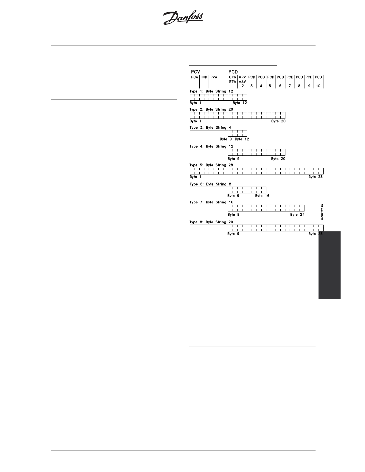
■PPO description (Overview)
A feature of the PROFIBUS profile for frequency
converters is a communications object designated as
"PPO", i.e. "parameter process data object".
All cyclical informative data are transmitted via PPOs.
Thus, PPOs form the framework for the data traffic.
One of the PPOs described in the following must be
used in the case of DP communication.
The actual PPO type can be readout in parameter 904.
A PPO may consist of a parameter portion and
a process data portion. The parameter portion
may be used for reading and/or updating of
parameters (successively).
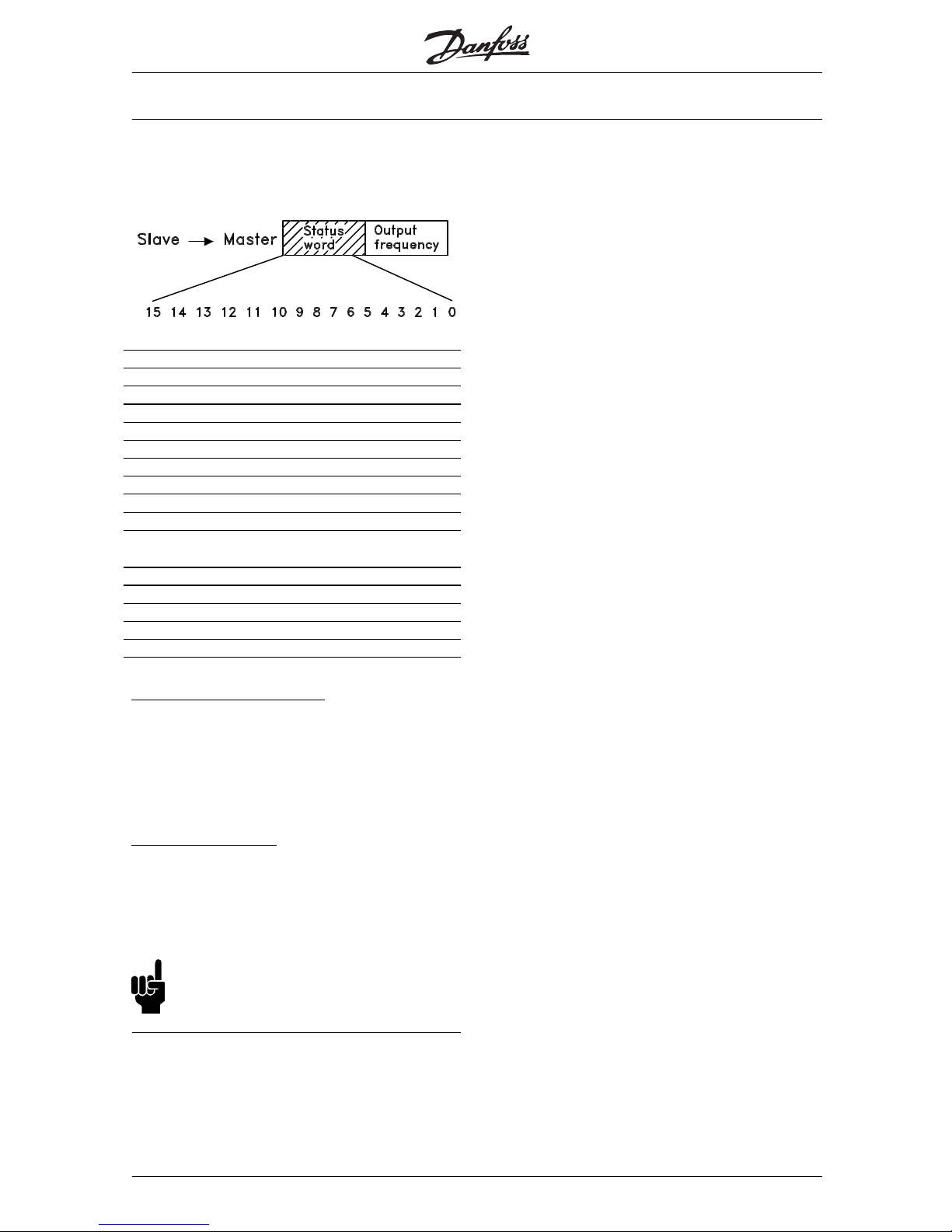
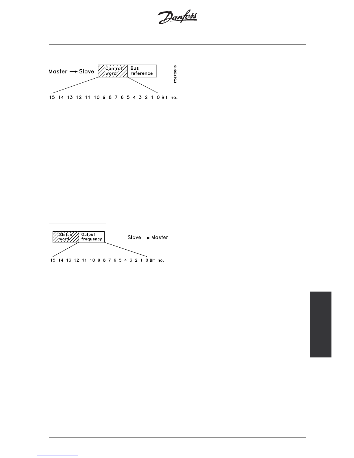
The process data portion consists of a fixed part
(4 bytes) and a parameterizable part (8 or 16
bytes). The Control word and speed reference
value are transmitted to the frequency converter
in the fixed portion, whereas the Status word
and current output frequency are transmitted by
the frequency converter. In the parameterizable
portion, the user selects which parameters are to be
transmitted to the frequency converter (parameter
915) and which are to be transmitted by the
frequency converter (parameter 916).
P
PO, Parameter Process Data Object
PDC: Process Data
PCV: Parameter-Characteristics-Value
PCA: Parameter-Characteristics (Bytes 1, 2)
PCA handling see section Examples
IND: Subindex (Byte 3)m (Byte 4 is not used)
PVA: Parameter value (Bytes 5 to 8)
CTW: Control
word
STW: Status
word
See section Examples
MRV: Main reference value
MAV: Main actual value (Actual output
frequency)
MG.90.G1.02 - VLT is a registered Danfoss trademark
17
Page 19
VLT® 5000/ 5000 FLUX/ 6000 HVAC/
8000 AQUA PROFIBUS
■PCA processing
The master controls and monitors frequency converter
parameters through the PCA portion of the PPOs
type 1, 2 and 5 and requests a response from
the frequency converter (slave). In addition to the
parameter processing, the frequency converter can
also transmit a spontaneous message.
Requests and responses involve an acknowledgement
exchange (a so-called handshake) which cannot be
worked off in stack operation. This means that the
master, when sending a read/write request, must wait
for the response before sending a new request. A
request or response is limited to a maximum of 4
bytes, i.e. no text strings can be transmitted.
PCA - Parameter description
15 14 13 12 11 109876543210
RC MSP PNU
RC: Request/Response
Characteristics
(Sector: 0-15)
SPM: Toggle bit for spontaneous
messages
PNU: Parameter Number (Sector: 1-990)
Request and response
In the RC portion of the PCA word the requests of the
mastertotheslavearetriggered.TheothertwoPCV
fields IND and PVA must be evaluated as well.
The PVA po
rtion transmits parameter values in
word size with the bytes 7 and 8; double words
require the bytes 5-8, i.e. 32 bits.
If the request or response contains array elements,
thearraysubindexwillbeinIND(byte3). In
the event of a parameter description, IND
contains the record subindex.
RC content
Request Function
0Norequest
1 Request parameter value
2 Change parameter value (word)
3 Change parameter value (double word)
4 Request description element
5 Change description element
6 Request parameter value (array)
7 Change parameter value (array word)
8 Change parameter value (array double
word)
9 Request number of array elements
10-15 Not assigned
Response
Function
0Noresponse
1 Transmit parameter value (word)
2 Transmit parameter value (double
word)
3 Transmit description element
4 Transmit parameter value (array word)
5 Transmit parameter value (array double
word)
6 Transmit number of array elements
7 Request not executable (with error
number, see below)
8 No operating authority for PCV
interface
9 Spontaneous message (word)
10 Spontaneous message (double word)
11 Spontaneous message (array word)
12 Spontaneous message (array double
word)
13-15 Not assigned
If a request from the master is not executed by the
slave, the RC word in the PPO-Read has the value 7.
The errornumber is in bytes 7 and 8 of the PVAelement.
Error no. Meaning
0
1 Parameter value not changeable
2 Upperorlowervaluepassed
3Faultysubindex
4Noarray
5 Wrong data type
6 Setting not permitted (resettable only)
7 Description element not changeable
8 NoPPO-WriteforIR
9 Description data not available
10 Access group
11 No parameter operating authority
12 Keyword missing
13 Text not readable in cyclical traffic
14 Name not readable in cyclical traffic
15 Text array not available
16 PPO-Write missing
17 Request temporarily unexecutable
18 Other error
19 Data not readable in cyclical traffic
MG.90.G1.02 - VLT is a registered Danfoss trademark
18
Page 20

VLT® 5000/ 5000 FLUX/ 6000 HVAC/
8000 AQUA PROFIBUS
■Parameters and data type structures
■Parameter description
Parameters which areaccessible throughtheparameter
number (PNU) have additional attributes that are a
component of the accompanying descriptive element.
Writing/reading of a p arameter description occurs
through the PCV portion by means of the RC
commands 4/5 and the subindex of the desired
descriptive element (see accompanying diagram).
Characteristics
The "characteristics" subindex extends the definition of
the parameter description. The individual bits 9 to 15
have the values TRUE [1] or FALSE[0](see table below).
Bit Meaning
15 Active parameter
14 Array
13 Parameter value resettable only
12 Factory setting of parameter c hanged
11 Text available
10 Additional text array available
9 No write access (read only)
8 Lower and upper limit. Standardization
and size attribute not relevant.
0-7 Datatypeoftheparametercorresponds
to OD
The low byte (bit 0-7) indicates the data type of
the parameter (see following table).
NB!:
The "data type" for each parameter can
be found in the corresponding colu mn in
the chapter parameter listing.
Data types supported by the frequency converter
Data
type
Object Short form Description
3 5 12 Integer 16
4 5 12 Integer 32
55 Unsigned8
6 5 02 Unsigned 16
7 5 04 Unsigned 32
95 Visiblestring
10 5 Byte string
33 5 N2 Standardization
value (16 bit)
1)
35 5 V2 Bit sequence
1) See following page for details
Example: Data type 5 = Unsigned 8
S
ize attribute
Thesizeattributeis2byteslong.
Byte 1 incorporates the physical unit of measurement
(sizeindex),byte2theconversionindex.
NB!:
The "conversion index" for each parameter
can be foun d in the corresponding column
in the chapter parameter listing.
The "conversion index" produces the conversion
factor for each parameter.
Example:
Parameter
205:
Conversion index = -3 <=> (10E-3
Conversion factor: 0.001
15200 = 15.200 Hz
An except from the PROFIDRIVE profile with
respect to the assignment of the size index and
the conversion index to the physical size can
be found on the following page.
S
tandardized value
A linear value 0% = 0 (0h), 100% are 214 (4000h)
Data type N 2
Range -200% ... 200% - 2
-14
Resolution 2
-14
= 0,0061%
Length 2 bytes
Note: Two’s complement notation
MSB is the first bit after the sign bit of the first byte.
Sign bit = 0 = positive number
Sign bit = 1 = negative number
MG.90.G1.02 - VLT is a registered Danfoss trademark
19
Page 21

VLT® 5000/ 5000 FLUX/ 6000 HVAC/
8000 AQUA PROFIBUS
Bit 8 7 6 5 4 3 2 1
Byte2SIGN 2
142132122112102928
Byte
1
2
7
2
6
25242322212
0
Physical size Size index Unit of
measurement
Abbreviation Conversion
index
Conversion factor
0Nodimension 0 1
Time Second s 0 1
-1 0.1
-2 0.01
Millisecond ms -3 0.001
Minute min 70 60
Hour h 74 3600
4
Day d 77 86400
Energy Watt-hour Wh 0 1
Kilowatt-hour kWh 3 10008
Megawatt-hour MWh 6 10
Power Milliwatt mW -3 0.001
Watt W 0 1
Kilowatt kW 3 1000
9
Megawatt MW 6 10
Rotation 11 Revolutions per
minute
RPM 0 1
Torque Newtonmeter Nm 0 1
16
Kilonewtonmeter
kNm 3 1000
Temperature 17 Degree Celsius °C 0 1
Voltage Millivolt mV -3 0.001
Volt V 0 121
Kilovolt kV 3 1000
Current Milliampere mA -3 0.001
Ampere A 0 122
Kiloampere kA 3 1000
Resistance Milliohm mOhm -3 0.001
Ohm Ohm 0 123
Kiloohm kOhm 3 1000
Relation 24 Percent % 0 1
Relative change 27 Percent % 0 1
Frequency Hertz Hz 0 1
Kilohertz kHz 3 100028
Megahertz MHz 6 10
MG.90.G1.02 - VLT is a registered Danfoss trademark
20
Page 22

VLT® 5000/ 5000 FLUX/ 6000 HVAC/
8000 AQUA PROFIBUS
Spontaneous
messages
■Spontaneous messages
The spontaneous message is triggered by the active
alarm and warning words parameters in the actual
drive. The PCV response indicates the parameter
number (PNU) and the parameter value (PVA) of the
modified active parameter that triggered the message.
Spontaneous messages are generated when active
parameters are changed, i.e. a message occurs when
a warning appears and when a warning disappears.
At the same time, the frequency converter modifies the
SPM bit (11) of the PCV word (see "PCA processing").
The spontaneous messages are transmitted
until the master has confirmed the receipt of the
message and changed the SPM bit.
NB!:
Spontaneous messages are only activated when
the parameter 917 is in the "ON" position. In the
event of an activated spontaneous message,
the parameter channel is blocked until the spontaneous
message has been acknowledged by the master.
Example of a spontaneous message for VLT 5000
Observation of the parameter channel (PCV) from the PPO (without index field):
PCV (Hex) PVA (Hex) from Master from
frequency
converter
Description
12 08 00 00 00 00 x The master requests the current of the
frequency converter
12 08
00 00 00 F0 x The frequency converter current value: 2.4
Amp (parameter 520)
12 08
00 00 00 00 x The master requests the current of the
frequency converter
AC 1A
00 00 00 0A x The frequency converter has a spontaneous
message, the spontaneous message bit is set,
the PNU 538 (alarm word) has the value 000A
(Hex)
1C 08
00 00 00 00 x The master requests the current of the
frequency converter and acknowledges the
spontaneous message by "toggling" the SPM
in the PCV
1C 08
00 00 00 F0 x The frequency converter current value: 2.4
Amp, the spontaneous message bit remains at
"1" until the next spontaneous message; the
spontaneous message is acknowledged.
The frequency converter saves up to 16 consecutively
transmitted SPMs in a FIFO buffer. If only one SPM is
in the FIFO buffer, the frequency converter immediately
resumes normal operations after the master has
acknowledged it (and the cause of the SPM has been
eliminated). If there is more than one SPM in the FIFO
buffer , the transmission takes place one after the other
following the acknowledgement. Additional SPMs that
are generated while the buffer is full will be ignored.
MG.90.G1.02 - VLT is a registered Danfoss trademark
21
Page 23

VLT® 5000/ 5000 FLUX/ 6000 HVAC/
8000 AQUA PROFIBUS
■SYNC and FREEZE
The control commands SYNC/UNSYNC
(SYNCHRONIZE/CANCEL SYNCHRONIZATION)
and FREEZE/UNFREEZE are broadcast functions.
SYNC/UNSYNC is used to transmit synchronized
control commands and/or speed reference values
to all connected slaves. FREEZE/UNFREEZE
is used to freeze the status actual value in the
slaves in order to receive a synchronized actual
value from all connected slaves.
The SYNC and FREEZE commands refer to the
PCD and PCV portions of the PPO.
■SYNC/UNSYNC
By using SYNC/UNSYNC, simultaneous responses of
several slaves can be generated, e.g. synchronized
start, stop, or change of the speed. In the event of a
SYNC command, the current Control word and the
speed reference value are frozen. Incoming process
data are saved, but are only applied when a new SYNC
command or an UNSYNC command is made.
The following example shows the speed reference
value sent by the master in the left column and the
respective effective speed reference value for the three
slaves in the three columns to the right.
Current speed reference value slave
From DP master to address: VLT
Address 3
VLT
Address 4
VLT
Address 5
1. Speed reference value = 50% to address 3
⇒
50% 0% 0%
2. Speed reference value = 50% to address 4 50%
⇒
50% 0 %
3. Speed reference value = 50% to address 5 50% 50%
⇒
50%
4. SYNC command to all addresses
⇒
50%
⇒
50%
⇒
50%
5. Speed reference value = 75% to address 3
⇒
50% 50% 50%
6. Speed reference value = 75% to address 4 50%
⇒
50% 50%
7. Speed reference value = 75% to address 5 50% 50%
⇒
50%
8. SYNC command to all addresses
⇒
75 %
⇒
75 %
⇒
75 %
9. Speed reference value = 100% to address 3
⇒
75 % 75 % 75 %
10. Speed reference value = 50% to address 4 75 %
⇒
75 % 75 %
11. Speed reference value = 25% to address 5 75 % 75 %
⇒
75 %
12. UNSYNC command to all addresses
⇒
100 %
⇒
50 %
⇒
25 %
13. Speed reference = 0% to address 3
⇒
0% 50% 25%
14. Speed reference = 0% to address 4 0 %
⇒
0% 25%
15. Speed reference = 0% to address 5 0 % 0 %
⇒
0%
■FREEZE/UNFREEZE
By using FREEZE/UNFREEZE, simultaneous reading of
process data, e.g. output current, by several slaves
canbebroughtabout.AtaFREEZEcommand,the
actual current values are frozen. When instructed, the
slave will send back the value in effect at the time
the FREEZE command was issued. The respective
values are updated when a new FREEZE command
or an UNFREEZE command is issued.
The following example shows the current values read
by the master in the left column and the respective
effective value of the output current for the three
slaves in the three columns to the right.
Actual output current slave
VLT VLT VLT
DP master reads address: Address 3 Address 4 Address 5
1. Address 3 output current = 2 A ⇐ 2A 3A 4A
2. Address 4 output current = 5 A 2 A ⇐ 5A 2A
3. Address 5 output current = 3 A 3 A 2 A ⇐ 3A
4. FREEZE command to all
addresses
⇒
1A
⇒
3A
⇒
3A
5. Address 3 output current = 1 A ⇐ 4A 2A 5A
6. Address 4 output current = 3 A 2 A ⇐ 2A 2A
7. Address 5 output current = 3 A 3 A 1 A ⇐ 2A
8. UNFREEZE command to all
addresses
⇒
2A
⇒
3A
⇒
4A
Readout same as for 1, 2 and 3
MG.90.G1.02 - VLT is a registered Danfoss trademark
22
Page 24

VLT® 5000/ 5000 FLUX/ 6000 HVAC/
8000 AQUA PROFIBUS
Control word/Status
word
■Control word/Status word
The bits of the "Control word" tell the frequency
converter how to respond, while the status of the
bits in the "Status word" transmits information about
the frequency converter to the master.
One can select through parameter 512 whether
the Control word and Status word are to be
defined according to "Profidrive" (field bus) or
according to "FC Drive (Danfoss)". "FC Drive
(Danfoss)" is the factory setting.
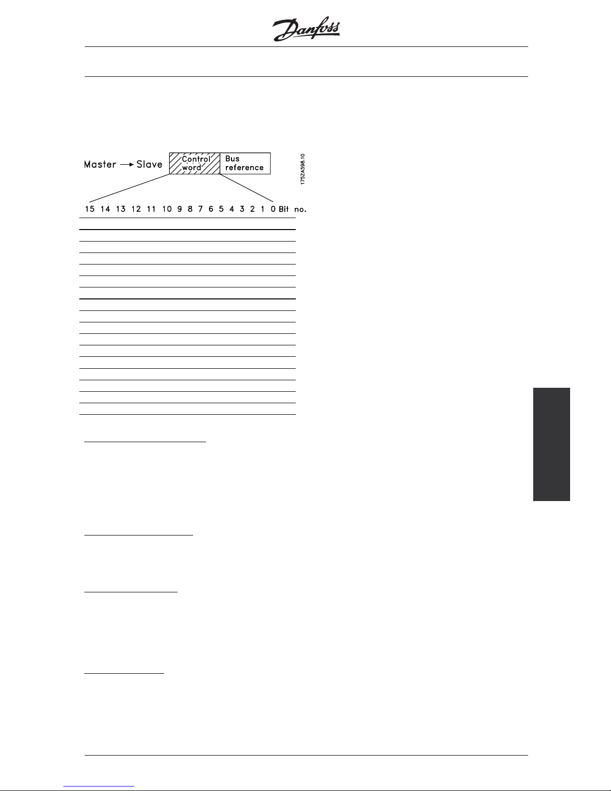
■Control word according to profidriveprofile
(Parameter 512 = field bus)
The Control word is used to send commands from
a master (e.g. a PC) to a slave.
Bit Bit = 0 Bit =1
00 OFF 1 ON 1
01 OFF 2 ON 2
02 OFF 3 ON 3
03 Coasting stop No coasting
04 Quick stop Ramp
05 Save outp. frequency Ramp possible
06 Ramp stop Start
07 Without function Reset
08 Jogging speed 1 OFF ON
09 Jogging speeed
2OFF
ON
10 Data not valid Valid
11 Without function Frequ. correction
DOWN (reduce)
12 Without function Frequ. correction UP
(increase ref. value)
13 Selection setup 1 (lsb)
14 Selection setup
2(msb)
15 Without function Reversion
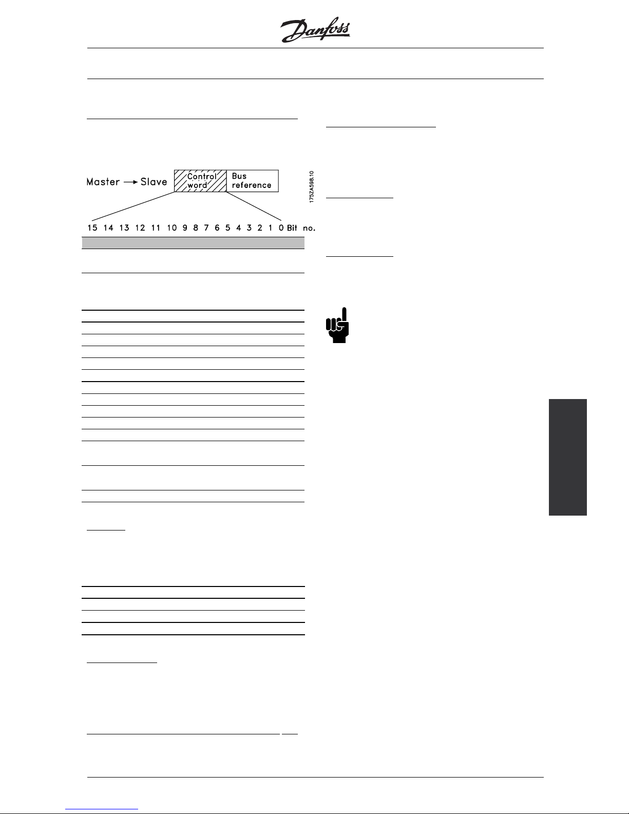
NB!:
If "Fieldbus" has been selected, then a two-part
start command has to be observed when the
start is released (turn-on lock-out: bit 0).
For this it is necessary to first predetermine Hex 047E
and then Hex 047F in the Control word, for example.
15 14 131211 10 9 8 7654 3210 Bit no.
0
4 7 E (Hex)
0
4 7 F (Hex)
Bit 00 OFF/ON 01:
Normal ramp stop using the ramp times of the
parameters 207/ 208 or 209/210.
Bit 00 = "0" leads to the stop and activation of the
output relay 01 or 04 if the output frequency is 0 Hz if
Relay 123 has been selected in parameter 323 or 326.
In the case of bit 00 = "1", the frequency converter can
start if the other start conditions are satisfied.
B
it 01, OFF 2/ON 2
Coasting stop
In the case of bit 01 = "0", a coasting stop and
activation of the output relay 01 or 04 occurs if
the output frequenc
y is 0 Hz if Relay 123 has been
selected in parameter 323 or 326.
In the case of bit 01 = "1", the frequency converter can
start if the other
start conditions are satisfied.
B
it 02, OFF 3/ON 3
Quick stop using the ramp time of parameter
212. In the case of bit 02 = "0", a quick stop and
activation of the output relay 01 or 04 occurs if
the output frequency is 0 Hz if Relay 123 has been
selected in parameter 323 or 326.
In the case of bit 02 = "1", the frequency converter can
start if the other start conditions are satisfied.
B
it 03, Coasting/No coasting
Coasting stop
Bit 03 = "0" l
eads to a stop.
In the case of bit 03 = "1", the frequency converter
can start if the other start conditions are satisfied.
Note: Th
e selection in parameter 502 determines
how bit 03 is linked with the corresponding
function of the digital inputs.
MG.90.G1.02 - VLT is a registered Danfoss trademark
23
Page 25

VLT® 5000/ 5000 FLUX/ 6000 HVAC/
8000 AQUA PROFIBUS
Bit 04, Quick stop/Ramp
Quick stop using t he ramp time of parameter 212.
In the case of bit 04 = "0", a quick stop occurs.
In the case of bit 04 = "1", the frequency converter
can start if the other start conditions are satisfied.
Note: The selection in parameter 503 determines
how bit 04 is linked with the corresponding
function of the digital inputs.
B
it 05, Save output frequency/Ramp possible
Inthecaseofbit 05 ="0", thecurrentoutputfrequencyis
being maintained even if the reference value is modified.
In the case of bit 05 = "1", the frequency converter can
perform its regulating function again; operation occurs
according to the respective reference value.
B
it 06, Ramp stop/Start
Normal ramp stop using the ramp times of the
parameters 207/208 or 209/210.
In addition, activation of the output relay 01 or 04
if the output frequency is 0 Hz if Relay 123 has
been selected in parameter 323 or 326.
Bit 06 = "0" leads to a stop.
In the case of bit 06 = "1", the frequency converter
can start if the other start conditions are satisfied.
Note: The selection in parameter 505 determines
how bit 06 is linked with the corresponding
function of the digital inputs.
B
it 07, Without function/Reset
Reset after switching off.
In the case of bit 07 = "0", no reset occurs.
In the case of a slope change of bit 07 to "1",
a reset occurs after switching off.
B
it 08, Fixed speed 1 OFF/ON
Activation of the preprogrammed speed in parameter
509 (bus JOG 1). JOG 1 is only possible if bit
04 = "0" and bit 00 - 03 = "1".
B
it 09, Fixed speed 2 OFF/ON
Activation of the preprogrammed speed in parameter
510 (bus JOG 2). JOG 2 is only possible if bit
04 = "0" and bit 00 - 03 = "1".
If both JOG 1 and JOG 2 are activated (bit 08 and 09 =
"1"), then JOG 1 has the higher priority, i.e. the speed
programmed in parameter 509 will be used.
B
it 10, Data not valid/valid
Is used to notify the VLT5000 series whether the
process data channel (PCD) should respond to
modifications by the master (bit 10 = 1) or not. The
function can be inverted in parameter 805.
NB!:
In the case of bit 10 = 0, the VLT does
not respond to the Control word or the
main reference value.
B
it 11, Without function/Frequency correction DOWN
Is used to reduce the speed reference value by
the amount given in parameter 219.
In the case of bit 11 = "0", no modification of
the reference value occurs.
Inthecaseofbit 11 = "1", thereferencevalueisreduced.
B
it 12, Without function/Frequency correction UP
Is used to increase the speed reference value by
the amount given in parameter 219.
In the case of bit 12 = "0", no modification of
the reference value occurs.
In the case of bit 12 = "1", the reference
value is increased.
If both - slowing down and accelerating - are activated
(bit 11 and 12 = "1"), slowing down has priority, i.e.
the speed reference value will be reduced.
B
it 13/14, Setup selection
Bit 13 and 14 are used to choose between the four
parameter setups according to the following table:
Setup Bit 14 Bit 13
100
201
310
411
The function is only possible if External Selection
has been chosen in parameter 004.
The selection in parameter 507 determines
how bit 13/14 is linked with the corresponding
function of the digital inputs.
B
it 15, Without function/Reversion
Reversion of the rotational direction of the motor. In
the case of bit 15 = "0", no reversion occurs. In
the case of bit 15 = "1", a reversion takes place.
Please note that the reversion in the factory setting in
parameter 506 has been selected as "terminal". Bit
15 only causes a reversion if bus, bus or terminal or
bus and terminal has been selected (bus and terminal
only in connection with terminal 9, however).
NB!:
Unless otherwise indicated, the bit of the Control
word is linked with the corresponding function
of the digital inputs as a logical "or" function.
MG.90.G1.02 - VLT is a registered Danfoss trademark
24
Page 26
VLT® 5000/ 5000 FLUX/ 6000 HVAC/
8000 AQUA PROFIBUS
Control word/Status
word
■Status word according to profidriveprofile
The Status word is used to notify a master (e.g.
a PC) about the status of a slave.
Bit Bit = 0 Bit =1
00 Control not ready Ready
01 VLT not ready Ready
02 Coasting Enable
03 No error Trip
04 ON 2 OFF 2
05 ON 3 OFF 3
06 Start possible Start not possible
07 No warning Warning
08 Speed ≠ reference Speed = reference
09 Local operation Bus control
10 Not in operationrange Frequency limit OK
11 No operation Operation
12 VLT OK Stopped, autostart
13 Voltage OK Limit exceeded
14 Torque OK Limit exceeded
15 Timer OK Limit exceeded
Bit 00, Control not ready/ready
In the case of bit 00 = "0", bit 00, 01 or 02 of the Control
word is "0" (OFF 1, OFF 2 or OFF 3) - or the frequency
converter has switched off (trip). In the case of bit 00 =
"1", the frequency converter control is ready, but there
is not necessarily a supply to the power unit present (in
the case of external 24 V supply of the control system).
B
it 01, VLT not ready/ready
Same significance as bit 00, however, there is a supply
of the power unit. The frequency converter is ready
when it receives the necessary start signals.
B
it 02, Coasting/Enable
In the case of bit 02 = "0", bit 00, 01 or 02 of the
Control word is "0" (OFF 1, OFF 2 or OFF 3 or coasting)
- or the frequency converter has switched off (trip).
In the case of bit 02 = "1", bit 00, 01 or 02 of the Control
word is "1"; the frequency converter has not tripped.
B
it 03, No error/Trip
In the case of bit 03 = "0", no error condition
of the frequency converter exists.
In the case of bit 03 = "1", the frequency converter has
tripped and requires a reset signal before it can start.
MG.90.G1.02 - VLT is a registered Danfoss trademark
25
Page 27

VLT® 5000/ 5000 FLUX/ 6000 HVAC/
8000 AQUA PROFIBUS
Bit 04, ON 2/OFF 2
In the case of bit 04 = "0", bit 01 of the
Control word is "1"
In the case of bit 04 = "1", bit 01 of the
Control word is "0".
B
it 05, ON 3/OFF 3
In the case of bit 05 = "0", bit 02 of the
Control word is "1"
In the case of bit 05 = "1", bit 02 of the
Control word is "0".
B
it 06, Start possible/Start not possible
Bit 06 is always "0" if FC Drive has been selected
in parameter 512. If Profidrive has been selected in
parameter 512, bit 06 will be "1" after a switch-off
acknowledgement, after activation of OFF2 or OFF3,
and after switching on the mains voltage. Start not
possible will be reset, with bit 00 of the Control word
being set to "0" and bit 01, 02 and 10 being set to "1".
B
it 07, No warning/Warning
In the case of bit 07 = "0", no unusual situation exists.
In the case of bit 07 = "1", an unusual status of
the frequency converter has occurred. All warnings
are described in the operations manual.
B
it 08, Speed ≠ reference / Speed = reference:
In the case of bit 08 = "0", the current speed of the
motor deviates from the set speed reference value.
This may occur, for example, when the speed is being
changed during start/stop through ramp up/down.
In the case of bit 08 = "1", the current speed of the
motor corresponds to the set speed reference value.
B
it 09, Local operation/Bus control
Bit 09 = "0" indicates that the frequency converter has
been stopped by means of the stop switch of the control
panel, or thatLocalhasbeenselectedinparameter002.
In the case of bit 09 = "1", the frequency converter
can be controlled through the serial interface.
B
it 10, Not in operating range/Frequency limit OK
In the case of bit 10 = "0", the output frequency is
outside the limits set in parameter 225 and parameter
226 (Warnings: frequency low or frequency high).
In the case of bit 10 = "1", the output frequency
is within the indicated limits.
B
it 11, No operation/Operation
In the case of bit 11 = "0", the motor does not turn.
In the case of bit 11 = "1", the frequency converter has a
start signal, or the output frequency is higher than 0 Hz.
B
it 12, VLT OK/Stopped, autostart
In the case of bit 12 = "0", there is no temporary
overloading of the inverter.
In the case of bit 12 = "1", the inverter has stopped
due to overloading. However, the frequency
converter has not switched off (trip) and will start
again after the overloading has ended.
B
it 13, Voltage OK/Limit exceeded
In the case of bit 13 = "0", the voltage limits of the
frequency converter are not exceeded.
In the case of bit 13 = "1", the direct voltage
in the intermediate circuit of the frequency
converter is too low or too h igh.
B
it 14, Moment OK/Limit exceeded
In the case of bit 14 = "0", the motor current is below
the moment limit selected in parameter 221.
In the case of bit 14 = "1", the moment limit selected
in parameter 221 is exceeded.
B
it 15, Timer OK/Limit exceeded
In the case of bit 15 = "0", the timers for the thermal
motor protection and thermal frequency converter
protection have not exceeded 100%. In the case of bit
15 = "1", one of the timers has exceeded 100%.
MG.90.G1.02 - VLT is a registered Danfoss trademark
26
Page 28
VLT® 5000/ 5000 FLUX/ 6000 HVAC/
8000 AQUA PROFIBUS
Control word/Status
word
■Control word according to fc standard
C
ontrol word in FC profile (parameter 512 = FC Drive)
The Control word is used to send commands from
a master (e.g. a PC) to a slave.
Bit Bit = 0 Bit =1
00 Reference value
external selection lsb
01 Reference value
external selection
msb
02 DC brake Ramp
03 Freewheel No freewheel
04 Quick stop Ramp
05 Holding Ramp possible
06 Ramp stop Start
07 Without function Reset
08 Without function Jog
09 Ramp 1 Ramp 2
10 Data not valid Valid
11 Without function Relay 01 active
12 Without function Relay 04 active
13 Parameter setup
selection lsb
14 Parameter setup
selection msb
15 Without function Reversion
Bit 00/01
The bits 00 and 01 are used to choose between the
four preprogrammed reference values (parameters
215-218) according to the following table:
Progr. ref. val. Parameter Bit 01 Bit 02
121500
221601
321710
421811
Bit 02, DC brake
Bit 02 = "0" leads to direct voltage braking and
stop. Braking current and duration are set in
parameter 125 and 126.
Bit 02 = "1" results in Ramp.
B
it 08, Activation of the fixed speed in parameter 213
In the case of bit 08 = "0", the fixed speed
will not be activated.
In the case of bit 08 = "1", the motor runs
at the fixed speed.
B
it 09, Ramp selection 1/2
In the case of bit 09 = "0", ramp 1 is active
(parameter 207/208).
In the case of bit 09 = "1", ramp 2 is active
(parameter 209/210).
B
it 11, Relay 01
Bit 11 = "0": Relay 01 is not activated.
Bit 11 = "1": Relay 01 is activated, on the pre-condition
that Control word bit was selected in parameter 323.
B
it 12, Relay 04
Bit 12 = "0": Relay 04 is not activated.
Bit 12 = "1": Relay 04 is activated, on the pre-condition
that Control word bit was selected in parameter 326.
NB!:
The description of the other bits can
be found in the section "Control word
according to Profidrive".
MG.90.G1.02 - VLT is a registered Danfoss trademark
27
Page 29
VLT® 5000/ 5000 FLUX/ 6000 HVAC/
8000 AQUA PROFIBUS
■Status word according to fc standard
The Status word is used to notify a master (e.g.
a PC) about the status of a slave.
Bit Bit = 0 Bit =1
00 Control not ready Ready
01 VLT not ready Ready
02 Coasting Enable
03 No error Trip
04 Not in use
05 Not in use
06 Not in use
07 No warning Warning
08 Speed ≠ref. Speed = ref.
09 Local operation Bus control
10 Not in operation
range
Frequency limit OK
11 No operation Operation
12 VLT OK Stopped, autostart
13 Voltage OK Limit exceeded
14 Torque OK Limit exceeded
15 Timer OK Limit exceeded
Bit 00, Control not ready/ready:
Bit 00 = "0" means that the frequency converter
hasswitchedoffduetomalfunction.
Bit 00 = "1" means that the frequency converter
control is ready, but that there is not necessarily
a supply to the power unit present (in the case of
external 24 V supply of the control card).
B
it 02, Coasting/Enable
Bit02="0"meansthatthebit03oftheControl
word is "0" (Coasting) or that the frequency
converter has tripped.
Bit02="1"meansthatthebit03oftheControlword
is "1" and that the frequency converter has not tripped.
NB!:
The description of the other bits can be found in
thesection"Statuswordaccording toProfidrive".
MG.90.G1.02 - VLT is a registered Danfoss trademark
28
Page 30
VLT® 5000/ 5000 FLUX/ 6000 HVAC/
8000 AQUA PROFIBUS
Bus reference
value
■Bus reference value
The frequency reference value is transmitted to the
frequency converter in the form of a 16-bit word. The
value is transmitted in integers (0-32767). 16384 (4000
Hex) corresponds to 100%. (Negative numbers are
formed with the aid of the two’s complement.)
The bus reference value has the following
format: Parameter 203 = "0"
"ref
MIN
-ref
MAX
"
0-16384 (4000 Hex) ~ 0-100% ~ ref
MIN
-ref
MAX
Parameter 203 = "1"
-ref
MIN
-+ref
MAX
-16384 (. . . Hex) - + 16384 (4000 Hex) ~ -100 - + 100% ~ -ref
MIN
-+ref
MAX
Current output frequency
The value of the current output frequency of the
frequency converter is transmitted in the form of a
16-bit word. The value is transmitted in integers
(0-32767). 16384 (4000 Hex) corresponds to
100%. (Negative numbers are formed with the
aid of the two’s complement.)
MG.90.G1.02 - VLT is a registered Danfoss trademark
29
Page 31

VLT® 5000/ 5000 FLUX/ 6000 HVAC/
8000 AQUA PROFIBUS
■Example 1: PCV Channel
This example shows how PPO type 1 is used
for changing the ramp-up time (parameter 207)
to 10 seconds and for commanding a start
and speed reference of 50%.
Frequency converter parameter settings:
P502: serial port
P512: Fieldbus profile(Profidriveprofile)= factory setting
Please see section PPO description.
PCD: Process Data PVA: Parameter value (Bytes 5 to 8)
PCV: Parameter-Characteristics Value CTW: Control word
PCA: Parameter-Characteristics (Bytes 1. 2)
PCA handling below
STW: Status word
IND: Subindex (Byte 3), (Byte 4 is not used) MRV: Main reference value
MAV: Main actual value
In t he configuration of the PPO types (informative data
telegrams), a distinction is made between module
consistency and word consistency:
Module consistency means that a particular portion
of the PPO is defined as a connected module.
The parameter interface (PCV, length 8 byte) of the
PPO always has module consistency.
Word consistency means that a particular
portion of the PPO is divided into individual data
sectors of word size (16 bit).
The process data (PCD) of the PPO can have either
module consistency or word consistency, as desired.
Some PLCs, such as the Siemens S7, require special
functions toaddressmodulesthatarelonger than 4 byte
(in the case of Siemens: "SFC", see Master Manual).
This means that, in the case of Siemens (S7), the
PCV interface of the PPOs can only be addressed
through the SFC functions.
PCV
PCA Parameter characteristics
RC: Request/Response (Range: 0-15)
SPM: Toggle bit for spontaneous
messages
PNU: Parameter Number (Range: 1-990)
PCA portion (byte 1-2)
The RC portion determines what the PCV
portion is to be used for.
If a parameter needs to be changed, value 2 or 3 must
be selected; here, 3 was selected since parameter
207 refers to a double word (32 bits).
SPM bit
In the example, the function "spontaneous
messages" is not needed (parameter 917 = OFF)
and thus the SPM bit is set to 0.
PNU = Parameter Number The parameter number
is set to: 207 = CF Hex. This means that the value
for the entire PCA portion is 30CF Hex.
IND (bytes 3-4)
This is used in reading/changing of parameters with
subindex, e.g. in the case of parameter 915. In the
example, the bytes 3 and 4 are set to 00Hex.
PVA (bytes 5-8)
Changing the data value of parameter 207 to 10.00 s.
The transmitted value must be 1000, since the
conversion index for parameter 207 is -2, i.e. the value
received by the frequency converter is divided by 100
so that the frequency converter "understands" 1000
as 10.00. 1000 corresponds to 03E8Hex.
PCD (Process Data)
CTW (Control Word)
The following b it patterns set all necessary
start commands:
15 .... ...0 <=> Bit number
0 000 0100 0111 111 1 <=> 047FHex.
MRV (Main Reference Value)
Speed reference value, the data format is
"standardized value".
0Hex = 0% and 4000Hex = 100%.
For example, 2000Hex correspond to 50% of the
maximum frequency (parameter 202).
The entire PPO being sent from the master to
the frequency converter thus has the following
hexadecimal values:
MG.90.G1.02 - VLT is a registered Danfoss trademark
30
Page 32

VLT® 5000/ 5000 FLUX/ 6000 HVAC/
8000 AQUA PROFIBUS
Examples
Byte Value
PCA 1 and 2 30CF
PCV IND 3 and 4 0000
PVA 5 and 6 0000
PVA 7 and 8 03E8
PCD CTW 9 and 10 047F
MRV 11 and 12 2000
The process data within the PCD portion have a direct
effect on the frequency converter and can be updated
by the master in the quickest possible way.
The PCV portion is a process with an exchange of
acknowledgements (so-called handshake), i.e. the
frequency converter must confirm the command
before a new one can be written.
A positive response of the frequency converter to
the above example might look like this:
Byte Value
PCA 1 and 2 20CF
PCV IND 3 and 4 0000
PVA 5 and 6 0000
PVA 7 and 8 03E8
PCD STW 9 and 10 0F07
MAV 11 and 12 2000
The response of the PCD portion depends on the status
and the parameterization of the frequency converter.
The PCV portion responds as follows:
PCA
like the request telegram, but with the RC portion
assuming the characteristics for "transmit double
word" (HEX 2 for the RC portion).
IND
is not used in this example.
PVA
03E8Hex in the low-byte of the PVA portion indicates
that the value of the parameter in question (207) is
1000, which corresponds to 10.00. The high-byte
portion of the PVA is HEX 0000.
STW
0F07Hex means that the motor is running and that
no warnings or errors are present (further details
canbefoundinthestatuswordtable).
MAV
2000Hex indicates that the output frequency is
50% of the maximum frequency.
A negative response of the frequency converter
might look like this:
Byte Value
PCA 1 and 2 70CF
PCV IND 3 and 4 0000
PVA 5 and 6 0000
PVA 7 and 8 0002
PCD STW 9 and 10 0F07
MAV 11 and 12 2000
RC is HEX 7 which means that the request is not
executable. The corresponding error number is
in the low-byte portion of the PVA.
In this case, the error number 2 means that the upper or
lower warning limit of the parameter has been passed
(see table of error numbers in "PCA processing").
■Example 2: Process data from the
frequency converter
Example for filling the variable process data in PPO
4, please see section PPO description.
Assumption: the frequency converter is operating as
in the previous example. At the same time, the motor
current (PCD1), the status of the digital inputs (PCD2),
the frequency value in Hz (PCD3), and the voltage
at terminal 53 (PCD4) are to be indicated.
Fixing the process data on the display unit
The process data from the frequency converter are
read. Therefore, the parameter 916 (PCD-Read) must
be used for the configuration of the PCD.
a. The parameter number for displaying the motor
currentisenteredonthedisplay unit of the frequency
converter under the index number <1>: 520.
b. The parameter number for displaying the digital
inputs is entered under the index number <2>: 528.
c. Index number <3> = 518 (display of the frequency)
d. Index number <4> = 529 (display of the
voltage at input 53)
Frequency converter response PPO type 4
For example, the frequency converter response
of a PPO 4 telegram after the configuration
might look like this:
Byte Value(Hex)
STW 1 and 2 0F07
PCV MAV 3 and 4 2000
PCD1 5 and 6 00F6
PCD2 7 and 8 0028
PCD3 9 and 10 00FA
PCD4 11 and 12 02F8
MG.90.G1.02 - VLT is a registered Danfoss trademark
31
Page 33

VLT® 5000/ 5000 FLUX/ 6000 HVAC/
8000 AQUA PROFIBUS
STW
0F07Hex means that the motor is running and that
no warnings or errors are present (further details
canbefoundinthestatuswordtable).
MAV
2000Hex indicates that the output frequency is
50% of the maximum frequency.
PCD1
HEX F6 = 246 decimal. The conversion index for
parameter 520 is -2, i.e. the value must be divided by
100. Thus, the p resent motor current is: 2.46 A
PCD2
Hex 28 = 0010 1000 binary. The allocation of the digits:
(digital inputs of the frequency converter)
This means that input 18 and input 27 of the
frequency converter are switched.
PCD3
Hex FA = 250 decimal. The conversion index for
parameter 518 is -1, i.e. the value must be divided by
10. Thus, the instantaneous frequency is 25.0 Hz.
PCD4
Hex 2F8 = 760 decimal. The conversion index for
parameter529is-2,i.e.thevaluemustbedivided
by 100. Thus, the instantaneous voltage at terminal
53 of the frequency converter is: 7.60 Volt.
NB!:
Information concerning the conversion
index for each parameter can be found
in the parameter list.
The explanation of the column headings for the
parameter table can be found in the section "Parameter
and data structures" (keyword: size attribute).
■Example 3: Array treatment
Example for addressing an array parameter.
Assumption: as in the previous examples, the
frequency converter is running. Now, the variable
process data are not to be preconfigured on the
display, but are to be configured through the PCV
portion (of the PPO2) instead.
For example, only the PCD 1 will be configured
forthedisplayofthemotorcurrent.
Master telegram (PPO2)
The master sends the following t elegram to
the frequency converter:
Byte Value(Hex)
PCA 1 and 2 7394
PCV IND 3 and 4 0100
PVA 5 and 6 0000
PVA 7 and 8 0208
CTW 9 and 10 047F
MRV 11 and 12 2000
PCD1 13 and 14 0000
PCD2 15 and 16 0000
PCD3 17 and 18 0000
PCD4 19 and 20 0000
PCA
Hex 7 corresponds to "change parameter value
(array word)" in the RC p ortion of the PCA.
Hex 394 = 916 decimal.
The parameter 916 is used to configure the PCD-Read.
Since a subindex is required to configure the
parameter, the parameter 916 is an array.
IND
Hex 01 in byte 3 is used for the assignment
to PCD 1. The byte 4 is not used and is thus
filled with Hex 00 by the master.
PVA
In the high portion of the PVA is Hex 0000. In the
low portion of the PVA is Hex 0208 = 520 decimal.
The parameter number for the display of the of the
motor current is thus assigned to the PCD 1.
CTW and MRV
For an explanation of the Control word and of the
main reference value see example 1.
PCD 1 to 4
Since PPO 2 is used, PCD1-4 must be transmitted by
the master (filled with zeros as t he PCD-Write
are not defined).
VLT response telegram (PPO2)
The frequency converter might send back the
following telegram to the master:
Byte Value(Hex)
PCA 1 and 2 4394
PCV IND 3 and 4 0100
PVA 5 and 6 0000
PVA 7 and 8 0208
STW 9 and 10 0F07
MAV 11 and 12 2000
PCD1 13 and 14 00F6
PCD2 15 and 16 0000
PCD3 17 and 18 0000
PCD4 19 and 20 0000
MG.90.G1.02 - VLT is a registered Danfoss trademark
32
Page 34

VLT® 5000/ 5000 FLUX/ 6000 HVAC/
8000 AQUA PROFIBUS
Examples
PCA
Hex 4 corresponds to "transmit parameter value
(array word)" in the RC portion of the PCA. Hex
394 = 916 decimal. The frequency converter
repeats the parameter number sent by the
master (for handshake control).
IND
The frequency converter repeats the subindex sent
by the master (for handshake control).
PVA (high word and low word
The frequency converter repeats the parameter number
sent by the master (for handshake control).
STW and MAV
For an explanation of the Status word and of the
main actua l value see example 1.
PCD1
HEX F6 = 246 decimal. The conversion index for
parameter 520 is -2, i.e. the value must be divided by
100. Thus, the p resent motor current is: 2.46 A
PCD2 to PCD4
SincethePCDinthisexamplearenotconfigured
yet, the frequency converter will fill the individual
PCD with Hex 0000.
NB!:
Please note that modified parameters are
only saved permanently (protected against the
event of a mains failure) in the EEProm of the
frequency converter if parameter 971 is activated after
the parameter modification. This is not done in the
example, i.e. th e configuration of the PCD data
is
lost after switching the mains current off/on.
MG.90.G1.02 - VLT is a registered Danfoss trademark
33
Page 35

VLT® 5000/ 5000 FLUX/ 6000 HVAC/
8000 AQUA PROFIBUS
■DP V1 Identifications
The V1 functionalities require a GSD file supporting
V1. Of compatibility reasons in general the V1 versions
got the same DP ident number as the corresponding
V0 version. This means, that a V1 unit can replace
a V0 unit without changing the master configuration.
The table shows the available GSD files for VLT
5000/5000 FLUX/6000 HVAC/8000 AQUA.
GSD files are placed on
http://www.danfoss.com/drives.
GSD File Name
VLT 5000
VLT 6000 HVAC
VLT 8000 AQUA
Description Ident nr. GSD Revision
DA030402.GSD (actual version) V0 0402 03
DA040402.GSD (actual version) V1 0402 04
MG.90.G1.02 - VLT is a registered Danfoss trademark
34
Page 36

VLT® 5000/ 5000 FLUX/ 6000 HVAC/
8000 AQUA PROFIBUS
Parameters
■VLT frequency converter parameters
Only the parametergroups (800 and 900) specific to
the profibus are described in this manual. For any
other parameters of the VLT 5000 series/VLT 5000
Flux, VLT 6000 HVAC/VLT 8000 AQUA and their
functions, please refer to the VLT 5000/5000 Flux/6000
HVAC/8000 AQUA series operations manual.
NB!:
Please pay special attention to the following
parameters which are not described
in this manual:
002: In the case of local operation, a control
via PROFIBUS is not possible.
502-508: Selection of how the PROFIBUS
control commands are to be linked
with the control commands of the
digital inputs of the control card.
512: Control word profile, selection of a
Control word according to FIELDBUS
or according to a Control word
specified by Danfoss.
515-538: Data output parameters which can
be used for the display of a variety
of current data of the frequency
converter, e.g. current status of the
analog and digital inputs of the control
card and, therefore, their usage as
inputs for the master.
800 Protocol selsction
(
PROTOCOL SELECT)
Value:
Read only
Function:
Selection of the PROFIBUS protocol supported
by the master
Description of choice:
DP: Communication according to EN 50170, part 3
NB!:
In the event of an update of parameter
800, from LCP or FC bus even with an
unchanged data value, the PROFIBUS option
is initialized, which means that all communication
parameters, e.g. slave address, are being updated.
The communication is being reset and the previous
changed address parameter 918 will be valid.
803 Time after bus error
(BUS TIME OUT)
Value:
1 - 99 sec.
✭ 1 sec.
804 Response after bus error
(TIME OUT FUNCT.)
Value:
✭Off(OFF)
[0]
Freezeoutputfrequency (FREEZE OUTPUT)
[1]
Stopwithautorestart (STOP)
[2]
Outputfrequency=JOG frequency(JOGGING)
[3]
Outputfreq. =Max. freq. (MAX SPEED)
[4]
Stopwithtrip (STOP AND TRIP)
[5]
Control without PROFIBUS
(NO COM OPT CONTROL)
[6]
Selectsetup4(SELECT SETUP 4)
[7]
Selectsetup2(SELECT SETUP 2)
[8]
Function:
The timeout counter is activated at the first receipt
of a valid Control word, i.e. bit 10 = OK. In case
of an acyclic DP V1 communication the timeout
function will not be triggered.
The Timeout function can be activated in two ways:
1. CTW is not updated within the specified time.
2. Parameter 805 = "Bit 10 = 0 Þ Timeout"
and bit 10 = "0".
The frequency converter remains in the timeout status
until one of the following four conditions occurs.
1. A valid Control word (bit 10 = OK) is received and
a reset (bus, terminals or control panel) is activated
(reset is only necessary if the timeout function Stop
with trip was selected)
⇒
control via PROFIBUS is
resumed with the current Control word.
2. Parameter 002 = Local operation
⇒
local control
through control panel is active.
3. Parameter 928 = Not active
⇒
normal control
through terminals and RS 485 is active.
NB!:
The timeout counter is reset and needs to
be triggered by a valid Control word before
a new timeout can be activated.
4. Parameter 804 = Off
⇒
control via PROFIBUS is
resumed, with the Control word used last being taken.
Description of choice:
- Save output frequency: Save (‘freeze’) the output
frequency until communication resumes.
MG.90.G1.02 - VLT is a registered Danfoss trademark
35
Page 37

VLT® 5000/ 5000 FLUX/ 6000 HVAC/
8000 AQUA PROFIBUS
- Stop with auto restart: Stop with automatic restart
on resumption of communication.
-Output frequency = Fixed speed frequency:
Motor runs with fixed speed frequency until
resumption of communication.
-Output frequency = max. frequency: Motor runs
with the maximum frequency until resumption
of communication.
- Stop with trip: Motor has stopped, a reset is
necessary for a restart, see explanation above.
- Control without PROFIBUS: Control via PROFIBUS
is inactive; control is possible via the terminals
and/or the RS 485 standard interface until
communication resumes.
- Selection parameter setup 4: Parameter setup
4 is selected in parameter 004; the settings of
parameter setup 4 are used.
Parameter 004 is not reset to the original value
upon resumption of communication.
- Selection parameter setup 2: Parameter setup
2 is selected in parameter 004; the settings of
parameter setup 2 are used.
Parameter 004 is not reset to the original value
upon resumption of communication.
805 Function Control word bit 10
(BIT 10 FUNCT.)
Value:
Without function
(NO FUNCTION)
[0]
✭Bit 10 = 1
⇒
CTW active
(BIT 10 = 1
⇒
CTW ACTIVE)
[1]
Bit 10 = 0
⇒
CTW active
(BIT 10 = 0
⇒
CTW ACTIVE)
[2]
Bit 10 = 0
⇒
Timeout
(BIT 10 = 0
⇒
TIMEOUT)
[3]
Function:
According to the PROFIDRIVE profile, the Control word
and speed reference value are ignored when bit 10 of
the Control word is 0. However, a modification of the
function of bit 10 is possible through parameter 805.
This is sometimes necessary since some masters
set all bits to 0 in different error situations. In these
cases it makes sense to change the function of bit
10 so that the command to stop (coasting) goes to
the frequency converter if all bits are 0.
Description of choice:
- Bit 10 = 1
⇒
CTW active: If bit 10 = 0, the Control
word and speed reference value are ignored.
- Bit 10 = 0
⇒
CTW active: If bit 10 = 1, the Control
word and speed reference value are ignored. If
all bits of the Control word are 0, the frequency
converter will switch to coasting in response here to.
- Bit 10 = 0
⇒
Timeout: If bit 10 = 0, the timeout
function selected in parameter 804 is activated.
- Without function: Bit 10 is ignored, i.e. the Control
word and speed reference value are always valid.
NB!:
During an update of parameter 800 or
during the next turn-on procedure, the
parameter 805 changes too.
808 Profidrive Status word
(PROFIDRV STATUSW)
Value:
✭Off2/3Noninverted(OFF2/3 NON-INVERTED)
[0]
Off2/3 Inverted(OFF2/3 INVERTED)
[1]
Function:
This function makes it possible to invert Off 2
and Off 3 bits in the Profidrive Status Word, if
Fieldbus profile is selected in p. 512.
Description of choice:
Off 2/3 Non inverted: Off 2/3 bits are inverted
contrary to Profidrive profile.
Off 2/3 Inverted: Status word is according
to Profidrive profile.
849 Extend Diagnosis
(EXTEND DIAGNOSIS)
Value:
✭Disable(DISABLE)
[0]
Alarm(ALARM)
[1]
AlarmandWarning(ALARM AND WARNING)
[2]
Function:
This function allows to expand the diagnosis data
to 24 Byte, if this parameter is set to Alarm [1]
and Alarms and Warnings [2].
Description of choice:
Please refer to the section Extended diagnosis
in this manual.
904 PPO typ e select for DP
(PPO TYPE SELECT)
Value:
✭PPOtype1 (PPO TYPE 1)
[900 ]
PPOtype2 (PPO TYPE 2)
[901 ]
PPOtype3 (PPO TYPE 3)
[902 ]
MG.90.G1.02 - VLT is a registered Danfoss trademark
36
Page 38

VLT® 5000/ 5000 FLUX/ 6000 HVAC/
8000 AQUA PROFIBUS
Parameters
PPOtype4 (PPO TYPE 4)
[903 ]
PPOtype5 (PPO TYPE 5)
[905 ]
PPOtype6 (PPO TYPE 6)
[906 ]
PPOtype7 (PPO TYPE 7)
[907 ]
PPOtype8 (PPO TYPE 8)
[908 ]
Function:
Read out of PPO type set by the master.
Description of choice:
- PPO type 1: 12 byte PPO with parameter
channel for read and write of parameters and 4
bytes of process data (Control/Status word and
reference/actual output frequency).
- PPO type 2: 20 byte PPO as PPO type 1 with 8
additional bytes of selectable process data.
-PPO type 3: 4 byte process data (Control/Status
word and reference/actual output frequency).
-PPO type 4: 12 byte process data, as process
data part of PPO type 2.
- PPO type 5: 28 byte as PPO type 2 with 8 additional
bytes of selectable process data.
- PPO type 6: 8 byte Control/Status word
and reference/actual output frequency and
additional 4 byte process data.
- PPO type 7: 16 byte Control/Status word
and reference/actual output frequency and
additional 12 byte process data.
- PPO type 8: 20byte Control/Status word and
reference/actual output frequency and additional
16 byte process data.
A detailed description of the PPO types can be found
in the section PPO description (Overview).
915 PCD config. write
(PCD IN WR-)
Selections:
Sub index 1 (PCD3) Parameter #
Sub index 2 Parameter #
Sub index 3 Parameter #
Sub index 4 Parameter #
Sub index 5 Parameter #
Sub index 6 Parameter #
Sub index 7 Parameter #
Sub index 8 Parameter #
Function:
Different parameters may be assigned to the PCD 3-10
of the PPOs (the max.number of the PCD depends on
the PPO type). The values in P CD 3-10 are written to
the selected parameters in form of data values.
Write access to parameter 915 via Profibus or
standard RS 485 or LCP2.
Description of choice:
The sequence of the sub-indexes corresponds to the
sequence of the PCD in the PPO, i.e. sub-index
1 = PCD 3, sub-index 2 = PCD 4 etc. Each sub-index
may contain the number of any frequency converter
parameter that can be written to.
Each PCD is defined as a word. If data should be
written to a parameter that has an attribute of Integer
32 or Unsigned 32 the parameter number should be
defined twice in the following PCD’s: PCD 3 and 4,
PCD5and6,PCD7and8orPCD9and10.See
example by parameter 916 PCD config. Read.
NB!:
First the odd subindex must be written.
Otherwise the data will be interpreted
as 2 low words.
916 PCD config. read
(PCD IN RD-)
Selections:
Sub index 1 (PCD3) Parameter #
Sub index 2 Parameter #
Sub index 3 Parameter #
Sub index 4 Parameter #
Sub index 5 Parameter #
Sub index 6 Parameter #
Sub index 7 Parameter #
Sub index 8 Parameter #
Function:
Different parameters may be assigned to the PCD 3-10
of the PPOs (the max.number of the PCD depends on
the PPO type). The values in PCD 3-10 are read from
the selected parameters in form of data values.
Write access to parameter 916 via Profibus or
standard RS 485 or LCP2.
Description of choice:
The sequence of the sub-indexes corresponds
to the sequence of the PCD in the PPO, i.e.
sub-index 1 = PCD 3, sub-index 2 = PCD 4 etc.
Each sub-index may contain the number of any
frequency converter parameter.
MG.90.G1.02 - VLT is a registered Danfoss trademark
37
Page 39

VLT® 5000/ 5000 FLUX/ 6000 HVAC/
8000 AQUA PROFIBUS
Each PCD is defined as a word. If data should be
read from a parameter that has an attribute of Integer
32 or Unsigned 32 the parameter should be defined
twice in the following PCD’s: PCD 3 and 4, PCD 5
and6,PCD7and8orPCD9and10.
NB!:
Note: The odd subindex must be written
first. Otherwise the data will be interpreted
as 2 low words.1
Example PPO type 6:
PCD 1 CTW/STW
PCD 2 MRV/MAV
PCD 3 Par. 515
PCD 4 Par. 518
PCD 5 Par. 520 High word
PCD 6 Par. 520 Low word
PCD 7 Par. 538 High word
PCD 8 Par. 538 Low word
CTW/STW = Control word / Status word = 16 bit
MRV/MAV = Main Reference Value / Main
Actual Value = 16 bit
Par 515 Data readout: Reference % =
Datatype 3
⇒
Integer 16
Par 518 data readout: Frequency = Datatype
3
⇒
Integer 16
Par 520 Data readout= Motor current =Datatype
7
⇒
Unsigned 32
Par 538 Data readout: Alarm Word = Datatype
7
⇒
Unsigned 32
917 Spontaneous/event messages
(SPONT. MESSAGE)
Value:
✭Off( OFF)
[0]
On(ON)
[1]
Function:
The spontaneous and event messages may be
switched if the frequency converter is to report a
message in the event of a warning or alarm status. A
description of the spontaneous and event messages
can be found in section PCA processing.
Description of choice:
- OFF: The frequency converter does not
report a spontaneous or event message in the
warning or alarm status.
- ON: When PPOs are, the frequency converter
reports a spontaneous message in the event
of a warning or alarm status.
918 Station address
(STATION ADDR)
Value:
0 -125
✭126
Function:
All stations connected to the same bus must
have a unique address. The station address
can be set in parameter 918.
NB!:
A change in parameter 918 is executed
at next power up or if parameter 800 is
updated. Please see section Station address
in this manual for further information.
927 PCV operating authority
(PARAMETER EDIT)
Value:
Disable
[0]
✭Enable
[1]
Function:
The parameter channel PCV can be blocked so
that the modification of parameters through this
channel is not possible. Access through the standard
RS 485 interface is still possible.
NB!:
When parameters 927 and 928 are deactivated,
the "Warning 34" in the display of the frequency
converter will also be suppressed.
Description of choice:
- Disable: Parameter processing through the
PROFIBUS is not active.
- Enable: Parameter processing through the
PROFIBUS is active.
928 Control authority
(PROCESS CONTROL)
Value:
Disable
[0]
✭Enable
[1]
Function:
The process control (adjustment of Control word speed
reference value and of the following variable PCD) can
be b locked. Control through the control card terminals
is still possible via the terminals, depending on how
the parameters 502-508 have been programmed.
MG.90.G1.02 - VLT is a registered Danfoss trademark
38
Page 40

VLT® 5000/ 5000 FLUX/ 6000 HVAC/
8000 AQUA PROFIBUS
Parameters
NB!:
When parameters 927 and 928 are deactivated,
the "Warning 34" in the display of the frequency
converter will also be suppressed.
Description of choice:
If Disable [0] is selected, process control through
Profibus is not active, but standard RS 485 is active. If
Enable [1] is selected, process control through Profibus
is active, but standard RS 485 is not active.
NB!:
Please note, that the motor may start without
advance warning when parameter 928 has been
changed, and start commands are present.
953 Warning parameter 1
(WARN. PARA)
Value:
Read only
Function:
In this parameter it is possible to read out warning
messages via standard bus or Profibus. This
parameter is not available via LCP, but the warning
message can be seen by choosing Com warning
word as display readout. A bit is assigned to
every warning (see the following list).
Bit Bit= "1" when:
0 LSB Connection with DP-master is not ok
1Notused
2 FDL (Field-bus Data link Layer) is not ok
3 Clear dat command received
4 Actual value is not updated
5 Spontaneous message FIFO overflow
6 PROFIBUS ASIC is not transmitting
7 Initialising of PROFIBUS option is not ok
8Notused
9Notused
10 Not used
11 Not used
12 Fatal DPR-handling error/Error code
during init.: Bit 0
13 Fatal DPR-handling error/Error code
during init.: Bit 1
14 Fatal DPR-handling error/Error code
during init.: Bit 2
15 MSB Fatal DPR-handling error/Error code
during init.: Bit 3
Explanation of errror codes:
Depending of Bit 7 the corresponding error codes
can be seen from Bit 12-15.
Bit 7 = 1: Initialisation failure
Code
0OK
1 Init. channel not empty
2 No resp. on command "Init. SPC3 controller"
3 No resp. on command "No action"
4 No resp. on writin ini.-data
5 No valid resp. on writing init.-data
6 No positive resp. on writing init.-data
Bit 7 = 0: Run time failure
Code
0OK
1 Fatal error in warning channel
2 Fatal error in spontaneous channel
3 Fatal error in chan
nel for input of process data
4 Fatal error in channel for out of process data
5 Fatal error in parameter channel 1
6 Fatal error in para
meter channel 2
7 Fatal error in parameter channel 3
15 Fatal error in DPR form SPC3
964 Identification
Selections:
0 Manufucturer
1Devicetype
2Version
3 Firmware date year
4 Firmware date month
5Numberofaxes
6Profibusversion
7 Database version
8 Power unit ID
9BMCsoftware
Function:
This parameter contains the identification of a Profibus
slave. This paramet er is read only and only accessible
via the Profibus V1 communication.
965 Profile Number
(PROFILE NUMBER)
Value:
Profile number 1. octet Manufacturer
[3]
Profile n umber 2. octet
[3]
MG.90.G1.02 - VLT is a registered Danfoss trademark
39
Page 41

VLT® 5000/ 5000 FLUX/ 6000 HVAC/
8000 AQUA PROFIBUS
Function:
This parameter contains the profile number which a
Profibus slave supports. This parameter is read only
and only accessible via the Profibus V1 communication.
967 Control word
(CONTROL WORD)
Value:
16 bit binary code
No control panel access
Function:
This parameter is read only and can only be accessed
via the Profibus communication.
968 Status word
(STATUS WORD)
Value:
Read only (16 bit binary code)
No control panel access
Function:
This parameter is read only and only accessible
via the Profibus communication.
970 Edit setup selection
(EDIT SETUP SELECT)
Value:
Factory Setup
[0]
Setup1(SETUP 1)
[1]
Setup2(SETUP 2)
[2]
Setup3(SETUP 3)
[3]
Setup4(SETUP 4)
[4]
✭Activesetup(ACTIVE SETUP)
[5]
Function:
This parameter is to be used for accessing
frequency converter parameters in various setups
from a master class 1 (e.g. PLC).
Please see section Read/Write on VLT frequency
converter parameters.
971 Store data values
(STORE DATA VALUE)
Value:
✭Noaction(OFF)
[0]
Storeac tive setup (STORE ACTIVE SETUP)
[1]
Storeeditsetup(STORE EDIT SETUP)
[2]
Storeall setups (STORE ALL SETUPS)
[3]
Function:
Parameter values modified through PROFIBUS master
class 1 are only saved in RAM, i.e. the modifications
are lost in the event of a power failure. This parameter
is used to activate a function by means of which all
parameter values are saved in EEPROM, preserving
them even in the case of a power failure.
Description of choice:
- No action: The function is not active.
- Store active setup: All parameter setups of the active
setup are saved in EEPROM. The value returns to Not
active after all parameter values have been saved.
- Store edit setup (par. 970): All parameter
setups of the setup being processed are saved in
EEPROM. The value returns to Not active after all
parameter values have been saved.
- Store all setups: All parameter setups in all setups
are saved in EEPROM. The value returns to Not active
after all parameter values have been saved.
980-982 Defined parameters
(DEFINED PARAM.)
Value:
Read only
Function:
The three parameters hold a list of all the parameters
that are defined in the VLT 5000/5000 FLUX/6000
HVAC and 8000 AQUA. It is possible to read single
elements of the list by DP by using the corresponding
subindex. The subindexes start at 1 and follow
the order of the parameter numbers.
Each parameter holds up to 116 elements
(parameter numbers).
When a 0 is returned as parameter numberthe list ends.
990-992 Modified parameters
(MODIFI. PARAM.)
Value:
Read only
Function:
Thethreeparametersholda list of all the VLT 5000/5000
FLUX/6000 HVAC and 8000 AQUA parameters that
have been changed from factory setting. It is possible
to read single elements of the list by DP by using
the corresponding subindex. The subindexes start
at 1 and follow the order of the parameter numbers.
Each parameter holds up to 116 elements (parameter
MG.90.G1.02 - VLT is a registered Danfoss trademark
40
Page 42

VLT® 5000/ 5000 FLUX/ 6000 HVAC/
8000 AQUA PROFIBUS
Parameters
numbers). The number of parameters (990, 991
and 992) in use depends on how many parameters
have been changed from factory setting.
Read only parameters, as for example data read
out parameters, will not be registered as modified
eventhough they are changing.
When a 0 is returned as parameter number the list ends.
MG.90.G1.02 - VLT is a registered Danfoss trademark
41
Page 43

VLT® 5000/ 5000 FLUX/ 6000 HVAC/
8000 AQUA PROFIBUS
■Parameter access
■Read/Write on VLT frequency converters
In an automation system, frequency converter
parameters can be accessed either from the
Process controller (i.e. PLC), or by various kinds
of HMI equipment. In order not to interfere access
from controllers and tools, the following should
be taken into consideration:
Parameter access in the drive is performed in
two logical parameter channels, which can be
individally programmed to access a certain parameter
setup via parameters 005 Programming Setup
and 970 Parameter setup selection.
This means, that before writing or reading to a
parameter in a certain frequency converter set-up
from a PLC, the parameter 970 must be set to the
desired set-up. For access from HMI equipment, the
access is controlled by parameter 005.
Thefigurebelowshowsthisbehaviour,andthepossible
sources of the two logical parameter channels.
VLT frequency converter
Access from process
control e.g. PLC:
- PCV channel (DP Vo)
-MSACMasterClass1
A
ccess from HMI:
- Local Control Panel
- FC standard interface
-MSACMasterclass2
Please note, that even though these two logical
parameter channels are separated, data conflict can
occour, if write on parameters is made from a HMI unit
into a set-up which is actively used by the frequency
converter or used by the process controller (e.g. PLC).
NB!:
For backward compability reasons the following
behaviour must be observed:
A Read or Write on parameter 970 via the MSAC
master class 2 connection will be accepted, but the
value will internally be read /written to parameter 005.
A Read or Write on parameter 005 via the process
controller channel will be accepted, but the value will
internally be read/written to parameter 970.
For parameter store, the following should be observed:
NB!:
A Write command to a frequency converter
parameter via the MSAC Master class 2
connection will be stored in RAM and in Non
Volatile Memory. Please note, that continuous writing
to frequency converter parameters via the MSAC
Master class 2 connection should be avoided in order
not to damage the Non Volatile Memory.
A Write command to a frequency converter parameter
via the Process Control channel will be stored in RAM
only. Store in Non VolatileMemory is possible by writing
a sto re command to parameter 971 Save data values,
which will result in store of the entire set-up in NVRAM.
The table below shows how data write from various
sources are stored in the frequency converter:
Data source RAM NVRAM
PCV channel (DP V0) Yes Store set-up by
parameter 971
MSAC Master Class 1 Yes Store set-up by
parameter 971
Local Control Panel Yes Yes
MCT 10 software via
FC interface
Yes Yes
MCT 10 software via
MSAC 2
Yes Yes
FC standard interface Yes Yes, by specific Write
command
MSAC Master Class 2 Yes Yes
MG.90.G1.02 - VLT is a registered Danfoss trademark
42
Page 44

VLT® 5000/ 5000 FLUX/ 6000 HVAC/
8000 AQUA PROFIBUS
Warning and alarm
messages
■Warnings and alarm messages
There is a clear distinction between alarm messages
and warnings. In the event of a fault (alarm), the
frequency converter issues an error condition and
responds in the manner predetermined in the
Control word. As soon as the cause of the fault
has been repaired, the master must confirm the
fault message for the frequency converter in order
to start again. A warning is issued as soon as a
warning condition occurs. This ceases as soon as the
normal operating conditions have been re-established
without the operation being disrupted.
W
arning
Every warning within the frequency converter is
represented by a single bit in a warning word. A
warning word is always an active parameter. The
bit status FALSE [0] means no warning, the bit
status TRUE [1] means warning.
Every change of a bit in the warning word generates
a spontaneous message.
Apart from the notification by the warning word,
the master is also being informed by a change
in bit 7 of the Status word.
F
ault messages
After a fault message (alarm), the frequency converter
issues an error condition (bit 3 in the Status word).
The frequency converter can resume operations only
after the fault has been repaired and the mas
ter has
confirmed the fault message by a change of bit 7 in
the Control word (positive slope from "0" to "1").
Every fault within the frequency converter is represented
by a single bit in an alarm word. The alarm word is
always an active parameter. The bit status FALSE [0]
meansnoalarm,thebitstatusTRUE[1]meansalarm.
Every change of a bit in the alarm word generates
a spontaneous message.
■Spontaneous messages
If a fault or warning condition occurs, the frequency
converter issues a spontaneous message provided
that the spontaneous message in parameter 917 has
been activated. Instead of responding to the request
from the master, the frequency converter replaces the
requested response by the fault or warning message.
NB!:
Explanations regarding the individual bits of
the warning words and of the alarm word
can be found in the Operation lnstructions
of the VLT 5000 (MG.51.AX.YY), VLT 5000 FLUX
(MG.55.AX.YY), 6000 HVAC (MG.60.AX.YY) and
8000 AQUA (MG.80.AX.YY).
■Additional display readings
If a frequency converter is equipped with a PROFIBUS
interface, it can display the following readings in addition
to the messages described in the VLT 5000/5000
Flux/6000 HVAC/8000 AQUA product manual:
W
arnings:
WARN. 34
PROFIBUS COMM. FAULT
- There is no connection to the master. The reason
could be that the master has stopped (or is in an
error status), or that the PROFIBUS connection to
the frequency converter is interrupted.
- There is an SPM overflow in the FIFO buffer
for spont aneous messages. (see "Example of
a spontaneous message ").
NB!:
When parameters 927 and 928 are deactivated,
the "Warning 34" in the display of the frequency
converter will also be suppressed.
A
larm conditions
ALARM
PROFIBUS OPT. FAULT
- The option card has been destroyed by electrical
interference, or the option card is defective
and needs to be replaced.
MG.90.G1.02 - VLT is a registered Danfoss trademark
43
Page 45
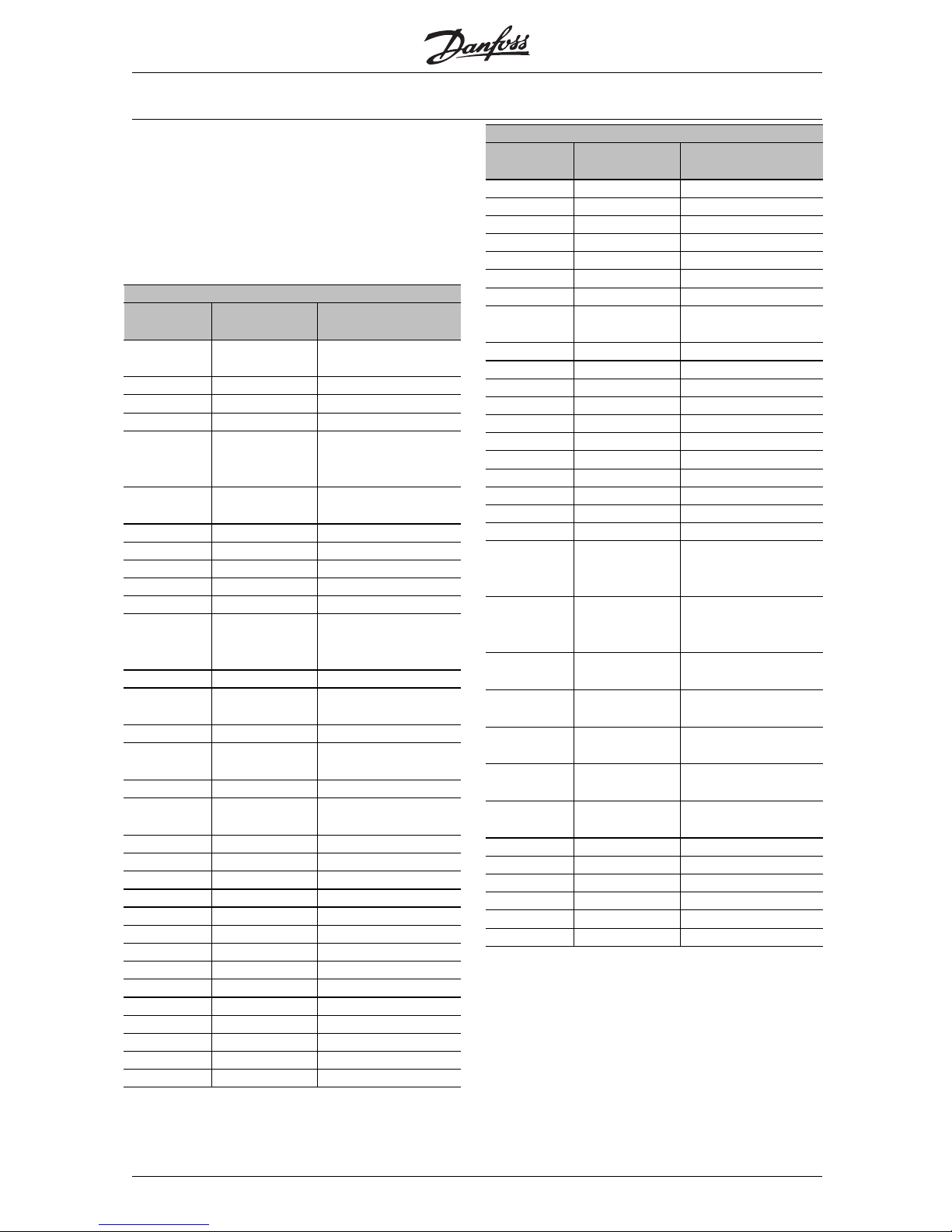
VLT® 5000/ 5000 FLUX/ 6000 HVAC/
8000 AQUA PROFIBUS
■Warning word, extended Status word and
Alarm word
Warning word, extended word and Alarm word are
shownonthedisplayinHexformat.Ifthereismore
than one warning or alarm, a sum of all warnings or
alarms will be shown. Warning word, extended word
and Alarm word can also be displayed using the
serial bus in parameter 540, 541 and 538.
VLT 6000
Bit (Hex) Unit
diagnose bit
Extended word (P.
532)
00000001 80 Overvoltage control
active
00000002 81 Start delay
00000004 82 Sleep boost active
00000008 83 Sleep mode active
00000010 84 Automatic mode
adaptation
completed
00000020 85 Automatic mode
adaptation running
00000040 86 Reversing and start
00000080 87 Ramp operation
00000100 72 Reversing
00000200 73 Speed = reference
00000400 74 Running
00000800 75 Local ref. = 0
Remote controlled
ref. = 1
00001000 76 OFF mode = 1
00002000 77 Auto mode = 0
Hand mode = 1
00004000 78 Start blocked
00008000 79 Start blocked signal
missing
00010000 64 Freeze output
00020000 65 Freeze output
bloced
00040000 66 Jogging
00080000 67 Jog blocked
00100000 68 Stand by
00200000 69 Stop
00400000 70 DC stop
00800000 71 Drive ready
01000000 56 Relay 123 active
02000000 57 Drive ready
04000000 58 Control ready
08000000 59 Start prevented
10000000 60 Profibus OFF3 active
20000000 61 Profibus OFF2 active
40000000 62 Profibus OFF1 active
80000000 63 Reserved
VLT 5000
Bit (Hex) Unit
diagnose bit
Alarm word,
binary (P. 538)
00000001 112 Brake test failed
00000002 113 Trip lock
00000004 114 AMA tuning not OK
00000008 115 AMA tuning OK
00000010 116 Power up fault
00000020 117 ASIC fault
00000040 118 HPFB bus timeout
00000080 119 Standard bus
timeout
00000100 104 Short-circuiting
00000200 105 Switchmode fault
00000400 106 Earth fault
00000800 107 Overcurrent
00001000 108 Torque limit
00002000 109 Motor thermistor
00004000 110 Motor overload
00008000 111 Inverter overload
00010000 96 Undervoltage
00020000 97 Overvoltage
00040000 98 Phase fault
00080000 99 Live zero fault (4-20
mA current signal
low)
00100000 100 Heat sink
temperature too
high
00200000 101 Motor phase W
missing
00400000 102 Motor phase V
missing
00800000 103 Motor phase U
missing
01000000 88 Quick discharge not
OK
02000000 89 Filedbus
communication fault
04000000 90 Mains failure
08000000 91 Inverter fault
10000000 92 Brake power fault
20000000 93 Encoder loss
40000000 94 Safety interlock
80000000 95 Reserved
MG.90.G1.02 - VLT is a registered Danfoss trademark
44
Page 46
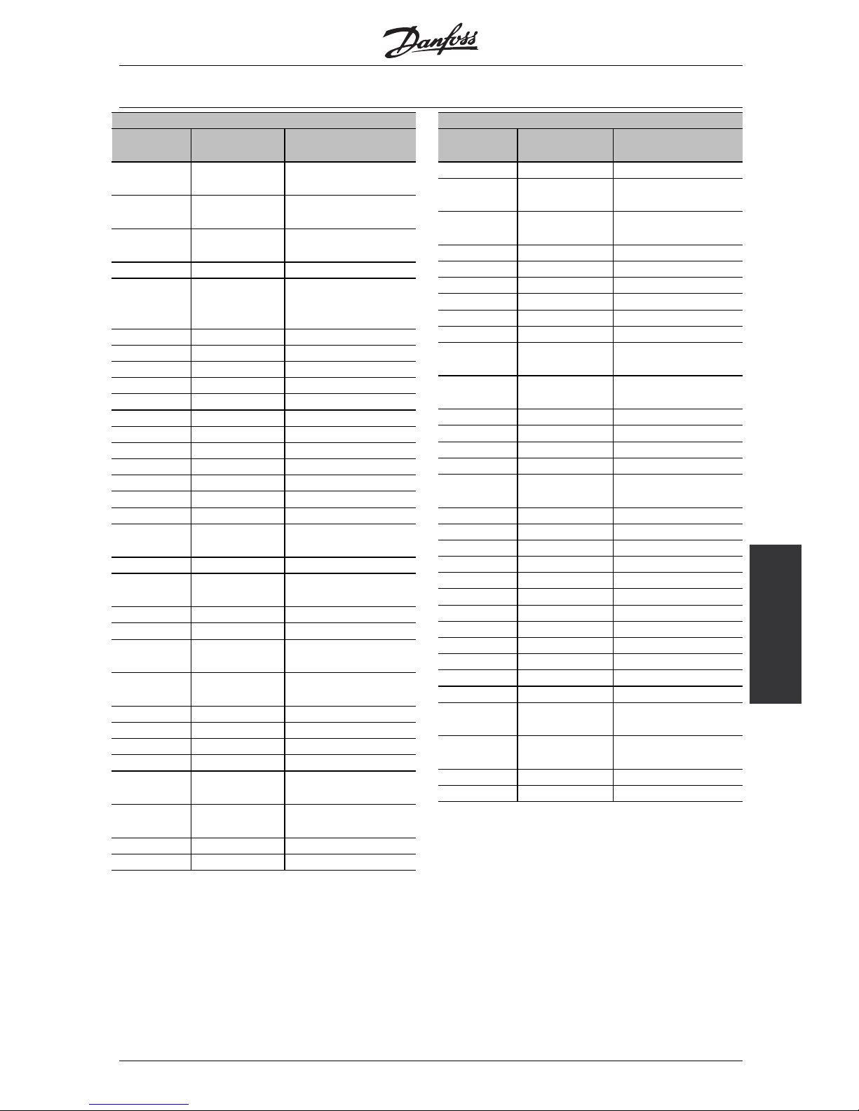
VLT® 5000/ 5000 FLUX/ 6000 HVAC/
8000 AQUA PROFIBUS
Warning and alarm
messages
VLT 5000
Bit (Hex) Unit
diagnose bit
Warning word 1 (P.
540)
00000001 48 Fault during brake
test
00000002 49 Fault in EEprom on
control card
00000004 50 Fault in EEprom on
power card
00000008 51 HPFB bus timeout
00000010 52 Serial
communication
timeout
00000020 53 Overcurrent
00000040 54 Torque limit
00000080 55 Motor thermistor
00000100 40 Motor overload
00000200 41 Inverter overload
00000400 42 Undervoltage
00000800 43 Overvoltage
00001000 44 Voltage warning low
00002000 45 Voltage warning high
00004000 46 Phase fault
00008000 47 No motor
00010000 32 Live zero fault
00020000 33 Under 10 Volt
(terminal 50)
00040000 34 Not used
00080000 35 Brake resistor power
100%
00100000 36 Brake resistor fault
00200000 37 Brake transistor fault
00400000 38 Out of frequency
range
00800000 39 Fieldbus
communication fault
01000000 24 Not used
02000000 25 Mains failure
04000000 26 Motor too small
08000000 27 Motor too big
10000000 28 Check p. 103 and p.
105
20000000 29 Check p. 104 and p.
106
40000000 30 Encoder loss
80000000 31 Not used
VLT 5000
Bit (Hex) Unit
diagnose bit
Extended word (P.
541)
00000001 80 Ramping
00000002 81 Automatic motor
tuning
00000004 82 Start clockwise/anti-
clockwise
00000008 83 Slow down
00000010 84 Catch-up
00000020 85 Feedback high
00000040 86 Feedback low
00000080 87 Output current high
00000100 72 Output current low
00000200 73 Output frequency
high
00000400 74 Output frequency
low
00000800 75 Brake test ok
00001000 76 Braking max.
00002000 77 Braking
00004000 78 Quick discharge OK
00008000 79 Out of frequency
range
00010000 64 Not used
00020000 65 Not used
00040000 66 Not used
00080000 67 Not used
00100000 68 Not used
00200000 69 Not used
00400000 70 Not used
00800000 71 Not used
01000000 56 Not used
02000000 57 Not used
04000000 58 Not used
08000000 59 Not used
10000000 60 PB acyclic MC1
communication
20000000 61 PB acyclic MC2
communication
40000000 62 Not used
80000000 63 Not used
MG.90.G1.02 - VLT is a registered Danfoss trademark
45
Page 47
VLT® 5000/ 5000 FLUX/ 6000 HVAC/
8000 AQUA PROFIBUS
VLT 5000
Bit (Hex) Unit
diagnose bit
Alarm word (P.
953)
00000001 128 Connection with
DP-master is not OK
00000002 129 Not used
00000004 130 FDL is not OK
00000008 131 Clear data
command received
00000010 132 Actual value is not
updated
00000020 133 Spontaneous
message FIFO
overflow
00000040 134 PROFIBUS ASIC is
not transmitting
00000080 135 Initialising of
PROFIBUS is not
OK
00000100 120 Not used
00000200 121 Not used
00000400 122 Not used
00000800 123 Not used
00001000 124 Fatal DPR error
during init: Bit 0
00002000 125 Fatal DPR error
during init: Bit 1
00004000 126 Fatal DPR error
during init: Bit 2
00008000 127 Fatal DPR error
during init: Bit 3
■Station address
The station address of slave can be selected via
- Hardware switch
- Parameter 918 via bus or LCP 2
- Command "Set Station Address" of Profibus DP
The address via the hardware switch is valid, if
the switch is set between 0-125. All selections via
parameter 918 or "Set Station Address" command
will be rejected. The address setting will only be
effective at power up. Changing du ring run time
will be effective at next power up.
The setting of address via parameter 918 is possible,
if the hardware switch is set to 126 or 127 (factory
setting). A new address is effective at a new power up.
The setting of the address via the "Set Station
Address" command is possible, if the hardware
switch is set to 126 or 127 (factory setting). By
the "Set Station Address" command it is possible
to lock the programmed address, which makes it
impossible to change the address by this command.
The address setting will be unlocked, if the parameter
918 or the address switch is changed followed by a
power cycle. A new address is effective immediate
after Set Station Address -command.
MG.90.G1.02 - VLT is a registered Danfoss trademark
46
Page 48

VLT® 5000/ 5000 FLUX/ 6000 HVAC/
8000 AQUA PROFIBUS
Warning and alarm
messages
■Extended Diagnosis
By the extended diagnose function it is possible
to receive alarm and warning information from the
frequency converter. The setting of parameter 849
determines which frequency converter events should
trigger the extended diagnose fun ction.
If parameter 849 is set to Disable [0], no extended
diagnose data is sent regardless wether they
appear in the frequency converter.
If parameter 849 is set to Alarms [1], extended
diagnose data is sent, if one or more alarms arrive
in the Alarm parameters. If parameter 849 is set to
Alarms/Warnings [2], extended diagnose data is sent
if one or more alarms/warnings arrive in the Alarm
parameters or the warning parameter.
The sequence of an extended diagnose is as follows:
If an Alarm or warning appears, the frequency
converter will indicate that to the master by sending
a high prior message via the output data telegram.
This will cause the master to ask the frequency
converter for extended diagnose information, which
will be replied by the frequency converter.
When the Alarm/warning disappears, the frequency
converter will again indicate that to the master, and
on the following request from the master, return a
standard DP diagnose frame (6 bytes).
The extended diagnose frame has the following content:
Byte Content Description
0 through 5 Standard DP Diagnose data Standard DP Diagnose frame
6 Pdu length xx Header of Extended diagnostic data
7 Status type = 0x81 Header of Extended diagnostic data
8 Slot = 0 Header of Extended diagnostic data
9 Status info = 0 Header of Extended diagnostic data
10 through 13 VLT parameter 540 VLT warning word
14 through 17 VLT parameter 541 VLT Status word
18 through 21 VLT parameter 538 VLT Alarm word
22 through 23 VLT parameter 953 Communication warning word
MG.90.G1.02 - VLT is a registered Danfoss trademark
47
Page 49

VLT® 5000/ 5000 FLUX/ 6000 HVAC/
8000 AQUA PROFIBUS
Parameter list VLT 5000
PNU Parameter Factory setting Range Changes 4-Setup Conversion Data
# description during operation index type
001 LLLLaaaannnngggguuuuaaaaggggeeeeEnglish YesNo05
002 LLLLooooccccaaaallll////rrrreeeemmmmooootttteeeeccccoooonnnnttttrrrroooollll R e mote control Yes Yes 0 5
003 LLLLooooccccaaaallllrrrreeeeffffeeeerrrreeeennnncccceeee 000.000 Yes Yes -3 4
004 AAAAccccttttiiiivvvveeeesssseeeettttuuuupppp Setup 1 Yes No 0 5
005 PPPPrrrrooooggggrrrraaaammmmmmmmiiiinnnnggggsssseeeettttuuuupppp Active setup Yes No 0 5
006 CCCCooooppppyyyyiiiinnnnggggooooffffsssseeeettttuuuuppppssss No copying No No 0 5
007 LLLLCCCCPPPPccccooooppppyyyy No copying No No 0 5
008 DDDDiiiissssppppllllaaaayyyyssssccccaaaalllliiiinnnnggggooooffffmmmmoooottttoooorrrrffffrrrreeeeqqqquuuueeeennnnccccyyyy 1 0.01 - 500.00 Yes Yes -2 6
009 DDDDiiiissssppppllllaaaayyyylllliiiinnnneeee2222 Frequency [Hz] Yes Yes 0 5
010 DDDDiiiissssppppllllaaaayyyylllliiiinnnneeee1111....1111 Reference [%] Yes Yes 0 5
011 DDDDiiiissssppppllllaaaayyyylllliiiinnnneeee1111....2222 Motor current [A] Yes Yes 0 5
012 DDDDiiiissssppppllllaaaayyyylllliiiinnnneeee1111....3333 Power [kW] Yes Yes 0 5
013 LLLLooooccccaaaallllccccoooonnnnttttrrrroooollll////ccccoooonnnnffffiiiigggguuuurrrraaaa LCP digital control/as
par.100
Yes Yes 0 5
014 LLLLooooccccaaaallllssssttttoooopppp Possible Yes Yes 0 5
015 LLLLooooccccaaaalllljjjjoooogggg Not possible Yes Yes 0 5
016 LLLLooooccccaaaallllrrrreeeevvvveeeerrrrssssiiiinnnngggg Not possible Yes Yes 0 5
017 LLLLooooccccaaaallllrrrreeeesssseeeettttooooffffttttrrrriiiipppp Possible Yes Yes 0 5
018 LLLLoooocccckkkkffffoooorrrrddddaaaattttaaaacccchhhhaaaannnnggggeeee Not locked Yes Yes 0 5
019 OOOOppppeeeerrrraaaattttiiiinnnnggggssssttttaaaatttteeeeaaaattttppppoooowwwweeeerrrr----uuuupppp,,,,llllooooccccaaaallll
ccccoooonnnnttttrrrroooollll
Forced stop, use
saved ref.
Yes Yes 0 5
027 WWWWaaaarrrrnnnniiiinnnnggggrrrreeeeaaaaddddoooouuuutttt Warning in line 1/2 Yes No 0 5
Changes during operation:
"Yes" means that the parameter can be changed,
while the frequency converter is in operation. "No"
means that the frequency converter must be stopped
before a change can be made.
4
-Setup:
"Yes" means that the parameter can be programmed
individually in each of the four setups, i.e. the
same parameter can have four different data
values. "No" means that the data value will be
the same in all four setups.
C
onversion index:
This number refers to a conversi
on figure to
be used when writing or reading by means
of a frequency converter.
Conversion index Conver sion fa cto r
74 0.1
2100
110
01
-1 0.1
-2 0.01
-3 0.001
-4 0.0001
Data type:
Data type showsthe type and length of the telegram.
Data type Description
3 Integer 16
4 Integer 32
5Unsigned8
6Unsigned16
7Unsigned32
9Textstring
MG.90.G1.02 - VLT is a registered Danfoss trademark
48
Page 50

VLT® 5000/ 5000 FLUX/ 6000 HVAC/
8000 AQUA PROFIBUS
Parameter
list
PNU Parameter Factory setting Range Changes 4-Setup Conversion Data
# description during operation index type
100 CCCCoooonnnnffffiiiigggguuuurrrraaaattttiiiioooonnnn Speed control, open loop No Yes 0 5
101 TTTToooorrrrqqqquuuueeeecccchhhhaaaarrrraaaacccctttteeeerrrriiiissssttttiiiiccccssss High - constant torque Yes Yes 0 5
102 MMMMoooottttoooorrrrppppoooowwwweeeerrrr Depends on the unit 0.18-600 kW No Yes 1 6
103 MMMMoooottttoooorrrrvvvvoooollllttttaaaaggggeeee Depends on the unit 200 - 600 V No Yes 0 6
104 MMMMoooottttoooorrrrffffrrrreeeeqqqquuuueeeennnnccccyyyy 50 Hz / 60 Hz No Yes 0 6
105 MMMMoooottttoooorrrrccccuuuurrrrrrrreeeennnntttt Depends o n the unit 0.01-I
VLT,MAX
No Yes -2 7
106 RRRRaaaatttteeeeddddmmmmoooottttoooorrrrssssppppeeeeeeeedddd Depends on the unit 100-60000 rpm No Yes 0 6
107 AAAAuuuuttttoooommmmaaaattttiiiiccccmmmmoooottttoooorrrraaaaddddaaaappppttttaaaattttiiiioooonnnn,,,,AAAAMMMMAAAA Adaptation off No No 0 5
108 SSSSttttaaaattttoooorrrrrrrreeeessssiiiissssttttoooorrrr Depends on the unit No Yes -4 7
109 SSSSttttaaaattttoooorrrrrrrreeeeaaaaccccttttaaaannnncccceeee Depends on the unit No Yes -2 7
110 MMMMoooottttoooorrrrmmmmaaaaggggnnnneeeettttiiiizzzziiiinnnngggg,,,,0000rrrrppppmmmm 100 % 0 - 300 % Yes Yes 0 6
111 MMMMiiiinnnn....ffffrrrreeeeqqqquuuueeeennnnccccyyyynnnnoooorrrrmmmmaaaallll
mmmmaaaaggggnnnneeeettttiiiizzzziiiinnnngggg
1.0 Hz 0.1 - 10.0 Hz Yes Yes -1 6
112
113 LLLLooooaaaaddddccccoooommmmppppeeeennnnssssaaaattttiiiioooonnnnaaaattttlllloooowwwwssssppppeeeeeeeedddd 100 % 0 - 300 % Yes Yes 0 6
114 LLLLooooaaaaddddccccoooommmmppppeeeennnnssssaaaattttiiiioooonnnnaaaatttthhhhiiiigggghhhhssssppppeeeeeeeedddd 100 % 0 - 300 % Yes Yes 0 6
115 SSSSlllliiiippppccccoooommmmppppeeeennnnssssaaaattttiiiioooonnnn 100 % -500 - 500 % Yes Yes 0 3
116 SSSSlllliiiippppccccoooommmmppppeeeennnnssssaaaattttiiiioooonnnnttttiiiimmmmeeeeccccoooonnnnssssttttaaaannnntttt 0.50 s 0.05 - 1.00 s Yes Yes -2 6
117 RRRReeeessssoooonnnnaaaannnncccceeeeddddaaaammmmppppeeeennnniiiinnnngggg 100 % 0 - 500 % Yes Yes 0 6
118 RRRReeeessssoooonnnnaaaannnncccceeeeddddaaaammmmppppeeeennnniiiinnnnggggttttiiiimmmmeeee
ccccoooonnnnssssttttaaaannnntttt
5ms 5-50ms Yes Yes -3 6
119 HHHHiiiigggghhhhssssttttaaaarrrrttttiiiinnnnggggttttoooorrrrqqqquuuueeee 0.0 sec. 0.0 - 0.5 s Yes Yes -1 5
120 SSSSttttaaaarrrrttttddddeeeellllaaaayyyy 0.0 sec. 0.0 - 10.0 s Yes Yes -1 5
121 SSSSttttaaaarrrrttttffffuuuunnnnccccttttiiiioooonnnn Coasting in start delay time Yes Yes 0 5
122 FFFFuuuunnnnccccttttiiiioooonnnnaaaattttssssttttooooppppCoasting YesYes05
123 MMMMiiiinnnn....ffffrrrreeeeqqqquuuueeeennnnccccyyyyffffoooorrrraaaaccccttttiiiivvvvaaaattttiiiinnnngggg
ffffuuuunnnnccccttttiiiioooonnnnaaaattttssssttttoooopppp
0.0 Hz 0.0 - 10.0 Hz Yes Yes -1 5
124 DDDDCCCChhhhoooollllddddiiiinnnnggggccccuuuurrrrrrrreeeennnntttt 50% 0-100% Yes Yes 0 6
125 DDDDCCCCbbbbrrrraaaakkkkiiiinnnnggggccccuuuurrrrrrrreeeennnntttt 50% 0-100% Yes Yes 0 6
126 DDDDCCCCbbbbrrrraaaakkkkiiiinnnnggggttttiiiimmmmeeee 10.0 sec. 0.0 - 60.0 sec. Yes Yes -1 6
127 DDDDCCCCbbbbrrrraaaakkkkeeeeccccuuuutttt----iiiinnnnffffrrrreeeeqqqquuuueeeennnnccccyyyy Off 0.0-par. 202 Yes Yes -1 6
128 MMMMoooottttoooorrrrtttthhhheeeerrrrmmmmaaaallllpppprrrrooootttteeeeccccttttiiiioooonnnnNoprotection YesYes0 5
129 EEEExxxxtttteeeerrrrnnnnaaaallllmmmmoooottttoooorrrrffffaaaannnnNo YesYes05
130 SSSSttttaaaarrrrttttffffrrrreeeeqqqquuuueeeennnnccccyyyy 0.0 Hz 0.0-10.0 Hz Yes Yes -1 5
131 IIIInnnniiiittttiiiiaaaallllvvvvoooollllttttaaaaggggeeee 0.0 V 0.0-par. 103 Yes Yes -1 6
145 MMMMiiiinnnniiiimmmmuuuummmmDDDDCCCCbbbbrrrraaaakkkkeeeettttiiiimmmmeeee 0 sec. 0 - 10 sec. Yes Yes -1 6
MG.90.G1.02 - VLT is a registered Danfoss trademark
49
Page 51

VLT® 5000/ 5000 FLUX/ 6000 HVAC/
8000 AQUA PROFIBUS
PNU Parameter Factory setting Range Changes 4-Setup Conversion Data
# description during operation index type
200 OOOOuuuuttttppppuuuuttttffffrrrreeeeqqqquuuueeeennnnccccyyyy
rrrraaaannnnggggeeee////ddddiiiirrrreeeeccccttttiiiioooonnnn
Only clockwise, 0-132 Hz No Yes 0 5
201 OOOOuuuuttttppppuuuuttttffffrrrreeeeqqqquuuueeeennnnccccyyyylllloooowwwwlllliiiimmmmiiiitttt0.0Hz 0.0-f
MAX
Yes Yes -1 6
202 OOOOuuuuttttppppuuuuttttffffrrrreeeeqqqquuuueeeennnnccccyyyyhhhhiiiigggghhhhlllliiiimmmmiiiitttt66/132Hz f
MIN
- par. 200 Yes Yes -1 6
203 RRRReeeeffffeeeerrrreeeennnncccceeee////ffffeeeeeeeeddddbbbbaaaacccckkkkaaaarrrreeeeaaaa Min - max Yes Yes 0 5
204 MMMMiiiinnnniiiimmmmuuuummmmrrrreeeeffffeeeerrrreeeennnncccceeee 0.000 -100,000.000-Ref
MAX
Yes Yes -3 4
205 MMMMaaaaxxxxiiiimmmmuuuummmmrrrreeeeffffeeeerrrreeeennnncccceeee 50.000 Ref
MIN
-100,000.000 Yes Yes -3 4
206 RRRRaaaammmmppppttttyyyyppppeeeeLinear YesYes05
207 RRRRaaaammmmpppp----uuuuppppttttiiiimmmmeeee1111 Depends on unit 0.05 - 3600 Yes Yes -2 7
208 RRRRaaaammmmpppp----ddddoooowwwwnnnnttttiiiimmmmeeee1111 Depends on unit 0.05 - 3600 Yes Yes -2 7
209 RRRRaaaammmmpppp----uuuuppppttttiiiimmmmeeee2222 Depends on unit 0.05 - 3600 Yes Yes -2 7
210 RRRRaaaammmmpppp----ddddoooowwwwnnnnttttiiiimmmmeeee2222 Depends on unit 0.05 - 3600 Yes Yes -2 7
211 JJJJooooggggrrrraaaammmmppppttttiiiimmmmeeee Depends on unit 0.05 - 3600 Yes Yes -2 7
212 QQQQuuuuiiiicccckkkkssssttttoooopppprrrraaaammmmpppp----ddddoooowwwwnnnnttttiiiimmmmeeee Depends on unit 0.05 - 36 00 Yes Yes -2 7
213 JJJJooooggggffffrrrreeeeqqqquuuueeeennnnccccyyyy 10.0 Hz 0.0 - par. 202 Yes Yes -1 6
214 RRRReeeeffffeeeerrrreeeennnncccceeeeffffuuuunnnnccccttttiiiioooonnnnSum YesYes05
215 PPPPrrrreeeesssseeeettttrrrreeeeffffeeeerrrreeeennnncccceeee1111 0.00 % - 100.00 - 100.00 % Yes Yes -2 3
216 PPPPrrrreeeesssseeeettttrrrreeeeffffeeeerrrreeeennnncccceeee2222 0.00 % - 100.00 - 100.00 % Yes Yes -2 3
217 PPPPrrrreeeesssseeeettttrrrreeeeffffeeeerrrreeeennnncccceeee3333 0.00 % - 100.00 - 100.00 % Yes Yes -2 3
218 PPPPrrrreeeesssseeeettttrrrreeeeffffeeeerrrreeeennnncccceeee4444 0.00 % - 100.00 - 100.00 % Yes Yes -2 3
219 CCCCaaaattttcccchhhhuuuupppp////sssslllloooowwwwddddoooowwwwnnnnvvvvaaaalllluuuueeee 0.00 % 0.00 - 100 % Ye s Yes -2 6
220
221 TTTToooorrrrqqqquuuueeeelllliiiimmmmiiiittttffffoooorrrrmmmmoooottttoooorrrrmmmmooooddddeeee 160 % 0.0 % - xxx % Yes Yes -1 6
222 TTTToooorrrrqqqquuuueeeelllliiiimmmmiiiittttffffoooorrrrrrrreeeeggggeeeennnneeeerrrraaaattttiiiivvvveeee
ooooppppeeeerrrraaaattttiiiioooonnnn
160 % 0.0 % - xxx % Yes Yes -1 6
223 WWWWaaaarrrrnnnniiiinnnngggg::::LLLLoooowwwwccccuuuurrrrrrrreeeennnntttt 0.0 A 0.0 - par. 224 Yes Yes -1 6
224 WWWWaaaarrrrnnnniiiinnnngggg::::HHHHiiiigggghhhhccccuuuurrrrrrrreeeennnnttttI
VLT,MAX
Par. 223 - I
VLT,MAX
Yes Yes -1 6
225 WWWWaaaarrrrnnnniiiinnnngggg::::LLLLoooowwwwffffrrrreeeeqqqquuuueeeennnnccccyyyy 0.0 Hz 0.0 - par. 226 Yes Yes -1 6
226 WWWWaaaarrrrnnnniiiinnnngggg::::HHHHiiiigggghhhhffffrrrreeeeqqqquuuueeeennnnccccyyyy 132.0 Hz Par. 225 - par. 202 Yes Yes -1 6
227 WWWWaaaarrrrnnnniiiinnnngggg::::LLLLoooowwwwffffeeeeeeeeddddbbbbaaaacccckkkk -4000.000 -100,000.000 - par. 228 Yes -3 4
228 WWWWaaaarrrrnnnniiiinnnngggg::::HHHHiiiigggghhhhffffeeeeeeeeddddbbbbaaaacccckkkk 4000.000 Par. 227 - 100,000.000 Yes -3 4
229 FFFFrrrreeeeqqqquuuueeeennnnccccyyyybbbbyyyyppppaaaassssssss,,,,bbbbaaaannnnddddwwwwiiiiddddtttthhhh OFF 0 - 100 % Yes Yes 0 6
230 FFFFrrrreeeeqqqquuuueeeennnnccccyyyybbbbyyyyppppaaaassssssss1111 0.0 Hz 0.0 - par. 200 Yes Yes -1 6
231 FFFFrrrreeeeqqqquuuueeeennnnccccyyyybbbbyyyyppppaaaassssssss2222 0.0 Hz 0.0 - par. 200 Yes Yes -1 6
232 FFFFrrrreeeeqqqquuuueeeennnnccccyyyybbbbyyyyppppaaaassssssss3333 0.0 Hz 0.0 - par. 200 Yes Yes -1 6
233 FFFFrrrreeeeqqqquuuueeeennnnccccyyyybbbbyyyyppppaaaassssssss4444 0.0 Hz 0.0 - par. 200 Yes Yes -1 6
234 MMMMoooottttoooorrrrpppphhhhaaaasssseeeemmmmoooonnnniiiittttoooorrrrEnable YesYes05
MG.90.G1.02 - VLT is a registered Danfoss trademark
50
Page 52

VLT® 5000/ 5000 FLUX/ 6000 HVAC/
8000 AQUA PROFIBUS
Parameter
list
PNU Parameter Factory setting Range Changes 4-Setup Conversion Data
# description during operation index type
300 TTTTeeeerrrrmmmmiiiinnnnaaaallll11116666,,,,iiiinnnnppppuuuutttt Reset Yes Yes 0 5
301 TTTTeeeerrrrmmmmiiiinnnnaaaallll11117777,,,,iiiinnnnppppuuuutttt Freeze reference Yes Yes 0 5
302 TTTTeeeerrrrmmmmiiiinnnnaaaallll11118888SSSSttttaaaarrrrtttt,,,,iiiinnnnppppuuuuttttStart YesYes05
303 TTTTeeeerrrrmmmmiiiinnnnaaaallll11119999,,,,iiiinnnnppppuuuutttt Reversing Yes Yes 0 5
304 TTTTeeeerrrrmmmmiiiinnnnaaaallll22227777,,,,iiiinnnnppppuuuutttt Coasting stop, inverse Yes Yes 0 5
305 TTTTeeeerrrrmmmmiiiinnnnaaaallll22229999,,,,iiiinnnnppppuuuuttttJog YesYes05
306 TTTTeeeerrrrmmmmiiiinnnnaaaallll33332222,,,,iiiinnnnppppuuuutttt Choice of setup, msb/speed up Yes Yes 0 5
307 TTTTeeeerrrrmmmmiiiinnnnaaaallll33333333,,,,iiiinnnnppppuuuutttt Choice of setup, lsb/speed down Yes Yes 0 5
308 TTTTeeeerrrrmmmmiiiinnnnaaaallll55553333,,,,aaaannnnaaaalllloooogggguuuueeeeiiiinnnnppppuuuuttttvvvvoooollllttttaaaaggggeeee Reference Yes Yes 0 5
309 TTTTeeeerrrrmmmmiiiinnnnaaaallll55553333,,,,mmmmiiiinnnn....ssssccccaaaalllliiiinnnngggg 0.0 V 0.0 - 10.0 V Ye s Yes -1 5
310 TTTTeeeerrrrmmmmiiiinnnnaaaallll55553333,,,,mmmmaaaaxxxx....ssssccccaaaalllliiiinnnngggg 10.0 V 0.0 - 10.0 V Yes Yes -1 5
311 TTTTeeeerrrrmmmmiiiinnnnaaaallll55554444,,,,aaaannnnaaaalllloooogggguuuueeeeiiiinnnnppppuuuuttttvvvvoooollllttttaaaaggggeeeeNooperation Yes Yes 0 5
312 TTTTeeeerrrrmmmmiiiinnnnaaaallll55554444,,,,mmmmiiiinnnn....ssssccccaaaalllliiiinnnngggg 0.0 V 0.0 - 10.0 V Ye s Yes -1 5
313 TTTTeeeerrrrmmmmiiiinnnnaaaallll55554444,,,,mmmmaaaaxxxx....ssssccccaaaalllliiiinnnngggg 10.0 V 0.0 - 10.0 V Yes Yes -1 5
314 TTTTeeeerrrrmmmmiiiinnnnaaaallll66660000,,,,aaaannnnaaaalllloooogggguuuueeeeiiiinnnnppppuuuuttttccccuuuurrrrrrrreeeennnntttt Reference Yes Yes 0 5
315 TTTTeeeerrrrmmmmiiiinnnnaaaallll66660000,,,,mmmmiiiinnnn....ssssccccaaaalllliiiinnnngggg 0.0 mA 0.0 - 20.0 mA Yes Yes -4 5
316 TTTTeeeerrrrmmmmiiiinnnnaaaallll66660000,,,,mmmmaaaaxxxx....ssssccccaaaalllliiiinnnngggg 20.0 mA 0.0 - 20.0 mA Yes Yes -4 5
317 TTTTiiiimmmmeeeeoooouuuutttt 10 sec. 1 - 99 sec. Yes Yes 0 5
318 FFFFuuuunnnnccccttttiiiioooonnnnaaaafffftttteeeerrrrttttiiiimmmmeeeeoooouuuuttttOff YesYes05
319 0 - I
MAX
Þ0-20mA Yes Yes 0 5
320 TTTTeeeerrrrmmmmiiiinnnnaaaallll44442222,,,,oooouuuuttttppppuuuutttt,,,,ppppuuuullllsssseeeessssccccaaaalllliiiinnnngggg 5000 Hz 1 - 32000 Hz Yes Yes 0 6
321 TTTTeeeerrrrmmmmiiiinnnnaaaallll44445555,,,,oooouuuuttttppppuuuutttt0-f
MAX
Þ0-20mA Yes Yes 0 5
322 TTTTeeeerrrrmmmmiiiinnnnaaaallll44445555,,,,oooouuuuttttppppuuuutttt,,,,ppppuuuullllsssseeeessssccccaaaalllliiiinnnngggg 5000 Hz 1 - 32000 Hz Yes Yes 0 6
323 RRRReeeellllaaaayyyy00001111,,,,oooouuuuttttppppuuuutttt R eady - no thermal warning Yes Yes 0 5
324 RRRReeeellllaaaayyyy00001111,,,,OOOONNNNddddeeeellllaaaayyyy 0.00 sec. 0.00 - 600 sec. Yes Yes -2 6
325 RRRReeeellllaaaayyyy00001111,,,,OOOOFFFFFFFFddddeeeellllaaaayyyy 0.00 sec. 0.00 - 600 sec. Yes Yes -2 6
326 RRRReeeellllaaaayyyy00004444,,,,oooouuuuttttppppuuuutttt Ready - remote control Yes Yes 0 5
327 PPPPuuuullllsssseeeerrrreeeeffffeeeerrrreeeennnncccceeee,,,,mmmmaaaaxxxx....ffffrrrreeeeqqqquuuueeeennnnccccyyyy 5000 Hz Yes Yes 0 6
328 PPPPuuuullllsssseeeeffffeeeeeeeeddddbbbbaaaacccckkkk,,,,mmmmaaaaxxxx....ffffrrrreeeeqqqquuuueeeennnnccccyyyy 25000 Hz Yes Yes 0 6
329 EEEEnnnnccccooooddddeeeerrrrffffeeeeeeeeddddbbbbaaaacccckkkkppppuuuullllsssseeee////rrrreeeevvvv.... 1024 pulses/rev. 1 - 4096
pulses/rev.
Yes Yes 0 6
330 FFFFrrrreeeeeeeezzzzeeeerrrreeeeffffeeeerrrreeeennnncccceeee////oooouuuuttttppppuuuuttttffffuuuunnnnccccttttiiiioooonnnnNooperation YesNo 0 5
345 EEEEnnnnccccooooddddeeeerrrrlllloooossssssssttttiiiimmmmeeeeoooouuuutttt 1 sec. 0 - 60 sec Yes Yes -1 6
346 EEEEnnnnccccooooddddeeeerrrrlllloooossssssssffffuuuunnnnccccttttiiiioooonnnnOFF YesYes05
357 TTTTeeeerrrrmmmmiiiinnnnaaaallll44442222,,,,OOOOuuuuttttppppuuuuttttmmmmiiiinnnniiiimmmmuuuummmm
ssssccccaaaalllliiiinnnngggg
0 % 000 - 100% Yes Yes 0 6
358 TTTTeeeerrrrmmmmiiiinnnnaaaallll44442222,,,,OOOOuuuuttttppppuuuuttttmmmmaaaaxxxxiiiimmmmuuuummmm
ssssccccaaaalllliiiinnnngggg
100% 000 - 500% Yes Yes 0 6
359 TTTTeeeerrrrmmmmiiiinnnnaaaallll44445555,,,,OOOOuuuuttttppppuuuuttttmmmmiiiinnnniiiimmmmuuuummmm
ssssccccaaaalllliiiinnnngggg
0 % 000 - 100% Yes Yes 0 6
360 TTTTeeeerrrrmmmmiiiinnnnaaaallll44445555,,,,OOOOuuuuttttppppuuuuttttmmmmaaaaxxxxiiiimmmmuuuummmm
ssssccccaaaalllliiiinnnngggg
100% 000 - 500% Yes Yes 0 6
361 EEEEnnnnccccooooddddeeeerrrrlllloooosssssssstttthhhhrrrreeeesssshhhhoooolllldddd 300% 000 - 600 % Yes Yes 0 6
MG.90.G1.02 - VLT is a registered Danfoss trademark
51
Page 53

VLT® 5000/ 5000 FLUX/ 6000 HVAC/
8000 AQUA PROFIBUS
PNU Parameter Factory setting Range Changes 4-Setup Conversion Data
# description during operation index type
400 BBBBrrrraaaakkkkeeeeffffuuuunnnnccccttttiiiioooonnnn////oooovvvveeeerrrrvvvvoooollllttttaaaaggggeeeeccccoooonnnnttttrrrroooollllOff YesNo0 5
401 BBBBrrrraaaakkkkeeeerrrreeeessssiiiissssttttoooorrrr,,,,oooohhhhmmmm Depends on the unit Yes No -1 6
402 BBBBrrrraaaakkkkeeeeppppoooowwwweeeerrrrlllliiiimmmmiiiitttt,,,,kkkkWWWW Depends on the unit Yes No 2 6
403 PPPPoooowwwweeeerrrrmmmmoooonnnniiiittttoooorrrriiiinnnnggggOn YesNo05
404 BBBBrrrraaaakkkkeeeecccchhhheeeecccckkkkOff YesNo05
405 RRRReeeesssseeeettttffffuuuunnnnccccttttiiiioooonnnn Manual reset Yes Yes 0 5
406 AAAAuuuuttttoooommmmaaaattttiiiiccccrrrreeeessssttttaaaarrrrttttttttiiiimmmmeeee 5 sec. 0 - 10 sec. Yes Yes 0 5
407 MMMMaaaaiiiinnnnssssFFFFaaaaiiiilllluuuurrrreeee No function Yes Yes 0 5
408 QQQQuuuuiiiicccckkkkddddiiiisssscccchhhhaaaarrrrggggeeee Not possible Yes Yes 0 5
409 TTTTrrrriiiippppddddeeeellllaaaayyyyttttoooorrrrqqqquuuueeee Off 0 - 60 sec. Yes Yes 0 5
410 TTTTrrrriiiippppddddeeeellllaaaayyyy----iiiinnnnvvvveeeerrrrtttteeeerrrr Depends on type of unit 0 - 35 sec. Yes Yes 0 5
411 SSSSwwwwiiiittttcccchhhhiiiinnnnggggffffrrrreeeeqqqquuuueeeennnnccccyyyy Depends on type of unit 3 - 14 kHz Yes Yes 2 6
412 OOOOuuuuttttppppuuuuttttffffrrrreeeeqqqquuuueeeennnnccccyyyyddddeeeeppppeeeennnnddddeeeennnnttttsssswwwwiiiittttcccchhhhiiiinnnngggg
ffffrrrreeeeqqqquuuueeeennnnccccyyyy
Not possible Yes Yes 0 5
413 OOOOvvvveeeerrrrmmmmoooodddduuuullllaaaattttiiiioooonnnnffffuuuunnnnccccttttiiiioooonnnnOn YesYes-15
414 MMMMiiiinnnniiiimmmmuuuummmmffffeeeeeeeeddddbbbbaaaacccckkkk 0.000 -100,000.000
-FB
HIGH
Yes Yes -3 4
415 MMMMaaaaxxxxiiiimmmmuuuummmmffffeeeeeeeeddddbbbbaaaacccckkkk 1500.000 FB
LOW
-
100,000.000
Yes Yes -3 4
416 PPPPrrrroooocccceeeessssssssuuuunnnniiiitttt% YesYes05
417 SSSSppppeeeeeeeeddddPPPPIIIIDDDDpppprrrrooooppppoooorrrrttttiiiioooonnnnaaaallllggggaaaaiiiinnnn 0.015 0.000 - 0.150 Yes Yes -3 6
418 SSSSppppeeeeeeeeddddPPPPIIIIDDDDiiiinnnntttteeeeggggrrrraaaattttiiiioooonnnnttttiiiimmmmeeee 8 ms 2.00 - 999.99msYes Yes -4 7
419 SSSSppppeeeeeeeeddddPPPPIIIIDDDDddddiiiiffffffffeeeerrrreeeennnnttttiiiiaaaattttiiiioooonnnnttttiiiimmmmeeee 30 ms 0.00 - 200.00msYes Yes -4 6
420 SSSSppppeeeeeeeeddddPPPPIIIIDDDDddddiiiiffffffff....ggggaaaaiiiinnnnrrrraaaattttiiiioooo 5.0 5.0 - 50.0 Yes Yes -1 6
421 SSSSppppeeeeeeeeddddPPPPIIIIDDDDlllloooowwww----ppppaaaassssssssffffiiiilllltttteeeerrrr 10 ms 5 - 200 ms Yes Yes -4 6
422 UUUU0000vvvvoooollllttttaaaaggggeeeeaaaatttt0000HHHHzzzz 20.0 V 0.0 -
parameter
103
Yes Yes -1 6
423 UUUU1111vvvvoooollllttttaaaaggggeeee parameter 103 0.0 - U
VLT, MAX
Yes Yes -1 6
424 FFFF1111ffffrrrreeeeqqqquuuueeeennnnccccyyyy parameter 104 0.0 -
parameter
426
Yes Yes -1 6
425 UUUU2222vvvvoooollllttttaaaaggggeeee parameter 103 0.0 - U
VLT, MAX
Yes Yes -1 6
426 FFFF2222ffffrrrreeeeqqqquuuueeeennnnccccyyyy parameter 104 par.424-
par. 428
Yes Yes -1 6
427 UUUU3333vvvvoooollllttttaaaaggggeeee parameter 103 0.0 - U
VLT, MAX
Yes Yes -1 6
428 FFFF3333ffffrrrreeeeqqqquuuueeeennnnccccyyyy parameter 104 par.426
-par.430
Yes Yes -1 6
429 UUUU4444vvvvoooollllttttaaaaggggeeee parameter 103 0.0 - U
VLT, MAX
Yes Yes -1 6
MG.90.G1.02 - VLT is a registered Danfoss trademark
52
Page 54

VLT® 5000/ 5000 FLUX/ 6000 HVAC/
8000 AQUA PROFIBUS
Parameter
list
PNU Parameter Factory setting Range Changes 4-Setup Conversion Data
# description during operation index type
430 FFFF4444ffffrrrreeeeqqqquuuueeeennnnccccyyyy parameter 104 par.426-par.432 Yes Yes -1 6
431 UUUU5555vvvvoooollllttttaaaaggggeeee parameter 103 .0 - U
VLT, MAX
Yes Yes -1 6
432 FFFF5555ffffrrrreeeeqqqquuuueeeennnnccccyyyy parameter 104 par.426 - 1000 Hz Yes Yes -1 6
433 TTTToooorrrrqqqquuuueeeepppprrrrooooppppoooorrrrttttiiiioooonnnnaaaallllggggaaaaiiiinnnn 100% 0 (Off) - 500% Yes Yes 0 6
434 TTTToooorrrrqqqquuuueeeeiiiinnnntttteeeeggggrrrraaaallllttttiiiimmmmeeee 0.02 sec. 0.002 - 2.000 sec. Yes Yes -3 7
437 PPPPrrrroooocccceeeessssssssPPPPIIIIDDDDNNNNoooorrrrmmmmaaaallll////iiiinnnnvvvveeeerrrrsssseeeeccccoooonnnnttttrrrroooollllNormal YesYes0 5
438 PPPPrrrroooocccceeeessssssssPPPPIIIIDDDDaaaannnnttttiiiiwwwwiiiinnnndddduuuuppppOn YesYes05
439 PPPPrrrroooocccceeeessssssssPPPPIIIIDDDDssssttttaaaarrrrttttffffrrrreeeeqqqquuuueeeennnnccccyyyy parameter 201 f
min - fmax
Yes Yes -1 6
440 PPPPrrrroooocccceeeessssssssPPPPIIIIDDDDpppprrrrooooppppoooorrrrttttiiiioooonnnnaaaallllggggaaaaiiiinnnn 0.01 0.00 - 10.00 Yes Yes -2 6
441 PPPPrrrroooocccceeeessssssssPPPPIIIIDDDDiiiinnnntttteeeeggggrrrraaaallllttttiiiimmmmeeee 9999.99 sec. (OFF) 0.01 - 9999.99 sec. Yes Yes -2 7
442 PPPPrrrroooocccceeeessssssssPPPPIIIIDDDDddddiiiiffffffffeeeerrrreeeennnnttttiiiiaaaattttiiiioooonnnnttttiiiimmmmeeee 0.00 sec. (OFF) 0.00 - 10.00 sec. Yes Yes -2 6
443 PPPPrrrroooocccceeeessssssssPPPPIIIIDDDDddddiiiiffffffff....ggggaaaaiiiinnnnlllliiiimmmmiiiitttt 5.0 5.0 - 50.0 Yes Yes -1 6
444 PPPPrrrroooocccceeeessssssssPPPPIIIIDDDDlllloooowwwwppppaaaassssssssffffiiiilllltttteeeerrrrttttiiiimmmmeeee 0.01 0.01 - 10.00 Yes Yes -2 6
445 FFFFllllyyyyiiiinnnnggggssssttttaaaarrrrtttt Disable Yes Yes 0 5
446 SSSSwwwwiiiittttcccchhhhiiiinnnnggggppppaaaatttttttteeeerrrrnnnnSFAVM YesYes05
447 TTTToooorrrrqqqquuuueeeeccccoooommmmppppeeeennnnssssaaaattttiiiioooonnnn 100% -100 - +100% Yes Yes 0 3
448 GGGGeeeeaaaarrrrrrrraaaattttiiiioooo 1 0.001 - 100.000 No Yes -2 4
449 FFFFrrrriiiiccccttttiiiioooonnnnlllloooossssssss 0% 0 - 50% No Yes -2 6
450 MMMMaaaaiiiinnnnssssvvvvoooollllttttaaaaggggeeeeaaaattttmmmmaaaaiiiinnnnssssffffaaaauuuulllltttt Depends on unit Depends on unit Yes Yes 0 6
453 SSSSppppeeeeeeeeddddcccclllloooosssseeeeddddllllooooooooppppggggeeeeaaaarrrrrrrraaaattttiiiioooo 1 0.01-100 No Yes 0 4
454 DDDDeeeeaaaaddddttttiiiimmmmeeeeccccoooommmmppppeeeennnnssssaaaattttiiiioooonnnnOn NoNo05
455 FFFFrrrreeeeqqqquuuueeeennnnccccyyyyrrrraaaannnnggggeeeemmmmoooonnnniiiittttoooorrrrEnable 05
457 PPPPhhhhaaaasssseeeelllloooossssssssffffuuuunnnnccccttttiiiioooonnnnTrip YesYes05
483 DDDDyyyynnnnaaaammmmiiiiccccDDDDCCCCLLLLiiiinnnnkkkkccccoooommmmppppeeeennnnssssaaaattttiiiioooonnnnOn NoNo0 5
MG.90.G1.02 - VLT is a registered Danfoss trademark
53
Page 55

VLT® 5000/ 5000 FLUX/ 6000 HVAC/
8000 AQUA PROFIBUS
PNU Parameter Factory setting Range Changes 4-Setup Conversion Data
# description during operation index type
500 AAAAddddddddrrrreeeessssssss10-126YesNo06
501 BBBBaaaauuuuddddrrrraaaatttteeee 960 0 Baud Yes No 0 5
502 CCCCooooaaaassssttttiiiinnnngggg Logic or Yes Yes 0 5
503 QQQQuuuuiiiicccckkkk----ssssttttoooopppp Logic or Yes Ye s 0 5
504 DDDDCCCC----bbbbrrrraaaakkkkeeee Logic or Yes Yes 0 5
505 SSSSttttaaaarrrrtttt Logic or Yes Yes 0 5
506 RRRReeeevvvveeeerrrrssssiiiinnnngggg Logic or Yes Yes 0 5
507 SSSSeeeelllleeeeccccttttiiiioooonnnnooooffffsssseeeettttuuuupppp Logic or Yes Yes 0 5
508 SSSSeeeelllleeeeccccttttiiiioooonnnnooooffffssssppppeeeeeeeedddd Logic or Yes Yes 0 5
509 BBBBuuuussssjjjjoooogggg1111 10.0 Hz 0.0 - parameter 202 Yes Ye s -1 6
510 BBBBuuuussssjjjjoooogggg2222 10.0 Hz 0.0 - parameter 202 Yes Ye s -1 6
511
512 TTTTeeeelllleeeeggggrrrraaaammmmpppprrrrooooffffiiiilllleeeeFCDrive NoYes05
513 BBBBuuuussssttttiiiimmmmeeeeiiiinnnntttteeeerrrrvvvvaaaallll1sec.1-99sYesYes05
514 BBBBuuuussssttttiiiimmmmeeeeiiiinnnntttteeeerrrrvvvvaaaallllffffuuuunnnnccccttttiiiioooonnnnOff YesYes05
515 DDDDaaaattttaaaarrrreeeeaaaadddd----oooouuuutttt::::RRRReeeeffffeeeerrrreeeennnncccceeee%%%%NoNo-13
516 DDDDaaaattttaaaarrrreeeeaaaadddd----oooouuuutttt::::RRRReeeeffffeeeerrrreeeennnncccceeeeuuuunnnniiiittttNoNo-34
517 DDDDaaaattttaaaarrrreeeeaaaadddd----oooouuuutttt::::FFFFeeeeeeeeddddbbbbaaaacccckkkkNoNo-34
518 DDDDaaaattttaaaarrrreeeeaaaadddd----oooouuuutttt::::FFFFrrrreeeeqqqquuuueeeennnnccccyyyyNoNo-16
519 DDDDaaaattttaaaarrrreeeeaaaadddd----oooouuuutttt::::FFFFrrrreeeeqqqquuuueeeennnnccccyyyyxxxxSSSSccccaaaalllliiiinnnnggggNoNo-27
520 DDDDaaaattttaaaarrrreeeeaaaadddd----oooouuuutttt::::CCCCuuuurrrrrrrreeeennnnttttNoNo-27
521 DDDDaaaattttaaaarrrreeeeaaaadddd----oooouuuutttt::::TTTToooorrrrqqqquuuueeeeNoNo-13
522 DDDDaaaattttaaaarrrreeeeaaaadddd----oooouuuutttt::::PPPPoooowwwweeeerrrr,,,,kkkkWWWWNoNo-17
523 DDDDaaaattttaaaarrrreeeeaaaadddd----oooouuuutttt::::PPPPoooowwwweeeerrrr,,,,HHHHPPPPNoNo-27
524 DDDDaaaattttaaaarrrreeeeaaaadddd----oooouuuutttt::::MMMMoooottttoooorrrrvvvvoooollllttttaaaaggggeeeeNoNo-16
525 DDDDaaaattttaaaarrrreeeeaaaadddd----oooouuuutttt::::DDDDCCCClllliiiinnnnkkkkvvvvoooollllttttaaaaggggeeeeNoNo06
526 DDDDaaaattttaaaarrrreeeeaaaadddd----oooouuuutttt::::MMMMoooottttoooorrrrtttteeeemmmmpppp....NoNo05
527 DDDDaaaattttaaaarrrreeeeaaaadddd----oooouuuutttt::::VVVVLLLLTTTTtttteeeemmmmpppp....NoNo05
528 DDDDaaaattttaaaarrrreeeeaaaadddd----oooouuuutttt::::DDDDiiiiggggiiiittttaaaalllliiiinnnnppppuuuuttttNoNo05
529 DDDDaaaattttaaaarrrreeeeaaaadddd----oooouuuutttt::::TTTTeeeerrrrmmmmiiiinnnnaaaallll55553333,,,,
aaaannnnaaaalllloooogggguuuueeeeiiiinnnnppppuuuutttt
No No -2 3
530 DDDDaaaattttaaaarrrreeeeaaaadddd----oooouuuutttt::::TTTTeeeerrrrmmmmiiiinnnnaaaallll55554444,,,,
aaaannnnaaaalllloooogggguuuueeeeiiiinnnnppppuuuutttt
No No -2 3
531 DDDDaaaattttaaaarrrreeeeaaaadddd----oooouuuutttt::::TTTTeeeerrrrmmmmiiiinnnnaaaallll66660000,,,,
aaaannnnaaaalllloooogggguuuueeeeiiiinnnnppppuuuutttt
No No -5 3
532 DDDDaaaattttaaaarrrreeeeaaaadddd----oooouuuutttt::::PPPPuuuullllsssseeeerrrreeeeffffeeeerrrreeeennnncccceeeeNoNo-17
533 DDDDaaaattttaaaarrrreeeeaaaadddd----oooouuuutttt::::EEEExxxxtttteeeerrrrnnnnaaaallllrrrreeeeffffeeeerrrreeeennnncccceeee%%%%NoNo-13
534 DDDDaaaattttaaaarrrreeeeaaaadddd----oooouuuutttt::::SSSSttttaaaattttuuuusssswwwwoooorrrrdddd,,,,bbbbiiiinnnnaaaarrrryyyyNoNo06
535 DDDDaaaattttaaaarrrreeeeaaaadddd----oooouuuutttt::::BBBBrrrraaaakkkkeeeeppppoooowwwweeeerrrr////2222mmmmiiiinnnn....NoNo26
536 DDDDaaaattttaaaarrrreeeeaaaadddd----oooouuuutttt::::BBBBrrrraaaakkkkeeeeppppoooowwwweeeerrrr////sssseeeecccc....NoNo26
537 DDDDaaaattttaaaarrrreeeeaaaadddd----oooouuuutttt::::HHHHeeeeaaaattttssssiiiinnnnkkkktttteeeemmmmppppeeeerrrraaaattttuuuurrrreeeeNoNo05
538 DDDDaaaattttaaaarrrreeeeaaaadddd----oooouuuutttt::::AAAAllllaaaarrrrmmmmwwwwoooorrrrdddd,,,,bbbbiiiinnnnaaaarrrryyyyNoNo07
539 DDDDaaaattttaaaarrrreeeeaaaadddd----oooouuuutttt::::VVVVLLLLTTTTCCCCoooonnnnttttrrrroooollllwwwwoooorrrrdddd,,,,bbbbiiiinnnnaaaarrrryyyyNoNo06
540 DDDDaaaattttaaaarrrreeeeaaaadddd----oooouuuutttt::::WWWWaaaarrrrnnnniiiinnnnggggwwwwoooorrrrdddd,,,,1111NoNo07
541 DDDDaaaattttaaaarrrreeeeaaaadddd----oooouuuutttt::::EEEExxxxtttteeeennnnddddeeeeddddSSSSttttaaaattttuuuusssswwwwoooorrrrddddNoNo07
553 DDDDiiiissssppppllllaaaayyyytttteeeexxxxtttt1111NoNo09
554 DDDDiiiissssppppllllaaaayyyytttteeeexxxxtttt2222NoNo09
557 DDDDaaaattttaaaarrrreeeeaaaadddd----oooouuuutttt::::MMMMoooottttoooorrrrRRRRPPPPMMMMNoNo04
558 DDDDaaaattttaaaarrrreeeeaaaadddd----oooouuuutttt::::MMMMoooottttoooorrrrRRRRPPPPMMMMxxxxssssccccaaaalllliiiinnnnggggNoNo-24
580 DDDDeeeeffffiiiinnnneeeeddddppppaaaarrrraaaammmmeeeetttteeeerrrrNoNo06
581 DDDDeeeeffffiiiinnnneeeeddddppppaaaarrrraaaammmmeeeetttteeeerrrrNoNo06
582 DDDDeeeeffffiiiinnnneeeeddddppppaaaarrrraaaammmmeeeetttteeeerrrrNoNo06
MG.90.G1.02 - VLT is a registered Danfoss trademark
54
Page 56

VLT® 5000/ 5000 FLUX/ 6000 HVAC/
8000 AQUA PROFIBUS
Parameter
list
PNU Parameter Factory setting Range Changes 4-Setup Conversion Data
# description during operation index ype
600 OOOOppppeeeerrrraaaattttiiiinnnnggggddddaaaattttaaaa::::OOOOppppeeeerrrraaaattttiiiinnnngggghhhhoooouuuurrrrssssNoNo747
601 OOOOppppeeeerrrraaaattttiiiinnnnggggddddaaaattttaaaa::::HHHHoooouuuurrrrssssrrrruuuunnnnNoNo747
602 OOOOppppeeeerrrraaaattttiiiinnnnggggddddaaaattttaaaa::::kkkkWWWWhhhhccccoooouuuunnnntttteeeerrrrNoNo17
603 OOOOppppeeeerrrraaaattttiiiinnnnggggddddaaaattttaaaa::::NNNNuuuummmmbbbbeeeerrrrooooffffppppoooowwwweeeerrrr----uuuupppp’ssssNoNo06
604 OOOOppppeeeerrrraaaattttiiiinnnnggggddddaaaattttaaaa::::NNNNuuuummmmbbbbeeeerrrrooooffffoooovvvveeeerrrrtttteeeemmmmppppeeeerrrraaaattttuuuurrrreeeessssNoNo06
605 OOOOppppeeeerrrraaaattttiiiinnnnggggddddaaaattttaaaa::::NNNNuuuummmmbbbbeeeerrrrooooffffoooovvvveeeerrrrvvvvoooollllttttaaaaggggeeeessssNoNo06
606 DDDDaaaattttaaaalllloooogggg::::DDDDiiiiggggiiiittttaaaalllliiiinnnnppppuuuuttttNoNo05
607 DDDDaaaattttaaaalllloooogggg::::BBBBuuuussssccccoooommmmmmmmaaaannnnddddssssNoNo06
608 DDDDaaaattttaaaalllloooogggg::::BBBBuuuussssSSSSttttaaaattttuuuusssswwwwoooorrrrddddNoNo06
609 DDDDaaaattttaaaalllloooogggg::::RRRReeeeffffeeeerrrreeeennnncccceeeeNoNo-13
610 DDDDaaaattttaaaalllloooogggg::::FFFFeeeeeeeeddddbbbbaaaacccckkkkNoNo-34
611 DDDDaaaattttaaaalllloooogggg::::MMMMoooottttoooorrrrffffrrrreeeeqqqquuuueeeennnnccccyyyyNoNo-13
612 DDDDaaaattttaaaalllloooogggg::::MMMMoooottttoooorrrrvvvvoooollllttttaaaaggggeeeeNoNo-16
613 DDDDaaaattttaaaalllloooogggg::::MMMMoooottttoooorrrrccccuuuurrrrrrrreeeennnnttttNoNo-23
614 DDDDaaaattttaaaalllloooogggg::::DDDDCCCClllliiiinnnnkkkkvvvvoooollllttttaaaaggggeeeeNoNo06
615 FFFFaaaauuuullllttttlllloooogggg::::EEEErrrrrrrroooorrrrccccooooddddeeeeNoNo05
616 FFFFaaaauuuullllttttlllloooogggg::::TTTTiiiimmmmeeee No No -1 7
617 FFFFaaaauuuullllttttlllloooogggg::::VVVVaaaalllluuuueeee No No 0 3
618 RRRReeeesssseeeettttooooffffkkkkWWWWhhhhccccoooouuuunnnntttteeeerrrrNoresetYesNo05
619 RRRReeeesssseeeettttooooffffhhhhoooouuuurrrrssss----rrrruuuunnnnccccoooouuuunnnntttteeeerrrrNoresetYesNo05
620 OOOOppppeeeerrrraaaattttiiiinnnnggggmmmmooooddddeeeeNNNNoooorrrrmmmmaaaallllffffuuuunnnnccccttttiiiioooonnnnNormalfunctionNoNo05
621 NNNNaaaammmmeeeeppppllllaaaatttteeee::::VVVVLLLLTTTTttttyyyyppppeeeeNoNo09
622 NNNNaaaammmmeeeeppppllllaaaatttteeee::::PPPPoooowwwweeeerrrrsssseeeeccccttttiiiioooonnnnNoNo09
623 NNNNaaaammmmeeeeppppllllaaaatttteeee::::VVVVLLLLTTTToooorrrrddddeeeerrrriiiinnnnggggnnnnuuuummmmbbbbeeeerrrrNoNo09
624 NNNNaaaammmmeeeeppppllllaaaatttteeee::::SSSSooooffffttttwwwwaaaarrrreeeevvvveeeerrrrssssiiiioooonnnnnnnnoooo....NoNo09
625 NNNNaaaammmmeeeeppppllllaaaatttteeee::::LLLLCCCCPPPPiiiiddddeeeennnnttttiiiiffffiiiiccccaaaattttiiiioooonnnnnnnnoooo....NoNo09
626 NNNNaaaammmmeeeeppppllllaaaatttteeee::::DDDDaaaattttaaaabbbbaaaasssseeeeiiiiddddeeeennnnttttiiiiffffiiiiccccaaaattttiiiioooonnnnnnnnoooo....NoNo-29
627 NNNNaaaammmmeeeeppppllllaaaatttteeee::::PPPPoooowwwweeeerrrrsssseeeeccccttttiiiioooonnnniiiiddddeeeennnnttttiiiiffffiiiiccccaaaattttiiiioooonnnnnnnnoooo....NoNo09
628 NNNNaaaammmmeeeeppppllllaaaatttteeee::::AAAApppppppplllliiiiccccaaaattttiiiioooonnnnooooppppttttiiiioooonnnnttttyyyyppppeeeeNoNo09
629 NNNNaaaammmmeeeeppppllllaaaatttteeee::::AAAApppppppplllliiiiccccaaaattttiiiioooonnnnooooppppttttiiiioooonnnnoooorrrrddddeeeerrrriiiinnnnggggnnnnoooo....NoNo09
630 NNNNaaaammmmeeeeppppllllaaaatttteeee::::CCCCoooommmmmmmmuuuunnnniiiiccccaaaattttiiiioooonnnnooooppppttttiiiioooonnnnttttyyyyppppeeeeNoNo09
631 NNNNaaaammmmeeeeppppllllaaaatttteeee::::CCCCoooommmmmmmmuuuunnnniiiiccccaaaattttiiiioooonnnnooooppppttttiiiioooonnnnoooorrrrddddeeeerrrriiiinnnnggggnnnnoooo....NoNo09
MG.90.G1.02 - VLT is a registered Danfoss trademark
55
Page 57

VLT® 5000/ 5000 FLUX/ 6000 HVAC/
8000 AQUA PROFIBUS
PNU Parameter Factory setting Range Changes 4-Setup Conversion Data
# description during operation index ype
800 PPPPrrrroooottttooooccccoooollllsssseeeelllleeeeccccttttiiiioooonnnn 1 (= DP) 0-1 y es no 0 5
801 BBBBaaaauuuuddddrrrraaaatttteeeesssseeeelllleeeeccccttttiiiioooonnnn 500 kBaud (6) 1-9 yes no 0 5
802 MMMMiiiinnnniiiimmmmuuuummmmssssttttaaaattttiiiioooonnnnddddeeeellllaaaayyyy35(1)0-1yesno05
803 TTTTiiiimmmmeeeeaaaafffftttteeeerrrrbbbbuuuusssseeeerrrrrrrroooorrrr 1 1-99 yes yes 0 5
804 RRRReeeessssppppoooonnnnsssseeeeaaaafffftttteeeerrrrbbbbuuuusssseeeerrrrrrrroooorrrrOff(0)0-7yesyes05
805 FFFFuuuunnnnccccttttiiiioooonnnnCCCCoooonnnnttttrrrroooollllwwwwoooorrrrddddbbbbiiiitttt11110000Bit10=1
⇒
CTW
active (1)
0-3 yes yes 0 5
806 SSSSAAAAPPPPsssseeeelllleeeeccccttttiiiioooonnnnSAP63(0)0-9yesyes05
900 WWWWrrrriiiitttteeeePPPPPPPPOOOOttttyyyyppppeeee111112
bytes
yes yes 0 5
901 WWWWrrrriiiitttteeeePPPPPPPPOOOOttttyyyyppppeeee222220
bytes
no no 0 5
902 WWWWrrrriiiitttteeeePPPPPPPPOOOOttttyyyyppppeeee33334
bytes
no no 0 5
903 WWWWrrrriiiitttteeeePPPPPPPPOOOOttttyyyyppppeeee444412
bytes
no no 0 5
904 PPPPPPPPOOOOsssseeeelllleeeeccccttttiiiioooonnnnffffoooorrrrDDDDPPPP 900 (PPO1) 900-
903
yes yes 0 6
907 RRRReeeeaaaaddddPPPPPPPPOOOOttttyyyyppppeeee1111012
bytes
no no 0 5
908 RRRReeeeaaaaddddPPPPPPPPOOOOttttyyyyppppeeee2222020
bytes
no no 0 5
909 RRRReeeeaaaaddddPPPPPPPPOOOOttttyyyyppppeeee33334
bytes
no no 0 5
910 RRRReeeeaaaaddddPPPPPPPPOOOOttttyyyyppppeeee444412
bytes
no no 0 5
911 PPPPPPPPOOOOttttyyyyppppeeeeffffoooorrrrFFFFMMMMSSSSrrrreeeeaaaadddd 907-
910
yes yes 0 6
913 BBBBrrrrooooaaaaddddccccaaaassssttttiiiinnnnddddeeeexxxx 0-32767yes yes 0 6
914 BBBBrrrrooooaaaaddddccccaaaassssttttooooffffffffsssseeeetttt 0-244 yes yes 0 6
915 PPPPCCCCDDDDwwwwrrrriiiitttteeeeccccoooonnnnffffiiiigggguuuurrrraaaattttiiiioooonnnnyesyes06
916 PPPPCCCCDDDDrrrreeeeaaaaddddccccoooonnnnffffiiiigggguuuurrrraaaattttiiiioooonnnnyesyes06
9174SSSSppppoooonnnnttttaaaannnneeeeoooouuuussss////eeeevvvveeeennnnttttmmmmeeeessssssssaaaaggggeeeessss OFF (0) ON/OFFyes yes 0 6
918 UUUUsssseeeerrrraaaaddddddddrrrreeeessssssss 0 1-126 yes no 0 6
927 PPPPCCCCVVVVooooppppeeeerrrraaaattttiiiinnnnggggaaaauuuutttthhhhoooorrrriiiittttyyyyWithPROFIBUS
(1)
0-1 yes yes 0 6
928 CCCCoooonnnnttttrrrroooollllaaaauuuutttthhhhoooorrrriiiittttyyyyWithPROFIBUS
(1)
0-1 yes yes 0 6
953 WWWWaaaarrrrnnnniiiinnnnggggmmmmeeeessssssssaaaaggggeeeessssnono06
967 CCCCoooonnnnttttrrrroooollllwwwwoooorrrrdddd16Bityesno06
968 SSSSttttaaaattttuuuusssswwwwoooorrrrdddd 16 Bit no no 0 6
969 TTTTiiiimmmmeeeeddddiiiiffffffffeeeerrrreeeennnncccceeeenono06
970 PPPPaaaarrrraaaammmmeeeetttteeeerrrrsssseeeettttuuuuppppsssseeeelllleeeeccccttttiiiioooonnnn Active setup =
P001
0-6 yes yes 0 5
971SSSSSaaaavvvveeeeddddaaaattttaaaavvvvaaaalllluuuueeeessss OFF (0) ON/OFFyes no 0 5
980
981
982
DDDDeeeeffffiiiinnnneeeeddddppppaaaarrrraaaammmmeeeetttteeeerrrrssss
no no 0 6
990
991
992
MMMMooooddddiiiiffffiiiieeeeddddppppaaaarrrraaaammmmeeeetttteeeerrrrssss
no no 0 6
* Automatic reset to (0).
4) Available in all 4 setups.
5) Only in stop mode
MG.90.G1.02 - VLT is a registered Danfoss trademark
56
Page 58

VLT® 5000/ 5000 FLUX/ 6000 HVAC/
8000 AQUA PROFIBUS
Parameter
list
■Reference for other parameter lists
For parameter lists for VLT 5000 FLUX, VLT 6000
HVAC and VLT 8000 AQUA please consult the
respective Operating Instructions.
Product series Literature number
VLT 5000 FLUX MG.51.AX.YY
VLT 6000 HVAC MG.60.AX.YY
VLT8000AQUA MG.80.AX.YY
MG.90.G1.02 - VLT is a registered Danfoss trademark
57
Page 59

VLT® 5000/ 5000 FLUX/ 6000 HVAC/
8000 AQUA PROFIBUS
■Glossar
C
hanges during operation
"Yes" means that the parameter can be changed,
while the frequency converter is in operation. "No"
means that the frequency converter must be stopped
before a change can be made.
4
-Setup
"Yes" means that the parameter can be programmed
individually in each of the four setups, i.e. the same
parameter can have four different data values.
"No"meansthatthedatavaluewillbethe
same in all four setups.
C
onversion index
This number refers to a conversion figure to
be used when writing or reading by means
of a frequency converter.
Conversion index Conversion factor
74 0.1
2 100
110
01
-1 0.1
-2 0 .01
-3 0.001
-4 0.0001
Data type
Thedatatypeshowsthetypeandlengthofthetelegram.
Data type Description
3 Integer 16
4 Integer 32
5Unsign
ed 8
9 Unsigned 16
7 Unsigned 32
9Textst
ring
MG.90.G1.02 - VLT is a registered Danfoss trademark
58
Page 60

VLT® 5000/ 5000 FLUX/ 6000 HVAC/
8000 AQUA PROFIBUS
Appendix
■Abbreviations used
English German Description
ALI - Application Layer Interface
ATTR - Connection Attribute
CTW STW Control Word
DP - Decentralizen Periphery
EIA - Electronic Industries Association: Author of the EIA standard RS 485-A
EMC EMV Electromagnetic Compatibility
FIFO - First In First Out
FMS - Fieldbus Message Specification
Hd - Hammind Distance
HPFB - High Performance Field Bus
IND - Subindex
I/O E/A Input/Output
ISO - International Standards Organization
LSB - Lowest Significant Bit
MSB - Most Significant Bit
MAP - Manufucturing Automation Protocol
MAV HIW Main Actual Value
MMS - Manufucturing Message Specification
MRV HSW Main Reference Value
OD OV Object Directory
PC - Personal Computer
PCA PKE Parameter Characteristics
PCD PZD Process Data
PCV PKW Parameter Characteristics Value
PDU - Protocol Data Unit
PLC SPS Programmable Logic Control
PNU - Parameter Number
PPO - Parameter Process Data Object
PVA PWE Parameter Value
RC AK Request/Response Characteristics
SPM - Spontaneous Message
STW ZSW Status Word
TSDR - Station Delay
TRT - Target Rotation Time
VDE - Verein Deutscher Elektrotechniker
VDI - Verein Deutscher Elektroingenieure
MG.90.G1.02 - VLT is a registered Danfoss trademark
59
Page 61

VLT® 5000/ 5000 FLUX/ 6000 HVAC/
8000 AQUA PROFIBUS
A
Abbreviations used........................................................ 59
About this manual
......................................................... 3
Additional display readings
.............................................. 43
Address switches
......................................................... 14
Alarm messages
........................................................... 43
Assumptions
................................................................ 4
B
Background knowledge.................................................. 4
Bus connection
............................................................ 11
Bus referencevalue
....................................................... 29
Bus topology
............................................................... 7
C
conversion factor .......................................................... 19
Cable
Length ............................................................................... 9
Cable connection FCM 300
............................................. 11
Cable screening
............................................................ 11
Characteristics
............................................................. 19
Communication connections
........................................... 17
Communication partners
............................................... 6
Control word
According to FC standard .................................................27
According to ProfidriveProfile ..............................................23
Conversion index
.......................................................... 19
Copyrights,
................................................................. 3
CTW
......................................................................... 30
Currentoutputfrequency
................................................ 17
Cyclical transmission
..................................................... 7
E
Earthing,..................................................................... 11
EMC
.......................................................................... 11
Example 1: PCV Channel
............................................... 30
Example 2: Process data from the frequency converter
........ 31
Example 3: Array treatment
............................................. 32
F
FREEZE...................................................................... 22
Factory settings
............................................................ 48
Fault messages
............................................................ 43
Features of a Master type1 connection
.............................. 8
Features of a Master type2 connection:
............................. 8
Features of DP
............................................................. 7
FMS
.......................................................................... 3
Frequency converter responsetime behaviour
..................... 16
G
GSD files .................................................................... 34
Glossar
....................................................................... 58
L
Limitation ofLiability ...................................................... 3
LEDs
.......................................................................... 13
M
Master-controlled frequencyconverters ............................. 6
MAV
.......................................................................... 31
MRV
......................................................................... 30
P
physical connection....................................................... 4
Parameter 502
............................................................ 5
Parameter 904
............................................................. 5
Parameter 918
............................................................. 5
Parameter description
.................................................... 19
Parametergroups (800 and 900)
specific to the PROFIBUS ..................................................35
Parameters
.................................................................. 4
PCA
.......................................................................... 30
PCA interface
............................................................... 4
PCA processing
........................................................... 18
PCD
.......................................................................... 30
PPO description
........................................................... 17
Principle of data exchange by Profibus DP V0/DPV1
............. 8
Profibus DP
............................................................ 5,17
Profibus DP V1
........................................................ 5, 8
Profibus FMS,
.............................................................. 3
Profibus option card.
..................................................... 3
Protectivemeasures for EMC
........................................... 11
PVA
.......................................................................... 30
Q
Quickstart .................................................................. 5
R
Revision Rights............................................................. 3
RC
............................................................................ 18
Request and response
.................................................. 18
S
shield connection.......................................................... 11
Single master operationwith DP V0
................................... 7
Size attribute
................................................................ 19
Spontaneous message
.................................................. 43
Spontaneous messages
............................................ 21, 43
Standardized value
........................................................ 19
MG.90.G1.02 - VLT is a registered Danfoss trademark
60
Page 62

VLT® 5000/ 5000 FLUX/ 6000 HVAC/
8000 AQUA PROFIBUS
Appendix
Status word
According to FC standard .................................................28
According to Profidriveprofile..............................................25
STW
.......................................................................... 31
SYNC
........................................................................ 22
T
Time behaviour during system update ............................... 16
U
UNFREEZE..................................................................22
UNSYNC
.................................................................... 22
V
VLT frequencyconverter parameters.................................35
W
WARN. 34................................................................... 43
Warnings:
................................................................... 43
MG.90.G1.02 - VLT is a registered Danfoss trademark
61
Page 63

 Loading...