

Page 1
Design Guide
VLT® 5000
Page 2

Contents
VLT
®
5000 Design Guide
Introduction
Software version 3
Safety regulations 4
Warning against unintended start 5
Introduction 6
Available literature 7
Technology
How to select your frequency converter
Normal/high overload torque mode 12
Ordering form VLT 5000 Series - Typecode 17
Selection of modules and accessories 18
PC Software tools 19
Modbus RTU 19
Product range
Accessories for VLT 5000 Series 21
Technical data
General technical data 31
Electrical data 37
Fuses 54
3
8
12
20
31
Measurements, dimensions
Mechanical dimensions 56
Mechanical installation
Mechanical installation 59
Electrical installation
Safety earthing 62
Extra protection (RCD) 62
Electrical installation - mains supply 62
Electrical installation - motor cables 62
Connection of motor 63
Direction of motor rotation 63
Electrical installation - brake cable 64
Electrical installation - brake resistor temperature switch 64
Electrical installation - loadsharing 64
Electrical installation - 24 Volt external DC supply 66
Electrical installation - relay outputs 66
Electrical installation - control cables 74
Electrical installation - bus connection 76
Electrical installation - EMC precautions 77
Use of emc-correct cables 78
56
59
62
MG.52.B2.02 - VLT
®
is a registered Danfoss trademark 1
Page 3

®
VLT
Electrical installation - earthing of control cables 80
RFI switch 81
5000 Design Guide
Serial communication
Control Word According to FC Profile 88
Status Word according to FC Profile 90
Control word according to Fieldbus Profile 91
Status word according to Fieldbus Profile 92
Telegram example 95
Connection example
Conveyor belt 100
Pump 101
Gantry Crane 102
Torque control, speed feedback 103
VLT 5000 controllers 104
PID for process control 106
PID for speed control 107
PID for torque controller (open loop) 109
Special conditions
Galvanic Isolation (PELV) 110
Extreme Running Conditions 111
Peak voltage on motor 112
Switching on the input 113
Derating 114
Motor thermal protection 117
Vibration and Shock 117
Air Humidity 117
Aggressive environments 118
Efficiency 119
CE labelling 121
Required compliance levels 125
EMC Immunity 125
84
100
110
Definitions
Factory settings
Index
2 MG.52.B2.02 - VLT
®
is a registered Danfoss trademark
128
131
140
Page 4

Software version
®
VLT
VLT 5000 Series
Design Guide
Software version: 3.9x
5000 Design Guide
This Design Guide can be used for all VLT 5000 Series frequency converters with software version 3.9x.
The software version number can be seen from parameter 624.
CE and C-tick labelling do not cover VLT 5001-5062, 525-600 V units.
Introduction
MG.52.B2.02 - VLT
®
is a registered Danfoss trademark 3
Page 5
VLT
®
5000 Design Guide
The voltage of the frequency converter is
dangerous whenever the equipment is
connected to mains. Incorrect installation
of the motor or the frequency converter
may cause damage to the equipment, serious personal injury or death.
Consequently, the instructions in this
manual, as well as national and local rules
and safety regulations, must be complied
with.
The Protective Extra Low Voltage (PELV)
requirements stated in IEC 61800-5-1 are
not fulfilled at altitudes above 2000 m
(6562 ft.). For 200V frequency converters
the requirements are not fulfilled at altitudes above 5000 m (16 404 ft.). Please
contact Danfoss Drives for further information.
Safety regulations
6. Do
not remove the plugs for the motor and
main supply while the frequency converter is
connected to mains. Check that the mains
supply has been disconnected and that the
necessary time has expired before removing
motor and mains plugs.
7. Please note that the frequency converter has
more voltage inputs than L1, L2 and L3, when
loadsharing (linking of DC intermediate circuit) and external 24 V DC have been installed. Check that all voltage inputs have been
disconnected and that the necessary time
has passed before repair work is commenced.
1. The frequency converter must be disconnected from mains if repair work is to be carried
out. Check that the mains supply has been
disconnected and that the necessary time
has passed before removing motor and
mains plugs.
2. The [STOP/RESET] key on the control panel
of the frequency converter does not disconnect the equipment from mains and is thus
not to be used as a safety switch.
3. Correct protective earthing of the equipment
must be established, the user must be protected against supply voltage, and the motor
must be protected against overload in accordance with applicable national and local
regulations.
4. The earth leakage currents are higher than
3.5 mA.
5. Protection against motor overload is not included in the factory setting. If this function is
desired, set parameter 128 to data value ETR
trip or data value ETR warning.
Note: The function is initialised at 1.16 x rated
motor current and rated motor frequency. For
the North American market: The ETR functions provide class 20 motor overload protection in accordance with NEC.
4 MG.52.B2.02 - VLT
®
is a registered Danfoss trademark
Page 6
VLT
®
5000 Design Guide
Warning against unintended start
1. The motor can be brought to a stop by means
of digital commands, bus commands, references or a local stop, while the frequency
converter is connected to mains.
If personal safety considerations make it necessary to ensure that no unintended start
occurs,
cient.
2. While parameters are being changed, the
motor may start. Consequently,
[STOP/RESET] must always be activated,
following which data can be modified.
3. A motor that has been stopped may start if
faults occur in the electronics of the frequen-
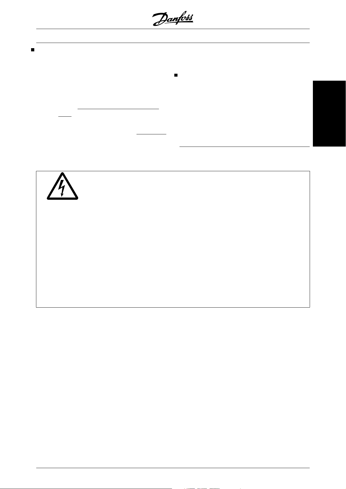
Touching the electrical parts may be fatal - even after the equipment has been disconnected from mains.
Also make sure that other voltage inputs have been disconnected, such as external 24 V DC, load-sharing (linkage
of DC intermediate circuit), as well as the motor connection for kinetic back-up.
VLT 5001 - 5006, 200-240 V: wait at least 4 minutes
VLT 5008 - 5052, 200-240 V: wait at least 15 minutes
VLT 5001 - 5006, 380-500 V: wait at least 4 minutes
VLT 5008 - 5062, 380-500 V: wait at least 15 minutes
VLT 5072 - 5302, 380-500 V: wait at least 20 minutes
VLT 5352 - 5552, 380-500 V: wait at least 40 minutes
VLT 5001 - 5005, 525-600 V wait at least 4 minutes
VLT 5006 - 5022, 525-600 V: wait at least 15 minutes
VLT 5027 - 5062, 525-600 V: wait at least 30 minutes
VLT 5042 - 5352, 525-690 V: wait at least 20 minutes
VLT 5402 - 5602, 525-690 V: wait at least 30 minutes
these stop functions are not suffi-
the stop key
Warning:
Use on isolated mains
See section RFI Switch regarding use on isolated
mains.
It is important to follow the recommendations regarding installation on IT-mains, since sufficient protection
of the complete installation must be observed. Not taking care using relevant monitoring devices for ITmains may result in damage.
cy converter, or if a temporary overload or a
fault in the supply mains or the motor connection ceases.
Introduction
MG.52.B2.02 - VLT
®
is a registered Danfoss trademark 5
Page 7
®
VLT
5000 Design Guide
Introduction
This Design Guide is intended as a tool for use when designing a plant or system that includes VLT 5000 Series.
Specific technical publications on the VLT 5000 Series: Operating Instructions and Design Guide.
Operating Instructions: Gives instructions in optimum installation, commissioning and service.
Design Guide: Gives all required information for design purposes, and gives a good insight
into the technology, product range, technical data, etc.
The Operating Instructions include a Quick Setup instruction and are delivered with the unit.
When reading through this Design Guide, you will
come across various symbols that require special attention.
The symbols used are the following:
Indicates a general warning
NB!
Indicates something to be noted by the
reader
Indicates a high-voltage warning
6 MG.52.B2.02 - VLT
®
is a registered Danfoss trademark
Page 8
®
VLT
Available literature
Below is a list of the literature available for VLT 5000. It must be noted that there may be deviations from one
country to another.
Supplied with the unit:
Operating instructions MG.51.AX.YY
High Power Installation Guide MI.90.JX.YY
Communication with VLT 5000:
VLT 5000 Profibus manual MG.10.EX.YY
VLT 5000 DeviceNet manual MG.50.HX.YY
VLT 5000 LonWorks manual MG.50.MX.YY
VLT 5000 Modbus manual MG.10.MX.YY
VLT 5000 Interbus manual MG.10.OX.YY
Application options for VLT 5000:
VLT 5000 SyncPos option manual MG.10.EX.YY
VLT 5000 Positioning controller manual MG.50.PX.YY
VLT 5000 Synchronising controller manual MG.10.NX.YY
Ring spinning option MI.50.ZX.02
Wobble function option MI.50.JX.02
Winder and Tension control option MG.50.KX.02
5000 Design Guide
Introduction
Instructions for VLT 5000:
Loadsharing MI.50.NX.02
VLT 5000 Brake resistors MI.90.FX.YY
Brake resistors for horizontal applications (VLT 5001 - 5011) (Only in English and German) MI.50.SX.YY
LC filter modules MI.56.DX.YY
Converter for encoder inputs (5V TTL to 24 V DC) (Only in combined English/German) MI.50.IX.51
Back Plate to VLT 5000 Series MN.50.XX.02
Various literature for VLT 5000:
Design Guide MG.51.BX.YY
Incorporating a VLT 5000 Profibus in a Simatic S5 SYSTEM MC.50.CX.02
Incorporating a VLT 5000 Profibus in a Simatic S7 SYSTEM MC.50.AX.02
Hoist and the VLT 5000 series MN.50.RX.02
Miscellaneous (only in English):
Protection against electrical hazards MN.90.GX.02
Choice of prefuses MN.50.OX.02
VLT on IT mains MN.90.CX.02
Filtering of harmonic currents MN.90.FX.02
Handling aggressive environments MN.90.IX.02
CI-TITM contactors - VLT® frequency converters MN.90.KX.02
VLT® frequency converters and UniOP operator panels MN.90.HX.02
X = version number
YY = language version
MG.52.B2.02 - VLT
®
is a registered Danfoss trademark 7
Page 9
VLT
®
5000 Design Guide
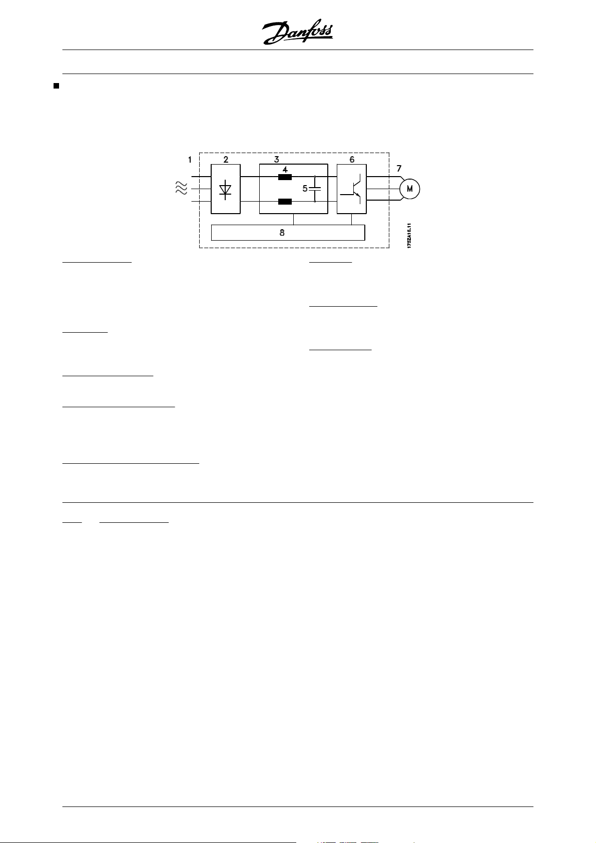
Control principle
A frequency converter rectifies AC voltage from mains
into DC voltage, after which this DC voltage is converted into a AC current with a variable amplitude and
frequency.
1. Mains voltage
3 x 200 - 240 V AC, 50 / 60 Hz.
3 x 380 - 500 V AC, 50 / 60 Hz.
3 x 525 - 600 V AC, 50 / 60 Hz.
3 X 525 - 690 V AC, 50 / 60 Hz.
2. Rectifier
A three-phase rectifier bridge that rectifies AC current
into DC current.
3. Intermediate circuit
DC voltage = 1.35 x mains voltage [V].
4. Intermediate circuit coils
Smooth the intermediate circuit current and limit the
load on mains and components (mains transformer,
wires, fuses and contactors).
The motor is thus supplied with variable voltage and
frequency, which enables infinitely variable speed
control of three-phased, standard AC motors.
6. Inverter
Converts DC voltage into variable AC voltage with a
variable frequency.
7. Motor voltage
Variable AC voltage, 0-100% of mains supply voltage.
Variable frequency: 0.5-132/0.5-1000 Hz.
8. Control card
This is where to find the computer that controls the inverter which generates the pulse pattern by which the
DC voltage is converted into variable AC voltage with
a variable frequency.
5. Intermediate circuit capacitors
Smooth the intermediate circuit voltage.
plus
VVC
control principle
The frequency converter features an inverter control
SYSTEM called VVC
plus
, which is a further development of the Voltage Vector Control (VVC) known i.e.
from Danfoss VLT 3000 Series.
plus
VVC
controls an induction motor by energizing it
with a variable frequency and a voltage that matches
it. If the motor load is changed, the magnetisation of
the motor changes too, and so does its speed. Consequently, the motor current is measured continuously
and the actual voltage requirement and slip of the motor are calculated from a motor model. Motor frequency and voltage are adjusted to ensure that the motor
operating point remains optimum under varying conditions.
The development of the VVC
plus
principle is the result
of a wish to maintain robust, sensorless regulation that
is tolerant to different motor characteristics without
motor derating being required.
First and foremost, the current measurement and the
motor model have been improved. The current is split
into magnetising and torque-generating parts and provides for much better and quicker estimation of the
actual motor loads. It is now possible to compensate
for rapid load changes. Full torque as well as extremely
accurate speed control can now be obtained even at
low speeds or even at standstill.
In a "special motor mode", permanent magnet synchronous motors and/or parallel motors can be used.
Good torque control properties, smooth transitions to
and from current limit operation and robust pull-out
torque protection are ensured.
8 MG.52.B2.02 - VLT
®
is a registered Danfoss trademark
Page 10

VLT
®
5000 Design Guide
After automatic motor adaptation, VVC
plus
will help to
ensure extremely accurate motor control.
plus
Advantages of the VVC
Accurate speed control, now even at low
-
control SYSTEM:
speed
Quick response from received signal to full
-
motor shaft torque
Good compensation for step loads
-
Controlled transition from normal operation to
-
current limit operation (and vice versa)
Reliable pull-out torgue protection through-
-
out the speed range, also in the case of field
weakening
Great tolerance towards varying motor data
-
Torque control, comprising control of both the
-
torque-generating and the magnetising component of the current
Full holding torque (closed loop)
-
As standard, the frequency converter comes with a
number of integral components that would normally
have to be acquired separately. These integral components (RFI filter, DC coils, screen clamps and serial
communication port) are space-savers that simplify installation, since the frequency converter fulfills most
requirements without any supplementary components.
Programmable control inputs and signal outputs in four
Setups
The frequency converter uses a digital technique
which makes it possible to program the different control inputs and signal outputs and to select four different user-defined Setups for all parameters.
For the user, it is easy to program the desired functions
by means of the control panel on the frequency converter or the RS 485 user interface.
Protection against mains interference
The frequency converter is protected against the transients that occur in the mains supply, e.g. when switching power factor correction or when fuses blow.
The rated motor voltage and full torque can be maintained all the way down to 10% undervoltage in the
mains supply.
Minor interference on mains
Since as standard the frequency converter features
intermediate circuit coils, there is only a small amount
of harmonic mains supply interference. This ensures
a good power factor and lower peak current, which reduces the load on the mains installation.
Advanced VLT protection
Current measurement on all three motor phases provides perfect protection of the frequency converter
against earthing and short-circuiting faults on the motor connection.
Constant monitoring of all three motor phases enables
switching on the motor output, e.g. by means of a contactor.
Efficient monitoring of the three mains supply phases
ensures that the unit stops in the case of phase failure.
This avoids overloading the inverter and the capacitors
in the intermediate circuit, which would dramatically
reduce the service life of the frequency converter.
As standard, the frequency converter features integral
thermal protection. If a situation of thermal overload
occurs, this function cuts out the inverter.
Reliable galvanic isolation
In the frequency converter, all control terminals as well
as terminals 1-5 (AUX relays) are supplied by or connected to circuits that comply with PELV requirements
in relation to the mains potential.
Advanced motor protection
The frequency converter features integrated electronic, thermal motor protection.
The frequency converter calculates the motor temperature on the basis of current, frequency and time.
As opposed to the traditional bimetallic protection,
electronic protection takes account of the reduction in
cooling at low frequencies that comes from reduced
fan speed (motors with internal ventilation).
Thermal motor protection is comparable to a normal
motor thermistor.
To obtain maximum protection against overheating of
the motor if the motor is covered or blocked, or if the
fan fails, a thermistor can be integrated and connected
to the thermistor input of the frequency converter (terminals 53/54), see parameter 128 of the Operating
Instructions.
Technology
MG.52.B2.02 - VLT
®
is a registered Danfoss trademark 9
Page 11
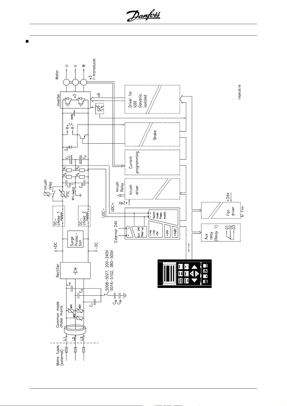
Key Diagram for VLT 5001–5027
200-240 V, VLT 5001–5102 380-500V,
VLT 5001–5062 525-600 V
VLT
®
5000 Design Guide
10 MG.52.B2.02 - VLT
®
is a registered Danfoss trademark
Page 12
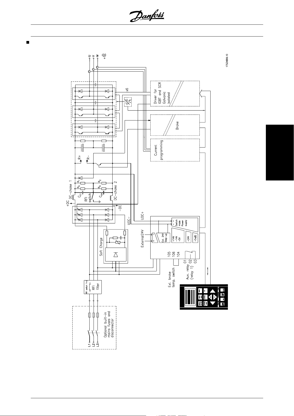
Key Diagram for VLT 5122-5552 380-500 V and VLT
5042-5602 525-690 V
VLT
®
5000 Design Guide
Technology
Note: The RFI switch has no function in the 525-690 V
drives.
MG.52.B2.02 - VLT
®
is a registered Danfoss trademark 11
Page 13
VLT
®
5000 Design Guide
How to select your frequency converter
A frequency converter must be selected on the basis
of the given motor current at maximum load on the unit.
The rated output current I
must be equal to or
VLT,N
higher than the required motor current.
Normal/high overload torque mode
This function enables the frequency converter to perform a constant 100% torque, using an oversize motor.
The choice between a normal or a high overload torque characteristic is made in parameter 101.
This is also where to choose between a high/normal
constant torque characteristic (CT) or a high/normal
VT torque characteristic.
If a high torque characteristic is chosen, a rated motor
with the frequency converter obtains up to 160% torque for 1 min. in both CT and VT.
The frequency converter is supplied for four mains
voltage ranges: 200-240 V, 380-500 V, 525-600 V and
525-690 V.
If a normal torque characteristic is chosen, an oversize
motor allows up to 110% torque performance for up to
1 min. in both CT and VT. This function is used mainly
for pumps and fans, since these applications do not
require an overload torque.
The advantage of choosing a normal torque characteristic for an oversize motor is that the frequency
converter will be able constantly to yield 100% torque,
without derating as a result of a bigger motor.
NB!
This function
cannot be chosen for VLT
5001-5006, 200-240 Volts, and VLT
5001-5011, 380-500 Volts.
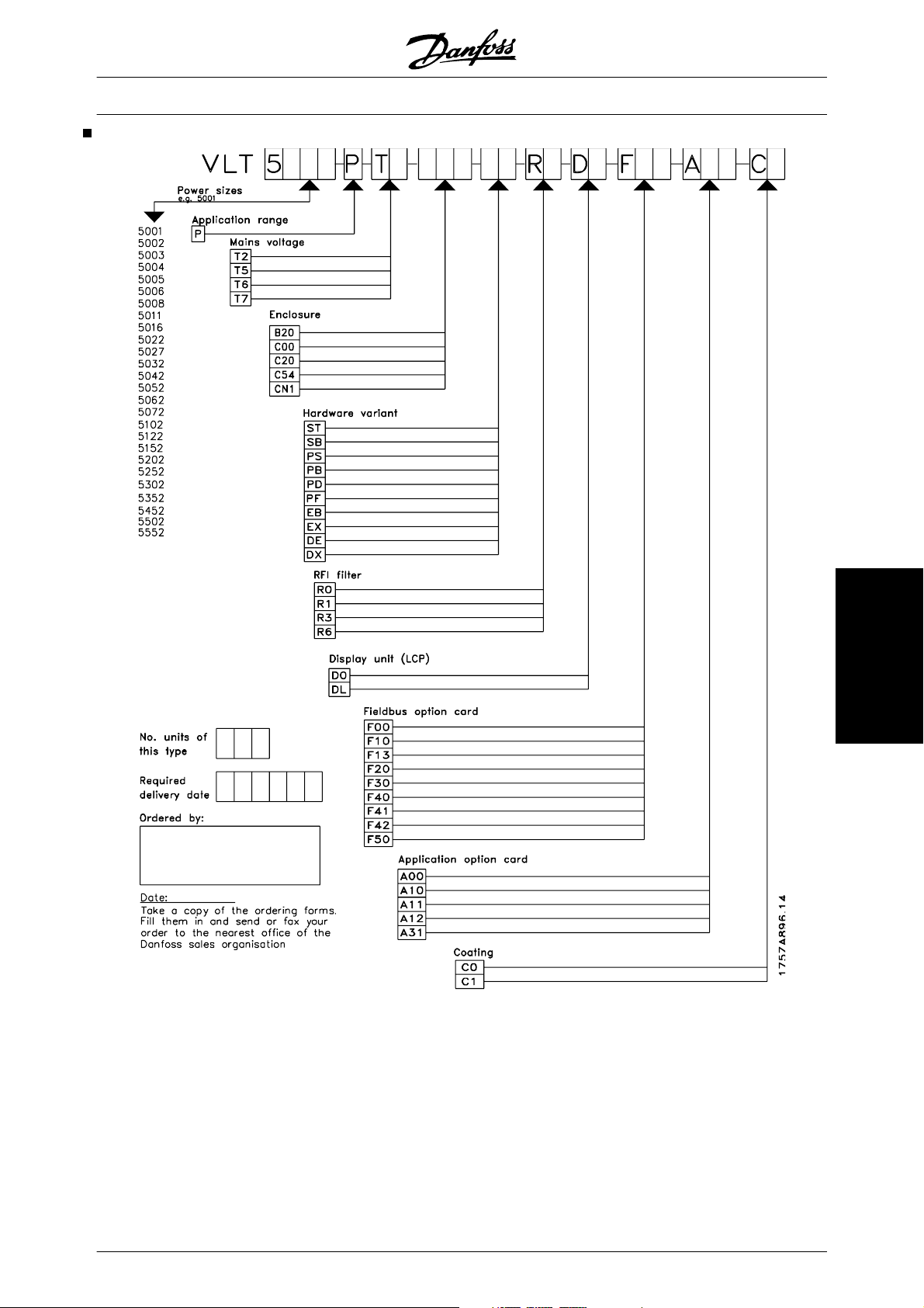
Type code ordering number string
The VLT 5000 series frequency converter is offered in
a large number of variants. On the basis of your order,
the frequency converter is given an ordering number
that can be seen from the nameplate on the unit. The
number may look as follows:
VLT5008PT5B20EBR3DLF10A10C0
This means that the frequency converter is configured
as a:
• 5,5 kW unit at 160% torque (Position 1-7 VLT 5008)
• Process control card (Position 8 - P)
• 380-500 V three phase supply (Position 9-10
- T5)
• Bookstyle IP20 enclosure (Position 11-13 B20)
• Extended hardware version with brake (Position 14-15 - EB)
• Built in RFI filter (Position 16-17 - R3)
• Supplied with display (Position 18-19 - DL)
• Built in Profibus option (Position 20-22 - F10)
• Built in programmable SyncPos controller
(Position 23-25 - A10)
• Uncoated printed circuit boards (Position
26-27 - C0)
Variants and options possible
In the following you will find an overview of possible
variants that can be put together. Please refer to the
description of the designation below.
12 MG.52.B2.02 - VLT
®
is a registered Danfoss trademark
Page 14
®
VLT
5000 Design Guide
VLT 5001-5052, 200-240 V units
Typecode designation: T2
Powersize (kW) Type Enclosure HW variant RFI filter
Torque
110% 160%
0.75 5001 x x x x x x x
1.1 5002 x x x x x x x
1.5 5003 x x x x x x x
2.2 5004 x x x x x x x
3 5005 x x x x x x x
3.7 5006 x x x x x x x
7.5 5.5 5008 x x x x x x x
11 7.5 5011 x x x x x x x
15 11 5016 x x x x x x x
18.5 15 5022 x x x x x x x
22 18.5 5027 x x x x x x x
30 22 5032 x x x x x x x x
37 30 5042 x x x x x x x x
45 37 5052 x xxxxx xx
C00 Compact IP00 DE Extended with brake, disconnect and fuses
B20 Bookstyle IP20 DX Extended without brake, with disconnect and fuses
C20 Compact IP20 PS Standard with 24 V supply
CN1 Compact Nema1 PB Standard with 24 V supply, brake, fuse and disconnect
C54 Compact IP54 PD Standard with 24 V supply, fuse and disconnect
ST Standard PF Standard with 24 V supply and fuse
SB Standard with brake R0 Without filter
EB Extended with brake R1 Class A1 filter
EX Extended without brake R3 Class A1 and B filter
9-10 11-13 11-13 11-13 11-13 11-13 14-15 14-15 14-15 16-17 16-17 16-17
C00 B20 C20 CN1 C54 ST SB EB R0 R1 R3
How to select your fre-
quency converter
MG.52.B2.02 - VLT
®
is a registered Danfoss trademark 13
Page 15
VLT
®
5000 Design Guide
C00 B20 C20 CN1 C54 ST SB EB EX DE DX PS PB PD PF R0 R1 R3 R6
9-10 11-13 11-13 11-13 11-13 11-13 14-15 14-15 14-15 14-15 14-15 14-15 14-15 14-15 14-15 14-15 16-17 16-17 16-17 16-17
Powersize (kW) Type Enclosure HW variant RFI filter
110% 160%
0.75 5001 x x x x x x x
1.1 5002 x x x x x x x
1.5 5003 x x x x x x x
2.2 5004 x x x x x x x
3 5005 x x x x x x x
3.7 5006 x x x x x x x
5.5 5008 x x x x x x x
7.5 5011 x x x x x x x
15 11 5016 x x x x x x x
18.5 15 5022 x x x x x x x
22 18.5 5027 x x x x x x x
30 22 5032 x x x x x x x
37 30 5042 x x x x x x x
45 37 5052 x x x x x x x
55 45 5062 x x x x x x x
75 55 5072 x x x x x x x
90 75 5102 x x x x x x x
110 90 5122 x x x x x x x x x x x x x x x x
132 110 5152 x x x x x x x x x x x x x x x x
160 132 5202 x x x x x x x x x x x x x x x x
200 160 5252 x x x x x x x x x x x x x x x x
250 200 5302 x x x x x x x x x x x x x x x x
315 250 5352 x x x x x x x x x x x x x x x
355 315 5452 x x x x x x x x x x x x x x x
400 355 5502 x x x x x x x x x x x x x x x
450 400 5552 x x x x x x x x x x x x x x x
VLT 5001-5552, 380-500 V units
Typecode designation: T5
Torque
14 MG.52.B2.02 - VLT
C00 Compact IP00 DE Extended with brake, disconnect and fuses
B20 Bookstyle IP20 DX Extended without brake, with disconnect and fuses
C20 Compact IP20 PS Standard with 24 V supply
CN1 Compact Nema1 PB Standard with 24 V supply, brake, fuse and disconnect
C54 Compact IP54 PD Standard with 24 V supply, fuse and disconnect
ST Standard PF Standard with 24 V supply and fuse
SB Standard with brake R0 Without filter
EB Extended with brake R1 Class A1 filter
EX Extended without brake R3 Class A1 and B filter
R6 Filter for marine installations
®
is a registered Danfoss trademark
Page 16
®
VLT
5000 Design Guide
VLT 5001-5062, 525-600 V units
Typecode designation: T6
Powersize (kW) Type Enclosure HW variant RFI filter
Torque
110%
1.1 0.75 5001 x x x x
1.5 1.1 5002 x x x x
2.2 1.5 5003 x x x x
3.0 2.2 5004 x x x x
4.0 3.0 5005 x x x x
5.5 4.0 5006 x x x x
7.5 5.5 5008 x x x x
7.5 7.5 5011 x x x x
15 11 5016 x x x x
18.5 15 5022 x x x x
22 18.5 5027 x x x x
30 22 5032 x x x x
37 30 5042 x x x x
45 37 5052 x x x x
55 45 5062 x xxx
160%
9-10 11-13 11-13 11-13 14-15 14-15 16-17
C00 C20 CN1 ST EB R0
VLT 5042-5602, 525-690 V units
Typecode designation: T7
Power size
Type Enclosure Hardware variant RFI filter
(kW)
Torque
C00 CN1 C54 ST SB EB EX DE DX PS PB PD PF R0
110%160
%
9-10 11-1311-1311-1314-1514-1514-1514-1514-1514-1514-1514-1514-1514-1516-1716-1
45 37 5042 X X X X X X X X X X X X X X X
55 45 5052 X X X X X X X X X X X X X X X
75 55 5062 X X X X X X X X X X X X X X X
90 75 5072 X X X X X X X X X X X X X X X
110 90 5102 X X X X X X X X X X X X X X X
132 110 5122 X X X X X X X X X X X X X X X
160 132 5152 X X X X X X X X X X X X X X X
200 160 5202 X X X X X X X X X X X X X X X
250 200 5252 X X X X X X X X X X X X X X X
315 250 5302 X X X X X X X X X X X X X X X
400 315 5352 X X X X X X X X X X X X X X X
500 400 5402 X X X X X X X X X X X X X X
560 500 5502 X X X X X X X X X X X X X X
630 560 5602 XXXXXXXXXXXXXX
1. R1 is not available with DX, PF and PD variants.
Voltage (position 9-10)
The drives are available in three voltage ratings.
Please be aware that some drives at 500 V supply
match a motor power size larger than 400 V - please
refer to the individual technical data.
Enclosure variants (position 11-13)
Bookstyle units are available for use in control cabinets
- the slim design allows many units in one cabinet.
Compact units are designed for mounting on walls or
machines. Higher power units are also available as
IP00 units for installation in control cabinets.
R1
1
7
quency converter
How to select your fre-
• T2 - 200-240 V three phase supply voltage
• T5 - 380-500 V three phase supply voltage
• T6 - 525-600 V three phase supply voltage
• T7 - 525-690 V three phase supply voltage
MG.52.B2.02 - VLT
®
is a registered Danfoss trademark 15
• C00 - Compact IP00 enclosure
• B20 - Bookstyle IP20 enclosure
• C20 - Compact IP20 enclosure
Page 17

VLT
®
5000 Design Guide
• CN1 - Compact Nema1 enclosure also fulfilling IP20/21 specifications
• C54 - Compact IP54 enclosure also fulfilling
NEMA12 demands
Hardware variants (position 14-15)
The hardware variants differ depending on power size.
• ST - Standard hardware
• SB - Standard hardware and additional brake
chopper
• EB - Extended hardware (24 V external supply for backup of control card and load sharing connections) and an additional brake
chopper
• EX - Extended hardware (24 V external supply for backup of control card and load sharing connections)
• DE - Extended hardware (24 V external supply for backup of control card and load sharing connections), brake chopper, disconnect
and fuses
• DX - Extended hardware (24 V external supply for backup of control card and load sharing connections), disconnect and fuses
• PS - Standard hardware with 24 V external
supply for backup of control card
• PB - Standard hardware with 24 V external
supply for backup of control card, brake
chopper, fuse and disconnect option
• PD - Standard hardware with 24 V external
supply for backup of control card, mains fuse
and disconnect option
• PF - Standard hardware with 24 V external
supply for backup of control card and built in
main fuses
RFI filter variants (position 16-17)
Different RFI filter variants offer the possibility to comply with class A1 and class B according to EN55011.
• R0 - No filter performance specified
• R1 - Compliance with class A1 filter
• R3 - Compliance with class B and A1
• R6 - Compliance with marine approvals (VLT
5122-5302, 380-500 V)
Display (position 18-19)
The control unit (display and keypad)
• D0 - No display in the unit (not possible for
IP54 enclosures as well as IP21 VLT
5352-5552, 380-480 V and VLT 5402 - 5602,
525-690 V)
• DL - Display supplied with the unit
Field bus option (position 20-22)
A wide selection of high performance field bus options
is available
• F0 - No field bus option built in
• F10 - Profibus DP V0/V1 12 Mbaud
• F13 - Profibus DP V0/FMS 12 Mbaud
• F20 - Modbus Plus
• F30 - DeviceNet
• F40 - LonWorks - Free topology
• F41 - LonWorks - 78 kbps
• F42 - LonWorks - 1,25 Mbps
• F50 - Interbus
Application options (position 23-25)
Several application options are available to enhance
the functionality of the frequency converter
• A00 - No option built in
• A10 - SyncPos programmable controller (not
possible with Modbus Plus and LonWorks)
• A11 - Synchronising controller (not possible
with Modbus Plus and LonWorks)
• A12 - Positioning controller (not possible with
Modbus Plus and LonWorks)
• A31 - Additional relays - 4 relays for 250 VAC
(not possible with field bus options)
Coating (position 26-27)
To increase protection of the drive against aggressive
environments it is possible to order coated printed circuit boards.
• C0 - Non coated boards (VLT 5352-5552,
380-500 V and VLT 5042-5602, 525-690 V)
only available with coated boards)
• C1 - Coated boards
Compliance depends on cable length. Please be
aware that some power sizes always have built in filters from factory.
16 MG.52.B2.02 - VLT
®
is a registered Danfoss trademark
Page 18
Ordering form VLT 5000 Series - Typecode
VLT
®
5000 Design Guide
How to select your fre-
quency converter
MG.52.B2.02 - VLT
®
is a registered Danfoss trademark 17
Page 19

VLT
®
5000 Design Guide
Selection of modules and accessories
Danfoss offers a wide range of modules and accessories for VLT 5000 Series.
Sine-wave filter module
The sine-wave filter reduces the voltage rise time (dU/
dt) and the ripple current (ΔI) to the motor, thereby
making current and voltage almost sinusoidal. The
acoustic motor noise is therefore reduced to a minimum.
See also instructions MI.56.DX.51.
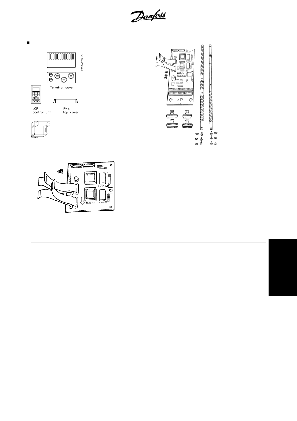
LCP control unit
Control unit with display and keypad for programming
VLT frequency converters. Available as an option for
IP 00 and IP 20 units.
Enclosure: IP 65.
Remote-mounting kits for LCP
The remote kit option makes it possible to move the
display from the frequency converter e.g. to the front
panel of an integrated cabinet.
Technical data
Enclosure: IP 65 front
Max. cable length
between VLT and unit: 3 m
Communication std: RS 422
Reference is also made to instructions MI.56.AX.51
(IP 20) and MI.56.GX.52 (IP 54).
VLT type 5016-5102, 380-500 V
VLT type 5016-5062, 525-600 V
Contactors
Danfoss also manufactures a complete range of contactors.
Brake resistors
Brake resistors are used in applications where high
dynamics are needed or a high inertia load has to be
stopped. The brake resistor is used to remove the energy, see also Instructions MI.50.SX.YY and MI.
90.FX.YY.
Harmonic filter
Harmonic currents do not directly affect the electricity
consumption but has an impact on following conditions:
Higher total current to be handled by the installations
Increases load on transformer (sometimes it
-
will require a larger transformer, particular at
retrofit)
Increases heat losses in transformer and in-
-
stallation
In some cases demands larger cables,
-
switches and fuses
IP 4x top cover
IP 4x top cover is an optional enclosure element available for IP 20 Compact units.
If an IP 4x top cover is used, an IP 20 unit is upgraded
to comply with enclosure IP 4x from the top. In practice,
this means that the unit complies with IP 40 on upper,
horizontal surfaces.
A top cover is available for the following Compact
units:
VLT type 5001-5006, 200-240 V
VLT type 5001-5011, 380-500 V
VLT type 5001-5011, 525-600 V
Terminal cover
Using a terminal cover, it is possible to field mount an
IP 20 unit, type VLT 5008-5052.
A terminal cover is available for the following compact
units:
VLT type 5008-5027, 200-240 V
Higher voltage distortion due to higher current
Increase risk for disturbing electronic equip-
-
ment connected to same grid
A high percentage of rectifier load from eg frequency
converters, will increase the harmonic current, which
must be reduced to avoid the above consequences.
Therefore the frequency converter has as standard,
built in DC coils reducing the total current with about
40% (compared to devices without any arrangement
for harmonic suppression), down to 40-45% ThiD.
In some cases there is a need for further suppression
(eg retrofit with frequency converters). For this purpose Danfoss can offer two advanced harmonic filters
AHF05 and AHF10, bringing the harmonic current
down to around 5% and 10% respectively. For further
details see instruction MG.80.BX.YY.
18 MG.52.B2.02 - VLT
®
is a registered Danfoss trademark
Page 20

VLT
®
5000 Design Guide
PC Software tools
PC Software - MCT 10
All drives are equipped with a serial communication
port. We provide a PC tool for communication between
PC and frequency converter, VLT Motion Control Tool
MCT 10 Set-up Software.
MCT 10 Set-up Software
MCT 10 has been designed as an easy to use interactive tool for setting parameters in our frequency
converters.
The MCT 10 Set-up Software will be useful for:
• Planning a communication network off-line.
MCT 10 contains a complete frequency converter database
• Commissioning frequency converters on line
• Saving settings for all frequency converters
• Replacing a drive in a network
• Expanding an existing network
• Future developed drives will be supported
MCT 10 Set-up Software support Profibus DP-V1 via
a Master class 2 connection. It makes it possible to on
line read/write parameters in a frequency converter via
the Profibus network. This will eliminate the need for
an extra communication network.
The MCT 10 Set-up Software Modules
The following modules are included in the software
package:
MCT 10 Set-up Software
Setting parameters
Copy to and from frequency converters
Documentation and print out of parameter settings incl. diagrams
SyncPos
Creating SyncPos programme
Ordering number:
Please order your CD containing MCT 10 Set-up Software using code number 130B1000.
MCT 31
The MCT 31 harmonic calculation PC tool enables
easy estimation of the harmonic distortion in a given
application. Both the harmonic distortion of Danfoss
frequency converters as well as non-Danfoss frequency converters with different additional harmonic reduc-
Modbus RTU
MODBUS RTU (Remote Terminal Unit) Protocol is a
messaging structure developed by Modicon in 1979,
used to establish master-slave/client-server communication between intelligent devices.
MODBUS is used to monitor and program devices; to
communicate intelligent devices with sensors and instruments; to monitor field devices using PCs and
HMIs.
MODBUS is often applied in Gas and Oil applications,
but also in building, infrastructure, transportation and
energy, applications are making use of its benefits.
tion measurements, such as Danfoss AHF filters and
12-18-pulse rectifiers, can be calculated.
Ordering number:
Please order your CD containing the MCT 31 PC tool
using code number 130B1031.
quency converter
How to select your fre-
MG.52.B2.02 - VLT
®
is a registered Danfoss trademark 19
Page 21
VLT
®
5000 Design Guide
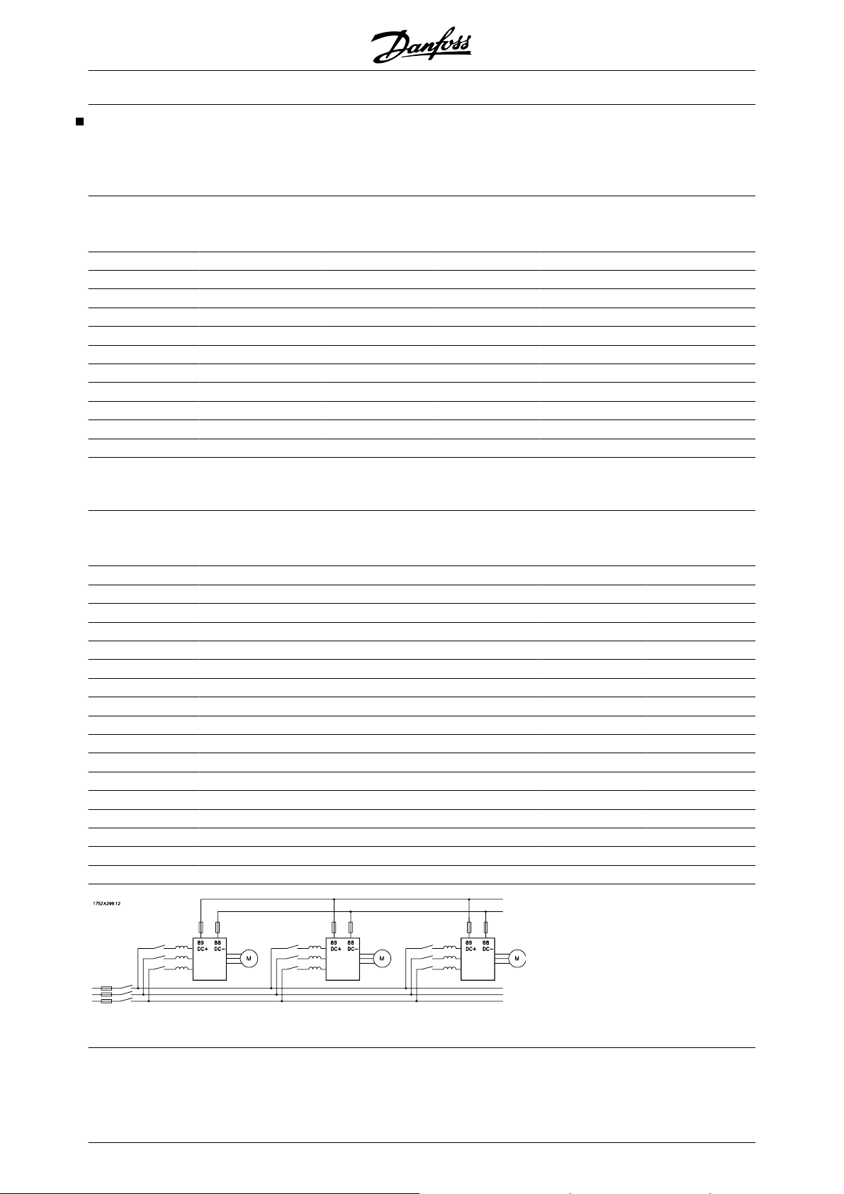
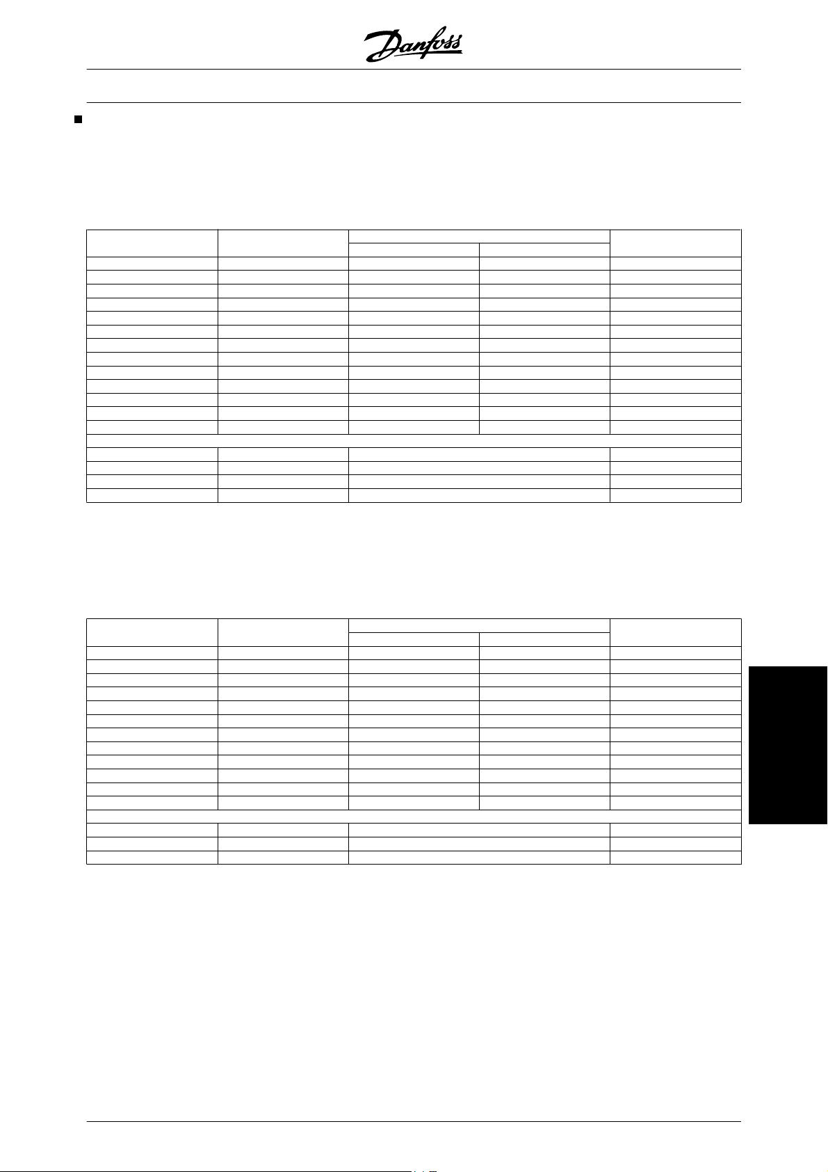
Line reactors for load sharing applications
Line reactors are used when connecting frequency
converters together in a load sharing application.
200 - 240 V units
VLT
type
Nominal
power at CT
[kW] [A] [%] [mH]
Input
current
Voltage
drop
Inductivity Ordering
number
5001 0.75 3.4 1.7 1.934 175U0021
5002 1.10 4.8 1.7 1.387 175U0024
5003 1.50 7.1 1.7 1.050 175U0025
5004 2.20 9.5 1.7 0.808 175U0026
5005 3.0 11.5 1.7 0.603 175U0028
5006 4.0 14.5 1.7 0.490 175U0029
5008 5.5 32.0 1.7 0.230 175U0030
5011 7.5 46.0 1.7 0.167 175U0032
5016 11.0 61.0 1.7 0.123 175U0034
5022 15.0 73.0 1.7 0.102 175U0036
5027 18.5 88.0 1.7 0.083 175U0047
380 - 500 V units
VLT
type
Nominal
power at CT
[kW] [A] [%] [mH]
Input
current
Voltage
drop
Inductivity Ordering
number
5001 0.75 2.3 1 3.196 175U0015
5002 1.1 2.6 1 2.827 175U0017
5003 1.5 3.8 1 1.934 175U0021
5004 2.2 5.3 1 1.387 175U0024
5005 3 7.0 1 1.050 175U0025
5006 4 9.1 1 0.808 175U0026
5008 5.5 12.2 1 0.603 175U0028
5011 7.5 15.0 1 0.490 175U0029
5016 11 32.0 1 0.230 175U0030
5022 15 37.5 1 0.196 175U0031
5027 18.5 44.0 1 0.167 175U0032
5032 22 60.0 1 0.123 175U0034
5042 30 72.0 1 0.102 175U0036
5052 37 89.0 1 0.083 175U0047
5062 45 104.0 1 0.070 175U1009
5072 55 144.6 1 0.051 175U0070
5102 75 174.1 1 0.042 175U0071
See also instruction MI.50.NX.YY for further information.
20 MG.52.B2.02 - VLT
®
is a registered Danfoss trademark
Page 22
Accessories for VLT 5000 Series
IP 20 bottom cover
®
VLT
5000 Design Guide
Application option
Memory option
Product range
MG.52.B2.02 - VLT
®
is a registered Danfoss trademark 21
Page 23
®
VLT
5000 Design Guide
Ordering numbers, misc. hardware:
Type
IP 4x top cover/NEMA 1 kit
IP 4x top cover/NEMA 1 kit
NEMA 12 bonding plate
NEMA 12 bonding plate
Description Ordering no.
1)
Option, VLT 5001-5006, 200-240 V 175Z0928
1)
Option, VLT 5001-5011, 380-500 V and 525-600 V 175Z0928
2)
Option, VLT 5001-5006, 200-240 V 175H4195
2)
Option, VLT 5001-5011, 380-500 V 175H4195
IP 20 terminal cover Option, VLT 5008-5016, 200-240 V 175Z4622
IP 20 terminal cover Option, VLT 5022-5027, 200-240 V 175Z4623
IP 20 terminal cover Option, VLT 5016-5032, 380-500 V and 525-600 V 175Z4622
IP 20 terminal cover Option, VLT 5042-5062, 380-500 V and 525-600 V 175Z4623
IP 20 terminal cover Option, VLT 5072-5102, 380-500 V 175Z4280
IP 20 bottom cover VLT 5032-5052, 200 - 240 V 176F1800
Terminal Adapter Kit VLT 5032-5052, 200 - 240 V IP 00/Nema 1(IP 20), ST 176F1805
Terminal Adapter Kit VLT 5032-5052, 200 - 240 V IP 00/Nema 1(IP 20), SB 176F1806
Terminal Adapter Kit VLT 5032-5052, 200 - 240 V IP 00/Nema 1(IP 20), EB 176F1807
Terminal Adapter Kit VLT 5032-5052, 200 - 240 V IP 54, ST 176F1808
Terminal Adapter Kit VLT 5032-5052, 200 - 240 V IP 54, SB 176F1809
Encoder converter / 5 V TTL Linedriver / 24 V DC 175Z1929
Rittal Installation Kits
Type
Rittal TS8 enclosure for IP00
Description Order No.
3)
Installation kit for 1800mm high enclosure, VLT5122-5152;
176F1824
380-500V, VLT 5042-5152, 525-690V
Rittal TS8 enclosure for IP00
Installation kit for 2000mm high enclosure, VLT5122-5152,
176F1826
3)
380-500V; VLT 5042-5152, 525-690V
Rittal TS8 enclosure for IP00
Installation kit for 1800mm high enclosure, VLT5202-5302,
176F1823
3)
380-500V; VLT 5202-5352, 525-690V
Rittal TS8 enclosure for IP00
Installation kit for 2000mm high enclosure, VLT5202-5302,
176F1825
3)
380-500V; VLT 5202-5352, 525-690V
Rittal TS8 enclosure for IP00
Installation kit for 2000mm high enclosure, VLT5352-5552,
176F1850
3)
380-500V; VLT 5402-5602, 525-690V
Floor stand for IP21 and IP54
enclosure
3)
Mains shield kit Protection kit:: VLT 5122-5302, 380-500 V
Option, VLT5122-5302, 380-500V; VLT 5042-5352,
525-690V
176F1827
176F0799
VLT 5042-5352, 525-690 V
Protection kit:: VLT 5352-5552, 380-500 V; VLT 5402-5602,
176F1851
525-690 V
1)
IP 4xNEMA top cover is for Compact IP 20 units only and is only intended for horizontal surfaces that comply
with IP 4x. The kit also contains a bonding plate (UL).
2)
NEMA 12 bonding plate (UL) is for compact IP 54 units only.
3)
For details: See High Power Installation Guide, MI.90.JX.YY.
Ordering numbers, control card options, etc.: LCP:
Type
Description Ordering no.
IP 65 LCP option Separate LCP, only for IP 20 units 175Z0401
LCP remote-mounting kit/
IP00/IP20/NEMA 1
LCP remote-mounting kit IP54Remote-mounting kit for LCP, for IP 54
Remote-mounting kit for LCP, for IP 00/20
units
175Z0850 incl. 3 m cable
175Z7802 incl. 3 m cable
units
Cable for LCP Separate cable 175Z0929 3 m cable
LCP: Control unit with display and keypad. Supplied excl. LCP.
22 MG.52.B2.02 - VLT
®
is a registered Danfoss trademark
Page 24

VLT
®
5000 Design Guide
Fieldbus options and accessories:
Profibus:
Uncoated Coated
Type Description Ordering no. Ordering no.
Profibus option DP V0/V1 incl. memory option 175Z0404 175Z2625
Profibus option DP V0/V1 excl. memory option 175Z0402
Profibus option DP V0/FMS incl. memory option 175Z3722 175Z3723
Type Description Ordering no.
Profibus Sub D9 Connector
for IP 20 / IP 00
LonWorks:
LonWorks option, Free topology
LonWorks option, Free topology excl. memory option 176F1512
LonWorks option, 78 KBPS incl. memory option 176F1501 176F1504
LonWorks option, 78 KBPS excl. memory option 176F1513
LonWorks option, 1.25 MBPS incl. memory option 176F1502 176F1505
LonWorks option, 1.25 MBPS excl. memory option 176F1514
DeviceNet:
VLT 5001-5027, 200-240 V
VLT 5001-5102, 380-500 V
VLT 5001-5062, 525-600 V
VLT 5032-5052, 200-240 V 176F1822
incl. memory option 176F1500 176F1503
175Z3568
DeviceNet option
DeviceNet option excl. memory option 176F1584
Modbus:
Modbus Plus for Compact units
Modbus Plus for Compact units excl. memory option 176F1559
Modbus Plus for Bookstyle units incl. memory option 176F1550 176F1552
Modbus Plus for Bookstyle units excl. memory option 176F1558
Modbus RTU Not factory mounted 175Z3362
Interbus:
Interbus
Interbus excl. memory option 175Z2900
Application options:
Programmable SyncPos controller
Synchronising controller Application option 175Z3053 175Z3056
Positioning controller Application option 175Z3055 175Z3057
Relay card option Application option 175Z2500 175Z2901
Winder Option Not factory mounted, SW version
Ring Spinning Option Not factory mounted, SW version
Wobble Option Not factory mounted, SW version
incl. memory option 176F1580 176F1581
incl. memory option 176F1551 176F1553
incl. memory option 175Z3122 175Z3191
Application option 175Z0833 175Z3029
175Z3245
3.40
175Z3463
3.41
175Z3467
3.41
Product range
Options can be ordered as factory built-in options, see ordering information.
For information on fieldbus and application option combatibility with older software versions, please contact your
Danfoss supplier.
If the Fieldbus options are to be used without application option a version with memory option must be ordered.
MG.52.B2.02 - VLT
®
is a registered Danfoss trademark 23
Page 25
Output Filters
The high speed switching of the frequency converter
produces some secondary effects, which influence the
motor and the enclosed environment. These side effects are addressed by two different filter types, -the
du/dt and the Sine-wave filter.
dU/dt filters
Motor insulation stresses are often caused by the combination of rapid voltage and current increase. The
rapid energy changes can also be reflected back to the
DC-line in the inverter and cause shut down. The du/
dt filter is designed to reduce the voltage rise time/the
rapid energy change in the motor and by that intervention avoid premature aging and flashover in the
motor insulation. du/dt filters have a positive influence
on the radiation of magnetic noise in the cable that
connects the drive to the motor. The voltage wave form
is still pulse shaped but the du/dt ratio is reduced in
comparison with the installation without filter.
®
VLT
5000 Design Guide
Sine-wave filters
Sine-wave filters are designed to let only low frequencies pass. High frequencies are consequently shunted
away which results in a sinusoidal phase to phase
voltage waveform and sinusoidal current waveforms.
With the sinusoidal waveforms the use of special frequency converter motors with reinforced insulation is
no longer needed. The acoustic noise from the motor
is also damped as a consequence of the wave condition.
Besides the features of the du/dt filter, the sine-wave
filter also reduces insulation stress and bearing currents in the motor thus leading to prolonged motor
lifetime and longer periods between services. Sinewave filters enable use of longer motor cables in applications where the motor is installed far from the
drive. The length is unfortunately limited because the
filter does not reduce leakage currents in the cables.
Ordering Numbers: Sine Wave Filter Modules,
200-500 VAC
Mains supply 3 x 200 to 500 V
Minimum switching frequency
5 kHz 120 Hz 130B2439 130B2404 2.5 A
5 kHz 120 Hz 130B2441 130B2406 4.5 A
5 kHz 120 Hz 130B2443 130B2408 8 A
5 kHz 120 Hz 130B2444 130B2409 10 A
5 kHz 120 Hz 130B2446 130B2411 17 A
4 kHz 60 Hz 130B2447 130B2412 24 A
4 kHz 60 Hz 130B2448 130B2413 38 A
4 kHz 60 Hz 130B2307 130B2281 48 A
3 kHz 60 Hz 130B2308 130B2282 62 A
3 kHz 60 Hz 130B2309 130B2283 75 A
3 kHz 60 Hz 130B2310 130B2284 115 A
3 kHz 60 Hz 130B2311 130B2285 180 A
3 kHz 60 Hz 130B2312 130B2286 260 A
3 kHz 60 Hz 130B2313 130B2287 410 A
3 kHz 60 Hz 130B2314 130B2288 480 A
2 kHz 60 Hz 130B2315 130B2289 660 A
2 kHz 60 Hz 130B2316 130B2290 750 A
2 kHz 60 Hz 130B2317 130B2291 880 A
2 kHz 60 Hz 130B2318 130B2292 1200 A
Maximum output fre-
quency
NB!
When using Sine-wave filters, the switching frequency should comply with filter specifications in par.
411 Switching Frequency.
Part No. IP20 Part No. IP00 Rated filter current at 50Hz
24 MG.52.B2.02 - VLT
®
is a registered Danfoss trademark
Page 26
VLT
Ordering Numbers: Sine-Wave Filter Modules, 525-600 VAC
Mains supply 3 x 525 to 690 V
Minimum switching frequency
2 kHz 60 Hz 130B2341 130B2321 13 A
2 kHz 60 Hz 130B2342 130B2322 28 A
2 kHz 60 Hz 130B2343 130B2323 45 A
2 kHz 60 Hz 130B2344 130B2324 76 A
2 kHz 60 Hz 130B2345 130B2325 115 A
2 kHz 60 Hz 130B2346 130B2326 165 A
2 kHz 60 Hz 130B2347 130B2327 260 A
2 kHz 60 Hz 130B2348 130B2329 303 A
1.5 kHz 60 Hz 130B2270 130B2241 430 A
1.5 kHz 60 Hz 130B2271 130B2242 530 A
1.5 kHz 60 Hz 130B2381 130B2337 660 A
1.5 kHz 60 Hz 130B2382 130B2338 765 A
1.5 kHz 60 Hz 130B2383 130B2339 940 A
1.5 kHz 60 Hz 130B2384 130B2340 1320 A
NB!
When using Sine-wave filters, the switching frequency should comply with filter specifications in par.
14-01 Switching Frequency.
Maximum output frequen-
cy
Part No. IP20 Part No. IP00
®
5000 Design Guide
Rated filter current at
50Hz
Ordering Numbers: du/dt Filters, 380-480 VAC Mains supply 3x380 to 3x480 V
Minimum switching frequen-cyMaximum output frequen-
cy
Part No. IP20 Part No. IP00
Rated filter current at 50
4 kHz 60 Hz 130B2396 130B2385 24 A
4 kHz 60 Hz 130B2397 130B2386 45 A
3 kHz 60 Hz 130B2398 130B2387 75 A
3 kHz 60 Hz 130B2399 130B2388 110 A
3 kHz 60 Hz 130B2400 130B2389 182 A
3 kHz 60 Hz 130B2401 130B2390 280 A
3 kHz 60 Hz 130B2402 130B2391 400 A
3 kHz 60 Hz 130B2277 130B2275 500 A
2 kHz 60 Hz 130B2278 130B2276 750 A
2 kHz 60 Hz 130B2405 130B2393 910 A
2 kHz 60 Hz 130B2407 130B2394 1500 A
2 kHz 60 Hz 130B2410 130B2395 2300 A
Ordering Numbers: du/dt Filters, 525-600 VAC
Mains supply 3x525 to 3x600 V
Minimum switching frequen-cyMaximum output frequen-
cy
Part No. IP20 Part No. IP00
Rated filter current at 50
4 kHz 60 Hz 130B2423 130B2414 28 A
4 kHz 60 Hz 130B2424 130B2415 45 A
3 kHz 60 Hz 130B2425 130B2416 75 A
3 kHz 60 Hz 130B2426 130B2417 115 A
3 kHz 60 Hz 130B2427 130B2418 165 A
3 kHz 60 Hz 130B2428 130B2419 260 A
3 kHz 60 Hz 130B2429 130B2420 310 A
3 kHz 60 Hz 130B2278 130B2235 430 A
2 kHz 60 Hz 130B2239 130B2236 530 A
2 kHz 60 Hz 130B2274 130B2280 630 A
2 kHz 60 Hz 130B2430 130B2421 765 A
2 kHz 60 Hz 130B2431 130B2422 1350 A
Hz
Product range
Hz
MG.52.B2.02 - VLT
®
is a registered Danfoss trademark 25
Page 27
®
VLT
5000 Design Guide
Brake resistors, VLT 5001 - 5052 / 200 - 240 V
Standard brake resistors
10% duty cycle 40% duty cycle
VLT
5001 145 0.065 175U1820 145 0.260 175U1920
5002 90 0.095 175U1821 90 0.430 175U1921
5003 65 0.250 175U1822 65 0.80 175U1922
5004 50 0.285 175U1823 50 1.00 175U1923
5005 35 0.430 175U1824 35 1.35 175U1924
5006 25 0.8 175U1825 25 3.00 175U1925
5008 20 1.0 175U1826 20 3.50 175U1926
5011 15 1.8 175U1827 15 5.00 175U1927
5016 10 2.8 175U1828 10 9.0 175U1928
5022 7 4.0 175U1829 7 10.0 175U1929
5027 6 4.8 175U1830 6 12.7 175U1930
5032 4.7 6 175U1954 Not available Not available Not available
5042 3.3 8 175U1955 Not available Not available Not available
5052 2.7 10 175U1956 Not available Not available Not available
Resistance
[ohm]
Power
[kW]
Code No. Resistance
[ohm]
Power
[kW]
Code No.
See instruction MI.90.FX.YY for further information.
Flatpack brake resistors for horizontal conveyors
VLT type Motor [kW] Resistor [ohm] Size Order number Max. duty cycle [%]
5001 0.75 150 150 Ω 100 W 175U1005 14.0
5001 0.75 150 150 Ω 200 W 175U0989 40.0
5002 1.1 100 100 Ω 100 W 175U1006 8.0
5002 1.1 100 100 Ω 200 W 175U0991 20.0
5003 1.5 72 72 Ω 200 W 175U0992 16.0
5004 2.2 47 50 Ω 200 W 175U0993 9.0
5005 3 35 35 Ω 200 W 175U0994 5.5
5005 3 35 72 Ω 200 W
5006 4 25 50 Ω 200 W
5008 5.5 20 40 Ω 200 W
5011 7.5 13 27 Ω 200 W
1. Order 2 pcs.
Mounting angle for flatpack resistor 100 W 175U0011
Mounting angle for flatpack resistor 200 W 175U0009
Mounting frame for 2 resistors broad (wide bookstyle)
175U0003
See Instruction MI.50.BX.YY for further information.
2 x 175U0992
2 x 175U0993
2 x 175U0996
2 x 175U0995
1
12.0
1
11.0
1
6.5
1
4.0
Mounting frame for 1 resistor narrow (slim bookstyle)
175U0002
Mounting frame for 2 resistors narrow (slim bookstyle)
175U0004
26 MG.52.B2.02 - VLT
®
is a registered Danfoss trademark
Page 28
®
VLT
5000 Design Guide
Ordering numbers, Brake resistors, VLT 5001 5552 / 380 - 500 V
Standard brake resistors
10% duty cycle 40% duty cycle
VLT
5001 620 0.065 175U1840 620 0.260 175U1940
5002 425 0.095 175U1841 425 0.430 175U1941
5003 310 0.250 175U1842 310 0.80 175U1942
5004 210 0.285 175U1843 210 1.35 175U1943
5005 150 0.430 175U1844 150 2.0 175U1944
5006 110 0.60 175U1845 110 2.4 175U1945
5008 80 0.85 175U1846 80 3.0 175U1946
5011 65 1.0 175U1847 65 4.5 175U1947
5016 40 1.8 175U1848 40 5.0 175U1948
5022 30 2.8 175U1849 30 9.3 175U1949
5027 25 3.5 175U1850 25 12.7 175U1950
5032 20 4.0 175U1851 20 13.0 175U1951
5042 15 4.8 175U1852 15 15.6 175U1952
5052 12 5.5 175U1853 12 19.0 175U1953
5062 9.8 15 175U2008 9.8 38.0 175U2007
5072 7.3 13 175U0069 7.3 38.0 175U0068
5102 5.7 15 175U0067 6.0 45.0 175U0066
2)
5122
2)
5152
2)
5202
2)
5252
2)
5302
5352-5552
Resistance
[ohm]
3.8 22 175U1960
3.2 27 175U1961
2.6 32 175U1962
2.1 39 175U1963
1.65 56
2)
1.3 72
Power
[kW]
Code No. Resistance
2 x 175U1061
2 x 175U1062
[ohm]
1)
1) 3)
Power
[kW]
Code No.
1. Order 2 pcs. Connect in parallel.
2. Resistors selected for 300 second cycle.
3. Rating fulfilled up to VLT 5452, the torque is reduced for VLT 5502 and VLT 5552.
See Instruction MI.90.FX.YY for further information.
Product range
MG.52.B2.02 - VLT
®
is a registered Danfoss trademark 27
Page 29

®
VLT
5000 Design Guide
Flatpack brake resistors for horizontal conveyors
VLT type Motor [kW] Resistor [ohm] Size Order number Max. duty cycle [%]
5001 0.75 630 620 Ω 100 W 175U1001 14.0
5001 0.75 630 620 Ω 200 W 175U0982 40.0
5002 1.1 430 430 Ω 100 W 175U1002 8.0
5002 1.1 430 430 Ω 200 W 175U0983 20.0
5003 1.5 320 310 Ω 200 W 175U0984 16.0
5004 2.2 215 210 Ω 200 W 175U0987 9.0
5005 3 150 150 Ω 200 W 175U0989 5.5
5005 3 150 300 Ω 200 W
5006 4 120 240 Ω 200 W
5008 5.5 82 160 Ω 200 W
5011 7.5 65 130 Ω 200 W
2 x 175U0985
2 x 175U0986
2 x 175U0988
2 x 175U0990
1
12.0
1
11.0
1
6.5
1
4.0
1. Order 2 pcs.
Mounting angle for flatpack resistor 100 W 175U0011.
Mounting angle for flatpack resistor 200 W 175U0009.
Mounting frame for 1 resistor narrow (slim bookstyle) 175U0002.
Mounting frame for 2 resistors narrow (slim bookstyle) 175U0004.
Mounting frame for 2 resistors broad (wide bookstyle) 175U0003.
See Instruction MI.50.BX.YY for further information.
For 525-600 V and 525-690 V please contact Danfoss.
28 MG.52.B2.02 - VLT
®
is a registered Danfoss trademark
Page 30
Ordering numbers, Harmonic filters
Harmonic filters are used to reduce mains harmonics
• AHF 010: 10% current distortion
• AHF 005: 5% current distortion
380-415 V, 50Hz
VLT
®
5000 Design Guide
I
AHF,N
10 A 4, 5.5 175G6600 175G6622 5006, 5008
19 A 7.5 175G6601 175G6623 5011
26 A 11 175G6602 175G6624 5016
35 A 15, 18.5 175G6603 175G6625 5022, 5027
43 A 22 175G6604 175G6626 5032
72 A 30, 37 175G6605 175G6627 5042, 5052
101 A 45. 55 175G6606 175G6628 5062, 5072
144 A 75 175G6607 175G6629 5102
180 A 90 175G6608 175G6630 5122
217 A 110 175G6609 175G6631 5152
289 A 132, 160 175G6610 175G6632 5202, 5252
324 A 175G6611 175G6633
Higher ratings can be achieved by paralleling the filter units
370 A 200 175G6688 175G6691 5302
434 A
578 A 315 Two 289 A units 5452
613 A 355 289 A and 324 A units 5502
648 A 400 Two 324 A units 5552
Typical Motor Used
[kW]
250 Two 217 A units 5352
Danfoss ordering number VLT 5000
AHF 005 AHF 010
Please note that the matching of the typical Danfoss frequency converter and filter is pre-calculated based on
400 V and assuming typical motor load (4 or 2 pole motor): VLT 5000 series is based on a max. 160 % torque
application. The pre-calculated filter current may be different than the input current ratings of VLT 5000 as stated
in the respective operating instructions, as these numbers are based on different operating conditions.
440-480 V, 60Hz
I
AHF,N
19 A 10, 15 175G6612 175G6634 5011, 5016
26 A 20 175G6613 175G6635 5022
35 A 25, 30 175G6614 175G6636 5027, 5032
43 A 40 175G6615 175G6637 5042
72 A 50, 60 175G6616 175G6638 5052, 5062
101 A 75 175G6617 175G6639 5072
144 A 100, 125 175G6618 175G6640 5102, 5122
180 A 150 175G6619 175G6641 5152
217 A 200 175G6620 175G6642 5202
289 A 250 175G6621 175G6643 5252
324 A 300 175G6689 175G6692 5302
Higher ratings can be achieved by paralleling the filter units
370 A 350 175G6690 175G6693 5352
506 A
578 A 500 Two 289 A units 5502
648 A 600 Two 324 A units 5552
Typical Motor Used
[HP]
450 217 A and 289 A units 5452
Danfoss ordering number VLT 5000
AHF 005 AHF 010
Product range
Please note that the matching of the typical Danfoss frequency converter and filter is pre-calculated based on
480 V and assuming typical motor load (4 or 2 pole motor): VLT 5000 series is based on a max. 160 % torque
application. The pre-calculated filter current may be different than the input current ratings of VLT 5000 as stated
in the respective operating instructions, as these numbers are based on different operating conditions.
MG.52.B2.02 - VLT
®
is a registered Danfoss trademark 29
Page 31

®
VLT
5000 Design Guide
500 V, 50 Hz
I
AHF,N
10 A 4, 5.5 175G6644 175G6656 5006, 5008
19 A 7.5, 11 175G6645 175G6657 5011, 5016
26 A 15, 18.5 175G6646 175G6658 5022, 5027
35 A 22 175G6647 175G6659 5032
43 A 30 175G6648 175G6660 5042
72 A 37, 45 175G6649 175G6661 5052, 5062
101 A 55, 75 175G6650 175G6662 5062, 5072
144 A 90, 110 175G6651 175G6663 5102, 5122
180 A 132 175G6652 175G6664 5152
217 A 160 175G6653 175G6665 5202
289 A 200 175G6654 175G6666 5252
Higher ratings can be achieved by paralleling the filter units
324 A 250 175G6655 175G6667 5302
434 A
469 A 355 180 A and 289 A units 5452
578 A 400 Two 289 A units 5502
648 A 500 Two 324 A units 5552
Typical Motor Used
[kW]
315 Two 217 A units 5352
Danfoss ordering number
AHF 005 AHF 010 VLT 5000
Please note that the matching of the typical Danfoss frequency converter and filter is pre-calculated based on
500 V and assuming typical motor load. VLT 5000 series is based on a 160 % torque application. The precalculated filter current may be varying from the input current ratings of VLT 5000 as stated in the respective
operating instructions, as these numbers are based on different operating conditions. For further combinations,
please consult MG.80.BX.YY.
690 V, 50 Hz
I AHF,N Typical motor used
43 37, 45 130B2328 130B2293 5042, 5042 5042
72 55, 75 130B2330 130B2295 5062, 5072 5052, 5062
101 90 130B2331 130B2296 5102 5072
144 110, 132 130B2333 130B2298 5122, 5152 5102, 5122
180 160 130B2334 130B2299 5202 5152
217 200 130B2335 130B2300 5252 5202
289 250 130B2331 &
324 315 130B2333 &
370 400 130B2334 &
469 500 130B2333 & 2 x
578 560 3 x 130B2334 2 x 130B2301 5602 5502
613 630 3 x 130B2335 130B2301 &
(kW)
Ordering no. AHF
005
130B2333
130B2334
130B2335
130B2334
Ordering no. AHF
010
130B2301 5302 5252
130B2302 5352 5302
130B2304 5352
130B2299 &
130B2301
130B2302
VLT 5000 160% VLT 5000 110%
5502 5402
5602
30 MG.52.B2.02 - VLT
®
is a registered Danfoss trademark
Page 32

®
VLT
General technical data
Mains supply (L1, L2, L3):
Supply voltage 200-240 V units 3 x 200/208/220/230/240 V ±10%
Supply voltage 380-500 V units 3 x 380/400/415/440/460/500 V ±10%
Supply voltage 525-600 V units 3 x 525/550/575/600 V ±10%
Supply voltage 525-690 V units 3 x 525/550/575/600/690 V ±10%
Supply frequency 48-62 Hz +/- 1 %
See the section on special conditions in the Design Guide
Max imbalance of supply voltage:
VLT 5001-5011, 380-500 V and 525-600 V and VLT 5001-5006, 200-240 V ±2.0% of rated supply voltage
VLT 5016-5062, 380-500 V and 525-600 V and VLT 5008-5027, 200-240 V ±1.5% of rated supply voltage
VLT 5072-5552, 380-500 V and VLT 5032-5052, 200-240 V ±3.0% of rated supply voltage
VLT 5042-5602, 525-690 V ±3.0% of rated supply voltage
True Power factor (λ)
Displacement Power Factor (cos φ)
No. of switchings on supply input L1, L2, L3 approx. 1 time/min.
See the section on special conditions in the Design Guide
VLT output data (U, V, W):
Output voltage 0-100% of supply voltage
Output frequency VLT 5001-5027, 200-240 V 0-132 Hz, 0-1000 Hz
Output frequency VLT 5032-5052, 200-240 V 0-132 Hz, 0-450 Hz
Output frequency VLT 5001-5052, 380-500 V 0-132 Hz, 0-1000 Hz
Output frequency VLT 5062-5302, 380-500 V 0-132 Hz, 0-450 Hz
Output frequency VLT 5352-5552, 380-500 V 0-132 Hz, 0-300 Hz
Output frequency VLT 5001-5011, 525-600 V 0-132 Hz, 0-700 Hz
Output frequency VLT 5016-5052, 525-600 V 0-132 Hz, 0-1000 Hz
Output frequency VLT 5062, 525-600 V 0-132 Hz, 0-450 Hz
Output frequency VLT 5042-5302, 525-690 V 0-132 Hz, 0-200 Hz
Output frequency VLT 5352-5602, 525-690 V 0-132 Hz, 0-150 Hz
Rated motor voltage, 200-240 V units 200/208/220/230/240 V
Rated motor voltage, 380-500 V units 380/400/415/440/460/480/500 V
Rated motor voltage, 525-600 V units 525/550/575 V
Rated motor voltage, 525-690 V units 525/550/575/690 V
Rated motor frequency 50/60 Hz
Switching on output Unlimited
Ramp times 0.05-3600 sec.
5000 Design Guide
0.90 nominal at rated load
near unity (>0.98)
Torque characteristics:
Starting torque, VLT 5001-5027, 200-240 V and VLT 5001-5552, 380-500 V 160% for 1 min.
Starting torque, VLT 5032-5052, 200-240 V 150% for 1 min.
Starting torque, VLT 5001-5062, 525-600 V 160% for 1 min.
Starting torque, VLT 5042-5602, 525-690 V 160% for 1 min.
Starting torque 180% for 0.5 sec.
Acceleration torque 100%
Overload torque, VLT 5001-5027, 200-240 V and VLT 5001-5552, 380-500 V,
VLT 5001-5062, 525-600 V, and VLT 5042-5602, 525-690 V
Overload torque, VLT 5032-5052, 200-240 V 150%
Arresting torque at 0 rpm (closed loop) 100%
The torque characteristics given are for the frequency converter at the high overload torque level (160%). At the
normal overload torque (110%), the values are lower.
MG.52.B2.02 - VLT
®
is a registered Danfoss trademark 31
160%
Technical data
Page 33

®
VLT
Braking at high overload torque level
200-240 V
5001-5027
5032-5052
380-500 V
5001-5102
5122-5252
5302
5352-5552
525-600 V
5001-5062
525-690 V
5042-5352
5402-5602
1) VLT 5502 at 90% torque. At 100% torque the braking duty cycle is 13%. At mains rating 441-500 V 100% torque the braking duty
cycle is 17%.
VLT 5552 at 80% torque. At 100% torque the braking duty cycle is 8%.
2) Based on 300 second cycle:
For VLT 5502 the torque is 145%.
For VLT 5552 the torque is 130%.
3) VLT 5502 at 80% torque.
VLT 5602 at 71% torque.
4) Based on 300 second cycle.
For VLT 5502 the torque is 128%.
For VLT 5602 the torque is 114%.
Cycle time (s) Braking duty cycle at 100% torque Braking duty cycle at over torque
120 Continuous 40%
300 10% 10%
120 Continuous 40%
600 Continuous 10%
600 40% 10%
600
120 Continuous 40%
600 40% 10%
600
40%
40%
1)
3)
5000 Design Guide
(150/160%)
2)
10%
4)
10%
Control card, digital inputs:
Number of programmable digital inputs 8
Terminal nos. 16, 17, 18, 19, 27, 29, 32, 33
Voltage level 0-24 V DC (PNP positive logics)
Voltage level, logical '0' < 5 V DC
Voltage level, logical '1' >10 V DC
Maximum voltage on input 28 V DC
Input resistance, R
i
2 kΩ
Scanning time per input 3 msec.
Reliable galvanic isolation: All digital inputs are galvanically isolated from the supply voltage (PELV). In addition, the
digital inputs can be isolated from the other terminals on the control card by connecting an external 24 V DC supply
and opening switch 4. VLT 5001-5062, 525-600 V do not meet PELV.
Control card, analogue inputs:
No. of programmable analogue voltage inputs/thermistor inputs 2
Terminal nos. 53, 54
Voltage level 0 - ±10 V DC (scalable)
Input resistance, R
i
10 kΩ
No. of programmable analogue current inputs 1
Terminal no. 60
Current range 0/4 - ±20 mA (scalable)
Input resistance, R
i
200 Ω
Resolution 10 bit + sign
Accuracy on input Max. error 1% of full scale
Scanning time per input 3 msec.
Terminal no. ground 55
Reliable galvanic isolation: All analogue inputs are galvanically isolated from the supply voltage (PELV)* as well as
other inputs and outputs.
* VLT 5001-5062, 525-600 V do not meet PELV.
32 MG.52.B2.02 - VLT
®
is a registered Danfoss trademark
Page 34

®
VLT
5000 Design Guide
Control card, pulse/encoder input:
No. of programmable pulse/encoder inputs 4
Terminal nos. 17, 29, 32, 33
Max. frequency on terminal 17 5 kHz
Max. frequency on terminals 29, 32, 33 20 kHz (PNP open collector)
Max. frequency on terminals 29, 32, 33 65 kHz (Push-pull)
Voltage level 0-24 V DC (PNP positive logics)
Voltage level, logical '0' < 5 V DC
Voltage level, logical '1' >10 V DC
Maximum voltage on input 28 V DC
Input resistance, R
i
2 kΩ
Scanning time per input 3 msec.
Resolution 10 bit + sign
Accuracy (100-1 kHz), terminals 17, 29, 33 Max. error: 0.5% of full scale
Accuracy (1-5 kHz), terminal 17 Max. error: 0.1% of full scale
Accuracy (1-65 kHz), terminals 29, 33 Max. error: 0.1% of full scale
Reliable galvanic isolation: All pulse/encoder inputs are galvanically isolated from the supply voltage (PELV)*. In addition, pulse and encoder inputs can be isolated from the other terminals on the control card by connecting an
external 24 V DC supply and opening switch 4.
* VLT 5001-5062, 525-600 V do not meet PELV.
Control card, digital/pulse and analogue outputs:
No. of programmable digital and analogue outputs 2
Terminal nos. 42, 45
Voltage level at digital/pulse output 0 - 24 V DC
Minimum load to ground (terminal 39) at digital/pulse output
600 Ω
Frequency ranges (digital output used as pulse output) 0-32 kHz
Current range at analogue output 0/4 - 20 mA
Maximum load to ground (terminal 39) at analogue output
500 Ω
Accuracy of analogue output Max. error: 1.5% of full scale
Resolution on analogue output. 8 bit
Reliable galvanic isolation: All digital and analogue outputs are galvanically isolated from the supply voltage (PELV)*,
as well as other inputs and outputs.
* VLT 5001-5062, 525-600 V do not meet PELV.
Control card, 24 V DC supply:
Terminal nos. 12, 13
Max. load (short-circuit protection) 200 mA
Terminal nos. ground 20, 39
Reliable galvanic isolation: The 24 V DC supply is galvanically isolated from the supply voltage (PELV)*, but has the
same potential as the analogue outputs.
* VLT 5001-5062, 525-600 V do not meet PELV.
Control card, RS 485 serial communication:
Terminal nos. 68 (TX+, RX+), 69 (TX-, RX-)
Reliable galvanic isolation: Full galvanic isolation.
Relay outputs:
1)
No. of programmable relay outputs 2
Terminal nos., control card (resistive load only) 4-5 (make)
Max. terminal load (AC1) on 4-5, control card 50 V AC, 1 A, 50 VA
MG.52.B2.02 - VLT
®
is a registered Danfoss trademark 33
Technical data
Page 35

®
VLT
5000 Design Guide
Max. terminal load (DC1 (IEC 947)) on 4-5, control card 25 V DC, 2 A / 50 V DC, 1 A, 50 W
Max. terminal load (DC1) on 4-5, control card for UL/cUL applications 30 V AC, 1 A / 42.5 V DC, 1A
Terminal nos., power card (resistive and inductive load) 1-3 (break), 1-2 (make)
Max. terminal load (AC1) on 1-3, 1-2, power card 250 V AC, 2 A, 500 VA
Max. terminal load (DC1 (IEC 947)) on 1-3, 1-2, power card 25 V DC, 2 A / 50 V DC, 1A, 50 W
Min. terminal load (AC/DC) on 1-3, 1-2, power card 24 V DC, 10 mA / 24 V AC, 100 mA
1) Rated values for up to 300,000 operations.
At inductive loads the number of operations are reduced by 50%, alternatively the current can be reduced by
50%, thus the 300,000 operations are maintained.
Brake resistor terminals (only SB, EB, DE and PB units):
Terminal nos. 81, 82
External 24 Volt DC supply:
Terminal nos. 35, 36
Voltage range 24 V DC ±15% (max. 37 V DC for 10 sec.)
Max. voltage ripple 2 V DC
Power consumption 15 W - 50 W (50 W for start-up, 20 msec.)
Min. pre-fuse 6 Amp
Reliable galvanic isolation: Full galvanic isolation if the external 24 V DC supply is also of the PELV type.
Cable lengths, cross-sections and connectors:
Max. motor cable length, screened cable 150 m
Max. motor cable length, unscreened cable 300 m
Max. motor cable length, screened cable VLT 5011 380-500 V 100 m
Max. motor cable length, screened cable VLT 5011 525-600 V
and VLT 5008, normal overload mode, 525-600 V
50 m
Max. brake cable length, screened cable 20 m
Max. loadsharing cable length, screened cable 25 m from frequency converter to DC bar.
Max. cable cross-section for motor, brake and loadsharing, see Electrical data
Max. cable cross-section for 24 V external DC supply
- VLT 5001-5027 200-240 V; VLT 5001-5102 380-500 V; VLT 5001-5062 525-600 V
4 mm2 /10 AWG
- VLT 5032-5052 200-240 V; VLT 5122-5552 380-500 V; VLT 5042-5602 525-690 V 2.5 mm2 /12 AWG
Max. cross-section for control cables 1.5 mm 2 /16 AWG
Max. cross-section for serial communication 1.5 mm2 /16 AWG
If UL/cUL is to be complied with, copper cable with temperature class 60/75°C must be used
(VLT 5001 - 5062 380 - 500 V, 525 - 600 V and VLT 5001 - 5027 200 - 240 V).
If UL/cUL is to be complied with, copper cable with temperature class 75°C must be used
(VLT 5072 - 5552 380 - 500 V, VLT 5032 - 5052 200 - 240 V, VLT 5042 - 5602 525 - 690 V).
Connectors are for use of both copper and aluminium cables, unless other is specified.
Accuracy of display readout (parameters 009-012):
Motor current [6] 0-140% load Max. error: ±2.0% of rated output current
Torque % [7], -100 - 140% load Max. error: ±5% of rated motor size
Output [8], power HP [9], 0-90% load Max. error: ±5% of rated output
Control characteristics:
Frequency range 0 - 1000 Hz
Resolution on output frequency ±0.003 Hz
System response time 3 msec.
34 MG.52.B2.02 - VLT
®
is a registered Danfoss trademark
Page 36

®
VLT
5000 Design Guide
Speed, control range (open loop) 1:100 of synchro. speed
Speed, control range (closed loop) 1:1000 of synchro. speed
Speed, accuracy (open loop) < 1500 rpm: max. error ± 7.5 rpm
Speed, accuracy (closed loop) < 1500 rpm: max. error ± 1.5 rpm
Torque control accuracy (open loop) 0- 150 rpm: max. error ±20% of rated torque
Torque control accuracy (speed feedback) Max. error ±5% of rated torque
All control characteristics are based on a 4-pole asynchronous motor
Externals:
Enclosure (dependent on power size) IP 00, IP 20, IP 21, Nema 1, IP 54
Vibration test 0.7 g RMS 18-1000 Hz random. 3 directions for 2 hours (IEC 68-2-34/35/36)
Max. relative humidity 93 % (IEC 68-2-3) for storage/transport
Max. relative humidity 95 % non condensing (IEC 721-3-3; class 3K3) for operation
Aggressive environment (IEC 721 - 3 - 3) Uncoated class 3C2
Aggressive environment (IEC 721 - 3 - 3) Coated class 3C3
Ambient temperature IP 20/Nema 1 (high overload torque 160%) Max. 45°C (24-hour average max. 40°C)
Ambient temperature IP 20/Nema 1 (normal overload torque 110%) Max. 40°C (24-hour average max. 35°C)
Ambient temperature IP 54 (high overload torque 160%) Max. 40°C (24-hour average max. 35°C)
Ambient temperature IP 54 (normal overload torque 110%) Max. 40°C (24-hour average max. 35°C)
Ambient temperature IP 20/54 VLT 5011 500 V Max. 40°C (24-hour average max. 35°C)
Ambient temperature IP 54 VLT 5042-5602, 525-690 V; and
5122-5552, 380-500 V (high overload torque 160%)
Max. 45°C (24-hour average max. 40°C)
Derating for high ambient temperature, see the Design Guide
Min. ambient temperature in full operation
0°C
Min. ambient temperature at reduced performance -10°C
Temperature during storage/transport -25 - +65/70°C
Max. altitude above sea level 1000 m
Derating for altitude over 1000 m above sealevel, see the Design Guide
EMC standards applied, Emission
EN 61000-6-3, EN 61000-6-4, EN 61800-3, EN 55011
EN 61000-6-2, EN 61000-4-2, EN 61000-4-3, EN 61000-4-4
EMC standards applied, Immunity
EN 61000-4-5, EN 61000-4-6, VDE 0160/1990.12
See section on special conditions in the Design Guide
VLT 5001-5062, 525 - 600 V do not comply with EMC or Low Voltage Directives.
IP54 units are not intended for direct outdoor installation. The IP54 rating does not relate to other exposures as sun,
icing, wind blown driving rain. Under such circumstances Danfoss recommends to install the units in an enclosure
designed for these environmental conditions. Alternatively, an installation at minimum 0.5 m above surface and
covered by a shed is recommended
VLT 5000 Series protection:
Electronic motor thermal protection against overload.
Temperature monitoring of heat-sink ensures that the frequency converter cuts out if the temperature reaches 90°
C for IP 00, IP 20 and Nema 1. For IP 54, the cut-out temperature is 80°C. An overtemperature can only be reset
when the temperature of the heat-sink has fallen below 60°C.
Technical data
MG.52.B2.02 - VLT
®
is a registered Danfoss trademark 35
Page 37

®
VLT
For the units mentioned below, the limits are as follows:
- VLT 5122, 380-500 V, cuts out at 75°C and can be reset if the temperature has fallen below 60°C.
- VLT 5152, 380-500 V, cuts out at 80°C and can be reset if the temperature has fallen below 60°C.
- VLT 5202, 380-500 V, cuts out at 95°C and can be reset if the temperature has fallen below 65°C.
- VLT 5252, 380-500 V, cuts out at 95°C and can be reset if the temperature has fallen below 65°C.
- VLT 5302, 380-500 V, cuts out at 105°C and can be reset if the temperature has fallen below 75°C.
- VLT 5352-5552, 380-500 V, cut out at 85°C and can be reset if the temperature has fallen below 60°C.
- VLT 5042-5122, 525-690 V, cut out at 75°C and can be reset if the temperature has fallen below 60°C.
- VLT 5152, 525-690 V, cuts out at 80°C and can be reset if the temperature has fallen below 60°C.
- VLT 5202-5352, 525-690 V, cut out at 100°C and can be reset if the temperature has fallen below 70°C.
- VLT 5402-5602, 525-690 V, cut out at 75°C and can be reset if the temperature has fallen below 60°C.
The frequency converter is protected against short-circuiting on motor terminals U, V, W.
The frequency converter is protected against earth fault on motor terminals U, V, W.
Monitoring of the intermediate circuit voltage ensures that the frequency converter cuts out if the intermediate circuit voltage becomes
too high or too low.
If a motor phase is missing, the frequency converter cuts out, see parameter 234 Motor phase monitor.
If there is a mains fault, the frequency converter is able to carry out a controlled decelleration.
If a mains phase is missing, the frequency converter will cut out when a load is placed on the motor.
5000 Design Guide
36 MG.52.B2.02 - VLT
®
is a registered Danfoss trademark
Page 38

Electrical data
Bookstyle and Compact, Mains supply 3 x 200 - 240 V
VLT
®
5000 Design Guide
According to international requirements VLT type 5001 5002 5003 5004 5005 5006
I
[A]
Output current
I
VLT, MAX
Output (240 V) S
Typical shaft output
Typical shaft output
Max. cable cross-section to motor,
brake and loadsharing [mm
Rated input current
Max. cable
cross-section power [mm
2
]/[AWG]2 )
2
]/[AWG] 2 )
(200 V)I
Max. pre-fuses
Efficiency
3)
VLT,N
(60 s) [A]
[kVA]
VLT,N
P
[kW]
VLT,N
P
[HP]
VLT,N
L,N
[-]/UL1) [A]
3.7 5.4 7.8 10.6 12.5 15.2
5.9 8.6 12.5 17 20 24.3
1.5 2.2 3.2 4.4 5.2 6.3
0.75 1.1 1.5 2.2 3.0 3.7
1 1.5 2 3 4 5
4/10
[A]
3.4 4.8 7.1 9.5 11.5 14.5
4/10
4/10 4/10 4/10 4/10 4/10
4/10 4/10 4/10 4/10 4/10
16/10 16/10 16/15 25/20 25/25 35/30
0.95 0.95 0.95 0.95 0.95 0.95
Weight IP 20 EB Bookstyle [kg] 7 7 7 9 9 9.5
Weight IP 20 EB Compact [kg] 8 8 8 10 10 10
Weight IP 54 Compact [kg] 11.5 11.5 11.5 13.5 13.5 13.5
Power loss at
max. load.
Enclosure
[W] 58 76 95 126 172 194
IP 20/
IP54
IP 20/
IP54
IP 20/
IP54
IP 20/
IP54
IP 20/
IP54
IP 20/
IP54
1. For type of fuse see section Fuses.
2. American Wire Gauge.
3. Measured using 30 m screened motor cables at rated load and rated frequency.
MG.52.B2.02 - VLT
®
is a registered Danfoss trademark 37
Technical data
Page 39
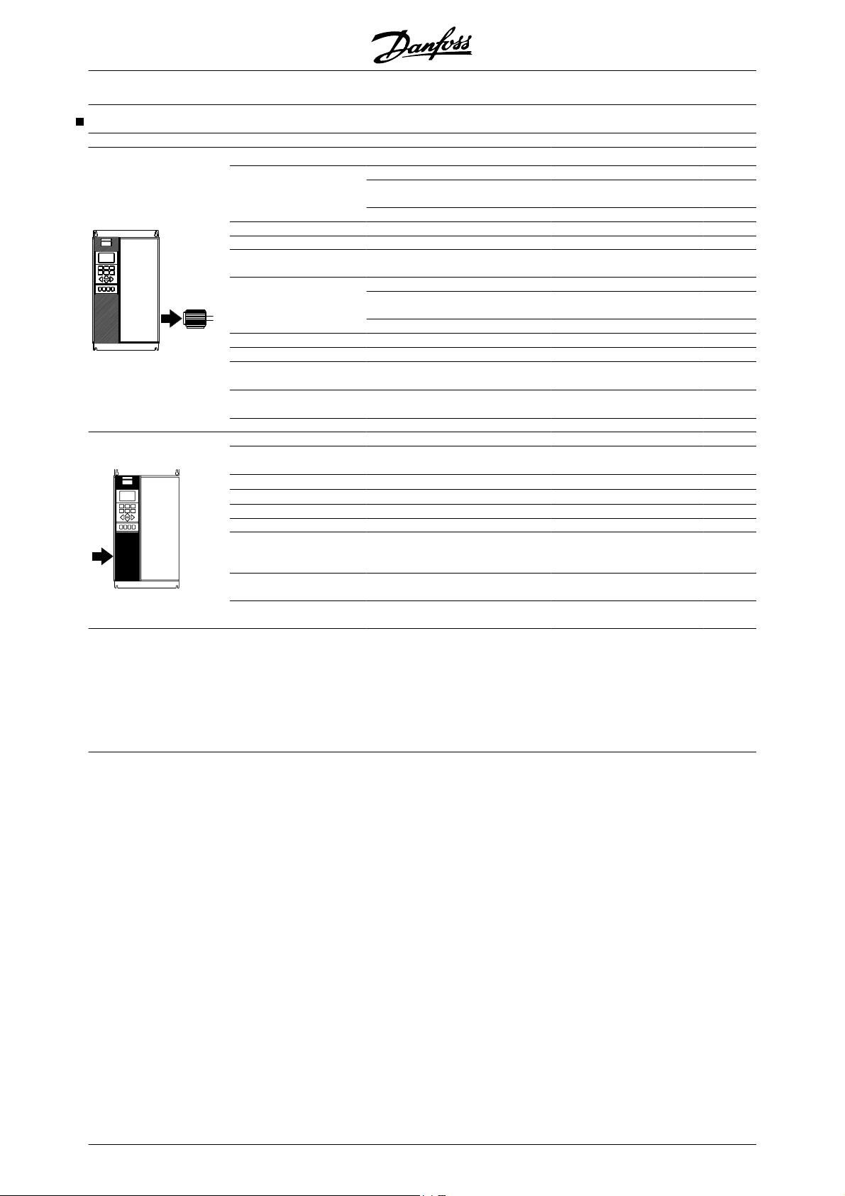
®
VLT
5000 Design Guide
Compact, Mains supply 3 x 200 - 240 V
According to international requirements VLT type 5008 5011 5016 5022 5027
Normal overload torque (110 %):
I
[A]
Output current
Output (240 V) S
Typical shaft output
Typical shaft output
I
VLT, MAX
VLT,N
P
P
VLT,N
VLT,N
VLT,N
High overload torque (160 %):
Output current
Output (240 V) S
Typical shaft output
Typical shaft output
Max. cable cross-section to motor, IP 54 16/6 16/6 35/2 35/2 50/0
brake and loadsharing [mm
Min. cable cross-section to motor, brake and
loadsharing
4)
[mm2 /AWG]
2)
Rated input current
Max. cable cross-section, IP 54 16/6 16/6 35/2 35/2 50/0
power [mm
2
]/[AWG]2)
5)
Max. pre-fuses
Efficiency
3)
I
VLT, MAX
VLT,N
P
P
2
/AWG]2)
(200 V) I
[-]/UL1) [A]
I
VLT,N
VLT,N
VLT,N
Weight IP 20 EB [kg] 21 25 27 34 36
Weight IP 54 [kg] 38 40 53 55 56
Power loss at max. load.
- high overload torque
[W]
(160 %)
- normal overload torque
[W]
(110 %)
Enclosure
32 46 61.2 73 88
(60 s)
35.2 50.6 67.3 80.3 96.8
[A]
[kVA]
13.3 19.1 25.4 30.3 36.6
[kW]
7.5 11 15 18.5 22
[HP]
10 15 20 25 30
[A]
25 32 46 61.2 73
(60 s)
40 51.2 73.6 97.9 116.8
[A]
[kVA]
10 13 19 25 30
[kW]
5.5 7.5 11 15 18.5
[HP]
7.5 10 15 20 25
5)
IP 20 16/6 35/2 35/2 35/2 50/0
10/8 10/8 10/8 10/8 16/6
[A]
32 46 61 73 88
L,N
IP 20 16/6 35/2 35/2 35/2 50/0
50 60 80 125 125
0.95 0.95 0.95 0.95 0.95
340 426 626 833 994
426 545 783 1042 1243
IP 20/
IP 54
IP 20/
IP 54
IP 20/
IP 54
IP 20/
IP 54
IP 20/
IP 54
1. For type of fuse see section Fuses
2. American Wire Gauge.
3. Measured using 30 m screened motor cables at rated load and rated frequency.
4. Min. cable cross-section is the smallest cable cross-section allowed to be fitted on the terminals to comply with IP 20. Always comply
with national and local regulations on min. cable cross-section.
5. Aluminium cables with cross-section above 35 mm
2
must be connected by use of a AI-Cu connector.
38 MG.52.B2.02 - VLT
®
is a registered Danfoss trademark
Page 40
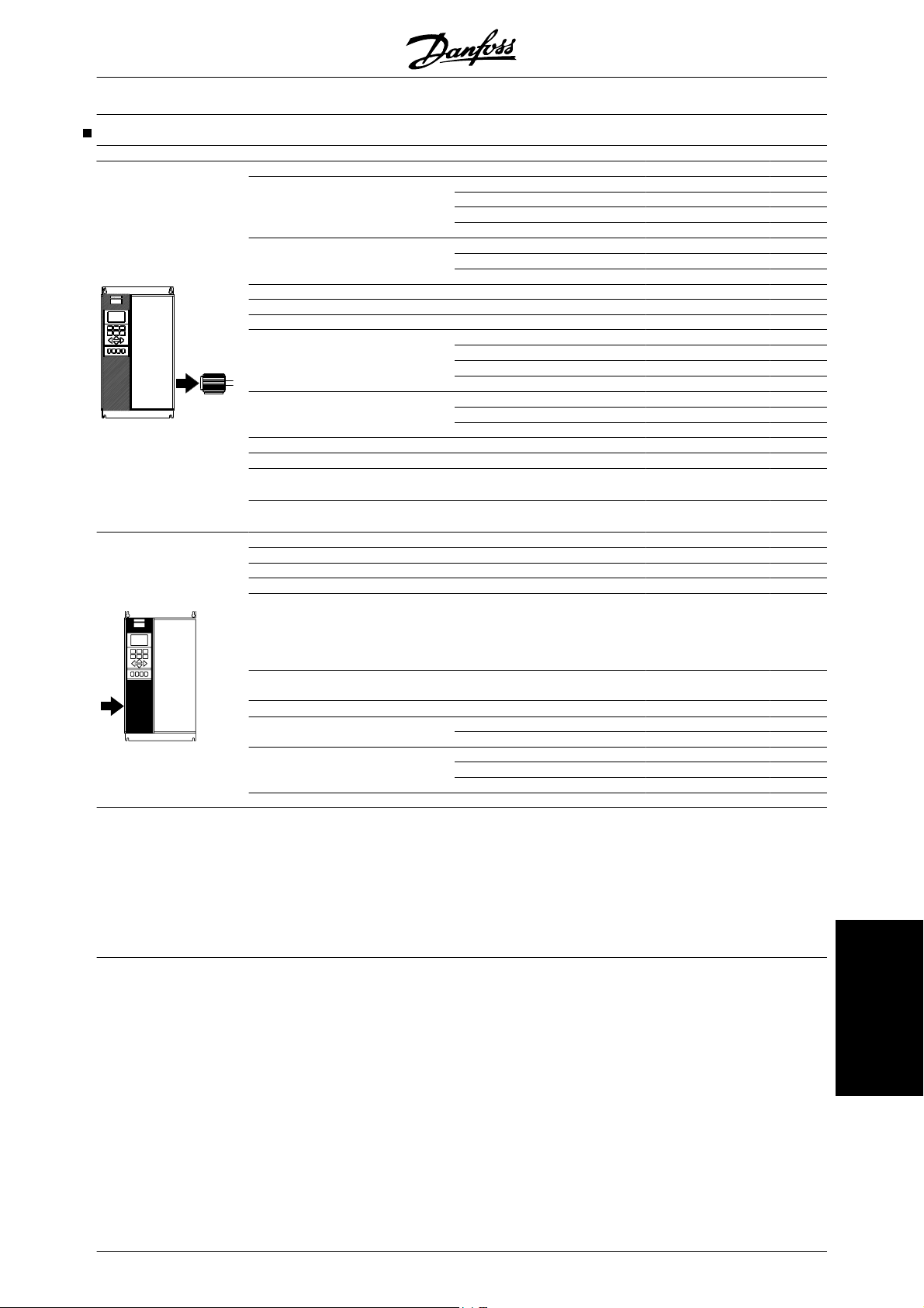
®
VLT
5000 Design Guide
Compact, Mains supply 3 x 200 - 240 V
According to international requirements VLT type 5032 5042 5052
Normal overload torque (110 %):
Output current
I
Output
S
(60 s) [A] (200-230 V)
I
VLT, MAX
[A] (231-240 V)
I
VLT,N
(60 s) [A] (231-240 V)
VLT, MAX
[kVA] (208 V)
S
VLT,N
[kVA] (230 V)
S
VLT,N
[kVA] (240 V)
VLT,N
[A] (200-230 V)
VLT,N
115 143 170
127 158 187
104 130 154
115 143 170
41 52 61
46 57 68
43 54 64
I
Typical shaft output [HP] (208 V) 40 50 60
Typical shaft output [kW] (230 V) 30 37 45
High overload torque (160 %):
Output current
I
Output
S
I
[A] (200-230 V)
VLT,N
[A] (200-230 V)
I
VLT, MAX
[A] (231-240 V)
I
VLT,N
[A] (231-240 V)
VLT, MAX
[kVA] (208 V)
S
VLT,N
S
[kVA] (230 V)
VLT,N
[kVA] (240 V)
VLT,N
88 115 143
132 173 215
80 104 130
120 285 195
32 41 52
35 46 57
33 43 54
Typical shaft output [HP] (208 V) 30 40 50
[kW] (230 V) 22 30 37
Max. cable cross-section to motor
and loadsharing
Max. cable cross-section to brake
Normal overload torque (110 %):
Rated input current
Normal overload torque (150 %):
Rated input current
Max. cable cross-section
power supply
Min. cable cross-section to motor,
power
[mm2 ]
[AWG]
[mm2 ]
[AWG]
I
[A] (230 V)
L,N
4,6
[mm2]
[AWG]
4,6
[mm2]
[AWG]
4,6
2,4,6
4,6
2,4,6
2,4,6
2,4,6
I
[A] (230 V)
L,N
120
300 mcm
25
4
101.3 126.6 149.9
77,9 101,3 126,6
120
300 mcm
6
8
supply, brake and loadsharing
Max. pre-fuses (mains) [-]/UL
Efficiency
3
Power loss
1
[A]
Normal overload [W]
150/15
200/200 250/250
0
0,96-0,97
1089 1361 1612
High overload [W] 838 1089 1361
Weight
Weight
Weight
IP 00 [kg]
IP 20 Nema1 [kg]
IP 54 Nema12 [kg] 104 104 104
101 101 101
101 101 101
Enclosure IP 00 / Nema 1 (IP 20) / IP 54
1. For type of fuse see section Fuses
2. American Wire Gauge.
3. Measured using 30 m screened motor cables at rated load and rated frequency.
4. Max. cable cross-section is the maximum possible cable cross-section allowed to be fitted on the terminals. Min. cable cross-section
is the minimum allowed cross-section. Always comply with national and local regulations on min. cable cross-section.
5. Weight without shipping container.
6. Connection stud: M8 Brake: M6.
MG.52.B2.02 - VLT
®
is a registered Danfoss trademark 39
Technical data
Page 41
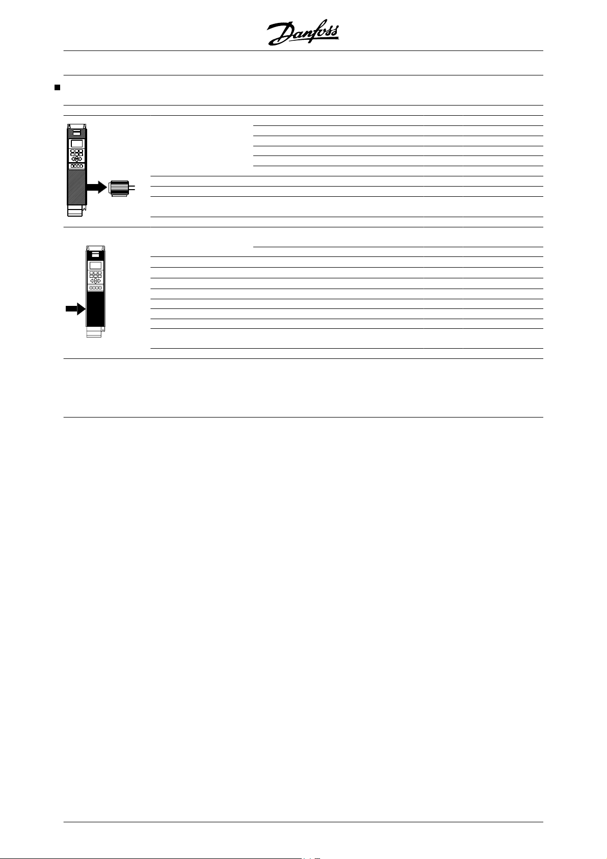
Bookstyle and Compact, Mains supply 3 x 380 - 500 V
VLT
®
5000 Design Guide
According to international requirements VLT type 5001 5002 5003 5004
I
Output current
I
VLT, MAX
I
VLT, MAX
Output
S
Typical shaft output
Typical shaft output
Max. cable cross-section to motor,
brake and loadsharing [mm
2
]/[AWG]2 )
S
[A] (380-415 V)
VLT,N
(60 s) [A] (380-415 V)
[A] (440-500 V)
I
VLT,N
(60 s) [A] (440-500 V)
[kVA] (380-415 V)
VLT,N
[kVA] (440-500 V)
VLT,N
P
P
VLT,N
VLT,N
[kW]
[HP]
2.2 2.8 4.1 5.6
3.5 4.5 6.5 9
1.9 2.6 3.4 4.8
3 4.2 5.5 7.7
1.7 2.1 3.1 4.3
1.6 2.3 2.9 4.2
0.75 1.1 1.5 2.2
1 1.5 2 3
4/10
4/10 4/10 4/10
Rated input current
I
Max. cable cross-section, power [mm2 ]/[AWG]
Max. pre-fuses [-]/UL1) [A]
Efficiency
3)
2)
I
L,N
[A] (460 V)
L,N
2.3 2.6 3.8 5.3
1.9 2.5 3.4 4.8
4/10 4/10 4/10 4/10
16/6 16/6 16/10 16/10
0.96 0.96 0.96 0.96
[A] (380 V)
Weight IP 20 EB Bookstyle [kg] 7 7 7 7.5
Weight IP 20 EB Compact [kg] 8 8 8 8.5
Weight IP 54 Compact [kg] 11.5 11.5 11.5 12
Power loss at max. load [W] 55 67 92 110
Enclosure
IP 20/
IP 54
IP 20/
IP 54
IP 20/
IP 54
IP 20/
IP 54
1. For type of fuse see section Fuses.
2. American Wire Gauge.
3. Measured using 30 m screened motor cables at rated load and rated frequency.
40 MG.52.B2.02 - VLT
®
is a registered Danfoss trademark
Page 42

Bookstyle and Compact, Mains supply 3 x 380 - 500 V
VLT
®
5000 Design Guide
According to international requirements VLT type 5005 5006 5008 5011
Output current
I
VLT, MAX
I
VLT, MAX
Output
S
Typical shaft output
Typical shaft output
Max. cable cross-section to motor,
brake and loadsharing [mm
2
]/[AWG]2 )
[A] (380-415 V)
VLT,N
(60 s) [A] (380-415 V)
[A] (440-500 V)
I
VLT,N
(60 s) [A] (440-500 V)
[kVA] (380-415 V)
S
VLT,N
[kVA] (440-500 V)
VLT,N
P
P
VLT,N
VLT,N
[kW]
[HP]
7.2 10 13 16
11.5 16 20.8 25.6
6.3 8.2 11 14.5
10.1 13.1 17.6 23.2
5.5 7.6 9.9 12.2
5.5 7.1 9.5 12.6
3.0 4.0 5.5 7.5
4 5 7.5 10
4/10
4/10 4/10 4/10
I
Rated input current
I
Max. cable cross-section power [mm2 ]/[AWG]
Max. pre-fuses [-]/UL1) [A]
Efficiency
3)
I
L,N
L,N
2)
[A] (460 V)
7 9.1 12.2 15.0
6 8.3 10.6 14.0
4/10 4/10 4/10 4/10
16/15 25/20 25/25 35/30
0.96 0.96 0.96 0.96
[A] (380 V)
Weight IP 20 EB Bookstyle [kg] 7.5 9.5 9.5 9.5
Weight IP 20 EB Compact [kg] 8.5 10.5 10.5 10.5
Weight IP 54 EB Compact [kg] 12 14 14 14
Power loss at max. load. [W] 139 198 250 295
Enclosure
IP 20/
IP 54
IP 20/
IP 54
IP 20/
IP 54
IP 20/
IP 54
1. For type of fuse see section Fuses.
2. American Wire Gauge.
3. Measured using 30 m screened motor cables at rated load and rated frequency.
MG.52.B2.02 - VLT
®
is a registered Danfoss trademark 41
Technical data
Page 43

®
VLT
5000 Design Guide
Compact, Mains supply 3 x 380 - 500 V
According to international requirements VLT type 5016 5022 5027
Normal overload torque (110 %):
Output current
Output
Typical shaft output
Typical shaft output
VLT,N
I
(60 s) [A] (380-415 V)
VLT, MAX
I
VLT, MAX
I
VLT,N
(60 s) [A] (440-500 V)
[kVA] (380-415 V)
S
VLT,N
S
[kVA] (440-500 V)
VLT,N
[A] (380-415 V)
[A] (440-500 V)
P
VLT,N
P
VLT,N
32 37.5 44
35.2 41.3 48.4
27.9 34 41.4
30.7 37.4 45.5
24.4 28.6 33.5
[kW]
15 18.5 22
[HP]
20 25 30
24.2 29.4 35.8
I
High overload torque (160 %):
I
Output current
I
VLT, MAX
I
VLT, MAX
Output
S
S
Typical shaft output
Typical shaft output
Max. cable cross-section to motor, IP 54 16/6 16/6 16/6
brake and loadsharing [mm
Min. cable cross-section to motor,
brake and loadsharing [mm2]/[AWG]
2
]/[AWG]
2)
2) 4)
Rated input current
I
Max. cable cross-section, IP 54 16/6 16/6 16/6
power [mm
2
]/[AWG]
Max. pre-fuses
Efficiency
3)
[A] (380-415 V)
VLT,N
(60 s) [A] (380-415 V)
I
[A] (440-500 V)
VLT,N
(60 s) [A] (440-500 V)
[kVA] (380-415 V)
VLT,N
[kVA] (440-500 V)
VLT,N
P
VLT,N
P
VLT,N
I
[A] (380 V)
L,N
[A] (460 V)
L,N
[-]/UL1) [A]
24 32 37.5
38.4 51.2 60
21.7 27.9 34
34.7 44.6 54.4
18.3 24.4 28.6
[kW]
11 15 18.5
[HP]
15 20 25
18.8 24.2 29.4
IP 20 16/6 16/6 35/2
10/8 10/8 10/8
32 37.5 44
27.6 34 41
IP 20
16/6 16/6 35/2
63/40 63/50 63/60
0.96 0.96 0.96
Weight IP 20 EB [kg] 21 22 27
Weight IP 54 [kg] 41 41 42
Power loss at max. load.
- high overload torque (160 %)
[W] 419 559 655
- normal overload torque (110 %) [W] 559 655 768
Enclosure
IP 20/
IP 54
IP 20/
IP 54
IP 20/
IP 54
1. For type of fuse see section Fuses.
2. American Wire Gauge.
3. Measured using 30 m screened motor cables at rated load and rated frequency.
4. Min. cable cross-section is the smallest cable cross-section allowed to be fitted on the terminals to comply with IP 20. Always comply
with national and local regulations on min. cable cross-section.
42 MG.52.B2.02 - VLT
®
is a registered Danfoss trademark
Page 44

®
VLT
5000 Design Guide
Compact, Mains supply 3 x 380 - 500 V
According to international requirements VLT type 5032 5042 5052
Normal overload torque (110 %):
I
Output current
Output
Typical shaft output
Typical shaft output
I
VLT, MAX
I
VLT, MAX
S
S
[A] (380-415 V)
VLT,N
(60 s) [A] (380-415 V)
I
[A] (440-500 V)
VLT,N
(60 s) [A] (440-500 V)
[kVA] (380-415 V)
VLT,N
[kVA] (440-500 V)
VLT,N
P
P
VLT,N
VLT,N
High overload torque (160 %):
I
Output current
I
VLT, MAX
I
VLT, MAX
Output
S
S
Typical shaft output
Typical shaft output
Max. cable cross-section to motor, IP 54 35/2 35/2 50/0
brake and loadsharing [mm
Min. cable cross-section to motor,
brake and loadsharing [mm
2
]/[AWG]2)
2
]/[AWG]2)
Rated input current
Max. cable cross-section IP 54 35/2 35/2 50/0
power[mm
2
]/[AWG]
2) 5)
Max. pre-fuses
Efficiency
3)
[A] (380-415 V)
VLT,N
(60 s) [A] (380-415 V)
I
[A] (440-500 V)
VLT,N
(60 s) [A] (440-500 V)
[kVA] (380-415 V)
VLT,N
[kVA] (440-500 V)
VLT,N
5)
4)
P
VLT,N
P
VLT,N
I
[A] (380 V)
L,N
I
[A] (460 V)
L,N
[-]/UL1) [A]
Weight IP 20 EB [kg] 28 41 42
Weight IP 54 [kg] 54 56 56
Power loss at max. load.
- high overload torque (160 %)
- normal overload torque (110 %) [W] 1065 1275 1571
Enclosure
61 73 90
67.1 80.3 99
54 65 78
59.4 71.5 85.8
46.5 55.6 68.6
[kW]
30 37 45
[HP]
40 50 60
46.8 56.3 67.5
44 61 73
70.4 97.6 116.8
41.4 54 65
66.2 86 104
33.5 46.5 55.6
[kW]
22 30 37
[HP]
30 40 50
35.9 46.8 56.3
IP20 35/2 35/2 50/0
10/8 10/8 16/6
60 72 89
53 64 77
IP 20 35/2 35/2 50/0
80/80 100/100 125/125
0.96 0.96 0.96
[W] 768 1065 1275
IP 20/
IP 54
IP 20/
IP 54
IP 20/
IP 54
1. For type of fuse see section Fuses.
2. American Wire Gauge.
3. Measured using 30 m screened motor cables at rated load and rated frequency.
4. Min. cable cross-section is the smallest cable cross-section allowed to be fitted on the terminals to comply with IP 20. Always comply
with national and local regulations on min. cable cross-section.
5. Aluminium cables with cross-section above 35 mm
2
must be connected by use of a AI-Cu connector.
Technical data
MG.52.B2.02 - VLT
®
is a registered Danfoss trademark 43
Page 45

®
VLT
5000 Design Guide
Compact, Mains supply 3 x 380 - 500 V
According to international requirements VLT type 5062 5072 5102
Normal overload torque (110 %):
Output current
Output
Typical shaft output
VLT,N
I
(60 s) [A] (380-415 V)
VLT, MAX
I
I
VLT, MAX
VLT,N
(60 s) [A] (440-500 V)
[kVA] (380-415 V)
S
VLT,N
S
[kVA] (440-500 V)
VLT,N
P
P
P
[A] (380-415 V)
[A] (440-500 V)
[kW] (400 V)
VLT,N
[HP] (460 V)
VLT,N
[kW] (500 V)
VLT,N
106 147 177
117 162 195
106 130 160
117 143 176
80.8 102 123
91.8 113 139
55 75 90
75 100 125
75 90 110
I
High overload torque (160 %):
I
Output current
I
VLT, MAX
I
VLT, MAX
Output
S
S
Typical shaft output
Max. cable cross-section to motor, IP 54
brake and loadsharing [mm2 ]/[AWG]
Min. cable cross-section to motor,
brake and loadsharing [mm
2
]/[AWG]
2)
4)
Rated input current
I
Max. cable cross-section IP 54
power[mm
2
]/[AWG]
2)
Max. pre-fuses
Efficiency
3)
[A] (380-415 V)
VLT,N
(60 s) [A] (380-415 V)
I
[A] (440-500 V)
VLT,N
(60 s) [A] (440-500 V)
[kVA] (380-415 V)
VLT,N
[kVA] (440-500 V)
VLT,N
P
[kW] (400 V)
VLT,N
[HP] (460 V)
P
VLT,N
P
[kW] (500 V)
VLT,N
I
[A] (380 V)
L,N
[A] (460 V)
L,N
[-]/UL1) [A]
90 106 147
135 159 221
80 106 130
120 159 195
68.6 73.0 102
69.3 92.0 113
45 55 75
60 75 100
55 75 90
IP20
50/0
50/0
150/300
5)
mcm
120/250
5)
mcm
6)
5)
150/300
mcm
120/250
mcm
16/6 25/4 25/4
104 145 174
104 128 158
IP 20
50/0
50/0
5)
5)
150/300
mcm
120/250
mcm
5)
150/300
mcm
120/250
mcm
160/150 225/225 250/250
>0.97 >0.97 >0.97
Weight IP 20 EB [kg] 43 54 54
Weight IP 54 [kg] 60 77 77
Power loss at max. load.
- high overload torque (160 %)
[W] 1122 1058 1467
- normal overload torque (110 %) [W] 1322 1467 1766
Enclosure
IP20/
IP 54
IP20/
IP 54
IP20/
IP 54
6)
5)
5)
1. For type of fuse see section Fuses.
2. American Wire Gauge.
3. Measured using 30 m screened motor cables at rated load and rated frequency.
4. Min. cable cross-section is the smallest cable cross-section allowed to be fitted on the terminals to comply with IP 20. Always comply
with national and local regulations on min. cable cross-section.
5. Aluminium cables with cross-section above 35 mm
used.
6. Brake and loadsharing: 95 mm
2
/ AWG 3/0
44 MG.52.B2.02 - VLT
2
must be connected by use of a AI-Cu connector.
®
is a registered Danfoss trademark
Page 46

®
VLT
5000 Design Guide
Compact, Mains supply 3 x 380 - 500 V
According to international requirements VLT type 5122 5152 5202 5252 5302
Normal overload current (110 %):
I
Output current
I
VLT, MAX
I
VLT, MAX
Output
S
Typical shaft output
[A] (380-415 V)
VLT,N
(60 s) [A] (380-415
[A] (440-500 V)
I
VLT,N
(60 s) [A] (440-500
[kVA] (400 V)
S
VLT,N
[kVA] (460 V)
S
VLT,N
[kVA] (500 V)
VLT,N
[kW] (400 V)
[HP] (460 V) 150 200 250 300 350
[kW] (500 V) 132 160 200 250 315
High overload torque (160 %):
I
Output current
I
VLT, MAX
I
VLT, MAX
Output
S
Typical shaft output
[A] (380-415 V)
VLT,N
(60 s) [A] (380-415
[A] (441-500 V)
I
VLT,N
(60 s) [A] (440-500
[kVA] (400 V)
S
VLT,N
[kVA] (460 V)
S
VLT,N
[kVA] (500 V)
VLT,N
[kW] (400 V)
[HP] (460 V) 125 150 200 250 300
Max. cable cross-section to
motor
Max. cable cross-section to
loadsharing and brake
[kW] (500 V) 110 132 160 200 250
[mm2]
[AWG]
[mm2]
[AWG]
Normal overload current (110 %):
I
Rated input current
I
[A] (380-415 V)
L,N
[A] (440-500 V)
L,N
High overload torque (160 %):
I
Rated input current
I
Max. cable cross-section
power supply
[A] (380-415 V)
L,N
[A] (440-500 V)
L,N
[mm2]
[AWG]
Max. pre-fuses (mains) [-]/
UL
Efficiency
Power loss
Weight
Weight
Weight
3
Normal overload [W]
High overload [W] 2206 2619 3309 4163 4977
IP 00 [kg]
IP 21/Nema1 [kg]
IP 54/Nema12 [kg] 96 104 125 136 151
Enclosure IP 00, IP 21/Nema 1 and IP 54/Nema12
212 260 315 395 480
233 286 347 434 528
V)
190 240 302 361 443
209 264 332 397 487
V)
147 180 218 274 333
151 191 241 288 353
165 208 262 313 384
110 132 160 200 250
177 212 260 315 395
266 318 390 473 593
V)
160 190 240 302 361
240 285 360 453 542
V)
123 147 180 218 274
127 151 191 241 288
139 165 208 262 313
90 110 132 160 200
4,6
2,4,6
4,6
2,4,6
2 x 70
2 x 2/0
2 x 70
2 x 2/0
2 x 185
2 x 350 mcm
2 x 185
2 x 350 mcm
208 256 317 385 467
185 236 304 356 431
174 206 256 318 389
158 185 236 304 356
4,6
2,4,6
[A]
2 x 70
2 x 2/0
300/
1
300
350/
350
450/
400
2 x 185
2 x 350 mcm
500/
500
0,98
2619 3309 4163 4977 6107
82 91 112 123 138
96 104 125 136 151
630/
600
1. For type of fuse see section Fuses
2. American Wire Gauge.
3. Measured using 30 m screened motor cables at rated load and rated frequency.
4. Max. cable cross-section is the maximum possible cable cross-section allowed to be fitted on the terminals. Always comply with
national and local regulations on min. cable cross-section.
5. Weight without shipping container.
6. Connection bolt power supply and motor: M10; Brake and loadsharing: M8
MG.52.B2.02 - VLT
®
is a registered Danfoss trademark 45
Technical data
Page 47

®
VLT
5000 Design Guide
Compact, Mains supply 3 x 380 - 500 V
According to international requirements VLT type 5352 5452 5502 5552
Normal overload current (110 %):
I
Output current
I
VLT, MAX
I
VLT, MAX
Output S
Typical shaft output
[A] (380-415 V)
VLT,N
(60 s) [A] (380-415
[A] (440-500 V)
I
VLT,N
(60 s) [A] (440-500
[kVA] (400 V)
VLT,N
[kVA] (460 V)
S
VLT,N
[kVA] (500 V)
S
VLT,N
[kW] (400 V) 315 355 400 450
[HP] (460 V)
[kW] (500 V) 355 400 500 530
High overload torque (160 %):
I
Output current
I
VLT, MAX
I
VLT, MAX
Output S
Typical shaft output
Max. cable cross-section
to motor and loadsharing
Max. cable cross-section
to brake
[A] (380-415 V)
VLT,N
(60 s) [A] (380-415
[A] (440-500 V)
I
VLT,N
(60 s) [A] (440-500
[kVA] (400 V)
VLT,N
[kVA] (460 V)
S
VLT,N
[kVA] (500 V)
S
VLT,N
[kW] (400 V) 250 315 355 400
[HP] (460 V)
[kW] (500 V) 315 355 400 500
[mm2]
[AWG]
[mm2]
[AWG]
Normal overload current (110 %):
I
Rated input current
I
[A] (380-415 V)
L,N
[A] (440-500 V)
L,N
High overload torque (160 %):
I
Rated input current
I
Max. cable cross-section
power supply
[A] (380-415 V)
L,N
[A] (440-500 V)
L,N
[mm2]
[AWG]
Max. pre-fuses (mains)
[-]/UL
Efficiency
Power loss
Weight
Weight
Weight
3
Normal overload [W]
High overload [W] 6005 6960 7691 7964
IP 00 [kg]
IP 21/Nema1 [kg]
IP 54/Nema12 [kg] 263 270 272 313
Enclosure IP 00, IP 21/Nema 1 and IP 54/Nema12
600 658 745 800
660 724 820 880
V)
540 590 678 730
594 649 746 803
V)
416 456 516 554
430 470 540 582
468 511 587 632
450 500 550/600 600
480 600 658 695
720 900 987 1042
V)
443 540 590 678
665 810 885 1017
V)
333 416 456 482
353 430 470 540
384 468 511 587
350 450 500 550
4,6
2,4,6
4,6
2,4,6
4x240
4x500 mcm
2x185
2x350 mcm
590 647 733 787
531 580 667 718
472 590 647 684
436 531 580 667
4,6
4x240
2,4,6
4x500 mcm
1
700/700 900/900 900/900 900/900
[A]
0,98
7630 7701 8879 9428
221 234 236 277
263 270 272 313
1. For type of fuse see section Fuses
2. American Wire Gauge.
3. Measured using 30 m screened motor cables at rated load and rated frequency.
4. Max. cable cross-section is the maximum possible cable cross-section allowed to be fitted on the terminals. Always comply with
national and local regulations on min. cable cross-section.
5. Weight without shipping container.
6. Connection bolt power supply, motor and loadsharing: M10 (compression lug), 2xM8 (box lug), M8 (brake)
46 MG.52.B2.02 - VLT
®
is a registered Danfoss trademark
Page 48

®
VLT
5000 Design Guide
Compact, Mains supply 3 x 525 - 600 V
According to international requirements VLT type 5001 5002 5003 5004
Normal overload torque (110 %):
I
Output current
I
VLT, MAX
I
VLT, MAX
Output S
Typical shaft output
Typical shaft output
Highl overload torque (160%):
Output current
I
VLT, MAX
I
VLT, MAX
Output
Typical shaft output
Typical shaft output
Max. cable cross-section to motor,
brake and loadsharing [mm
2
]/[AWG]
2)
S
S
S
[A] (550 V)
VLT,N
(60 s) [A] (550 V)
[A] (575 V)
I
VLT,N
(60 s) [A] (575 V)
[kVA] (550 V)
VLT,N
[kVA] (575 V)
VLT,N
P
[kW]
VLT,N
P
[HP]
VLT,N
I
[A] (550 V)
VLT,N
(60 s) [A] (550 V)
I
[A] (575 V)
VLT,N
(60 s) [A] (575 V)
[kVA] (550 V)
VLT,N
[kVA] (575 V)
VLT,N
P
[kW]
VLT,N
P
[HP]
VLT,N
2.6 2.9 4.1 5.2
2.9 3.2 4.5 5.7
2.4 2.7 3.9 4.9
2.6 3.0 4.3 5.4
2.5 2.8 3.9 5.0
2.4 2.7 3.9 4.9
1.1 1.5 2.2 3
1.5 2 3 4
1.8 2.6 2.9 4.1
2.9 4.2 4.6 6.6
1.7 2.4 2.7 3.9
2.7 3.8 4.3 6.2
1.7 2.5 2.8 3.9
1.7 2.4 2.7 3.9
0.75 1.1 1.5 2.2
1 1.5 2 3
4/10 4/10 4/10 4/10
Normal overload torque (110 %):
Rated input current
[A] (550 V)
I
L,N
I
[A] (600 V)
L,N
High overload torque ( 160 %):
I
Rated input current
I
Max. cable cross-section, power [mm2 ]/[AWG]
Max. pre-fuses
Efficiency
3)
[A] (550 V)
L,N
[A] (600 V)
L,N
2)
[-]/UL1) [A]
2.5 2.8 4.0 5.1
2.2 2.5 3.6 4.6
1.8 2.5 2.8 4.0
1.6 2.2 2.5 3.6
4/10 4/10 4/10 4/10
3 4 5 6
0.96 0.96 0.96 0.96
Weight IP 20 EB [kg] 10.5 10.5 10.5 10.5
Power loss at max.
load.
[W] 63 71 102 129
Enclosure IP 20 / Nema 1
1. For type of fuses see section Fuses.
2. American Wire Gauge.
3. Measured using 30 m screened motor cables at rated load and rated frequency.
Technical data
MG.52.B2.02 - VLT
®
is a registered Danfoss trademark 47
Page 49

®
VLT
5000 Design Guide
Compact, Mains supply 3 x 525 - 600 V
According to international requirements VLT type 5005 5006 5008 5011
Normal overload torque (110 %):
I
Output current
I
VLT, MAX
I
VLT, MAX
Output S
Typical shaft output
Typical shaft output
Highl overload torque (160%):
Output current
I
VLT, MAX
I
VLT, MAX
Output
Typical shaft output
Typical shaft output
Max. cable cross-section to motor,
brake and loadsharing [mm
2
]/[AWG]
2)
S
S
S
[A] (550 V)
VLT,N
(60 s) [A] (550 V)
[A] (575 V)
I
VLT,N
(60 s) [A] (575 V)
[kVA] (550 V)
VLT,N
[kVA] (575 V)
VLT,N
P
[kW]
VLT,N
P
[HP]
VLT,N
I
[A] (550 V)
VLT,N
(60 s) [A] (550 V)
I
[A] (575 V)
VLT,N
(60 s) [A] (575 V)
[kVA] (550 V)
VLT,N
[kVA] (575 V)
VLT,N
P
[kW]
VLT,N
P
[HP]
VLT,N
6.4 9.5 11.5 11.5
7.0 10.5 12.7 12.7
6.1 9.0 11.0 11.0
6.7 9.9 12.1 12.1
6.1 9.0 11.0 11.0
6.1 9.0 11.0 11.0
4 5.5 7.5 7.5
5 7.5 10.0 10.0
5.2 6.4 9.5 11.5
8.3 10.2 15.2 18.4
4.9 6.1 9.0 11.0
7.8 9.8 14.4 17.6
5.0 6.1 9.0 11.0
4.9 6.1 9.0 11.0
3 4 5.5 7.5
4 5 7.5 10
4/10 4/10 4/10 4/10
Normal overload torque (110 %):
Rated input current
I
[A] (550 V)
I
L,N
[A] (600 V)
L,N
High overload torque ( 160 %):
I
Rated input current
I
Max. cable cross-section, power [mm2 ]/[AWG]
Max. pre-fuses
Efficiency
3)
[A] (550 V)
L,N
[A] (600 V)
L,N
2)
[-]/UL1) [A]
6.2 9.2 11.2 11.2
5.7 8.4 10.3 10.3
5.1 6.2 9.2 11.2
4.6 5.7 8.4 10.3
4/10 4/10 4/10 4/10
8 10 15 20
0.96 0.96 0.96 0.96
Weight IP 20 EB [kg] 10.5 10.5 10.5 10.5
Power loss at max.
load.
[W] 160 236 288 288
Enclosure IP 20 / Nema 1
1. For type of fuses see section Fuses.
2. American Wire Gauge.
3. Measured using 30 m screened motor cables at rated load and rated frequency.
48 MG.52.B2.02 - VLT
®
is a registered Danfoss trademark
Page 50
®
VLT
5000 Design Guide
Compact, Mains supply 3 x 525 - 600 V
According to international requirements VLT type 5016 5022 5027
Normal overload torque (110 %):
Output current
Output
Typical shaft output
Typical shaft output
I
VLT, MAX
I
VLT, MAX
S
S
VLT,N
VLT,N
[A] (550 V)
VLT,N
(60 s) [A] (550 V)
I
[A] (575 V)
VLT,N
(60 s) [A] (575 V)
[kVA] (550 V)
[kVA] (575 V)
P
[kW]
VLT,N
P
[HP]
VLT,N
23 28 34
25
22
24
31 37
27 32
30 35
22 27 32
22
27 32
15 18.5 22
20 25 30
I
High overload torque (160 %):
I
Output current
I
VLT, MAX
I
VLT, MAX
Output
S
S
Typical shaft output
Typical shaft output
Max. cable cross-section to motor, 16 16 35
brake and loadsharing [mm
Min. cable cross-section to motor, 0.5 0.5 10
brake and loadsharing [mm2]/[AWG]
2
]/[AWG]
2)
4)
[A] (550 V)
VLT,N
(60 s) [A] (550 V)
I
[A] (575 V)
VLT,N
(60 s) [A] (575 V)
[kVA] (550 V)
VLT,N
[kVA] (575 V)
VLT,N
P
[kW]
VLT,N
P
[HP]
VLT,N
Normal overload torque (110 %):
[A] (550 V)
Rated input current
I
I
L,N
[A] (600 V)
L,N
High overload torque (160 %):
[A] (550 V)
Rated input current
Max. cable cross-section, 16 16 35
power [mm
2
]/[AWG]
2)
Max. pre-fuses
Efficiency
3)
I
L,N
I
[A] (600 V)
L,N
[-]/UL1) [A]
18 23 28
29
17
27
37 45
22 27
35 43
17 22 27
17
22 27
11 15 18.5
15 20 25
6 6 2
20 20 8
22 27 33
21 25 30
18 22 27
16 21 25
6 6 2
30 35 45
0.96 0.96 0.96
Weight IP 20 EB [kg] 23 23 30
Power loss at max. load [W] 576 707 838
Enclosure IP 20 / Nema 1
1. For type of fuse see section Fuses
2. American Wire Gauge.
3. Measured using 30 m screened motor cables at rated load and rated frequency.
4. Min. cable cross-section is the smallest cable cross-section allowed to be fitted on the terminals to comply with IP 20. Always comply
with national and local regulations on min. cable cross-section.
Technical data
MG.52.B2.02 - VLT
®
is a registered Danfoss trademark 49
Page 51
®
VLT
5000 Design Guide
Compact, Mains supply 3 x 525 - 600 V
According to international requirements VLT type 5032 5042 5052 5062
Normal overload torque (110 %):
Output current
Output
Typical shaft output
Typical shaft output
I
(60 s) [A] (550 V)
VLT, MAX
I
(60 s) [A] (575 V)
VLT, MAX
S
VLT,N
S
VLT,N
[A] (550 V)
VLT,N
I
[A] (575 V)
VLT,N
[kVA] (550 V)
[kVA] (575 V)
P
VLT,N
P
VLT,N
[kW]
[HP]
43 54 65 81
47
41
45
59 72 89
52 62 77
57 68 85
41 51 62 77
41
52 62 77
30 37 45 55
40 50 60 75
I
High overload torque (160 %):
I
Output current
I
VLT, MAX
I
VLT, MAX
Output
S
S
Typical shaft output
Typical shaft output
Max. cable cross-section to motor, 35 50 50 50
brake and loadsharing [mm
Min. cable cross-section to motor, 10 16 16 16
brake and loadsharing [mm
2
]/[AWG]2)
2
]/[AWG]
4)
[A] (550 V)
VLT,N
(60 s) [A] (550 V)
I
[A] (575 V)
VLT,N
(60 s) [A] (575 V)
[kVA] (550 V)
VLT,N
[kVA] (575 V)
VLT,N
P
VLT,N
P
VLT,N
5)
[kW]
[HP]
Normal overload torque (110 %):
[A] (550 V)
Rated input current
I
I
L,N
[A] (600 V)
L,N
High overload torque (160 %):
I
Rated input current
I
Max. cable cross-section 35 50 50 50
power[mm
2
]/[AWG]
2) 5)
Max. pre-fuses
Efficiency
3)
[A] (550 V)
L,N
[A] (600 V)
L,N
[-]/UL1) [A]
34 43 54 65
54
32
51
69 86 104
41 52 62
66 83 99
32 41 51 62
32
41 52 62
22 30 37 45
30 40 50 60
2 1/0 1/0 1/0
8 6 6 6
42 53 63 79
38 49 58 72
33 42 53 63
30 38 49 58
2 1/0 1/0 1/0
60 75 90 100
0.96 0.96 0.96 0.96
Weight IP 20 EB [kg] 30 48 48 48
Power loss at max. load [W] 1074 1362 1624 2016
Enclosure IP 20 / Nema 1
1. For type of fuse see section Fuses
2. American Wire Gauge.
3. Measured using 30 m screened motor cables at rated load and rated frequency.
4. Min. cable cross-section is the smallest cable cross-section allowed to be fitted on the terminals to comply with IP 20. Always comply
with national and local regulations on min. cable cross-section.
5. Aluminium cables with cross-section above 35 mm
2
must be connected by use of a AI-Cu connector.
50 MG.52.B2.02 - VLT
®
is a registered Danfoss trademark
Page 52
®
VLT
5000 Design Guide
Mains supply 3 x 525 - 690 V
According to international requirements VLT type 5042 5052 5062 5072 5102
Normal overload torque (110 %):
I
Output current
I
VLT, MAX
I
VLT, MAX
Output
S
Typical shaft output
[A] (525-550 V)
VLT,N
(60 s) [A] (525-550
[A] (551-690 V)
I
VLT,N
(60 s) [A] (551-690
[kVA] (550 V)
S
VLT,N
[kVA] (575 V)
S
VLT,N
[kVA] (690 V)
VLT,N
[kW] (550 V)
[HP] (575 V) 50 60 75 100 125
[kW] (690 V) 45 55 75 90 110
High overload torque (160 %):
I
Output current
I
VLT, MAX
I
VLT, MAX
Output
S
Typical shaft output
[A] (525-550 V)
VLT,N
(60 s) [A] (525-550
[A] (551-690 V)
I
VLT,N
(60 s) [A] (551-690
[kVA] (550 V)
S
VLT,N
[kVA] (575 V)
S
VLT,N
[kVA] (690 V)
VLT,N
[kW] (550 V)
[HP] (575 V) 40 50 60 75 100
Max. cable cross-section
to motor
Max. cable cross-section
to loadsharing and brake
[kW] (690 V) 37 45 55 75 90
[mm2]
[AWG]
[mm2]
[AWG]
Normal overload torque (110 %):
I
Rated input current
I
[A] (550 V)
L,N
[A] (575 V)
I
L,N
[A] (690 V)
L,N
High overload torque (160 %):
I
Rated input current
I
Max. cable cross-section
power supply
[A] (550 V)
L,N
[A] (575 V)
I
L,N
[A] (690 V)
L,N
[AWG]
[mm2]
Max. pre-fuses (mains) [-]/
UL
Efficiency
Power loss
Weight
3
Normal overload [W]
High overload [W] 1355 1459 1721 1913 2264
IP 00 [kg]
Weight IP 21/Nema1 [kg] 96
Weight
IP 54/Nema12 [kg] 96
Enclosure IP 00, IP 21/Nema 1 and IP 54/Nema12
56 76 90 113 137
62 84 99 124 151
V)
54 73 86 108 131
59 80 95 119 144
V)
53 72 86 108 131
54 73 86 108 130
65 87 103 129 157
37 45 55 75 90
48 56 76 90 113
77 90 122 135 170
V)
46 54 73 86 108
74 86 117 129 162
V)
46 53 72 86 108
46 54 73 86 108
55 65 87 103 129
30 37 45 55 75
4,6
2,4,6
4,6
2,4,6
2 x 70
2 x 2/0
2 x 70
2 x 2/0
60 77 89 110 130
58 74 85 106 124
58 77 87 109 128
53 60 77 89 110
51 58 74 85 106
50 58 77 87 109
4,6
2,4,6
1
125 160 200 200 250
[A]
2 x 70
2 x 2/0
0.97 0.97 0.98 0.98 0.98
1458 1717 1913 2262 2662
82
1. For type of fuse see section Fuses
2. American Wire Gauge.
3. Measured using 30 m screened motor cables at rated load and rated frequency.
4. Max. cable cross-section is the maximum possible cable cross-section allowed to be fitted on the terminals. Always comply with national and local
regulations on min. cable cross-section.
5. Weight without shipping container.
6. Connection bolt power supply and motor: M10; Brake and loadsharing: M8
MG.52.B2.02 - VLT
®
is a registered Danfoss trademark 51
Technical data
Page 53

®
VLT
5000 Design Guide
mains supply 3 x 525 - 690 V
According to international requirements VLT type 5122 5152 5202 5252 5302 5352
Normal overload torque (110 %):
I
Output current
Output
S
Typical shaft output
[A] (525-550 V)
VLT,N
I
VLT, MAX
[A] (551-690 V)
I
VLT,N
I
VLT, MAX
[kVA] (550 V)
S
VLT,N
[kVA] (575 V)
S
VLT,N
[kVA] (690 V)
VLT,N
[kW] (550 V)
(60 s) [A]
(525-550 V)
(60 s) [A]
(551-690 V)
[HP] (575 V) 150 200 250 300 350 400
[kW] (690 V) 132 160 200 250 315 400
High overload torque (160 %):
I
Output current
Output
S
Typical shaft output
[A] (525-550 V)
VLT,N
I
VLT, MAX
[A] (551-690 V)
I
VLT,N
I
VLT, MAX
[kVA] (550 V)
S
VLT,N
[kVA] (575 V)
S
VLT,N
[kVA] (690 V)
VLT,N
[kW] (550 V)
(60 s) [A]
(525-550 V)
(60 s) [A]
(551-690 V)
[HP] (575 V) 125 150 200 250 300 350
Max. cable cross-section
to motor
Max. cable cross-section
to loadsharing and brake
[kW] (690 V) 110 132 160 200 250 315
[mm2]
[AWG]
[mm2]
[AWG]
Normal overload torque (110 %):
I
Rated input current
I
[A] (550 V)
L,N
[A] (575 V)
I
L,N
[A] (690 V)
L,N
High overload torque (160 %):
I
Rated input current
I
Max. cable cross-section
power supply
[A] (550 V)
L,N
[A] (575 V)
I
L,N
[A] (690 V)
L,N
[AWG]
[mm2]
Max. pre-fuses (mains)
[-]/UL
Efficiency
Power loss
Weight
3
Normal overload [W]
High overload [W] 2664 2952 3451 4275 4875 5185
IP 00 [kg]
Weight IP 21/Nema1 [kg] 96 104 125 136 151 165
Weight
IP 54/Nema12 [kg] 96 104 125 136 151 165
Enclosure IP 00, IP 21/Nema 1 and IP 54/Nema12
162 201 253 303 360 418
178 221 278 333 396 460
155 192 242 290 344 400
171 211 266 319 378 440
154 191 241 289 343 398
154 191 241 289 343 398
185 229 289 347 411 478
110 132 160 200 250 315
137 162 201 253 303 360
206 243 302 380 455 540
131 155 192 242 290 344
197 233 288 363 435 516
131 154 191 241 289 343
130 154 191 241 289 343
157 185 229 289 347 411
90 110 132 160 200 250
4,6
2,4,6
2,4,6
2 x 70
2 x 2/0
4,6
2 x 70
2 x 2/0
2 x 185
2 x 350 mcm
2 x 185
2 x 350 mcm
158 198 245 299 355 408
151 189 234 286 339 390
155 197 240 296 352 400
130 158 198 245 299 355
124 151 189 234 286 339
128 155 197 240 296 352
4,6
2,4,6
[A]
2 x 70
2 x 2/0
1
315 350 350 400 500 550
2 x 185
2 x 350 mcm
0,98
3114 3612 4292 5155 5821 6149
82 91 112 123 138 151
1. For type of fuse see section Fuses
2. American Wire Gauge.
3. Measured using 30 m screened motor cables at rated load and rated frequency.
4. Max. cable cross-section is the maximum possible cable cross-section allowed to be fitted on the terminals. Always comply with
national and local regulations on min. cable cross-section.
5. Weight without shipping container.
6. Connection bolt power supply and motor: M10; Brake and loadsharing: M8
52 MG.52.B2.02 - VLT
®
is a registered Danfoss trademark
Page 54
®
VLT
5000 Design Guide
Compact, Mains supply 3 x 525 - 690 V
According to international requirements VLT type 5402 5502 5602
Normal overload current (110 %):
I
Output current
I
VLT, MAX
I
VLT, MAX
Output S
Typical shaft output
[A] (525-550 V)
VLT,N
(60 s) [A] (525-550 V)
[A] (551-690 V)
I
VLT,N
(60 s) [A] (551-690 V)
[kVA] (550 V)
VLT,N
[kVA] (575 V)
S
VLT,N
[kVA] (690 V)
S
VLT,N
[kW] (550 V) 400 450 500
[HP] (575 V)
[kW] (690 V) 500 560 630
High overload torque (160 %):
I
Output current
I
VLT, MAX
I
VLT, MAX
Output S
[A] (525-550 V)
VLT,N
(60 s) [A] (525-550 V)
[A] (551-690 V)
I
VLT,N
(60 s) [A] (551-690 V)
[kVA] (550 V)
VLT,N
[kVA] (575 V)
S
VLT,N
[kVA] (690 V)
S
VLT,N
Typical shaft output [kW] (550 V) 315 400 450
Max. cable cross-section to
motor and loadsharing
Max. cable cross-section
to brake
[HP] (575 V)
[kW] (690 V) 400 500 560
[mm2]
[AWG]
[mm2]
[AWG]
Normal overload current (110 %):
I
Rated input current
I
[A] (525-550 V)
L,N
[A] (551-690 V)
L,N
High overload torque (160 %):
I
Rated input current
I
Max. cable cross-section
power supply
[A] (525-550 V)
L,N
[A] (551-690 V)
L,N
[mm2]
[AWG]
Max. pre-fuses (mains) [-]/
UL
Efficiency
Power loss
Weight
Weight
Weight
3
Normal overload [W]
High overload [W] 5818 7671 8715
IP 00 [kg]
IP 21/Nema1 [kg]
IP 54/Nema12 [kg] 263 272 313
Enclosure IP 00, IP 21/Nema 1 and IP 54/Nema12
523 596 630
575 656 693
500 570 630
550 627 693
498 568 600
498 568 627
598 681 753
500 600 650
429 523 596
644 785 894
410 500 570
615 750 855
409 498 568
408 498 568
490 598 681
400 500 600
4,6
2,4,6
4,6
2,4,6
4x240
4x500 mcm
2x185
2x350 mcm
504 574 607
482 549 607
413 504 574
395 482 549
4,6
2,4,6
1
700/700 900/900 900/900
[A]
4x240
4x500 mcm
0,98
7249 8727 9673
221 236 277
263 272 313
1.
For type of fuse see section Fuses
2. American Wire Gauge.
3. Measured using 30 m screened motor cables at rated load and rated frequency.
4. Max. cable cross-section is the maximum possible cable cross-section allowed to be fitted on the terminals. Always comply with
national and local regulations on min. cable cross-section.
5. Weight without shipping container.
6. Connection bolt power supply, motor and loadsharing: M10 (compression lug), 2xM8 (box lug), M8 (brake)
MG.52.B2.02 - VLT
®
is a registered Danfoss trademark 53
Technical data
Page 55
®
VLT
5000 Design Guide
Fuses
UL compliance
To comply with UL/cUL approvals, pre-fuses according to the table below must be used.
200-240 V
VLT Bussmann SIBA Littel fuse Ferraz-Shawmut
5001 KTN-R10 5017906-010 KLN-R10 ATM-R10 or A2K-10R
5002 KTN-R10 5017906-010 KLN-R10 ATM-R10 or A2K-10R
5003 KTN-R25 5017906-016 KLN-R15 ATM-R15 or A2K-15R
5004 KTN-R20 5017906-020 KLN-R20 ATM-R20 or A2K-20R
5005 KTN-R25 5017906-025 KLN-R25 ATM-R25 or A2K-25R
5006 KTN-R30 5012406-032 KLN-R30 ATM-R30 or A2K-30R
5008 KTN-R50 5014006-050 KLN-R50 A2K-50R
5011 KTN-R60 5014006-063 KLN-R60 A2K-60R
5016 KTN-R85 5014006-080 KLN-R80 A2K-80R
5022 KTN-R125 2028220-125 KLN-R125 A2K-125R
5027 KTN-R125 2028220-125 KLN-R125 A2K-125R
5032 KTN-R150 2028220-160 L25S-150 A25X-150
5042 KTN-R200 2028220-200 L25S-200 A25X-200
5052 KTN-R250 2028220-250 L25S-250 A25X-250
380-500 V
Bussmann SIBA Littel fuse Ferraz-Shawmut
5001 KTS-R6 5017906-006 KLS-R6 ATM-R6 or A6K-6R
5002 KTS-R6 5017906-006 KLS-R6 ATM-R6 or A6K-6R
5003 KTS-R10 5017906-010 KLS-R10 ATM-R10 or A6K-10R
5004 KTS-R10 5017906-010 KLS-R10 ATM-R10 or A6K-10R
5005 KTS-R15 5017906-016 KLS-R15 ATM-R15 or A6K-15R
5006 KTS-R20 5017906-020 KLS-R20 ATM-R20 or A6K-20R
5008 KTS-R25 5017906-025 KLS-R25 ATM-R25 or A6K-25R
5011 KTS-R30 5012406-032 KLS-R30 A6K-30R
5016 KTS-R40 5012406-040 KLS-R40 A6K-40R
5022 KTS-R50 5014006-050 KLS-R50 A6K-50R
5027 KTS-R60 5014006-063 KLS-R60 A6K-60R
5032 KTS-R80 2028220-100 KLS-R80 A6K-180R
5042 KTS-R100 2028220-125 KLS-R100 A6K-100R
5052 KTS-R125 2028220-125 KLS-R125 A6K-125R
5062 KTS-R150 2028220-160 KLS-R150 A6K-150R
5072 FWH-220 2028220-200 L50S-225 A50-P225
5102 FWH-250 2028220-250 L50S-250 A50-P250
5122* FWH-300/170M3017 2028220-315 L50S-300 A50-P300
5152* FWH-350/170M3018 2028220-315 L50S-350 A50-P350
5202* FWH-400/170M4012 206xx32-400 L50S-400 A50-P400
5252* FWH-500/170M4014 206xx32-500 L50S-500 A50-P500
5302* FWH-600/170M4016 206xx32-600 L50S-600 A50-P600
5352 170M4017 2061032,700 6.9URD31D08A0700
5452 170M6013 2063032,900 6.9URD33D08A0900
5502 170M6013 2063032,900 6.9URD33D08A0900
5552 170M6013 2063032,900 6.9URD33D08A0900
* Circuit Breakers manufactured by General Electric, Cat. No. SKHA36AT0800, with rating plugs listed below can be used to meet ULrequirements:
5122 rating plug No. SRPK800 A 300
5152 rating plug No. SRPK800 A 400
5202 rating plug No. SRPK800 A 400
5252 rating plug No. SRPK800 A 500
5302 rating plug No. SRPK800 A 600
54 MG.52.B2.02 - VLT
®
is a registered Danfoss trademark
Page 56
®
VLT
5000 Design Guide
525-600 V
Bussmann SIBA Littel fuse Ferraz-Shawmut
5001 KTS-R3 5017906-004 KLS-R003 A6K-3R
5002 KTS-R4 5017906-004 KLS-R004 A6K-4R
5003 KT-R5 5017906-005 KLS-R005 A6K-5R
5004 KTS-R6 5017906-006 KLS-R006 A6K-6R
5005 KTS-R8 5017906-008 KLS-R008 A6K-8R
5006 KTS-R10 5017906-010 KLS-R010 A6K-10R
5008 KTS-R15 5017906-016 KLS-R015 A6K-15R
5011 KTS-R20 5017906-020 KLS-R020 A6K-20R
5016 KTS-R30 5017906-030 KLS-R030 A6K-30R
5022 KTS-R35 5014006-040 KLS-R035 A6K-35R
5027 KTS-R45 5014006-050 KLS-R045 A6K-45R
5032 KTS-R60 5014006-063 KLS-R060 A6K-60R
5042 KTS-R75 5014006-080 KLS-R075 A6K-80R
5052 KTS-R90 5014006-100 KLS-R090 A6K-90R
5062 KTS-R100 5014006-100 KLS-R100 A6K-100R
525-600 V (UL) and 525-690 V (CE) drives
Bussmann SIBA FERRAZ-SHAWMUT
5042 170M3013 2061032,125 6.6URD30D08A0125
5052 170M3014 2061032,16 6.6URD30D08A0160
5062 170M3015 2061032,2 6.6URD30D08A0200
5072 170M3015 2061032,2 6.6URD30D08A0200
5102 170M3016 2061032,25 6.6URD30D08A0250
5122 170M3017 2061032,315 6.6URD30D08A0315
5152 170M3018 2061032,35 6.6URD30D08A0350
5202 170M4011 2061032,35 6.6URD30D08A0350
5252 170M4012 2061032,4 6.6URD30D08A0400
5302 170M4014 2061032,5 6.6URD30D08A0500
5352 170M5011 2062032,55 6.6URD32D08A550
5402 170M4017 2061032,700 6.9URD31D08A0700
5502 170M6013 2063032,900 6.9URD33D08A0900
5602 170M6013 2063032,900 6.9URD33D08A0900
KTS-fuses from Bussmann may substitute KTN for 240 V drives.
FWH-fuses from Bussmann may substitute FWX for 240 V drives.
KLSR fuses from LITTEL FUSE may substitute KLNR fuses for 240 V drives.
L50S fuses from LITTEL FUSE may substitute L25S fuses for 240 V drives.
A6KR fuses from FERRAZ SHAWMUT may substitute A2KR for 240 V drives.
A50X fuses from FERRAZ SHAWMUT may substitute A25X for 240 V drives.
Non UL compliance
If UL/cUL is not to be complied with, we recommend the above mentioned fuses or:
VLT 5001-5027 200-240 V type gG
VLT 5032-5052 200-240 V type gR
VLT 5001-5062 380-500 V type gG
VLT 5072-5102 380-500 V type gR
VLT 5122-5302 380-500 V type gG
VLT 5352-5552 380-500 V type gR
VLT 5001-5062 525-600 V type gG
Not following the recommendation may result in unnecessary damage of the drive in case of malfunction. Fuses must be designed for
protection in a circuit capable of supplying a maximum of 100000 A
(symmetrical), 500/600 V maximum.
rms
Technical data
MG.52.B2.02 - VLT
®
is a registered Danfoss trademark 55
Page 57
®
VLT
5000 Design Guide
Mechanical dimensions
All the below listed measurements are in mm.
Bookstyle IP 20
5001 - 5003 200 - 240 V
5001 - 5005 380 - 500 V
5004 - 5006 200 - 240 V
5006 - 5011 380 - 500 V
Compact IP 00
5032 - 5052 200 - 240 V 800 370 335 780 270 225 B
5122 - 5152 380 - 500 V 1046 408
5202 - 5302 380 - 500 V 1327 408
5352 - 5552 380 - 500 V 1547 585
5042 - 5152 525 - 690 V 1046 408
5202 - 5352 525 - 690 V 1327 408
5402 - 5602 525 - 690 V 1547 585
Compact IP 20
5001 - 5003 200 - 240 V
5001 - 5005 380 - 500 V
5004 - 5006 200 - 240 V
5006 - 5011 380 - 500 V
5001 - 5011 525 - 600 V (IP 20 and Nema 1)
5008 200 - 240 V
5016 - 5022 380 - 500 V
5016 - 5022 525 - 600 V (Nema 1)
5011 - 5016 200 - 240 V
5027 - 5032 380 - 500 V
5027 - 5032 525 - 600 V (Nema 1)
5022 - 5027 200 - 240 V
5042 - 5062 380 - 500 V
5042 - 5062 525 - 600 V (Nema 1)
5072 - 5102 380 - 500 V 800 370 335 780 330 225 D
Compact Nema 1/IP20/IP21
5032 - 5052 200 - 240 V 954 370 335 780 270 225 E
5122 - 5152 380 - 500 V 1208 420
5202 - 5302 380 - 500 V 1588 420
5352 - 5552 380 - 500 V 2000 600
5042 - 5152 525 - 690 V 1208 420
5202 - 5352 525 - 690 V 1588 420
5402 - 5602 525 - 690 V 2000 600
Compact IP 54/Nema 12
5001 - 5003 200 - 240 V
5001 - 5005 380 - 500 V
5004 - 5006 200 - 240 V
5006 - 5011 380 - 500 V
5008 - 5011 200 - 240 V
5016 - 5027 380 - 500 V
5016 - 5027 200 - 240 V
5032 - 5062 380 - 500 V
5032 - 5052 200 - 240 V 937 495 421 - 830 374 225 G
5072 - 5102 380 - 500 V 940 400 360 70 690 375 225 F
5122 - 5152 380 - 500 V 1208 420
5202 - 5302 380 - 500 V 1588 420
5352 - 5552 380 - 500 V 2000 600
5042 - 5152 525 - 690 V 1208 420
5202 - 5352 525 - 690 V 1588 420
5402 - 5602 525 - 690 V 2000 600
ab: Minimum space above enclosure
be: Minimum space below enclosure
1) With disconnect, add 44 mm.
A B C D a b ab/be Type
395 90 260 384 70 100 A
395 130 260 384 70 100 A
373
373
494
373
373
494
1)
1)
1)
1)
1)
1)
1001 304 225 J
1282 304 225 J
1502 304 225 I
1001 304 225 J
1282 304 225 J
1502 304 225 I
395 220 160 384 200 100 C
395 220 200 384 200 100 C
560 242 260 540 200 200 D
700 242 260 680 200 200 D
800 308 296 780 270 200 D
373
373
494
373
373
494
1)
1)
1)
1)
1)
1)
1154 304 225 J
1535 304 225 J
- - 225 H
1154 304 225 J
1535 304 225 J
- - 225 H
460 282 195 85 260 258 100 F
530 282 195 85 330 258 100 F
810 350 280 70 560 326 200 F
940 400 280 70 690 375 200 F
1)
373
373
494
373
373
494
- 1154 304 225 J
2)
1)
- - - 225 H
1)
- 1154 304 225 J
1)
1)
1535 304 225 J
1535 304 225 J
- - 225 H
56 MG.52.B2.02 - VLT
®
is a registered Danfoss trademark
Page 58

Mechanical dimensions, cont.
VLT
®
5000 Design Guide
MG.52.B2.02 - VLT
®
is a registered Danfoss trademark 57
sions
Measurements, dimen-
Page 59
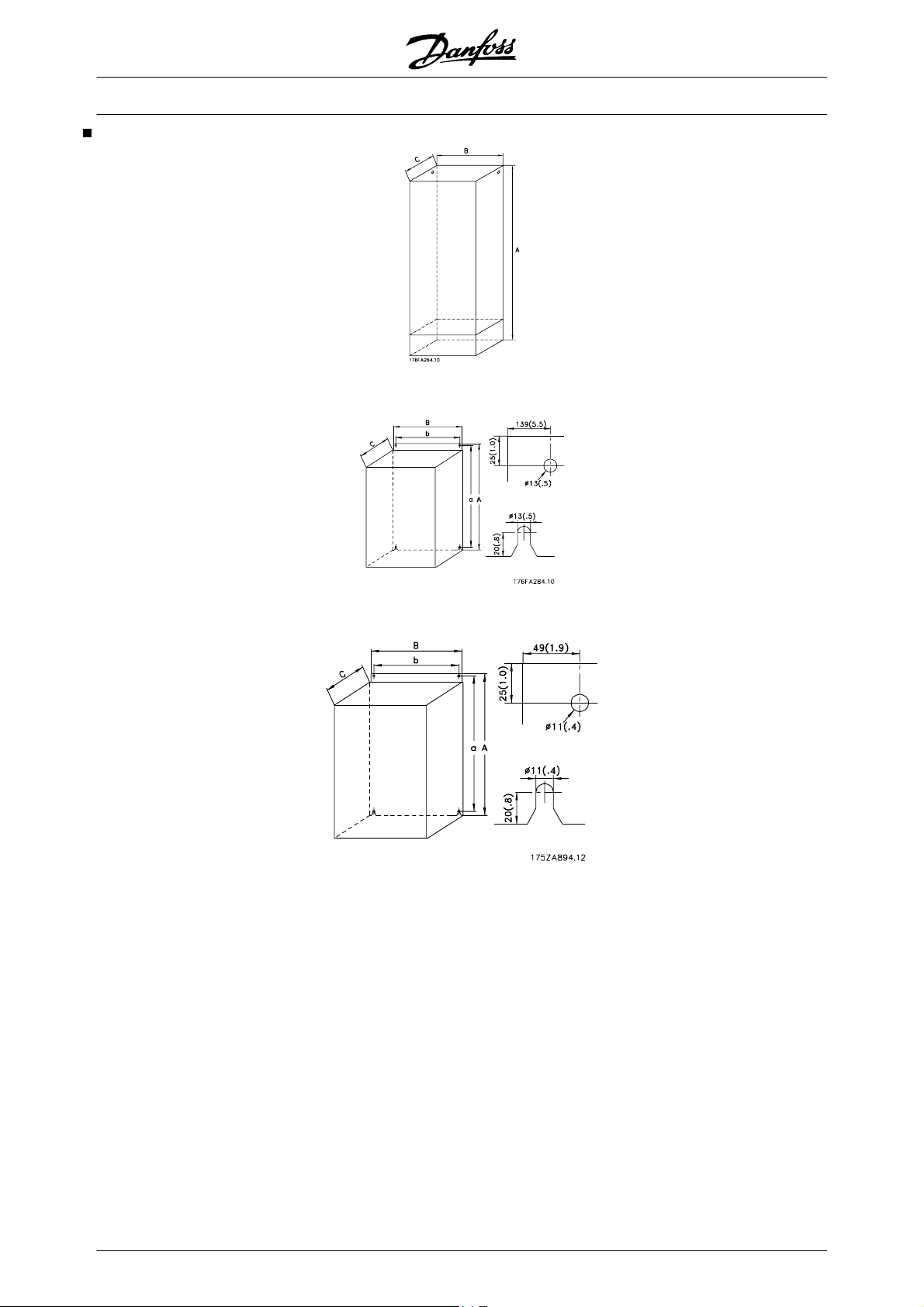
Mechanical dimensions (cont.)
®
VLT
Type H, IP 20, IP 54
5000 Design Guide
Type I, IP 00
Type J, IP 00, IP 21, IP 54
58 MG.52.B2.02 - VLT
®
is a registered Danfoss trademark
Page 60

Mechanical installation
Please pay attention to the requirements
that apply to integration and field mounting kit, see the below list. The information
given in the list must be observed to avoid
serious damage or injury, especially when
installing large units.
The frequency converter must be installed vertically.
The frequency converter is cooled by means of air circulation. For the unit to be able to release its cooling
air, the minimum distance over and below the unit
must be as shown in the illustration below.
To protect the unit from overheating, it must be ensured that the ambient temperature does not rise above
the max. temperature stated for the frequency converter and that the 24-hour average temperature is not
exceeded . The max. temperature and 24-hour aver-
age can be seen from the General Technical Data.
If the ambient temperature is in the range of 45°C -55°
C, derating of the frequency converter will become relevant, see Derating for ambient temperature.
The service life of the frequency converter will be reduced if derating for ambient temperature is not taken
into account.
VLT
®
5000 Design Guide
Mechanical installation
MG.52.B2.02 - VLT
®
is a registered Danfoss trademark 59
Page 61

VLT
®
5000 Design Guide
Installation of VLT 5001-5602
All frequency converters must be installed in a way that
ensures proper cooling.
Cooling
All Bookstyle and Compact units require a minimum
space above and below the enclosure.
Side by side/flange by flange
All frequency converters can be mounted side by side/
flange by flange.
d [mm] Comments
Bookstyle
VLT 5001-5006, 200-240 V 100
VLT 5001-5011, 380-500 V 100
Compact (all enclosure types)
VLT 5001-5006, 200-240 V 100
VLT 5001-5011, 525-600 V 100
VLT 5008-5027, 200-240 V 200
VLT 5016-5062, 380-500 V 200
VLT 5072-5102, 380-500 V 225
VLT 5016-5062, 525-600 V 200
VLT 5032-5052, 200-240 V 225
VLT 5122-5302, 380-500 V 225
VLT 5042-5352, 525-690 V 225
VLT 5352-5552, 380-500 V 225 IP 00 above and below enclosure
VLT 5402-5602, 525-690 V 225
Installation on a plane, vertical surface (no spacers)
Installation on a plane, vertical surface (no spacers)VLT 5001-5011, 380-500 V 100
Installation on a plane, vertical surface (no spacers)
Installation on a plane, vertical surface (no spacers)
IP 54 filter mats must be changed when they are dirty.
IP 21/IP 54 only above enclosure
60 MG.52.B2.02 - VLT
®
is a registered Danfoss trademark
Page 62

VLT
®
5000 Design Guide
Installation of VLT 5352-5552 380-500 V and VLT
5402-5602 525-690 V Compact Nema 1 (IP 21) and
IP 54
Cooling
All units in the above-mentioned series require a minimum space of 225 mm above the enclosure and must
be installed on a flat level surface. This applies to both
Nema 1 (IP 21) and IP 54 units.
Gaining access requires a minimum space of 579 mm
in front of the frequency converter.
Side-by-side
Mechanical installation
Compact Nema 1 (IP 21) and IP 54
All Nema 1 (IP 21) and IP 54 units in the above-mentioned series can be installed side by side without any
space between them, since these units do not require
cooling on the sides.
Filter mats in IP 54 units have to be changed regularly
depending on the operating environment.
NB!
IP54 units are not intended for direct outdoor installation. The IP54 rating does not
relate to other exposures as sun, icing,
wind blown driving rain. Under such circumstances Danfoss recommends to install the units in an enclosure designed for
these environmental conditions. Alternatively, an installation at minimum 0.5 m
above surface and covered by a shed is
recommended.
MG.52.B2.02 - VLT
®
is a registered Danfoss trademark 61
Page 63

Electrical installation
The voltage on the frequency converter is
dangerous when the unit is connected to
mains. Incorrect installation of the motor
or the frequency converter may lead to
material damage or serious injury or it may
be fatal. Consequently, the instructions in
this manual as well as national and local
rules and safety regulations must be complied with.
Touching the electrical parts may be fatal,
even after the mains supply has been disconnected.
Using VLT 5001-5006, 200-240
V and 380-500 V: wait at least 4
minutes.
Using VLT 5008-5052, 200-240
V: wait at least 15 minutes.
Using VLT 5008-5062, 380-500
V: wait at least 15 minutes.
®
VLT
5000 Design Guide
NB!
The RFI switch must be closed (position
ON) when high voltage tests are carried
out (see section RFI Switch).
The mains and motor connection must be
interrupted in the case of high voltage
tests of the total installation if the leakage
currents are too high.
Safety earthing
NB!
The frequency converter has a high leakage current and must be earthed appropriately for safety reasons. Use earth
terminal (see section Electrical installation,
power cables), which enables reinforced
earthing.
Apply national safety regulations.
Using VLT 5072-5302, 380-500
V: wait at least 20 minutes.
Using VLT 5352-5552, 380-500
V: wait at least 40 minutes.
Using VLT 5001-5005, 525-600
V: wait at least 4 minutes.
Using VLT 5006-5022, 525-600
V: wait at least 15 minutes.
Using VLT 5027-5062, 525-600
V: wait at least 30 minutes.
Using VLT 5042-5352, 525-690
V: wait at least 20 minutes.
Using VLT 5402-5602, 525-690
V: wait at least 30 minutes.
NB!
It is the user's or certified electrician's responsibility to ensure correct earthing and
protection in accordance with applicable
national and local norms and standards.
Extra protection (RCD)
ELCB relays, multiple protective earthing or earthing
can be used as extra protection, provided that local
safety regulations are complied with.
In the case of an earth fault, a DC content may develop
in the faulty current.
If ELCB relays are used, local regulations must be observed. Relays must be suitable for protection of 3phase equipment with a bridge rectifier and for a brief
discharge on power-up.
See also the section Special Conditions in the Design
Guide.
Electrical installation - mains supply
Connect the three mains phases to terminals L
.
L
3
, L2,
1
High voltage test
Electrical installation - motor cables
A high voltage test can be carried out by short- circuiting terminals U, V, W, L
max. 2.15 kV DC for one second between this shortcircuit and the chassis.
, L2 and L3 and energizing by
1
NB!
If an unscreened cable is used, some
EMC requirements are not complied with,
see the Design Guide.
62 MG.52.B2.02 - VLT
®
is a registered Danfoss trademark
Page 64
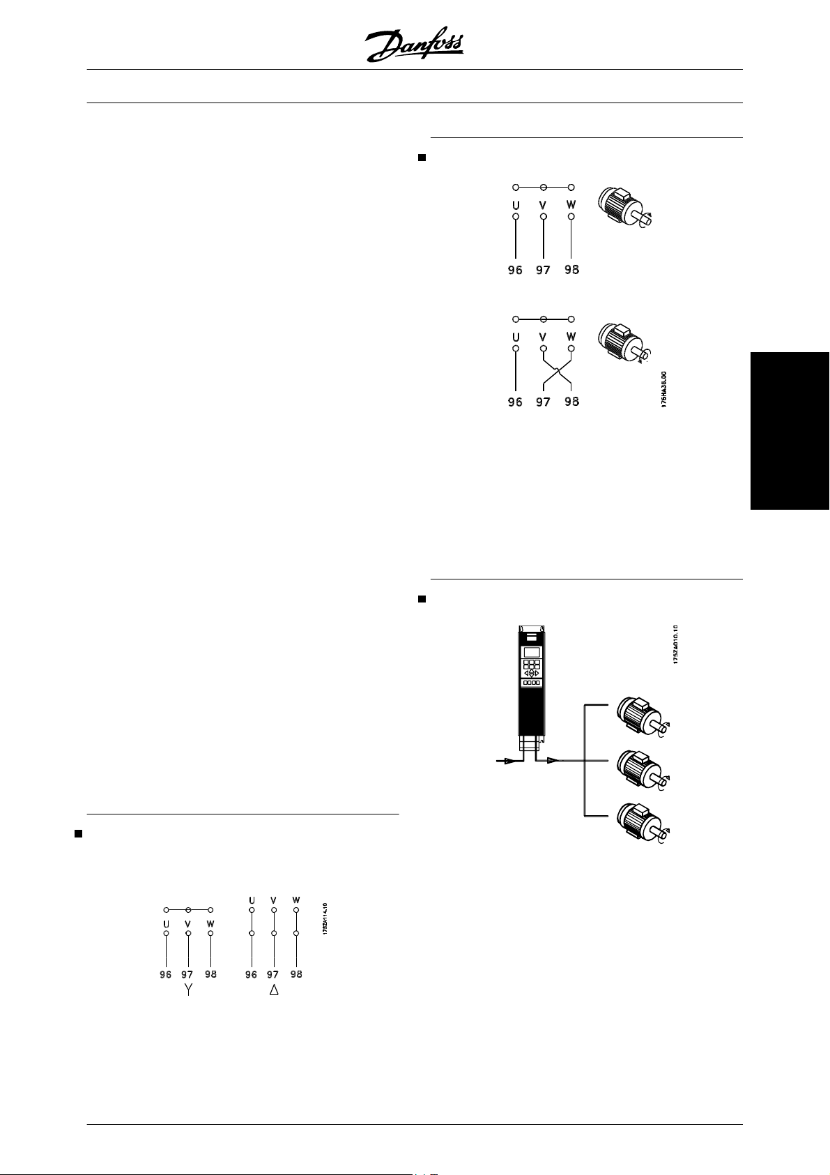
If the EMC specifications regarding emission are to be complied with, the motor
cable must be screened, unless otherwise
stated for the RFI filter in question. It is
important to keep the motor cable as short
as possible so as to reduce the noise level
and leakage currents to a minimum.
The motor cable screen must be connected to the metal cabinet of the frequency
converter and to the metal cabinet of the
motor. The screen connections are to be
made with the biggest possible surface
(cable clamp). This is enabled by different
installation devices in the different frequency converters.
®
VLT
5000 Design Guide
Direction of motor rotation
Installation with twisted screen ends (pigtails) is to be
avoided, since these spoil the screening effect at higher frequencies.
If it is necessary to break the screen to install a motor
isolator or motor contactor, the screen must be continued at the lowest possible HF impedance.
The frequency converter has been tested with a given
length of cable and a given cross-section of that cable.
If the cross-section is increased, the cable capacitance
- and thus the leakage current - increases, and the cable length must be reduced correspondingly.
When frequency converters are used together with
sine-wave filters to reduce the acoustic noise from a
motor, the switching frequency must be set according
to the sine-wave filter instruction in Parameter 411.
When setting the switching frequency higher than 3
kHz, the output current is derated in SFAVM mode. By
changing Parameter 446 to 60° AVM mode, the frequency at which the current is derated is moved upwards. Please see Design Guide.
The factory setting is for clockwise rotation with the
frequency transformer output connected as follows.
Terminal 96 connected to U-phase
Terminal 97 connected to V-phase
Terminal 98 connected to W-phase
The direction of motor rotation can be changed by
switching two phases in the motor cable.
Parallel coupling of motors
Electrical installation
Connection of motor
All types of 3-phased asynchronous standard motors
can be used with the VLT 5000 Series.
Normally, small motors are star-connected (200/400
V, Δ/Y).
Large motors are delta-connected (400/690 V, Δ/Y).
MG.52.B2.02 - VLT
®
is a registered Danfoss trademark 63
Frequency converters are able to control several motors connected in parallel. If the motors are to have
different rpm values, the motors must have different
rated rpm values. Motor rpm is changed simultaneously, which means that the ratio between the rated
rpm values is maintained across the range.
The total current consumption of the motors is not to
exceed the maximum rated output current I
VLT,N
for the
frequency converter.
Problems may arise at the start and at low rpm values
if the motor sizes are widely different. This is because
the relatively high ohmic resistance in small motors
Page 65
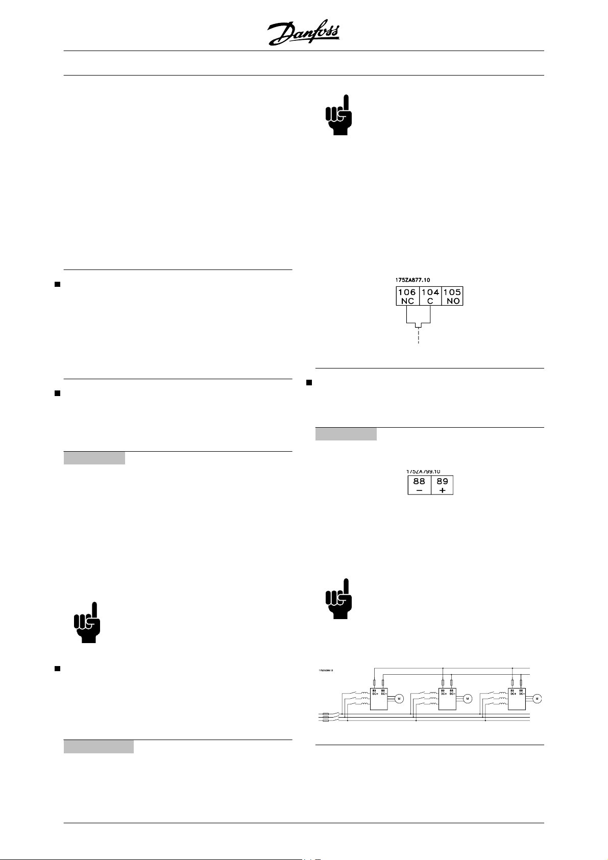
calls for a higher voltage at the start and at low rpm
values.
In systems with motors connected in parallel, the electronic thermal relay (ETR) of the frequency converter
cannot be used as motor protection for the individual
motor. Consequently, additional motor protection is
required, such as thermistors in each motor (or individual thermal relays) suitable for frequency converter
use.
Please note that the individual motor cable for each
motor must be summed and is not to exceed the total
motor cable length permitted.
Motor thermal protection
The electronic thermal relay in UL-approved frequency
converters has received the UL-approval for single
motor protection when parameter 128 has been set for
ETR Trip and parameter 105 has been programmed to
the rated motor current (see motor nameplate).
VLT
®
5000 Design Guide
NB!
This function is only available on VLT
5032-5052, 200-240 V; VLT 5122-5552,
380-500 V; and VLT 5042-5602, 525-690
V.
If the temperature of the brake resistor
gets too high and the thermal switch drops
out, the frequency converter will stop
braking. The motor will start coasting.
A KLIXON switch must be installed that is
'normally closed'. If this function is not
used, 106 and 104 must be short-circuited
together.
Electrical installation - brake cable
(Only standard with brake and extended with brake.
Typecode: SB, EB, DE, PB).
No.
Function
81, 82 Brake resistor terminals
The connection cable to the brake resistor must be
screened. Connect the screen by means of cable
clamps to the conductive back plate at the frequency
converter and to the metal cabinet of the brake resistor.
Size the brake cable cross-section to match the brake
torque. See also Brake instructions, MI.90.FX.YY and
MI.50.SX.YY for further information regarding safe installation.
NB!
Please note that voltages up to 1099 V
DC, depending on the supply voltage,
may occur on the terminals.
Electrical installation - brake resistor temperature
switch
Torque: 0.5-0.6 Nm
Screw size: M3
Electrical installation - loadsharing
(Only extended with typecode EB, EX, DE, DX).
No.
Function
88, 89 Loadsharing
Terminals for loadsharing
The connection cable must be screened and the max.
length from the frequency converter to the DC bar is
25 metres.
Load sharing enables linking of the DC intermediate
circuits of several frequency converters.
NB!
Please note that voltages up to 1099 V DC
may occur on the terminals.
Load sharing calls for extra equipment.
For further information please consult
Loadsharing Instructions MI.50.NX.XX.
No.
Function
106, 104, 105 Brake resistor temperature switch.
64 MG.52.B2.02 - VLT
®
is a registered Danfoss trademark
Page 66
VLT
®
5000 Design Guide
Tightening-up torques and screw sizes
The table shows the torque required when fitting terminals to the frequency converter. For VLT 5001-5027
200-240 V, VLT 5001-5102 380-500 V and VLT
5001-5062 525-600 V, the cables must be fastened
with screws. For VLT 5032 - 5052 200-240 V, VLT
5122-5552 380-500 V, VLT 5042-5602 525-690 V the
cables must be fastened with bolts.
These figures apply to the following terminals:
Mains terminals Nos 91, 92, 93
L1, L2, L3
Motor terminals
Nos 96, 97, 98
U, V, W
Earth terminal
No 94, 95, 99
Brake resistor terminals
81, 82
Loadsharing
88, 89
VLT type
200-240 V
Torque [Nm] Screw/
Tool
Boltsize
5001-5006 0,6 M3 Slotted screw
5008 IP20 1,8 M4 Slotted screw
5008-5011 IP54 1,8 M4 Slotted screw
5011-5022 IP20 3 M5 4 mm Allen wrench
5016-5022
31)
IP54 3 M5 4 mm Allen wrench
5027 6 M6 4 mm Allen wrench
5032-5052
380-500 V
11,3 M8 (bolt and stud)
5001-5011 0,6 M3 Slotted screw
5016-5022 IP20 1,8 M4 Slotted screw
5016-5027 IP54 1,8 M4 Slotted screw
5027-5042 IP20 3 M5 4 mm Allen wrench
5032-5042
3)
IP54 3 M5 4 mm Allen wrench
5052-5062 6 M6 5 mm Allen wrench
5072-5102 IP20 15 M6 6 mm Allen wrench
5122-5302
5352-5552
2)
4)
5)
IP54
19 M10 bolt 16 mm wrench
19 M10 bolt (compression
24 M8 8 mm Allen wrench
16 mm wrench
lug)
525-600 V
5001-5011 0,6 M3 Slotted screw
5016-5027 1,8 M4 Slotted screw
5032-5042 3 M5 4 mm Allen wrench
5052-5062
525-690 V
5042-5352
5402-5602
4)
5)
6 M6 5 mm Allen wrench
19 M10 bolt 16 mm wrench
19 M10 bolt (compression
16 mm wrench
lug)
Electrical installation
1) Brake terminals: 3,0 Nm, Nut: M6
2) Brake and loadsharing: 14 Nm, M6 Allen screw
3) IP54 with RFI - Line terminals 6Nm, Screw: M6 - 5 mm Allen wrench
4) Loadsharing and brake terminals: 9,5 Nm; Bolt M8
5) Brake terminals: 9,5 Nm; Bolt M8.
MG.52.B2.02 - VLT
®
is a registered Danfoss trademark 65
Page 67
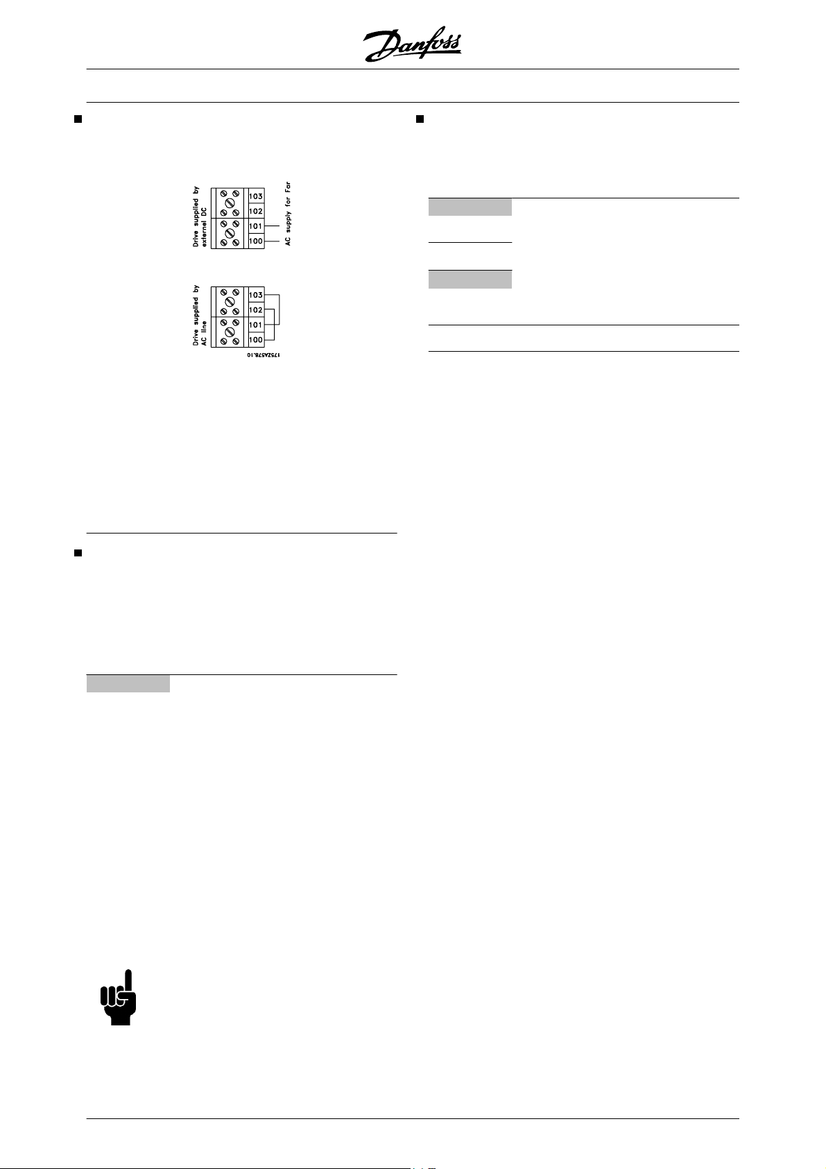
VLT
®
5000 Design Guide
Electrical installation - external fan supply
Torque 0,5-0,6 Nm
Screwsize: M3
Available in 5122-5552, 380-500 V; 5042-5602,
525-690 V, 5032-5052, 200-240 V in all enclosure
types.
Only for IP54 units in the power range VLT 5016-5102,
380-500 V and VLT 5008-5027, 200-240 V AC. If the
drive is supplied by the DC bus (loadsharing), the internal fans are not supplied with AC power. In this case
they must be supplied with an external AC supply.
Electrical installation - relay outputs
Torque: 0.5 - 0.6 Nm
Screw size: M3
No.
Function
1-3 Relay output, 1+3 break, 1+2 make
See parameter 323 of the Operating
Instructions. See also General techni-
cal data.
4, 5
Relay output, 4+5 make See parameter 326 of the Operating Instructions.
See also General technical data.
Electrical installation - 24 Volt external DC supply
(Only extended versions. Typecode: PS, PB, PD, PF,
DE, DX, EB, EX).
Torque: 0.5 - 0.6 Nm
Screw size: M3
No.
Function
35, 36 24 V external DC supply
External 24 V DC supply can be used as low-voltage
supply to the control card and any option cards installed. This enables full operation of the LCP (incl. parameter setting) without connection to mains. Please
note that a warning of low voltage will be given when
24 V DC has been connected; however, there will be
no tripping. If 24 V external DC supply is connected or
switched on at the same time as the mains supply, a
time of min. 200 msec. must be set in parameter 120
Start delay.
A pre-fuse of min. 6 Amp, slow-blow, can be fitted to
protect the external 24 V DC supply. The power consumption is 15-50 W, depending on the load on the
control card.
NB!
Use 24 V DC supply of type PELV to ensure correct galvanic isolation (type
PELV) on the control terminals of the frequency converter.
66 MG.52.B2.02 - VLT
®
is a registered Danfoss trademark
Page 68
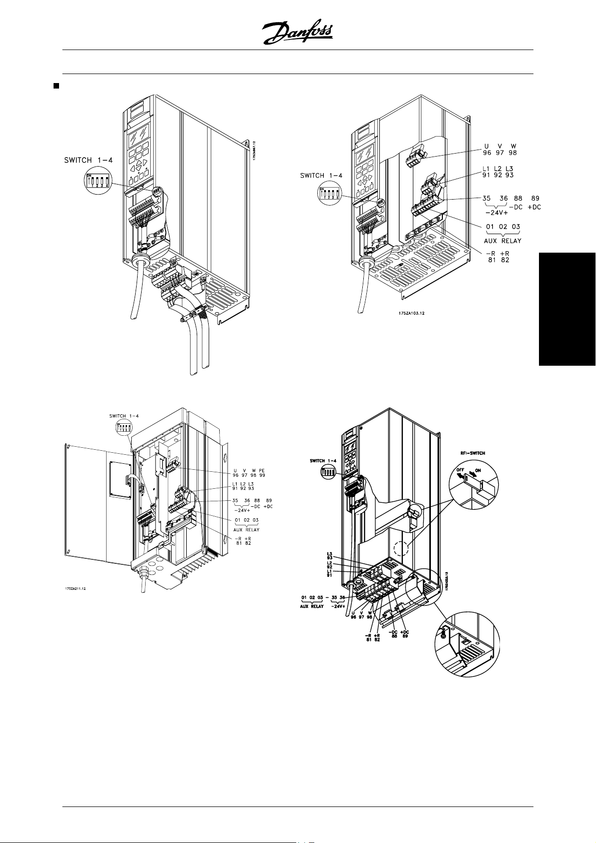
Electrical installation, power cables
VLT
®
5000 Design Guide
Bookstyle
VLT 5001-5006 200-240 V
VLT 5001-5011 380-500 V
Electrical installation
Compact IP 20/Nema 1
Compact IP 54
VLT 5001-5006 200-240 V
VLT 5001-5011 380-500 V
VLT 5001-5011 525-600 V
MG.52.B2.02 - VLT
®
Compact IP 20/Nema 1
VLT 5008-5027 200-240 V
VLT 5016-5062 380-500 V
VLT 5016-5062 525-600 V
is a registered Danfoss trademark 67
Page 69
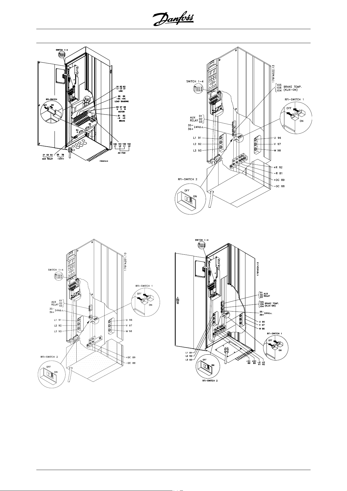
VLT
®
5000 Design Guide
Compact IP 54
VLT 5008-5027 200-240 V
VLT 5016-5062 380-500 V
Compact IP 00/NEMA 1 (IP 20)
VLT 5032-5052 200-240 V
Compact IP 54
VLT 5032-5052 200-240 V
68 MG.52.B2.02 - VLT
®
is a registered Danfoss trademark
Page 70
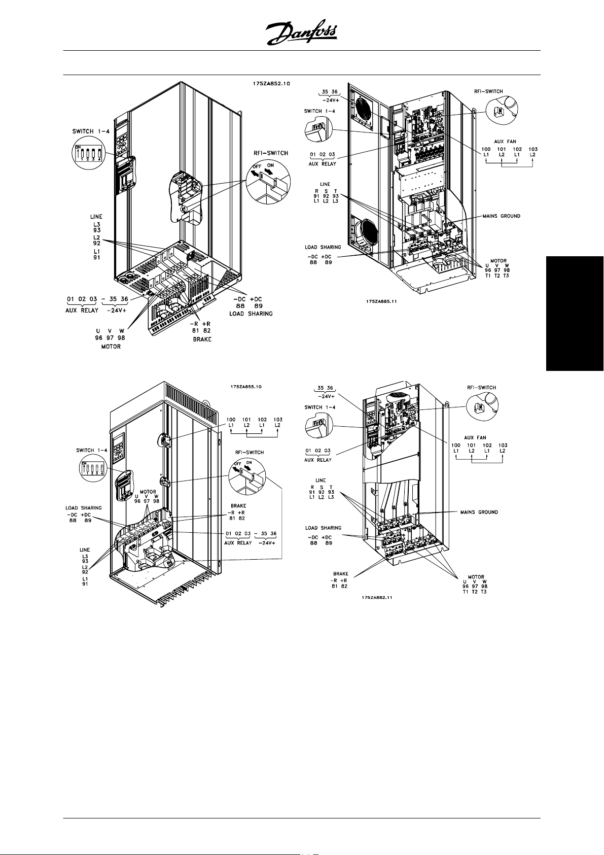
VLT
®
5000 Design Guide
Compact IP 20
VLT 5072-5102 380-500 V
Compact IP 54
VLT 5072-5102 380-500 V
Compact IP 21/IP 54 with disconnect and fuse
VLT 5122-5152 380-500 V, VLT 5042-5152 525-690 V
NOTE: The RFI switch has no function in the 525-690 V drives
Compact IP 00 without disconnect and fuse
VLT 5122-5152 380-500 V, VLT 5042-5152 525-690 V
Electrical installation
MG.52.B2.02 - VLT
®
is a registered Danfoss trademark 69
Page 71
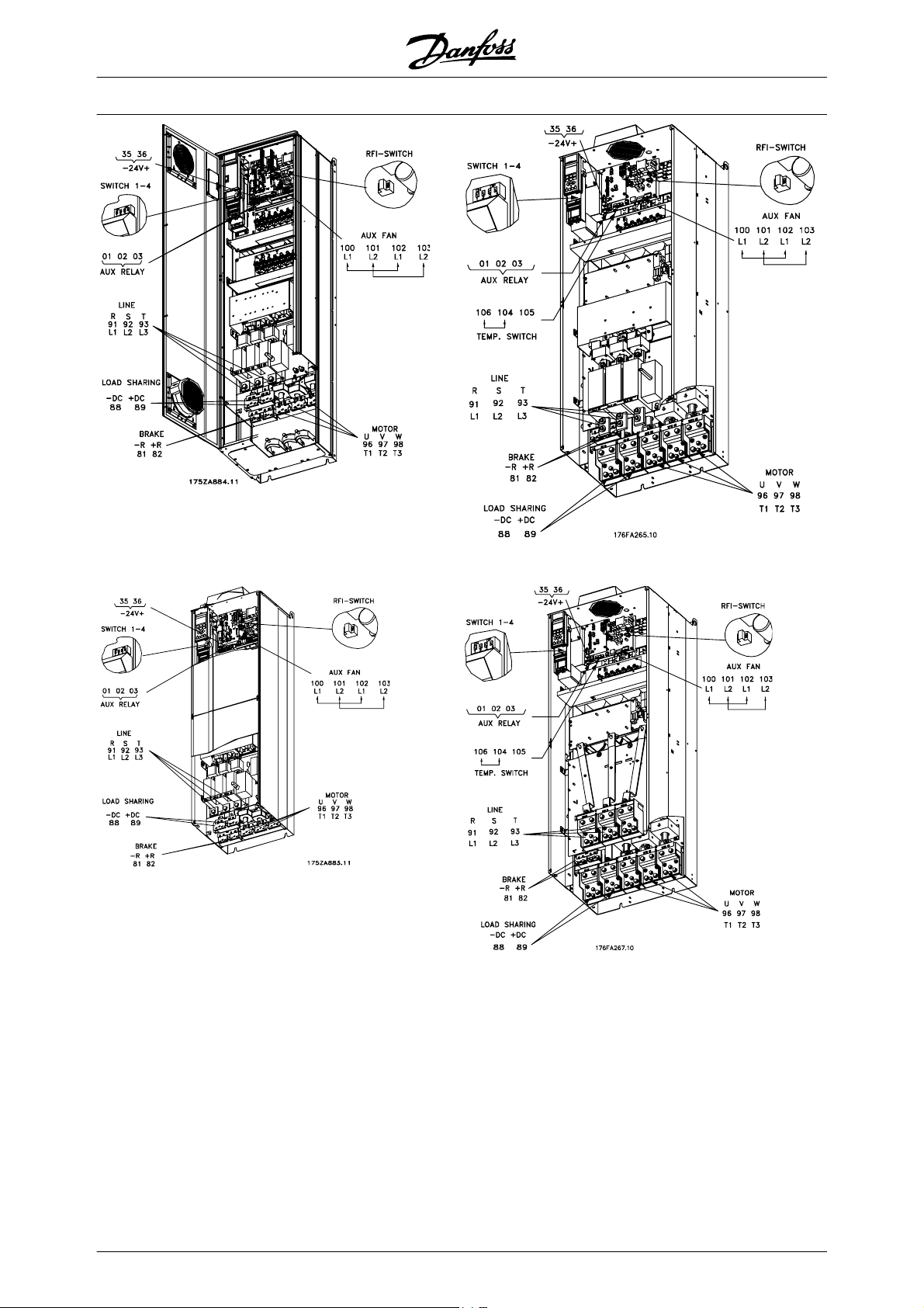
VLT
®
5000 Design Guide
Compact IP 21/IP 54 with disconnect and fuse
VLT 5202-5302 380-500 V, VLT 5202-5352 525-690 V
Note: The RFI switch has no function in the 525-690 V drives
Compact IP 00 with disconnect and fuse
VLT 5202-5302 380-500 V, VLT 5202-5352 525-690 V
Compact IP 00 with disconnect and fuse
VLT 5352-5552 380-500 V, VLT 5402-5602 525-690 V
Compact IP 00 without disconnect and fuse
VLT 5352-5552 380-500 V, VLT 5402-5602 525-690 V
Note: The RFI switch has no function in the 525-690 V drives
70 MG.52.B2.02 - VLT
®
is a registered Danfoss trademark
Page 72
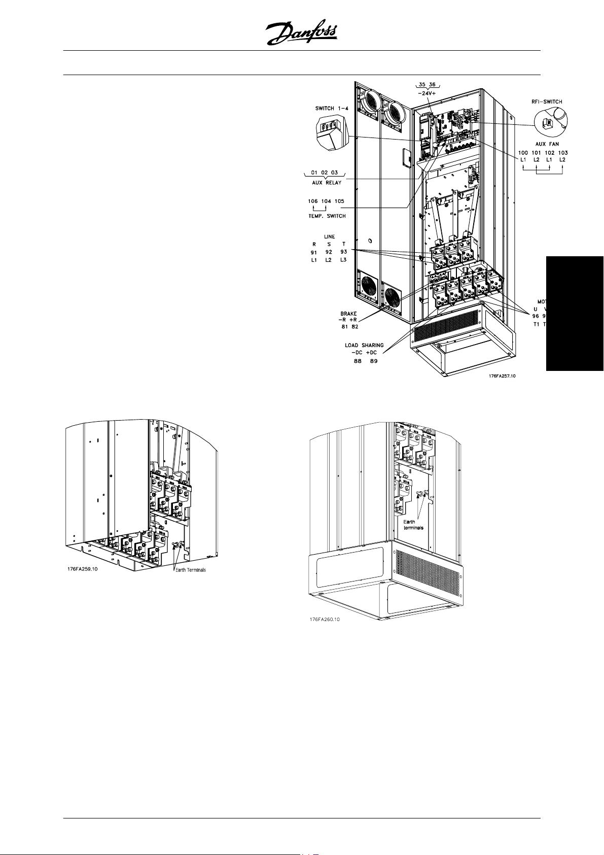
®
VLT
5000 Design Guide
Position of earth terminals, IP 00 Position of earth terminals, IP 21/ IP 54
Compact IP 21/IP 54 without disconnect and fuse
VLT 5352-5552 380-500 V, VLT 5402-5602, 525-690 V
Note: The RFI switch has no function in the 525-690 V drives.
Electrical installation
MG.52.B2.02 - VLT
®
is a registered Danfoss trademark 71
Page 73
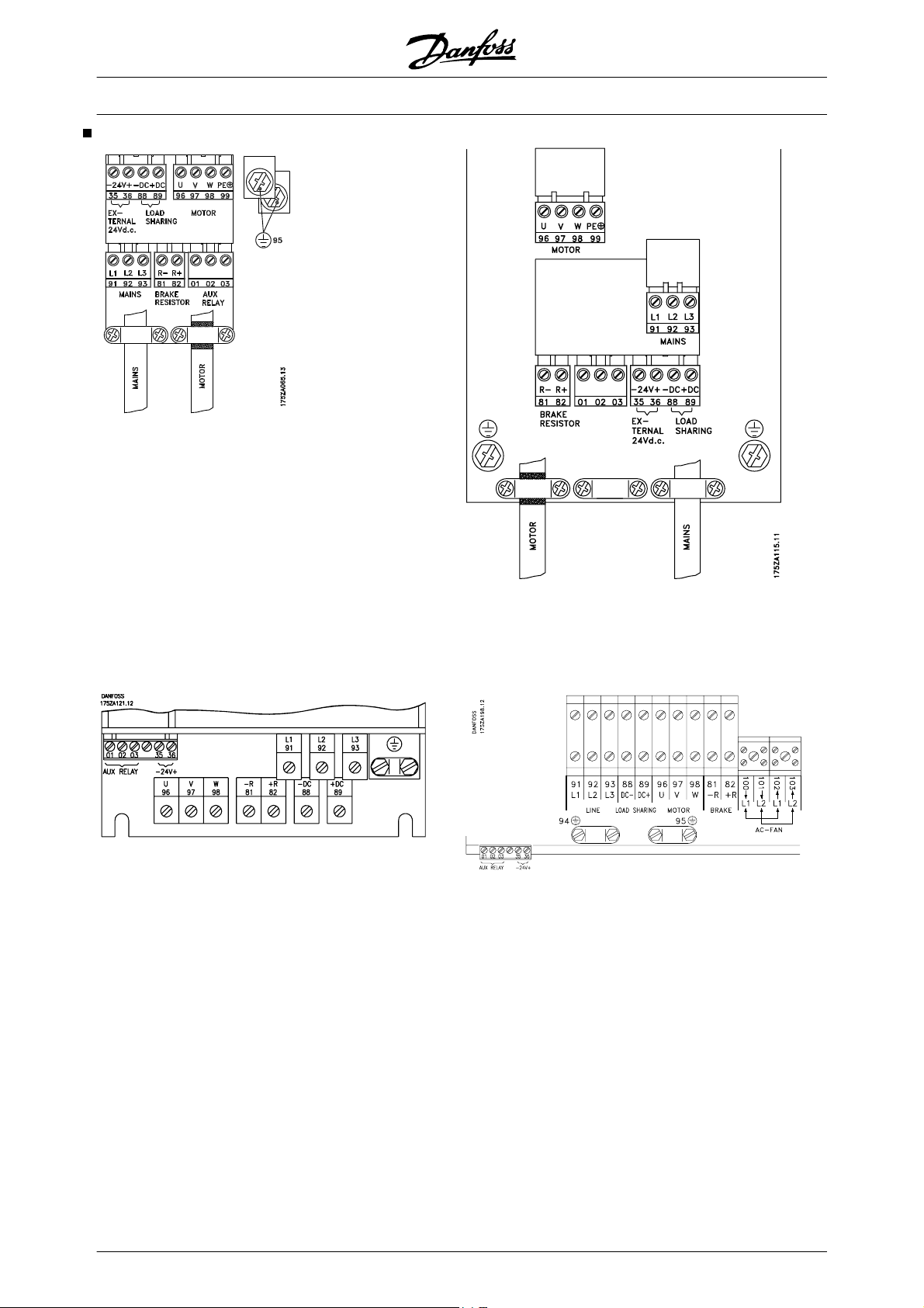
Electrical installation, power cables
VLT
®
5000 Design Guide
Bookstyle
VLT 5001-5006 200-240 V
VLT 5001-5011 380-500 V
Compact IP 00/NEMA 1
VLT 5008-5027 200-240 V
VLT 5016-5102 380-500 V
VLT 5016-5062 525-600 V
Compact IP 54
VLT 5001-5006 200-240 V
VLT 5001-5011 380-500 V
VLT 5001-5011 525-600 V
Compact IP 54
VLT 5008-5027 200-240 V
VLT 5016-5062 380-500 V
72 MG.52.B2.02 - VLT
®
is a registered Danfoss trademark
Page 74

VLT
®
5000 Design Guide
Compact IP 00/NEMA 1 (IP20)
VLT 5032-5052 200-240 V
Compact IP 54
VLT 5072-5102 380-500 V
Compact IP 54
VLT 5032-5052 200-240 V
Electrical installation
MG.52.B2.02 - VLT
®
is a registered Danfoss trademark 73
Page 75
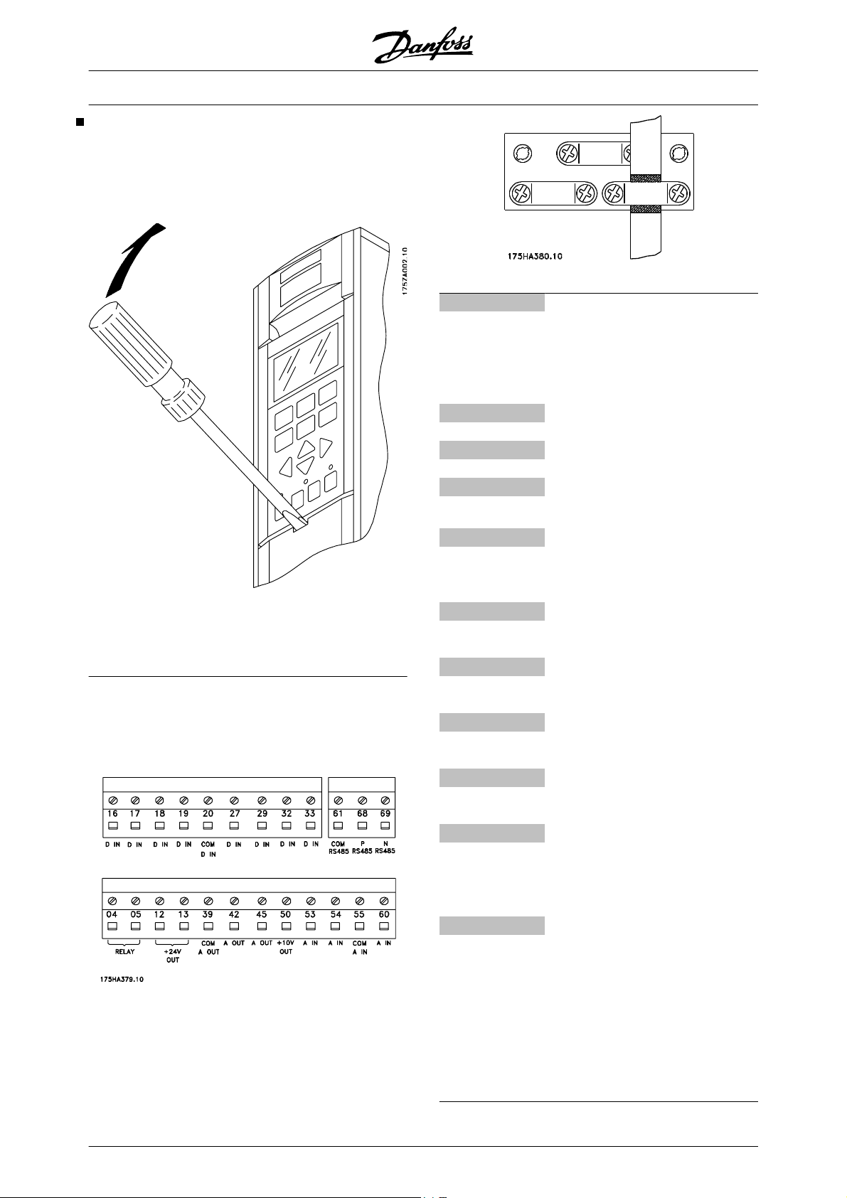
Electrical installation - control cables
All terminals for the control cables are located under
the protective cover of the frequency converter. The
protective cover (see drawing) can be removed by
means of a pointed object - a screwdriver or similar.
®
VLT
5000 Design Guide
No. Function
12, 13 Voltage supply to digital inputs For
the 24 V DC to be usable for the
digital inputs, switch 4 on the control card must be closed. position
"ON".
16-33 Digital inputs/encoder inputs
20 Ground for digital inputs
39 Ground for analogue/digital outputs
Once the protective cover has been removed, the actual EMC-correct installation can start. See drawings
in the section, EMC correct installation.
Tightening-up torque: 0.5-0.6 Nm
Screw size: M3
See section earthing of braided screened/armoured
control cables.
42, 45 Analogue/digital outputs for indicat-
ing frequency, reference, current
and torque
50 Supply voltage to potentiometer
and thermistor 10 V DC
53, 54 Analogue reference input, voltage
0 - ±10 V
55 Ground for analogue reference in-
puts
60 Analogue reference input, current
0/4-20 mA
61 Termination for serial communica-
tion. See section Bus connection.
This terminal is normally not to be
used.
68, 69 RS 485 interface, serial communi-
cation. Where the frequency converter is connected to a bus,
switches 2 and 3 (switches 1- 4)
must be closed on the first and the
last frequency converter. On the remaining frequency converters,
switches 2 and 3 must be open.
The factory setting is closed (position “ON”).
74 MG.52.B2.02 - VLT
®
is a registered Danfoss trademark
Page 76

Electrical installation - Signal Input/Output
VLT
®
5000 Design Guide
Conversion of analogue inputs
Current input signal to voltage input
0-20 mA ⇒ 0-10 V
4-20 mA ⇒ 2-10 V
Connect 510 ohms resistor between input terminal 53
and 55 and adjust minimum and maximum values in parameters 309, and 310 or 54 and 55 and adjust minimum
and maximum values in parameters 312 and 313.
Electrical installation
MG.52.B2.02 - VLT
®
is a registered Danfoss trademark 75
Page 77

Electrical installation - bus connection
The serial bus connection in accordance with the RS
485 (2-conductor) norm is connected to terminals
68/69 of the frequency converter (signals P and N).
Signal P is the positive potential (TX+,RX+), while signal N is the negative potential (TX-,RX-).
If more than one frequency converter is to be connected to a given master, use parallel connections.
In order to avoid potential equalizing currents in the
screen, the cable screen can be earthed via terminal
61, which is connected to the frame via an RC-link.
VLT
®
5000 Design Guide
Bus termination
The bus must be terminated by a resistor network at
both ends. For this purpose, set switches 2 and 3 on
the control card for "ON".
DIP Switches 1-4
The dipswitch is located on the control card.
It is used for serial communication, terminals 68 and
69.
The switching position shown is the factory setting.
Switch 1 has no function.
Switches 2 and 3 are used for terminating an RS 485
interface, serial communication.
Switch 4 is used for separating the common potential
for the internal 24 V DC supply from the common potential of the external 24 V DC supply.
NB!
Please note that when Switch 4 is in position "OFF", the external 24 V DC supply
is galvanically isolated from the frequency
converter.
76 MG.52.B2.02 - VLT
®
is a registered Danfoss trademark
Page 78

VLT
®
5000 Design Guide
Electrical installation - EMC precautions
The following is a guideline to good engineering practice, when installing drives. Following these guidelines
is advised, where compliance with EN 61000-6-3, EN
61000-6-4, EN 55011 or EN 61800-3 First environ-
ment is required. If the installation is in EN 61800-3
Second environment, i.e. industrial networks or in an
installation that has its own transformer, it is acceptable to deviate from these guidelines. It is however not
recommended. See also CE labelling, Emission and
EMC test results under special conditions in the Design
Guide for further details.
Good engineering practice to ensure EMC-correct
electrical installation:
• Use only braided screened/armoured motor
cables and braided screened/armoured control cables. The screen should provide a minimum coverage of 80%. The screen material
must be metal, not limited to but typically copper, aluminium, steel or lead. There are no
special requirements for the mains cable.
• Installations using rigid metal conduits are
not required to use screened cable, but the
motor cable must be installed in conduit separate from the control and mains cables. Full
connection of the conduit from the drive to the
motor is required. The EMC performance of
flexible conduits varies a lot and information
from the manufacturer must be obtained.
• Connect the screen/armour/conduit to earth
at both ends for motor cables as well as for
control cables. In some cases, it is not possible to connect the screen in both ends. In
these cases, it is important to connect the
screen at the frequency converter. See also
Earthing of braided screened/armoured control cables.
• Avoid terminating the screen/armour with
twisted ends (pigtails). Such a termination increases the high frequency impedance of the
screen, which reduces its effectiveness at
high frequencies. Use low impedance cable
clamps or EMC cable glands instead.
• It is important to ensure good electrical contact between the mounting plate on which the
frequency converter is installed and the metal
chassis of the frequency converter. However,
this does not apply to IP 54 units as they are
designed for wall-mounting and VLT
5122-5552 380-500 V, 5042-5602 525-690 V
and VLT 5032-5052 200-240 V in IP20/
NEMA 1 enclosure and IP 54/NEMA 12 enclosure.
• Use starwashers and galvanically conductive
installation plates to secure good electrical
connections for IP00 and IP20 installations.
• Avoid using unscreened/unarmoured motor
or control cables inside cabinets housing the
drive(s), whenever this can be avoided.
• An uninterrupted high frequency connection
between the frequency converter and the
motor units is required for IP54 units.
The illustration shows an example of an EMC-correct
electrical installation of an IP 20 frequency converter;
the frequency converter has been fitted in an installation cabinet with an output contactor and connected to
a PLC, which in this example is installed in a separate
cabinet. In IP 54 units and VLT 5032-5052, 200-240 V
in IP20/IP21/NEMA 1 enclosure screened cables are
connected by using EMC conduits to ensure proper
EMC performance. See illustration. Other ways of
making the installation may have as good an EMC
performance, provided the above guide lines to engineering practice are followed.
Please note, that when the installation is not carried
through according to the guideline as well as when
unscreened cables and control wires are used, some
emission requirements are not complied with, although the immunity requirements are fulfilled. See the
section EMC test results in the Design Guide for further
details.
Electrical installation
MG.52.B2.02 - VLT
®
is a registered Danfoss trademark 77
Page 79

VLT
®
5000 Design Guide
Use of emc-correct cables
Braided screened/armoured cables are recommended
to optimise EMC immunity of the control cables and
however, a screen with a lower transfer impedance
(Z
) value is more effective than a screen with a higher
T
transfer impedance (Z
the EMC emission from the motor cables.
The ability of a cable to reduce the in- and outgoing
radiation of electric noise depends on the transfer impedance (Z
). The screen of a cable is normally de-
T
signed to reduce the transfer of electric noise;
78 MG.52.B2.02 - VLT
).
T
®
is a registered Danfoss trademark
Page 80
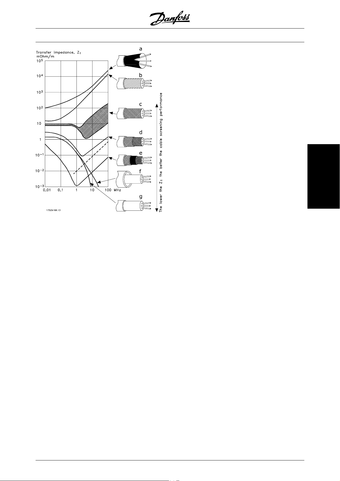
VLT
®
5000 Design Guide
Transfer impedance (Z
) can be assessed on the basis
T
of the following factors:
The conductibility of the screen material.
-
The contact resistance between the individ-
-
ual screen conductors.
The screen coverage, i.e. the physical area
-
of the cable covered by the screen - often
stated as a percentage value.
Screen type, i.e. braided or twisted pattern.
-
Aluminium-clad with copper wire.
Twisted copper wire or armoured steel wire cable.
Single-layer braided copper wire with varying percentage
screen coverage.
This is the typical Danfoss reference cable.
Double-layer braided copper wire.
Twin layer of braided copper wire with a magnetic, screened/
armoured intermediate layer.
Cable that runs in copper tube or steel tube.
Electrical installation
Transfer impedance (ZT) is rarely stated by cable manufacturers, but it is often possible to estimate transfer
impedance (Z
) by assessing the physical design of
T
the cable.
Lead cable with 1.1 mm wall thickness.
MG.52.B2.02 - VLT
®
is a registered Danfoss trademark 79
Page 81
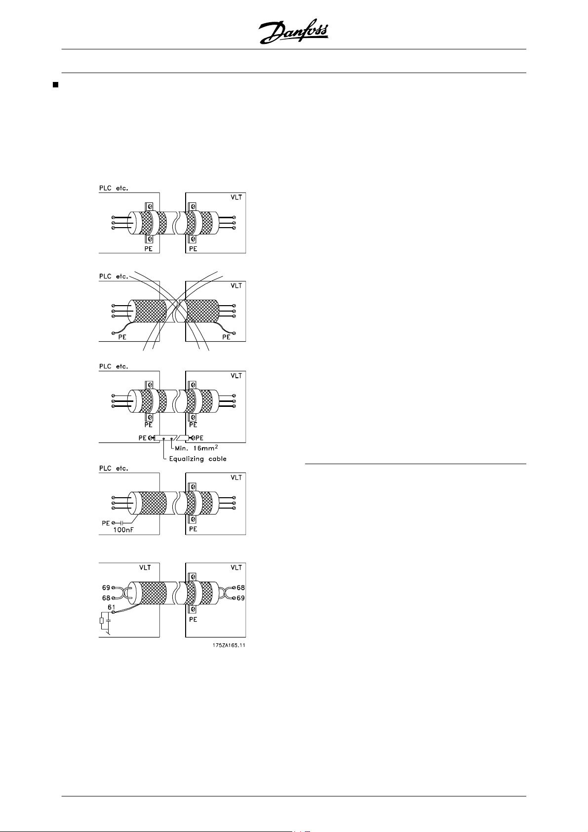
VLT
®
5000 Design Guide
Electrical installation - earthing of control cables
Generally speaking, control cables must be braided
screened/armoured and the screen must be connected by means of a cable clampat both ends to the metal
cabinet of the unit.
The drawing below indicates how correct earthing is
carried out and what to be done if in doubt.
Correct earthing
Control cables and cables for serial communication
must be fitted with cable clamps at both ends to ensure
the best possible electrical contact
Wrong earthing
Do not use twisted cable ends (pigtails), since these
increase the screen impedance at high frequencies.
Protection with respect to earth potential between
PLC and VLT
If the earth potential between the frequency converter
and the PLC (etc.) is different, electric noise may occur
that will disturb the whole system. This problem can be
solved by fitting an equalising cable, to be placed next
to the control cable. Minimum cable cross-section: 16
2
.
mm
For 50/60 Hz earth loops
If very long control cables are used, 50/60 Hz earth
loops may occur. This problem can be solved by connecting one end of the screen to earth via a 100nF
capacitor (keeping leads short).
Cables for serial communication
Low-frequency noise currents between two frequency
converters can be eliminated by connecting one end
of the screen to terminal 61. This terminal is connected
to earth via an internal RC link. It is recommended to
use twisted-pair cables to reduce the differential mode
interference between the conductors.
80 MG.52.B2.02 - VLT
®
is a registered Danfoss trademark
Page 82
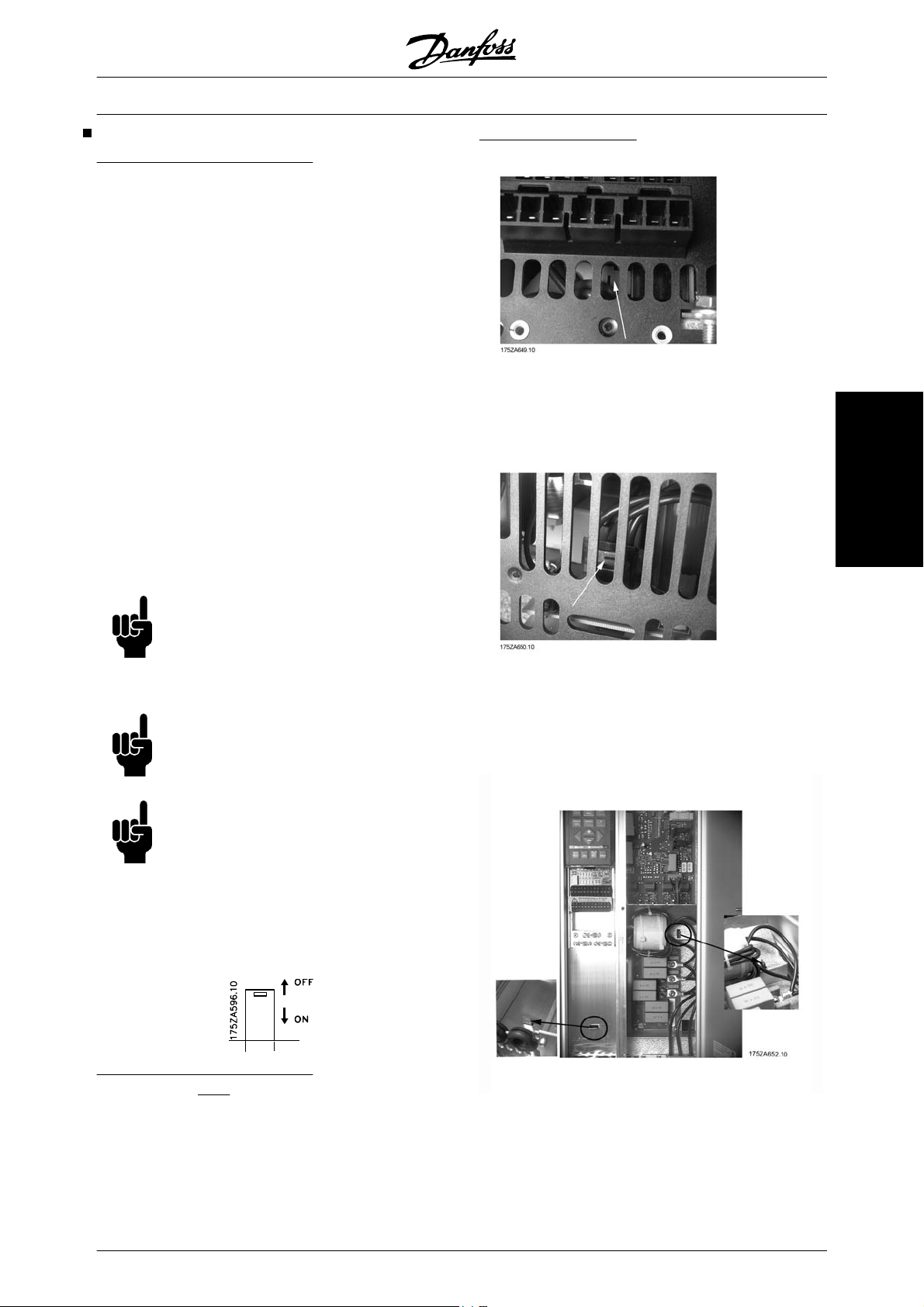
VLT
®
5000 Design Guide
RFI switch
Mains supply isolated from earth:
If the frequency converter is supplied from an isolated
mains source (IT mains) or TT/TN-S mains with grounded leg, the RFI switch is recommended to be turned
off (OFF)
case optimum EMC performance is needed, parallel
motors are connected or the motor cable length is
above 25 m, it is recommended to set the switch in ON
position.
In OFF position, the internal RFI capacities (filter capacitors) between the chassis and the intermediate
circuit are cut off to avoid damage to the intermediate
circuit and to reduce the earth capacity currents (according to IEC 61800-3).
Please also refer to the application note VLT on IT
mains, MN.90.CX.02. It is important to use isolation
monitors that are capable for use together with power
electronics (IEC 61557-8).
1)
Not possible with 5042-5602, 525-690 V units.
1)
. For further reference, see IEC 364-3. In
Position of RFI switches
Bookstyle IP 20
VLT 5001 - 5006 200 - 240 V
VLT 5001 - 5011 380 - 500 V
Electrical installation
NB!
The RFI switch is not to be operated with
mains connected to the unit. Check that
the mains supply has been disconnected
before operating the RFI switch.
NB!
Open RFI switch is only allowed at factory
set switching frequencies.
NB!
The RFI switch connects the capacitors
galvanically to earth.
The red switches are operated by means of e.g. a
screwdriver. They are set in the OFF position when
they are pulled out and in ON position when they are
pushed in. Factory setting is ON.
Compact IP 20/NEMA 1
VLT 5001 - 5006 200 - 240 V
VLT 5001 - 5011 380 - 500 V
VLT 5001 - 5011 525 - 600 V
Mains supply connected to earth:
The RFI switch
frequency converter to comply with the EMC standard.
MG.52.B2.02 - VLT
must be in ON position in order for the
®
is a registered Danfoss trademark 81
Compact IP 20/NEMA 1
VLT 5008 200 - 240 V
VLT 5016 - 5022 380 - 500 V
VLT 5016 - 5022 525 - 600 V
Page 83
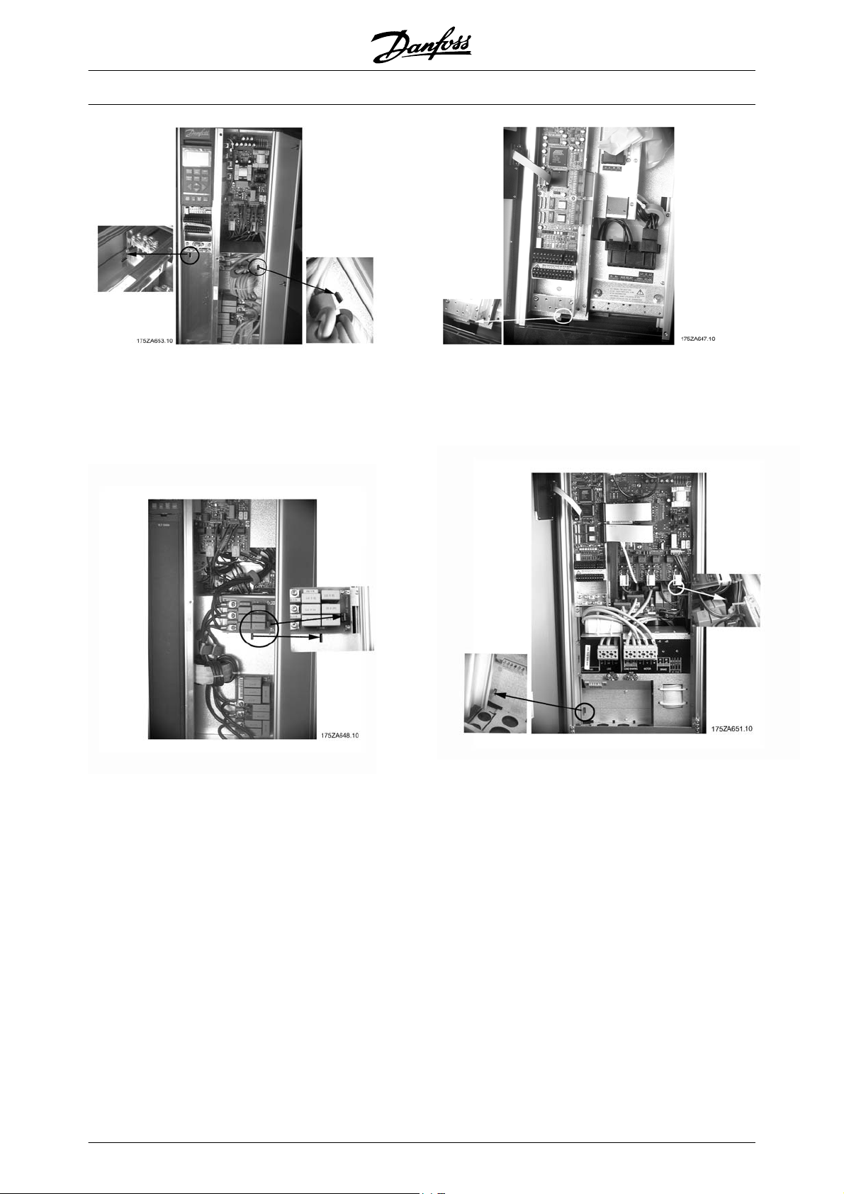
VLT
®
5000 Design Guide
Compact IP 20/NEMA 1
VLT 5011 - 5016 200 - 240 V
VLT 5027 - 5032 380 - 500 V
VLT 5027 - 5032 525 - 600 V
Compact IP 20/NEMA 1
VLT 5022 - 5027 200 - 240 V
VLT 5042 - 5102 380 - 500 V
VLT 5042 - 5062 525 - 600 V
Compact IP 54
VLT 5001 - 5006 200 - 240 V
VLT 5001 - 5011 380 - 500 V
Compact IP 54
VLT 5008 - 5011 200 - 240 V
VLT 5016 - 5027 380 - 500 V
82 MG.52.B2.02 - VLT
®
is a registered Danfoss trademark
Page 84
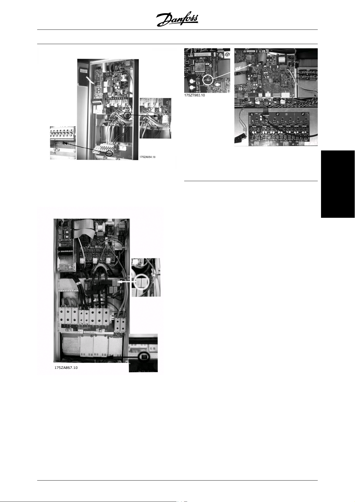
Compact IP 54
VLT 5016 - 5027 200 - 240 V
VLT 5032 - 5062 380 - 500 V
VLT
®
5000 Design Guide
All enclosure types
VLT 5122-5552 380 - 500 V
Electrical installation
Compact IP 54
VLT 5072 - 5102 380 - 500 V
MG.52.B2.02 - VLT
®
is a registered Danfoss trademark 83
Page 85

VLT
®
5000 Design Guide
Serial communication
Protocols
Telegram Traffic
Control and response telegrams
Telegram traffic in a master-slave SYSTEM is controlled by the master. A maximum of 31 slaves can be
connected to a master, unless repeaters are used. If
repeaters are used, a maximum of 126 slaves can be
connected to a master.
The master constantly sends telegrams addressed to
the slaves and waits for response telegrams from
them. The slave's response time is a maximum of 50
ms.
Only a slave that has received an error-free telegram,
addressed to that slave can send a response telegram.
dress of the frequency converter (ADR). Then follows
a number of data bytes (variable, depending on the
type of telegram). The telegram is completed by a data
control byte (BCC).
Telegram timing
The communication speed between a master and a
slave depends on the baud rate. The frequency converter's baud rate must be the same as the master's
baud rate and be selected in parameter 501 Bau-
drate.
After a response telegram from the slave, there must
be a pause of at least 2 characters (22 bits) before the
master can send a new telegram. At a baud rate of
9600 baud there must be a pause of at least 2.3 ms.
When the master has completed the telegram, the
slave's response time back to the master will be a
maximum of 20 ms, and there will be pause of at least
2 characters.
Broadcast
A master can send the same telegram simultaneously
to all slaves connected to the bus. During this broadcast communication the slave does not send any response telegrams back to the master as to whether the
telegram has been correctly received. Broadcast communication is set up in address format (ADR), see
Telegram structure.
Content of a character (byte)
Each character transferred begins with a start bit. Then
8 data bits are transferred, corresponding to a byte.
Each character is secured via a parity bit, which is set
at "1" when it reaches parity (i.e. when there is an equal
number of 1's in the 8 data bits and the parity bit in
total). A character is completed by a stop bit, thus consisting of 11 bits in all.
Pause time, min: 2 characters
Response time, min: 2 characters
Response time, max: 20 ms
The time between the individual characters in a telegram may not exceed 2 characters and the telegram
must be completed within 1.5 x nominal telegram time.
At a baud rate of 9600 baud and a telegram length of
16 bytes the telegram will be completed after 27.5
msec.
Telegram length (LGE)
The telegram length is the number of data bytes plus
the address byte ADR plus the data control byte BCC.
Telegram Structure
Each telegram begins with a start character (STX) =
02 Hex, followed by a byte that denotes the length of
the telegram (LGE) and a byte that denotes the ad-
84 MG.52.B2.02 - VLT
The length of telegrams with 4 data bytes is:
LGE = 4 + 1 + 1 = 6 bytes
The length of telegrams with 12 data bytes is:
LGE = 12 + 1 + 1 = 14 bytes
®
is a registered Danfoss trademark
Page 86
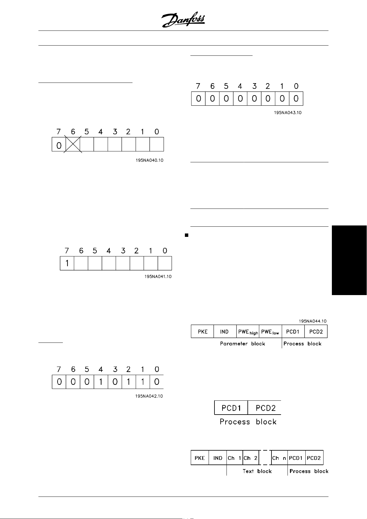
VLT
®
5000 Design Guide
The length of telegrams containing texts is 10+n bytes.
10 represents the fixed characters, while the 'n' is variable (depending on the length of the text).
Frequency converter address (ADR)
Two different address formats are used, with the frequency converter's address range being either 1-31 or
1-126.
1. Address format 1-31
The byte for address range 1-31 has the following pro-
file:
Bit 7 = 0 (address format 1-31 active)
Bit 6 is not used
Bit 5 = 1: Broadcast, address bits (0-4) are
not used
Bit 5 = 0: No Broadcast
Bit 0-4 = Frequency converter address 1-31
Data control byte (BCC)
The data control byte is explained in this example:
Before the first byte in the telegram is received, the
Calculated CheckSum (BCS) is 0.
When
the first byte (02H) has been received:
BCS = BCC EXOR “first byte”
(EXOR = exclusive-or)
BCS = 0 0 0 0 0 0 0 0 (00 H)
EXOR
1. byte
BCC = 0 0 0 0 0 0 1 0 (02H)
= 0 0 0 0 0 0 1 0 (02H)
Each subsequent byte gates with BCS EXOR and produces a new BCC, e.g.:
BCS = 0 0 0 0 0 0 1 0 (02H)
EXOR
2nd byte
BCC = 1 1 0 1 0 1 0 0 (D4H)
= 1 1 0 1 0 1 1 0 (D6H)
2. Address format 1-126
The byte for address range 1 - 126 has the following
profile:
Bit 7 = 1 (address format 1-126 active)
Bit 0-6 = Frequency converter address 1-126
Bit 0-6 = 0 Broadcast
The slave sends the address byte back unchanged in
the response telegram to the master.
Example:
writing to frequency converter address 22 (16H) with
address format 1-31:
Data Character (byte)
The structure of data blocks depends on the type of
telegram. There are three types of telegram, and the
type of telegram applies for both control telegrams
(masterslave) and response telegrams (slavemaster).
The three types of telegram are:
Parameter block, used to transfer parame-
-
ters between master and slave. The data
block is made up of 12 bytes (6 words) and
also contains the process block.
The process block is made up of a data block
-
of four bytes (2 words) and contains:
Control word and reference value
-
Status word and present output fre-
-
quency (from slave to master)
Serial communication
MG.52.B2.02 - VLT
Text block, which is used to read or write texts
-
via the data block.
®
is a registered Danfoss trademark 85
Page 87
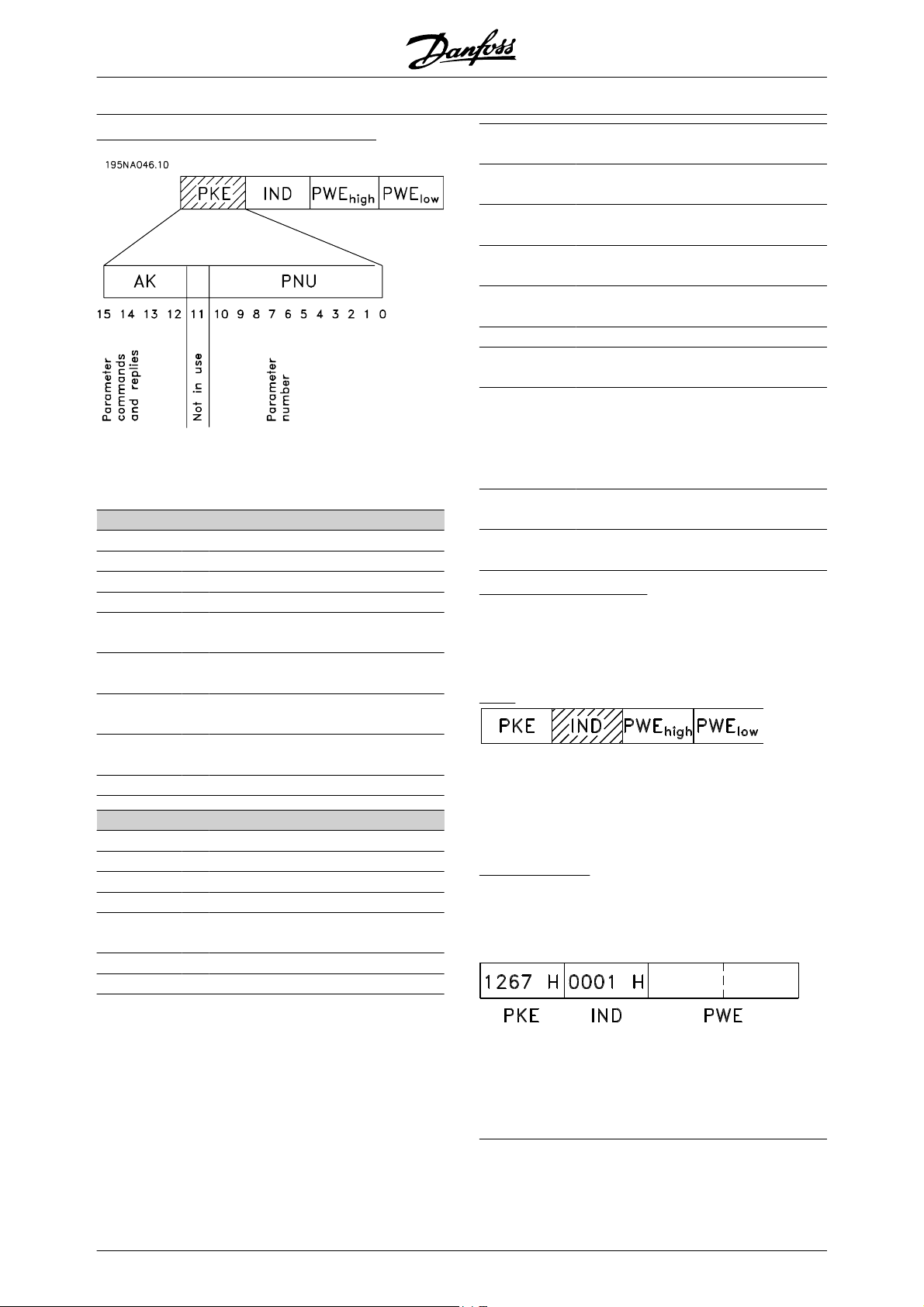
VLT
®
5000 Design Guide
Parameter commands and responses (AK)
Bits no. 12-15 are used to transfer parameter commands from master to slave and the slave's processed
responses back to the master.
Parameter commands masterslave
Bit no.
14 13 12 Parameter command
15
0 0 0 0 No command
0 0 0 1 Read parameter value
0 0 1 0 Write parameter value in RAM
(word)
0 0 1 1 Write parameter value in RAM
(double word)
1 1 0 1 Write parameter value in RAM
and EEprom (double word)
1 1 1 0 Write parameter value in RAM
and EEprom (word)
1 1 1 1 Read/write text
Response slavemaster
Bit no.
Response
15 14 13 12
0 0 0 0 No response
0 0 0 1 Parameter value transferred (word)
0 0 1 0 Parameter value transferred
(double word)
0 1 1 1 Command cannot be performed
1 1 1 1 Text transferred
Response
Fault report
(0111)
0 The parameter number used
does not exist
1 There is no write access to the
defined parameter
2 Data value exceeds
the parameter's limits
3 The sub index used
does not exist
4 The parameter is not the array type
5 The data type does not match the
defined parameter
17 Data change in the defined para-
meter is not possible in the frequency
converter's present mode.
Certain parameters can only be
changed when the motor is turned off
130 There is no bus access to the
defined parameter
131 Data change is not possible because
factory Setup is selected
Parameter number (PNU)
Bits no. 0-10 are used to transfer parameter numbers.
The relevant parameter's function is defined in the parameter description in the section entitled Program-
ming.
Index
Index is
used together with the parameter number to read/
write-access parameters that have an index, e.g. parameter 615 Error code . The index is made up of 2
bytes, one lowbyte and one highbyte, but only the lowbyte is used as an index.
Example - Index:
The first error code (index [1]) in parameter 615 Error
code must be read.
PKE = 1267 Hex (read parameter 615 Error code.)
IND = 0001 Hex - Index no. 1.
If the command cannot be performed the slave sends
this response: 0111 Command cannot be performed
and gives the following fault report in the parameter
value (PWE):
The frequency converter will respond in the parameter
value block (PWE) with a fault code value from 1 - 99.
See Summary of Warnings and Alarms to identify the
fault code.
86 MG.52.B2.02 - VLT
®
is a registered Danfoss trademark
Page 88
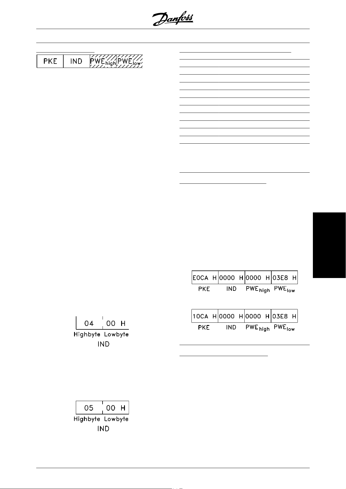
VLT
®
5000 Design Guide
Parameter value (PWE)
The parameter value block consists of 2 words (4 bytes), and
the value depends on the defined command (AK). If
the master prompts for a parameter value, the PWE
block does not contain a value.
If you wish the master to change a parameter value
(write), the new value is written in the PWE block and
sent to the slave.
If the slave responds to a parameter request (read
command), the present parameter value in the PWE
block is transferred and returned to the master.
If a parameter contains not a numerical value, but several data options, e.g. parameter 001 Language where
[0] corresponds to English , and [3] corresponds to
Danish, the data value is selected by entering the value
in the PWE block. See Example - Selecting a data val-
ue.
Via serial communication it is only possible to read parameters that have data type 9 (text string). Parameter
621 - 635 Nameplate data is data type 9. For example,
in parameter 621 Unit type it is possible to read the unit
size and mains voltage range.
When a text string is transferred (read) the length of
the telegram is variable, as the texts are of different
lengths. The telegram length is defined in the telegram's second byte, known as LGE.
To be able to read a text via the PWE block the parameter command (AK) must be set to 'F' Hex.
Data types supported by frequency converter:
Data types
Description
3 Integer 16
4 Integer 32
5 Unsigned 8
6 Unsigned 16
7 Unsigned 32
9 Text string
10 Byte string
13 Time difference
33 Reserved
35 Bit sequence
Unsigned means that there is no operational sign in
the telegram.
Example - Write a parameter value:
Parameter 202 Output frequency high limit, f
MAX
to be
changed to 100 Hz. The value must be recalled after
a mains failure, so it is written in EEPROM.
PKE = E0CA Hex - Write for parameter 202
Output frequency high limit, f
MAX
IND = 0000 Hex
PWE
PWE
= 0000 Hex
HIGH
= 03E8 Hex - Data value 1000, cor-
LOW
responding to 100 Hz, see conversion.
Serial communication
The index character is used to indicate whether it is a
read or write command.
In a read command the index must have the following
format:
Some frequency converters have parameters to which
a text may be written. To be able to write a text via the
PWE block the parameter command (AK) must be set
to 'F' Hex.
For a write command the text must have the following
format:
The response from the slave to the master will be:
Example - Selection of a data value:
You wish to select kg/hour [20] in parameter 416 Proc-
ess units. The value must be recalled after a mains
failure, so it is written in EEPROM.
PKE = E19F Hex - Write for parameter 416
Process units
IND = 0000 Hex
PWE
PWE
= 0000 Hex
HIGH
= 0014 Hex - Select data option kg/
LOW
hour [20]
MG.52.B2.02 - VLT
®
is a registered Danfoss trademark 87
Page 89
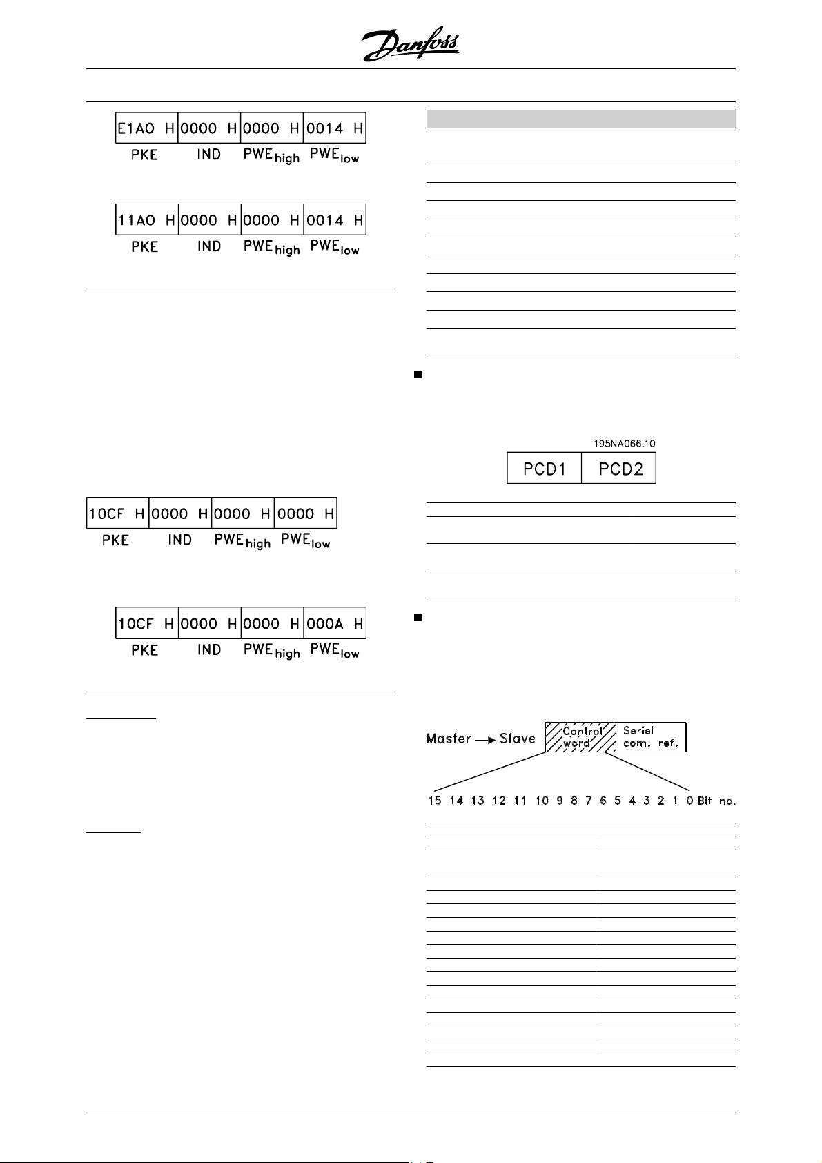
The response from the slave to the master will be:
Example - Reading a parameter value:
The value in parameter 207 Ramp up time 1 is required.
The master sends the following request:
PKE = 10CF Hex - read parameter 207 Ramp
up time 1
IND = 0000 Hex
®
VLT
5000 Design Guide
Conversion table
Conversion
index
Conversion
factor
74 0.1
2 100
1 10
0 1
-1 0.1
-2 0.01
-3 0.001
-4 0.0001
-5 0.00001
Process Words
The block of process words is divided into two blocks
of 16 bits, which always occur in the defined sequence.
PWE
PWE
= 0000 Hex
HIGH
= 0000 Hex
LOW
If the value in parameter 207 Ramp-up time 1 is 10 sec., the
response from the slave to the master will be:
Conversion:
Under the section entitled Factory Settings the various
attributes of each parameter are displayed. As a parameter value can only be transferred as a whole
number, a conversion factor must be used to transfer
decimals.
Example:
Parameter 201 Output frequency, low limit f
MIN
has a
conversion factor of 0.1. If you wish to preset the minimum frequency to 10 Hz, the value 100 must be
transferred, as a conversion factor of 0.1 means that
the value transferred is multiplied by 0.1. The value
100 will thus be perceived as 10.0.
PCD 1 PCD 2
Control telegram
(master ⇒ slave)
Control telegram
(slave ⇒ master)
Control word Reference-
value
Status word Present outp.
frequency
Control Word According to FC Profile
To select FC protocol in the control word, parameter
512 Telegram Profile must be set to FC protocol [1].
The control word is used to send commands from a
master (e.g. a PC) to a slave (frequency converter).
Bit Bit = 0 Bit =1
00 Preset reference choise lsb
01 Preset reference choise
msb
02 DC brake Ramp
03 Coasting Enable
04 Quick stop Ramp
05 Freeze output Ramp enable
06 Ramp stop Start
07 No function Reset
08 No function Jog
09 Ramp 1 Ramp 2
10 Data not valid Valid
11 No function Relay 01 activated
12 No function Relay 04 activated
13 Choice of Setup (lsb)
14 Choice of Setup (msb)
15 No function Reversing
88 MG.52.B2.02 - VLT
®
is a registered Danfoss trademark
Page 90

VLT
®
5000 Design Guide
Bit 00/01:
Bit 00/01 is used to select between the two pre-programmed references (parameters 215-218 Preset ref-
erence) according to the following table:
Preset ref. Parameter Bit 01 Bit 00
1 215 0 0
2 216 0 1
3 217 1 0
4 218 1 1
NB!
In parameter 508 Selection of preset reference a selection is made to define how
Bit 00/01 gates with the corresponding
function on the digital inputs.
Bit 02, DC brake:
Bit 02 = '0' leads to DC braking and stop. Braking current and duration are set in parameters 125 and 126.
Bit 02 = '1' leads to ramping.
Bit 03, Coasting stop:
Bit 03 = '0' causes the frequency converter to immediately "let go" of the motor (the output transistors are
"shut off"), so that it coasts to a standstill.
Bit 03 = '1' causes the frequency converter to be able
start the motor if the other starting conditions have
been fulfilled. Note: In parameter 502 Coasting stop a
selection is made to define how Bit 03 gates with the
corresponding function on a digital input.
Bit 04, Quick stop:
Bit 04 = '0' causes a stop, in which the motor's speed
is ramped down to stop via parameter 212 Quick stop
ramp-down time.
Bit 05, Freeze output frequency:
Bit 05 = '0' causes the present output frequency (in Hz)
to freeze. The frozen output frequency can now only
be changed by means of the digital inputs programmed to Speed up and Speed down.
NB!
If Freeze output is active, the frequency
converter cannot be stopped via Bit 06
Start or via a digital input. The frequency
converter can only be stopped by the following:
• Bit 03 Coasting stop
• Bit 02 DC braking
•
Digital input programmed to DC
braking, Coasting stop or Reset
and coasting stop.
Serial communication
MG.52.B2.02 - VLT
®
is a registered Danfoss trademark 89
Page 91
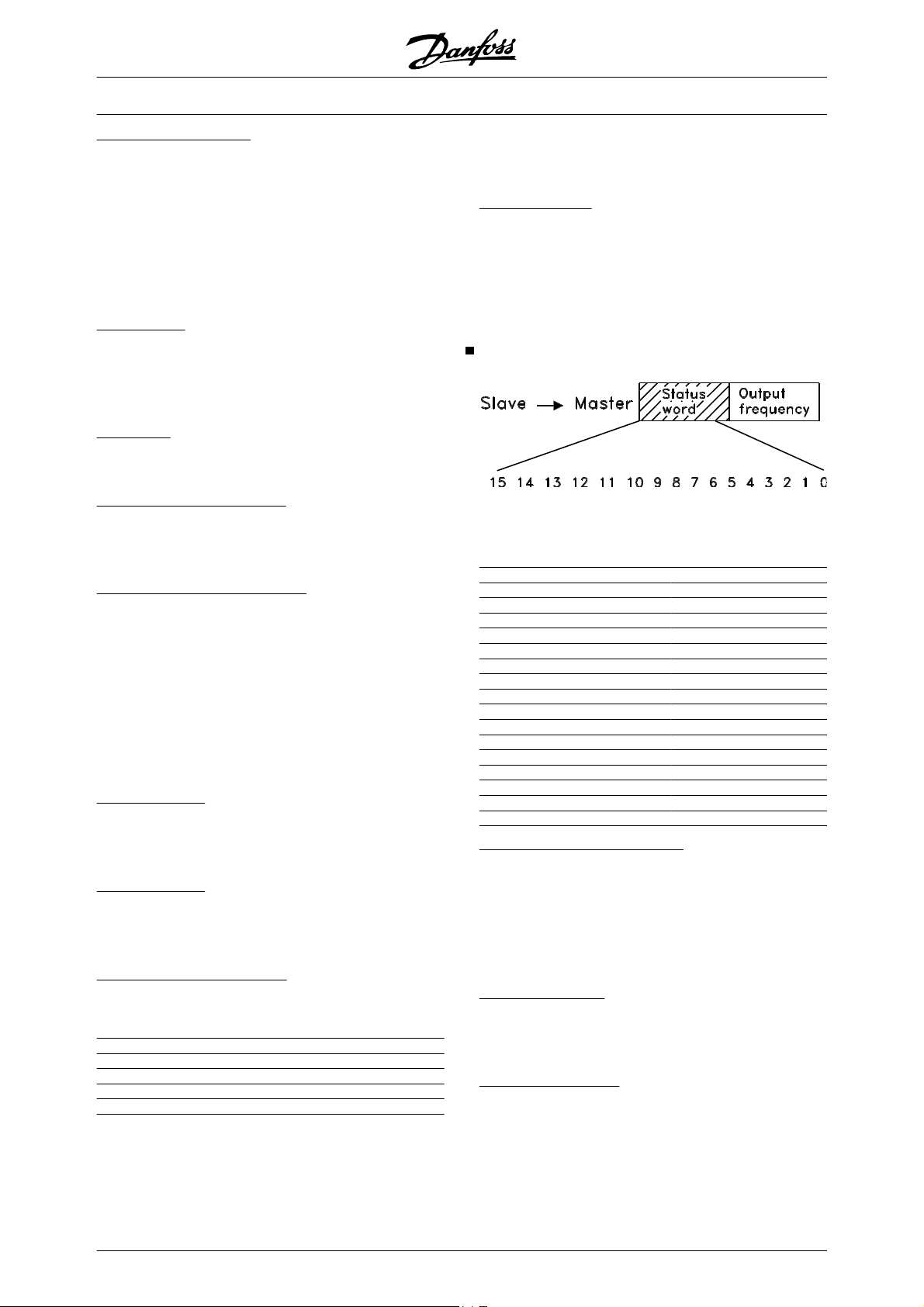
VLT
®
5000 Design Guide
Bit 06, Ramp stop/start:
Bit 06 = '0' causes a stop, in which the motor's speed
is ramped down to stop via the selected ramp down
parameter.
Bit 06 = '1' causes the frequency converter to be able
to start the motor, if the other starting conditions have
been fulfilled. Note: In parameter 505 Start a selection
is made to define how Bit 06 Ramp stop/start gates
with the corresponding function on a digital input.
Bit 07, Reset:
Bit 07 = '0' does not cause a reset.
Bit 07 = '1' causes the reset of a trip. Reset is activated
on the signal's leading edge, i.e. when changing from
logic '0' to logic '1'.
Bit 08, Jog:
Bit 08 = '1' causes the output frequency to be determined by parameter 213 Jog frequency.
Bit 09, Selection of ramp 1/2:
Bit 09 = “0” means that ramp 1 is active (parameters
207/208). Bit 09 = “1” means that ramp 2 (parameters
209/210) is active.
Bit 10, Data not valid/Data valid:
Is used to tell the frequency converter whether the
control word is to be used or ignored. Bit 10 = '0' causes the control word to be ignored, Bit 10 = '1' causes
the control word to be used. This function is relevant,
because the control word is always contained in the
telegram, regardless of which type of telegram is used,
i.e. it is possible to turn off the control word if you do
not wish to use it in connection with updating or reading
parameters.
Bit 11, Relay 01:
Bit 11 = "0" Relay not activated.
Bit 11 = "1" Relay 01 activated, provided Control word
bit has been chosen in parameter 323.
Bit 12, Relay 04:
Bit 12 = "0" Relay 04 has not been activated.
Bit 12 = "1" Relay 04 has been activated, provided
Control word bit has been chosen in parameter 326.
Bit 13/14, Selection of Setup:
Bits 13 and 14 are used to choose from the four menu
Setups according to the following table:
Setup Bit 14 Bit 13
1 0 0
2 0 1
3 1 0
411
The function is only possible when Multi-Setups is selected in parameter 004 Active Setup .
Note: I parameter 507 Selection of Setup a selection is
made to define how Bit 13/14 gates with the corresponding function on the digital inputs.
Bit 15 Reversing:
Bit 15 = '0' causes no reversing.
Bit 15 = '1' causes reversing.
Note: In the factory setting reversing is set to digital in
parameter 506 Reversing. Bit 15 only causes reversing
when either Ser. communication, Logic or or Logic
and is selected.
Status Word according to FC Profile
The status word is used to inform the master (e.g. a
PC) of the slave's (frequency converter) mode. SlaveMaster.
Bit Bit = 0 Bit =1
00 Control not ready Ready
01 VLT not ready Ready
02 Coasting Enable
03 No fault Trip
04 Reserved
05 Reserved
06 Reserved
07 No warning Warning
08 Speed ref. Speed = ref.
09 Local control Bus control
10 Out of range Frequency OK
11 Not running Running
12 Brake test OK Brake test failed
13 Voltage OK Above limit
14 Torque OK Above limit
15 Thermal warning
Bit 00, Control not ready/ready:
Bit 00 = '0' means that the frequency converter has
tripped.
Bit 00 = '1' means that the frequency converter controls
are ready, but that the power component is not necessarily receiving any power supply (in case of external 24 V supply to controls).
Bit 01, Drive ready:
Bit 01 = '1'. The frequency converter is ready for operation, but there is an active coasting command via
the digital inputs or via serial communication.
Bit 02, Coasting stop:
Bit 02 = '0'. The frequency converter has released the
motor.
Bit 02 = '1'. The frequency converter can start the motor when a start command is given.
90 MG.52.B2.02 - VLT
®
is a registered Danfoss trademark
Page 92

VLT
®
5000 Design Guide
Bit 03, No trip/trip:
Bit 03 = '0' means that the frequency converter is not
in fault mode.
Bit 03 = '1' means that the frequency converter is tripped, and that it needs a reset signal for operation to be
reestablished.
Bit 04, Not used:
Bit 04 is not used in the status word.
Bit 05, Not used:
Bit 05 is not used in the status word.
Bit 06, Not used:
Bit 06 is not used in the status word.
Bit 07, No warning/warning:
Bit 07 = '0' means that there are no warnings.
Bit 07 = '1' means that a warning has occurred.
Bit 08, Speed ref/speed = ref.:
Bit 08 = '0' means that the motor is running, but that
the present speed is different from the preset speed
reference. It might, for example, be the case while the
speed is being ramped up/down during start/stop.
Bit 08 = '1' means that the motor's present speed is the
same as the preset speed reference.
Bit 09, Local operation/serial communication control:
Bit 09 = '0' means that [STOP/RESET] is activated on
the control unit, or that Local control in parameter 002
Local/remote operation is selected. It is not possible to
control the frequency converter via serial communication.
Bit 09 = '1' means that it is possible to control the frequency converter via serial communication.
Bit 10, Outside frequency range:
Bit 10 = '0', if the output frequency has reached the
value in parameter 201 Output frequency low limit or
parameter 202 Output frequency high limit. Bit 10 = "1"
means that the output frequency is within the defined
limits.
Bit 11, Running/not running:
Bit 11 = '0' means that the motor is not running.
Bit 11 = '1' means that the frequency converter has a
start signal or that the output frequency is greater than
0 Hz.
Bit 12, Brake test:
Bit 12 = '0' means brake test OK.
Bit 12 = '1' means brake test failed.
Bit 13, Voltage warning high/low:
Bit 13 = '0' means that there are no voltage warnings.
Bit 13 = '1' means that the DC voltage in the frequency
converter's intermediate circuit is too low or too high.
Bit 14, Torque OK/ above limit:
Bit 14 = '0' means that the motor current is lower than
the torque limit selected in parameter 221.
Bit 14 = '1' means that the the torque limit in parameter
221 has been exceeded.
Bit 15, Thermal warning:
Bit 15 = '0' means that there is no thermal warning.
Bit 15 = '1' means that the temperature limit has been
exceeded either in the motor, in the frequency converter, or from a thermistor connected to an analog
input.
Control word according to Fieldbus Profile
To select Profidrive in the control word, parameter 512
Telegram Profile must be set to Profidrive [0].
The control word is used to send commands from a
master (e.g. a PC) to a slave (frequency converter).
Master ⇒ Slave.
Bit Bit = 0 Bit =1
00 OFF 1 ON 1
01 OFF 2 ON 2
02 OFF 3 ON 3
03 Coasting stop
04 Quick stop
05 Freeze outp. freq.
06 Ramp stop Start
07 Reset
08 Bus jog 1
09 Bus jog 2
10 Data not valid Data not valid
11 Slow down
12 Catch-up
13 Select Setup (lsb)
14 Select Setup (msb)
15 Reversing
Bit 00-01-02, OFF1-2-3/ON1-2-3:
Bit 00-01-02 = '0' causes ramp stop, which uses the
ramp time in parameters 207/208 or 209/210.
If Relay 123 is selected in parameter 323 Relay out-
put, the output relay will be activated when the output
frequency is 0 Hz.
Bit 00-01-02 = '1' means that the frequency converter
can start the motor if the other starting conditions are
fulfilled.
Bit 03, Coasting stop:
See description under Control word according to FC
protocol.
Serial communication
MG.52.B2.02 - VLT
®
is a registered Danfoss trademark 91
Page 93

VLT
®
5000 Design Guide
Bit 04, Quick stop:
See description under Control word according to FC
protocol.
Bit 05, Freeze output frequency:
See description under Control word according to FC
protocol.
Bit 06, Ramp stop/start:
See description under Control word according to FC
protocol.
Bit 07, Reset:
See description under Control word according to FC
protocol.
Bit 08, Jog 1:
Bit 08 = "1" means that the output frequency is determined by parameter 09 Bus jog 1.
Bit 09, Jog 2:
Bit 09 = "1" means that the output frequency is determined by parameter 510 Bus jog 2.
Bit 10, Data not valid/Data valid:
See description under Control word according to FC
protocol.
Bit 11, Slow-down:
Used to reduce the speed reference by the value in
parameter 219 Catch-up/slow-down reference.
Bit 11 = '0' does not cause any change to the reference.
Bit 11 = '1' means that the reference is reduced.
Bit 12, Catch-up:
Used to increase the speed reference by the value in
parameter 219 Catch-up/slow-down reference.
Bit 12 = '0' does not cause any change to the reference.
Bit 12 = '1' means that the reference is increased.
If both Slow down and Catch-up are activated (Bits 11
and 12 = "1"), slow down has the highest priority, i.e.
that the speed reference is reduced.
Bit 13/14, Selection of Setup:
See description under Control word according to FC
protocol.
Bit 15 Reversing:
See description under Control word according to FC
protocol.
Status word according to Fieldbus Profile
The status word is used to inform the master (e.g. a
PC) of the slave's (frequency converter) mode. SlaveMaster.
Bit Bit = 0 Bit =1
00 Control ready
01 Drive ready
02 Coasting stop
03 No trip Trip
04 ON 2 OFF 2
05 ON 3 OFF 3
06 Start enable Start disable
07 Warning
08 Speed ref.
Speed =ref.
09 Local control Ser. communi.
10 Outside
frequency range
Frequency limit
OK
11 Motor running
12
13 Voltage warn.
14 Current limit
15 Thermal warn.
Bit 00, Control not ready/ready:
Bit 00 = '0' means that the Bit 00, 01 or 02 in the control
word are '0' (OFF1, OFF2 or OFF3) or the frequency
converter is not ready for operation.
Bit 00 = '1' means that the frequency converter is ready
for operation.
Bit 01, Drive ready:
See description under Status word according to FC
protocol.
Bit 02, Coasting stop:
Bit 02 = '0' means that Bits 00, 02 or 03 in the control
word are "0" (OFF1, OFF3 or Coasting stop).
Bit 02 = '1' means that Bits 00, 01, 02 and 03 in the
control word are "1", and that the frequency converter
has not tripped.
Bit 03, No trip/trip:
See description under Status word according to FC
protocol.
Bit 04, ON 2/OFF 2:
Bit 04 = '0' means that Bit 01 in the control word = '1'.
Bit 04 = '1' means that Bit 01 in the control word = '0'.
92 MG.52.B2.02 - VLT
®
is a registered Danfoss trademark
Page 94

VLT
®
5000 Design Guide
Bit 05, ON 3/OFF 3:
Bit 05 = '0' means that Bit 02 in the control word = '1'.
Bit 05 = '1' means that Bit 02 in the control word = '0'.
Bit 06, Start enable/start disable:
Bit 06 = '1' after reset of a trip, after activation of OFF2
or OFF3 and after connection of mains voltage. Start
disable is reset by setting Bit 00 in the control word to
'0', and Bit 01, 02 and 10 are set to '1'.
Bit 07, Warning:
See description under Status word according to FC
protocol.
Bit 08, Speed:
See description under Status word according to FC
protocol.
Bit 09, No warning/warning:
See description under Status word according to FC
protocol.
Bit 10, Speed ref/speed = ref.:
See description under Status word according to FC
protocol.
Bit 11, Running/not running:
See description under Status word according to FC
protocol.
It is possible to change the direction of rotation via the
serial reference. This is done by converting the binary
reference value to 2' complement. See example.
Example - Control word and serial communication ref.:
The frequency converter is to receive a start command
and the reference is to be set to 50% (2000 Hex) of the
reference range.
Control word = 047F Hex ⇒ Start command.
Reference = 2000 Hex ⇒ 50% reference.
The frequency converter is to receive a start command
and the reference is to be set to -50% (-2000 Hex) of
the reference range.
The reference value is first converted to 1' complement, and then 1 is added binarily to obtain 2' complement:
2000 Hex 0010 0000 0000 0000 0000
1' complement 1101 1111 1111 1111 1111
2' complement 1110 0000 0000 0000 0000
+ 1
Control word = 047F Hex ⇒ Start command.
Reference = E000 Hex ⇒ -50% reference.
Bit 13, Voltage warning high/low:
See description under Status word according to FC
protocol.
Bit 14, Current limit:
See description under Status word according to FC
protocol.
Bit 15, Thermal warning:
See description under Status word according to FC
protocol.
Serial communication reference
The serial communication reference is transferred to
the frequency converter as a 16-bit word. The value is
transferred in whole numbers 0 - ±32767 (±200%).
16384 (4000 Hex) corresponds to 100%.
The serial communication reference has the following
format: 0-16384 (4000 Hex) ≅ 0-100% (Par. 204 Min-
imum ref. - Par. 205 Maximum ref.).
Serial communication
Present output frequency
The value of the frequency converter's present output
frequency is transferred as a 16-bit word. The value is
transferred as whole numbers 0 - ±32767 (±200%).
16384 (4000 Hex) corresponds to 100%.
Output frequency has the following format:
0-16384 (4000 Hex) • 0-100% (Par. 201 Output fre-
quency low limit - Par. 202 Output frequency high limit).
Example - Status word and current output frequency:
The master receives a status message from the frequency converter that the current output frequency is
50% of the output frequency range.
Par. 201 Output frequency low limit = 0 Hz
Par. 202 Output frequency high limit = 50 Hz
Status word = 0F03 Hex.
MG.52.B2.02 - VLT
®
is a registered Danfoss trademark 93
Page 95

Output frequency = 2000 Hex ⇒ 50% of the frequency
range, corresponding to 25 Hz.
VLT
®
5000 Design Guide
94 MG.52.B2.02 - VLT
®
is a registered Danfoss trademark
Page 96
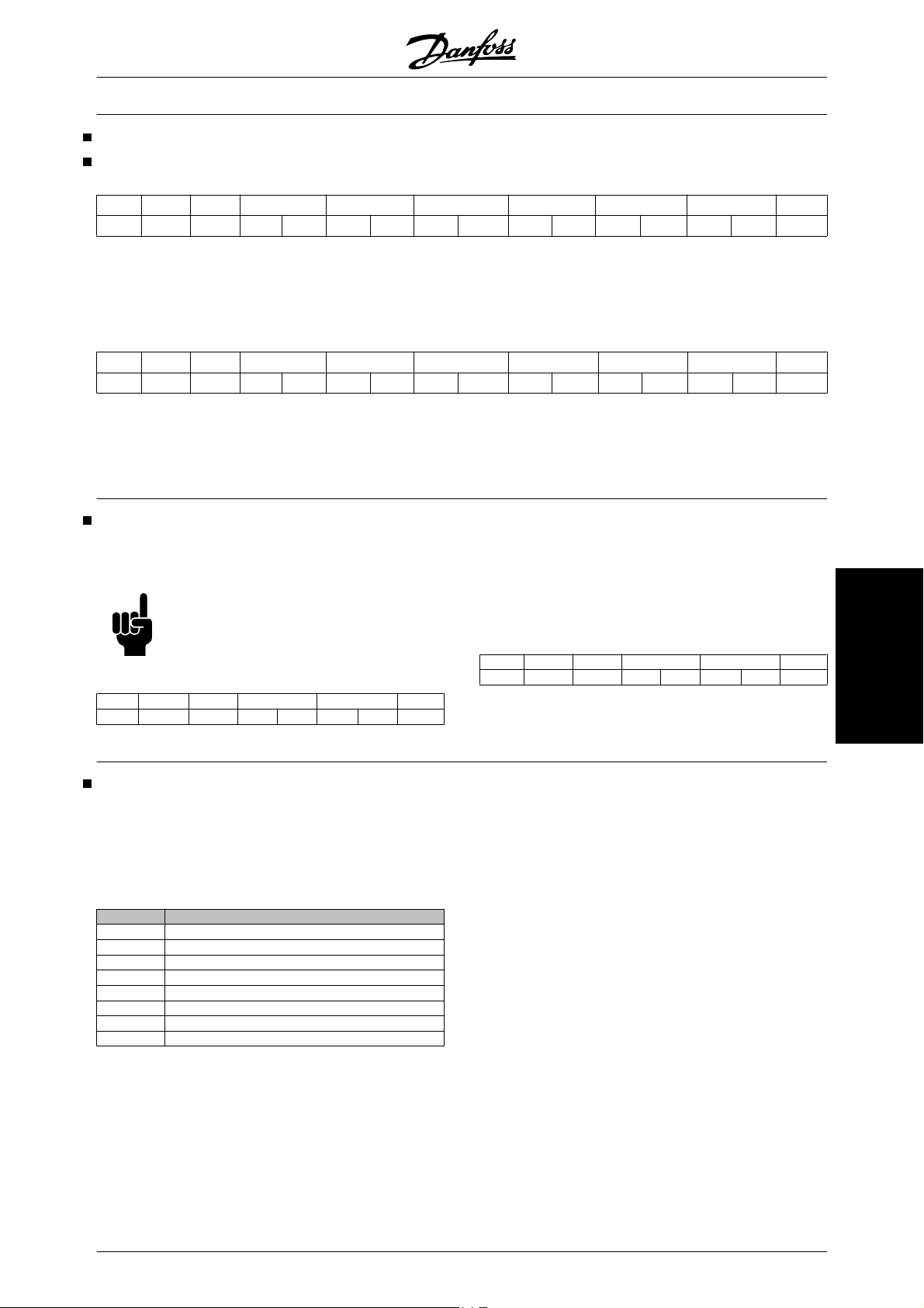
VLT
®
5000 Design Guide
Telegram example
Example 1: For Controlling the Drive and Reading
This telegram reads parameter 520, motor current.
Telegram to the frequency converter:
Parameters
lge adr pke ind pwe, high pwe, low pcd 1 pcd 2 bcc
stx
02 0E 01 12 08 00 00 00 00 00 00 00 00 00 00 17
All numbers are in hex format.
The response from the frequency converter will correspond to the command above, but pwe,high and
current is 5.24 A then the value coming from the frequency converter is 524.
Response from the frequency converter:
pwe,low will contain the actual value of parameter 520
multiplied by 100. This means that if the actual output
lge adr pke ind pwe, high pwe, low pcd 1 pcd 2 bcc
stx
02 0E 01 22 08 00 00 00 00 02 0C 06 07 00 00 28
All numbers are in hex format.
Pcd 1 and pcd 2 from example 2 can be used and
sible to control the drive and read the current at the
same time.
added to the example which means that it will be pos-
Example 2: Only for Controlling the Drive
This telegram sets the control word to 047C Hex (Start
command) with a speed reference of 2000 Hex (50%).
All numbers are in hex format.
The response from the frequency converter gives information of the status of the drive when it received the
command. By sending the command again, the pcd1
NB!
Parameter 512 is set to FC Drive.
will change to the new status.
Response from the frequency converter:
Telegram to the frequency converter:
stx lge adr pcd 1 pcd 2 bcc
02 06 04 04 7C 20 00 58
Read parameter description elements
With Read Parameter Description Elements it is possible to read the characteristics of a parameter which
could be eg. Name, Default value, conversion, etc.
The table below shows the available parameter description elements:
Index Description
1 Basic characteristics
2 No of elements (array types)
4 Unit of measure
6 Name
7 Lower limit
8 Upper limit
20 Default value
21 Additional characteristics
In the following example Read Parameter Description
Elements is chosen on parameter 001, Language, and
the requested element is index 1 Basic characteris-
tics.
stx lge adr pcd 1 pcd 2 bcc
02 06 04 06 07 00 00 01
All numbers are in hex format.
Basic characteristics return a 16 bit value to the master
in PWE
LOW
.
The basic behaviour indicates whether eg. text is available or the parameter is an array as single bit information in the high byte of PWE
LOW
.
The datatype part indicates if a parameter is signed 16,
unsigned 32 in the low byte of PWE
LOW
.
Serial communication
Basis characteristics (index 1):
The Basic characteristics command is split up in two
parts representing basic behaviour and datatype. The
MG.52.B2.02 - VLT
®
is a registered Danfoss trademark 95
Page 97

VLT
®
5000 Design Guide
PWE high basic behaviour:
Bit Description
15 Active parameter
14 Array
13 Parameter value can only be reset
12 Parameter value different from factory setting
11 Text available
10 Additional text available
9 Read only
8 Upper and lower limit not relevant
0-7 Data type
Active parameter is only active when communicating
through Profibus.
Array means that the parameter is an array.
If bit 13 is true, the parameter can only be reset, not
written to.
If bit 12 is true, the parameter value is different from
the factory setting.
Bit 11 indicates that text is available.
Example
Bit 10 indicates that additional text is available. Eg.
parameter 001, Language, contains text for index field
0, English, and for index field 1, German.
If bit 9 is true, the parameter value is read-only and
cannot be changed.
If bit 8 is true, upper and lower limits of the parameter
value are not relevant.
PWE
Dec. Datatype
3 Signed 16
4 Signed 32
5 Unsigned 8
6 Unsigned 16
7 Unsigned 32
9 Visible string
10 Byte string
13 Time difference
33 Reserved
35 Bit sequence
datatype
LOW
In this example, the master reads the Basic characteristics of parameter 001, Language. The following
telegram must be sent to the frequency converter:
STX LGE ADR PKE IND PWE
02 0E 01 40 01 00 01 00 00 00 00 XX XX XX XX XX
STX = 02 Start byte
LGE = 0E Length of remaining telegram
ADR = Sends the frequency converter on Address
PKE =
IND =
STX LGE ADR PKE IND PWE
02 0E 01 30 01 00 01 00 00 04 05 XX XX XX XX XX
PKE = 02 Start byte IND = 0001; 1 indicates that
PWE
= 0405; 04 indicates that Basic behaviour as
LOW
1, Danfoss format
4001; 4 in the PKE field indicates a Read
Parameter Description and 01 indicates parameter number 001, Language
0001; 1 indicates that Basic characteristics
are required.
Basic characteristics are sent
bit 10 corresponds to Additional text. 05 is the
datatype which corresponds to Unsigned 8.
HIGH
PWE
LOW
PCD1 PCD2 BCC
The response from the frequency converter will be:
HIGH
PWE
LOW
PCD1 PCD2 BCC
No of elements (index 2):
This function indicates the Number of elements (array)
of a parameter. The answer to the master will be in
LOW
.
PWE
Conversion and Unit of measurement (index 4):
The Conversion and unit of measurement command
indicates the conversion of a parameter and the unit of
measurement. The answer to the master will be in
PWE
of PWE
PWE
. The conversion index will be in the high byte
LOW
and the unit index will be in the low byte of
LOW
. Note that conversion index is signed 8 and
LOW
unit index is unsigned 8, see tables below.
The unit index defines the “Unit of measure”. The conversion index defines how the value should be scaled
to get the basic representation of the “Unit of measure”. Basic representation is where conversion index
equals “0”.
Example:
A parameter has a “unit index” of 9 and a “conversion
index” of 2. The raw (integer) value read is 23. This
means that we have a parameter of the unit “Power”
and the raw value should be multiplied by 10 to the
power of 2 and the unit is W. 23 x 102 = 2300 W
Table for conversion and unit of measurement
96 MG.52.B2.02 - VLT
®
is a registered Danfoss trademark
Page 98
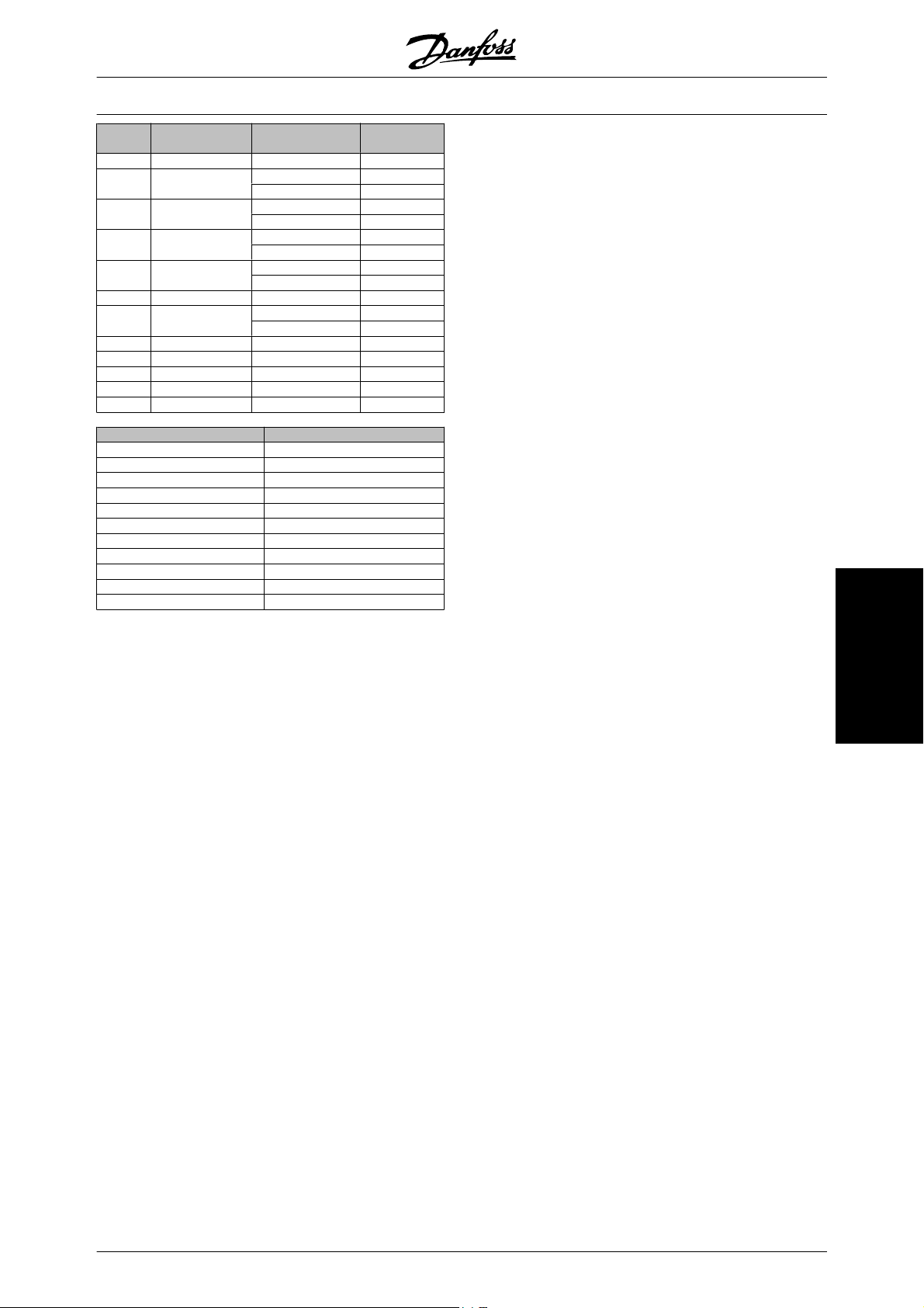
VLT
®
5000 Design Guide
Unit index
0 Dimension less 0
4 Time s 0
8 Energy j 0
9 Power W 0
11 Speed 1/s 0
16 Torque Nm 0
17 Temperature K 0
21 Voltage V 0
22 Current A 0
24 Ratio % 0
27 Relative change % 0
28 Frequency Hz 0
Conversion index Conversion factor
Unit of measure Designation Conversion
h 74
kWh
kW 3
1/min (RPM) 67
°C 100
0 1
1 10
2 100
3 1000
-1 0.1
-2 0.01
-3 0.001
67 1/60
74 3600
75 3600000
100 1
index
Serial communication
MG.52.B2.02 - VLT
®
is a registered Danfoss trademark 97
Page 99
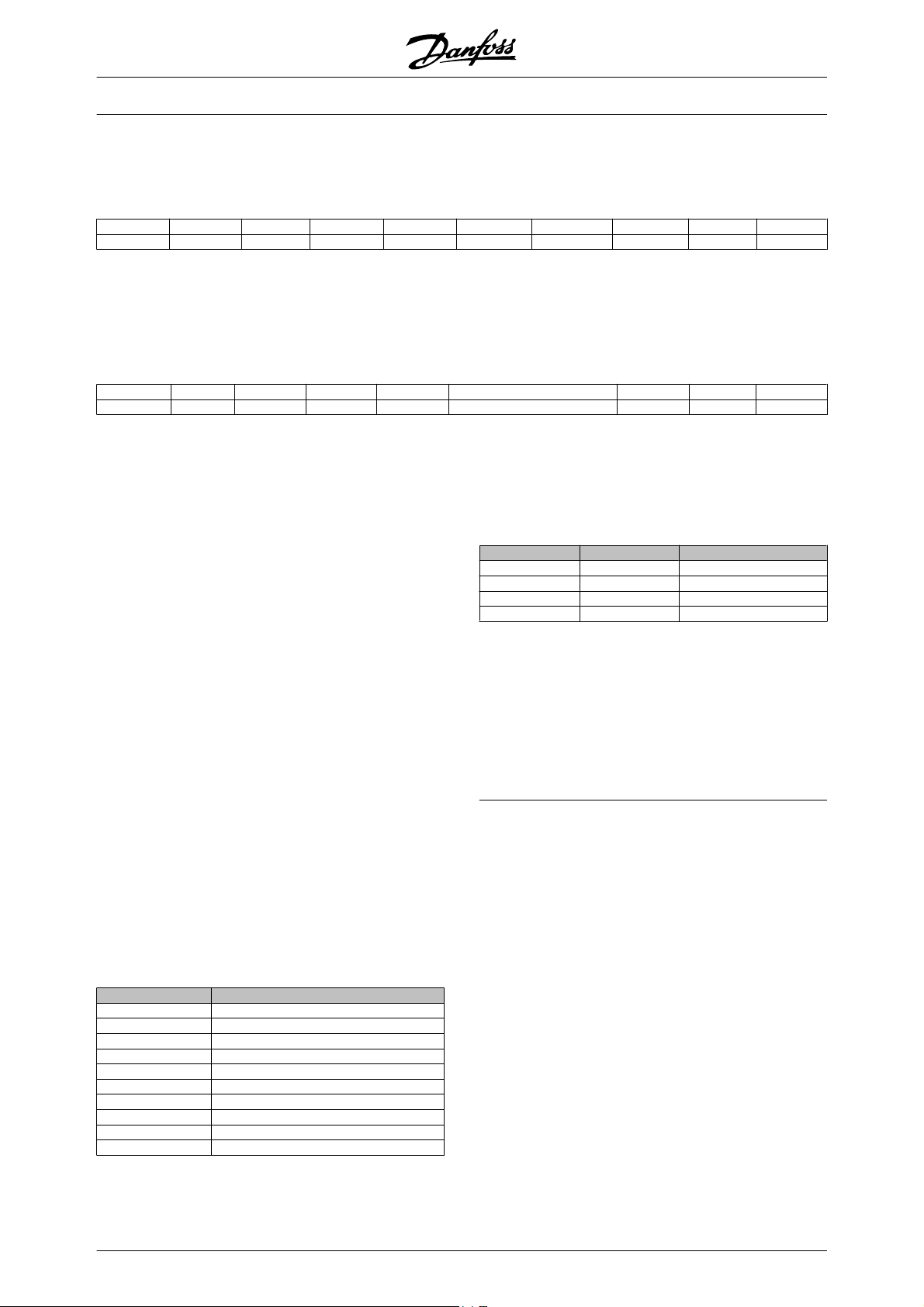
VLT
®
5000 Design Guide
Name (index 6):
The Name returns a string value in ASCII format, containing the name of the parameter.
Example:
STX LGE ADR PKE IND PWE
02 0E 01 40 01 00 06 00 00 00 00 XX XX XX XX XX
STX = 02 Start byte
LGE = 0E Length of remaining telegram
ADR = Sends the frequency converter on Address
PKE =
IND =
STX LGE ADR PKE IND PVA PCD1 PCD2 BCC
02 12 01 30 01 00 06 4C41 4E47 5541 4745 XXXX XXXX XX
PKE =
IND =
PVA = 4C 41 4E 47 55 41 47 45
1, Danfoss format
4001; 4 in the PKE field indicates a Read
Parameter Description and 01 indicates parameter number 001, Language
0006; 6 indicates that Names is required.
3001; 3 are the response for Name and 01
indicates the parameter number 001, Lan-
guage
00 06; 06 indicates that Name is sent.
L A N G U A G E
The parameter value channel is now set up to a visible
string which returns an ASCII character for each letter
in the parameter name.
Lower limit (index 7):
The Lower limit returns the minimum allowed value of
a parameter. The data type of Lower limit is the same
as for the parameter itself.
Upper limit (index 8):
The Upper limit returns the maximum allowed value of
a parameter. The data type of Upper limit is the same
is for the parameter itself.
In this example the master reads the name of parameter 001, Language.
The following telegram must be sent to the frequency
converter:
HIGH
PWE
LOW
PCD1 PCD2 BCC
The response from the frequency converter will be:
If one of bit 0 Special Default Value, bit 1 Special Upper
Limit and bit 2 Special Lower Limit are true, the parameter has power unit depending values.
Bit 7 and 8 indicates the attributes for the LCP access,
see table.
Bit 8 Bit 7 Description
0 0 No access
0 1 Read only
1 0 Read/write
1 1 Write with lock
Bit 9 indicates No bus Access.
Bits 10 and 11 indicates that this parameter can only
be read over the bus.
If bit 13 is true, the parameter cannot be changed while
running.
If bit 15 is true, the parameter is depending on the
power unit.
Default value (index 20):
The Default value returns the default value of a parameter, which is the factory setting. The data type of
Default value is the same as for the parameter itself.
Additional characteristics (index 21):
The command can be used for getting some additional
information on a parameter, eg. No bus Access, Power
Unit dependency, etc.. The Additional characteristics
returns an answer in PWE
. If a bit is logic '1', the
LOW
condition is true according to the table below:
Bit Description
0 Special Default Value
1 Special Upper Limit
2 Special Lower Limit
7 LCP Access LSB
8 LCP Access MSB
9 NoBusAccess
10 Std Bus Read Only
11 Profibus Read Only
13 ChangeRunning
15 PowerUnitDependency
98 MG.52.B2.02 - VLT
®
is a registered Danfoss trademark
Page 100
VLT
®
5000 Design Guide
Additional Text
With this feature it is possible to read additional text if
bit 10, Additional text available, is true in Basic characteristics.
To read out additional text, the parameter command
(PKE) must be set to F hex, see Databytes.
The index-field is used for pointing out which element
to be read. Valid indexes are in the range of 1 through
Example:
In this example, the Master reads additional text in parameter 001, Language. The telegram is set up to read
STX LGE ADR PKE IND PWE
02 0E 01 F0 01 00 01 00 00 00 00 XX XX XX XX XX
STX = 02 Start byte
LGE = 0E Length of the remaining telegram
ADR = Send the VLT frequency converter on Ad-
PKE =
IND = 0001; 1 indicates that text to parameter val-
STX LGE ADR PKE IND PVA PCD1 PCD2 BCC
02 11 01 F0 01 00 01 454E 474C 4953 48 XX XX XX XX XX
PKE =
IND = 0001; 1 indicates that index [1] is sent
PVA = 45 4E 47 4C 49 53 48
dress 1, Danfoss format
F001; F in the PKE field indicates a Read
text and 01 indicates parameter number
001, Language.
ue [0] is required
F001; F is the response for Text transfer and
01 indicates parameter number 001, Lan-
guage.
E N G L I S H
254. The index must be calculated after the following
equation:
Index = Parameter value + 1 (see table below).
Value Index Text
0 1 English
1 2 Deutsch
2 3 Français
3 4 Dansk
4 5 Espanol
5 6 Italiano
datavalue [0] which corresponds to English. The following telegram must be sent to the VLT frequency
converter:
HIGH
PWE
PCD1 PCD2 BCC
LOW
The response from the VLT frequency converter will
be:
The parameter value channel is now set up to a visible
string, which returns an ASCII character for each letter
in the index name.
Serial communication
MG.52.B2.02 - VLT
®
is a registered Danfoss trademark 99
 Loading...