


Contents
VLT® 5000 Series
Safety
Safety regulations 4
Warning against unintended start 5
Installation of mechanical brake 5
Quick Setup
Introduction
Available literature 9
Technical data
General technical data 10
Electrical data 16
Fuses 33
Mechanical dimensions 35
Installation
Mechanical installation 38
Safety earthing 41
Extra protection (RCD) 41
Electrical installation - mains supply 41
Electrical installation - motor cables 42
Connection of motor 42
Direction of motor rotation 42
Electrical installation - brake cable 43
Electrical installation - brake resistor temperature switch 43
Electrical installation - loadsharing 43
Electrical installation - 24 Volt external DC supply 45
Electrical installation - relay outputs 45
Electrical installation - control cables 53
Electrical installation - bus connection 56
Electrical installation - EMC precautions 57
Use of emc-correct cables 60
Electrical installation - earthing of control cables 61
RFI switch 62
3
6
9
10
38
Operation of the frequency converter
Control panel (LCP) 65
Control panel - display 65
Control panel - LEDs 65
Control panel - control keys 66
Quick Setup 68
Parameter selection 68
Menu mode 68
Initialisation to factory setting 70
MG.52.A3.02 - VLT® is a registered Danfoss trademark 1
65

VLT® 5000 Series
Application configuration
Connection examples 72
Setting of parameters 74
Special functions
Local and remote control 77
Control with brake function 78
References - single references 79
References - multi-references 81
Automatic Motor Adaptation, AMA 85
Mechanical brake control 87
PID for process control 89
PID for speed control 90
Quick discharge 91
Flying start 93
Normal/high overload torque control,open loop 94
Programming of Torque limit and stop 94
Programming
Parameters - Operation and Display 96
Parameters - Load and motor 103
Parameters - References and limits 114
Parameters - Inputs and outputs 122
Parameters - Special functions 138
Parameters - Serial communication 152
Parameters - Technical functions and diagnostics 159
72
77
96
Miscellaneous
Trouble-shooting 166
Display - Status messages 167
Warnings and alarms 170
Warnings 171
Index
166
190
2 MG.52.A3.02 - VLT® is a registered Danfoss trademark
VLT® 5000 Series
VLT 5000 Series
Operating Instructions
Software version: 3.9x
These Operating Instructions can be used for all VLT 5000 Series frequency converters with software version
3.9x.
The software version number can be seen from parameter 624.
CE and C-tick labelling do not cover VLT 5001-5062, 525-600 V units.
These Operating Instructions are a tool intended for persons who are to install, operate and program the VLT
5000 Series.
Operating Instructions: Gives instructions in optimum installation, commissioning and service.
Design Guide: Gives all required information for design purposes, and gives a good insight
into the technology, product range, technical data, etc.
Safety
The Operating Instructions including Quick Setup are delivered with the unit.
When reading these Operating Instructions, you will come across different symbols that require special attention.
The symbols used are the following:
Indicates a general warning
NB!
Indicates something to be noted by the
reader
Indicates a high-voltage warning
MG.52.A3.02 - VLT® is a registered Danfoss trademark 3
The voltage of the frequency converter is
dangerous whenever the equipment is
connected to mains. Incorrect installation
of the motor or the frequency converter
may cause damage to the equipment, serious personal injury or death.
Consequently, the instructions in this
manual, as well as national and local rules
and safety regulations, must be complied
with.
Installation in high altitudes:
By altitudes above 2km, please contact
Danfoss Drives regarding PELV
Safety regulations
1. The frequency converter must be disconnected from mains if repair work is to be carried
out. Check that the mains supply has been
disconnected and that the necessary time
has passed before removing motor and
mains plugs.
VLT® 5000 Series
necessary time has expired before removing
motor and mains plugs.
7. Please note that the frequency converter has
more voltage inputs than L1, L2 and L3, when
loadsharing (linking of DC intermediate circuit) and external 24 V DC have been installed. Check that all voltage inputs have been
disconnected and that the necessary time
has passed before repair work is commenced.
2. The [STOP/RESET] key on the control panel
of the frequency converter does not disconnect the equipment from mains and is thus
not to be used as a safety switch.
3. Correct protective earthing of the equipment
must be established, the user must be protected against supply voltage, and the motor
must be protected against overload in accordance with applicable national and local
regulations.
4. The earth leakage currents are higher than
3.5 mA.
5. Protection against motor overload is not included in the factory setting. If this function is
desired, set parameter 128 to data value ETR
trip or data value ETR warning.
Note: The function is initialised at 1.16 x rated
motor current and rated motor frequency. For
the North American market: The ETR functions provide class 20 motor overload protection in accordance with NEC.
6. Do
4 MG.52.A3.02 - VLT® is a registered Danfoss trademark
not remove the plugs for the motor and
main supply while the frequency converter is
connected to mains. Check that the mains
supply has been disconnected and that the
VLT® 5000 Series
Warning against unintended start
1. The motor can be brought to a stop by means
of digital commands, bus commands, references or a local stop, while the frequency
converter is connected to mains.
If personal safety considerations make it necessary to ensure that no unintended start
occurs,
cient.
2. While parameters are being changed, the
motor may start. Consequently,
[STOP/RESET] must always be activated,
following which data can be modified.
3. A motor that has been stopped may start if
faults occur in the electronics of the frequency converter, or if a temporary overload or a
fault in the supply mains or the motor connection ceases.
these stop functions are not suffi-
the stop key
Warning:
Installation of mechanical brake
not connect a mechanical brake to the output from
Do
the frequency converter before the relevant parameters for brake control are parameterised.
(Selection of output in parameter 319, 321, 323 or 326
and cut-in current and frequency in parameter 223 and
225).
Use on isolated mains
See section RFI Switch regarding use on isolated
mains.
It is important to follow the recommendations regarding installation on IT-mains, since sufficient protection
of the complete installation must be observed. Not taking care using relevant monitoring devices for ITmains may result in damage.
Safety
Touching the electrical parts may be fatal - even after the equipment has been disconnected from mains.
Also make sure that other voltage inputs have been disconnected, such as external 24 V DC, load-sharing (linkage
of DC intermediate circuit), as well as the motor connection for kinetic back-up.
VLT 5001 - 5006, 200-240 V: wait at least 4 minutes
VLT 5008 - 5052, 200-240 V: wait at least 15 minutes
VLT 5001 - 5006, 380-500 V: wait at least 4 minutes
VLT 5008 - 5062, 380-500 V: wait at least 15 minutes
VLT 5072 - 5302, 380-500 V: wait at least 20 minutes
VLT 5352 - 5552, 380-500 V: wait at least 40 minutes
VLT 5001 - 5005, 525-600 V wait at least 4 minutes
VLT 5006 - 5022, 525-600 V: wait at least 15 minutes
VLT 5027 - 5062, 525-600 V: wait at least 30 minutes
VLT 5042 - 5352, 525-690 V: wait at least 20 minutes
VLT 5402 - 5602, 525-690 V: wait at least 30 minutes
MG.52.A3.02 - VLT® is a registered Danfoss trademark 5
VLT® 5000 Series
Introduction to Quick Setup
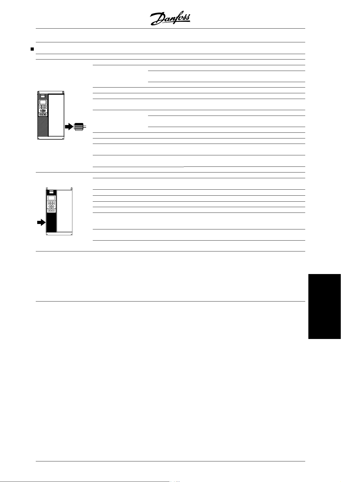
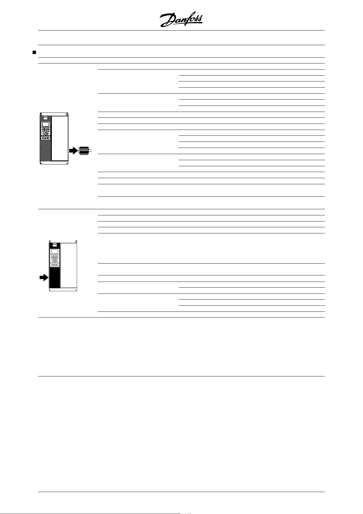
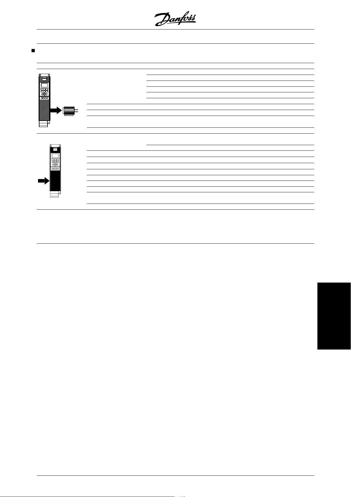
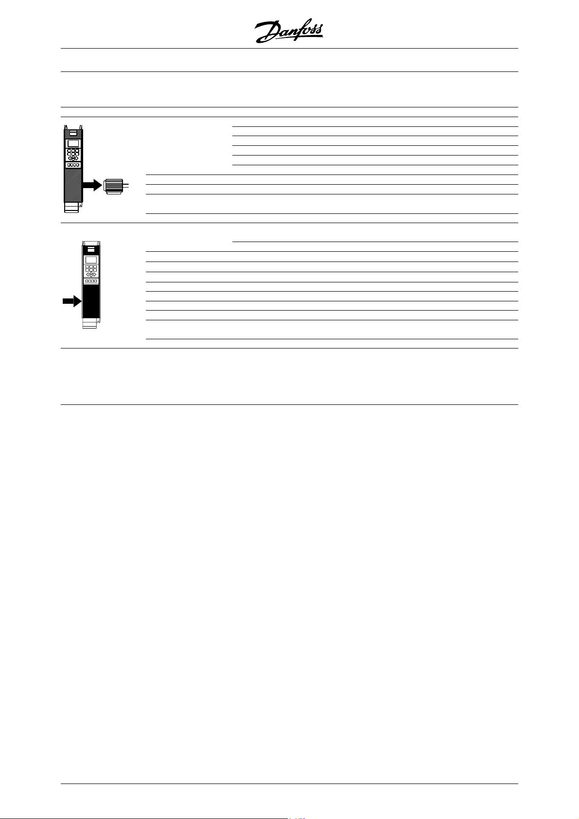
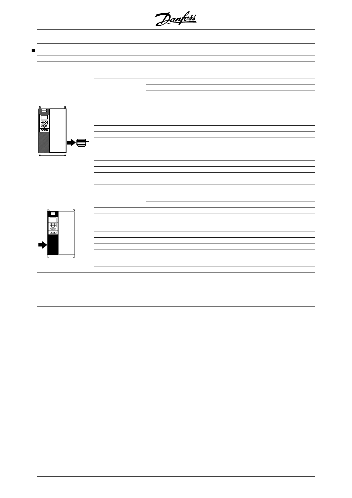
This Quick Setup will guide you through EMC correct
installation of the frequency converter by connecting
power, motor and control wiring (fig. 1). Start/stop of
motor is to be done with the switch.
For VLT 5122 - 5552 380 - 500 V, VLT 5032 - 5052
200 - 240 V AC and VLT 5042-5602, 525-690 V,
please refer to Technical data and Installation regarding
mechanical and electrical installation.
Fig. 1
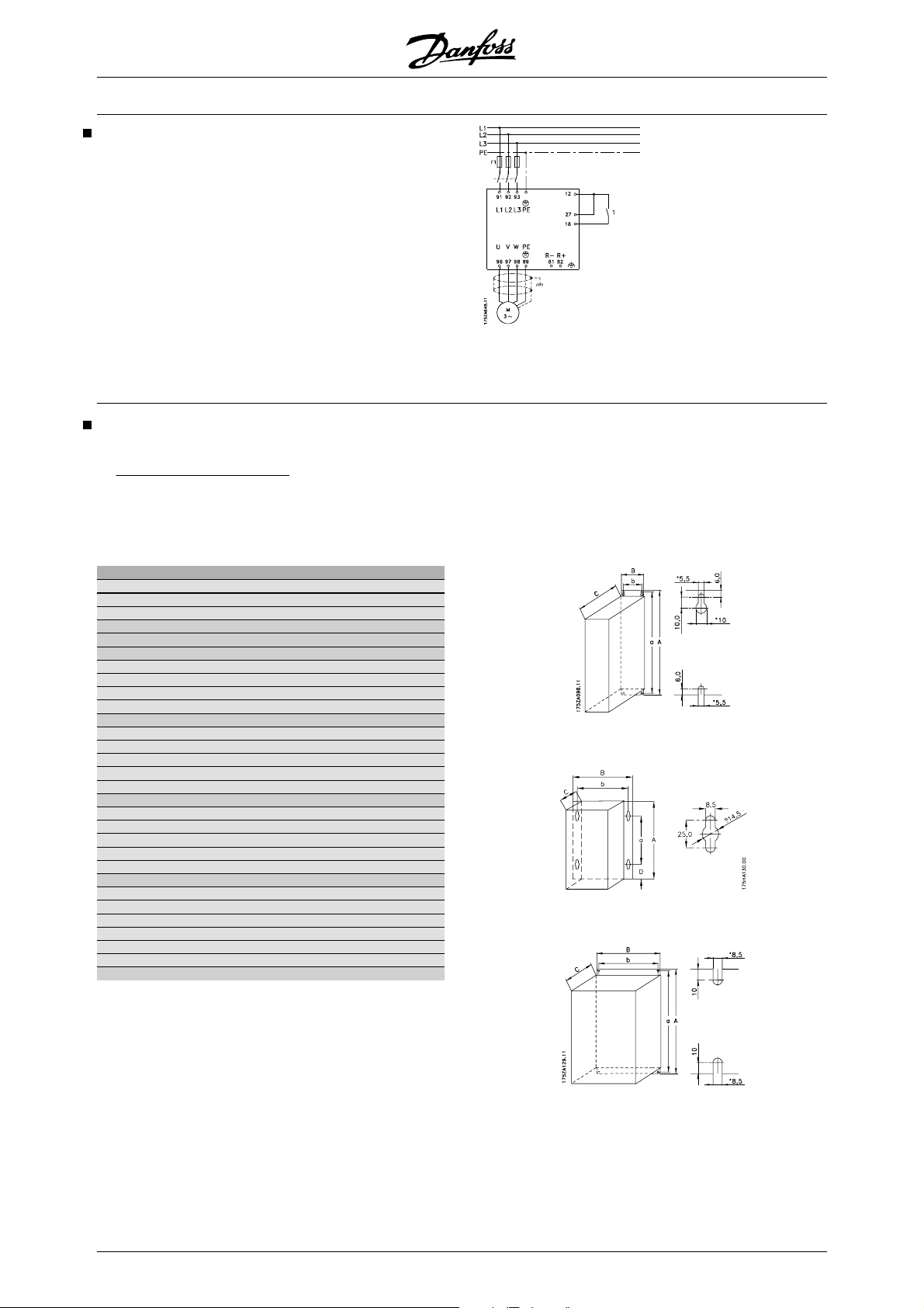
1. Mechanical Installation
VLT 5000 frequency converters allow side-by-side mounting. The necessary cooling demands a free air passage
100 mm above and below the frequency converter (5016-5062 380-500 V, 5008-5027 200-240 V and
of
5016-5062 525-600 V must have 200 mm, 5072-5102, 380-500 V 225 mm).
Drill all holes by using the measurements stated in the table. Please note the difference in unit voltage. Place the
frequency converter on the wall. Tighten up all four screws.
All the below listed measurements are in mm
VLT type A B C a b
Bookstyle IP 20, 200–240 V, (Fig. 2)
5001 - 5003 395 90 260 384 70
5004 - 5006 395 130 260 384 70
Bookstyle IP 20, 380–500 V (Fig. 2)
5001 - 5005 395 90 260 384 70
5006 - 5011 395 130 260 384 70
Compact IP 54, 200–240 V (Fig. 3)
5001 - 5003 460 282 195 260 258
5004 - 5006 530 282 195 330 258
5008 - 5011 810 350 280 560 326
5016 - 5027 940 400 280 690 375
Compact IP 54, 380–500 V (Fig. 3)
5001 - 5005 460 282 195 260 258
5006 - 5011 530 282 195 330 258
5016 - 5027 810 350 280 560 326
5032 - 5062 940 400 280 690 375
5072 - 5102 940 400 360 690 375
Compact IP 20, 200–240 V (Fig. 4)
5001 - 5003 395 220 160 384 200
5004 - 5006 395 220 200 384 200
5008 560 242 260 540 200
5011 - 5016 700 242 260 680 200
5022 - 5027 800 308 296 780 270
Compact IP 20, 380–500 V (Fig. 4)
5001 - 5005 395 220 160 384 200
5006 - 5011 395 220 200 384 200
5016 - 5022 560 242 260 540 200
5027 - 5032 700 242 260 680 200
5042 - 5062 800 308 296 780 270
5072 - 5102 800 370 335 780 330
Fig. 2
Fig. 3
Fig. 4
6 MG.52.A3.02 - VLT® is a registered Danfoss trademark
VLT® 5000 Series
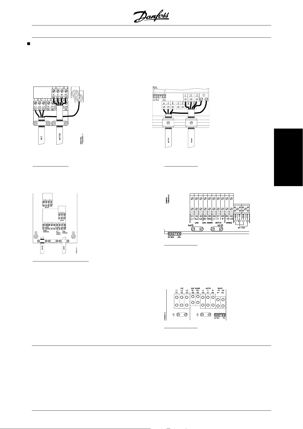
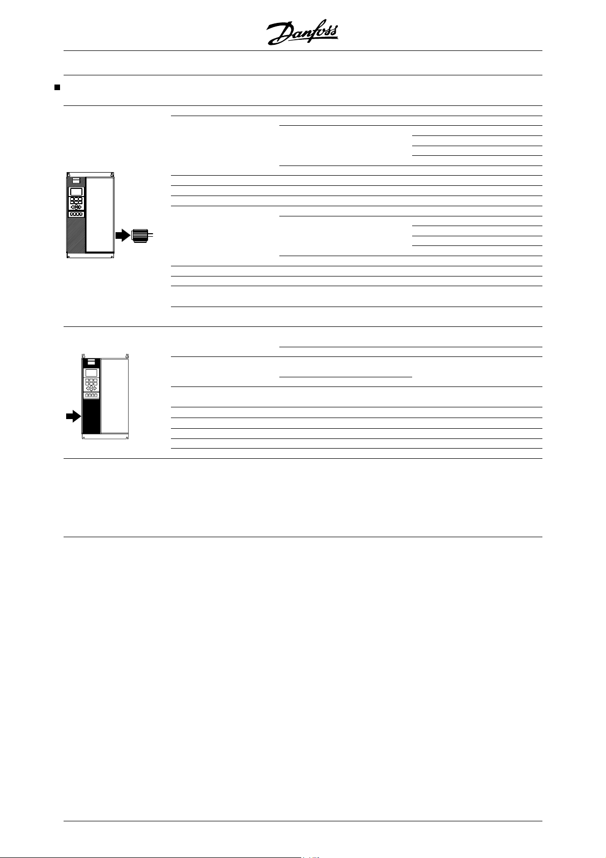
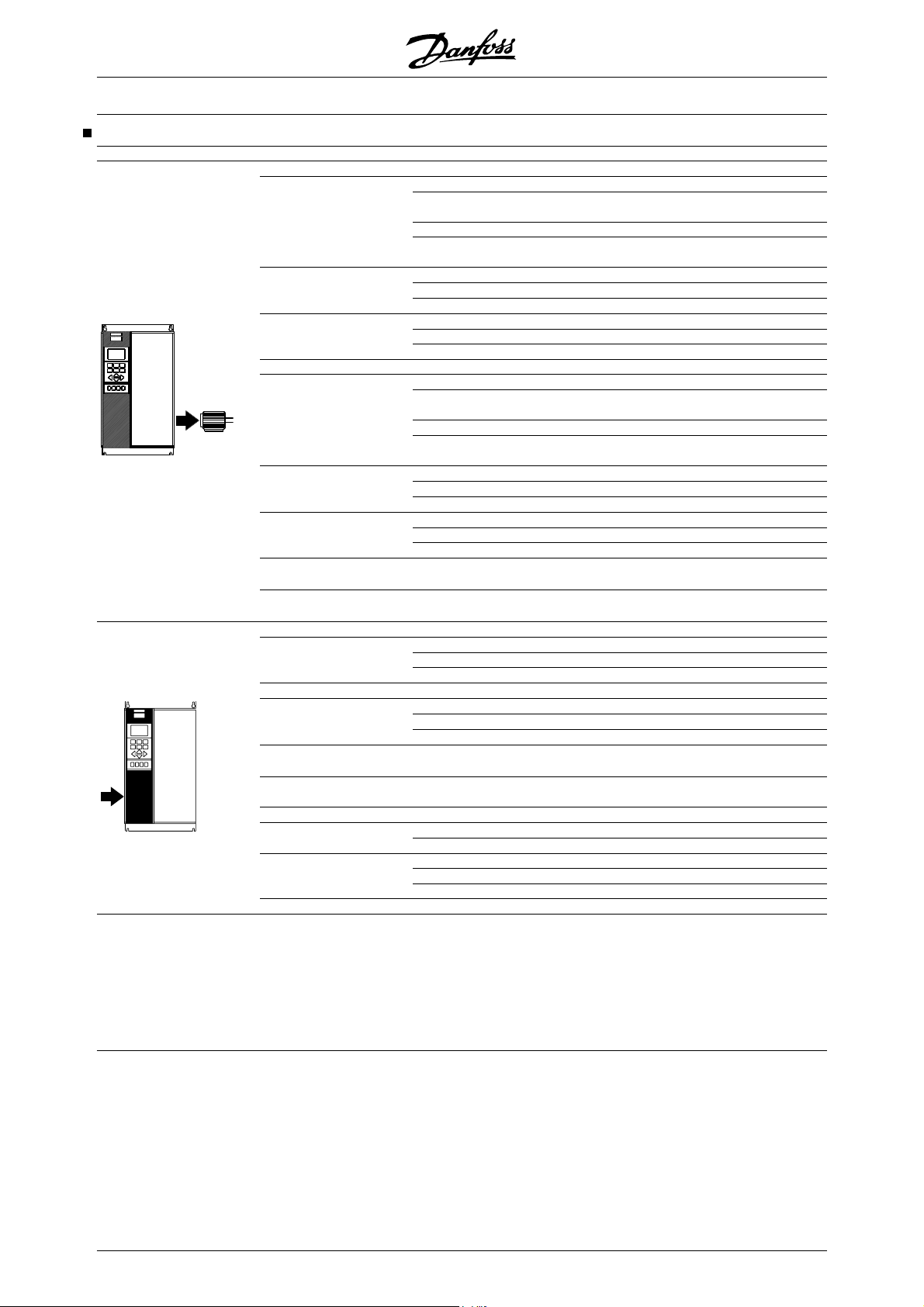
2. Electrical Installation, power
NOTE: The terminals are detachable on VLT 5001 - 5006, 200 - 240 V, VLT 5001 - 5011, 380 - 500 V and VLT
5001 - 5011, 525 - 600 V
Connect the mains supply to the mains terminals L1, L2, L3 of the frequency converter and to the earth connection
(fig. 5-8). Cable relief fitting is placed on the wall for Bookstyle units. Mount screened motor cable to the motor
terminals U, V, W, PE of the frequency converter. Make sure, the screen is connected electrically to the drive.
Fig. 5
Bookstyle IP 20
5001 - 5011 380 - 500 V
5001 - 5006 200 - 240 V
Fig. 6
Compact IP 20 and IP 54
5001 - 5011 380 - 500 V
5001 - 5006 200 - 240 V
5001 - 5011 525 - 600 V
Fig. 7
Compact IP 20
5016 - 5102 380 - 500 V
5008 - 5027 200 - 240 V
5016 - 5062 525 - 600 V
Compact IP 54
5016 - 5062 380 - 500 V
5008 - 5027 200 - 240 V
Quick Setup
Fig. 8
Fig. 9
Compact IP 54
5072 - 5102 380 - 500 V
MG.52.A3.02 - VLT® is a registered Danfoss trademark 7
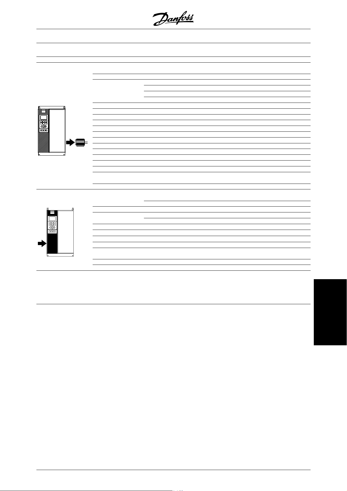
3. Electrical installation, control leads
Use a screw driver to remove the front cover under the
control panel.
NOTE: The terminals are detachable. Connect a jumber between terminals 12 and 27 (Fig. 10)
Mount screened cable to external start/stop of control
terminals 12 and 18.
VLT® 5000 Series
Fig. 10
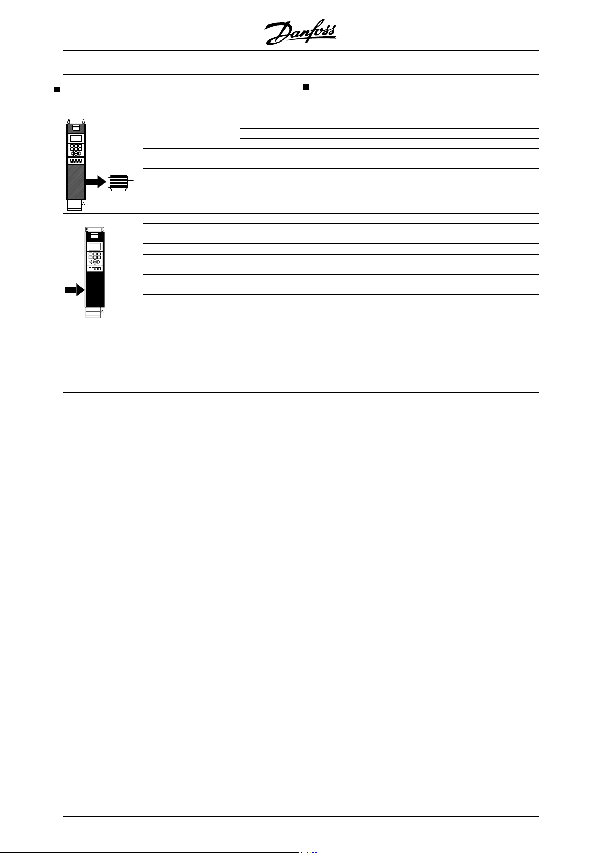
4. Programming
The frequency converter is programmed over the control panel.
Press the QUICK MENU button. The Quick Menu appears in the display. You choose parameters by
means of arrow up and arrow down. Press the
CHANGE DATA button to change parameter value.
Data values are changed using the up and down arrows. Press the left or right buttons to move the cursor.
Press OK to save your parameter setting.
Set the desired language in parameter 001. You have
six possibilities: English, German, French, Danish,
Spanish and Italian.
Set the motor parameters according to the motorplate:
Motor power
Motor voltage
Motor frequency
Motor current
Rated motor speed
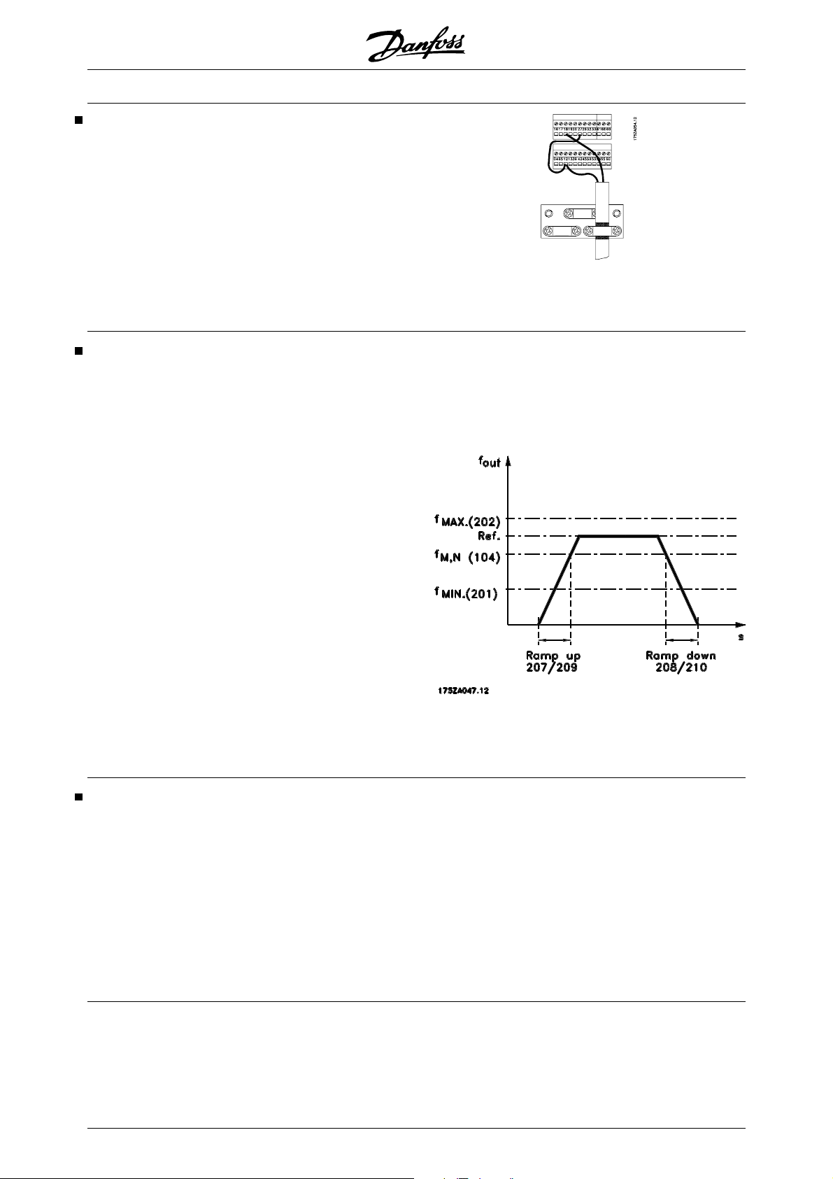
Set frequency interval and ramp times (Fig. 11)
Parameter 102
Parameter 103
Parameter 104
Parameter 105
Parameter 106
Min. reference
Max. reference
Ramp up time
Ramp down time
Set Operation site, Parameter 002 for Local.
Parameter 204
Parameter 205
Parameter 207
Parameter 208
Fig. 11
5. Motor Start
Press the START button to start the motor. Set motor
speed in Parameter 003. Check if the direction of rotations is as shown in the display. It can be changed by
swapping two phases of the motor cable.
Press the STOP button to stop the motor.
Select total or reduced Automatic Motor Adaption
(AMA) in Parameter 107. For further description of
AMA, see section Automatic Motor Adaption, AMA.
8 MG.52.A3.02 - VLT® is a registered Danfoss trademark
Press the START button to start the Automatic Motor
Adaption (AMA).
Press the DISPLAY/STATUS button to leave the
Quick Menu.
VLT® 5000 Series
Available literature
Supplied with the unit:
Operating instructions MG.51.AX.YY
High Power Installation Guide MI.90.JX.YY
Communication with VLT 5000:
VLT 5000 Profibus manual MG.10.EX.YY
VLT 5000 DeviceNet manual MG.50.HX.YY
VLT 5000 LonWorks manual MG.50.MX.YY
VLT 5000 Modbus manual MG.10.MX.YY
VLT 5000 Interbus manual MG.10.OX.YY
Application options for VLT 5000:
VLT 5000 SyncPos option manual MG.10.EX.YY
VLT 5000 Positioning controller manual MG.50.PX.YY
VLT 5000 Synchronising controller manual MG.10.NX.YY
Ring spinning option MI.50.ZX.02
Wobble function option MI.50.JX.02
Winder and Tension control option MG.50.KX.02
Instructions for VLT 5000:
Loadsharing MI.50.NX.02
VLT 5000 Brake resistors MI.90.FX.YY
Brake resistors for horizontal applications (VLT 5001 - 5011) (Only in English and German) MI.50.SX.YY
LC filter modules MI.56.DX.YY
Converter for encoder inputs (5V TTL to 24 V DC) (Only in combined English/German) MI.50.IX.51
Back Plate to VLT 5000 Series MN.50.XX.02
Below is a list of the literature available for VLT 5000.
It must be noted that there may be deviations from one
country to another.
Introduction
Various literature for VLT 5000:
Design Guide MG.51.BX.YY
Incorporating a VLT 5000 Profibus in a Simatic S5 SYSTEM MC.50.CX.02
Incorporating a VLT 5000 Profibus in a Simatic S7 SYSTEM MC.50.AX.02
Hoist and the VLT 5000 series MN.50.RX.02
Miscellaneous (only in English):
Protection against electrical hazards MN.90.GX.02
Choice of prefuses MN.50.OX.02
VLT on IT mains MN.90.CX.02
Filtering of harmonic currents MN.90.FX.02
Handling aggressive environments MN.90.IX.02
CI-TITM contactors - VLT® frequency converters MN.90.KX.02
VLT® frequency converters and UniOP operator panels MN.90.HX.02
X = version number
YY = language version
MG.52.A3.02 - VLT® is a registered Danfoss trademark 9

VLT® 5000 Series
General technical data
Mains supply (L1, L2, L3):
Supply voltage 200-240 V units 3 x 200/208/220/230/240 V ±10%
Supply voltage 380-500 V units 3 x 380/400/415/440/460/500 V ±10%
Supply voltage 525-600 V units 3 x 525/550/575/600 V ±10%
Supply voltage 525-690 V units 3 x 525/550/575/600/690 V ±10%
Supply frequency 48-62 Hz +/- 1 %
See the section on special conditions in the Design Guide
Max imbalance of supply voltage:
VLT 5001-5011, 380-500 V and 525-600 V and VLT 5001-5006, 200-240 V ±2.0% of rated supply voltage
VLT 5016-5062, 380-500 V and 525-600 V and VLT 5008-5027, 200-240 V ±1.5% of rated supply voltage
VLT 5072-5552, 380-500 V and VLT 5032-5052, 200-240 V ±3.0% of rated supply voltage
VLT 5042-5602, 525-690 V ±3.0% of rated supply voltage
True Power factor (λ)
Displacement Power Factor (cos φ)
No. of switchings on supply input L1, L2, L3 approx. 1 time/min.
See the section on special conditions in the Design Guide
VLT output data (U, V, W):
Output voltage 0-100% of supply voltage
Output frequency VLT 5001-5027, 200-240 V 0-132 Hz, 0-1000 Hz
Output frequency VLT 5032-5052, 200-240 V 0-132 Hz, 0-450 Hz
Output frequency VLT 5001-5052, 380-500 V 0-132 Hz, 0-1000 Hz
Output frequency VLT 5062-5302, 380-500 V 0-132 Hz, 0-450 Hz
Output frequency VLT 5352-5552, 380-500 V 0-132 Hz, 0-300 Hz
Output frequency VLT 5001-5011, 525-600 V 0-132 Hz, 0-700 Hz
Output frequency VLT 5016-5052, 525-600 V 0-132 Hz, 0-1000 Hz
Output frequency VLT 5062, 525-600 V 0-132 Hz, 0-450 Hz
Output frequency VLT 5042-5302, 525-690 V 0-132 Hz, 0-200 Hz
Output frequency VLT 5352-5602, 525-690 V 0-132 Hz, 0-150 Hz
Rated motor voltage, 200-240 V units 200/208/220/230/240 V
Rated motor voltage, 380-500 V units 380/400/415/440/460/480/500 V
Rated motor voltage, 525-600 V units 525/550/575 V
Rated motor voltage, 525-690 V units 525/550/575/690 V
Rated motor frequency 50/60 Hz
Switching on output Unlimited
Ramp times 0.05-3600 sec.
0.90 nominal at rated load
near unity (>0.98)
Torque characteristics:
Starting torque, VLT 5001-5027, 200-240 V and VLT 5001-5552, 380-500 V 160% for 1 min.
Starting torque, VLT 5032-5052, 200-240 V 150% for 1 min.
Starting torque, VLT 5001-5062, 525-600 V 160% for 1 min.
Starting torque, VLT 5042-5602, 525-690 V 160% for 1 min.
Starting torque 180% for 0.5 sec.
Acceleration torque 100%
Overload torque, VLT 5001-5027, 200-240 V and VLT 5001-5552, 380-500 V,
VLT 5001-5062, 525-600 V, and VLT 5042-5602, 525-690 V
Overload torque, VLT 5032-5052, 200-240 V 150%
Arresting torque at 0 rpm (closed loop) 100%
The torque characteristics given are for the frequency converter at the high overload torque level (160%). At the
normal overload torque (110%), the values are lower.
10 MG.52.A3.02 - VLT® is a registered Danfoss trademark
160%

VLT® 5000 Series
Braking at high overload torque level
200-240 V
5001-5027
5032-5052
380-500 V
5001-5102
5122-5252
5302
5352-5552
525-600 V
5001-5062
525-690 V
5042-5352
5402-5602
1) VLT 5502 at 90% torque. At 100% torque the braking duty cycle is 13%. At mains rating 441-500 V 100% torque the braking duty
cycle is 17%.
VLT 5552 at 80% torque. At 100% torque the braking duty cycle is 8%.
2) Based on 300 second cycle:
For VLT 5502 the torque is 145%.
For VLT 5552 the torque is 130%.
3) VLT 5502 at 80% torque.
VLT 5602 at 71% torque.
4) Based on 300 second cycle.
For VLT 5502 the torque is 128%.
For VLT 5602 the torque is 114%.
Cycle time (s) Braking duty cycle at 100% torque Braking duty cycle at over torque
120 Continuous 40%
300 10% 10%
120 Continuous 40%
600 Continuous 10%
600 40% 10%
600
120 Continuous 40%
600 40% 10%
600
40%
40%
1)
3)
(150/160%)
2)
10%
4)
10%
Control card, digital inputs:
Number of programmable digital inputs 8
Terminal nos. 16, 17, 18, 19, 27, 29, 32, 33
Voltage level 0-24 V DC (PNP positive logics)
Voltage level, logical '0' < 5 V DC
Voltage level, logical '1' >10 V DC
Maximum voltage on input 28 V DC
Input resistance, R
i
2 kΩ
Scanning time per input 3 msec.
Reliable galvanic isolation: All digital inputs are galvanically isolated from the supply voltage (PELV). In addition, the
digital inputs can be isolated from the other terminals on the control card by connecting an external 24 V DC supply
and opening switch 4. VLT 5001-5062, 525-600 V do not meet PELV.
Control card, analogue inputs:
No. of programmable analogue voltage inputs/thermistor inputs 2
Terminal nos. 53, 54
Voltage level 0 - ±10 V DC (scalable)
Input resistance, R
i
10 kΩ
No. of programmable analogue current inputs 1
Terminal no. 60
Current range 0/4 - ±20 mA (scalable)
Input resistance, R
i
200 Ω
Resolution 10 bit + sign
Accuracy on input Max. error 1% of full scale
Scanning time per input 3 msec.
Terminal no. ground 55
Technical data
Reliable galvanic isolation: All analogue inputs are galvanically isolated from the supply voltage (PELV)* as well as
other inputs and outputs.
* VLT 5001-5062, 525-600 V do not meet PELV.
MG.52.A3.02 - VLT® is a registered Danfoss trademark 11

VLT® 5000 Series
Control card, pulse/encoder input:
No. of programmable pulse/encoder inputs 4
Terminal nos. 17, 29, 32, 33
Max. frequency on terminal 17 5 kHz
Max. frequency on terminals 29, 32, 33 20 kHz (PNP open collector)
Max. frequency on terminals 29, 32, 33 65 kHz (Push-pull)
Voltage level 0-24 V DC (PNP positive logics)
Voltage level, logical '0' < 5 V DC
Voltage level, logical '1' >10 V DC
Maximum voltage on input 28 V DC
Input resistance, R
i
Scanning time per input 3 msec.
Resolution 10 bit + sign
Accuracy (100-1 kHz), terminals 17, 29, 33 Max. error: 0.5% of full scale
Accuracy (1-5 kHz), terminal 17 Max. error: 0.1% of full scale
Accuracy (1-65 kHz), terminals 29, 33 Max. error: 0.1% of full scale
Reliable galvanic isolation: All pulse/encoder inputs are galvanically isolated from the supply voltage (PELV)*. In addition, pulse and encoder inputs can be isolated from the other terminals on the control card by connecting an
external 24 V DC supply and opening switch 4.
* VLT 5001-5062, 525-600 V do not meet PELV.
2 kΩ
Control card, digital/pulse and analogue outputs:
No. of programmable digital and analogue outputs 2
Terminal nos. 42, 45
Voltage level at digital/pulse output 0 - 24 V DC
Minimum load to ground (terminal 39) at digital/pulse output
600 Ω
Frequency ranges (digital output used as pulse output) 0-32 kHz
Current range at analogue output 0/4 - 20 mA
Maximum load to ground (terminal 39) at analogue output
500 Ω
Accuracy of analogue output Max. error: 1.5% of full scale
Resolution on analogue output. 8 bit
Reliable galvanic isolation: All digital and analogue outputs are galvanically isolated from the supply voltage (PELV)*,
as well as other inputs and outputs.
* VLT 5001-5062, 525-600 V do not meet PELV.
Control card, 24 V DC supply:
Terminal nos. 12, 13
Max. load (short-circuit protection) 200 mA
Terminal nos. ground 20, 39
Reliable galvanic isolation: The 24 V DC supply is galvanically isolated from the supply voltage (PELV)*, but has the
same potential as the analogue outputs.
* VLT 5001-5062, 525-600 V do not meet PELV.
Control card, RS 485 serial communication:
Terminal nos. 68 (TX+, RX+), 69 (TX-, RX-)
Reliable galvanic isolation: Full galvanic isolation.
Relay outputs:
1)
No. of programmable relay outputs 2
Terminal nos., control card (resistive load only) 4-5 (make)
12 MG.52.A3.02 - VLT® is a registered Danfoss trademark

VLT® 5000 Series
Max. terminal load (AC1) on 4-5, control card 50 V AC, 1 A, 50 VA
Max. terminal load (DC1 (IEC 947)) on 4-5, control card 25 V DC, 2 A / 50 V DC, 1 A, 50 W
Max. terminal load (DC1) on 4-5, control card for UL/cUL applications 30 V AC, 1 A / 42.5 V DC, 1A
Terminal nos., power card (resistive and inductive load) 1-3 (break), 1-2 (make)
Max. terminal load (AC1) on 1-3, 1-2, power card 250 V AC, 2 A, 500 VA
Max. terminal load (DC1 (IEC 947)) on 1-3, 1-2, power card 25 V DC, 2 A / 50 V DC, 1A, 50 W
Min. terminal load (AC/DC) on 1-3, 1-2, power card 24 V DC, 10 mA / 24 V AC, 100 mA
1) Rated values for up to 300,000 operations.
At inductive loads the number of operations are reduced by 50%, alternatively the current can be reduced by
50%, thus the 300,000 operations are maintained.
Brake resistor terminals (only SB, EB, DE and PB units):
Terminal nos. 81, 82
External 24 Volt DC supply:
Terminal nos. 35, 36
Voltage range 24 V DC ±15% (max. 37 V DC for 10 sec.)
Max. voltage ripple 2 V DC
Power consumption 15 W - 50 W (50 W for start-up, 20 msec.)
Min. pre-fuse 6 Amp
Reliable galvanic isolation: Full galvanic isolation if the external 24 V DC supply is also of the PELV type.
Cable lengths, cross-sections and connectors:
Max. motor cable length, screened cable 150 m
Max. motor cable length, unscreened cable 300 m
Max. motor cable length, screened cable VLT 5011 380-500 V 100 m
Max. motor cable length, screened cable VLT 5011 525-600 V
and VLT 5008, normal overload mode, 525-600 V
Max. brake cable length, screened cable 20 m
Max. loadsharing cable length, screened cable 25 m from frequency converter to DC bar.
Max. cable cross-section for motor, brake and loadsharing, see Electrical data
Max. cable cross-section for 24 V external DC supply
- VLT 5001-5027 200-240 V; VLT 5001-5102 380-500 V; VLT 5001-5062 525-600 V
- VLT 5032-5052 200-240 V; VLT 5122-5552 380-500 V; VLT 5042-5602 525-690 V 2.5 mm2 /12 AWG
Max. cross-section for control cables 1.5 mm 2 /16 AWG
Max. cross-section for serial communication 1.5 mm2 /16 AWG
If UL/cUL is to be complied with, copper cable with temperature class 60/75°C must be used
(VLT 5001 - 5062 380 - 500 V, 525 - 600 V and VLT 5001 - 5027 200 - 240 V).
If UL/cUL is to be complied with, copper cable with temperature class 75°C must be used
(VLT 5072 - 5552 380 - 500 V, VLT 5032 - 5052 200 - 240 V, VLT 5042 - 5602 525 - 690 V).
Connectors are for use of both copper and aluminium cables, unless other is specified.
4 mm2 /10 AWG
50 m
Technical data
Accuracy of display readout (parameters 009-012):
Motor current [6] 0-140% load Max. error: ±2.0% of rated output current
Torque % [7], -100 - 140% load Max. error: ±5% of rated motor size
Output [8], power HP [9], 0-90% load Max. error: ±5% of rated output
Control characteristics:
Frequency range 0 - 1000 Hz
Resolution on output frequency ±0.003 Hz
MG.52.A3.02 - VLT® is a registered Danfoss trademark 13

VLT® 5000 Series
System response time 3 msec.
Speed, control range (open loop) 1:100 of synchro. speed
Speed, control range (closed loop) 1:1000 of synchro. speed
Speed, accuracy (open loop) < 1500 rpm: max. error ± 7.5 rpm
Speed, accuracy (closed loop) < 1500 rpm: max. error ± 1.5 rpm
Torque control accuracy (open loop) 0- 150 rpm: max. error ±20% of rated torque
Torque control accuracy (speed feedback) Max. error ±5% of rated torque
All control characteristics are based on a 4-pole asynchronous motor
Externals:
Enclosure (dependent on power size) IP 00, IP 20, IP 21, Nema 1, IP 54
Vibration test 0.7 g RMS 18-1000 Hz random. 3 directions for 2 hours (IEC 68-2-34/35/36)
Max. relative humidity 93 % (IEC 68-2-3) for storage/transport
Max. relative humidity 95 % non condensing (IEC 721-3-3; class 3K3) for operation
Aggressive environment (IEC 721 - 3 - 3) Uncoated class 3C2
Aggressive environment (IEC 721 - 3 - 3) Coated class 3C3
Ambient temperature IP 20/Nema 1 (high overload torque 160%) Max. 45°C (24-hour average max. 40°C)
Ambient temperature IP 20/Nema 1 (normal overload torque 110%) Max. 40°C (24-hour average max. 35°C)
Ambient temperature IP 54 (high overload torque 160%) Max. 40°C (24-hour average max. 35°C)
Ambient temperature IP 54 (normal overload torque 110%) Max. 40°C (24-hour average max. 35°C)
Ambient temperature IP 20/54 VLT 5011 500 V Max. 40°C (24-hour average max. 35°C)
Ambient temperature IP 54 VLT 5042-5602, 525-690 V; and
5122-5552, 380-500 V (high overload torque 160%)
Max. 45°C (24-hour average max. 40°C)
Derating for high ambient temperature, see the Design Guide
Min. ambient temperature in full operation
Min. ambient temperature at reduced performance -10°C
Temperature during storage/transport -25 - +65/70°C
Max. altitude above sea level 1000 m
Derating for altitude over 1000 m above sealevel, see the Design Guide
EMC standards applied, Emission
EMC standards applied, Immunity
See section on special conditions in the Design Guide
VLT 5001-5062, 525 - 600 V do not comply with EMC or Low Voltage Directives.
IP54 units are not intended for direct outdoor installation. The IP54 rating does not relate to other exposures as sun,
icing, wind blown driving rain. Under such circumstances Danfoss recommends to install the units in an enclosure
designed for these environmental conditions. Alternatively, an installation at minimum 0.5 m above surface and
covered by a shed is recommended
EN 61000-6-3, EN 61000-6-4, EN 61800-3, EN 55011
EN 61000-6-2, EN 61000-4-2, EN 61000-4-3, EN 61000-4-4
EN 61000-4-5, EN 61000-4-6, VDE 0160/1990.12
0°C
14 MG.52.A3.02 - VLT® is a registered Danfoss trademark

VLT® 5000 Series
VLT 5000 Series protection:
Electronic motor thermal protection against overload.
Temperature monitoring of heat-sink ensures that the frequency converter cuts out if the temperature reaches 90°
C for IP 00, IP 20 and Nema 1. For IP 54, the cut-out temperature is 80°C. An overtemperature can only be reset
when the temperature of the heat-sink has fallen below 60°C.
For the units mentioned below, the limits are as follows:
- VLT 5122, 380-500 V, cuts out at 75°C and can be reset if the temperature has fallen below 60°C.
- VLT 5152, 380-500 V, cuts out at 80°C and can be reset if the temperature has fallen below 60°C.
- VLT 5202, 380-500 V, cuts out at 95°C and can be reset if the temperature has fallen below 65°C.
- VLT 5252, 380-500 V, cuts out at 95°C and can be reset if the temperature has fallen below 65°C.
- VLT 5302, 380-500 V, cuts out at 105°C and can be reset if the temperature has fallen below 75°C.
- VLT 5352-5552, 380-500 V, cut out at 85°C and can be reset if the temperature has fallen below 60°C.
- VLT 5042-5122, 525-690 V, cut out at 75°C and can be reset if the temperature has fallen below 60°C.
- VLT 5152, 525-690 V, cuts out at 80°C and can be reset if the temperature has fallen below 60°C.
- VLT 5202-5352, 525-690 V, cut out at 100°C and can be reset if the temperature has fallen below 70°C.
- VLT 5402-5602, 525-690 V, cut out at 75°C and can be reset if the temperature has fallen below 60°C.
The frequency converter is protected against short-circuiting on motor terminals U, V, W.
The frequency converter is protected against earth fault on motor terminals U, V, W.
Monitoring of the intermediate circuit voltage ensures that the frequency converter cuts out if the intermediate circuit voltage becomes
too high or too low.
If a motor phase is missing, the frequency converter cuts out, see parameter 234 Motor phase monitor.
If there is a mains fault, the frequency converter is able to carry out a controlled decelleration.
If a mains phase is missing, the frequency converter will cut out when a load is placed on the motor.
MG.52.A3.02 - VLT® is a registered Danfoss trademark 15
Technical data
VLT® 5000 Series
Electrical data
Bookstyle and Compact, Mains supply 3 x 200 240 V
According to international requirements VLT type 5001 5002 5003 5004 5005 5006
Output current
I
VLT, MAX
Output (240 V) S
Typical shaft output
Typical shaft output
Max. cable cross-section to motor,
brake and loadsharing [mm
2
]/[AWG]2 )
Rated input current
Max. cable
cross-section power [mm
2
]/[AWG] 2 )
Max. pre-fuses
Efficiency
3)
Weight IP 20 EB Bookstyle [kg] 7 7 7 9 9 9.5
Weight IP 20 EB Compact [kg] 8 8 8 10 10 10
Weight IP 54 Compact [kg] 11.5 11.5 11.5 13.5 13.5 13.5
Power loss at
max. load.
Enclosure
1. For type of fuse see section Fuses.
2. American Wire Gauge.
3. Measured using 30 m screened motor cables at rated load and rated frequency.
I
(60 s) [A]
VLT,N
P
VLT,N
P
VLT,N
(200 V)I
[-]/UL1) [A]
[A]
VLT,N
3.7 5.4 7.8 10.6 12.5 15.2
5.9 8.6 12.5 17 20 24.3
[kVA]
1.5 2.2 3.2 4.4 5.2 6.3
[kW]
0.75 1.1 1.5 2.2 3.0 3.7
[HP]
1 1.5 2 3 4 5
4/10
[A]
3.4 4.8 7.1 9.5 11.5 14.5
L,N
4/10
4/10 4/10 4/10 4/10 4/10
4/10 4/10 4/10 4/10 4/10
16/10 16/10 16/15 25/20 25/25 35/30
0.95 0.95 0.95 0.95 0.95 0.95
[W] 58 76 95 126 172 194
IP 20/
IP54
IP 20/
IP54
IP 20/
IP54
IP 20/
IP54
IP 20/
IP54
IP 20/
IP54
16 MG.52.A3.02 - VLT® is a registered Danfoss trademark
VLT® 5000 Series
Compact, Mains supply 3 x 200 - 240 V
According to international requirements VLT type 5008 5011 5016 5022 5027
Normal overload torque (110 %):
I
[A]
Output current
I
VLT, MAX
Output (240 V) S
Typical shaft output
Typical shaft output
VLT,N
P
VLT,N
P
VLT,N
VLT,N
32 46 61.2 73 88
(60 s)
35.2 50.6 67.3 80.3 96.8
[A]
[kVA]
13.3 19.1 25.4 30.3 36.6
[kW]
7.5 11 15 18.5 22
[HP]
10 15 20 25 30
High overload torque (160 %):
I
[A]
Output current
Output (240 V) S
Typical shaft output
Typical shaft output
Max. cable cross-section to motor, IP 54 16/6 16/6 35/2 35/2 50/0
brake and loadsharing [mm
Min. cable cross-section to motor, brake and
loadsharing
4)
[mm2 /AWG]
2
2)
I
VLT, MAX
VLT,N
P
VLT,N
P
VLT,N
/AWG]2)
VLT,N
25 32 46 61.2 73
(60 s)
40 51.2 73.6 97.9 116.8
[A]
[kVA]
10 13 19 25 30
[kW]
5.5 7.5 11 15 18.5
[HP]
7.5 10 15 20 25
5)
IP 20 16/6 35/2 35/2 35/2 50/0
10/8 10/8 10/8 10/8 16/6
Rated input current
Max. cable cross-section, IP 54 16/6 16/6 35/2 35/2 50/0
power [mm
2
]/[AWG]2)
(200 V) I
5)
Max. pre-fuses
Efficiency
3)
[A]
L,N
[-]/UL1) [A]
32 46 61 73 88
IP 20 16/6 35/2 35/2 35/2 50/0
50 60 80 125 125
0.95 0.95 0.95 0.95 0.95
Weight IP 20 EB [kg] 21 25 27 34 36
Weight IP 54 [kg] 38 40 53 55 56
Power loss at max. load.
- high overload torque
(160 %)
- normal overload torque
(110 %)
Enclosure
[W]
[W]
340 426 626 833 994
426 545 783 1042 1243
IP 20/
IP 54
IP 20/
IP 54
IP 20/
IP 54
IP 20/
IP 54
IP 20/
IP 54
1. For type of fuse see section Fuses
2. American Wire Gauge.
3. Measured using 30 m screened motor cables at rated load and rated frequency.
4. Min. cable cross-section is the smallest cable cross-section allowed to be fitted on the terminals to comply with IP 20. Always comply
with national and local regulations on min. cable cross-section.
5. Aluminium cables with cross-section above 35 mm
2
must be connected by use of a AI-Cu connector.
Technical data
MG.52.A3.02 - VLT® is a registered Danfoss trademark 17
VLT® 5000 Series
Compact, Mains supply 3 x 200 - 240 V
According to international requirements VLT type 5032 5042 5052
Normal overload torque (110 %):
Output current
I
Output
S
(60 s) [A] (200-230 V)
I
VLT, MAX
[A] (231-240 V)
I
VLT,N
(60 s) [A] (231-240 V)
VLT, MAX
[kVA] (208 V)
S
VLT,N
[kVA] (230 V)
S
VLT,N
[kVA] (240 V)
VLT,N
[A] (200-230 V)
VLT,N
115 143 170
127 158 187
104 130 154
115 143 170
41 52 61
46 57 68
43 54 64
I
Typical shaft output [HP] (208 V) 40 50 60
Typical shaft output [kW] (230 V) 30 37 45
High overload torque (160 %):
Output current
I
Output
S
I
[A] (200-230 V)
VLT,N
[A] (200-230 V)
I
VLT, MAX
[A] (231-240 V)
I
VLT,N
[A] (231-240 V)
VLT, MAX
[kVA] (208 V)
S
VLT,N
S
[kVA] (230 V)
VLT,N
[kVA] (240 V)
VLT,N
88 115 143
132 173 215
80 104 130
120 285 195
32 41 52
35 46 57
33 43 54
Typical shaft output [HP] (208 V) 30 40 50
[kW] (230 V) 22 30 37
Max. cable cross-section to motor
and loadsharing
Max. cable cross-section to brake
Normal overload torque (110 %):
Rated input current
Normal overload torque (150 %):
Rated input current
Max. cable cross-section
power supply
Min. cable cross-section to motor,
power
[mm2 ]
[AWG]
[mm2 ]
[AWG]
I
[A] (230 V)
L,N
4,6
[mm2]
[AWG]
4,6
[mm2]
[AWG]
4,6
2,4,6
4,6
2,4,6
2,4,6
2,4,6
I
[A] (230 V)
L,N
120
300 mcm
25
4
101.3 126.6 149.9
77,9 101,3 126,6
120
300 mcm
6
8
supply, brake and loadsharing
Max. pre-fuses (mains) [-]/UL
Efficiency
3
Power loss
1
[A]
Normal overload [W]
150/15
200/200 250/250
0
0,96-0,97
1089 1361 1612
High overload [W] 838 1089 1361
Weight
Weight
Weight
IP 00 [kg]
IP 20 Nema1 [kg]
IP 54 Nema12 [kg] 104 104 104
101 101 101
101 101 101
Enclosure IP 00 / Nema 1 (IP 20) / IP 54
1. For type of fuse see section Fuses
2. American Wire Gauge.
3. Measured using 30 m screened motor cables at rated load and rated frequency.
4. Max. cable cross-section is the maximum possible cable cross-section allowed to be fitted on the terminals. Min. cable cross-section
is the minimum allowed cross-section. Always comply with national and local regulations on min. cable cross-section.
5. Weight without shipping container.
6. Connection stud: M8 Brake: M6.
18 MG.52.A3.02 - VLT® is a registered Danfoss trademark
VLT® 5000 Series
Bookstyle and Compact, Mains supply 3 x 380 500 V
According to international requirements VLT type 5001 5002 5003 5004
Output current
I
I
Output
S
Typical shaft output
Typical shaft output
Max. cable cross-section to motor,
brake and loadsharing [mm
2
]/[AWG]2 )
Rated input current
Max. cable cross-section, power [mm2 ]/[AWG]
Max. pre-fuses [-]/UL1) [A]
Efficiency
3)
Weight IP 20 EB Bookstyle [kg] 7 7 7 7.5
Weight IP 20 EB Compact [kg] 8 8 8 8.5
Weight IP 54 Compact [kg] 11.5 11.5 11.5 12
Power loss at max. load [W] 55 67 92 110
Enclosure
I
VLT,N
(60 s) [A] (380-440 V)
VLT, MAX
I
VLT,N
(60 s) [A] (441-500 V)
VLT, MAX
[kVA] (380-440 V)
S
VLT,N
[kVA] (441-500 V)
VLT,N
2)
[A] (380-440 V)
[A] (441-500 V)
P
[kW]
VLT,N
P
[HP]
VLT,N
[A] (380 V)
I
L,N
I
[A] (460 V)
L,N
2.2 2.8 4.1 5.6
3.5 4.5 6.5 9
1.9 2.6 3.4 4.8
3 4.2 5.5 7.7
1.7 2.1 3.1 4.3
1.6 2.3 2.9 4.2
0.75 1.1 1.5 2.2
1 1.5 2 3
4/10
4/10 4/10 4/10
2.3 2.6 3.8 5.3
1.9 2.5 3.4 4.8
4/10 4/10 4/10 4/10
16/6 16/6 16/10 16/10
0.96 0.96 0.96 0.96
IP 20/
IP 54
IP 20/
IP 54
IP 20/
IP 54
IP 20/
IP 54
1. For type of fuse see section Fuses.
2. American Wire Gauge.
3. Measured using 30 m screened motor cables at rated load and rated frequency.
Technical data
MG.52.A3.02 - VLT® is a registered Danfoss trademark 19
VLT® 5000 Series
Bookstyle and Compact, Mains supply 3 x 380 - 500
V
According to international requirements VLT type 5005 5006 5008 5011
Output current
I
I
Output
S
Typical shaft output
Typical shaft output
Max. cable cross-section to motor,
brake and loadsharing [mm
2
]/[AWG]2 )
Rated input current
I
Max. cable cross-section power [mm2 ]/[AWG]
Max. pre-fuses [-]/UL1) [A]
Efficiency
3)
Weight IP 20 EB Bookstyle [kg] 7.5 9.5 9.5 9.5
Weight IP 20 EB Compact [kg] 8.5 10.5 10.5 10.5
Weight IP 54 EB Compact [kg] 12 14 14 14
Power loss at max. load. [W] 139 198 250 295
Enclosure
I
VLT,N
(60 s) [A] (380-440 V)
VLT, MAX
I
VLT,N
(60 s) [A] (441-500 V)
VLT, MAX
[kVA] (380-440 V)
S
VLT,N
[kVA] (441-500 V)
VLT,N
[A] (380-440 V)
[A] (441-500 V)
P
[kW]
VLT,N
P
[HP]
VLT,N
[A] (380 V)
I
L,N
[A] (460 V)
L,N
2)
7.2 10 13 16
11.5 16 20.8 25.6
6.3 8.2 11 14.5
10.1 13.1 17.6 23.2
5.5 7.6 9.9 12.2
5.5 7.1 9.5 12.6
3.0 4.0 5.5 7.5
4 5 7.5 10
4/10
4/10 4/10 4/10
7 9.1 12.2 15.0
6 8.3 10.6 14.0
4/10 4/10 4/10 4/10
16/15 25/20 25/25 35/30
0.96 0.96 0.96 0.96
IP 20/
IP 54
IP 20/
IP 54
IP 20/
IP 54
IP 20/
IP 54
1. For type of fuse see section Fuses.
2. American Wire Gauge.
3. Measured using 30 m screened motor cables at rated load and rated frequency.
20 MG.52.A3.02 - VLT® is a registered Danfoss trademark
VLT® 5000 Series
Compact, Mains supply 3 x 380 - 500 V
According to international requirements VLT type 5016 5022 5027
Normal overload torque (110 %):
Output current
Output
Typical shaft output
Typical shaft output
I
VLT, MAX
I
VLT, MAX
VLT,N
(60 s) [A] (380-440 V)
I
VLT,N
(60 s) [A] (441-500 V)
[kVA] (380-440 V)
S
VLT,N
S
[kVA] (441-500 V)
VLT,N
[A] (380-440 V)
[A] (441-500 V)
P
VLT,N
P
VLT,N
32 37.5 44
35.2 41.3 48.4
27.9 34 41.4
30.7 37.4 45.5
24.4 28.6 33.5
[kW]
15 18.5 22
[HP]
20 25 30
24.2 29.4 35.8
I
High overload torque (160 %):
I
Output current
I
VLT, MAX
I
VLT, MAX
Output
S
S
Typical shaft output
Typical shaft output
Max. cable cross-section to motor, IP 54 16/6 16/6 16/6
brake and loadsharing [mm
Min. cable cross-section to motor,
brake and loadsharing [mm2]/[AWG]
2
]/[AWG]
2)
2) 4)
Rated input current
Max. cable cross-section, IP 54 16/6 16/6 16/6
power [mm
2
]/[AWG]
Max. pre-fuses
Efficiency
3)
[A] (380-440 V)
VLT,N
(60 s) [A] (380-440 V)
I
[A] (441-500 V)
VLT,N
(60 s) [A] (441-500 V)
[kVA] (380-440 V)
VLT,N
[kVA] (441-500 V)
VLT,N
P
VLT,N
P
VLT,N
I
[A] (380 V)
L,N
I
[A] (460 V)
L,N
[-]/UL1) [A]
24 32 37.5
38.4 51.2 60
21.7 27.9 34
34.7 44.6 54.4
18.3 24.4 28.6
[kW]
11 15 18.5
[HP]
15 20 25
18.8 24.2 29.4
IP 20 16/6 16/6 35/2
10/8 10/8 10/8
32 37.5 44
27.6 34 41
IP 20
16/6 16/6 35/2
63/40 63/50 63/60
0.96 0.96 0.96
Weight IP 20 EB [kg] 21 22 27
Weight IP 54 [kg] 41 41 42
Power loss at max. load.
- high overload torque (160 %)
[W] 419 559 655
- normal overload torque (110 %) [W] 559 655 768
Enclosure
IP 20/
IP 54
IP 20/
IP 54
IP 20/
IP 54
1. For type of fuse see section Fuses.
2. American Wire Gauge.
3. Measured using 30 m screened motor cables at rated load and rated frequency.
4. Min. cable cross-section is the smallest cable cross-section allowed to be fitted on the terminals to comply with IP 20. Always comply
with national and local regulations on min. cable cross-section.
Technical data
MG.52.A3.02 - VLT® is a registered Danfoss trademark 21
VLT® 5000 Series
Compact, Mains supply 3 x 380 - 500 V
According to international requirements VLT type 5032 5042 5052
Normal overload torque (110 %):
Output current
Output
Typical shaft output
Typical shaft output
I
VLT, MAX
I
VLT, MAX
VLT,N
(60 s) [A] (380-440 V)
I
VLT,N
(60 s) [A] (441-500 V)
[kVA] (380-440 V)
S
VLT,N
S
[kVA] (441-500 V)
VLT,N
[A] (380-440 V)
[A] (441-500 V)
P
VLT,N
P
VLT,N
61 73 90
67.1 80.3 99
54 65 78
59.4 71.5 85.8
46.5 55.6 68.6
[kW]
30 37 45
[HP]
40 50 60
46.8 56.3 67.5
I
High overload torque (160 %):
I
Output current
I
VLT, MAX
I
VLT, MAX
Output
S
S
Typical shaft output
Typical shaft output
Max. cable cross-section to motor, IP 54 35/2 35/2 50/0
brake and loadsharing [mm
Min. cable cross-section to motor,
brake and loadsharing [mm
2
]/[AWG]2)
2
]/[AWG]2)
Rated input current
I
Max. cable cross-section IP 54 35/2 35/2 50/0
power[mm
2
]/[AWG]
2) 5)
Max. pre-fuses
Efficiency
3)
[A] (380-440 V)
VLT,N
(60 s) [A] (380-440 V)
I
[A] (441-500 V)
VLT,N
(60 s) [A] (441-500 V)
[kVA] (380-440 V)
VLT,N
[kVA] (441-500 V)
VLT,N
5)
4)
P
VLT,N
P
VLT,N
I
[A] (380 V)
L,N
[A] (460 V)
L,N
[-]/UL1) [A]
44 61 73
70.4 97.6 116.8
41.4 54 65
66.2 86 104
33.5 46.5 55.6
[kW]
22 30 37
[HP]
30 40 50
35.9 46.8 56.3
IP20 35/2 35/2 50/0
10/8 10/8 16/6
60 72 89
53 64 77
IP 20 35/2 35/2 50/0
80/80 100/100 125/125
0.96 0.96 0.96
Weight IP 20 EB [kg] 28 41 42
Weight IP 54 [kg] 54 56 56
Power loss at max. load.
- high overload torque (160 %)
[W] 768 1065 1275
- normal overload torque (110 %) [W] 1065 1275 1571
Enclosure
IP 20/
IP 54
IP 20/
IP 54
IP 20/
IP 54
1. For type of fuse see section Fuses.
2. American Wire Gauge.
3. Measured using 30 m screened motor cables at rated load and rated frequency.
4. Min. cable cross-section is the smallest cable cross-section allowed to be fitted on the terminals to comply with IP 20. Always comply
with national and local regulations on min. cable cross-section.
5. Aluminium cables with cross-section above 35 mm
2
must be connected by use of a AI-Cu connector.
22 MG.52.A3.02 - VLT® is a registered Danfoss trademark
VLT® 5000 Series
Compact, Mains supply 3 x 380 - 500 V
According to international requirements VLT type 5062 5072 5102
Normal overload torque (110 %):
Output current
Output
Typical shaft output
VLT,N
I
(60 s) [A] (380-440 V)
VLT, MAX
I
I
VLT, MAX
VLT,N
(60 s) [A] (441-500 V)
[kVA] (380-440 V)
S
VLT,N
S
[kVA] (441-500 V)
VLT,N
P
P
P
[A] (380-440 V)
[A] (441-500 V)
[kW] (400 V)
VLT,N
[HP] (460 V)
VLT,N
[kW] (500 V)
VLT,N
106 147 177
117 162 195
106 130 160
117 143 176
80.8 102 123
91.8 113 139
55 75 90
75 100 125
75 90 110
I
High overload torque (160 %):
I
Output current
I
VLT, MAX
I
VLT, MAX
Output
S
S
Typical shaft output
Max. cable cross-section to motor, IP 54
brake and loadsharing [mm2 ]/[AWG]
Min. cable cross-section to motor,
brake and loadsharing [mm
2
]/[AWG]
2)
4)
Rated input current
I
Max. cable cross-section IP 54
power[mm
2
]/[AWG]
2)
Max. pre-fuses
Efficiency
3)
[A] (380-440 V)
VLT,N
(60 s) [A] (380-440 V)
I
[A] (441-500 V)
VLT,N
(60 s) [A] (441-500 V)
[kVA] (380-440 V)
VLT,N
[kVA] (441-500 V)
VLT,N
P
[kW] (400 V)
VLT,N
[HP] (460 V)
P
VLT,N
P
[kW] (500 V)
VLT,N
I
[A] (380 V)
L,N
[A] (460 V)
L,N
[-]/UL1) [A]
90 106 147
135 159 221
80 106 130
120 159 195
68.6 73.0 102
69.3 92.0 113
45 55 75
60 75 100
55 75 90
IP20
50/0
50/0
5)
5)
150/300
mcm
120/250
mcm
6)
5)
150/300
mcm
120/250
mcm
16/6 25/4 25/4
104 145 174
104 128 158
IP 20
50/0
50/0
5)
5)
150/300
mcm
120/250
mcm
5)
150/300
mcm
120/250
mcm
160/150 225/225 250/250
>0.97 >0.97 >0.97
Weight IP 20 EB [kg] 43 54 54
Weight IP 54 [kg] 60 77 77
Power loss at max. load.
- high overload torque (160 %)
[W] 1122 1058 1467
- normal overload torque (110 %) [W] 1322 1467 1766
Enclosure
IP20/
IP 54
IP20/
IP 54
IP20/
IP 54
6)
5)
5)
1. For type of fuse see section Fuses.
2. American Wire Gauge.
3. Measured using 30 m screened motor cables at rated load and rated frequency.
4. Min. cable cross-section is the smallest cable cross-section allowed to be fitted on the terminals to comply with IP 20. Always comply
with national and local regulations on min. cable cross-section.
5. Aluminium cables with cross-section above 35 mm
used.
6. Brake and loadsharing: 95 mm
2
/ AWG 3/0
2
must be connected by use of a AI-Cu connector.
MG.52.A3.02 - VLT® is a registered Danfoss trademark 23
Technical data
VLT® 5000 Series
Compact, Mains supply 3 x 380 - 500 V
According to international requirements VLT type 5122 5152 5202 5252 5302
Normal overload current (110 %):
I
Output current
I
VLT, MAX
I
VLT, MAX
Output
S
Typical shaft output
[A] (380-440 V)
VLT,N
(60 s) [A] (380-440
[A] (441-500 V)
I
VLT,N
(60 s) [A] (441-500
[kVA] (400 V)
S
VLT,N
[kVA] (460 V)
S
VLT,N
[kVA] (500 V)
VLT,N
[kW] (400 V)
[HP] (460 V) 150 200 250 300 350
[kW] (500 V) 132 160 200 250 315
High overload torque (160 %):
I
Output current
I
VLT, MAX
I
VLT, MAX
Output
S
Typical shaft output
[A] (380-440 V)
VLT,N
(60 s) [A] (380-440
[A] (441-500 V)
I
VLT,N
(60 s) [A] (441-500
[kVA] (400 V)
S
VLT,N
[kVA] (460 V)
S
VLT,N
[kVA] (500 V)
VLT,N
[kW] (400 V)
[HP] (460 V) 125 150 200 250 300
Max. cable cross-section to
motor
Max. cable cross-section to
loadsharing and brake
[kW] (500 V) 110 132 160 200 250
[mm2]
[AWG]
[mm2]
[AWG]
Normal overload current (110 %):
I
Rated input current
I
[A] (380-440 V)
L,N
[A] (441-500 V)
L,N
High overload torque (160 %):
I
Rated input current
I
Max. cable cross-section
power supply
[A] (380-440 V)
L,N
[A] (441-500 V)
L,N
[mm2]
[AWG]
Max. pre-fuses (mains) [-]/
UL
Efficiency
Power loss
Weight
Weight
Weight
3
Normal overload [W]
High overload [W] 2206 2619 3309 4163 4977
IP 00 [kg]
IP 21/Nema1 [kg]
IP 54/Nema12 [kg] 96 104 125 136 151
Enclosure IP 00, IP 21/Nema 1 and IP 54/Nema12
212 260 315 395 480
233 286 347 434 528
V)
190 240 302 361 443
209 264 332 397 487
V)
147 180 218 274 333
151 191 241 288 353
165 208 262 313 384
110 132 160 200 250
177 212 260 315 395
266 318 390 473 593
V)
160 190 240 302 361
240 285 360 453 542
V)
123 147 180 218 274
127 151 191 241 288
139 165 208 262 313
90 110 132 160 200
4,6
2,4,6
4,6
2,4,6
2 x 70
2 x 2/0
2 x 70
2 x 2/0
2 x 185
2 x 350 mcm
2 x 185
2 x 350 mcm
208 256 317 385 467
185 236 304 356 431
174 206 256 318 389
158 185 236 304 356
4,6
2,4,6
[A]
2 x 70
2 x 2/0
300/
1
300
350/
350
450/
400
2 x 185
2 x 350 mcm
500/
500
0,98
2619 3309 4163 4977 6107
82 91 112 123 138
96 104 125 136 151
630/
600
1. For type of fuse see section Fuses
2. American Wire Gauge.
3. Measured using 30 m screened motor cables at rated load and rated frequency.
4. Max. cable cross-section is the maximum possible cable cross-section allowed to be fitted on the terminals. Always comply with
national and local regulations on min. cable cross-section.
5. Weight without shipping container.
6. Connection bolt power supply and motor: M10; Brake and loadsharing: M8
24 MG.52.A3.02 - VLT® is a registered Danfoss trademark

VLT® 5000 Series
Compact, Mains supply 3 x 380 - 500 V
According to international requirements VLT type 5352 5452 5502 5552
Normal overload current (110 %):
I
Output current
I
VLT, MAX
I
VLT, MAX
Output S
Typical shaft output
[A] (380-440 V)
VLT,N
(60 s) [A] (380-440
[A] (441-500 V)
I
VLT,N
(60 s) [A] (441-500
[kVA] (400 V)
VLT,N
[kVA] (460 V)
S
VLT,N
[kVA] (500 V)
S
VLT,N
[kW] (400 V) 315 355 400 450
[HP] (460 V)
[kW] (500 V) 355 400 500 530
High overload torque (160 %):
I
Output current
I
VLT, MAX
I
VLT, MAX
Output S
Typical shaft output
Max. cable cross-section
to motor and loadsharing
Max. cable cross-section
to brake
[A] (380-440 V)
VLT,N
(60 s) [A] (380-440
[A] (441-500 V)
I
VLT,N
(60 s) [A] (441-500
[kVA] (400 V)
VLT,N
[kVA] (460 V)
S
VLT,N
[kVA] (500 V)
S
VLT,N
[kW] (400 V) 250 315 355 400
[HP] (460 V)
[kW] (500 V) 315 355 400 500
[mm2]
[AWG]
[mm2]
[AWG]
Normal overload current (110 %):
I
Rated input current
I
[A] (380-440 V)
L,N
[A] (441-500 V)
L,N
High overload torque (160 %):
I
Rated input current
I
Max. cable cross-section
power supply
[A] (380-440 V)
L,N
[A] (441-500 V)
L,N
[mm2]
[AWG]
Max. pre-fuses (mains)
[-]/UL
Efficiency
Power loss
Weight
Weight
Weight
3
Normal overload [W]
High overload [W] 6005 6960 7691 7964
IP 00 [kg]
IP 21/Nema1 [kg]
IP 54/Nema12 [kg] 263 270 272 313
Enclosure IP 00, IP 21/Nema 1 and IP 54/Nema12
600 658 745 800
660 724 820 880
V)
540 590 678 730
594 649 746 803
V)
416 456 516 554
430 470 540 582
468 511 587 632
450 500 550/600 600
480 600 658 695
720 900 987 1042
V)
443 540 590 678
665 810 885 1017
V)
333 416 456 482
353 430 470 540
384 468 511 587
350 450 500 550
4,6
2,4,6
4,6
2,4,6
4x240
4x500 mcm
2x185
2x350 mcm
590 647 733 787
531 580 667 718
472 590 647 684
436 531 580 667
4,6
2,4,6
1
700/700 900/900 900/900 900/900
[A]
4x240
4x500 mcm
0,98
7630 7701 8879 9428
221 234 236 277
263 270 272 313
Technical data
1. For type of fuse see section Fuses
2. American Wire Gauge.
3. Measured using 30 m screened motor cables at rated load and rated frequency.
4. Max. cable cross-section is the maximum possible cable cross-section allowed to be fitted on the terminals. Always comply with
national and local regulations on min. cable cross-section.
5. Weight without shipping container.
6. Connection bolt power supply, motor and loadsharing: M10 (compression lug), 2xM8 (box lug), M8 (brake)
MG.52.A3.02 - VLT® is a registered Danfoss trademark 25
VLT® 5000 Series
Compact, Mains supply 3 x 525 - 600 V
According to international requirements VLT type 5001 5002 5003 5004
Normal overload torque (110 %):
I
Output current
I
VLT, MAX
I
VLT, MAX
Output S
Typical shaft output
Typical shaft output
Highl overload torque (160%):
Output current
I
VLT, MAX
I
VLT, MAX
Output
Typical shaft output
Typical shaft output
Max. cable cross-section to motor,
brake and loadsharing [mm
2
]/[AWG]
2)
S
S
S
[A] (550 V)
VLT,N
(60 s) [A] (550 V)
[A] (575 V)
I
VLT,N
(60 s) [A] (575 V)
[kVA] (550 V)
VLT,N
[kVA] (575 V)
VLT,N
P
[kW]
VLT,N
P
[HP]
VLT,N
I
[A] (550 V)
VLT,N
(60 s) [A] (550 V)
I
[A] (575 V)
VLT,N
(60 s) [A] (575 V)
[kVA] (550 V)
VLT,N
[kVA] (575 V)
VLT,N
P
[kW]
VLT,N
P
[HP]
VLT,N
2.6 2.9 4.1 5.2
2.9 3.2 4.5 5.7
2.4 2.7 3.9 4.9
2.6 3.0 4.3 5.4
2.5 2.8 3.9 5.0
2.4 2.7 3.9 4.9
1.1 1.5 2.2 3
1.5 2 3 4
1.8 2.6 2.9 4.1
2.9 4.2 4.6 6.6
1.7 2.4 2.7 3.9
2.7 3.8 4.3 6.2
1.7 2.5 2.8 3.9
1.7 2.4 2.7 3.9
0.75 1.1 1.5 2.2
1 1.5 2 3
4/10 4/10 4/10 4/10
Normal overload torque (110 %):
Rated input current
[A] (550 V)
I
L,N
I
[A] (600 V)
L,N
High overload torque ( 160 %):
I
Rated input current
I
Max. cable cross-section, power [mm2 ]/[AWG]
Max. pre-fuses
Efficiency
3)
[A] (550 V)
L,N
[A] (600 V)
L,N
2)
[-]/UL1) [A]
2.5 2.8 4.0 5.1
2.2 2.5 3.6 4.6
1.8 2.5 2.8 4.0
1.6 2.2 2.5 3.6
4/10 4/10 4/10 4/10
3 4 5 6
0.96 0.96 0.96 0.96
Weight IP 20 EB [kg] 10.5 10.5 10.5 10.5
Power loss at max.
load.
[W] 63 71 102 129
Enclosure IP 20 / Nema 1
1. For type of fuses see section Fuses.
2. American Wire Gauge.
3. Measured using 30 m screened motor cables at rated load and rated frequency.
26 MG.52.A3.02 - VLT® is a registered Danfoss trademark
VLT® 5000 Series
Compact, Mains supply 3 x 525 - 600 V
According to international requirements VLT type 5005 5006 5008 5011
Normal overload torque (110 %):
I
Output current
I
VLT, MAX
I
VLT, MAX
Output S
Typical shaft output
Typical shaft output
Highl overload torque (160%):
Output current
I
VLT, MAX
I
VLT, MAX
Output
Typical shaft output
Typical shaft output
Max. cable cross-section to motor,
brake and loadsharing [mm
2
]/[AWG]
2)
S
S
S
[A] (550 V)
VLT,N
(60 s) [A] (550 V)
[A] (575 V)
I
VLT,N
(60 s) [A] (575 V)
[kVA] (550 V)
VLT,N
[kVA] (575 V)
VLT,N
P
[kW]
VLT,N
P
[HP]
VLT,N
I
[A] (550 V)
VLT,N
(60 s) [A] (550 V)
I
[A] (575 V)
VLT,N
(60 s) [A] (575 V)
[kVA] (550 V)
VLT,N
[kVA] (575 V)
VLT,N
P
[kW]
VLT,N
P
[HP]
VLT,N
6.4 9.5 11.5 11.5
7.0 10.5 12.7 12.7
6.1 9.0 11.0 11.0
6.7 9.9 12.1 12.1
6.1 9.0 11.0 11.0
6.1 9.0 11.0 11.0
4 5.5 7.5 7.5
5 7.5 10.0 10.0
5.2 6.4 9.5 11.5
8.3 10.2 15.2 18.4
4.9 6.1 9.0 11.0
7.8 9.8 14.4 17.6
5.0 6.1 9.0 11.0
4.9 6.1 9.0 11.0
3 4 5.5 7.5
4 5 7.5 10
4/10 4/10 4/10 4/10
Normal overload torque (110 %):
Rated input current
I
[A] (550 V)
I
L,N
[A] (600 V)
L,N
High overload torque ( 160 %):
I
Rated input current
I
Max. cable cross-section, power [mm2 ]/[AWG]
Max. pre-fuses
Efficiency
3)
[A] (550 V)
L,N
[A] (600 V)
L,N
2)
[-]/UL1) [A]
6.2 9.2 11.2 11.2
5.7 8.4 10.3 10.3
5.1 6.2 9.2 11.2
4.6 5.7 8.4 10.3
4/10 4/10 4/10 4/10
8 10 15 20
0.96 0.96 0.96 0.96
Weight IP 20 EB [kg] 10.5 10.5 10.5 10.5
Power loss at max.
load.
[W] 160 236 288 288
Enclosure IP 20 / Nema 1
1. For type of fuses see section Fuses.
2. American Wire Gauge.
3. Measured using 30 m screened motor cables at rated load and rated frequency.
Technical data
MG.52.A3.02 - VLT® is a registered Danfoss trademark 27
VLT® 5000 Series
Compact, Mains supply 3 x 525 - 600 V
According to international requirements VLT type 5016 5022 5027
Normal overload torque (110 %):
Output current
Output
Typical shaft output
Typical shaft output
I
VLT, MAX
I
VLT, MAX
S
S
VLT,N
VLT,N
[A] (550 V)
VLT,N
(60 s) [A] (550 V)
I
[A] (575 V)
VLT,N
(60 s) [A] (575 V)
[kVA] (550 V)
[kVA] (575 V)
P
VLT,N
P
VLT,N
23 28 34
25
22
24
22 27 32
22
[kW]
15 18.5 22
[HP]
20 25 30
31 37
27 32
30 35
27 32
I
High overload torque (160 %):
I
Output current
I
VLT, MAX
I
VLT, MAX
Output
S
S
Typical shaft output
Typical shaft output
Max. cable cross-section to motor, 16 16 35
brake and loadsharing [mm
Min. cable cross-section to motor, 0.5 0.5 10
brake and loadsharing [mm2]/[AWG]
2
]/[AWG]
2)
4)
[A] (550 V)
VLT,N
(60 s) [A] (550 V)
I
[A] (575 V)
VLT,N
(60 s) [A] (575 V)
[kVA] (550 V)
VLT,N
[kVA] (575 V)
VLT,N
P
VLT,N
P
VLT,N
Normal overload torque (110 %):
[A] (550 V)
Rated input current
I
I
L,N
[A] (600 V)
L,N
High overload torque (160 %):
[A] (550 V)
Rated input current
Max. cable cross-section, 16 16 35
power [mm
2
]/[AWG]
2)
Max. pre-fuses
Efficiency
3)
I
L,N
I
[A] (600 V)
L,N
[-]/UL1) [A]
18 23 28
29
17
27
37 45
22 27
35 43
17 22 27
17
[kW]
11 15 18.5
[HP]
15 20 25
22 27
6 6 2
20 20 8
22 27 33
21 25 30
18 22 27
16 21 25
6 6 2
30 35 45
0.96 0.96 0.96
Weight IP 20 EB [kg] 23 23 30
Power loss at max. load [W] 576 707 838
Enclosure IP 20 / Nema 1
1. For type of fuse see section Fuses
2. American Wire Gauge.
3. Measured using 30 m screened motor cables at rated load and rated frequency.
4. Min. cable cross-section is the smallest cable cross-section allowed to be fitted on the terminals to comply with IP 20. Always comply
with national and local regulations on min. cable cross-section.
28 MG.52.A3.02 - VLT® is a registered Danfoss trademark

VLT® 5000 Series
Compact, Mains supply 3 x 525 - 600 V
According to international requirements VLT type 5032 5042 5052 5062
Normal overload torque (110 %):
Output current
Output
Typical shaft output
Typical shaft output
I
(60 s) [A] (550 V)
VLT, MAX
I
(60 s) [A] (575 V)
VLT, MAX
S
VLT,N
S
VLT,N
[A] (550 V)
VLT,N
I
[A] (575 V)
VLT,N
[kVA] (550 V)
[kVA] (575 V)
P
VLT,N
P
VLT,N
43 54 65 81
47
41
45
59 72 89
52 62 77
57 68 85
41 51 62 77
41
[kW]
30 37 45 55
[HP]
40 50 60 75
52 62 77
I
High overload torque (160 %):
I
Output current
I
VLT, MAX
I
VLT, MAX
Output
S
S
Typical shaft output
Typical shaft output
Max. cable cross-section to motor, 35 50 50 50
brake and loadsharing [mm
Min. cable cross-section to motor, 10 16 16 16
brake and loadsharing [mm
2
]/[AWG]2)
2
]/[AWG]
4)
[A] (550 V)
VLT,N
(60 s) [A] (550 V)
I
[A] (575 V)
VLT,N
(60 s) [A] (575 V)
[kVA] (550 V)
VLT,N
[kVA] (575 V)
VLT,N
P
VLT,N
P
VLT,N
5)
Normal overload torque (110 %):
[A] (550 V)
Rated input current
I
I
L,N
[A] (600 V)
L,N
High overload torque (160 %):
I
Rated input current
I
Max. cable cross-section 35 50 50 50
power[mm
2
]/[AWG]
2) 5)
Max. pre-fuses
Efficiency
3)
[A] (550 V)
L,N
[A] (600 V)
L,N
[-]/UL1) [A]
34 43 54 65
54
32
51
69 86 104
41 52 62
66 83 99
32 41 51 62
32
[kW]
22 30 37 45
[HP]
30 40 50 60
41 52 62
2 1/0 1/0 1/0
8 6 6 6
42 53 63 79
38 49 58 72
33 42 53 63
30 38 49 58
2 1/0 1/0 1/0
60 75 90 100
0.96 0.96 0.96 0.96
Weight IP 20 EB [kg] 30 48 48 48
Power loss at max. load [W] 1074 1362 1624 2016
Enclosure IP 20 / Nema 1
1. For type of fuse see section Fuses
2. American Wire Gauge.
3. Measured using 30 m screened motor cables at rated load and rated frequency.
4. Min. cable cross-section is the smallest cable cross-section allowed to be fitted on the terminals to comply with IP 20. Always comply
with national and local regulations on min. cable cross-section.
5. Aluminium cables with cross-section above 35 mm
2
must be connected by use of a AI-Cu connector.
Technical data
MG.52.A3.02 - VLT® is a registered Danfoss trademark 29
VLT® 5000 Series
Mains supply 3 x 525 - 690 V
According to international requirements VLT type 5042 5052 5062 5072 5102
Normal overload torque (110 %):
I
Output current
I
VLT, MAX
I
VLT, MAX
Output
S
Typical shaft output
[A] (525-550 V)
VLT,N
(60 s) [A] (525-550
[A] (551-690 V)
I
VLT,N
(60 s) [A] (551-690
[kVA] (550 V)
S
VLT,N
[kVA] (575 V)
S
VLT,N
[kVA] (690 V)
VLT,N
[kW] (550 V)
[HP] (575 V) 50 60 75 100 125
[kW] (690 V) 45 55 75 90 110
High overload torque (160 %):
I
Output current
I
VLT, MAX
I
VLT, MAX
Output
S
Typical shaft output
[A] (525-550 V)
VLT,N
(60 s) [A] (525-550
[A] (551-690 V)
I
VLT,N
(60 s) [A] (551-690
[kVA] (550 V)
S
VLT,N
[kVA] (575 V)
S
VLT,N
[kVA] (690 V)
VLT,N
[kW] (550 V)
[HP] (575 V) 40 50 60 75 100
Max. cable cross-section
to motor
Max. cable cross-section
to loadsharing and brake
[kW] (690 V) 37 45 55 75 90
[mm2]
[AWG]
[mm2]
[AWG]
Normal overload torque (110 %):
I
Rated input current
I
[A] (550 V)
L,N
[A] (575 V)
I
L,N
[A] (690 V)
L,N
High overload torque (160 %):
I
Rated input current
I
Max. cable cross-section
power supply
[A] (550 V)
L,N
[A] (575 V)
I
L,N
[A] (690 V)
L,N
[AWG]
[mm2]
Max. pre-fuses (mains) [-]/
UL
Efficiency
Power loss
Weight
3
Normal overload [W]
High overload [W] 1355 1459 1721 1913 2264
IP 00 [kg]
Weight IP 21/Nema1 [kg] 96
Weight
IP 54/Nema12 [kg] 96
Enclosure IP 00, IP 21/Nema 1 and IP 54/Nema12
56 76 90 113 137
62 84 99 124 151
V)
54 73 86 108 131
59 80 95 119 144
V)
53 72 86 108 131
54 73 86 108 130
65 87 103 129 157
37 45 55 75 90
48 56 76 90 113
77 90 122 135 170
V)
46 54 73 86 108
74 86 117 129 162
V)
46 53 72 86 108
46 54 73 86 108
55 65 87 103 129
30 37 45 55 75
2,4,6
2,4,6
4,6
4,6
2 x 70
2 x 2/0
2 x 70
2 x 2/0
60 77 89 110 130
58 74 85 106 124
58 77 87 109 128
53 60 77 89 110
51 58 74 85 106
50 58 77 87 109
4,6
2,4,6
1
125 160 200 200 250
[A]
2 x 70
2 x 2/0
0.97 0.97 0.98 0.98 0.98
1458 1717 1913 2262 2662
82
1. For type of fuse see section Fuses
2. American Wire Gauge.
3. Measured using 30 m screened motor cables at rated load and rated frequency.
4. Max. cable cross-section is the maximum possible cable cross-section allowed to be fitted on the terminals. Always comply with national and local
regulations on min. cable cross-section.
5. Weight without shipping container.
6. Connection bolt power supply and motor: M10; Brake and loadsharing: M8
30 MG.52.A3.02 - VLT® is a registered Danfoss trademark

VLT® 5000 Series
mains supply 3 x 525 - 690 V
According to international requirements VLT type 5122 5152 5202 5252 5302 5352
Normal overload torque (110 %):
I
Output current
Output
S
Typical shaft output
[A] (525-550 V)
VLT,N
I
VLT, MAX
[A] (551-690 V)
I
VLT,N
I
VLT, MAX
[kVA] (550 V)
S
VLT,N
[kVA] (575 V)
S
VLT,N
[kVA] (690 V)
VLT,N
[kW] (550 V)
(60 s) [A]
(525-550 V)
(60 s) [A]
(551-690 V)
[HP] (575 V) 150 200 250 300 350 400
[kW] (690 V) 132 160 200 250 315 400
High overload torque (160 %):
I
Output current
Output
S
Typical shaft output
[A] (525-550 V)
VLT,N
I
VLT, MAX
[A] (551-690 V)
I
VLT,N
I
VLT, MAX
[kVA] (550 V)
S
VLT,N
[kVA] (575 V)
S
VLT,N
[kVA] (690 V)
VLT,N
[kW] (550 V)
(60 s) [A]
(525-550 V)
(60 s) [A]
(551-690 V)
[HP] (575 V) 125 150 200 250 300 350
Max. cable cross-section
to motor
Max. cable cross-section
to loadsharing and brake
[kW] (690 V) 110 132 160 200 250 315
[mm2]
[AWG]
[mm2]
[AWG]
Normal overload torque (110 %):
I
Rated input current
I
[A] (550 V)
L,N
[A] (575 V)
I
L,N
[A] (690 V)
L,N
High overload torque (160 %):
I
Rated input current
I
Max. cable cross-section
power supply
[A] (550 V)
L,N
[A] (575 V)
I
L,N
[A] (690 V)
L,N
[AWG]
[mm2]
Max. pre-fuses (mains)
[-]/UL
Efficiency
Power loss
Weight
3
Normal overload [W]
High overload [W] 2664 2952 3451 4275 4875 5185
IP 00 [kg]
Weight IP 21/Nema1 [kg] 96 104 125 136 151 165
Weight
IP 54/Nema12 [kg] 96 104 125 136 151 165
Enclosure IP 00, IP 21/Nema 1 and IP 54/Nema12
162 201 253 303 360 418
178 221 278 333 396 460
155 192 242 290 344 400
171 211 266 319 378 440
154 191 241 289 343 398
154 191 241 289 343 398
185 229 289 347 411 478
110 132 160 200 250 315
137 162 201 253 303 360
206 243 302 380 455 540
131 155 192 242 290 344
197 233 288 363 435 516
131 154 191 241 289 343
130 154 191 241 289 343
157 185 229 289 347 411
90 110 132 160 200 250
4,6
2,4,6
4,6
2,4,6
2 x 70
2 x 2/0
2 x 70
2 x 2/0
2 x 185
2 x 350 mcm
2 x 185
2 x 350 mcm
158 198 245 299 355 408
151 189 234 286 339 390
155 197 240 296 352 400
130 158 198 245 299 355
124 151 189 234 286 339
128 155 197 240 296 352
4,6
2,4,6
[A]
2 x 70
2 x 2/0
1
315 350 350 400 500 550
2 x 185
2 x 350 mcm
0,98
3114 3612 4292 5155 5821 6149
82 91 112 123 138 151
Technical data
1. For type of fuse see section Fuses
2. American Wire Gauge.
3. Measured using 30 m screened motor cables at rated load and rated frequency.
4. Max. cable cross-section is the maximum possible cable cross-section allowed to be fitted on the terminals. Always comply with
national and local regulations on min. cable cross-section.
5. Weight without shipping container.
6. Connection bolt power supply and motor: M10; Brake and loadsharing: M8
MG.52.A3.02 - VLT® is a registered Danfoss trademark 31

VLT® 5000 Series
Compact, Mains supply 3 x 525 - 690 V
According to international requirements VLT type 5402 5502 5602
Normal overload current (110 %):
I
Output current
I
VLT, MAX
I
VLT, MAX
Output S
Typical shaft output
[A] (525-550 V)
VLT,N
(60 s) [A] (525-550 V)
[A] (551-690 V)
I
VLT,N
(60 s) [A] (551-690 V)
[kVA] (550 V)
VLT,N
[kVA] (575 V)
S
VLT,N
[kVA] (690 V)
S
VLT,N
[kW] (550 V) 400 450 500
[HP] (575 V)
[kW] (690 V) 500 560 630
High overload torque (160 %):
I
Output current
I
VLT, MAX
I
VLT, MAX
Output S
[A] (525-550 V)
VLT,N
(60 s) [A] (525-550 V)
[A] (551-690 V)
I
VLT,N
(60 s) [A] (551-690 V)
[kVA] (550 V)
VLT,N
[kVA] (575 V)
S
VLT,N
[kVA] (690 V)
S
VLT,N
Typical shaft output [kW] (550 V) 315 400 450
Max. cable cross-section to
motor and loadsharing
Max. cable cross-section
to brake
[HP] (575 V)
[kW] (690 V) 400 500 560
[mm2]
[AWG]
[mm2]
[AWG]
Normal overload current (110 %):
I
Rated input current
I
[A] (525-550 V)
L,N
[A] (551-690 V)
L,N
High overload torque (160 %):
I
Rated input current
I
Max. cable cross-section
power supply
[A] (525-550 V)
L,N
[A] (551-690 V)
L,N
[mm2]
[AWG]
Max. pre-fuses (mains) [-]/
UL
Efficiency
Power loss
Weight
Weight
Weight
3
Normal overload [W]
High overload [W] 5818 7671 8715
IP 00 [kg]
IP 21/Nema1 [kg]
IP 54/Nema12 [kg] 263 272 313
Enclosure IP 00, IP 21/Nema 1 and IP 54/Nema12
523 596 630
575 656 693
500 570 630
550 627 693
498 568 600
498 568 627
598 681 753
500 600 650
429 523 596
644 785 894
410 500 570
615 750 855
409 498 568
408 498 568
490 598 681
400 500 600
4,6
2,4,6
4,6
2,4,6
4x240
4x500 mcm
2x185
2x350 mcm
504 574 607
482 549 607
413 504 574
395 482 549
4,6
2,4,6
1
700/700 900/900 900/900
[A]
4x240
4x500 mcm
0,98
7249 8727 9673
221 236 277
263 272 313
1.
For type of fuse see section Fuses
2. American Wire Gauge.
3. Measured using 30 m screened motor cables at rated load and rated frequency.
4. Max. cable cross-section is the maximum possible cable cross-section allowed to be fitted on the terminals. Always comply with
national and local regulations on min. cable cross-section.
5. Weight without shipping container.
6. Connection bolt power supply, motor and loadsharing: M10 (compression lug), 2xM8 (box lug), M8 (brake)
32 MG.52.A3.02 - VLT® is a registered Danfoss trademark

VLT® 5000 Series
Fuses UL compliance
To comply with UL/cUL approvals, pre-fuses according to the table below must be used.
200-240 V
VLT Bussmann SIBA Littel fuse Ferraz-Shawmut
5001 KTN-R10 5017906-010 KLN-R10 ATM-R10 or A2K-10R
5002 KTN-R10 5017906-010 KLN-R10 ATM-R10 or A2K-10R
5003 KTN-R25 5017906-016 KLN-R15 ATM-R15 or A2K-15R
5004 KTN-R20 5017906-020 KLN-R20 ATM-R20 or A2K-20R
5005 KTN-R25 5017906-025 KLN-R25 ATM-R25 or A2K-25R
5006 KTN-R30 5012406-032 KLN-R30 ATM-R30 or A2K-30R
5008 KTN-R50 5014006-050 KLN-R50 A2K-50R
5011 KTN-R60 5014006-063 KLN-R60 A2K-60R
5016 KTN-R85 5014006-080 KLN-R80 A2K-80R
5022 KTN-R125 2028220-125 KLN-R125 A2K-125R
5027 KTN-R125 2028220-125 KLN-R125 A2K-125R
5032 KTN-R150 2028220-160 L25S-150 A25X-150
5042 KTN-R200 2028220-200 L25S-200 A25X-200
5052 KTN-R250 2028220-250 L25S-250 A25X-250
380-500 V
Bussmann SIBA Littel fuse Ferraz-Shawmut
5001 KTS-R6 5017906-006 KLS-R6 ATM-R6 or A6K-6R
5002 KTS-R6 5017906-006 KLS-R6 ATM-R6 or A6K-6R
5003 KTS-R10 5017906-010 KLS-R10 ATM-R10 or A6K-10R
5004 KTS-R10 5017906-010 KLS-R10 ATM-R10 or A6K-10R
5005 KTS-R15 5017906-016 KLS-R16 ATM-R16 or A6K-16R
5006 KTS-R20 5017906-020 KLS-R20 ATM-R20 or A6K-20R
5008 KTS-R25 5017906-025 KLS-R25 ATM-R25 or A6K-25R
5011 KTS-R30 5012406-032 KLS-R30 A6K-30R
5016 KTS-R40 5012406-040 KLS-R40 A6K-40R
5022 KTS-R50 5014006-050 KLS-R50 A6K-50R
5027 KTS-R60 5014006-063 KLS-R60 A6K-60R
5032 KTS-R80 2028220-100 KLS-R80 A6K-180R
5042 KTS-R100 2028220-125 KLS-R100 A6K-100R
5052 KTS-R125 2028220-125 KLS-R125 A6K-125R
5062 KTS-R150 2028220-160 KLS-R150 A6K-150R
5072 FWH-220 2028220-200 L50S-225 A50-P225
5102 FWH-250 2028220-250 L50S-250 A50-P250
5122* FWH-300/170M3017 2028220-315 L50S-300 A50-P300
5152* FWH-350/170M3018 2028220-315 L50S-350 A50-P350
5202* FWH-400/170M4012 206xx32-400 L50S-400 A50-P400
5252* FWH-500/170M4014 206xx32-500 L50S-500 A50-P500
5302* FWH-600/170M4016 206xx32-600 L50S-600 A50-P600
5352 170M4017 2061032,700 6.9URD31D08A0700
5452 170M6013 2063032,900 6.9URD33D08A0900
5502 170M6013 2063032,900 6.9URD33D08A0900
5552 170M6013 2063032,900 6.9URD33D08A0900
Technical data
* Circuit Breakers manufactured by General Electric, Cat. No. SKHA36AT0800, with rating plugs listed below can be used to meet ULrequirements:
5122 rating plug No. SRPK800 A 300
5152 rating plug No. SRPK800 A 400
5202 rating plug No. SRPK800 A 400
5252 rating plug No. SRPK800 A 500
5302 rating plug No. SRPK800 A 600
MG.52.A3.02 - VLT® is a registered Danfoss trademark 33

VLT® 5000 Series
525-600 V
Bussmann SIBA Littel fuse Ferraz-Shawmut
5001 KTS-R3 5017906-004 KLS-R003 A6K-3R
5002 KTS-R4 5017906-004 KLS-R004 A6K-4R
5003 KT-R5 5017906-005 KLS-R005 A6K-5R
5004 KTS-R6 5017906-006 KLS-R006 A6K-6R
5005 KTS-R8 5017906-008 KLS-R008 A6K-8R
5006 KTS-R10 5017906-010 KLS-R010 A6K-10R
5008 KTS-R15 5017906-016 KLS-R015 A6K-15R
5011 KTS-R20 5017906-020 KLS-R020 A6K-20R
5016 KTS-R30 5017906-030 KLS-R030 A6K-30R
5022 KTS-R35 5014006-040 KLS-R035 A6K-35R
5027 KTS-R45 5014006-050 KLS-R045 A6K-45R
5032 KTS-R60 5014006-063 KLS-R060 A6K-60R
5042 KTS-R75 5014006-080 KLS-R075 A6K-80R
5052 KTS-R90 5014006-100 KLS-R090 A6K-90R
5062 KTS-R100 5014006-100 KLS-R100 A6K-100R
525-600 V (UL) and 525-690 V (CE) drives
Bussmann SIBA FERRAZ-SHAWMUT
5042 170M3013 2061032,125 6.6URD30D08A0125
5052 170M3014 2061032,16 6.6URD30D08A0160
5062 170M3015 2061032,2 6.6URD30D08A0200
5072 170M3015 2061032,2 6.6URD30D08A0200
5102 170M3016 2061032,25 6.6URD30D08A0250
5122 170M3017 2061032,315 6.6URD30D08A0315
5152 170M3018 2061032,35 6.6URD30D08A0350
5202 170M4011 2061032,35 6.6URD30D08A0350
5252 170M4012 2061032,4 6.6URD30D08A0400
5302 170M4014 2061032,5 6.6URD30D08A0500
5352 170M5011 2062032,55 6.6URD32D08A550
5402 170M4017 2061032,700 6.9URD31D08A0700
5502 170M6013 2063032,900 6.9URD33D08A0900
5602 170M6013 2063032,900 6.9URD33D08A0900
KTS-fuses from Bussmann may substitute KTN for 240 V drives.
FWH-fuses from Bussmann may substitute FWX for 240 V drives.
KLSR fuses from LITTEL FUSE may substitute KLNR fuses for 240 V drives.
L50S fuses from LITTEL FUSE may substitute L25S fuses for 240 V drives.
A6KR fuses from FERRAZ SHAWMUT may substitute A2KR for 240 V drives.
A50X fuses from FERRAZ SHAWMUT may substitute A25X for 240 V drives.
Non UL compliance
If UL/cUL is not to be complied with, we recommend the above mentioned fuses or:
VLT 5001-5027 200-240 V type gG
VLT 5032-5052 200-240 V type gR
VLT 5001-5062 380-500 V type gG
VLT 5072-5102 380-500 V type gR
VLT 5122-5302 380-500 V type gG
VLT 5352-5552 380-500 V type gR
VLT 5001-5062 525-600 V type gG
Not following the recommendation may result in unnecessary damage of the drive in case of malfunction. Fuses must be designed for
protection in a circuit capable of supplying a maximum of 100000 A
(symmetrical), 500/600 V maximum.
rms
34 MG.52.A3.02 - VLT® is a registered Danfoss trademark

VLT® 5000 Series
Mechanical dimensions
All the below listed measurements are in mm.
Bookstyle IP 20
5001 - 5003 200 - 240 V
5001 - 5005 380 - 500 V
5004 - 5006 200 - 240 V
5006 - 5011 380 - 500 V
Compact IP 00
5032 - 5052 200 - 240 V 800 370 335 780 270 225 B
5122 - 5152 380 - 500 V 1046 408
5202 - 5302 380 - 500 V 1327 408
5352 - 5552 380 - 500 V 1547 585
5042 - 5152 525 - 690 V 1046 408
5202 - 5352 525 - 690 V 1327 408
5402 - 5602 525 - 690 V 1547 585
Compact IP 20
5001 - 5003 200 - 240 V
5001 - 5005 380 - 500 V
5004 - 5006 200 - 240 V
5006 - 5011 380 - 500 V
5001 - 5011 525 - 600 V (IP 20 and Nema 1)
5008 200 - 240 V
5016 - 5022 380 - 500 V
5016 - 5022 525 - 600 V (Nema 1)
5011 - 5016 200 - 240 V
5027 - 5032 380 - 500 V
5027 - 5032 525 - 600 V (Nema 1)
5022 - 5027 200 - 240 V
5042 - 5062 380 - 500 V
5042 - 5062 525 - 600 V (Nema 1)
5072 - 5102 380 - 500 V 800 370 335 780 330 225 D
Compact Nema 1/IP20/IP21
5032 - 5052 200 - 240 V 954 370 335 780 270 225 E
5122 - 5152 380 - 500 V 1208 420
5202 - 5302 380 - 500 V 1588 420
5352 - 5552 380 - 500 V 2000 600
5042 - 5152 525 - 690 V 1208 420
5202 - 5352 525 - 690 V 1588 420
5402 - 5602 525 - 690 V 2000 600
Compact IP 54/Nema 12
5001 - 5003 200 - 240 V
5001 - 5005 380 - 500 V
5004 - 5006 200 - 240 V
5006 - 5011 380 - 500 V
5008 - 5011 200 - 240 V
5016 - 5027 380 - 500 V
5016 - 5027 200 - 240 V
5032 - 5062 380 - 500 V
5032 - 5052 200 - 240 V 937 495 421 - 830 374 225 G
5072 - 5102 380 - 500 V 940 400 360 70 690 375 225 F
5122 - 5152 380 - 500 V 1208 420
5202 - 5302 380 - 500 V 1588 420
5352 - 5552 380 - 500 V 2000 600
5042 - 5152 525 - 690 V 1208 420
5202 - 5352 525 - 690 V 1588 420
5402 - 5602 525 - 690 V 2000 600
ab: Minimum space above enclosure'
be: Minimum space below enclosure
1) With disconnect, add 44 mm.
A B C D a b ab/be Type
395 90 260 384 70 100 A
395 130 260 384 70 100 A
373
373
494
373
373
494
1)
1)
1)
1)
1)
1)
1001 304 225 J
1282 304 225 J
1502 304 225 I
1001 304 225 J
1282 304 225 J
1502 304 225 I
395 220 160 384 200 100 C
395 220 200 384 200 100 C
560 242 260 540 200 200 D
700 242 260 680 200 200 D
800 308 296 780 270 200 D
373
373
494
373
373
494
1)
1)
1)
1)
1)
1)
1154 304 225 J
1535 304 225 J
- - 225 H
1154 304 225 J
1535 304 225 J
- - 225 H
460 282 195 85 260 258 100 F
530 282 195 85 330 258 100 F
810 350 280 70 560 326 200 F
940 400 280 70 690 375 200 F
1)
373
373
494
373
373
494
- 1154 304 225 J
2)
1)
- - - 225 H
1)
- 1154 304 225 J
1)
1)
1535 304 225 J
1535 304 225 J
- - 225 H
Technical data
MG.52.A3.02 - VLT® is a registered Danfoss trademark 35

Mechanical dimensions, cont.
VLT® 5000 Series
36 MG.52.A3.02 - VLT® is a registered Danfoss trademark

Mechanical dimensions (cont.)
VLT® 5000 Series
Type H, IP 20, IP 54
Type I, IP 00
Type J, IP 00, IP 21, IP 54
Technical data
MG.52.A3.02 - VLT® is a registered Danfoss trademark 37

Mechanical installation
Please pay attention to the requirements
that apply to integration and field mounting kit, see the below list. The information
given in the list must be observed to avoid
serious damage or injury, especially when
installing large units.
The frequency converter must be installed vertically.
The frequency converter is cooled by means of air circulation. For the unit to be able to release its cooling
air, the minimum distance over and below the unit
must be as shown in the illustration below.
To protect the unit from overheating, it must be ensured that the ambient temperature does not rise above
the max. temperature stated for the frequency converter and that the 24-hour average temperature is not
exceeded . The max. temperature and 24-hour aver-
age can be seen from the General Technical Data.
If the ambient temperature is in the range of 45°C -55°
C, derating of the frequency converter will become relevant, see Derating for ambient temperature.
The service life of the frequency converter will be reduced if derating for ambient temperature is not taken
into account.
VLT® 5000 Series
38 MG.52.A3.02 - VLT® is a registered Danfoss trademark

Installation of VLT 5001-5602
All frequency converters must be installed in a way that
ensures proper cooling.
Cooling
All Bookstyle and Compact units require a minimum
space above and below the enclosure.
Side by side/flange by flange
VLT® 5000 Series
All frequency converters can be mounted side by side/
flange by flange.
d [mm] Comments
Bookstyle
VLT 5001-5006, 200-240 V 100
VLT 5001-5011, 380-500 V 100
Compact (all enclosure types)
VLT 5001-5006, 200-240 V 100
VLT 5001-5011, 525-600 V 100
VLT 5008-5027, 200-240 V 200
VLT 5016-5062, 380-500 V 200
VLT 5072-5102, 380-500 V 225
VLT 5016-5062, 525-600 V 200
VLT 5032-5052, 200-240 V 225
VLT 5122-5302, 380-500 V 225
VLT 5042-5352, 525-690 V 225
VLT 5352-5552, 380-500 V 225 IP 00 above and below enclosure
VLT 5402-5602, 525-690 V 225
Installation on a plane, vertical surface (no spacers)
Installation on a plane, vertical surface (no spacers)VLT 5001-5011, 380-500 V 100
Installation on a plane, vertical surface (no spacers)
Installation on a plane, vertical surface (no spacers)
IP 54 filter mats must be changed when they are dirty.
IP 21/IP 54 only above enclosure
Installation
MG.52.A3.02 - VLT® is a registered Danfoss trademark 39

VLT® 5000 Series
Installation of VLT 5352-5552 380-500 V and VLT
5402-5602 525-690 V Compact Nema 1 (IP 21) and
IP 54
Cooling
All units in the above-mentioned series require a minimum space of 225 mm above the enclosure and must
be installed on a flat level surface. This applies to both
Nema 1 (IP 21) and IP 54 units.
Gaining access requires a minimum space of 579 mm
in front of the frequency converter.
Side-by-side
Compact Nema 1 (IP 21) and IP 54
All Nema 1 (IP 21) and IP 54 units in the above-mentioned series can be installed side by side without any
space between them, since these units do not require
cooling on the sides.
Filter mats in IP 54 units have to be changed regularly
depending on the operating environment.
40 MG.52.A3.02 - VLT® is a registered Danfoss trademark

Electrical installation
The voltage on the frequency converter is
dangerous when the unit is connected to
mains. Incorrect installation of the motor
or the frequency converter may lead to
material damage or serious injury or it may
be fatal. Consequently, the instructions in
this manual as well as national and local
rules and safety regulations must be complied with.
Touching the electrical parts may be fatal,
even after the mains supply has been disconnected.
Using VLT 5001-5006, 200-240
V and 380-500 V: wait at least 4
minutes.
Using VLT 5008-5052, 200-240
V: wait at least 15 minutes.
Using VLT 5008-5062, 380-500
V: wait at least 15 minutes.
VLT® 5000 Series
NB!
The RFI switch must be closed (position
ON) when high voltage tests are carried
out (see section RFI Switch).
The mains and motor connection must be
interrupted in the case of high voltage
tests of the total installation if the leakage
currents are too high.
Safety earthing
NB!
The frequency converter has a high leakage current and must be earthed appropriately for safety reasons. Use earth
terminal (see section Electrical installation,
power cables), which enables reinforced
earthing.
Apply national safety regulations.
Using VLT 5072-5302, 380-500
V: wait at least 20 minutes.
Using VLT 5352-5552, 380-500
V: wait at least 40 minutes.
Using VLT 5001-5005, 525-600
V: wait at least 4 minutes.
Using VLT 5006-5022, 525-600
V: wait at least 15 minutes.
Using VLT 5027-5062, 525-600
V: wait at least 30 minutes.
Using VLT 5042-5352, 525-690
V: wait at least 20 minutes.
Using VLT 5402-5602, 525-690
V: wait at least 30 minutes.
NB!
It is the user's or certified electrician's responsibility to ensure correct earthing and
protection in accordance with applicable
national and local norms and standards.
Extra protection (RCD)
ELCB relays, multiple protective earthing or earthing
can be used as extra protection, provided that local
safety regulations are complied with.
In the case of an earth fault, a DC content may develop
in the faulty current.
If ELCB relays are used, local regulations must be observed. Relays must be suitable for protection of 3phase equipment with a bridge rectifier and for a brief
discharge on power-up.
See also the section Special Conditions in the Design
Guide.
Electrical installation - mains supply
Connect the three mains phases to terminals L
, L2, L3.
1
Installation
High voltage test
A high voltage test can be carried out by short- circuiting terminals U, V, W, L
, L2 and L3 and energizing by
1
max. 2.15 kV DC for one second between this shortcircuit and the chassis.
MG.52.A3.02 - VLT® is a registered Danfoss trademark 41

Electrical installation - motor cables
NB!
If an unscreened cable is used, some
EMC requirements are not complied with,
see the Design Guide.
If the EMC specifications regarding emission are to be complied with, the motor
cable must be screened, unless otherwise
stated for the RFI filter in question. It is
important to keep the motor cable as short
as possible so as to reduce the noise level
and leakage currents to a minimum.
The motor cable screen must be connected to the metal cabinet of the frequency
converter and to the metal cabinet of the
motor. The screen connections are to be
made with the biggest possible surface
(cable clamp). This is enabled by different
installation devices in the different frequency converters.
VLT® 5000 Series
Normally, small motors are star-connected (200/400
V, Δ/Y).
Large motors are delta-connected (400/690 V, Δ/Y).
Direction of motor rotation
Installation with twisted screen ends (pigtails) is to be
avoided, since these spoil the screening effect at higher frequencies.
If it is necessary to break the screen to install a motor
isolator or motor contactor, the screen must be continued at the lowest possible HF impedance.
The frequency converter has been tested with a given
length of cable and a given cross-section of that cable.
If the cross-section is increased, the cable capacitance
- and thus the leakage current - increases, and the cable length must be reduced correspondingly.
When frequency converters are used together with LC
filters to reduce the acoustic noise from a motor, the
switching frequency must be set according to the LC
filter instruction in Parameter 411. When setting the
switching frequency higher than 3 kHz, the output current is derated in SFAVM mode. By changing Param-
eter 446 to 60° AVM mode, the frequency at which the
current is derated is moved upwards. Please see De-
sign Guide.
The factory setting is for clockwise rotation with the
frequency transformer output connected as follows.
Terminal 96 connected to U-phase
Terminal 97 connected to V-phase
Terminal 98 connected to W-phase
Thedirection of motor rotation can be changed by
switching two phases in the motor cable.
Parallel coupling of motors
Connection of motor
All types of 3-phased asynchronous standard motors
can be used with the VLT 5000 Series.
Frequency converters are able to control several motors connected in parallel. If the motors are to have
different rpm values, the motors must have different
42 MG.52.A3.02 - VLT® is a registered Danfoss trademark

VLT® 5000 Series
rated rpm values. Motor rpm is changed simultaneously, which means that the ratio between the rated
rpm values is maintained across the range.
The total current consumption of the motors is not to
exceed the maximum rated output current I
VLT,N
for the
frequency converter.
Problems may arise at the start and at low rpm values
if the motor sizes are widely different. This is because
the relatively high ohmic resistance in small motors
calls for a higher voltage at the start and at low rpm
values.
In systems with motors connected in parallel, the electronic thermal relay (ETR) of the frequency converter
cannot be used as motor protection for the individual
motor. Consequently, additional motor protection is
required, such as thermistors in each motor (or individual thermal relays) suitable for frequency converter
use.
Please note that the individual motor cable for each
motor must be summed and is not to exceed the total
motor cable length permitted.
Electrical installation - brake resistor temperature
switch
Torque: 0.5-0.6 Nm
Screw size: M3
No.
Function
106, 104, 105 Brake resistor temperature switch.
NB!
This function is only available on VLT
5032-5052, 200-240 V; VLT 5122-5552,
380-500 V; and VLT 5042-5602, 525-690
V.
If the temperature of the brake resistor
gets too high and the thermal switch drops
out, the frequency converter will stop
braking. The motor will start coasting.
A KLIXON switch must be installed that is
`normally closed'. If this function is not
used, 106 and 104 must be short-circuited
together.
Motor thermal protection
The electronic thermal relay in UL-approved frequency
converters has received the UL-approval for single
motor protection when parameter 128 has been set for
ETR Trip and parameter 105 has been programmed to
the rated motor current (see motor nameplate).
Electrical installation - brake cable
(Only standard with brake and extended with brake.
Typecode: SB, EB, DE, PB).
No.
Function
81, 82 Brake resistor terminals
The connection cable to the brake resistor must be
screened. Connect the screen by means of cable
clamps to the conductive back plate at the frequency
converter and to the metal cabinet of the brake resistor.
Size the brake cable cross-section to match the brake
torque. See also Brake instructions, MI.90.FX.YY and
MI.50.SX.YY for further information regarding safe installation.
NB!
Please note that voltages up to 1099 V
DC, depending on the supply voltage,
may occur on the terminals.
Electrical installation - loadsharing
(Only extended with typecode EB, EX, DE, DX).
No.
Function
88, 89 Loadsharing
Terminals for loadsharing
The connection cable must be screened and the max.
length from the frequency converter to the DC bar is
25 metres.
Load sharing enables linking of the DC intermediate
circuits of several frequency converters.
NB!
Please note that voltages up to 1099 V DC
may occur on the terminals.
Load sharing calls for extra equipment.
For further information please consult
Loadsharing Instructions MI.50.NX.XX.
Installation
MG.52.A3.02 - VLT® is a registered Danfoss trademark 43

VLT® 5000 Series
These figures apply to the following terminals:
Mains terminals Nos 91, 92, 93
L1, L2, L3
Motor terminals
Tightening-up torques and screw sizes
Earth terminal
The table shows the torque required when fitting terminals to the frequency converter. For VLT 5001-5027
200-240 V, VLT 5001-5102 380-500 V and VLT
Brake resistor terminals
Loadsharing
5001-5062 525-600 V, the cables must be fastened
with screws. For VLT 5032 - 5052 200-240 V, VLT
5122-5552 380-500 V, VLT 5042-5602 525-690 V the
cables must be fastened with bolts.
VLT type
200-240 V
Torque [Nm] Screw/
Boltsize
5001-5006 0,6 M3 Slotted screw
5008 IP20 1,8 M4 Slotted screw
5008-5011 IP54 1,8 M4 Slotted screw
5011-5022 IP20 3 M5 4 mm Allen wrench
5016-5022
31)
IP54 3 M5 4 mm Allen wrench
5027 6 M6 4 mm Allen wrench
5032-5052
380-500 V
11,3 M8 (bolt and stud)
5001-5011 0,6 M3 Slotted screw
5016-5022 IP20 1,8 M4 Slotted screw
5016-5027 IP54 1,8 M4 Slotted screw
5027-5042 IP20 3 M5 4 mm Allen wrench
5032-5042
3)
IP54 3 M5 4 mm Allen wrench
5052-5062 6 M6 5 mm Allen wrench
5072-5102 IP20 15 M6 6 mm Allen wrench
5122-5302
5352-5552
4)
5)
IP54
2)
24 M8 8 mm Allen wrench
19 M10 bolt 16 mm wrench
19 M10 bolt (compression
lug)
525-600 V
5001-5011 0,6 M3 Slotted screw
5016-5027 1,8 M4 Slotted screw
5032-5042 3 M5 4 mm Allen wrench
5052-5062
525-690 V
5042-5352
5402-5602
4)
5)
6 M6 5 mm Allen wrench
19 M10 bolt 16 mm wrench
19 M10 bolt (compression
lug)
Nos 96, 97, 98
U, V, W
No 94, 95, 99
81, 82
88, 89
Tool
16 mm wrench
16 mm wrench
1) Brake terminals: 3,0 Nm, Nut: M6
2) Brake and loadsharing: 14 Nm, M6 Allen screw
3) IP54 with RFI - Line terminals 6Nm, Screw: M6 - 5 mm Allen wrench
4) Loadsharing and brake terminals: 9,5 Nm; Bolt M8
5) Brake terminals: 9,5 Nm; Bolt M8.
44 MG.52.A3.02 - VLT® is a registered Danfoss trademark

VLT® 5000 Series
Electrical installation - external fan supply
Torque 0,5-0,6 Nm
Screwsize: M3
Available in 5122-5552, 380-500 V; 5042-5602,
525-690 V, 5032-5052, 200-240 V in all enclosure
types.
Only for IP54 units in the power range VLT 5016-5102,
380-500 V and VLT 5008-5027, 200-240 V AC. If the
drive is supplied by the DC bus (loadsharing), the internal fans are not supplied with AC power. In this case
they must be supplied with an external AC supply.
Torque: 0.5 - 0.6 Nm
Screw size: M3
No.
1-3 Relay output, 1+3 break, 1+2 make
4, 5
Function
See parameter 323 of the Operating
Instructions. See also General techni-
cal data.
Relay output, 4+5 make See parameter 326 of the Operating Instructions.
See also General technical data.
Electrical installation - 24 Volt external DC supply
(Only extended versions. Typecode: PS, PB, PD, PF,
DE, DX, EB, EX).
Torque: 0.5 - 0.6 Nm
Screw size: M3
No.
35, 36 24 V external DC supply
External 24 V DC supply can be used as low-voltage
supply to the control card and any option cards installed. This enables full operation of the LCP (incl. parameter setting) without connection to mains. Please
note that a warning of low voltage will be given when
24 V DC has been connected; however, there will be
no tripping. If 24 V external DC supply is connected or
switched on at the same time as the mains supply, a
time of min. 200 msec. must be set in parameter
120 Start delay.
A pre-fuse of min. 6 Amp, slow-blow, can be fitted to
protect the external 24 V DC supply. The power consumption is 15-50 W, depending on the load on the
control card.
Function
Installation
NB!
Use 24 V DC supply of type PELV to ensure correct galvanic isolation (type
PELV) on the control terminals of the frequency converter.
Electrical installation - relay outputs
MG.52.A3.02 - VLT® is a registered Danfoss trademark 45

Electrical installation, power cables
VLT® 5000 Series
Bookstyle
VLT 5001-5006 200-240 V
VLT 5001-5011 380-500 V
Compact IP 20/Nema 1
Compact IP 54
VLT 5001-5006 200-240 V
VLT 5001-5011 380-500 V
VLT 5001-5011 525-600 V
Compact IP 20/Nema 1
VLT 5008-5027 200-240 V
VLT 5016-5062 380-500 V
VLT 5016-5062 525-600 V
46 MG.52.A3.02 - VLT® is a registered Danfoss trademark

VLT® 5000 Series
Compact IP 54
VLT 5008-5027 200-240 V
VLT 5016-5062 380-500 V
Compact IP 00/NEMA 1 (IP 20)
VLT 5032-5052 200-240 V
Compact IP 54
VLT 5032-5052 200-240 V
Installation
MG.52.A3.02 - VLT® is a registered Danfoss trademark 47

VLT® 5000 Series
Compact IP 20
VLT 5072-5102 380-500 V
Compact IP 54
VLT 5072-5102 380-500 V
Compact IP 21/IP 54 with disconnect and fuse
VLT 5122-5152 380-500 V, VLT 5042-5152 525-690 V
NOTE: The RFI switch has no function in the 525-690 V drives
Compact IP 00 without disconnect and fuse
VLT 5122-5152 380-500 V, VLT 5042-5152 525-690 V
48 MG.52.A3.02 - VLT® is a registered Danfoss trademark

VLT® 5000 Series
Compact IP 21/IP 54 with disconnect and fuse
VLT 5202-5302 380-500 V, VLT 5202-5352 525-690 V
Note: The RFI switch has no function in the 525-690 V drives
Compact IP 00 with disconnect and fuse
VLT 5202-5302 380-500 V, VLT 5202-5352 525-690 V
Compact IP 00 with disconnect and fuse
VLT 5352-5552 380-500 V, VLT 5402-5602 525-690 V
Compact IP 00 without disconnect and fuse
VLT 5352-5552 380-500 V, VLT 5402-5602 525-690 V
Note: The RFI switch has no function in the 525-690 V drives
MG.52.A3.02 - VLT® is a registered Danfoss trademark 49
Installation

VLT® 5000 Series
Position of earth terminals, IP 00 Position of earth terminals, IP 21/ IP 54
Compact IP 21/IP 54 without disconnect and fuse
VLT 5352-5552 380-500 V, VLT 5402-5602, 525-690 V
Note: The RFI switch has no function in the 525-690 V drives.
50 MG.52.A3.02 - VLT® is a registered Danfoss trademark

Electrical installation, power cables
VLT® 5000 Series
Bookstyle
VLT 5001-5006 200-240 V
VLT 5001-5011 380-500 V
Compact IP 00/NEMA 1
VLT 5008-5027 200-240 V
VLT 5016-5102 380-500 V
VLT 5016-5062 525-600 V
Compact IP 54
VLT 5001-5006 200-240 V
VLT 5001-5011 380-500 V
VLT 5001-5011 525-600 V
Compact IP 54
VLT 5008-5027 200-240 V
VLT 5016-5062 380-500 V
Installation
MG.52.A3.02 - VLT® is a registered Danfoss trademark 51

VLT® 5000 Series
Compact IP 00/NEMA 1 (IP20)
VLT 5032-5052 200-240 V
Compact IP 54
VLT 5072-5102 380-500 V
Compact IP 54
VLT 5032-5052 200-240 V
52 MG.52.A3.02 - VLT® is a registered Danfoss trademark

Electrical installation - control cables
All terminals for the control cables are located under
the protective cover of the frequency converter. The
protective cover (see drawing) can be removed by
means of a pointed object - a screwdriver or similar.
VLT® 5000 Series
Once the protective cover has been removed, the actual EMC-correct installation can start. See drawings
in the section, EMC correct installation.
Tightening-up torque: 0.5-0.6 Nm
Screw size: M3
See section earthing of braided screened/armoured
control cables.
Installation
MG.52.A3.02 - VLT® is a registered Danfoss trademark 53

No. Function
12, 13 Voltage supply to digital inputs For
the 24 V DC to be usable for the
digital inputs, switch 4 on the control card must be closed. position
"ON".
16-33 Digital inputs/encoder inputs
20 Ground for digital inputs
39 Ground for analogue/digital outputs
42, 45 Analogue/digital outputs for indicat-
ing frequency, reference, current
and torque
50 Supply voltage to potentiometer
and thermistor 10 V DC
53, 54 Analogue reference input, voltage
0 - ±10 V
55 Ground for analogue reference in-
puts
60 Analogue reference input, current
0/4-20 mA
61 Termination for serial communica-
tion. See section Bus connection.
This terminal is normally not to be
used.
68, 69 RS 485 interface, serial communi-
cation. Where the frequency converter is connected to a bus,
switches 2 and 3 (switches 1- 4)
must be closed on the first and the
last frequency converter. On the remaining frequency converters,
switches 2 and 3 must be open.
The factory setting is closed (position “ON”).
VLT® 5000 Series
54 MG.52.A3.02 - VLT® is a registered Danfoss trademark

Electrical installation
VLT® 5000 Series
Conversion of analogue inputs
Current input signal to voltage input
0-20 mA • 0-10 V
4-20 mA • 2-10 V
Connect 510 ohms resistor between input terminal 53
and 55 and adjust minimum and maximum values in parameters 309, and 310 or 54 and 55 and adjust minimum
and maximum values in parameters 312 and 313.
Installation
MG.52.A3.02 - VLT® is a registered Danfoss trademark 55

Electrical installation - bus connection
The serial bus connection in accordance with the RS
485 (2-conductor) norm is connected to terminals
68/69 of the frequency converter (signals P and N).
Signal P is the positive potential (TX+,RX+), while signal N is the negative potential (TX-,RX-).
If more than one frequency converter is to be connected to a given master, use parallel connections.
In order to avoid potential equalizing currents in the
screen, the cable screen can be earthed via terminal
61, which is connected to the frame via an RC-link.
VLT® 5000 Series
Bus termination
The bus must be terminated by a resistor network at
both ends. For this purpose, set switches 2 and 3 on
the control card for "ON".
DIP Switches 1-4
The dipswitch is located on the control card.
It is used for serial communication, terminals 68 and
69.
The switching position shown is the factory setting.
Switch 1 has no function.
Switches 2 and 3 are used for terminating an RS 485
interface, serial communication.
Switch 4 is used for separating the common potential
for the internal 24 V DC supply from the common potential of the external 24 V DC supply.
NB!
Please note that when Switch 4 is in position "OFF", the external 24 V DC supply
is galvanically isolated from the frequency
converter.
56 MG.52.A3.02 - VLT® is a registered Danfoss trademark

VLT® 5000 Series
Electrical installation - EMC precautions
The following is a guideline to good engineering practice, when installing drives. Following these guidelines
is advised, where compliance with EN 61000-6-3, EN
61000-6-4, EN 55011 or EN 61800-3 First environ-
ment is required. If the installation is in EN 61800-3
Second environment, i.e. industrial networks or in an
installation that has its own transformer, it is acceptable to deviate from these guidelines. It is however not
recommended. See also CE labelling, Emission and
EMC test results under special conditions in the Design
Guide for further details.
Good engineering practice to ensure EMC-correct
electrical installation:
• Use only braided screened/armoured motor
cables and braided screened/armoured control cables. The screen should provide a minimum coverage of 80%. The screen material
must be metal, not limited to but typically copper, aluminium, steel or lead. There are no
special requirements for the mains cable.
• Installations using rigid metal conduits are
not required to use screened cable, but the
motor cable must be installed in conduit separate from the control and mains cables. Full
connection of the conduit from the drive to the
motor is required. The EMC performance of
flexible conduits varies a lot and information
from the manufacturer must be obtained.
• Connect the screen/armour/conduit to earth
at both ends for motor cables as well as for
control cables. In some cases, it is not possible to connect the screen in both ends. In
these cases, it is important to connect the
screen at the frequency converter. See
also Earthing of braided screened/armoured
control cables.
• Avoid terminating the screen/armour with
twisted ends (pigtails). Such a termination increases the high frequency impedance of the
screen, which reduces its effectiveness at
high frequencies. Use low impedance cable
clamps or EMC cable glands instead.
• It is important to ensure good electrical contact between the mounting plate on which the
frequency converter is installed and the metal
chassis of the frequency converter. However,
this does not apply to IP 54 units as they are
designed for wall-mounting and VLT
5122-5552 380-500 V, 5042-5602 525-690 V
and VLT 5032-5052 200-240 V in IP20/
NEMA 1 enclosure and IP 54/NEMA 12 enclosure.
• Use starwashers and galvanically conductive
installation plates to secure good electrical
connections for IP00 and IP20 installations.
• Avoid using unscreened/unarmoured motor
or control cables inside cabinets housing the
drive(s), whenever this can be avoided.
• An uninterrupted high frequency connection
between the frequency converter and the
motor units is required for IP54 units.
The illustration shows an example of an EMC-correct
electrical installation of an IP 20 frequency converter;
the frequency converter has been fitted in an installation cabinet with an output contactor and connected to
a PLC, which in this example is installed in a separate
cabinet. In IP 54 units and VLT 5032-5052, 200-240 V
in IP20/IP21/NEMA 1 enclosure screened cables are
connected by using EMC conduits to ensure proper
EMC performance. See illustration. Other ways of
making the installation may have as good an EMC
performance, provided the above guide lines to engineering practice are followed.
Please note, that when the installation is not carried
through according to the guideline as well as when
unscreened cables and control wires are used, some
emission requirements are not complied with, although the immunity requirements are fulfilled. See the
section EMC test results in the Design Guide for further
details.
MG.52.A3.02 - VLT® is a registered Danfoss trademark 57
Installation

VLT® 5000 Series
58 MG.52.A3.02 - VLT® is a registered Danfoss trademark

VLT® 5000 Series
MG.52.A3.02 - VLT® is a registered Danfoss trademark 59
Installation

VLT® 5000 Series
Use of emc-correct cables
Braided screened/armoured cables are recommended
to optimise EMC immunity of the control cables and
the EMC emission from the motor cables.
The ability of a cable to reduce the in- and outgoing
radiation of electric noise depends on the transfer impedance (Z
). The screen of a cable is normally de-
T
signed to reduce the transfer of electric noise;
however, a screen with a lower transfer impedance
) value is more effective than a screen with a higher
(Z
T
transfer impedance (Z
).
T
Transfer impedance (Z
) can be assessed on the basis
T
of the following factors:
The conductibility of the screen material.
-
The contact resistance between the individ-
-
ual screen conductors.
The screen coverage, i.e. the physical area
-
of the cable covered by the screen - often
stated as a percentage value.
Screen type, i.e. braided or twisted pattern.
-
Aluminium-clad with copper wire.
Twisted copper wire or armoured steel wire cable.
Single-layer braided copper wire with varying percentage
screen coverage.
This is the typical Danfoss reference cable.
Double-layer braided copper wire.
Twin layer of braided copper wire with a magnetic, screened/
armoured intermediate layer.
Cable that runs in copper tube or steel tube.
Transfer impedance (ZT) is rarely stated by cable manufacturers, but it is often possible to estimate transfer
impedance (Z
) by assessing the physical design of
T
the cable.
Lead cable with 1.1 mm wall thickness.
60 MG.52.A3.02 - VLT® is a registered Danfoss trademark

VLT® 5000 Series
Electrical installation - earthing of control cables
Generally speaking, control cables must be braided
screened/armoured and the screen must be connected by means of a cable clampat both ends to the metal
cabinet of the unit.
The drawing below indicates how correct earthing is
carried out and what to be done if in doubt.
Correct earthing
Control cables and cables for serial communication
must be fitted with cable clamps at both ends to ensure
the best possible electrical contact
Wrong earthing
Do not use twisted cable ends (pigtails), since these
increase the screen impedance at high frequencies.
Protection with respect to earth potential between
PLC and VLT
If the earth potential between the frequency converter
and the PLC (etc.) is different, electric noise may occur
that will disturb the whole system. This problem can be
solved by fitting an equalising cable, to be placed next
to the control cable. Minimum cable cross-section: 16
2
.
mm
For 50/60 Hz earth loops
If very long control cables are used, 50/60 Hz earth
loops may occur. This problem can be solved by connecting one end of the screen to earth via a 100nF
capacitor (keeping leads short).
Cables for serial communication
Low-frequency noise currents between two frequency
converters can be eliminated by connecting one end
of the screen to terminal 61. This terminal is connected
to earth via an internal RC link. It is recommended to
use twisted-pair cables to reduce the differential mode
interference between the conductors.
MG.52.A3.02 - VLT® is a registered Danfoss trademark 61
Installation

VLT® 5000 Series
RFI switch
Mains supply isolated from earth:
If the frequency converter is supplied from an isolated
mains source (IT mains) or TT/TN-S mains with grounded leg, the RFI switch is recommended to be turned
off (OFF)
case optimum EMC performance is needed, parallel
motors are connected or the motor cable length is
above 25 m, it is recommended to set the switch in ON
position.
In OFF position, the internal RFI capacities (filter capacitors) between the chassis and the intermediate
circuit are cut off to avoid damage to the intermediate
circuit and to reduce the earth capacity currents (according to IEC 61800-3).
Please also refer to the application note VLT on IT
mains, MN.90.CX.02. It is important to use isolation
monitors that are capable for use together with power
electronics (IEC 61557-8).
1)
. For further reference, see IEC 364-3. In
NB!
The RFI switch is not to be operated with
mains connected to the unit. Check that
the mains supply has been disconnected
before operating the RFI switch.
Position of RFI switches
Bookstyle IP 20
VLT 5001 - 5006 200 - 240 V
VLT 5001 - 5011 380 - 500 V
NB!
Open RFI switch is only allowed at factory
set switching frequencies.
NB!
The RFI switch connects the capacitors
galvanically to earth.
The red switches are operated by means of e.g. a
screwdriver. They are set in the OFF position when
they are pulled out and in ON position when they are
pushed in. Factory setting is ON.
Mains supply connected to earth:
The RFI switch
frequency converter to comply with the EMC standard.
1) Not possible with 5042-5602, 525-690 V units.
must be in ON position in order for the
Compact IP 20/NEMA 1
VLT 5001 - 5006 200 - 240 V
VLT 5001 - 5011 380 - 500 V
VLT 5001 - 5011 525 - 600 V
62 MG.52.A3.02 - VLT® is a registered Danfoss trademark

VLT® 5000 Series
Compact IP 20/NEMA 1
VLT 5008 200 - 240 V
VLT 5016 - 5022 380 - 500 V
VLT 5016 - 5022 525 - 600 V
Compact IP 20/NEMA 1
VLT 5011 - 5016 200 - 240 V
VLT 5027 - 5032 380 - 500 V
VLT 5027 - 5032 525 - 600 V
Compact IP 20/NEMA 1
VLT 5022 - 5027 200 - 240 V
VLT 5042 - 5102 380 - 500 V
VLT 5042 - 5062 525 - 600 V
Compact IP 54
VLT 5001 - 5006 200 - 240 V
VLT 5001 - 5011 380 - 500 V
Installation
MG.52.A3.02 - VLT® is a registered Danfoss trademark 63

Compact IP 54
VLT 5008 - 5011 200 - 240 V
VLT 5016 - 5027 380 - 500 V
VLT® 5000 Series
Compact IP 54
VLT 5072 - 5102 380 - 500 V
All enclosure types
VLT 5122-5552 380 - 500 V
Compact IP 54
VLT 5016 - 5027 200 - 240 V
VLT 5032 - 5062 380 - 500 V
64 MG.52.A3.02 - VLT® is a registered Danfoss trademark

Control panel (LCP)
The front of the frequency converter features a control
panel - LCP (Local Control Panel), which makes up a
complete interface for operation and monitoring of the
VLT 5000 Series.
The control panel is detachable and can - as an alternative - be installed up to 3 metres away from the
frequency converter, e.g. on a front panel, by means
of a mounting kit option.
The functions of the control panel can be divided into
three groups:
•display
• keys for changing program parameters
• keys for local operation
All data are indicated by means of a 4-line alpha-numeric display, which in normal operation is able to
show 4 measurements and 3 operating conditions
continuously. During programming, all the information
required for quick, effective parameter Setup of the
frequency converter will be displayed. As a supplement to the display, there are three LEDs for voltage
(power or 24 V external), warning and alarm.
All program parameters of the frequency converter can
be changed immediately from the control panel, unless
this function has been blocked via parameter 018.
VLT® 5000 Series
Control panel - display
The LCD-display has rear lighting and a total of 4 alpha-numeric lines together with a box that shows the
direction of rotation (arrow) and the chosen Setup as
well as the Setup in which programming is taking place
if that is the case.
1st line
2nd line
3rd line
4th line
1st line shows up to 3 measurements continuously in
normal operating status or a text which explains the 2
nd line.
2nd line shows a measurement with related unit continuously, regardless of status (except in the case of
alarm/warning).
12345678901234567890
SETUP
12345678
1
12345678901234567890
12345678901234567890
3rd line is normally blank and is used in the menu
mode to show the selected parameter number or parameter group number and name.
4th line is used in operating status for showing a status
text or in data change mode for showing the mode or
value of the selected parameter.
175ZA443.10
An arrow indicates the direction of rotation of the motor. Furthermore, the Setup which has been selected
as the Active Setup in parameter 004 is shown. When
programming another Setup than the Active Setup, the
number of the Setup which is being programmed will
appear to the right. This second Setup number will
flash.
Control panel - LEDs
At the bottom of the control panel is a red alarm LED
and a yellow warning LED, as well as a green voltage
LED.
If certain threshold values are exceeded, the alarm
and/or warning LED lights up together with a status
and alarm text on the control panel.
MG.52.A3.02 - VLT® is a registered Danfoss trademark 65
cy converter
Operation of the frequen-

VLT® 5000 Series
The voltage LED is activated when the frequency converter receives voltage, or 24 V external supply; at the
same time the rear lighting of the display will be on.
Control panel - control keys
The control keys are divided into functions. This
means that the keys between display and indicator
lamps are used for parameter Setup, including choice
of display indication during normal operation.
Keys for local control are found under the indicator
LEDs.
Control key functions
[DISPLAY / STATUS] is used for selecting
the mode of display or for changing back to
Display mode from either the Quick menu
mode or the Menu mode.
[QUICK MENU] is used for programming
the parameters that belong under the Quick
menu mode. It is possible to switch directly
between Quick menu mode and Menu
mode.
[MENU] is used for programming all parameters. It is possible to switch directly between
Menu mode and Quick menu mode.
[CHANGE DATA ] is used for changing the
parameter selected either in the Menu mode
or the Quick menu mode.
[OK] is used for confirming a change of the
parameter selected.
[+/-] is used for selecting parameter and for
changing the chosen parameter or for changing the read out in line 2.
[<>] is used for selecting group and to move
the cursor when changing numerical parameters.
[STOP / RESET] is used for stopping the
motor connected or for resetting the frequency converter after a drop-out (trip). Can be
selected via parameter 014 to be active or
inactive. If stop is activated, line 2 will flash,
and [START] must be activated.
[JOG] overrides the output frequency to a
preset frequency while the key is kept down.
Can be selected via parameter 015 to be active or inactive.
[FWD / REV] changes the direction of rotation of the motor, which is indicated by means
of the arrow on the display although only in
Local. Can be selected via parameter 016 to
be active or inactive.
[START] is used for starting the frequency
converter after stop via the "Stop" key. Is always active, but cannot override a stop command given via the terminal strip.
NB!
If the keys for local control have been selected as active, they will remain active
both when the frequency has been set for
Local Control and for Remote Control via
parameter 002, although with the exception of [Fwd/rev], which is only active in
Local operation.
NB!
If no external stop function has been selected and the [Stop] key has been selected as inactive, the motor can be started
and can only be stopped by disconnecting
the voltage to the motor.
[CANCEL] is used if a change of the selected parameter is not to be carried out.
66 MG.52.A3.02 - VLT® is a registered Danfoss trademark
Control panel - display read-outs
The display read-out state can be varied - see the list
below - depending on whether the frequency converter
is in normal operation or is being programmed.

VLT® 5000 Series
Display mode
In normal operation, up to 4 different operating variables can be indicated continuously: 1.1 and 1.2 and
1.3 and 2, and in line 4 the present operating status or
alarms and warnings that have arisen.
195NA113.10
VAR 1.1 VAR 1.2 VAR 1.3
SETUP
VAR 2
1
STATUS
Display mode - selection of read-outstate
There are three options in connection with the choice
of read-out state in the Display mode - I, II and III. The
choice of read-out state determines the number of operating variables read out.
Read-out state: I: II: III:
Line 1 Description for
operating variable in line 2
Data value for 3
operating variables in line 1
Description for 3
operating variables in line 1
The table below gives the units linked to the variables
in the first and second line of the display.
Operating variable: Unit:
Reference [%]
Reference [unit]
Feedback [unit]
Frequency [Hz]
Frequency x scaling [-]
Motor current [A]
Torque [%]
Power [kW]
Power [HP]
Output energy [kWh]
Motor voltage [V]
DC-link voltage [V]
Motor thermal load [%]
VLT thermal load [%]
Hours run [Hours]
Input status, dig. Input [Binary code]
Input status, analogue terminal 53 [V]
Input status, analogue terminal 54 [V]
Input status, analogue terminal 60 [mA]
Pulse reference [Hz]
External reference [%]
Status word [Hex]
Brake effect/2 min. [kW]
Brake effect/sec. [kW]
Heat sink temp. [C]
Alarm word [Hex]
Control word [Hex]
Warning word 1 [Hex]
Extended status word [Hex]
Communication option card warning [Hex]
RPM
RPM x scaling [ - ]
LCP Display text [ - ]
[min
-1
]
Operating variables 1.1 and 1.2 and 1.3 in the first line,
and operating variable 2 in the second line are selected via parameter 009, 010, 011 and 012.
• Read-out state I:
This read-out state is standard after starting up or after
initialisation.
FREQUENCY
50.0 Hz
MOTOR IS RUNNING
Line 2 gives the data value of an operating variable
with related unit, and line 1 provides a text which explains line 2, cf. table. In the example, Frequency has
been selected as variable via parameter 009. During
normal operation another variable can immediately be
read out by using the [+/-] keys.
• Read-out state II:
Switching between read-out states I and II is effected
by pressing the [DISPLAY / STATUS] key.
24.3% 30.2% 13.8A
50.0 Hz
MOTOR IS RUNNING
In this state, data values for four operating values are
shown at the same time, giving the related unit, cf. table. In the example, Reference, Torque, Current and
Frequency are selected as variables in the first and
second line.
• Read-out state III:
This read-out state can be held as long as the [DISPLAY/STATUS] key is pressed. When the key is released, the SYSTEM switches back to Read-out state
II, unless the key is pressed for less that approx. 1 sec.,
in which case the SYSTEM always reverts to Read-out
state I.
REF% TORQUE CURR A
50.0 Hz
MOTOR IS RUNNING
This is where parameter names and units for operating
variables in the first and second line are given - operating variable 2 remains unchanged.
SETUP
1
MG.52.A3.02 - VLT® is a registered Danfoss trademark 67
cy converter
Operation of the frequen-

VLT® 5000 Series
• Display state IV:
This display state can be produced during operation if
another setup is to be changed without stopping the
frequency converter. This function is activated in parameter 005, Programming Setup.
24.3% 30.2% 13.8A
50.0 Hz
MOTOR IS RUNNING
The selected programming setup number will flash to
the right of the active setup.
Parameter Setup
The VLT 5000 Series can be used for practically all
assignments, which is why the number of parameters
is quite large. Also, this series offers a choice between
two programming modes - a Menu mode and a Quick
menu mode.
The former provides access to all parameters. The latter takes the user through a few parameters which
make it possible in most cases to start operating the
frequency converter.
Regardless of the mode of programming, a change of
a parameter will take effect and be visible both in the
Menu mode and in the Quick menu mode.
Structure for the Quick menu mode versus the
Menu mode
In addition to having a name, each parameter is linked
up with a number which is the same regardless of the
programming mode. In the Menu mode, the parameters are divided into groups, with the first digit of the
parameter number (from the left) indicating the group
number of the parameter in question.
• The quick menu takes the user through a
number of parameters that may be enough to
get the motor to run nearly optimally, if the
factory setting for the other parameters takes
the desired control functions into account, as
well as the configuration of signal inputs/outputs (control terminals).
Quick Setup
The Quick Setup starts with pressing the [QUICK
MENU] key, which brings out the following read-out on
the display:
QUICK MENU 1 OF 13
50.0 HZ
001 LANGUAGE
ENGLISH
At the bottom of the display, the parameter number
and name are given together with the status/value of
the first parameter under Quick Setup. The first time
the [Quick Menu] key is pressed after the unit has been
switched on, the read-outs always start at pos. 1 - see
table below.
Parameter selection
The selection of parameter is effected by means of the
[+/-] keys. The following parameters are accessible:
Pos.: No.: Parameter: Unit:
1 001 Language
2 102 Motor output [kW]]
3103Motor voltage [V]
4 104 Motor frequency [Hz]
5 105 Motor current [A]
6 106 Rated motor speed [rpm]
7 107 Automatic motor adaptation,
AMA
8 204 Minimum reference [Hz]
9 205 Maximum reference [Hz]
10 207 Ramp-up time 1 [sec.]
11 208 Ramp-down time 1 [sec.]
12 002 Local/remote control
13 003 Local reference
Menu mode
The Menu mode is started by pressing the [MENU]
key, which produces the following read-out on the display:
FREQUENCY
50.0 Hz
0 KEYB.&DISPLAY
• The Menu mode makes it possible to select
and change all parameters at the user's option. However, some parameters will be
"missing", depending on the choice of configuration (parameter 100), e.g. open loop
hides all the P.I.D. parameters.
68 MG.52.A3.02 - VLT® is a registered Danfoss trademark
Line 3 on the display shows the parameter group number and name.

VLT® 5000 Series
Parameter selection
In the Menu mode the parameters are divided into
groups. Selection of parameter group is effected by
means of the [<>] keys.
The following parameter groups are accessible:
Group no. Parameter group:
0 Operation & Display
1 Load & Motor
2 References & Limits
3 Inputs & Outputs
4 Special functions
5 Serial communication
6 Technical functions
7 Application Options
8 Fieldbus Profile
9 Fieldbus Communication
When the desired parameter group has been selected,
each parameter can be chosen by means of the [+/-]
keys:
FREQUENCY
50.0 Hz
001 LANGUAGE
ENGLISH
The bottom display line shows the text value that will
be entered (saved) when acknowledgement is given
[OK].
Change of group of numeric data values
If the chosen parameter represents a numeric data
value, the chosen data value is changed by means of
the [+/-] keys.
FREQUENCY
SETUP
50.0 HZ
102 MOTOR POWER
0.37 KW
FREQUENCY
50.0 HZ
102 MOTOR POWER
0.55 KW
1
SETUP
1
SETUP
1
The 3rd line of the display shows the parameter number and name, while the status/value of the selected
parameter are shown in line 4.
Changing data
Regardless of whether a parameter has been selected
under the Quick menu or the Menu mode, the procedure for changing data is the same.
Pressing the [CHANGE DATA] key gives access to
changing the selected parameter, following which the
underlining in line 4 will flash on the display.
The procedure for changing data depends on whether
the selected parameter represents a numerical data
value or a text value.
Changing a text value
If the selected parameter is a text value, the text value
is changed by means of the [+/-] keys.
FREQUENCY
50.0 Hz
001 LANGUAGE
ENGLISH
The chosen data value is indicated by the digit flashing.
The bottom display line shows the data value that will
be entered (saved) when signing off with [OK].
Infinitely variable change of numericdata value
If the chosen parameter represents a numeric data
value, a digit is first selected by means of the [<>] keys.
FREQUENCY
50.0 Hz
130 START FREQUENCY
09.0 HZ
Then the chosen digit is changed infinitely variably by
means of the [+/-] keys:
FREQUENCY
50.0 Hz
130 START FREQUENCY
10.0 HZ
SETUP
1
SETUP
1
MG.52.A3.02 - VLT® is a registered Danfoss trademark 69
cy converter
Operation of the frequen-

VLT® 5000 Series
The chosen digit is indicated by the digit flashing. The
bottom display line shows the data value that will be
entered (saved) when signing off with [OK].
Changing of data value, step-by-step
Certain parameters can be changed step by step or
infinitely variably. This applies to Motor power (parameter 102), Motor voltage (parameter 103) and Motor
frequency (parameter 104).
The parameters are changed both as a group of numeric data values and as numeric data values infinitely
variably.
Read out and programming of indexed parameters
Parameters are indexed when placed in a rolling stack.
Parameter 615 - 617 contain a historical log which can
be read out. Choose the actual parameter, press the
[CHANGE DATA] key and use the [+] and [-] keys to
scroll through the log of values. During the read out
line 4 of the display will flash.
If a bus option is mounted in the drive, the programming of parameter 915 - 916 needs to be carried
through in the following way:
This parameter initialises all except:
500 Serial communication address
501 Baud rate for serial communication
601-605 Operating data
615-617 Fault logs
Manual initialisation
• Disconnect from mains and wait until the display turns off.
• Press the following keys at the same time:
[Display/status]
[Change data]
[OK]
• Reconnecting the mains supply while pressing the keys.
• Release the keys
• The frequency converter has now been programmed for the factory setting.
This parameter initialises all except:
600-605 Operating data
NB!
Settings for serial communication and
fault logs are reset.
Choose the actual parameter, press the [CHANGE
DATA] key and use the [+] and [-] keys to scroll through
the different indexed values. To change the value of
the parameter, select the indexed value and press the
[CHANGE DATA] key. Using the [+] and [-] keys the
value to be changed will flash. To accept the new setting, press [OK], to abort, press [CANCEL].
Initialisation to factory setting
The frequency converter can be initialised to factory
settings in two ways.
Initialisation by parameter 620
- Recommended initialisation
• Select parameter 620
• Press [CHANGE]
• Select “Initialisation”
• Press the [OK] key
• Cut off the mains supply and wait until the
display turns off.
• Reconnect the mains supply - the frequency
converter is now reset.
70 MG.52.A3.02 - VLT® is a registered Danfoss trademark

Menu structure
DISPLAY MODE
VAR 1.1 VAR 1.2 VAR 1.3
▲
VAR 2
STATUS
VLT® 5000 Series
▲
▲
MENU MODE
FREQUENCY
50.0 HZ
0 KEYB.&DISPLAY
Choice of
parameter
DATA MODE
FREQUENCY
50.0 HZ
001 LANGUAGE
ENGLISH
▲
Choice of
group
▲
QUICK MENU MODE
QUICK MENU 1 OF 13
▲
▲
▲
50.0 HZ
001 LANGUAGE
ENGLISH
▲
DATA CHANGE MODE
FREQUENCY
50.0 HZ
001 LANGUAGE
ENGLISH
175ZA446.11
MG.52.A3.02 - VLT® is a registered Danfoss trademark 71
Choice of
data value
DATA CHANGE MODE
QUICK MENU 1 OF 13
50.0 HZ
001 LANGUAGE
ENGLISH
cy converter
Operation of the frequen-

VLT® 5000 Series
Connection examples
Two wire start/stop
Start/stop using terminal 18.
-
Parameter 302 = Start [1]
Quick-stop using terminal 27.
-
Parameter 304 = Coasting stop inverted [0]
Setup change
Selection of setup using terminals 32 and 33.
-
Parameter 306 =Selection of setup, lsb [10]
Parameter 307 = Selection of setup, msb [10]
Parameter 004 = Multi-setup [5].
Digital speed up/down
Pulse start/stop
Stop inverted by means of terminal 16.
-
Parameter 300 = Stop inverted [2]
Pulse start using terminal 18.
-
Parameter 302 = Pulse start [2]
Speed up and down using terminals 32 and
-
33.
Parameter 306 = Speed up [9]
Parameter 307 = Speed down [9]
Parameter 305 = Freeze reference [7].
Potentiometer reference
Jog by means of terminal 29.
-
Parameter 305 = Jog [5]
72 MG.52.A3.02 - VLT® is a registered Danfoss trademark
Parameter 308 = Reference [1]
Parameter 309 = Terminal 53, min. scaling

Parameter 310 = Terminal 53, max. scaling
Two-wire transmitter
VLT® 5000 Series
Parameter 314 = Reference [1], Feedback [2]
Parameter 315 = Terminal 60, min. scaling
Parameter 316 = Terminal 60, max. scaling
Current reference with speed feedback
Parameter 100 = Speed control, closed loop
Parameter 308 = Feedback [2]
Parameter 309 = Terminal 53, min. scaling
Parameter 310 = Terminal 53, max. scaling
Parameter 314 = Reference [1]
Parameter 315 = Terminal 60, min. scaling
Parameter 316 = Terminal 60, max. scaling
Encoder connection
Application configuration
Parameter 306 = Encoder input B [24]
Parameter 307 = Encoder input A [25]
If an encoder is connected that only has one output to
Encoder input A [25], Encoder input B [24] must be set
to No function [0].
MG.52.A3.02 - VLT® is a registered Danfoss trademark 73

Application configuration
Using this parameter enables the choice of a configuration (setting) of the frequency converter that fits the
application in which the frequency converter is to be
active.
NB!
First, the motor nameplate date must be
set in parameters 102-106.
There is a choice of the following configurations:
VLT® 5000 Series
Speed control, open loop
-
Speed control, closed loop
-
Process control, closed loop
-
Torque control, open loop
-
Torque control, speed feedback
-
The selection of special motor characteristics can be
combined with any application configuration.
Setting of parameters
Select Speed control, open loop if a normal speed ad-
justment without external feedback signals is required
Speed control, open loop:
Parameter: Setting: Data value:
100 Configuration Speed control, open loop [0]
200 Output frequency range/direction
201 Output frequency low limit Only if [0] or [2] in par. 200
202 Output frequency high limit
203 Reference/feedback range
204 Minimum reference Only if [0] in par. 203
205 Maximum reference
Select Speed control, closed loop if the application has
(the internal slip compensation is operating) from motor or unit.
Set the following parameters in order shown:
Set the following parameters in order shown:
a feedback signal and the accuracy in Speed control,
open loop is not sufficient or a full holding torque is
required.
Speed control, closed loop (PID):
Parameter: Setting: Data value:
100 Configuration Speed control, closed loop [1]
200 Output frequency range/direction Output frequency low limit
201 Output frequency low limit
202 Output frequency high limit
203 Reference/feedback range
414 Minimum feedback Only if [0] or [2] in par. 200
415 Maximum feedback
204 Minimum reference Only if [0] in par. 203
205 Maximum reference
417 Speed PID proportional gain
418 Speed PID integration time
419 Speed PID differentiation time
420 Speed PID diff. gain limit
421 Speed PID lowpass filter time
Please be aware that the encoder loss function (parameter 346) will be active when parameter 100 is set
to Speed control, closed loop.
74 MG.52.A3.02 - VLT® is a registered Danfoss trademark

VLT® 5000 Series
Select Process control, closed loop if the application
has a feedback signal that is not directly related to mo-
pressure, etc. Typical applications are pumps and
fans. Set the following parameters in the order shown:
tor speed (rpm/Hz), but units, such as temperature,
Process control, closed loop (Process PID):
Parameter: Setting: Data value:
100 Configuration Process control, closed loop [3]
201 Output frequency low limit
202 Output frequency high limit
416 Process units Define the feedback and reference
input as described in the section
PID for process control.
203 Reference/feedback range
204 Minimum reference Only if [0] in par. 203
205 Maximum reference
414 Minimum feedback
415 Maximum feedback
437 Process PID normal/inverse
438 Process PID anti-windup
439 Process PID start frequency
440 Process PID proportional gain
441 Process PID integration time
442 Process PID differentiation time Only used in high dynamic appli-
cations
443 Process PID diff. gain limit
444 Process PID lowpass filter
Application configuration
Select Torque control, open loop if PI control is required, to change the motor frequency in order to
maintain the torque reference (Nm).
This is relevant for winding and extrusion applications.
Torque control, open loop, is to be selected if the speed
direction is not to be changed during operation; this
means that either a positive or a negative torque reference is used at all times.
Set the following parameters in order shown:
Torque control, open loop:
Parameter: Setting: Data value:
100 Configuration Torque control, open loop [4]
200 Output frequency range/direction
201 Output frequency low limit
202 Output frequency high limit
203 Reference/feedback range
204 Minimum reference Only if [0] in par. 203
205 Maximum reference
414 Minimum feedback
415 Maximum feedback
433 Torque proportional gain
434 Torque integration time
Select Torque control, speed feedback, if an encoder
feedback signal is to be generated. This is relevant in
winder and extruder applications.
Torque control, speed feedback, is selected if it is to be
possible to change the speed direction, while at the
same time maintaining the torque reference.
Set the following parameters in order shown:
MG.52.A3.02 - VLT® is a registered Danfoss trademark 75

VLT® 5000 Series
Torque control, speed feedback:
Parameter: Setting: Data value:
100 Configuration Torque control, speed feedback [5]
200 Output frequency, range/direction
201 Output frequency, low limit
202 Output frequency, high limit
203 Reference/feedback range
204 Minimum reference Only if [0] in par. 203
205 Maximum reference
414 Minimum feedback
415 Maximum feedback
306 Encoder feedback, input B [24]
307 Encoder feedback, input A [25]
329 Encoder feedback, pulse/rev
421 Speed PID low-pass filter time
448 Gear ratio
447 Torque regulation, speed feed-
back
449 Friction loss
After Torque control, speed feedback, has been selec-
ted, the frequency converter should be calibrated to
ensure that the current torque equals the torque of the
frequency converter. For this to be ensured, a torque
gauge must be fitted to the shaft so as to enable accurate adjustment of parameter 447, Torque compen-
sation , and parameter 449, Friction loss. It is
recommended to run an AMA before torque calibration. Proceed as follows before beginning to use the
system:
1. Fit a torque gauge to the shaft.
3. Using the same torque reference, change the
direction of rotation from positive to negative.
Read the torque and adjust it to the same
level as for the positive torque reference and
direction of rotation. This can be done by
means of parameter 449, Friction loss.
4. Using a warm motor and approx. 50% load,
set parameter 447, Torque compensation, to
match the torque gauge. The frequency converter is now ready for operation.
2. Start the motor with a positive torque reference and a positive direction of rotation.
Read the torque gauge.
Select Special motor characteristics if the frequency
Set the following parameters in order shown:
converter is to be adapted to a synchronous motor,
parallel motor operation or if slip- compensation is not
required.
Special motor characteristics:
Parameter: Setting: Data value:
101 Torque characteristics Special motor characteristics [5] or [15]
432 + 431 F5 frequency/U5 voltage
430 + 429 F4 frequency/U4 voltage
428 + 427 F3 frequency/U3 voltage
426 + 425 F2 frequency/U2 voltage
424 + 423 F1 frequency/U1 voltage
422 U0 voltage
76 MG.52.A3.02 - VLT® is a registered Danfoss trademark

VLT® 5000 Series
Local and remote control
The frequency converter can be operated manually or
remotely. The following is a list of the functions/com-
If parameter 002 is set to Local [1]:
On the LCP, the following keys can be used for local control:
Key: Parameter: Data value:
[STOP] 014 [1] Enable
[JOG] 015 [1] Enable
[RESET] 017 [1] Enable
[FWD/REV] 016 [1] Enable
Set parameter 013 for LCP control and open loop [1] or LCP control as parameter 100 [3]:
1. Local reference is set in parameter 003; can be changed via the "+/-" keys.
2. Reversing can be effected by means of the [FWD/REV] key.
Set parameter 013 for LCP digital control and open loop [2] or LCP digital control as parameter 100 [4]:
For the above parameter setting, it is now possible to
control the frequency converter as follows:
Digital inputs:
1. Local reference set in parameter 003 can be
mands given via the control panel, the digital inputs or
the serial communication port in the two situations
(modes).
9. Reset and motor coasting stop via digital terminal 27.
10. Motor coasting stop via digital terminal 27.
11. Reversing via digital terminal 19.
changed via the "+/-" keys.
12. Choice of Setup, msb/speed up via digital
2. Reset via digital terminal 16, 17, 29, 32 or 33.
3. Stop inverse via digital terminal 16, 17, 27,
29, 32 or 33.
4. Choice of Setup, lsb via digital terminal 16,
The serial communication port:
terminal 32.
13. Choice of Setup, lsb/speed down via digital
terminal 33.
29 or 32.
1. Ramp 2
5. Choice of Setup, msb via digital terminal 17,
29 or 33.
6. Ramp 2 via digital terminal 16, 17, 29, 32 or
33.
7. Quick-stop via digital terminal 27.
8. DC braking via digital terminal 27.
If parameter 002 is set to Remote control [0]:
Key: Parameter: Data value:
[STOP] 014 [1]
[JOG] 015 [1]
[RESET] 017 [1]
2. Reset
3. Choice of Setup, lsb
4. Choice of Setup, msb
5. Relay 01
6. Relay 04
Special functions
MG.52.A3.02 - VLT® is a registered Danfoss trademark 77

Control with brake function
The function of the brake is to limit the voltage in the
intermediate circuit when the motor is acting as a generator. This occurs, for example, when the load drives
the motor and the power enters the intermediate circuit. The brake is built up in the form of a chopper
circuit with the connection of an external brake resistor. Placing the brake resistor externally offers the
following advantages:
The brake resistor can be selected on the
-
basis of the application in question.
The brake energy is dissipated outside the
-
control panel, i.e. where the energy can be
utilized.
The electronics of the frequency converter
-
will not be overheated if the brake resistor is
overloaded.
The brake is protected against short-circuiting of the
brake resistor, and the brake transistor is monitored to
ensure that short-circuiting of the transistor is detected. By using a relay/digital output, the latter can be
used for protecting the brake resistor against overloading in connection with a fault in the frequency
converter.
In addition, the brake makes it possible to read out the
momentary power and the mean power for the latest
120 seconds, as well as to monitor that the power energizing does not exceed a monitoring limit selected
via parameter 402. In parameter 403 select the function to be carried out when the power transmitted to
the brake resistor exceeds the limit set in parameter
402.
NB!
Monitoring of the brake power is not a
safety function; a thermal switch is required for that purpose. The brake resistor
circuit is not earth leakage protected.
VLT® 5000 Series
The maximum permissible load on the brake resistor
is stated as a peak power at a given ED. The following
example and formula apply to VLT 5000 only. The
peak power can be calculated on the basis of the highest brake resistance required for braking:
= P
P
PEAK
where M
The brake resistance is calculated as follows:
R
=
REC
The brake resistance depends on the intermediate circuit voltage (UDC).
The brake will be active at the following voltages:
• 3 x 200-220 V: 397 V
• 3 x 380-500 V: 822 V
• 3 x 525-600 V: 943 V
• 3 x 525-690 V: 1084 V
is the resistance recommended by Danfoss, i.e.
R
REC
one that guarantees the user that the frequency converter is able to brake at the highest braking torque
) of 160%.
(M
br
is typically at 0.90, while •
•
motor
at 160% braking torque can be written as:
R
REC
x M
MOTOR
is a percentage of the rated torque.
BR(%)
U2DC
P
PEAK
BR(%)
Ω
x •
MOTOR
x •
VLT
[W]
NB!
The brake resistor used must be rated to
430 Volts, 850 Volts, 960 Volts or 1100
Volts, unless Danfoss brake resistors are
used.
is typically at 0.98.
VLT
Selection of Brake Resistor
In order to select the right brake resistor, it must be
known how often to brake and by how much power
braking is effected.
The resistor ED is an indication of the duty cycle at
which the resistor is working.
The resistor ED is calculated as follows:
ED(dutycycle
)
=
tb
Tcycle
R
REC
R
REC
R
REC
R
REC
P motor in kW.
=
=
=
=
111.684
P
MOTOR
478.801
P
MOTOR
630.137
P
MOTOR
855.868
P
MOTOR
Ω
at
200
V
Ω
at
500
V
Ω
at
600
V
Ω
at
690
V
where tb is the braking time in seconds and T cycle is
the total cycle time.
78 MG.52.A3.02 - VLT® is a registered Danfoss trademark

VLT® 5000 Series
NB!
The max. brake resistance selected
should have an ohmic value max. 10%
lower than that recommended by Danfoss. If a brake resistor with a higher ohmic value is selected, the 160% braking
torque will not be achieved and there is a
risk that the frequency converter will cut
out for safety reasons. For further infor-
References - single references
Using a single reference, only one active reference
signal is connected, either in the form of an external or
in the form of a preset (internal) reference.
The external reference can be voltage, current, frequency (pulse) or binary via the serial port. Two examples are given below of the way the single
references are handled by VLT 5000 Series.
Example 1:
External reference signal = 1 V (min) - 5 V (max)
Reference = 5 Hz - 50 Hz
Configuration (parameter 100) - Speed control, open
loop.
mation, please consult Brake Resistor Instruction MI.90.FX.YY.
NB!
If a short circuit in the brake transistor occurs, power dissipation in the brake resistor can only be prevented by using a
mains switch or contactor to disconnect
the mains for the frequency converter.
(The contactor can be controlled by the
frequency converter).
U/f on terminal 53, 54
or 60. f (pulse) on terminal 17 or 29 binary
/ External
(serial port).
Single ref.
\ Preset references (par.215-218)
Special functions
Setting:
Parameter: Setting: Data value:
100 Configuration Speed control, open loop [0]
308 Funct. of analogue input Reference [1]
309 Min. reference signal Min. 1 V
310 Max. reference signal Max. 5 V
203 Reference range Reference range Min - Max [0]
204 Minimum reference Min. reference 5 (Hz)
205 Maximum reference Max. reference 50 (Hz)
The following can be used: - Catch-up/slow-down via digital input terminals 16,17, 29, 32 or 33
- Freeze reference via digital input terminals 16,17, 29, 32 or 33.
MG.52.A3.02 - VLT® is a registered Danfoss trademark 79

VLT® 5000 Series
Example 2:
External reference signal = 0 V (min) - 10 V (max)
Reference = -50 Hz ccw - 50 Hz cw
Configuration (parameter 100) =Speed control, open
loop.
Setting:
Parameter: Setting: Data value:
100 Configuration Speed control, open loop [0]
308 Funct. of analogue input Reference [1]
309 Min. reference signal Min. 0 V
310 Max. reference signal Max. 10 V
203 Reference range Reference range - Max - + Max [1]
205 Max. reference 100 Hz
214 Reference type Sum [0]
215 Preset reference -50%
200 Output frequency range/direction Both directions, 0-132 Hz [1]
The following can be used:
- Freeze reference via digital input terminals 16,17, 29, 32 or 33.
- Catch-up/slow-down via digital input terminals 16,17, 29, 32 or
33
80 MG.52.A3.02 - VLT® is a registered Danfoss trademark

References - multi-references
If the multi-reference is used, two or more reference
signals are connected, either in the form of external or
preset reference signals. Via parameter 214 these can
be combined in three different ways:
/Sum
Multi-ref. – Relative
\ External/preset
In the following, each reference type (sum, relative and
external/preset) is shown:
SUM
VLT® 5000 Series
Special functions
MG.52.A3.02 - VLT® is a registered Danfoss trademark 81

RELATIVE
VLT® 5000 Series
82 MG.52.A3.02 - VLT® is a registered Danfoss trademark

EXTERNAL/PRESET
VLT® 5000 Series
Special functions
MG.52.A3.02 - VLT® is a registered Danfoss trademark 83

References
VLT® 5000 Series
84 MG.52.A3.02 - VLT® is a registered Danfoss trademark

VLT® 5000 Series
Automatic Motor Adaptation, AMA
Automatic motor adaptation is a test algorithm that
measures the electrical motor parameters at a motor
standstill. This means that AMA itself does not supply
any torque.
AMA is useful when commissioning systems, where
the user wants to optimise the adjustment of the frequency converter to the motor applied. This feature is
used in particular where the factory setting does not
adequately cover the motor in question.
There are two motor parameters that are of primary
significance in automatic motor adaptation: the stator
resistance, Rs, and the reactance at normal magnetising level, Xs. Parameter 107 allows a choice of automatic motor adaptation, with determination of both
Rs and Xs, or reduced automatic motor adaptation
with determination of only Rs.
The duration of a total automatic motor adaptation varies from a few minutes on small motors to more than
10 minutes on large motors.
Limitations and preconditions:
• For AMA to be able to determine the motor
parameters optimally, the correct nameplate
data for the motor connected to the frequency
converter must be entered in parameters 102
to 106.
• For the best adjustment of the frequency converter, it is recommended to carry out AMA
on a cold motor. Repeated AMA runs may
lead to a heating of the motor that will result
in an increase of the stator resistance, Rs.
• AMA can only be carried out if the rated motor
current is minimum 35% of the rated output
current of the frequency converter. AMA can
be carried out up to one oversize motor.
• If a LC filter is inserted between the frequency
converter and the motor, it will only be possible to carry out a reduced test. If an overall
setting is required, remove the LC filter while
running a total AMA. After completion of the
AMA reinsert the LC filter.
• If motors are coupled in parallel only use reduced AMA if any.
• When using synchronous motors it is only
possible to make a reduced AMA.
• Long motor cables can have an effect on the
implementation of the AMA function if their
resistance is bigger than the stator resistance
of the motor.
How to perform an AMA
1. Press the [STOP/RESET] key
2. Set motor nameplate data in parameters 102
to 106
3. Select whether a total [ENABLE (RS,XS)]or
a reduced [ENABLE RS] AMA is required in
parameter 107
4. Connect terminal 12 (24 VDC) to terminal 27
on the control card
5. Press the [START] key or connect terminal
18 (start) to terminal 12 (24 VDC) to start the
automatic motor adaptation.
Now the automatic motor adaptation goes through four
tests (for reduced AMA only the first two tests). The
different tests can be followed in the display as dots
after the text WORKING in parameter 107:
1. Initial error check where nameplate data and
physical errors are checked. Display shows
WORKING.
2. DC test where the stator resistance is estimated. Display shows WORKING..
3. Transient test where the leakage inductance
is estimated. Display shows WORKING...
4. .AC test where the stator reactance is esti-
mated. Display shows WORKING....
NB!
AMA can only be carried out if there are
no alarms during tuning.
Discontinue AMA
If the automatic motor adaptation is to be discontinued,
press the [STOP/RESET] key or disconnect terminal
18 from terminal 12.
The automatic motor adaptation ends up with one of
the following messages after the test:
Warnings and alarm messages
ALARM 21
Auto-optimisation OK
Press the [STOP/RESET] key or disconnect terminal
18 from terminal 12. This alarm indicates that the AMA
is OK and that the drive is correctly adapted to the motor.
ALARM 22
Auto-optimisation not OK
[AUTO MOTOR ADAPT OK]
A fault has been found during automatic motor adaptation. Press the [STOP/RESET] key or disconnect
Special functions
MG.52.A3.02 - VLT® is a registered Danfoss trademark 85

VLT® 5000 Series
terminal 18 from terminal 12. Check the possible
cause to the fault related to the alarm message given.
The figure after the text is the error code, which can be
seen in the fault log in parameter 615. Automatic motor
adaptation does not update parameters. You may
choose to run a reduced automatic motor adaptation.
CHECK P.103,105 [0]
[AUTO MOT ADAPT FAIL] Parameter 102, 103 or
105 has a wrong setting. Correct the setting and start
AMA all over.
LOW P.105 [1]
The motor is too small for AMA to be carried out. If
AMA is to be enabled, the rated motor current (parameter 105) must be higher than 35% of the rated output
current of the frequency converter.
ASYMMETRICAL IMPEDANCE [2]
AMA has detected an asymmetrical impedance in the
motor connected to the system. The motor could be
defective.
MOTOR TOO BIG [3]
The motor connected to the system is too big for AMA
to be carried out. The setting in parameter 102 does
not match the motor used.
MOTOR TOO SMALL [4]
The motor connected to the system is too small for
AMA to be carried out. The setting in parameter 102
does not match the motor used.
TIME OUT [5]
AMA fails because of noisy measuring signals. Try to
start AMA all over a number of times, until AMA is carried out. Please note that repeated AMA runs may heat
the motor to a level where the stator resistance RS is
increased. In most cases, however, this is not critical.
WARNING 39 - 42
A fault have been encountered during automatic motor
adaptation. Check the possible fault causes in accordance with the warning message. Press the [CHANGE
DATA key and select "CONTINUE" if AMA is to continue despite the warning or press the [STOP/RESET]
key or disconnect terminal 18 from terminal 12 to discontinue AMA.
WARNING: 39
CHECK P.104,106
The setting of parameter 102, 104 or 106 is probably
wrong. Check the setting and choose `Continue' or
`Stop'.
WARNING: 40
CHECK P.103,105
The setting of parameter 102, 103 or 105 is probably
wrong. Check the setting and choose `Continue' or
`Stop'.
WARNING: 41
MOTOR TOO BIG
The motor used is probably too big for AMA to be carried out. The setting in parameter 102 may not match
the motor. Check the motor and choose `Continue' or
`Stop'.
WARNING: 42
MOTOR TOO SMALL
The motor used is probably too small for AMA to be
carried out. The setting in parameter 102 may not
match the motor. Check the motor and choose `Continue' or `Stop'.
INTERRUPTED BY USER [6]
AMA has been interrupted by the user.
INTERNAL FAULT [7]
An internal fault has occurred in the frequency converter. Contact your Danfoss supplier.
LIMIT VALUE FAULT [8]
The parameter values found for the motor are outside
the acceptable range within which the frequency converter is able to work.
MOTOR ROTATES [9]
The motor shaft rotates. Make sure that the load is not
able to make the motor shaft rotate. Then start AMA
all over.
86 MG.52.A3.02 - VLT® is a registered Danfoss trademark

VLT® 5000 Series
Mechanical brake control
For hoisting applications, it is necessary to be able to
control an electro-magnetic brake.
For controlling the brake, a relay output (01 or 04) is
required. This output must be kept closed (voltagefree) during the time when the frequency converter is
not able to `hold' the motor, e.g. because of too high
load. In parameter 323 or 326 (relay outputs 01, 04),
select Mechanical brake control [32] or Extended me-
chanical brake control [34] for applications with an
electro-magnetic brake.
During start/stop and ramp-down, the output current is
monitored. If Mechanical brake control [32] is selected
and the current is below the level selected in parameter 223 Warning: Low current, the mechanical brake is
closed (voltage-free).
As a point of departure, a current can be selected
which is approx. 70% of the magnetising current. Parameter 225 Warning: Low frequency states the frequency during ramp-down at which the mechanical
brake is to close again.
If Extended mechanical brake control [34] is selected
the mechanical brake is closed (voltage-free) during
start until the output current is above the level selected
in parameter 223 Warning: Low Current.
During stop mechanical brake is released until the frequency is below the level selected in parameter 225
Warning: Low frequency.
Notice by Extended mechanical brake control [34] that
the brake does not close if the output current gets under parameter 223 Warning: Low current.
Nor does a current low level warning appear.
In extended mechanical brake mode an overcurrent
trip (alarm 13) can be reset by an externally reset.
If the frequency converter is brought into an alarm
condition or an overcurrent or overvoltage situation,
the mechanical brake will immediately cut in.
NB!
The application shown is only for hoisting
without counterweight.
Special functions
Control of mechanical brake:
Parameter: Setting: Data value:
323 Relay 01 or par. 326 relay 04 Mechanical brake control [32]
323 Relay 01 or par. 326 relay 04 Extended mechanical brake control [34]
223 Warning: Low current
225 Warning: Low frequency
122 Function at stop Pre-magnetisation [3]
120 Start delay time 0.1-0.3 sec.
121 Start function
130 Start frequency Set to slip frequency
131 Initial voltage
1. During start and stop, the current limit in parameter 223 decides the switching level.
2. This value indicates the frequency during
ramp-down at which the mechanical brake is
approx. 70% of magnetising current
2)
3-5 Hz
Start frequency/voltage clockwise
The voltage must be corresponding to the frequency that has been set in
parameter 130.
3. It must be ensured that the motor starts clockwise (hoist), since otherwise the frequency
converter may drop the load. Switch U, V, W
connections, if required.
1)
3)
[3]
to be closed again. This assumes that a stop
signal has been given.
MG.52.A3.02 - VLT® is a registered Danfoss trademark 87

VLT® 5000 Series
88 MG.52.A3.02 - VLT® is a registered Danfoss trademark

VLT® 5000 Series
PID for process control
Feedback
The feedback signal must be connected to a terminal
on the frequency converter. Use the list below to decide which terminal is to be used and which parameters are to be programmed.
Feedback type Terminal Parameters
Pulse 33 307
Voltage 53 308, 309, 310
Current 60 314, 315, 316
Furthermore, the minimum and maximum feedback
(parameters 414 and 415) must be set to a value in the
process unit that corresponds to the minimum and
maximum value on the terminal.
Select process unit in parameter 416.
Reference
A minimum and a maximum reference can be set (204
and 205), which limit the sum of all references. The
reference range cannot exceed the feedback range.
If one or several setpoint references are required, the
simplest way is to set such reference directly in parameters 215 to 218. Select between the preset references by connecting terminals 16, 17, 29, 32 and/or
33 to terminal 12. Which terminals that are used depends on the choice made in the parameters of the
various terminals (parameters 300, 301, 305, 306 and/
or 307). Use the table below when selecting preset
references.
Preset ref. 1
(par. 215)
Preset ref. 2
(par. 216)
Preset ref. 3
(par. 217)
Preset ref. 4
(par. 218)
If an external reference is required, this can either be
an analogue or a pulse reference. If current is used as
a feedback signal, only voltage can be used as an analogue reference. Use the following list to decide which
terminal to use and which parameters to program.
Reference type Terminal Parameters
Pulse 17 or 29 301 or 305
Voltage 53 or 54 308, 309, 310 or
Current 60 314, 315, 316
Preset ref. msb Preset ref. lsb
00
01
10
11
311, 312, 313
ed to the sum of the external references, which produces the active reference (X + XY). See section
Handling of multi references.
If relative references are to be used, parameter 214 is
to be set to Relative [1]. This makes the preset references relative. Furthermore, Relative reference [4] can
be programmed on terminal 54 and/or 60. If an external relative reference is selected, the signal on the
input will be a percentage value of the full range of the
terminal. The relative references are added with signs.
NB!
Terminals that are not in use should preferably be set to No function [0].
Inverse control
If the drive has to react with increasing speed on and
increasing feedback, Inverse must be selected in parameter 437. Normal control means that the motor
speed decreases when the feedback signal increases.
Anti Windup
The process controller comes with the anti windup
function in active position. This function ensures that
when either a frequency limit or a torque limit is
reached, the integrator will be set to a gain that corresponds to the actual frequency. This avoids integrating
on an error that cannot in any case be compensated
for by means of a speed change. This function can be
disabled in parameter 438.
Start-up conditions
In some applications, optimum setting of the process
controller will mean that it takes an excessive time for
the desired process value to be reached. In such applications it might be an advantage to fix a motor
frequency to which the frequency converter is to bring
the motor before the process controller is activated.
This is done by programming a Process PID start frequency in parameter 439.
Differentiator gain limit
If there are quick changes in reference or feedback in
a given application - which means that the error
changes swiftly - the differentiator may soon become
too dominant. This is because it reacts to changes in
the error. The quicker the error changes, the stronger
the differentiator gain is. The differentiator gain can
thus be limited to allow setting of the reasonable differentiation time for slow changes and a suitably quick
gain for quick changes. This is done in parameter 443,
Process PID Differentiator gain limit.
Special functions
Relative references can be programmed. A relative
reference is a percentage value (Y) of the sum of the
external references (X). This percentage value is add-
MG.52.A3.02 - VLT® is a registered Danfoss trademark 89
Lowpass filter
If there are oscillations of the current/voltage feedback
signal, these can be dampened by means of a lowpass

VLT® 5000 Series
filter. Set a suitable lowpass filter time constant. This
time constant represents the limitfrequency of the ripples occurring on the feedback signal. If the lowpass
filter has been set to 0.1s, the limit frequency will be
10 RAD/sec., corresponding to (10/2 x π) = 1.6 Hz.
This will mean that all currents/voltages that vary by
more than 1.6 oscillations per second will be removed
by the filter. In other words, control will only be carried
out on a feedback signal that varies by a frequency of
less than 1.6 Hz. Choose a suitable time constant in
parameter 444, Process PID Lowpass filter.
Optimisation of the process controller
The basic settings have now been made; all that needs
to be done is to optimise the proportional gain, the integration time and the differentiation time (parameters
440, 441, 442). In most processes, this can be done
by following the guidelines given below.
1. Start the motor
2. Set parameter 440 (proportional gain) to 0.3
and increase it until the feedback signal again
begins to vary continuously. Then reduce the
value until the feedback signal has stabilised.
Now lower the proportional gain by 40-60%.
3. Set parameter 441 (integration time) to 20s
and reduce the value until the feedback signal again begins to vary continuously. Increase the integration time until the feedback
signal stabilises, followed by an increase of
15-50%.
4. Only use parameter 442 for very fast-acting
systems only (differentiation time). The typical value is four times the set integration time.
The differentiator should only be used when
the setting of the proportional gain and the
integration time has been fully optimised.
NB!
If necessary, start/stop can be activated a
number of times in order to provoke a variation of the feedback signal.
See also the examples of connection given in the Design Guide.
PID for speed control
Feedback
Use the list below to decide which terminal to use for
the feedback signal and which parameters to program.
Feedback type Terminal Parameters
Pulse 32 306
Pulse 33 307
Feedback pulse/
rev.
Voltage 53 308, 309, 310
Current 60 314, 315, 316
Furthermore, the minimum and maximum feedback
(parameters 414 and 415) are to be set to values in the
process unit that correspond to the actual minimum
and maximum process feedback values and units. The
minimum feedback cannot be set to a value lower than
0. Choose unit in parameter 416.
Reference
A minimum and a maximum reference can be set (204
and 205) which limit the sum of all references. The
reference range cannot exceed the feedback range.
If one or several preset references are required, the
simplest way of doing this is by setting such references
directly in parameters 215 to 218. Choose between the
preset references by connecting terminals
16,17,29,32 and/or 33 to terminal 12. Which of them
that are to be used depends on the choice in the parameters of the terminals in question (parameters 300,
301, 305, 306 and/or 307). The table below can be
used to select the preset references.
Preset ref. 1
(par. 215)
Preset ref. 2
(par. 216)
Preset ref. 3
(par. 217)
Preset ref. 4
(par. 218)
If an external reference is required, this can either by
an analogue reference or a pulse reference. If current
is used as a feedback signal, voltage can be used as
an analogue reference. Use the list below to decide
which terminal to use and which parameters to program.
Reference type Terminal Parameters
Pulse 17 or 29 301 or 305
Voltage 53 or 54 308, 309, 310 or
Current 60 314, 315, 316
Relative references can be programmed. A relative
reference is a percentage value (Y) of the sum of the
external references (X). This percentage value is added to the sum of the external references, which pro-
329
Preset ref. msb Preset ref. lsb
00
01
10
11
311, 312, 313
90 MG.52.A3.02 - VLT® is a registered Danfoss trademark

VLT® 5000 Series
duces the active reference (X + XY). See drawing on
pages 62 and 63.
If relative references are to be used, parameter 214 is
to be set to Relative [1]. This makes the preset references relative. Furthermore, Relative reference [4] can
be programmed on terminal 54 and/or 60. If an external relative reference is selected, the signal on the
input will be a percentage value of the full range of the
terminal. The relative references are added with signs.
NB!
Terminals that are not in use should preferably be set to No function [0].
Differentiator gain limit
If there are quick changes in reference or feedback in
a given application - which means that the error
changes swiftly - the differentiator may soon become
too dominant. This is because it reacts to changes in
the error. The quicker the error changes, the stronger
the differentiator gain is. The differentiator gain can
thus be limited to allow setting of the reasonable differentiation time for slow changes and a suitably quick
gain for quick changes. This is done in parameter 420,
Speed PID Differentiator gain limit.
Lowpass filter
If are oscillations of the current/voltage on the feedback signal, these can be dampened by means of a
lowpass filter. Set a suitable lowpass filter time constant. This time constant represents the limit frequency
of the ripples occurring on the feedback signal. If the
lowpass filter has been set to 0.1s, the break frequency
will be 10 RAD/sec., corresponding to (10/2 x π) = 1.6
Hz. This will mean that all currents/voltages that vary
by more than 1.6 oscillations per second will be removed by the filter.
In other words, control will only be carried out on a
feedback signal that varies by a frequency of less than
1.6 Hz. Choose a suitable time constant in parameter
421, Speed PID Lowpass filter.
Quick discharge
This function is only available in EB units (extended
with brake) of the following type:
• VLT 5001-5052, 200-240 V
• VLT 5001-5102, 380-500 V
the frequency converter and/or the motor installation.
The motor must be stopped before quick discharge is
activated. If the motor acts as a generator, quick discharge is not possible.
The quick discharge function can be selected via parameter 408. The function starts when the intermediate circuit voltage has dropped to a given value and
the rectifier has stopped.
In order to obtain the possibility of a quick discharge,
the frequency converter requires an external 24 V DC
supply to terminals 35 and 36, as well as a suitable
brake resistor on terminals 81 and 82.
For sizing of the discharge resistor for quick discharge,
see Brake Instructions MI.50.DX.XX.
NB!
Quick discharge is only possible if the frequency converter has 24 Volts external
DC supply and if an external brake/discharge resistor has been connected.
Before servicing the installation (frequency converter + motor), it must be checked
that the intermediate circuit voltage is below 60 V DC. This is done by measuring
terminals 88 and 89, load-sharing.
NB!
The power dissipation during quick discharge does not form part of the power
monitoring function, parameter 403.
When sizing resistors, this fact should be
taken into consideration.
Parameter 408 = [1]
Quick discharge
activated
Check 24 Volts
external DC supply
24 Volts external
DC supply OK
Start
Quick discharge
Discharge
No 24 Volts external
DC supply
Timeout
TRIP (RESET)
ALARM:33
Q.DISCHARGING FAILED
TRIP (RESET)
ALARM:33
Q.DISCHARGING FAILED
Special functions
• 5001-5062, 525-600 V
This function is used for discharging the capacitors in
Discharge completed
the intermediate circuit after the mains supply has
been interrupted. This is a useful function for servicing
175ZA447.10
POWER IS DISCHARGED
MG.52.A3.02 - VLT® is a registered Danfoss trademark 91

VLT® 5000 Series
Mains failure/quick discharge with mains failure
inverse
The first column in the table shows Mains failure , which
ing Mains failure inverse on one of the control terminals
(16, 17, 29, 32, 33). Mains failure inverse is active in the
logical '0' situation.
is selected in parameter 407. If no function is selected,
the mains failure procedure will not be carried out. If
Controlled ramp-down [1] is selected, the frequency
converter will take the motor down to 0 Hz. If Enable
[1] has been selected in parameter 408, a quick discharge of the intermediate circuit voltage will be car-
NB!
The frequency converter can be completely damaged if the Quick-discharge
function is repeated, using the digital input
while mains voltage is on.
ried out after the motor has stopped.
Using a digital input, it is possible to activate mains
failure and/or quick discharge. This is done by select-
Mains failure par.
407
No function [0] Disable [0] Logical '0' 1
No function [0] Disable [0] Logical '1' 2
No function [0] Enable [1] Logical '0' 3
No function [0]
[1]-[4] Disable [0] Logical '0' 5
[1]-[4] Disable [0] Logical '1' 6
[1]-[4] Enable [1] Logical '0' 7
[1]-[4] Enable [1] Logical '1' 8
Quick discharge par. 408 Mains failure inverse digital in-
put
Enable [1] Logical '1' 4
Function no. 1
Mains failure and quick discharge are not active.
Function
Function no. 2
Mains failure and quick discharge are not active.
Function no. 3
The digital input activates the quick discharge function,
regardless of the intermediate circuit voltage level and
regardless of whether the motor is running.
Function no. 4
Quick discharge is activated when the intermediate
circuit voltage has dropped to a given value and the
inverters have stopped. See procedure on previous
page.
92 MG.52.A3.02 - VLT® is a registered Danfoss trademark

VLT® 5000 Series
Function no. 5
The digital input activates the mains failure function,
regardless of whether the unit receives any supply
voltage. See the different functions in parameter 407.
Function no. 6
The mains failure function is activated when the intermediate circuit voltage has dropped to a given value.
The selected function in case of mains failure is selected in parameter 407.
Function no. 7
The digital input activates both the quick discharge and
the mains failure function, regardless of the intermediate circuit voltage level and regardless of whether the
motor is running. First the mains failure function will be
active; subsequently there will be a quick discharge.
Function no. 8
Quick discharge and mains failure function are activated when the intermediate circuit level drops to a given
level.
First the mains failure function will be active; subsequently there will be a quick discharge.
1. Flying start is active.
2. Flying start is active.
Special functions
Flying start
This function makes it possible to "catch" a motor that
is spinning freely and for the frequency converter to
take control of the motor speed. This function can be
enabled or disabled via parameter 445.
If flying start has been selected, there will be four situations in which the function is activated:
1. After a coast has been given via terminal 27.
2. After power-up.
3. If the frequency converter is in a trip state and
a reset signal has been given.
4. If the frequency converter releases the motor
because of a fault state and the fault disappears before a trip, the frequency converter
will catch the motor and go back to the reference.
The search sequence for the spinning motor depends
on Rotation, frequency/direction (parameter 200). If
only clockwise is selected, the frequency converter will
start looking from Maximum frequency (parameter 202)
down to 0 Hz. If the frequency converter does not find
the spinning motor during the search sequence, it will
carry out a DC braking so as to try to bring the speed
of the spinning motor down to 0 rpm. This requires that
the DC brake is active via parameters 125 and 126. If
Both directions is selected, the frequency converter will
first find out in which direction the motor rotates and
then search for the frequency. If the motor is not found,
the system assumes that the motor is at a standstill or
is rotating at a low speed, and the frequency converter
will start the motor in the normal way after searching.
MG.52.A3.02 - VLT® is a registered Danfoss trademark 93

VLT® 5000 Series
3. The frequency converter trips and Flying start is active.
4. The frequency converter momentarily releases the
motor. Flying start is activated and catches the motor
again.
converter will be able constantly to yield 100% torque,
without derating as a result of a bigger motor.
NB!
This function
5001-5006, 200-240 Volts, and VLT
5001-5011, 380-500 Volts.
Internal current regulator
The VLT 5000 features an integral current limit regulator which is activated when the motor current, and
thus the torque, is higher than the torque limits set in
parameter 221 and 222.
When VLT 5000 Series is at the current limit during
motor operation or regenerative operation, the frequency converter will try to get below the preset torque
limits as quickly as possible without losing control of
the motor.
While the current regulator is active, the frequency
converter can only be stopped by means of terminal 27
if set to Coasting stop, inverse [0] or Reset and coasting
stop, inverse [1]. A signal on terminals 16-33 will not
be active until the frequency converter has moved
away from the current limit.
Please note that the motor will not use the ramp-down
time, since terminal 27 must be programmed for
Coasting stop, inverse [0] or Reset and coasting stop,
inverse [1].
cannot be chosen for VLT
Normal/high overload torque control,open loop
This function enables the frequency converter to perform a constant 100% torque, using an oversize motor.
The choice between a normal or a high overload torque characteristic is made in parameter 101.
This is also where to choose between a high/normal
constant torque characteristic (CT) or a high/normal
VT torque characteristic
If a high torque characteristic is chosen, a rated motor
with the frequency converter obtains up to 160% torque for 1 min. in both CT and VT. If a normal torque
characteristic is chosen, an oversize motor allows up
to 110% torque performance for up to 1 min. in both
CT and VT. This function is used mainly for pumps and
fans, since these applications do not require an overload torque.
The advantage of choosing a normal torque characteristic for an oversize motor is that the frequency
Programming of Torque limit and stop
In applications with an external electro-mechanical
brake, such as hoisting applications, it is possible to
stop the frequency converter via a `standard' stop
command, while at the same time activating the external electro-mechanical brake.
The example given below illustrates the programming
of frequency converter connections.
The external brake can be connected to relay 01 or 04,
see Control of mechanical brake on page 66. Program
terminal 27 to Coasting stop, inverse [0] or Reset and
coasting stop, inverse [1], as well as terminal 42 to
Torque limit and stop [27].
94 MG.52.A3.02 - VLT® is a registered Danfoss trademark

Description:
If a stop command is active via terminal 18 and the
frequency converter is not at the torque limit, the motor
will ramp down to 0 Hz.
If the frequency converter is at the torque limit and a
stop command is activated, terminal 42 Output (programmed to Torque limit and stop [27]) will be activated. The signal to terminal 27 will change from 'logic 1'
to 'logic 0' and the motor will start coasting.
VLT® 5000 Series
Special functions
Start/stop via terminal 18.
-
Parameter 302 = Start [1].
Quickstop via terminal 27.
-
Parameter 304 = Coasting stop, inverse [0].
Terminal 42 Output
-
Parameter 319 = Torque limit and stop [27].
Terminal 01 Relay output
-
Parameter 323 = Mechanical brake control
[32].
MG.52.A3.02 - VLT® is a registered Danfoss trademark 95

VLT® 5000 Series
Parameters - Operation and Display
001 Language
(LANGUAGE)
Value:
English (ENGLISH) [0]
German (DEUTSCH) [1]
French (FRANCAIS) [2]
Danish (DANSK) [3]
Spanish (ESPAÑOL) [4]
Italian (ITALIANO) [5]
Function:
The choice in this parameter defines the language to
be used on the display.
Description of choice:
There is a choice of English [0], German [1], French [2],
Danish [3], Spanish [4] and Italian [5].
002 Local/remote control
(OPERATION SITE)
Value:
Remote control (REMOTE) [0]
Local control (LOCAL) [1]
Function:
There is a choice of two methods of controlling the frequency converter.
Description of choice:
If Remote control [0] is selected, the frequency converter can be controlled via:
1. The control terminals or the serial communication port.
2. The [START] key. However, this cannot overrule Stop commands (also start-disable) entered via the digital inputs or the serial
communication port.
3. The [STOP], [JOG] and [RESET] keys, provided that these are active (see parameter
014, 015 and 017).
If Local control [1] is selected, the frequency converter
can be controlled via:
(if [2] or [4] has been selected in parameter
013).
2. The [STOP], [JOG] and [RESET] keys, provided that these are active (see parameter
014, 015 and 017).
3. The [FWD/REV] key, provided that this has
been activated in parameter 016 and that in
parameter 013 a choice of [1] or [3] has been
made.
4. Via P003 the local reference can be controlled by means of the "Arrow up" and "Arrow
down" keys.
5. An external control command that can be
connected to terminal 16, 17, 19, 27, 29, 32
or 33. However, [2] or [4] must be selected in
parameter 013.
See also section Shift between local and remote con-
trol.
003 Local reference
(LOCAL REFERENCE)
Value:
Par 013 set for [1] or [2]:
0 - f
MAX
50 Hz
Par 013 set for [3] or [4] and par. 203 = [0]
set for:
Ref
MIN
- Ref
MAX
0.0
Function:
This parameter allows manual setting of the desired
reference value (speed or reference for the selected
configuration, depending on the choice made in parameter 013).
The unit follows the configuration selected in parameter 100, provided Process control, closed loop [3] or
Torque control, open loop [4] has been selected.
Description of choice:
Local [1] must be selected in parameter 002 for this
parameter to be used.
The set value is saved in the case of a voltage dropout, see parameter 019.
In this parameter Data Change Mode is not exited automatically (after time out).
Local reference cannot be set via the serial communication port.
1. The [START] key. However, this cannot override Stop commands on the digital terminals
= factory setting, () = display text, [] = value for use in communication via serial communication port
96 MG.52.A3.02 - VLT® is a registered Danfoss trademark

VLT® 5000 Series
Warning: Since the value set is remembered after the power has been cut, the
motor may start without warning when the
power is reinstated; if parameter 019 is
changed to Auto restart, use saved ref. [0].
004 Active Setup
(ACTIVE SETUP)
Value:
Factory Setup (FACTORY SETUP) [0]
Setup 1 (SETUP 1) [1]
Setup 2 (SETUP 2) [2]
Setup 3 (SETUP 3) [3]
Setup 4 (SETUP 4) [4]
MultiSetup (MULTI SETUP) [5]
Function:
This parameter defines the Setup number to control
the functions of the frequency converter.
All parameters can be programmed in four individual
parameter Setups, Setup 1 - Setup 4. In addition, there
is a Factory Setup, which cannot be modified.
Function:
The choice is of the Setup in which programming
(change of data) is to occur during operation (applies
both via the control panel and via the serial communication port). The 4 Setups can be programmed independently of the Setup selected as the active Setup
(selected in parameter 004).
Description of choice:
The Factory Setup [0] contains the data set at the
works and can be used as a data source if the other
Setups are to be returned to a known state.
Setups 1-4 [1]-[4] are individual Setups which can be
used as required. They can be programmed freely, regardless of the Setup selected as the active Setup and
thus controlling the functions of the frequency converter.
NB!
If a general change of data or a copying to
the active Setup is effected, this immediately affects the functioning of the unit.
Description of choice:
Factory Setup [0] contains the data set at the works.
Can be used as a data source if the other Setups are
to be returned to a known state.
Parameter 005 and 006 allow copying from one Setup
to one or all the other Setups.
Setups 1-4 [1]-[4] are four individual Setups that can
be selected individually.
Multi-Setup [5] is used by remote-switching between
Setups. Terminals 16/17/29/32/33 as well as the serial
communication port can be used for switching between Setups.
005 Programming Setup
(EDIT SETUP)
Value:
Factory Setup (FACTORY SETUP) [0]
Setup 1 (SETUP 1) [1]
Setup 2 (SETUP 2) [2]
Setup 3 (SETUP 3) [3]
Setup 4 (SETUP 4) [4]
Active Setup (ACTIVE SETUP) [5]
006 Copying of Setups
(SETUP COPY)
Value:
No copying (NO COPY) [0]
Copy to Setup 1 from # (COPY TO SETUP 1) [1]
Copy to Setup 2 from # (COPY TO SETUP 2) [2]
Copy to Setup 3 from # (COPY TO SETUP 3) [3]
Copy to Setup 4 from # (COPY TO SETUP 4) [4]
Copy to Setup all from # (COPY TO ALL) [5]
# = the Setup selected in parameter 005
Function:
A copy is made from the Setup selected in parameter
005 to one of the other Setups or to all the other Setups
simultaneously. The setup copying function does not
copy parameter 001, 004, 005, 500 and 501.
Copying is only possible in Stop Mode (motor stopped
on a Stop command).
Description of choice:
The copying starts when the desired copying function
has been entered and confirmed by pressing the [OK]
key.
The display indicates when copying is in progress.
Programming
= factory setting, () = display text, [] = value for use in communication via serial communication port
MG.52.A3.02 - VLT® is a registered Danfoss trademark 97

VLT® 5000 Series
007 LCP copy
(LCP COPY)
Value:
No copying (NO COPY) [0]
Upload all parameters (UPLOAD ALL PAR-
AM) [1]
Download all parameters (DOWNLOAD ALL) [2]
Download power-independent par.
(DOWNLOAD SIZE INDEP.) [3]
Function:
Parameter 007 is used if it is desired to use the integrated copying function of the control panel. The control panel is detachable. You can therefore easily copy
parameter value(s) from one to another.
Description of choice:
Select Upload all parameters [1] if all parameter values
are to be transmitted to the control panel.
Select Download all parameters [2] if all transmitted
parameter values are to be copied to the frequency
converter on which the control panel has been mounted.
Select Download power-independent par. [3] if only the
power-independent parameters are to be downloaded.
This is used if downloading to a frequency converter
that has a different rated power that the one from
where the parameter Setup originates.
Please note that the power-dependent parameter
102-106 must be programmed after copying.
NB!
Uploading/Downloading can only be carried out in the Stop mode.
008 Display scaling of motor frequency
(FREQUENCY SCALE)
Value:
0.01 - 500.00
1
Function:
This parameter chooses the factor to be multiplied by
the motor frequency, f
, for presentation in the dis-
M
play, when parameters 009-012 have been set for
Frequency x Scaling [5].
Description of choice:
Set the desired scaling factor.
009 Display line 2 (DISPLAY LINE 2)
Value:
No readout (NONE) [0]
Reference [%] (REFERENCE [%]) [1]
Reference [unit] (REFERENCE [UNIT]) [2]
Feedback [unit] (FEEDBACK [UNIT]) [3]
Frequency [Hz] (FREQUENCY [Hz]) [4]
Frequency x Scaling [-]
(FREQUENCY X SCALE) [5]
Motor current [A] (MOTOR CURRENT [A]) [6]
Torque [%] (TORQUE [%]) [7]
Power [kW] (POWER [kW]) [8]
Power [HP] (POWER [hp] [US]) [9]
Output energy [kWh]
(OUTPUT ENERGY [kWh]) [10]
Motor voltage [V] (MOTOR VOLTAGE [V]) [11]
DC link voltage [V] (DC LINK VOLTAGE [V]) [12]
Thermal load, motor [%]
(MOTOR THERMAL [%]) [13]
Thermal load, VLT [%] (VLT THERMAL [%]) [14]
Hours run [Hours] (RUNNING HOURS) [15]
Digital input [Binary code]
(DIGITAL INPUT [BIN]) [16]
Analogue input 53 [V] (ANALOG INPUT 53
[V]) [17]
Analogue input 54 [V] (ANALOG INPUT 54
[V]) [18]
Analogue input 60 [mA]
(ANALOG INPUT 60 [mA]) [19]
Pulse reference [Hz] (PULSE REF. [Hz]) [20]
External reference [%] (EXTERNAL REF
[%]) [21]
Status word [Hex] (STATUS WORD [HEX]) [22]
Brake effect/2 min. [KW]
(BRAKE ENERGY/2 min) [23]
Brake effect/sec. [kW] (BRAKE ENERGY/s) [24]
Heat sink temp. [°C] (HEATSINK TEMP [°C]) [25]
Alarm word [Hex] (ALARM WORD [HEX]) [26]
Control word [Hex]
(CONTROL WORD [HEX]) [27]
Warning word 1 [Hex]
(WARNING WORD 1 [HEX]) [28]
Warning word 2 [Hex]
(WARNING WORD 2 [HEX]) [29]
Communication option card warning
(Comm opt warn [hex]) [30]
RPM [min
-1
] (MOTOR RPM [RPM]) [31]
= factory setting, () = display text, [] = value for use in communication via serial communication port
98 MG.52.A3.02 - VLT® is a registered Danfoss trademark

VLT® 5000 Series
RPM x scaling [-] (MOTOR RPM x SCALE) [32]
LCP Display text (FREE PROG. ARRAY) [33]
Function:
This parameter allows a choice of the data value to be
displayed in line 2 of the display.
Parameters 010-012 enable the use of three additional
data values to be displayed in line 1.
Description of choice:
No readout switches of the readout.
Reference [%] corresponds to the total reference
(sum of digital/analogue/preset/bus/freeze ref./catchup and slow-down).
Reference [unit] gives the status value of terminals
17/29/53/54/60 using the unit stated on the basis of
configuration in parameter 100 (Hz, Hz and rpm).
Feedback [unit] gives the status value of terminal
33/53/60 using the unit/scale selected in parameter
414, 415 and 416.
Frequency [Hz] gives the motor frequency, i.e. the
output frequency from the frequency converter.
Frequency x Scaling [-] corresponds to the present
motor frequency f
(without resonance dampening)
M
multiplied by a factor (scaling) set in parameter 008.
Motor current [A] states the phase current of the motor measured as effective value.
Torque [%] gives the current motor load in relation to
the rated motor torque.
Power [kW] states the actual power consumed by the
motor in kW.
Power [HP] states the actual power consumed by the
motor in HP.
Output energy [kWh] states the energy consumed by
the motor since the latest reset was made in parameter
618.
Motor voltage [V] states the voltage supplied to the
motor.
DC link voltage [V] states the intermediate circuit
voltage in the frequency converter.
Thermal load, motor [%] states the calculated/estimated thermal load on the motor. 100% is the cut-out
limit.
Thermal load, VLT [%] states the calculated/estimated thermal load on the frequency converter. 100% is
the cut-out limit.
Hours run [Hours] states the number of hours that
the motor has run since the latest reset in parameter
619.
Digital input [Binary code] states the signal states
from the 8 digital terminals (16, 17, 18, 19, 27, 29, 32
and 33) Input 16 corresponds to the bit at the far left.
'0' = no signal, '1' = connected signal.
Analogue input 53 [V] states the signal value on terminal 53.
Analogue input 54 [V] states the signal value on terminal 54.
Analogue input 60 [V] states the signal value on terminal 60.
Pulse reference [Hz] states the possible frequency in
Hz connected to the terminals 17 or 29.
External reference [%] gives the sum of the external
reference as a percentage (the sum of analogue/
pulse/bus).
Status word [Hex] gives the status word sent via the
serial communication port in Hex code from the frequency converter.
Brake power/2 min. [KW] states the brake power
transferred to an external brake resistor. The mean
power is calculated continuously for the latest 120 seconds.
It is assumed that a resistor value has been entered in
parameter 401.
Brake power/sec. [kW] states the present brake power transferred to an external brake resistor. Stated as
an instantaneous value.
It is assumed that a resistor value has been entered in
parameter 401.
Heat sink temp. [°C] states the present heat sink temperature of the frequency converter. The cut-out limit
is 90 ± 5°C; cutting back in occurs at 60 ± 5°C.
Alarm word [Hex] indicates one or several alarms in
a Hex code. See Alarm word.
Control word. [Hex] indicates the control word for the
frequency converter. See Serial communication in the
Design Guide.
Warning word 1. [Hex] indicates one or more warnings in a Hex code. See Warning word.
Warning word 2. [Hex] indicates one or more status
states in a Hex code. See Warning word.
Communication option card warning [Hex] gives a
warning word if there is a fault on the communication
bus. Is only active if communication options have been
installed. Without communication options, 0 Hex is
displayed.
RPM [min
-1
] indicates the motor speed. In speed
closed loop, the value is measured. In other modes the
value is calculated based on the motor slip.
RPM x scaling [-] indicates the motor RPM multiplied
by a factor set in parameter 008.
LCP display text shows the text programmed in parameter 553 Display text 1 and 554 Display text 2 via
LCP or the serial communication port. Not possible in
parameter 011-012.
Programming
= factory setting, () = display text, [] = value for use in communication via serial communication port
MG.52.A3.02 - VLT® is a registered Danfoss trademark 99

VLT® 5000 Series
Display text 1 is only shown in full length if par 011 and
012 are set to None [0].
010 Display line 1.1 (DISPLAY LINE 1.1)
011 Display line 1.2 (DISPLAY LINE 1.2)
012 Display line 1.3 (DISPLAY LINE 1.3)
Value:
See parameter 009.
Function:
Parameter 010 - 012 enable a choice of three different
data values to be shown on the display, line 1 position
1, line 1 position 2 and line 1 position 3, respectively.
For display read-outs, press the [DISPLAY/STATUS]
button.
The reading can be switched off.
Description of choice:
The factory setting for each parameter is the following:
Par. 010 Reference [%]
Par. 011 Motor current [A]
Par. 012 Power [kW]
013
Local Control/Configuration as
parameter 100
(LOCAL CTRL/CONFIG.)
Value:
Local not active (DISABLE) [0]
LCP control and open loop.
(LCP CTRL/OPEN LOOP) [1]
LCP digital control and open loop.
(LCP+DIG CTRL/OP.LOOP) [2]
LCP control/as parameter 100.
(LCP CTRL/AS P100) [3]
LCP digital control/as parameter 100.
(LCP+DIG CTRL/AS P100) [4]
LCP control and open loop [1] is used when the speed
is to be adjustable (in Hz) via parameter 003, when the
frequency converter has been set to Local control [1]
in parameter 002.
If parameter 100 has not been set to Speed control
open loop [0], switch to Speed control open loop [0]
LCP digital control and open loop [2] functions as LCP
control and open loop [1], the only difference being that
when parameter 002 has been set to Local operation
[1], the motor is controlled via the digital inputs, according to the list in section Shift between local and
remote control.
LCP control/as parameter 100 [3] is selected if the ref-
erence is to be set via parameter 003.
LCP digital control/as parameter 100 [4] functions as
LCP control/as parameter 100 [3], although, when parameter 002 has been set to Local operation [1], the
motor may be controlled via the digital inputs in accordance with the list in section Shift between local and
remote control .
NB!
Shift from Remote control to LCP digital
control and open loop:
The present motor frequency and direction of rotation
must be maintained. If the present direction of rotation
does not correspond to the reversing signal (negative
reference), the motor frequency f
will be set at 0 Hz.
M
Shift from LCP digital control and open loop to Remote
control:
The selected configuration (parameter 100) will be active. Shifts are effected without any abrupt movement.
Shift from Remote control to LCP control/as parameter
100 or LCP digital control/as parameter 100.
The present reference will be maintained. If the reference signal is negative, the local reference will be set
at 0.
Function:
This is where the desired function is to be selected if
Local control has been chosen in parameter 002.
See also the description of parameter 100.
Shift from LCP control/as parameter 100 or LCP remote control as parameter 100 to Remote control.
The reference will be replaced by the active reference
signal from the remote control.
Description of choice:
If Local not active [0] is selected, a possible setting
of Local reference via parameter 003 is blocked.
It is only possible to change to Local not active [0] from
one of the other setting options in parameter 013,
when the frequency converter has been set to Remote
014 Local stop
(LOCAL STOP)
Value:
Disable (DISABLE) [0]
control [0] in parameter 002.
= factory setting, () = display text, [] = value for use in communication via serial communication port
100 MG.52.A3.02 - VLT® is a registered Danfoss trademark
 Loading...