


High Performance FieldBus cards
Profibus card VLT 5000/5000 Flux/6000 HVAC/8000 AQUA ..................... 3
Interbus card VLT 5000 ................................................................................. 6
DeviceNet card VLT 5000/5000 Flux/6000 HVAC/8000 AQUA .................. 8
Modbus+ card VLT 5000 ............................................................................. 10
Modbus RTU card ........................................................................................ 12
Lonworks card VLT 5000/6000 HVAC/8000 AQUA Free Topology ........ 14
Lonworks cards VLT 5000/6000 HVAC 78 kbps and 1.25 Mbps ............ 16
VLT 2800 Fieldbus cards ............................................................................. 18
FCD 300 Fieldbus cards .............................................................................. 20
DMS 300 Profibus card ............................................................................... 23
Adap-Kool Lon card ..................................................................................... 23
Miscellaneous, Accessories to Fieldbus
VLT 3000 to 5000 converter software ............................................. 24
Profibus SUB D9 connector ............................................................ 25
Fieldbus options ordering number for VLT 5000: ................................... 26
Fieldbus options ordering number for VLT 6000: ................................... 27
Fieldbus options ordering number for VLT 8000: ................................... 27
Previous produce fieldbus cards: .............................................................. 28
MI.90.I1.02 - VLT is a registered Danfoss trademark
1
■■
■ Introduction:
■■
This instruction can be used in conjunction with
Danfoss Drives High Performance Fieldbus cards. It
briefly shows the most important Technical data for
each Fieldbus we support. For more information or
Technical data please consult the representative
Operating Instruction.
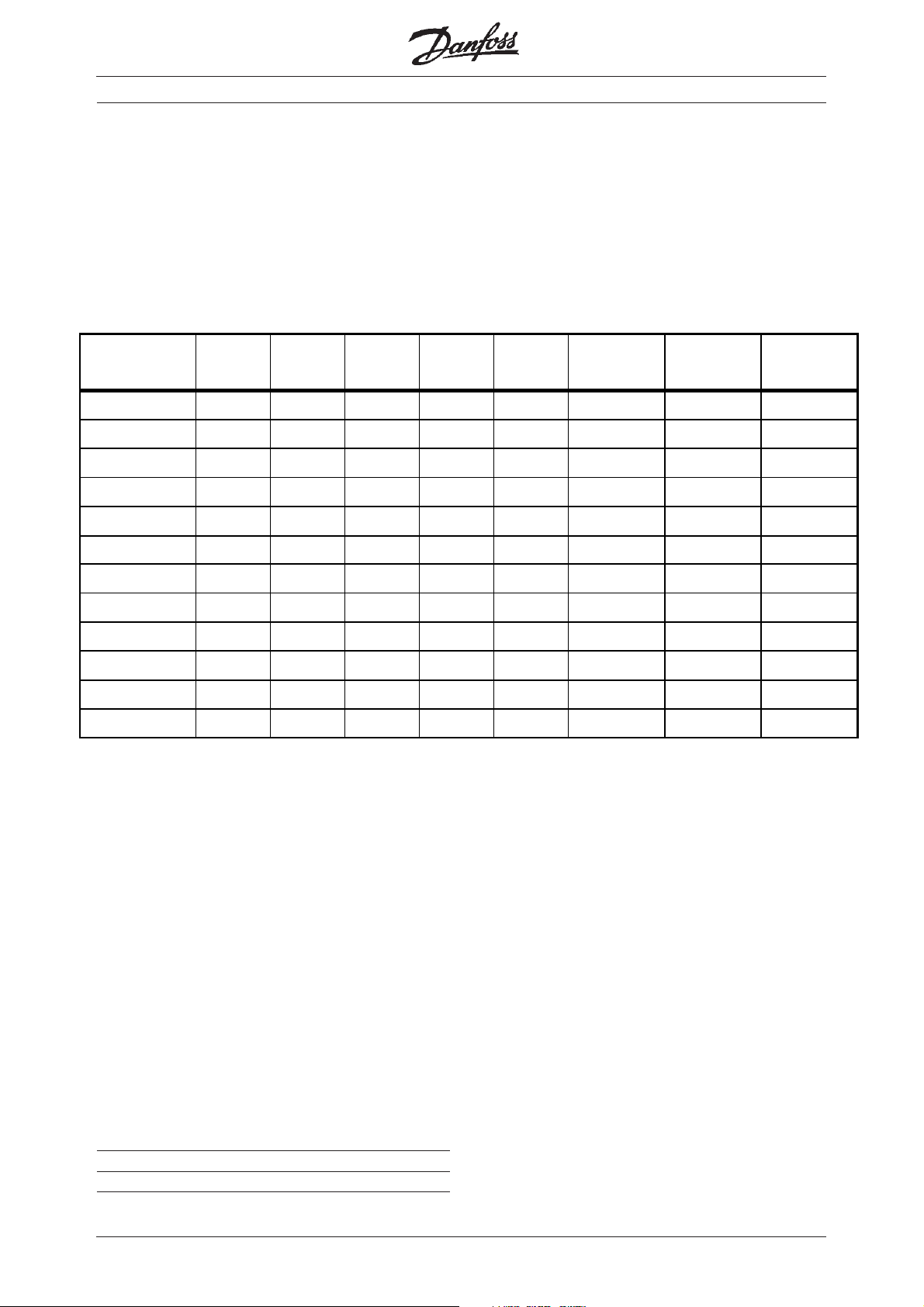
The table shows the supported Fieldbusses:
High Performance FieldBus cards
Profibus DPV0
Profibus DPV1
DMS
300
9Ø9ØØ 9 Ø Ø
FCD
300
FCM
300
999 99
Profibus FMS
Interbus
DeviceNet
AS- i
99
999999
Modbus+
Modbus RTU
9
d
9
e
LonWorks
FC protocol
9999 9 9 9
Metasys N2
L&S FLN
Ø These products still support Profibus DPV0, but
have now been replace with Profibus DPV1.
VLT
2800
VLT
5000
c
9
d
9
VLT
5000
Flux
c
9
VLT 6000
HVAC
c
9
VLT 8000
Aqua
c
9
9
9
e
9
99
9
e
99
f
9
99
9
c Note that the Profibus FMS card has a new
ordering number, see page 26-27.
d Note that the previous Interbus gateway to
Profibus is not available anymore.
e The Modbus RTU need to be install in an external
box by these products. The box is not included.
f VLT 8000 Aqua supports only the LonWorks FTP
card.
Issued by: John Bargmeyer, DD-OSE
Revision: 3.11
Date: 2003-08-13
2
MI.90.I1.02 - VLT is a registered Danfoss trademark
■■
■ Profibus DP V0/V1 card for VLT 5000/6000/8000
■■
This Profibus DP V0/V1 card is only available as a
build in, i.e. if the VLT was produce with a Profibus
card.
Profibus connection for Bookstyle
LD1LD2
High Performance FieldBus cards
Termination of
Profibus
Profibus connection for Compact
LD4
LD3
Address switch
OFF = 0
ON = 1
MI.90.I1.02 - VLT is a registered Danfoss trademark
3

■■
■ Profibus DP V0/V1 card for VLT 5000/6000/8000
■■
This Profibus DP V0/V1 card is used in conjunction
with a memory card or Sync./Pos card.
High Performance FieldBus cards
■■
■ Profibus DPV0 card for FMS support
■■
This Profibus DPV0 card is available to support
installations that use the Profibus FMS protocol.
4
MI.90.I1.02 - VLT is a registered Danfoss trademark
Profibus data
■■
■ Profibus connection
■■
High Performance FieldBus cards
■■
■ Cable specification
■■
- Impedance: 135 to 165 ohm at a measuring
frequency from 3 to 20 MHz
- Resistance: < 110 ohm/km
- Capacitance: < 30 pF/m
- Damping: max. 9 dB over the whole wire
length
- Cross section: max. 0.34 mm
corresponding to AWG 22
- Cable type: twisted in pairs,
1 x 2, or 2 x 2, or 1 x 4 wires
- Screening: Copper-braided screen
or braided screen and foil screen
2
,
62 = RxD/TxD-P red cable
63 = RxD/TxD-N green cable
■■
■ Profibus termination
■■
By 'ON' is the bus termination active.
■ LEDs
There are 4 LEDs on the PROFIBUS option card:
LD1 and LD4: Flashes when the card is
communicating.
LD2 and LD3: Lights up when the card is initialized
and ready to communicate. They will
flash while auto baudrate detection is
attempting to detect the actual
baudrate.
It is recommended to use the same cable type in
the entire network to avoid impedance mismatch.
■■
■ Technical data
■■
Baudrate ..................................... 9.6 - 12000 kBaud
Adress area .................................................... 0 - 125
■■
■ Profibus literature
■■
Operating Instruction .......................... MG.90.G1.02
DPV1 Design Guide ............................. MG.90.E2.02
Siemens S7 PLC .................................. MC.50.A2.02
Siemens S5 IM 308C ...........................MC.50.C1.02
SST-PFB-PLC5 Profibus master .......... MN.51.U1.02
GE Fanuc Series 90-30 ......................... MI.50.X1.02
■■
■ GSD files
■■
GSD files are available on the internet at:
http://www.danfoss.com/drives
■ Cable length
Transmission speed Max. total cable length [m]
9.6 - 187.5 kBaud 1000
500 kBaud 400
1.5 MBaud 200
3-12 MBaud 100
Note that theese cable lengths are for 1 segment
with 31 VLT frequency converter.
MI.90.I1.02 - VLT is a registered Danfoss trademark
5
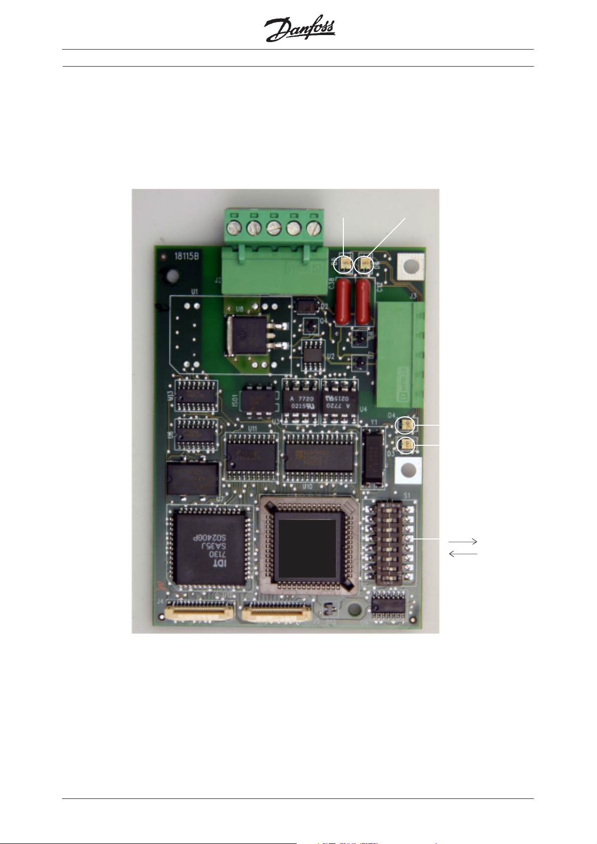
■■
■ Interbus card VLT 5000
■■
High Performance FieldBus cards
Interbus connection for Bookstyle
IBS IN IBS OUT
DC/DC
converter
TR
CC/CR
UL
RD
BA
UL
RD
Interbus connection for Compact
SUPI component for
Interbus communication
IBS OUT IBS IN
BA
CC/CR
TR
6
MI.90.I1.02 - VLT is a registered Danfoss trademark
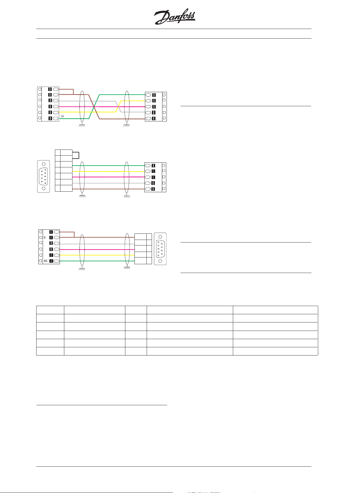
Interbus data
■■
■ Interbus connection
■■
RB
66
62
63
64
65
VLT 5000 to VLT 5000
6
9
DB9 (male) to VLT 5000
RBST
COM
DI
/DI
DO
/DO
9
5
/DO
6
1
1
DO
7
/DI
2
DI
5
3
COM
GreenGreen
Green
GreenGreen
GrayGray
Gray
GrayGray
PinkPink
Pink
PinkPink
YY
ellowellow
Y
ellow
YY
ellowellow
BrownBrown
Brown
BrownBrown
GreenGreen
Green
GreenGreen
YY
ellowellow
Y
ellow
YY
ellowellow
PinkPink
Pink
PinkPink
GrayGray
Gray
GrayGray
BrownBrown
Brown
BrownBrown
/DO
DO
/DI
DI
COM
/DO
DO
/DI
DI
COM
High Performance FieldBus cards
■ Cable length
Max. total cable length ........................ 12.8 km (Cu)
65
64
63
62
66
65
64
63
62
66
Max. length between nodes ........................... 400 m
■■
■ Cable specification
■■
- Impedance: 135 to 165 ohm at a measuring
- Resistance: < 110 ohm/km
- Capacitance: < 30 pF/m
- Damping: max. 9 dB over the whole wire
- Cross section: max. 0.34 mm
- Cable type: twisted in pairs,
- Screening: Copper-braided screen
frequency from 3 to 20 MHz
length
2
,
corresponding to AWG 22
3 x 2 wires
or braided screen and foil screen
RB
66
62
63
64
65
RBST
COM
DI
/DI
DO
/DO
BrownBrown
Brown
BrownBrown
GrayGray
Gray
GrayGray
PinkPink
Pink
PinkPink
YY
ellowellow
Y
ellow
YY
ellowellow
GreenGreen
Green
GreenGreen
COM 3
DI
/DI
DO
/DO
the entire network to avoid impedance mismatch.
1
6
2
7
1
5
6
■■
■ Technical data
■■
9
Baudrate ..................................................500 kBaud
VLT 5000 to DB9 (female)
■ LEDs
It is recommended to use the same cable type in
NameName
Name
NameName
IndicatesIndicates
Indicates
IndicatesIndicates
ColorColor
Color
ColorColor
OnOn
On
OnOn
OFFOFF
OFF
OFFOFF
CC/CR: Cable Check. Green Incomming bus active Incomming bus swicthed off
BA Bus Active. Green Bus active Bus stopped
RD: Status of outgoing bus. Red Outgoing bus stopped Outgoing bus active
TR: Transmit/Receive. Green PCP Communication running NO PCP Communication running
UL: Power OK. Green Voltage within permissable range No Voltage
■■
■ Interbus literature
■■
Operating Instruction .......................... MG.10.O2.02
Interbus CMD ......................................MN.50.U1.02
MI.90.I1.02 - VLT is a registered Danfoss trademark
7
■■
■ DeviceNet card for VLT 5000/6000/8000
■■
DeviceNet connection
High Performance FieldBus cards
for Bookstyle
Device status
LED
Network status
LED
DeviceNet connection
for Compact
Device status LED
Network status LED
Address switch and
baud rate setting
OFF = 1
ON = 0
8
MI.90.I1.02 - VLT is a registered Danfoss trademark
High Performance FieldBus cards
5 V+
4 CAN_H
3 drain
2 CAN_L
1 V–
red
white
bare
blue
black
1 2 3 4 5
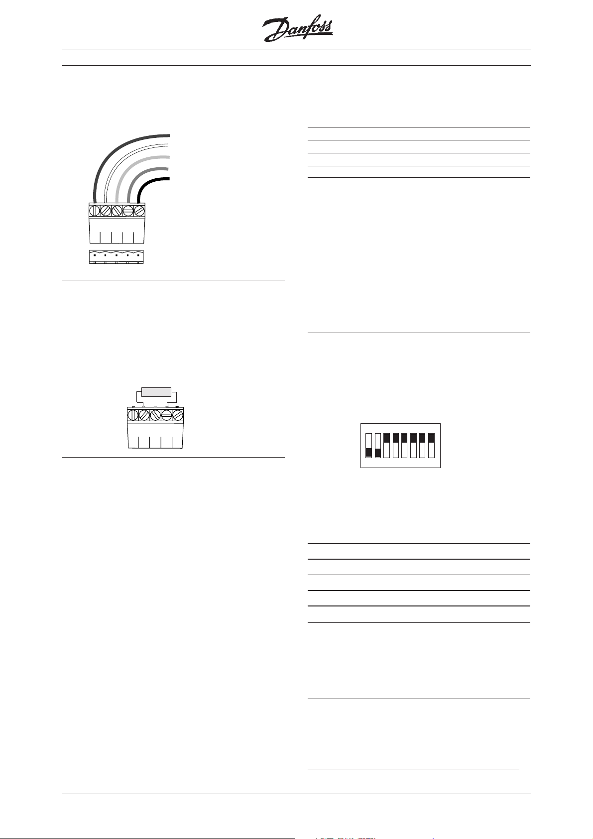
DeviceNet data
■■
■ DeviceNet connection
■■
■■
■ DeviceNet termination
■■
Termination resistors should be installed at each end
of the bus line.
The resistors shall be mount between terminal 2
CAN_L and terminal 4 CAN_H and should have the
following specification:
121 Ohm, 1 % Metal film and 1/4 Watt
■ Cable length
Transmission speed Max. total cable length [m]
125 kBaud 500
250 kBaud 250
500 kBaud 100
■■
■ Cable specification
■■
- Cross section: max. 0.78 mm
2
,
corresponding to AWG 18
- Cable type: twisted in pairs, 2 x 2 wires with
drain wire in center
- Screening: Copper-braided screen
or braided screen and foil screen
It is recommended to use the same cable type in
the entire network to avoid impedance mismatch.
■■
■ Address and baud rate setting
■■
Dip switch 1-6 set the VLT frequency converters
address and 7-8 the baud rate.
If the address shall be set to 3 the dip switches
should be set as follow:
■ LEDs
For the device status LED:
1. when the LED is off, the device is off
2. when the LED is green, the device is
operational
3. When the LED is flashing green, the device
is in standby
4. when the LED is flashing red, the device
detects a minor fault
5. when the LED is red, the device detects
an unrecoverable fault
6. when the LED is flashing red/green, the
device is self testing
For the network status LED:
1. when the LED is off, the network is non-
powered/not online
2. when the LED is flashing green, the
network is online but not connected
3. when the LED is green, the network is
4. when the LED is flashing red, the network
online and connected
has a connection time-out
5. when the LED is red, the network has a
critical link failure.
ON
ON = 0
OFF = 1
8
12345
6
7
Switch Settings for DeviceNet Module Baud Rate:
Baud Switch Switch
Rate Setting Setting
87
125 kBPS 0 0
250 kBPS 0 1
500 kBPS 1 0
125 kBPS 1 1
■■
■ DeviceNet literature
■■
Operating Instruction .......................... MG.50.H4.22
Allen-Bradley SLC 500 .........................MC.50.D1.02
Allen-Bradley Control logix ................... MN.51.T1.02
■■
■ EDS files
■■
EDS files for each product series are available on
the internet at:
http://www.danfoss.com/drives
MI.90.I1.02 - VLT is a registered Danfoss trademark
9
High Performance FieldBus cards
■■
■ Modbus+ card VLT 5000 Bookstyle
■■
Network LED
Top connector
Address switch
■■
■ Modbus+ card VLT 5000 Compact
■■
Network LED
Side connector
Address switch
10
MI.90.I1.02 - VLT is a registered Danfoss trademark

High Performance FieldBus cards
E
Modbus Plus data
■■
■ Modbus connection
■■
3 Blue
2 Drain
3 2 1
NOTE: Drain wire and shield should be
insulated.
■■
■ Modbus termination
■■
It is essential that the bus line be terminated
properly. A mismatch of impedance may result in
reflections on the line that will corrupt data
transmission.
The Modbus Plus Option card is provide with a
pluggable screw connector for 176F1551 (Compact
units) and a DB9 connector for 176F1550 (Bookstyle units).
An adaptor cable number 190703 is required for use
with 176F1551.
Mating network connectors should be ordered from
MODICON:
P/N AS-MBKT-085, (1) in-line connector
P/N AS-MBKT-185, (2) terminating connectors
1 White
■ LEDs
• Three flashes, then OFF for 1.7 seconds;
The node is not hearing any other nodes. It
is periodically claiming the token, but finding
no other node to which to pass it. Check
the network for an open circuit or defective
termination.
• Four flashes, then OFF for 1.4 seconds;
The node has heard a valid message from
another node that is using the same
address as this node. The node remains in
this state as long as it continues to hear the
duplicate address. If the duplicate address
is not heard for five seconds, the node then
changes to the pattern of one flash every
second.
NOTE: LED patterns other than those shown
above indicate a possible hardware problem.
■■
■ Cable specification and length
■■
The recommended Modbus Plus cable is Belden
9841, shielded twisted pair.
Minimum length between nodes ........................ 3 m
Maximum length without repeaters ................ 450 m
■■
■ Address and baud rate setting
■■
Dip switch 1-6 set the VLT frequency converters
address. Dip switch are not 7-8 used.
ON
ON = 0
OFF = 1
1234567
8
■ LEDs
Modbus Plus status is shown by flashing a
repetitive pattern on the network indicator (green
LED). The patterns are:
• Six flashes per second;
The node's normal operating state. The
node is successfully receiving and passing
the token. All nodes on the network should
be flashing this pattern.
• One flash per second;
The node is off-line after just being powered
up, or after exiting the four flashes per
second mode.
• Two flashes, then OFF for two seconds;
The node is hearing the token being passed
among other nodes, but is never receiving
the token. Check the network for an open
circuit or defective termination.
MI.90.I1.02 - VLT is a registered Danfoss trademark
The address of the VLT frequency converter will be
L
one higher than the binary value. With the above
settings of the dip switches the address will be 4.
NOTE: Changes in switch settings are only active
after power up.
■■
■ Modbus Plus literature
■■
Operating Instruction .......................... MG.10.M1.22
Modbus ............................... Modbus Plus Tech note
11

■■
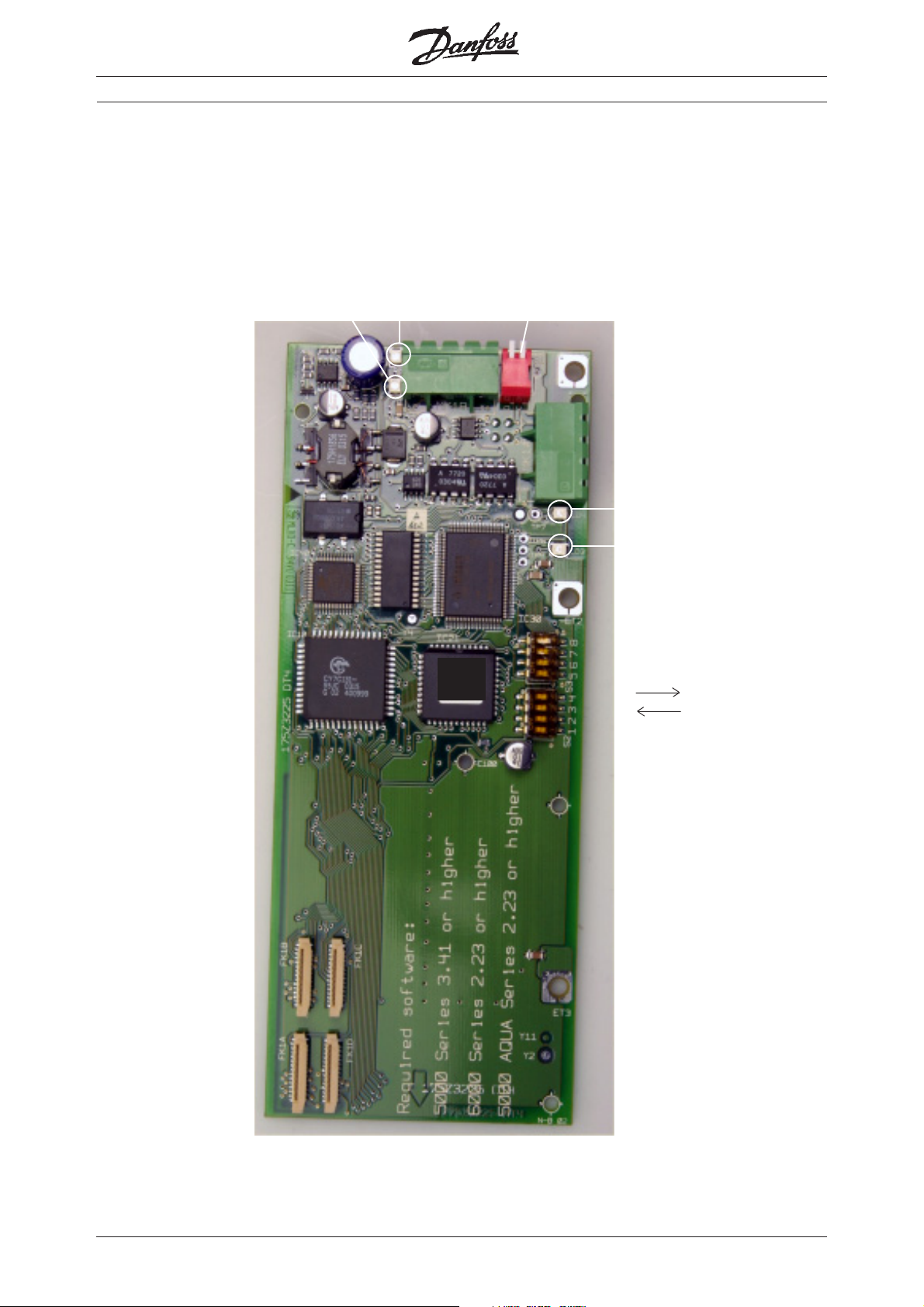
■ Modbus RTU card
■■
The Modbus RTU option card is a gateway that
translates Modbus RTU telegrams to Danfoss FC
protocol. As the FC protocol is integrated in all VLT
frequency converts as standard, the Modbus RTU
can interface to all our drives except for the DMS
300.
The Modbus RTU can be built into the control
cassette of the following products:
High Performance FieldBus cards
● VLT 5000
● VLT 6000 HVAC
● VLT 8000 AQUA
With VLT 5000 Flux, VLT 2800, FCM 300 the
Modbus RTU card must be mounted into an
external box.
The code number for the Modbus RTU option card
is 175Z3362.
Modbus RTU
connector
Modbus LED
Modbus RTU
connector
VLT LED
Address and
termination
Baud rate
and Parity
12
Connector to
VLT terminals
MI.90.I1.02 - VLT is a registered Danfoss trademark

High Performance FieldBus cards
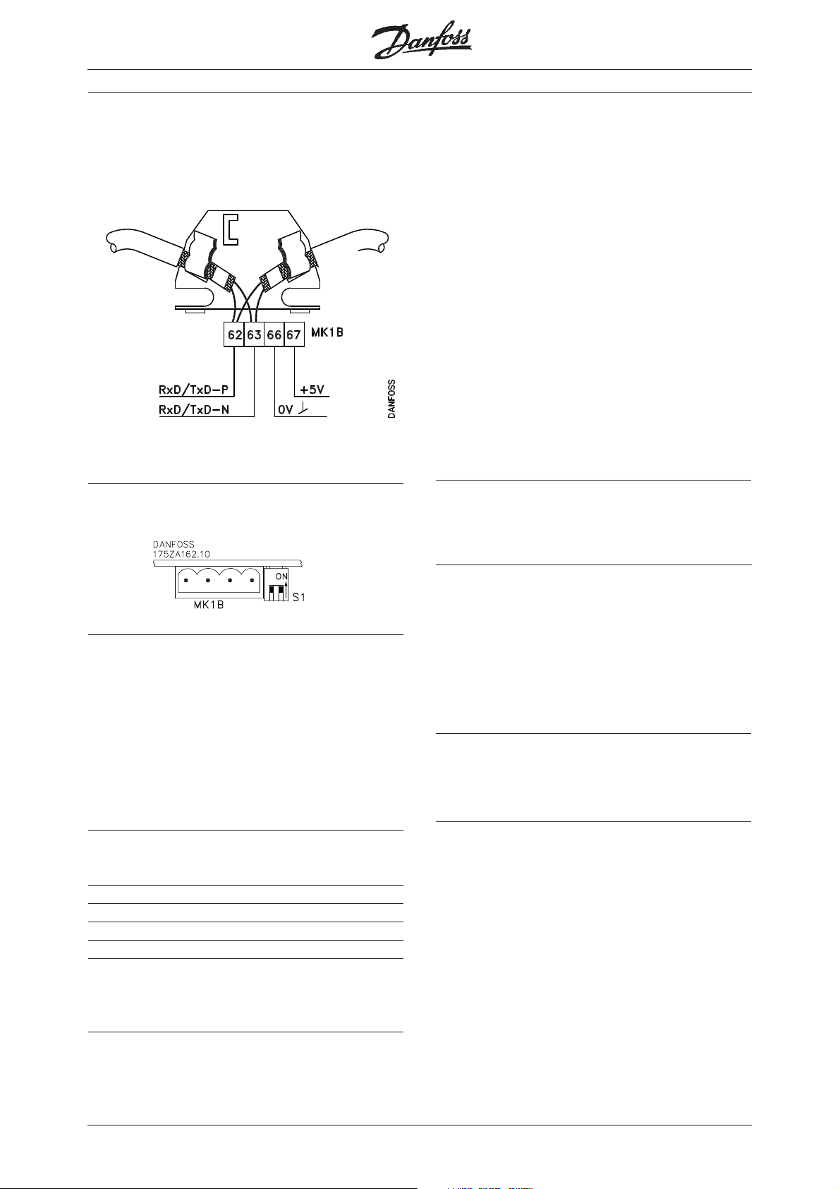
Modbus RTU data
■■
■ Modbus RTU connection
■■
RT xD' (-)
Com
RTxD (+)
■■
■ Connector from Modbus RTU to VLT
■■
24V in
RTxD
Com
RTxD'
■ LEDs
There are 2 LEDs on the Modbus RTU option card.
Both LEDs use the same communication pattern:
• Flashing Green (1 Hz): Communication online
(VLT LED) or receiving data (Modbus LED).
to terminal 12 or 13
to terminal 69 (+)
to terminals 39 and 61
to terminal 68 (-)
(spare)
(spare)
■ Baud rate and parity Dip switch
This Dip switch sets the baud rate and the parity on
the Modbus network.
The baud rate can be set to 4800, 9600 (default) or
19200 baud by switches 1-3.
The parity bit can be set to None, Odd or Even
(default) by switches 4-5.
See the Modbus manual for the Dip switch settings.
Switches 6-8 are reserved switches.
■ Address and termination Dip switch
This Dip switch sets the Modbus address and the
termination.
The address can be set by switches 1-8. Default
address is 1.
The termination can be set by switch 9. Default
termination is ON.
See the Modbus manual for the Dip switch settings.
• Flashing Red (1 Hz): Communication time out
• Solid Red: Major fault, communication stopped
■ VLT parameter settings
As the Modbus RTU card interface to the built-in
RS-485 FC profile the following parameters must be
set in the VLT:
VLT 5000/VLT 2800/FCD 300/FCM 300:
Parameter 500 Address: 001
Parameter 501 Baud rate: 9600 baud
Parameter 512 Profile: FC protocol
VLT 6000/VLT 8000
Parameter 500 Profile: FC protocol
Parameter 501 Address: 001
Parameter 502 Baud rate: 9600 baud
MI.90.I1.02 - VLT is a registered Danfoss trademark
13

■■
■ Lonworks cards VLT 5000/6000/8000 Free Topology
■■
High Performance FieldBus cards
Termination of
LonWorks
Status and
Service LED
LonWorks connection
for Bookstyle
Service Pin
Status and
Service LED
LonWorks connection
for Compact
Service Pin
14
MI.90.I1.02 - VLT is a registered Danfoss trademark

LonWorks data for FTP
■■
■ LonWorks connection
■■
High Performance FieldBus cards
Flashing 5 times per secondFlashing 5 times per second
Flashing 5 times per second
Flashing 5 times per secondFlashing 5 times per second
The response to the network management “Wink”
command. The VLT LonWorks node must be reset
to leave the wink state.
61
80
Net B 80
79
Net A 79
Connect signal wires to terminal 79 and to 80 of the
terminal connector. In free topology model,
connections can be reversed.
■■
■ Lonworks termination
■■
The option card has a termination resistor built-in
which is activated by a terminator switch. Use of
the terminator is optional, depending upon the
network configuration. If termination is provided
elsewhere in the network, the termination function
should be OFF. Terminator switch position functions
are provided in the table below.
TT
erminationermination
T
ermination
TT
erminationermination
No termination Net Term Off Don’t Care
Single termination Net Term On Net Term Off
Double termination Net Term On Net Term On
■ LEDs
There are 2 LEDs on the LonWorks option card:
Green LED: Status LED
Red LED: Service LED, see LonWorks manual.
Pos 1Pos 1
Pos 1
Pos 1Pos 1
Pos 2Pos 2
Pos 2
Pos 2Pos 2
OFF
No power on board or hardware fault.
■ Cable length
Free Topology Specifications
Maximum Maximum
node-to-node distance total wire length
Belden 85102 500 m 500 m
Belden 8471 400 m 500 m
Level IV, 22AWG 400 m 500 m
JY (St) Y 2x2x0.8 320 m 500 m
Maximum bus length for segments with FTT-10
transceivers and with both FTT-10 and LPT-10
transceivers.
FTT-10 FTT-10 and
transceivers only LPT-10 transceivers
Belden 85102 2700 m 2200 m
Belden 8471 2700 m 2200 m
Level IV, 22AWG 1400 m 1150 m
JY (St) Y 2x2x0.8 900 m 750 m
Danfoss recommends the use of shielded LonWorks
communication cable for instance Belden 8719.
The Status LED patterns are:
ONON
ON
ONON
There is power on the board but there has not been
any communication to an input network variable in
the last 2 seconds.
Flashing 10 times per secondFlashing 10 times per second
Flashing 10 times per second
Flashing 10 times per secondFlashing 10 times per second
There is regular network communication to the
VLT’s input network variables.
Flashing intermittentlyFlashing intermittently
Flashing intermittently
Flashing intermittentlyFlashing intermittently
There is network communication to the VLT’s input
network variables but input network variables are
received at a period greater than 2 seconds.
MI.90.I1.02 - VLT is a registered Danfoss trademark
■■
■ LonWorks literature
■■
Operating Instruction .......................... MG.60.N1.02
LonMaker .............................................. MI.60.L1.02
■■
■ Xif files
■■
Xif files are available on the internet at:
http://www.danfoss.com/drives
15

High Performance FieldBus cards
■■
■ Lonworks cards VLT 5000/6000 78 kbps and 1.25 Mbps
■■
Terminator
switch
Status LED
Service pin
Status LED
Service pin
16
MI.90.I1.02 - VLT is a registered Danfoss trademark

LonWorks data for 78 kbps and
1.25 Mbps
■■
■ LonWorks connection
■■
High Performance FieldBus cards
Flashing 5 times per secondFlashing 5 times per second
Flashing 5 times per second
Flashing 5 times per secondFlashing 5 times per second
The response to the network management “Wink”
command. The VLT LonWorks node must be reset
to leave the wink state.
61
80
Net B 80
79
Net A 79
Connect signal wires NET A to terminal 79 and NET
B to 80 of terminal connector.
■■
■ Lonworks termination
■■
The option card has a termination resistor built-in
which is activated by a terminator switch. Use of
the terminator is optional, depending upon the
network configuration. If termination is provided
elsewhere in the network, the termination function
should be OFF. Terminator switch position functions
are provided in the table below.
Switch 1:
Network TNetwork T
Network T
Network TNetwork T
The VLT LonWorks node is terminated.
ermination ONermination ON
ermination ON
ermination ONermination ON
OFFOFF
OFF
OFFOFF
No power on board or hardware fault.
■ Cable length
78 kbps and 1.25 Mbps Specifications
78 kbps 1.25 Mbps
Network bus lenght, Typical 2000 m 500 m
Network bus lenght, Worst case 1330 m 125 m
■■
■ Cable specification
■■
Network Bus Wiring UL Level IV, 22 AWG (0.65 mm)
twisted pair
Network Stub Wiring UL Level IV, 22 or 24 AWG (0.5
mm) twisted pair
Danfoss recommends the use of shielded LonWorks
communication cable for instance Belden 8719.
Network TNetwork T
Network T
Network TNetwork T
The VLT LonWorks node is not terminated.
■ LEDs
There are 2 LEDs on the LonWorks option card:
Green LED: Status LED
Red LED: Service LED, see LonWorks manual.
The Status LED patterns are:
ONON
ON
ONON
There is power on the board but there has not been
any communication to an input network variable in
the last 2 seconds.
Flashing 10 times per secondFlashing 10 times per second
Flashing 10 times per second
Flashing 10 times per secondFlashing 10 times per second
There is regular network communication to the
VLT’s input network variables.
Flashing intermittentlyFlashing intermittently
Flashing intermittently
Flashing intermittentlyFlashing intermittently
There is network communication to the VLT’s input
network variables but input network variables are
received at a period greater than 2 seconds.
ermination OFFermination OFF
ermination OFF
ermination OFFermination OFF
■■
■ LonWorks literature
■■
Operating Instruction ........................... MG.60.E4.02
LonMaker .............................................. MI.60.L1.02
■■
■ Xif files
■■
Xif files are available on the internet at:
http://www.danfoss.com/drives
MI.90.I1.02 - VLT is a registered Danfoss trademark
17

■■
■ VLT 2800 fieldbus cards.
■■
High Performance FieldBus cards
18
Profibus card DeviceNet card
MI.90.I1.02 - VLT is a registered Danfoss trademark
Plugable DeviceNet
connector.

High Performance FieldBus cards
VLT 2800 Profibus card
■■
■ VLT 2800 Profibus connection
■■
68 = RxD/TxD-P red cable
69 = RxD/TxD-N green cable
■■
■ Technical data
■■
Baudrate ........................................ 9.6 - 3000 kbaud
Adress area .................................................... 0 - 125
VLT 2800 DeviceNet card
■■
■ VLT 2800 DeviceNet connection
■■
■■
■ Drop cable
■■
An alternative to splicing two trunk lines in the connector on the control card, is using a DeviceNet
connection box or a T-connector. For this kind of installation a drop cable is available as an option.
■■
■ 12 M baud Profibus card
■■
VLT 2800 can also be delivered with a 12 M baud
Profibus control card.
Order number: .......................................... 195N0603
The order number is only for the control card with
12 M baud Profibus. The power part should be order
separately.
For other technical data on Profibus, see page 5
Profibus Data.
Drop cable ordering number: 195N3113
For other technical data on DeviceNet, see page 9
DeviceNet Data.
MI.90.I1.02 - VLT is a registered Danfoss trademark
19
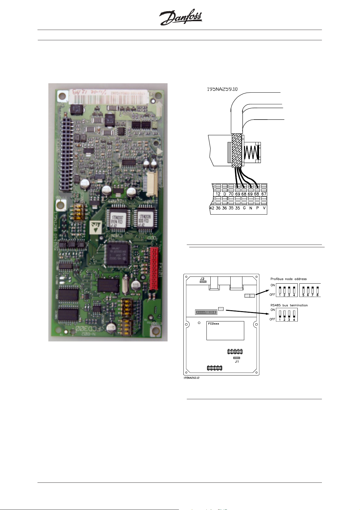
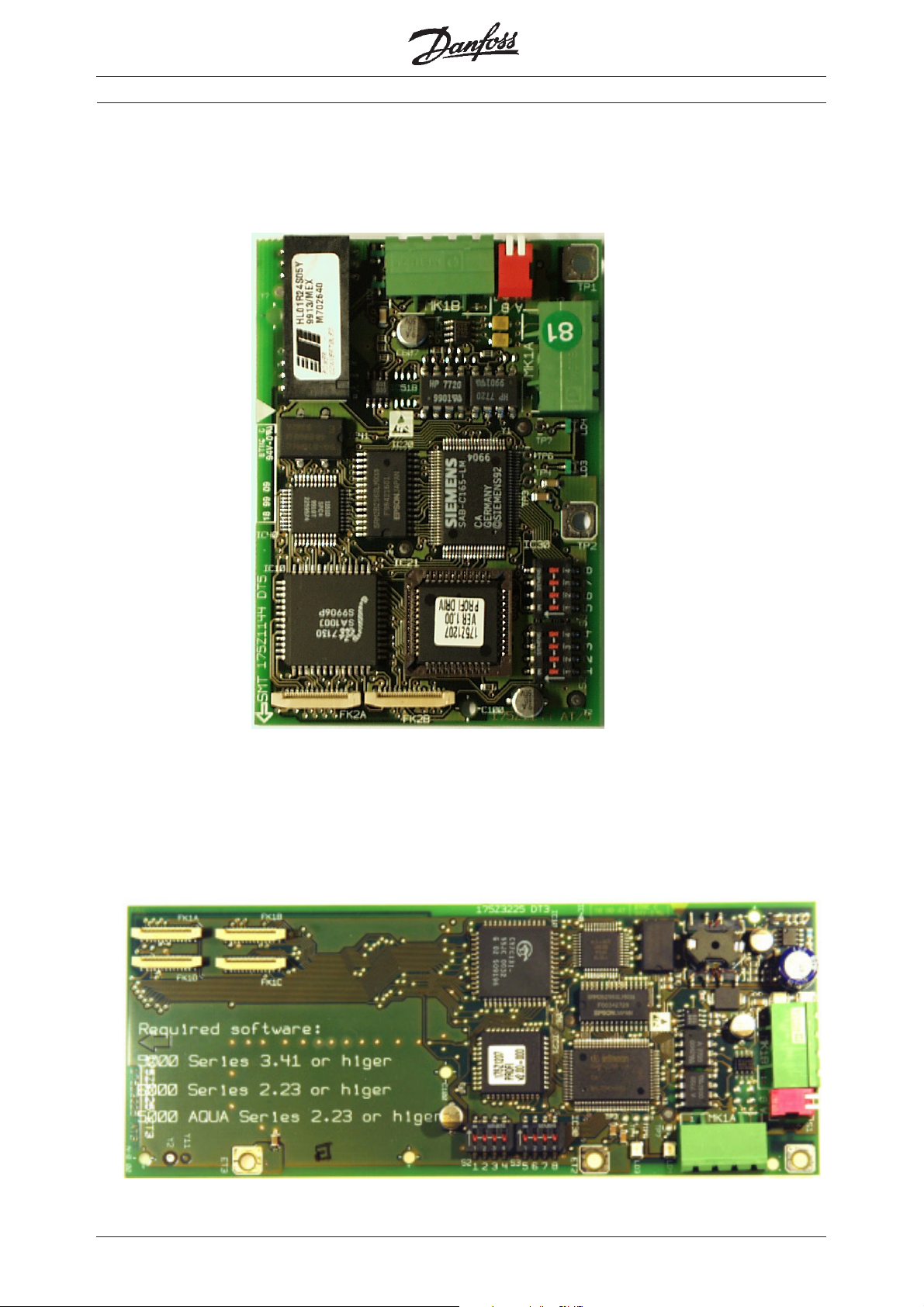
■■
■ FCD 300 Profibus card
■■
High Performance FieldBus cards
■■
■ FCD 300 Profibus connection
■■
Profibus card
68 = RxD/TxD-P red cable
69 = RxD/TxD-N green cable
■■
■ FCD 300 DIP switches
■■
20
MI.90.I1.02 - VLT is a registered Danfoss trademark

■■
■ FCD 300 DeviceNet card
■■
High Performance FieldBus cards
■■
■ FCD 300 DeviceNet connection
■■
Terminal Colour Func tion
67 Red 24 Volt
68 White Can_high
69 Blue Can_low
70 Black GND
DBar Drain
DeviceNet card
■■
■ FCD 300 Plug 175N2279
■■
The DeviceNet bus connection can be performed
through a plug, that is to be mounted in the
FCD 300 housing (M16 gland hole) and wired
to the inside terminal strip.
MI.90.I1.02 - VLT is a registered Danfoss trademark
21

■■
■ FCD 300 AS-i bus card
■■
High Performance FieldBus cards
■■
■ FCD 300 AS-i connection
■■
The AS-I bus lines are to be connected to terminals
68 and 69 of the internal terminal strip. A round drop
cable can be wired directly into the terminals by
using a cable gland. A sealed M12 connector can
be mounted into one of the M16 gland holes in the
FCD enclosure. The M12 connector is to be wired
to the terminals 68, 69 on the control terminal
block. The connection is in the following way:
AS-i + to 68
AS-i - to 69.
■■
■ FCD 300 AS-i Plug 175N2281
■■
The AS-i bus connection can be performed
through a plug, that is to be mounted in the
FCD 300 housing (M16 gland hole) and wired
to the inside terminal strip.
Pin 1 (Brown) to AS-i + (68)
Pin 3 (Blue) to AS-i - (69)
22
AS-i bus card
MI.90.I1.02 - VLT is a registered Danfoss trademark

■■
■ DMS 300 Profibus card
■■
High Performance FieldBus cards
■■
■ AKD Lon card
■■
Profibus connection
Profibus termination
The AKD Lon card can only be used together with
AKD 2800 and AKD 5000.
Adap-Kool
Lon connector
Connector to
VLT terminals
MI.90.I1.02 - VLT is a registered Danfoss trademark
23

■■
■ Miscellaneous, Accessories to Fieldbus
■■
VLT 3000 to 5000 converter software (17.1x):
The VLT 3000 to 5000 converter is a special
software version which is intended to convert a VLT
3000 to a VLT 5000, which replaces the VLT 3000.
The converter software is typical used to replace a
VLT 3000 with a Profibus interface, but it can also
replace a VLT 3000 in a RS-485 network.
With the converter software we only support
Profibus DP Norm, so a replaced VLT 3000 should
have a software version 3.00 or higher.
The software version number can be read out in
parameter 603, choice 3.
To purchase (obligatory):
● VLT 5000 ................................................ 175XXXXX
● Converter software 17.1x ....................... 175z3389
High Performance FieldBus cards
Optional:
● Profibus option excl. memory option ...... 175z0402
● Backplate for 5001-5005 Compact IP 20
ordering no. ................................................ 175Z2349
● Separate relay card ................................. 175Z1814
If two high voltage relays are needed in VLT 5000 a
separate relay card must be purchased.
● Ordering number ..................................... 176F1814
See also the VLT 3000 to 5000 converter manual
MG.50.Q1.02.
24
MI.90.I1.02 - VLT is a registered Danfoss trademark

■■
■ Miscellaneous, Accessories to Fieldbus
■■
High Performance FieldBus cards
Profibus kit for SUB D9 connection:
This kit can be mounted together with a VLT 5000/
6000/8000 Profibus card and the standard SUB D9
Profibus connector can be used.
Product Ordering number
VLT 5001-5027 230 V ............................... 175Z3568
VLT 5032-5052 230 V ............................... 176F1822
VLT 5001-5102 400 V ............................... 175Z3568
VLT 5125-5500 400 V ............................... 176F1822
VLT 6002-6032 230 V ............................... 175Z3568
VLT 6042-6072 230 V ............................... 176F1822
VLT 6002-6122 400 V ............................... 175Z3568
VLT 6150-6550 400 V ............................... 176F1822
VLT 8002-8032 230 V ............................... 175Z3568
VLT 8042-8072 230 V ............................... 176F1822
VLT 8002-8122 400 V ............................... 175Z3568
VLT 8150-8550 400 V ............................... 176F1822
Top connection of Fieldbus by IP 20 Unit:
It is now possible to make a top connection of the
Fieldbus cable by all IP 20 units by VLT 5000/6000/
8000. The connection will be similar to a book style
connection.
The top connection can be done on all VLT 5000/
6000/8000 IP 20 unit that are produce from the
week 15 2003 (G363) except VLT 5032-5052 230 V,
VLT 5125-5500 400 V, VLT 6042-6072 230 V, VLT
6150-6550 400 V, VLT 8042-8072 230 V and VLT
8150-8550 400 V.
Top connection on VLT 5072-5102, 6102-6122 and
8102-8122 is available from week 36 2003.
It is also possible to retrofit VLT 5000/6000/8000 IP
20 unit with a clamp (175Z3477), so that a top
connection can be done.
In this case the Drive need to be produce after
week 23 2002 (G232)
By VLT 5072-5102, 6102-6122 and 8102-8122 can
the kit first by install from week 36 2003 (G363).
MI.90.I1.02 - VLT is a registered Danfoss trademark
Ordering number 175Z3477
25

High Performance FieldBus cards
Fieldbus options ordering number for VLT 5000:
■
Profibus DPV1:
Type Description Ordering no. Ordering no. with conformal coating
Profibus option DPV1 Incl. memory option 175Z0404 175Z2625
Profibus option DPV1 excl. memory option 175Z0402 175Z4363
Profibus FMS:
Type Description Ordering no. Ordering no. with conformal coating
Profibus option FMS Incl. memory option 175Z3722 175Z3723
Interbus:
Interbus option Incl. memory option 175Z3122 175Z3191
Interbus option excl. memory option 175Z2900
DeviceNet:
DeviceNet option Incl. memory option 176F1580 176F1581
DeviceNet option excl. memory option 176F1584
Modbus Plus:
Modbus Plus for Compact units Incl. memory option 176F1551 176F1553
Modbus Plus for Compact units Excl. memory option 176F1559
Modbus Plus for Bookstyle units Incl. memory option 176F1550 176F1552
Modbus Plus for Bookstyle units Excl. memory option 176F1558
LonWorks:
LonWorks option, Free topology Incl. memory option 176F1500 176F1503
LonWorks option, Free topology excl. memory option 176F1512
LonWorks option, 78 KBPS Incl. memory option 176F1501 176F1504
LonWorks option, 78 KBPS excl. memory option 176F1513
LonWorks option, 1.25 MBPS Incl. memory option 176F1502 176F1505
LonWorks option, 1.25 MBPS excl. memory option 176F1514
26
MI.90.I1.02 - VLT is a registered Danfoss trademark

High Performance FieldBus cards
■
Fieldbus options ordering number for VLT 6000 HVAC:
Profibus DPV1:
Type Description Ordering no. Ordering no. with conformal coating
Profibus option DPV1 Incl. memory option 175Z7800 175Z2905
Profibus option DPV1 excl. memory option 175Z0402 175Z4363
Profibus FMS:
Type Description Ordering no. Ordering no. with conformal coating
Profibus option FMS Incl. memory option 175Z4207 175Z4208
LonWorks:
LonWorks option, Free topology Incl. memory option 176F1515 176F1521
LonWorks option, Free topology excl. memory option 176F1512
LonWorks option, 78 KBPS Incl. memory option 176F1516 176F1522
LonWorks option, 78 KBPS excl. memory option 176F1513
LonWorks option, 1.25 MBPS Incl. memory option 176F1517 176F1523
LonWorks option, 1.25 MBPS excl. memory option 176F1514
DeviceNet:
DeviceNet option Incl. memory option 176F1586 176F1587
DeviceNet option excl. memory option 176F1584
■
Fieldbus options ordering number for VLT 8000 Aqua:
Profibus DPV1:
Type Description Ordering no. Ordering no. with conformal coating
Profibus option DPV1 Incl. memory option 175Z3685 175Z3686
Profibus option DPV1 excl. memory option 175Z0402 175Z4363
LonWorks:
LonWorks option, Free topology Incl. memory option 176F0225 LonWorks option, Free topology excl. memory option 176F1512
DeviceNet:
DeviceNet option Incl. memory option 176F0224 DeviceNet option excl. memory option 176F1584
MI.90.I1.02 - VLT is a registered Danfoss trademark
27
■■
■ Previous produce Profibus ca rds
■■
High Performance FieldBus cards
28
MI.90.I1.02 - VLT is a registered Danfoss trademark

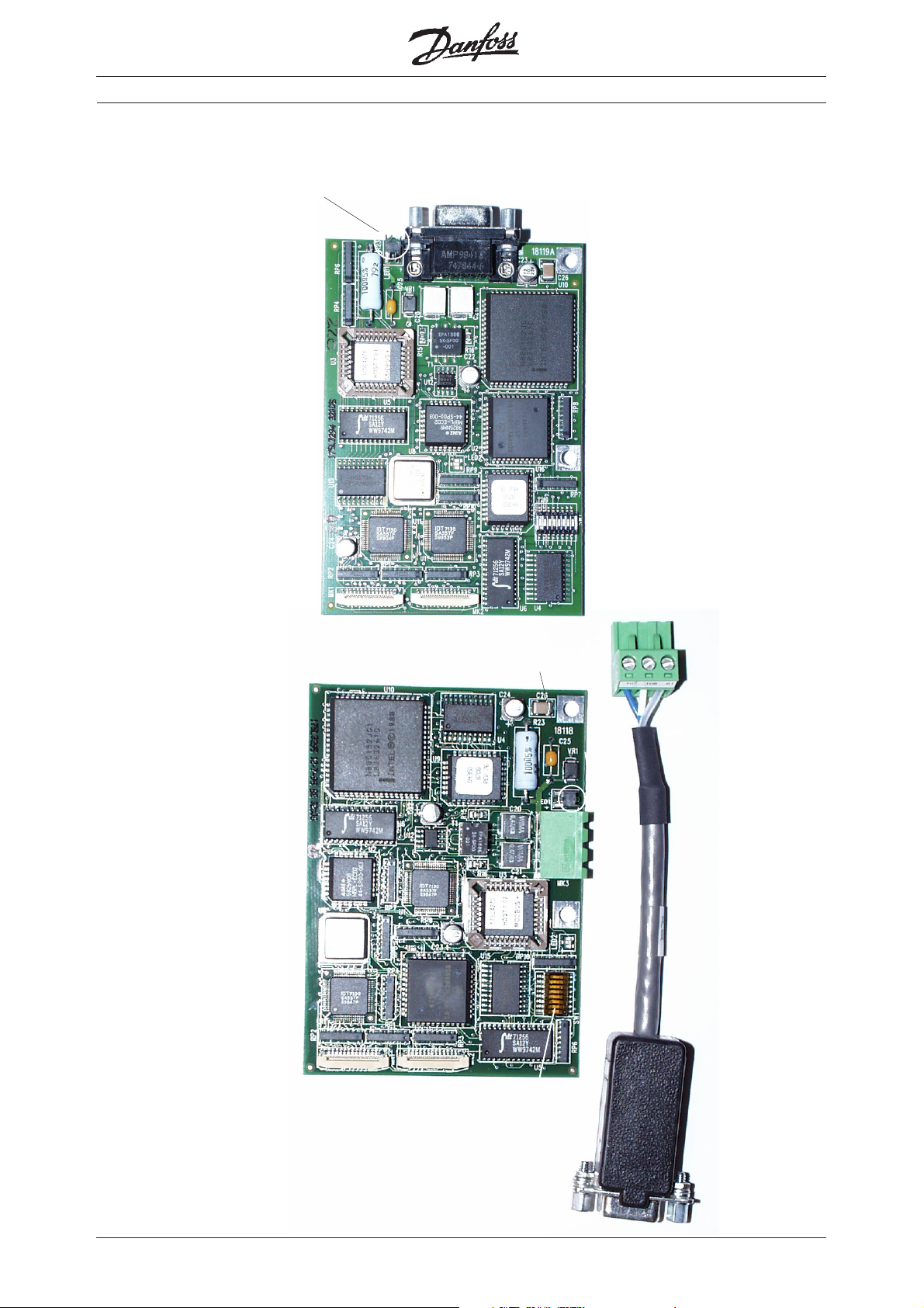
■■
■ Previous produce DeviceNet ca rds
■■
Revisions number
18115A
High Performance FieldBus cards
Revisions number
18115D
MI.90.I1.02 - VLT is a registered Danfoss trademark
29

■■
■ Previous produce LonWorks ca rds
■■
High Performance FieldBus cards
Terminator
Switch
Revision number
18110A
Service Pin
Terminator
Switch
Revision number
18110B
Service Pin
Terminator
Switch
This ferrite coil is
only mounted on
revision C
Revision number
18110C
Service Pin
This capacitor is
only mounted on
revision B.
The capacitor can
also be mounted on
revision A card.
30
MI.90.I1.02 - VLT is a registered Danfoss trademark

■■
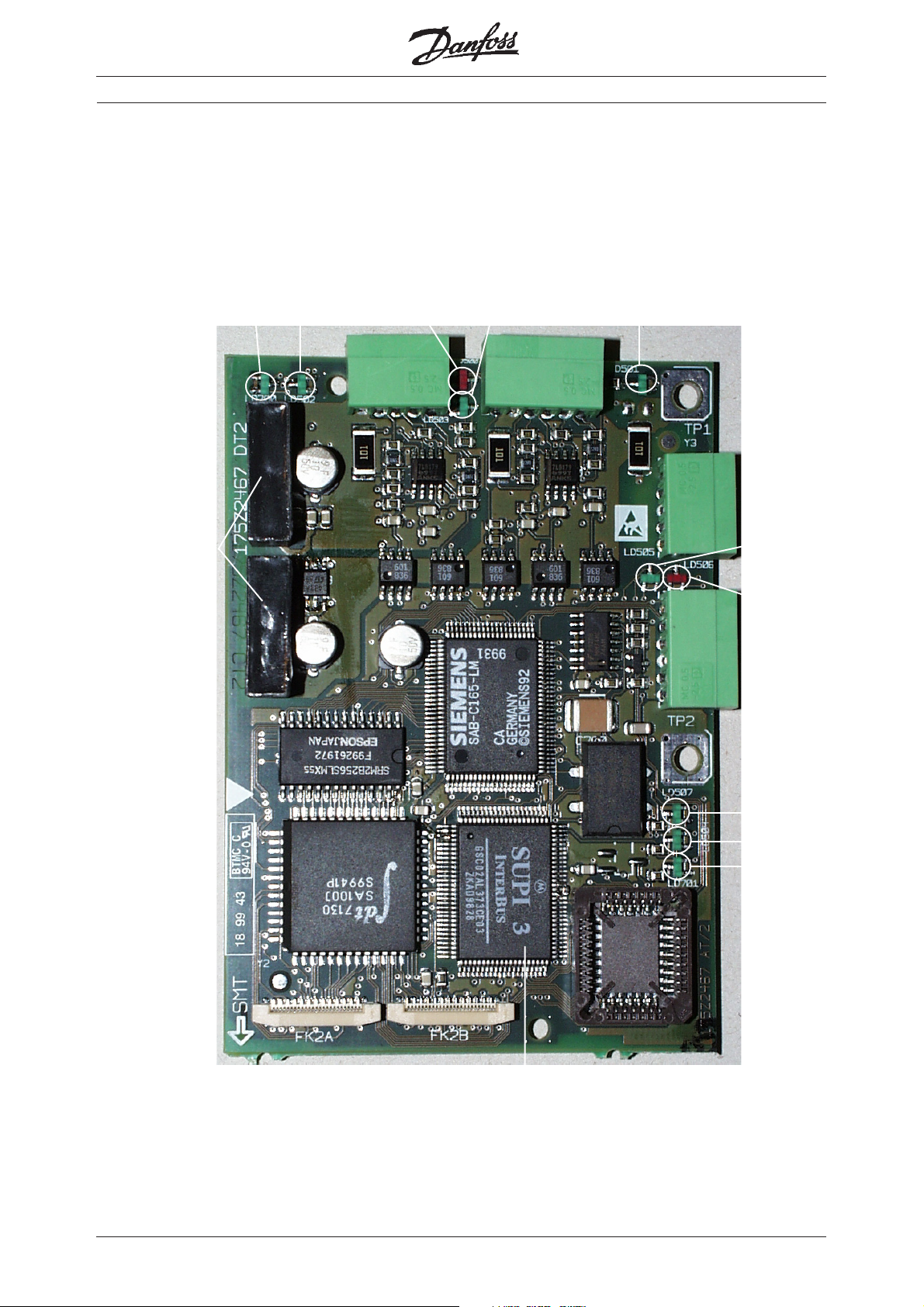
■ Previous produce Modbus RTU ca rds
■■
High Performance FieldBus cards
Modbus RTU
connector
Modbus RTU LED
VLT LED
6-pin connector to
VLT terminals
Address and termination Dip switch
Pin 1
Baud rate and parity
Dip switch
Pin 1
MI.90.I1.02 - VLT is a registered Danfoss trademark
31
 Loading...