

Page 1

Table of Contents
Page
Introduction 2
Safety 2
Section One
Section Two
Section Three Static
Test Procedures
Section Three Dynamic
Test Procedures
Section Four
Description of Operation 5
Sequence of Operation 9
Status Messages 11
Warning Messages 12
Alarm Messages 13
Troubleshooting T ips 17
Flow Charts 18
Symptom/Cause Charts 21
Testing the Soft Charge Circuit 23
Testing the Input Rectifiers 25
Testing the Inverter Section 26
Testing the Heatsink Temperature Sensor 27
Testing for Output Phase Imbalance 27
Testing Gate Drive Firing Circuits 28
Testing Input Rectifiers 30
Testing for Current Feedback 30
Removing and Replacing the Control Card 31
Removing and Replacing the Interface Board 31
Removing and Replacing Gate/Snubber/IGBT 32
Removing and Replacing Input Rectifiers 33
Section Five
Appendix
Current Limit Trips 35
Unstable Motor Operation 35
Ground Fault Trips 37
Overcurrent Trips 37
Overvoltage Trips 38
Overtemperature Trips 39
Additional Fault Codes I
Spare Parts List II
Block Diagram VLT 3032 III
Block Diagram VLT 3042 IV
Block Diagram VLT 3052 V
1
Page 2
INTRODUCTION
The purpose of this manual is to provide technical information and
instructions that will enable the user to identify faults and affect repairs
on Danfoss series 3000 Adjustable Frequency Drives, VL T 3032 through
VLT 3052, 230 Volt models.
The manual has been divided into five sections. The first section covers
the description and sequence of operations. Section two covers fault
messages and provides troubleshooting charts both in the form of flow
and symptom/cause. Section three describes the various tests and
methods used to evaluate the drives' condition. Section four covers
the removal and replacement of the various components. Section five
discusses application-specific information.
ESD SAFETY
Electrostatic discharge. Many electronic components are sensitive to
static electricity . Voltages so low that they cannot be felt, seen or heard
can reduce the life, affect performance, or completely destroy sensitive
electronic components.
When performing service, proper ESD equipment should be used to
prevent possible damage from occurring.
2
Page 3

SAFETY
WARNING:
FOR YOUR SAFETY:
The Adjustable Frequency Drive (AFD) contains dangerous voltages
when connected to the line voltage. Only a competent technician should
carry out the service.
1) DO NOT touch the electrical parts of the AFD when the AC line is
connected. After the AC line is disconnected wait at least 15 minutes
before touching any of the components.
2) When repairs or inspection is made the AC line must be
disconnected.
3) The STOP key on the control panel does not disconnect the AC
line.
4) During operation and programming of the parameters the motor
may start without warning. Activate the STOP key when changing
data.
3
Page 4

4
Page 5
SECTION ONE
DESCRIPTION OF
OPERATION
LOGIC SECTION
MICROPROCESSOR
RAM
CONTROL
DATA
ADRESS
EPROM
EEPROM
VVC
POWER
KEYBOARD
DISPLAY
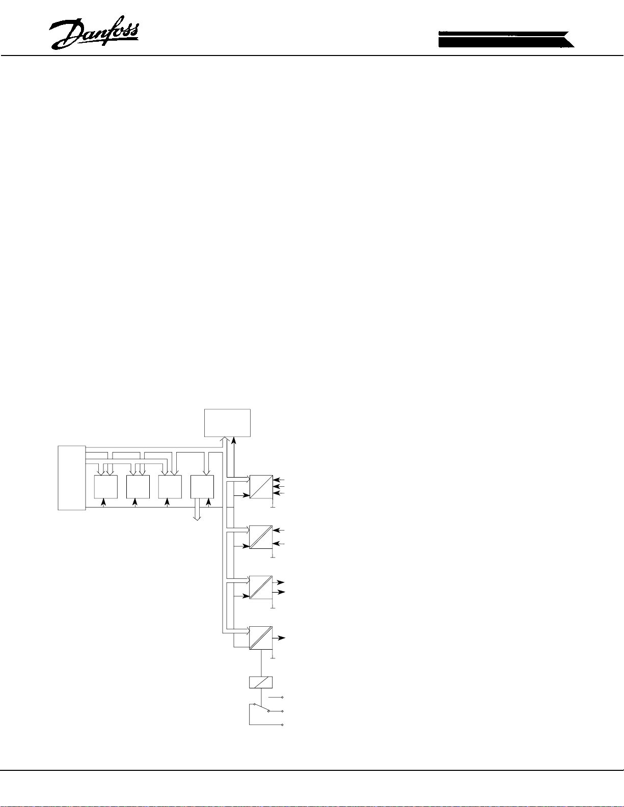
Refer to the overall schematic in the Appendix.
It is not the intention of this manual to enter into a detailed description
of the unit's operation. Moreover, it is intended to provide the reader
with a general view of the unit's main assemblies. With this information,
the repair technician should have a better understanding of the unit's
operation and therefore aid in the troubleshooting process.
The VLT is divided primarily into three sections commonly referred to
as: logic, power, and interface.
The control card itself primarily makes up the logic section. The heart
of the control card is a microprocessor which controls and supervises
all functions of the unit's operation. In addition, a separate PROM
contains the parameter sets which characterize the unit and provide
the user with the definable data enabling the unit to be adjusted to
meet the customer's specific application. This definable data is then
stored in an EEPROM which provides security during power-down and
also allows flexibility for future changes as needed. A custom integrated
circuit generates the PWM waveform which is then sent on to the
interface board for distribution to the individual gate drive circuits.
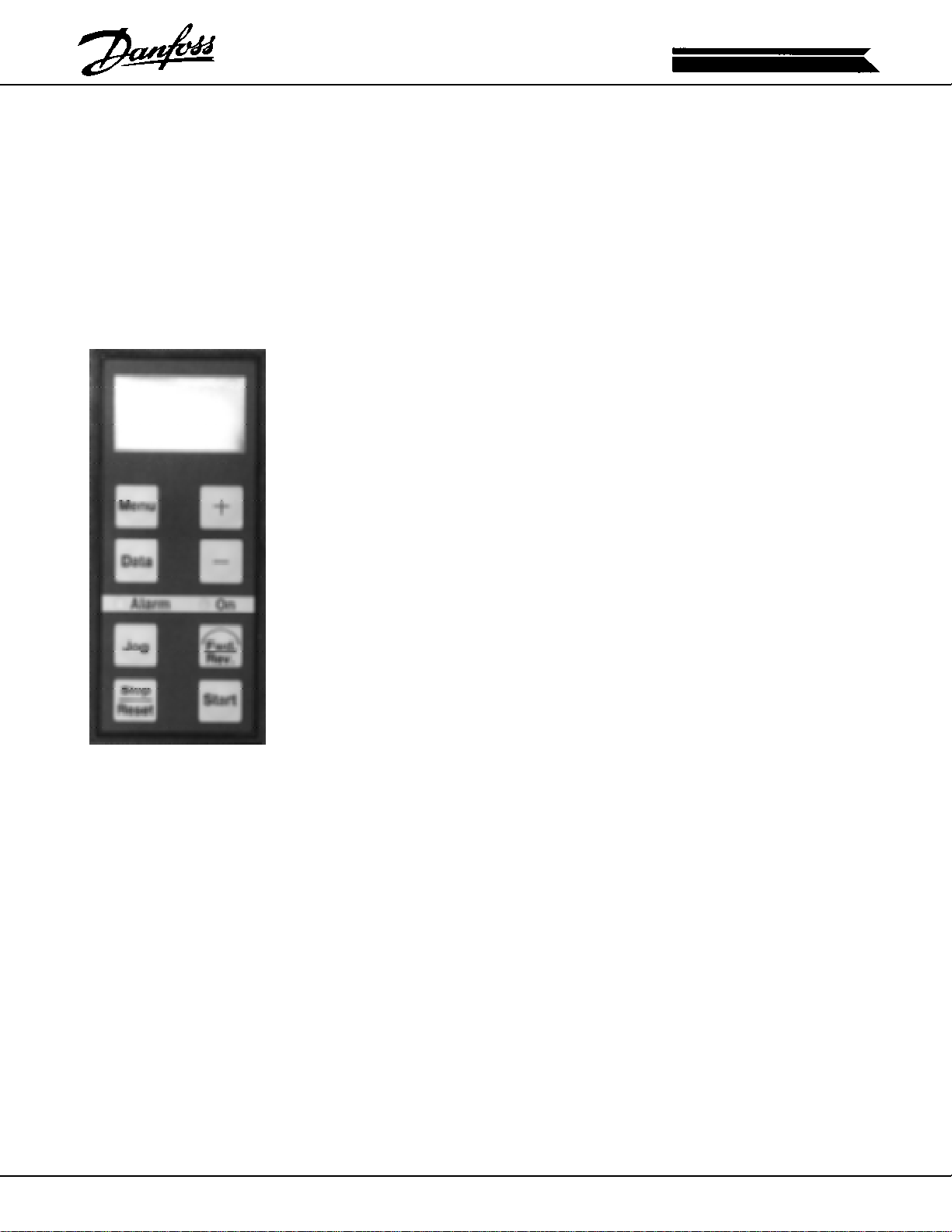
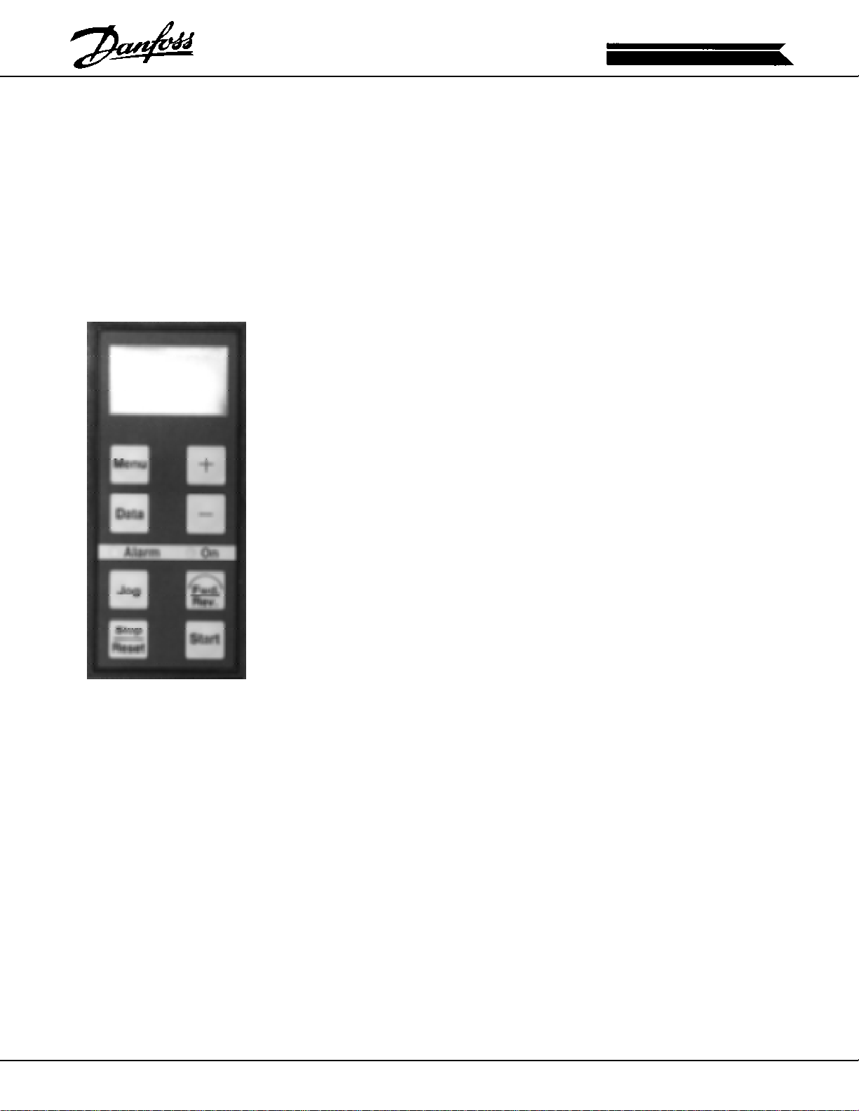
Also, part of the logic section is the keyboard/display
mounted on the control card. The keyboard provides
the interface between the digital logic and the human
programmer. The LCD (Liquid Crystal Display)
provides the operator/programmer with menu
selection, unit status and fault diagnostic information.
Programming is accomplished through the use of four
D
A
POWER
FEEDBACK
2
1
ANALOG
INPUTS
DIGITAL
INPUTS
of the eight keys available on the keyboard. The
additional four keys provide Local Start, Stop, Forward/
Reverse and Jog.
A series of customer terminals are provided for the
input of remote commands such as: Run, Stop and
Speed Reference. Terminals are also provided to
supply outputs to peripheral devices for the purpose
of monitoring and control. Two programmable relay
D
ANALOG
OUTPUTS
A
1
outputs are also available to interface the unit with other
devices.
In addition, the control card is capable of
DIGITAL
CHANNEL
1
communicating via a serial link with outside devices
such as a personal computer or a programmable logic
controller.
RELAY
The control card provides two voltages for use from
the customer terminal strip. The 24VDC is used
primarily to control functions such as: Start, Stop and
Forward/Reverse. The 24VDC is provided from a
separate section of the unit's power supply and is
delivered to the control card from the interface board
via the two conductor ribbon cable.
5
Page 6

LOGIC SECTION
(continued)
A 10VDC supply is also available for use as a speed reference when
connected to an appropriate potentiometer. These two voltage
references are limited in the amount of available current they can provide
(see specifications in Instruction Manual). Attempting to power devices
which draw currents in excess of that available may result in an eventual
failure of the power supply. In addition, if the supply is loaded too
heavily, sufficient voltage will not be available to activate the control
inputs.
During the troubleshooting process it is important to remember that the
control card can only carry out instructions as it has been commanded.
Of course, it is possible that as a result of a failure the control card may
fail to respond to commands. For this reason lies the necessity to
isolate the fault to the control commands, the control program or the
control card itself. If, for example, the unit does not run, but yet an
obvious reason is not apparent, check for proper control signals. Has
a run command been provided on the correct terminal; and if so, has
that terminal been designated as such in the programming of the control
card. In addition, be sure to verify that commands are being received
by testing for the presence of voltage on the appropriate terminals.
Never assume the signal is present because it is suppose to be. If
ever in doubt of whether the remote controls are functioning properly , it
is possible to take local control of the unit to verify if the control card is
operational. A word of caution here: prior to taking local control, insure
all other equipment associated with the drive is prepared to operate.
In many cases, safety interlocks are installed which can only be activated
through the use of a normal remote control start. In the same sense
that the control card can only respond to commands, comes the situation
that the control card makes a response without the presence of an
actual command. By the term response, it is not meant to infer that the
control card initiates such actions as Run or Stop, but rather suggests
that the control card displays unknown data or its performance is affected
as in what might be speed instability. In these cases, the first instinct
may be to replace the control card; however, in most instances, this
type of erroneous operation is usually due to electrical noise being
injected onto the remote control signal wiring. Although the control
card has been designed to reject such interference, noise levels of
sufficient amplitude can, in fact, affect the performance of the control
card.
As mentioned, sufficient levels of electrical noise can cause such things
as speed fluctuations as a result of interference with the speed reference
or with the operation of the microprocessor. In these situations it is
necessary to investigate the wiring practices of the installation. For
example, are the control signal wires running in parallel with other higher
voltage signals such as the input or output power wiring? As wires are
passed in close proximity to one another, voltages are induced through
capacitive or inductive coupling. This type of problem can be corrected
by rerouting the wiring or through the use of shielded cable. When
employing the use of shielded cable, it is important to properly terminate
the drain wire. The drain wire is terminated only at the control card end
of the wire. Specific terminals are designated for this purpose. The
opposite end of the shielded cable drain wire is then cut back and
taped off to prevent it from coming in contact with ground or acting as
an antenna.
6
Page 7

LOGIC TO POWER
INTERFACE
The logic to power interface isolates the high voltage components of
the power section from the low voltage signals of the logic. This is
accomplished by use of the interface board. All communication between
the control logic and the rest of the unit passes through the interface
board. This communication includes: feedback from the current sensors,
input from the heatsink temperature sensor, line voltage monitoring,
DC Bus voltage monitoring, control of the fans , control of the input
thyristor rectifiers and control of the gate drive firing signals. Also on
the interface board is the power supply which provides the unit with
low voltage power such as 24VDC, 16VDC, 13VDC and 5VDC. The
power supply is a Switch Mode Power Supply (SMPS). The switch
mode type supply is used due to its efficiency and linearity. Another
benefit of the switch mode supply is that it obtains its power from the
DC Bus; in the event of a power loss the power supply remains active
for a longer period of time versus conventional power supplies.
During the troubleshooting process it is important to determine whether
the interface board is receiving or sending the signal that appears to
be at fault. For example, the loss of a gate-drive signal is a waveform
generated by the interface board and conversely a heatsink overtemperature fault is a result of the interface board receiving an input
from the heatsink temperature sensor . If the signal is of the later type
(received), it is then necessary to isolate the fault to either the sending
device or the interface board. It is generally assumed that a component
within the unit is usually at fault; and although this may in fact be the
case, it is critical to check all possibilities to avoid costly errors and
lengthy downtime. In any case, the interface board is a relatively quick
and easy assembly to exchange; and so if it is suspect, a quick exchange
will prove the assumption.
7
Page 8
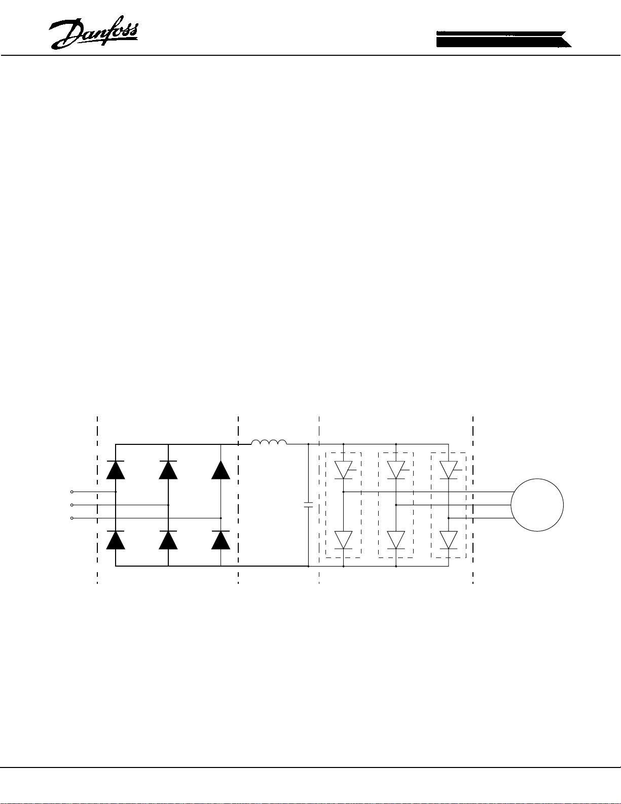
POWER SECTION
The power section is made up of the SCR/Diode modules (input
rectifiers), the soft charge circuit, the DC capacitor bank, the gate drive
and snubber cards and the IGBT power devices. Also located in the
power section are the DC Bus coil, the motor coils and, although not
typically considered part of the power section, the output phase current
sensors.
During the troubleshooting process, extreme care is required when
probing into the power section components. The DC Bus, when fully
charged, can be as high as 350VDC. Although this voltage begins to
decrease upon the removal of input power , it takes up to approximately
fifteen minutes to fully discharge the DC capacitor bank. Located on
the interface board is the Bus Charged Indicator. The red LED is visible
through the shield covering the lower portion of the interface board;
and as long as it is lit it indicates the DC Bus voltage is greater than
50VDC. A fault in the power section will usually result in at least one of
the incoming line fuses being blown. If one or more line fuses have
blown, it is not recommended to replace them and reapply power without
further investigation. In a case such as this, it would be suggested to
conduct the tests listed under Static Test Procedures in Section Three.
These tests will result in a thorough check of all the components
operating in the power section. In addition, following the identification
and replacement of power section components, it is recommended to
disconnect the motor wires prior to reapplying power . This precaution
opens the path for short circuit currents through the motor in the case
that all faulty components have not been replaced.
DC BUSRECTIFIER
R
S
T
SIMPLFIED PWM POWER SECTION
INVERTER
M
3Ø
8
Page 9

SEQUENCE OF
OPERATION
When input power is first applied, the SCR/Diode modules (input
rectifiers) are not gated so the incoming line voltage is rectified by the
soft charge rectifier (BR1). As the DC Bus capacitors charge, the inrush
current is limited by the series soft charge resistors (R2 and R3).
Following a time delay of approximately one second, the interface board
monitors the DC Bus voltage and, providing it has reached an acceptable
level, begins sending gate pulses to the SCR/Diode Modules. Once
the SCR's have been gated on, they remain in this state and the SCR/
Diode modules act as a normal rectifier. This scenario will only be
interrupted if the DC Bus fails to charge. This can be caused by
insufficient line voltage, a fault in the Power Section, a fault in the soft
charge circuit, and also by an open connection at PINS 1 and 2 of
MK15. The SCR Disable input at MK15 is provided as a means to
disable the SCR/Diode modules in the case of an external failure such
as in the Dynamic Brake option. Note that although the SCR/Diode
modules may be disabled, line voltage is still applied to the unit through
the soft charge circuit.
Providing the charging process proceeds normally , the power supplies
will come up and provide the control card and all other sections of the
unit with low voltage control power. At this time the display in the
control card will indicate the unit is ready for operation.
Following a run command and a speed reference, the control card
delivers the PWM signals (one for each phase) to the interface board.
The interface board in turn receives these three signals and creates
the six individual gate drive pulses. The gate drive pulses are sent to
the respective gate drive circuits located on the gate drive card. From
here the output power devices (IGBTS) are switched on and off to
develop the PWM waveform which is ultimately delivered to the motor .
As the unit operates, the interface board monitors the status of the
units operating condition. Currents in excess of limits, temperatures
being exceeded, and voltages out of specification will result in the
interface board responding with a fault and sending the appropriate
fault message to the control card. When a fault occurs, the interface
board will indicate the condition via a series of LED's. The control card
will also display a fault message, and in virtually all cases trip the unit
off line. Section 2 of this manual describes the fault LED's and
messages and provides direction in determining the cause and the
solution for the fault condition.
9
Page 10
SECTION TWO
FAULT INDICATORS
AND MESSAGES
A variety of messages are displayed by the control card. Some of
these indicate the operational status of the unit while others provide
warnings of an impending fault. In addition, there are the alarm
messages which indicate that the unit's operation has stopped due to
a fault condition. In this section we will deal with only those messages
which interrupt the unit's operation. A complete list of status messages
can be found in the Instruction Manual. Along with the control card
message, the interface board contains several Light Emitting Diodes
(LED's) which aid in the identification of the fault condition.
STATUS MESSAGES
CURRENT LIMIT
This message will flash in the display when the unit is operating above
the current limit setting as recorded in parameter 209. Parameter 310
may be set to provide a fixed time delay after which the unit will trip.
REF FAULT
This message will flash in the display should any live zero signal be
operating outside of its range. For example, 4-20ma has been selected
as the speed reference. Should the current loop be broken, the display
will flash "REF FAULT". Parameters 414 and 415 may be used to
select the unit's response to this condition.
NO 24 VOLT
This message will flash if the 24 volt power supply is missing or out of
tolerance. The 24 volt supply is used only for the customer's remote
connections.
NO MOTOR
This message will flash if Motor Check has been activated in parameter
313, terminal 27 is enabled and no motor is detected.
11
Page 11

WARNING MESSAGES
VOLTAGE LOW
This message will flash when the DC Bus voltage has fallen below the
lower limit. This is an indication of low line voltage. This is only a
warning message, however. If the condition persists, it will result in a
unit trip on "Under Voltage".
VOLTAGE HIGH
This message will flash when the DC Bus voltage has exceeded the
upper limit. This is an indication of high line voltage or regenerative
energy being returned to the bus. This is only a warning message,
however. If the condition persists, it will result in a unit trip on "Over
Voltage".
INVERT TIME
This message will flash when the inverter ETR value has reached 98%.
The inverter ETR begins counting up as soon as the output current
exceeds 105% of the unit's continuous current rating. At an inverter
ETR value of 100%, the unit trips on "Invert Time".
MOTOR TIME
This message will flash if Motor Thermal Protection has been activated
in parameter 315 and the motor ETR value has reached 98%. The
motor ETR value begins counting up if the motor is run at slow speed
or if the motor is consuming more than 116% of the motor's nominal
rated current as entered in parameter 107. At a motor ETR value of
100%, the unit will respond based on the setting in parameter 315. If
Trip has been selected, the unit will trip on "Motor Time".
OVERCURRENT
This message indicates at least one of the three output phases has
reached the peak current rating. In addition, the "Overcurrent" LED
(D8) on the interface board will flicker. During this time the control card
is attempting to initiate current limit. If the current rises to fast or the
control card cannot control the condition by means of current limit, the
unit will trip on "Over Current".
12
Page 12
ALARM MESSAGES
Alarm messages will be indicated by the following messages appearing
in the display and the red alarm LED being lit on the control panel. All
alarm messages result in the unit's operation being interrupted and
require a Manual or Automatic reset. Automatic reset can be selected
in parameters 309 and 312. In addition, the message "Trip" or "Trip
Locked" will be displayed. If "Trip Locked" is displayed, the only possible
reset is to cycle power and then perform a manual reset. Manual reset
is accomplished by means of the front panel push button or by a remote
contact closure on the appropriate control terminal. Remedies listed
with each alarm message give a basic description of the corrective
action which can be taken to correct the fault condition. For a more
detailed explanation, see the Sympton/Cause section beginning on page
21 and the application section on page 35. Also note the numbers in
parenthesis by each alarm message. These are the codes which will
appear in the Fault memory , Parameter 602. See APPENDIX I for more
on the Fault memory.
INVERTER FAULT (1)
This message indicates a fault in the power section of the unit. This
message may also be displayed if the unit has detected a phase loss
on the input. If a phase loss has been detected, the "Loss of Phase"
LED (D9) on the interface board will be illuminated and the "Inverter
OK" LED (D4) on the interface board will be out. This fault returns a
"Trip Locked". Also see Testing The Inverter Section, page 26.
OVER VOLTAGE (2)
This message indicates the DC Bus voltage upper limit has been
exceeded. In addition, the "High Bus Voltage" LED (D5) on the interface
board will be illuminated and the "Inverter OK" LED (D4) on the interface
board will be out. This fault can be caused by high line voltage or
regenerative energy being returned from the motor. To remedy this
fault condition, reduce the line voltage or extend the Decel Ramp. This
fault returns a "Trip". Also see Over Voltage Trips, page 38.
UNDER VOLTAGE (3)
This message indicates the DC bus voltage has fallen below the lower
limit. In addition, the "Low Bus Voltage" LED (D6) on the interface
board will be illuminated and the "Inverter OK" LED (D4) on the interface
board will be out. To remedy this fault, increase the line voltage to the
correct value for the unit rating. This fault returns a "Trip". Also see
Testing The Soft Charge Circuit, page 23.
OVER CURRENT (4)
This message indicates a short circuit on the output of the inverter.
This fault may also be caused by the unit reaching the peak current
rating too rapidly for the unit to respond with current limit. An example
may be closing an output contactor with the unit at speed and a high
inertia load. The "Overcurrent Trip" LED (D7) on the interface board
will be illuminated and the "Inverter OK" LED (D4) on the interface
board will be out. To remedy this fault, check the output wiring and
motor for short circuits. This fault returns a "Trip Locked". Also see
Over Current Trips, page 37.
13
Page 13

ALARM MESSAGES
(continued)
GROUND FAULT (5)
This message indicates a leakage to ground on the output of the inverter.
The "Ground Fault Trip" LED (D2) on the interface board will be
illuminated and the "Inverter OK" LED on the interface board will be
out. This fault will also be present if the programming card on the
interface board is not installed. To remedy this fault, check the output
wiring and motor for ground faults. This fault returns a "Trip Locked".
Also see Ground Fault Trips, page 37.
OVER TEMP (6)
This message indicates that the unit's heatsink temperature or the unit's
internal ambient temperature has exceeded permissible limits. This
fault may also be caused by a trip received from the optional external
temperature sensor if a sensor has been connected to terminal MK15
on the interface board. The interface board LED's indicate the nature
of the specific trip. In all cases below the "Inverter OK" LED will be out.
"Over Temperature Trip" LED (D3) only indicates the unit's heatsink
sensor has caused the trip. "Over Temperature Trip" LED (D3) and
Internal Over T emperature" LED (D109) illuminated indicates the thermal
sensor located on the interface board has detected high ambient
temperature within the unit and caused the trip. "Over Temperature
Trip" LED (D3) and "External Over Temperature" LED (D108) illuminated
indicates the external temperature sensor has caused the trip. To
remedy this fault, correct the over-temperature condition. This fault
returns a "Trip". Also see Overtemp Trips, page 39.
INVERT TIME (7)
This message indicates the unit has delivered greater than 105% of
the unit's continuous current rating for too long (inverse time function).
Prior to this fault condition the "Invert Time" warning will be displayed.
An indication from the interface board status LED's does not apply . To
remedy this fault, reduce the motor load to at or below the unit's
continuous current rating. This fault returns a "Trip Locked". During
the trip the counter will count down. Upon reaching 90%, the "Trip
Locked" will change to "Trip".
MOTOR TIME (8)
This message indicates the motor has consumed greater than 1 16% of
the motor's nominal current rating for too long as entered in parameter
107. This fault may also be caused from running the motor at a low
speed and high current for too long a period of time. This trip will only
occur if the "Motor Thermal Protection" has been activated in parameter
315. Prior to the trip the "Motor Time" warning will be displayed. In
addition, this fault may be displayed if an external thermistor has been
connected to input 16 and is defective, disconnected or indicating an
over-temperature condition. Also note that by selecting "Thermistor" in
parameter 400 in error will result in a "Motor Time" fault. An indication
from the interface board status LED's does not apply. To remedy this
fault, reduce the load on the motor or raise the motor's speed. This
fault returns a "Trip Locked". During the trip the counter will count
down. Upon reaching 0% the "Trip Locked" will change to "Trip".
14
Page 14

ALARM MESSAGES
(continued)
OC (D8-YELLOW)
OCT (D7-RED)
IOK (D4-GREEN)
LBV (D6-RED)
HBV (D5-RED)
GFT (D2-RED)
OTT (D3-RED)
PSF (D1-RED)
LOP (D9-RED)
IOT (D109-YELLOW)
EOT (D108-YELLOW)
CURRENT LIMIT (9)
This message will be displayed if the unit has run in current limit for a
time which exceeds the setting in parameter 310. To remedy this fault,
reduce the motor's load or verify that the correct settings have been
entered in parameter 209 (Current Limit) and parameter 310 (Current
Limit Trip Delay). This fault returns a "Trip". See Current Limit Trips,
page 35.
INTERFACE BOARD LED'S
HIGH BUS VOLTAGE
HBV (D5-RED)
Indicates the DC Bus voltage upper limit has been
exceeded.
The I0K LED will be off and the control card indicates
"Over Voltage".
INTERFACE BOARD LED'S
LOW BUS VOLTAGE
LBV (D6-RED)
Indicates the DC Bus voltage has fallen below the lower
limit.
The I0K LED will be off and the control card will indicate
"Under Voltage".
OVER CURRENT TRIP
OCT (D7-RED)
Indicates a short circuit on the inverter output.
The I0K LED will be off and the control card will indicate
"Over Current".
GROUND FAULT TRIP
GFT (D2-RED)
Indicates a Ground Fault on the Inverter Output.
The I0K LED will be off and the control card will indicate
"Ground Fault".
OVER TEMP TRIP
OTT (D3-RED)
Indicates the heatsink temperature is outside of the specified operating
range.
The I0K LED will be off and the control card will indicate "Over Temp".
INTERNAL OVER TEMP
IOT (D109-YELLOW)
Indicates the internal ambient temperature has been exceeded.
The I0K LED will be off and the control card will indicate "Over Temp".
15
Page 15

ALARM MESSAGES
(continued)
OC (D8-YELLOW)
OCT (D7-RED)
IOK (D4-GREEN)
LBV (D6-RED)
HBV (D5-RED)
GFT (D2-RED)
OTT (D3-RED)
PSF (D1-RED)
LOP (D9-RED)
IOT (D109-YELLOW)
EOT (D108-YELLOW)
EXTERNAL OVER TEMP
EOT (D108-YELLOW)
Indicates the external temperature sensor has detected an over temp
condition. If used, the sensor is connected to MK15 on the interface
board.
The I0K LED will be off and the control card will indicate "Over Temp".
POWER SUPPLY FAULT
PSF (D1-RED)
Indicates the low voltage power supplies are out of tolerance.
The I0K LED will be off.
LOSS OF PHASE FAULT
LOP (D9-RED)
Indicates one of the input phases is missing or
extremely low.
The I0K LED will be off and the control card will indicate
"Inverter Fault".
INTERFACE BOARD LED'S
OVERCURRENT
OC (D8)-YELLOW
Indicates the peak current of the inverter has been
exceeded.
INVERTER OK
IOK (D4) GREEN
Indicates the inverter is free of faults.
16
Page 16

GENERAL
TROUBLESHOOTING TIPS
Prior to diving into a repair here a few tips if followed will make the job
easier and may prevent unnecessary damage to good components.
1. First and foremost respect the voltages produced by the drive.
Always verify the presence of line voltage and bus voltage before
working on the unit. Also remember that some points in the drive
are referenced to the negative bus and are at bus potential even
though you may not expect it.
2. Never power up a unit which has had power removed and is
suspected of being faulty. If a short circuit exists within the unit
applying power is likely to result in further damage. The safe
approach is to conduct the Static Test Procedures starting on page
23. The static tests check all high voltage components for short
circuits. The tests are relatively simple to make and can save money
and downtime in the long run.
3. The safest method of conducting tests on the drive is with the motor
disconnected. In this way a faulty component that was overlooked
or the unfortunate slip of a test probe will generally result in a unit
trip instead of a component failure.
4. Following the replacement of parts test run the unit with the motor
disconnected. Start the unit at zero speed and slowly ramp the
speed up until the speed is at least above 40 Hz. Monitor the phase
to phase output voltage on all three motor terminals to check for
balance. If balanced the unit is ready to be tested on a motor. If
not, further investigation is necessary.
5. Never attempt to defeat fault protection devices within the drive.
This will only result in unwanted component damage and may
result in personal injury as well.
6. Always use factory approved replacement parts. The unit has been
designed to operate within certain specifications. Incorrect parts
may effect the tolerence and result in further damage to the unit.
7. Read the instruction and service manuals. A thorough
understanding of the unit is the best approach. If ever in doubt
consult the factory or an authorized repair center for assistance.
17
Page 17

1)
2)
Symptom
Motor runs unevenly
5)
Symptom
Motor does not run
Is the output phase to
phase voltage and current
balanced?
YES NO
4)
Verify correct settings have
been entered in Group 1
"Load & Motor"
Also see Section
"Applications" pg. 35
6)
Is the display illuminated?
NO YES
3)
See "Testing the Inverter"
Section page 26.
8)
Are fault messages shown
in the display?
7)
Is the correct mains supply
present at R, S, T?
YES
See: 9)
page 19
NO YES
See: 18)
page 20
Refer to the section Alarm
Messages page 13.
18
Page 18

9)
10)
Symptom
No fault report or light in
display.
Have prefuses for the VLT
adjustable frequency drive
blown, F1, F2, F3 or F4,
F5, 56?
NO YES
12)
Disconnect all control
signal wires on the control
card.
Does that remove the
fault?
NO YES
14)
Is the DC Bus voltage OK?
Measure the DC Bus
voltage between terminals
(89) +VDC and (88) –VDC.
11)
If one or more of the fuses
F1, F2 or F3 have blown,
test the input rectifiers and
the inverter section, pages
25 and 26. If one or more
of the fuses F4, F5 or F6
have blown test the soft
charge circuit, page 23.
13)
The fault may be caused
by a short circuit in the
control signals.
Check control wiring for
proper connection.
YES NO
16)
Replace the Control Card,
see page 31. Does the
problem disappear?
YES NO
Resume
operation
15)
Test the Soft Charge
Circuit and input rectifier,
pages 23-25.
17)
Replace the Interface/ILD
card, see page 30. Does
the fault disappear?
YES NO
Consult
Resume
operation
factory
19
Page 19

18)
19)
21)
Symptom
Motor stopped. Light in
display, but no fault report.
Start the VLT adjustable
frequency drive by
pressing "Start" on the
control panel.
20)
Has the display locked, i.e.
it cannot be changed or is
illegible?
NO YES
22)
Has the motor been
correctly connected and
are all motor phases in
order?
YES NO
Replace the Control Card,
see page 31. If this does
not help, the fault might be
electrical noise. Check
whether the following
precautions have been
taken:
• Have shielded cables
been used?
• Are the shields correctly
terminated?
• Is the unit properly
grounded to earth?
Correct the motor wiring
Insure motor overloads are
seset and output contactor
closed.
CAUTION:
Prior to running in Local,
insure all other
equipment associated
with the VLT is ready to
function or has been
isolated
23)
Attempt to run the VLT in
local.
SEE CAUTION at LEFT
Make the following
parameter settings:
Parameter 003 = Local
Parameter 004 = Fref.
Change by means of
+ and – keys.
Does the motor run?
YES NO
24)
Verify that the control
signals are connected to
the correct terminals and
the appropriate parameter
settings have been
entered.
25)
Replace the Control card,
see page 31.
Does the motor run?
NO
26)
Replace the Interface/ILD
card, see page 31.
Does the motor run?
NO
Consult
factory
20
Page 20

SYMPTOM/CAUSE CHARTS
SYMPTOM/CAUSE charts are generally directed towards the more experienced technician. The intent of these
charts is to provide a range of possible causes for a specific symptom. In doing so, these charts provide a direction,
but with limited instruction.
SYMPTOM POSSIBLE CAUSES
1. Control Card Display Is Not Lit.
2. Blown Input Line Fuses
3. Blown Soft Charge Fuses
Incorrect or missing input voltage
Incorrect or missing DC bus voltage
Remote control wiring loading the power supply
Defective Control Card
Defective Interface Board
Defective or disconnected ribbon cables
Shorted SCR/Diode module
Shorted IGBT
Shorted soft charge rectifier
Shorted DC bus
Shorted brake IGBT
Mis-wired Dynamic Brake option
4. Motor Operation Unstable (Speed
Fluctuating)
5. Motor Draws High Current But
Cannot Start. (May appear to rock
back and forth.)
6. Motor Runs Unloaded But Stalls
When Loaded. (Motor may run rough
and VLT may trip.)
Start compensation set too high
Slip Compensation set too high
Improper current feedback
PID Regulator or Auxilary Reference misadjusted
Open winding in motor
Open connection to motor
One inverter phase missing. Test output phase balance, page 27.
One half of one inverter phase missing. Test output phase balance,
page 27.
21
Page 21

SYMPTOM/CAUSE CHARTS
SYMPTOM/CAUSE charts are generally directed towards the more experienced technician. The intent of these
charts is to provide a range of possible causes for a specific symptom. In doing so, these charts provide a direction,
but with limited instruction.
SYMPTOM POSSIBLE CAUSES
7. Unbalanced Input Phase Currents
Note: Slight variations in phase
currents is normal. Variations greater
than 5% require investigation.
8. Unbalanced Motor Phase Currents
Note: Slight variations in phase
currents is normal. Variations greater
than 5% require investigation.
Input line voltage unbalanced
Faulty connection on input wiring
Fault in plant power transformer
Input SCR/Diode module faulty or not being gated.
Open motor winding
Faulty motor connection
Fault in inverter section (see Symptom No. 6.)
22
Page 22

SECTION THREE
STATIC TEST
PROCEDURES
All tests will be made with an ohmmeter capable of testing diodes. Use
a digital VOM set on diode scale or an analog ohm meter set on RX100
scale. Before making any checks disconnect all input power, motor
and brake option connections.
CAUTION: Allow sufficient time for the DC Bus to fully discharge
before beginning testing. The presence of bus voltage can be
tested by setting your voltmeter for 500VDC and reading the
terminals labeled 88 (–) and 89 (+).
TESTING THE
SOFT CHARGE CIRCUIT
The purpose of statically testing the soft charge circuit is to rule out
failures of the Soft Charge Rectifier and Soft Charge Resistors. If the
soft charge fuses have blown, it indicates the possibility of a short circuit
of the DC Bus. A DC Bus short can be caused by:
Two shorted IGBT's--one negative and one positive in
the same phase
A shorted Brake Module IGBT or having connected the
Brake Module incorrectly
Shorted DC Bus capacitors
These are the primary causes; however, any component which is
connected across the positive and negative bus if shorted can result in
a DC Bus short. Conducting the remaining Static Test Procedures
should rule out the remaining possibilities.
23
Page 23

TESTING THE
SOFT CHARGE CIRCUIT
1. Prior to making the test, it is necessary to verify that the three soft
charge fuses (F4, F5, and F6) are good. If they are not, they must be
replaced before proceeding.
2. Remove the plug on spade connectors from the plus and minus
terminals of the rectifier bridge (BR1).
3. Connect the positive (+) meter lead to the positive terminal of the
rectifier. Connect the negative (–) meter lead to the soft charge fuses
(F4, F5, and F6) in turn. Each reading should show open.
4. Reverse the meter leads connecting the
(–) lead to the positive terminal of the rectifier
and the (+) lead to the soft charge fuses (F4,
F5, and F6) in turn. Each reading should show
a diode drop.
5. Connect the positive (+) meter lead to the
negative terminal of the rectifier. Connect the
negative (–) meter lead to the soft charge fuses
(F4, F5, F6) in turn. Each reading should show
a diode drop.
6. Reverse the meter leads connecting the
(–) lead to the negative terminal of the
rectifier and the (+) lead to the soft charge
fuses (F4, F5, and F6) in turn. Each reading
should show open.
(SHOWN WITH CONTROL/INTERFACE
CARD CARRIER REMOVED)
7. Set the meter on the lowest resistance
scale. Connect the positive (+) meter lead to
the wire previously removed from the positive
terminal of the rectifier. Connect the negative
(–) meter lead to the positive bus rail on the
input rectifiers. The positive bus rail is the lower
bus bar. The series soft charge resistors (R2
and R3) should read twenty (20) ohms plus or
minus two (2) ohms.
8. Reconnect the wires to the plus and minus
terminals of the bridge rectifier (BR1). Test is
complete.
NOTE: Finding a shorted Soft Charge Rectifier and/or open Soft Charge
Resistor may indicate a short circuit on the DC bus. Continue with the
remaining static test procedures prior to applying power.
24
Page 24

TESTING THE
INPUT RECTIFIERS
The purpose of statically testing the input rectifiers is to rule out failures in these devices. Typically a
failure of an input rectifier will have caused the input line fuses to blow. It should also be noted that
blown input line fuses can also be a result of a shorted IGBT. Testing the inverter section as described
on page 26 will rule out short circuits in the IGBT's.
1. Prior to making the test, it is necessary to verify that the three
input fuses (F1, F2, and F3) are good. If they are not, they must
be replaced before proceeding.
2. Connect the positive (+) meter lead to terminal 89 (+VDC).
Connect the negative (–) meter lead to terminals 91 (R), 92 (S),
and 93 (T) in turn. Each reading should show open.
3. Reverse the meter leads connecting the (–) lead to terminal 89
96 97 98
89 88
(+VDC) and the (+) lead to terminals 91 (R), 92 (S), and 93 (T) in
turn. Each reading should show a diode drop.
AC LINE AND MOTOR WIRING
4. Connect the positive (+) meter lead to terminal 88 (–VDC).
Connect the negative (–) meter lead to terminals 91 (R), 92 (S),
and 93 (T) in turn. Each reading should show a diode drop.
5. Reverse the meter leads connecting the (–) lead to terminal 88
(–VDC) and the (+) lead to terminals 91 (R), 92 (S), and 93 (T) in
turn. Each reading should show open. Test is complete.
Incorrect readings indicate a faulty Input Rectifier . The rectifier at fault
can be identified by noting which terminal read incorrectly . Terminal 91
corresponds to U4, Terminal 92 to U5 and Terminal 93 to U6. The
modules are arranged in the unit from left to right, U4, U5, U6. See
Removal and Replacement Instructions on page 33.
25
Page 25

TESTING THE
INVERTER SECTION
The purpose of statically testing the inverter section is to rule out failures of the IGBT power devices
and the snubber diodes. If a short circuit is discovered during the testing, the particular devices can
be pinpointed by noting the output terminal indicating the short circuit. The output terminals are
designated with a letter corresponding to the phase that feeds that terminal. When looking in the unit,
the "U" phase is on the top, "V" phase in the middle and the "W" phase on the bottom. In each phase
the negative half of the phase in on the right and the positive half is on the left.
1. Prior to making the test, it is necessary to disconnect the motor
leads from the unit. By not doing so, the low resistance windings
of the motor will make a short circuit on one terminal also appear
on the other terminals.
96 97 98 89 88
AC LINE AND MOTOR WIRING
SNUBBER DIODES D1 - D6
Anode (+)
D6
Cathode (–)
D5
2. Connect the positive (+) meter lead to terminal 89 (+VDC).
Connect the negative (–) meter lead to terminals 96 (U), 97 (V),
and 98 (W) in turn. Each reading should show open.
3. Reverse the meter leads connecting the (–) lead to terminal 89
(+VDC) and the (+) meter lead to terminals 96 (U), 97 (V), and
98 (W) in turn. Each reading should show a diode drop.
4. Connect the positive (+) meter lead to terminal 88 (–VDC).
Connect the negative (–) meter lead to terminals 96 (U), 97 (V),
and 98 (W) in turn. Each reading should show a diode drop.
5. Reverse the meter leads connecting the (–) lead to terminal 88
(–VDC) and the (+) meter lead to terminals 96 (U), 97 (V), and 98
(W) in turn. Each reading should show open. Test is complete.
Incorrect readings indicate a faulty IGBT and/or Snubber Diode. To
further identify the faulty component the IGBT Snubber Board must be
removed. The Snubber Diodes on the IGBT Snubber Board and the
IGBT's can then be tested individually. See Removing and Replacing
Gate Card and IGBT on page 32.
Once the IGBT Snubber Board is removed the Inverter Section can be
retested, using the same tests as above, to verify the condition of the
IGBT's.
Testing Snubber Diodes
D4
Anode (+) and the negative (–) meter lead to the Cathode (–) of each
diode. Each reading should show a diode drop.
To test the Snubber Diodes connect the positive (+) meter lead to the
D3
Reverse the meter leads connecting, the (–) lead to the Anode (+) and
the (+) meter lead to the Cathode (–) of each diode. Each reading
should show open.
D2
Incorrect readings indicate a faulty Snubber Diode. Replace the Snubber
Board.
D1
26
Page 26

TESTING THE HEATSINK
TEMPERATURE SENSOR
The heatsink temperature sensor is a NTC (negative temperature
coefficient) resistor rated for 10K ohm at 25°C. As the temperature
rises, the resistance decreases. Conversely , as the temperature falls,
the resistance increases. The interface board monitors this resistance
and initiates a fault when the resistance is less than 787 ohms. This
corresponds to a heatsink temperature of approximately 95°C. By
unplugging connector MK16 on the interface board, the resistance of
the sensor may be read.
The sensors' resistance must be between 787 ohms - 105 K ohms to
be free of a fault condition.
In the case of an open reading or very high resistance, the connections
between the plug and the sensor should also be checked.
DYNAMIC TEST PROCEDURES
TESTING FOR OUTPUT PHASE
IMBALANCE
When testing phase imbalances, it is practical to measure both voltage
and current. A balanced voltage reading, but unbalanced current,
indicates the motor is drawing uneven current. This could be caused
by a fault in the motor windings or in the wiring connections between
the drive and motor. When both voltage and current are unbalanced,
it indicates a switching problem or a faulty connection within the unit
itself. This can be caused by improper gate drive signals as a result of
a faulty interface board or gate drive board. A faulty IGBT or loose
wire connection between the IGBT and the output terminals may also
be the cause.
CAUTION: Allow sufficient time for the DC Bus to fully discharge
before beginning testing. The presence of bus voltage can be
tested by setting your voltmeter for 500VDC and reading the
terminals labeled 88 (–) and 89 (+).
NOTE: When monitoring output voltage an analog voltmeter should
be used. Digital meters are sensitive to the switching frequency and
usually read erroneously.
1. Remove the motor leads from the output terminals of the unit.
2. Conduct the Inverter Test Procedure in Section Three on page
26.
3. If the Inverter Test Procedure proves good, power the unit back
up. Initiate a Run command with a speed reference greater than
40Hz.
4. Read the phase-to-phase output voltage. The actual value of the
readings is of less importance than the phase-to-phase balance.
This balance should be within 8 volts per phase.
5. If a greater-than-8-volt imbalance exists, measure the gate drive
firing signals. See page 28.
6. If the phase-to-phase output voltage is balanced, recheck motor
and connections for faults. Consult the factory for additional
assistance.
27
Page 27

TESTING GATE DRIVE
FIRING CIRCUITS
CAUTION: The gate firing signals are referenced to the negative DC Bus and are therefore at Bus
potential. Extreme care must be taken to prevent personal injury or damage to equipment. Oscilloscopes, when used, should be equipped with isolation devices.
The individual gate drive firing pulses originate on the interface board.
These pulses leave from connector MK1 and are distributed to each
phase via the Gate Drive Board. An oscilloscope is the instrument of
choice when observing waveforms; however, when a scope is not
available, a simple test can be made with a DC voltmeter . When using
a voltmeter, compare all the gate pulses to one another. A missing
gate pulse will show no reading and an incorrect gate pulse will generally
read more or less than the others. At very low frequencies (below
10Hz) the voltmeter will tend to bounce around as the pulse rises and
falls. Above 10Hz the voltmeter will remain stable. When testing with
an oscilloscope, the test points are the same. This test can be made at
the interface board or at each gate card output to its respective IGBT.
These tests can be made with or without a motor. However, it is
generally safer to have the motor disconnected.
GATE DRIVE SIGNAL AT
INTERFACE BOARD MK1
5V/DIV DRIVE IN RUN AT 10HZ
100uSEC/DIV
TESTING AT THE INTERFACE BOARD
Use an oscilloscope or an analog or digital DC
voltmeter set for 10VDC. Connect the negative (-)
meter lead or scope ground to pin 1 of connector MK1
of the interface board. With the positive (+) meter lead
or scope probe compare the readings of pins 13, 14,
17, 18, 21 and 22 of connector MK1. Remember,
with the voltmeter the running speed of the VLT must
be above 10Hz. A voltmeter will read an average
voltage of 2.3VDC and the scope will exhibit a
waveform similar to that shown to the left. If any of the
readings appear incorrect, replace the interface board.
Test again since the gate card may be loading the
source and pulling down the signal. If replacement of
the interface board does not correct the problem,
replace the respective gate card.
Pins 21 and 22 feed the "U" phase.
Pins 17 and 18 feed the "V" phase.
Pins 13 and 14 feed the "W" phase.
28
Page 28

TESTING A T THE
GATE CARD OUTPUT
CAUTION: Allow sufficient time for the DC Bus to fully discharge
before beginning testing. The presence of bus voltage can be
tested by setting your voltmeter for 500VDC and reading the
terminals labeled 88 (–) and 89 (+).
Never power up the unit with any of the IGBT gate leads
disconnected from the Gate Drive Card. A disconnected gate lead
will cause the IGBT to switch on and result in its failure.
T esting the gate drive firing pulses at the output of the gate card insures
the signal has successfully made it to that point removing suspicion
from the interface board and the gate card. Testing in this area also
requires a greater deal of caution since the working space is tighter
and high voltages are in close proximity.
Unlike similar models of the VL T , the control card/interface board carrier
does not tilt down. It must be completely removed in order to gain access
to the Gate Drive Card. As this is the case, testing at the gate driver
requires that the test leads are connected and then the unit is
reassembled to conduct the tests. Extreme care must be taken to insure
test leads can not come in contact with other points of the card when
reinstalling the control card/interface board carrier.
If any of the readings as observed below appear
incorrect, replace the gate card. Prior to doing so,
insure the signals have also been tested at the
interface board to verify they are correct. If
replacement of the gate card does not correct the
problem, the IGBT(s) in that phase may be the cause.
IGBT GATE DRIVER SIGNAL
AT GATE CARD OUTPUT
10V/DIV 100uSEC/DIV
Use an oscilloscope or an analog or digital DC
voltmeter set for 10VDC. Connect the negative (–)
meter lead or scope ground to pin 2 of connector MK2
of the gate card. Connect the positive (+) meter lead
or scope probe to pin 1 of connector MK2. Remember,
with the voltmeter the running speed of the VLT must
be above 10Hz. A voltmeter will read an average
voltage of approximately 2.2VDC and the scope will
exhibit a waveform similar to that shown on the left.
Repeat the test on the remaining connectors MK3,
MK5, MK6, MK8 and MK9.
29
Page 29

TESTING INPUT RECTIFIERS
Theoretically , the input current drawn on each of the three input phases
should be equal. These currents will vary, however, due to variations
in phase-to-phase input voltage and due to some single phase loads
within the drive.
Given that the input phase voltages are equal, the input currents phaseto-phase should not vary more than 5%. Current imbalances in excess
of 5% may indicate one of the SCR/diode modules is not conducting
properly. When the VLT is lightly loaded, it may not be possible to
detect a current imbalance. If suspect, the modules should be statically
tested. Refer to the Static Test procedures beginning on page 23.
TESTING FOR CURRENT
FEEDBACK
A current sensor is in line with each phase of the output. These hall
effect devices generate a current that is proportional to the current
being drawn in each respective phase. The VL T relies on this feedback
for proper waveform control and for providing fault protection.
A simple test of the signals can be made with an AC voltmeter. The
voltage level present is relative to the current signal generated. At very
light loads the voltage may be no more than 100 to 300 millivolts. The
importance of this test is to verify that all three sensors are functioning
and the signals are approximately equal when compared to each other .
With an AC voltmeter, connect the negative (-) meter lead to pin 3 of
connector MK15 on the interface board. With the positive (+) meter
lead compare the voltage readings at the right side of resistors R28,
R29, R30.
Severe imbalances in the readings indicates an uneven current draw
by the motor. See "Testing for Output Phase Imbalance" on page 27 if
a large imbalance exists.
30
Page 30

SECTION FOUR
REMOVING AND REPLACING
THE CONTROL CARD
PRYING POINT
MK200
MK201
PRYING POINT
REMOVAL
1. Remove the two ribbon cables from plugs MK200 and
MK201.
2. Insert a screwdriver at the points indicated on the right
side of the control card cassette and pry upward.
3. Lift the control card out and set aside.
REPLACEMENT
1. Insert the left side of the control card into the guide slot of
the control card/interface board carrier.
2. Firmly press down on the right side of the control card
cassette until it snaps into place.
3. Reconnect the two ribbon cables to plugs MK200 and
MK201.
REMOVAL
1. Remove the control card to gain access to the interface
board.
2. Remove all plugs from the interface board.
are coded to insure they can be returned to the correct
location.
3. Working around the board, release the 11 swag clipswith
the use of needle-nose pliers. Gently lift the board clear of
the swags as you go.
4. If the interface board is being exchanged with another,
remove the Programming Module installed in socket MK4
from the existing board and install it in the replacement
board.
Note: All plugs
REMOVING AND REPLACING
THE INTERFACE BOARD
REPLACEMENT
1. To install, align the interface board over the swag clips and
gently but firmly press down on the board in the area of
each swag clip insuring the board snaps securely in place.
2. Reconnect all plugs.
3. Insure the programming module is installed in socket MK4
of the interface board.
4. Reinstall the control card.
31
Page 31

REMOVING AND REPLACING
GATE CARD, SNUBBER BOARD
AND IGBT
ESD Caution IGBT
Electro Static Discharge (ESD) can have
damaging effects on sensitive
components. The IGBT gate connection
is sensitive to static electricity . Whenever
the gate leads are disconnected from the
gate card or IGBT , the gate lead terminals
must be shorted together. This can be
accomplished with test leads or by
inserting small jumper wires in the ends
of the gate lead wire connectors.
1. To gain access to these assemblies remove the Control Card/
Interface Board Carrier. This is done by loosening the two captive
screws on the left side of the Carrier. Slide the carrier towards the
top of the unit and lift out. There is ample cable length to allow the
Carrier to rest in the bottom of the unit.
GATE DRIVE CARD
2. Remove plugs MK1 through MK9 from the gate drive card. Note:
Coded plugs and the wire harness arrangement insure all plugs
can be returned to the correct location.
3. Working around the board, release the eight swag clips with the
use of needle-nose pliers. Lift the board free of the swags as you
go.
Reverse the procedure to replace.
IGBT SNUBBER BOARD
4. Remove the nine Phillips screws securing the IGBT Snubber Board.
NOTE: This is a good time to statically test the Snubber Diodes.
See testing the Snubber Diodes on page 26.
Reverse the procedure to replace. T orque to 15-19 LB-IN (1.7-2.15
NM).
IGBT
5. Remove the three (3) Standoffs (13mm) securing the Bus Bar and
the Motor Coil Wire to the IGBT to be replaced.
6. Loosen the remaining Standoffs, but do not remove, on the
remaining two IGBT's. This should allow sufficient clearance to slide
the IGBT from beneath the Bus Bar.
7. Remove the two Phillips screws securing the IGBT to the heatsink.
Reverse the procedure to replace. Prior to installing the IGBT,
apply silicon grease 3 mils thick to the entire base of the module.
Transfer the gate wires from the replaced IGBT to the new IGBT
insuring correct polarity . Upper set (E2-NEG, G2-POS), lower set
(E1-NEG, G1-POS). Alternately torque the IGBT mounting screws
initially to 8-10 LB-IN (.90-1.13 NM), final torque to 22-26 LB-IN
(2.49-2.93 NM).
Replace the standoffs and insure all standoffs are torqued initially
to 8-10 LB-IN and finally torqued to 15-19 LB-IN (1.70-2.15 NM).
GATE DRIVE CARD
IGBT SNUBBER BOARD
32
IGBT'S
Page 32

REMOVING AND REPLACING
INPUT RECTIFIERS
To DC Coil
BL
WH
BL:WH
BL
WH
REMOVAL
1. Remove the line side Phillips screw from the rectifier to be replaced.
2. Remove the two Phillips screws from the bus bar connections of
the rectifier being replaced. Loosen but do not remove the remaining
bus bar screws on the other rectifiers.
3. Remove the two gate wire leads from the rectifier.
4. Remove the two Phillips screws securing the rectifier module to
the heatsink and slide the module from beneath the bus bars.
REPLACING
5. Prior to installing apply silicon grease 3 mils thick
to the entire base of the module.
6. Install the two Phillips screws securing the module
to the heatsink and torque initially to 22-26 LB-IN
(2.49-2.93 NM) then final torque to 44 LB-IN (5.00
NM).
o
Positive
BUS Bar
L1
7. Plug the gate wires into the gate lead connectors.
8. Install the Phillips screws securing the bus bars to
the rectifier. Torque these and the remaining bus
bar screws to 18-22 LB-IN (2.03-2.49 NM). Insure
the bus sensing wire marked "K" is secured to
the lower bus bar.
9. Install the Phillips screw securing the line
connection to the module. Torque to 18-22
LB-IN (2.03-2.49 NM). Insure the soft charge
jumper wires have been included. The three soft
L3
"K"
o
o
o
:
"T"
<
>
<
To
BUS
Capacitor
Negative
BUS Bar
:
o
o
o
"R"
Rectifer
Module
o
o
o
"S"
L2
charge jumper wires are labeled "R", "S" and "T"
and are connected in that order from left to right.
33
Page 33

SECTION FIVE
APPLICATIONS
CURRENT LIMIT TRIPS
UNSTABLE
MOTOR OPERATION
Excessive loading of the VLT may result in "CURRENT LIMIT" trips.
This is not a concern if the unit has been properly sized and intermittent
load conditions cause anticipated operation in current limit. Nuisance
current limiting and unstable motor operation can, however , be caused
by improperly setting specific parameters. The following parameters
are those which are most critical to the VLT/Motor relationship.
100 - Load Type
103 - Motor Power
104 - Motor Voltage
105 - Motor Frequency
107 - Motor Current
108 - Motor Magnetizing Current
109 - Start Voltage
110 - Start Compensation
209 - Current Limit
Parameter 100
An incorrect setting may provide an improper voltage to frequency ratio
to the motor with respect to the load demand. For example, a constant
torque (CT) load requires a higher V/F ratio at start-up than a variable
torque (VT) load. If a VT mode of operation has been selected when
operating a CT load, improper starting torque will be available.
Parameters 103, 104, 105, 107
These parameters, when incorrectly set, have an effect on other
parameters as well as the unit's interpretation of the load. In setting
these parameters enter the name plate data from the motor into the
appropriate parameter. Use the conversion chart to change from HP to
KW.
HP 1 2 3 5 7 10 15 20 30 40 50 60 75
kW 0.75 1.5 2.2 4.0 5.5 7.5 11 15 22 30 37 45 55
HP 100 125 150 200 250 300
kW 75 90 110 160 185 200
35
Page 34

Parameter 108
Motor Magnetization Current is the current required to maintain the
magnetic field in the motor. Magnetization Current is factory set based
on the motor power entered in parameter 103. This current value can
also be found by running the motor without anything connected to the
shaft and recording the current. Data charts in motor catalogs also
contain this information.
Parameter 109
Start voltage is factory set based on the motor power entered in
parameter 103. In most cases the factory setting is sufficient; however ,
a slight increase in start voltage may be required for high inertia loads.
High current at low speeds results in an increased voltage drop in the
motor and hence the need for additional start voltage.
If multiple motors are connected to a single unit, it is usually necessary
to increase the start voltage. Smaller motors have greater voltage
drops at low frequencies so additional start voltage is usually required.
It is also possible to have start voltage set too high and result in startup trouble. The best rule of thumb is to start at the factory setting and
make changes in small increments. Start and stop the unit to test the
results.
Parameter 110
Start compensation; In higher horsepower ranges the need for start
compensation is usually unnecessary. The factory setting is (0) zero.
Changes can be made, however, if the load/motor combination does
not require it, Instability or start-up difficulty will be the result.
Parameter 209
Current limit; Current limit is factory set based on the motor size and
voltage selected. Current limit settings which are too low may result in
difficulty starting or premature trips.
36
Page 35

"GROUND FAUL T" TRIPS
Trips occurring from ground faults are usually the result of short circuits
to earth ground either in the motor or the wiring to the motor. The VLT
detects ground faults by monitoring all three phases of output current
and looking for severe imbalances in those currents. When a "Ground
Fault" trip occurs it is necessary to measure the resistance of the motor
windings and wiring with respect to earth ground. The instrument
normally used for this purpose is a Megohmmeter or commonly referred
to as a "Megger". Many times these resistance readings are taken
with a common Ohmmeter, which is actually incapable of detecting
any shorts other than those that are virtually direct. A Megger has the
capability of supplying higher voltages, typically 500 volts or more, which
enables the Megger to detect breakdowns in insulation or higher
resistance shorts which cannot be picked up through the use of an
Ohmmeter. When making resistance measurements to ground, it is
necessary to disconnect the motor leads from the output of the VLT.
The measurements should then be taken at the point of connection to
the VLT so the motor and all associated wiring and connections are
captured in the test. When reading the results of the Megger test, the
rule of thumb is any reading less than 500 Megohms should be suspect.
Solid, dry wiring connections normally result in a reading of infinity.
Since the VL T monitors output current to detect ground faults, there is
also the possibility that the current sensors and/or the detection circuitry
in the VLT could also be the cause of a ground fault. Tests can be
made on this circuitry to isolate the possibilities. Refer to the Dynamic
Test procedures on "Testing for Current Feedback" page 30. Consult
the factory for additional assistance.
"OVERCURRENT" TRIPS
Trips due to "OVERCURRENT" can be caused by short circuits on the
output of the unit or by instantaneous high currents occurring so rapidly
that the unit cannot respond.
Short circuit trips are generally a result of a phase-to-phase short in
the motor windings or in the wiring between the unit and the motor.
Short circuit trips are easily diagnosed by removing the motor leads
from the unit and performing a phase-to-phase resistance test on the
motor leads. This resistance read in ohms will normally be quite low so
it is important to have the ohmmeter set on its lowest resistance scale
to avoid misinterpreting the readings observed.
37
Page 36

"OVERCURRENT" TRIPS
(CONTINUED)
Instantaneous overcurrent trips are caused by the current rising so fast
on the output that the unit cannot respond. One example of this situation
is in applications where the unit is running at speed and an output
contactor is closed between the unit and the motor. At the point the
contactor is closed, the motor is effectively seen as a short circuit to
the unit. During this time the unit will attempt to gain control of the
motor by employing current limit. If the current limit function is unable
to limit the current to acceptable levels, the result will be an
"OVERCURRENT" trip. This example is not to imply that output
contactors should not be used. In fact, that is quite the contrary as the
VL T has been designed to withstand this type of operation without failure.
The important consideration in applications such as this is that the unit
is properly sized to handle the inrush currents.
A second example of instantaneous overcurrent is that experienced in
applications with windmilling loads. A large fan has not yet been
commanded to run; however, air movement is causing the fan to rotate.
When the unit is started it must first drive the fan to zero speed and
then begin the acceleration process from there. The amount of current
required may be so great and rise so rapidly that the current limit function
cannot control the process. The result is an "OVERCURRENT" trip.
However, this situation can also be solved by a VLT feature "Flying
Start". With the flying start feature employed the VLT will interrogate
the motor to determine its effective frequency and match the VL T output
to that same frequency. Flying start results in a smooth start and full
control of the load current.
"OVERVOLTAGE" TRIPS
DUE TO
REGENERA TIVE APPLICATIONS
Regenerative energy is created when the load overhauls the motor.
This means that the motor is being forced by the inertia of the load to
rotate at a speed greater than the command speed. When overhauling
occurs, the motor acts as a generator and the voltage generated is
returned to the DC capacitor bank in the unit.
Regeneration is most commonly found in applications with high inertia
loads and medium to fast decel ramps. However, even an unloaded
motor ramped fast enough can cause regeneration to occur.
It is most common that regeneration is experienced during ramping,
although loads such as flywheels will generate regenerative energy to
some degree on every cycle.
Since the unit can absorb approximately 15 percent of the motor's rated
power in regenerated energy , this phenomena will go unnoticed in most
applications.
38
Page 37

"OVERVOLTAGE" TRIPS DUE TO
REGENERA TIVE APPLICATIONS
(CONTINUED)
When the energy returned, combined with the DC Bus voltage, exceeds
the upper voltage limit, the unit responds in different ways to limit the
voltage rise. If the returned energy is occurring during ramp down (to
stop or to a lower speed), the unit will automatically adjust the decel
ramp in an attempt to limit the voltage. In more sever instances, the
ramp may even stop for periods of time to allow the voltage to dissipate.
During these periods while regeneration is occurring, the words "HIGH
VOL TAGE" can be observed flashing in the control card display. If the
returned energy is returned at a high enough level and/or so fast that
the unit cannot respond, the unit will trip on "OVERVOLTAGE".
To prevent a trip from occurring, one solution is to lengthen the decel
ramp. In applications with very high inertia loads, or in the case of
such loads as flywheels, the only solution may be that of adding a
Dynamic Brake option.
The Dynamic Brake option combines a power IGBT , the electronics for
controlling it and a resistor bank of sufficient wattage to dissipate the
unwanted energy . The Dynamic Brake option monitors the level of the
DC Bus voltage. When the voltage level exceeds permissible limits,
the IGBT is switched on and the excess DC Bus voltage is dissipated
in the resistor bank.
Particular attention must be paid to the proper sizing of the resistor
bank. Consult your local representative or the factory for assistance in
selecting the appropriate Dynamic Brake option for your application.
"OVERTEMP" TRIPS
Trips due to "OVERTEMP" can be due to internal or external over
temperature conditions. Two temperature sensors are located inside
of the drive. One located on the Interface Board monitors the ambient
temperature within the drive itself. This normally open switch closes at
a temperature of 73 to 87 degrees centigrade. The switch will reset at
a temperature between 53 to 67 degrees centigrade allowing a fault
reset to be possible. A fault occuring as a result of the ambient
temperature switch results in both the "IOT" and the "OTT" LED being
illuminated on the Interface Board and the Control card will display
"OVERTEMP". The second sensor located on the heatsink monitors
the surface temperature of the heatsink. This sensor is a NTC device
which changes in resistance value based on temperature. As the
temperature rises the resistance decreases, and conversely as the
temperature decreases the resistance increases. The sensors
resistance must be between 787 ohms and 105 K ohms to be free of a
fault condition. Testing this sensor is explained on page 27. A fault
occuring as a result of the NTC sensor results in the "OTT" LED on the
Interface Board being illuminated and the Control Card will display
"OVERTEMP". These temperature faults can be caused by high ambient
temperatures, clogged fan filters or inoperative cooling fans. The
heatsink and the door fans operate on 24VDC supplied by the Interface
Board.
39
Page 38

"OVERTEMP" TRIPS
(CONTINUED)
A terminal connection MK15 is supplied on the Interface Board to provide
for the connection of an external temperature sensor. The sensor is
customer supplied and may be used for such things as monitoring the
temperature of external brake resistors. By selecting the terminal
connections the MK15 input can accept a normally open or closed input.
If not used a jumper must be installed between terminals 1 and 2 of
MK15. When MK15 is activated the result is a fault trip with the "OTT"
and "EOT" LED's on the Interface Board being illuminated. The Control
Card will display "OVERTEMP". An "EOT" fault also disables the input
rectifiers so the main power to the unit is interupted and supplied only
through the soft charge circuit. It is important to note that full bus voltage
is still supplied to the unit through the soft charge circuit. If the fault
occured as a result of shorted brake resistors or a faulty brake module
the soft charge fuses will blow shortly after the trip.
40
Page 39

Fault Memory
The VL T stores faults which have occurred in its fault memory register .
The register stores the last 8 occurrences on a first in first out basis.
Y ou can access the fault memory by calling up parameter 602. In doing
so you can then scroll through the register using the Data key to view
each fault code stored. The codes that are displayed correspond to the
numbers in parenthesis printed next to the Alarm Messages described
on page 13.
In addition there are six more codes which may appear in parameter
602.
10) Trip Locked
Indicates a trip lock fault has occurred.
11) CT/OP Card Fault
Indicates a software fault has occurred in either the Control Card
or an installed option card.
12) Ref Fit Timeout
Indicates the Reference Fault Timeout has occurred as controlled
by Parameters 414 and 415.
13) Adaptive Tune Fail
Indicates the Adaptive Tuning Process failed, initiated by parameter
106.
14) DC Supply Fault
Indicates one or more of the low voltage DC power supplies have
fallen out of tolerance.
15) Motor Thermistor
Indicates the motor thermistor as selected in parameter 400 has
caused the trip.
I
Page 40

Spare Parts List
Control Card 175H7086
Interface Board 175L3821
Gate Drive Board 175L3822
IGBT Snubber Board 175L3823
Input Fuse 175L3830
Soft Charge Fuse 175L3829
Soft Charge Rectifier 175L3832
Input Rectifier 175L3831
Soft Charge Resistor Assembly 175L3833
IGBT Module 3032 175L3836
IGBT Module 3042/52 175L3837
Power Supply Fuse 175L3497
Fan 24VDC 175L3497
DC Bus Capacitor 175L3434
Current Sensor Module 175L3593
II
Page 41

IIIIVV
Page 42

Page 43

 Loading...