

Page 1
1MG.30.A7.02 - VLT® is a registered Danfoss trademark
VLT® 3000 Series
Product Manual
Software version: 3.0 and 3.11
Warning:
Touching the electrical parts, even when the mains supply
has been switched off, can cause serious injury or death.
When using VLT
®
types 3002-3052: Wait 4 minutes
When using VLT
®
types 3060-3250: Wait 14 minutes
This product manual applies to all VLT® 3000 frequency converters with software
version 3.0 and 3.11:
* Version 3.0 covers VLT
®
3002-3022, 200/400/500 V and VLT® 3032-3052, 400/500 V.
* Version 3.11 covers VLT
®
3032-3052, 230 V, and VLT® 3060-3250, 380/500 V.
Where version 3.11 deviates from version 3.0 this is described.
The size and voltage of the frequency converter will be identified automatically on
start-up.
Page 2
2 MG.30.A7.02 - VLT® is a registered Danfoss trademark
Electrical safety
The frequency converter contains
dangerous voltages when connected
to the mains. Improper connection of
the motor or frequency converter may
cause equipment failure, serious injury or death.
Therefore follow the directions in this
manual, as well as local and national
safety codes.
Touching the electrical parts, even
when the power supply has been
switched off, can cause serious injury
or death.
When using VLT® 3002-3052:
Wait 4 minutes.
When using VLT® 3060-3250:
Wait 14 minutes.
Warning
These rules concern
your safety
1. When repairs are undertaken, the mains
supply to the VLT
®
must be disconnected.
2. The “Stop/Reset” key on the frequency
converter’s keyboard does not
disconnect the power supply and may
therefore not be used as a safety
switch.
3. The unit must be properly grounded,
the user must be protected against
supply voltage and the motor against
overload according to national and local
codes.
4. The leakage currents to ground are
higher than 3 mA.
5. The factory setting does not incorpor-
ate protection against motor overload.
For this function parameter 315 is set
at data value
“trip”
[2] or data value
“warning”
[1].
Note:
This function is initialised at 1.16 x rated
motor current (parameter 107).
Warning against
improper start
1. The motor can be stopped using digital commands, bus commands,
references or local stop, while the
frequency converter is connected to
the mains. If personal safety requires
elimination of any possibility of unintended start, these stops will not be
sufficient.
2. The motor can start during parameter
operation. Therefore always activate
the ”Stop/Reset” key, after which
data can be changed.
3.
A stopped motor can start if a fault
occurs in the frequency converter’s
electronics or after a temporary
overload, mains fault or faulty motor
connection.
CAUTION: It is the responsibility of the user or person installing the drive to provide
proper grounding and branch circuit protection for incoming power and motor
overload according to National Electrical Codes (NEC) and local codes.
For the
North American
market
The Electronic Thermal Relay (ETR) in UL listed VLT®'s provides class 20 motor
overload protection in accordence with NEC in single motor applications, when
parameter 315 is set for "TRIP" and parameter 107 is set for nominal motor
rated (nameplate) current. Effective from software version 1.10.
Page 3

3MG.30.A7.02 - VLT® is a registered Danfoss trademark
Contents
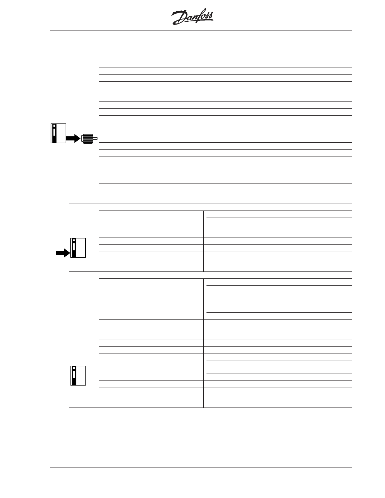
Product description
Quick setup
How to use this manual ........................ 5
For first-time Danfoss VLT® users ........ 5
For experienced Danfoss VLT® users... 5
Available documentation ...................... 5
In most cases ....................................... 6
Programming keys ............................... 6
External operation ................................ 6
Start-up ................................................ 6
If the factory setting has been changed 7
Quick setup .......................................... 7
Introduction .......................................... 8
Technology ........................................... 9
Sizing ................................................... 12
Product range....................................... 14
Technical data ...................................... 23
Dimensions........................................... 28
Description of terminals........................ 31
Connection examples........................... 32
About this manual
Installation
Mechanical installation ......................... 40
Electrical installation............................. 45
Connection of VLT
®
......................................................
46
Connection of motor ............................. 50
EMC installation ................................... 51
What is CE-labelling? ........................... 51
The control panel.................................. 60
Display layout ....................................... 61
Initialization........................................... 63
Avoid unwanted data change ............... 64
Menu build-up....................................... 65
Group description ................................. 66
Parameter description .......................... 82
Display messages ................................ 123
Operational instructions
Page 4

4 MG.30.A7.02 - VLT® is a registered Danfoss trademark
Special conditions
Galvanic isolation -
Earth leakage current ........................... 128
Extreme running conditions.................. 129
du/dt and peak voltage on motor.......... 130
Acoustic noise ...................................... 130
Thermal motor protection ..................... 130
Derating................................................ 131
EMC testresults .................................... 134
Vibration and shock.............................. 137
Air humidity .......................................... 137
Efficiency .............................................. 138
Mains supply
interference / harmonics....................... 139
Power factor ......................................... 139
Service
Fault messages ................................... 140
Electrostatic discharge (ESD)............... 141
Fault location ........................................ 142
Accessories
External mounting
of display .............................................. 146
Connection of brake resistors............... 146
Connection of option cards................... 146
Mounting of bonding plate for
UL approval.......................................... 148
Mounting of fan option.......................... 148
Factory settings
Factory settings .................................... 149
Index
Index .................................................... 154
Page 5
5MG.30.A7.02 - VLT® is a registered Danfoss trademark
About this manual
How to use this manual This manual has sections on the VLT®’s
performance and on installation and operation of the VLT®, as well as a section on
special conditions.
There is also a section on service and an
appendix for quick referral to factory settings. The index can be a help if you wish
to look up a specific item in the manual.
For first-time Danfoss
VLT® users
If you have not used a Danfoss VLT® before, “Quick setup” will be a help, and also
“Installation” and “Operational instructions”.
Pay attention to the safety rules on page
2 before start-up.
If you already have experience with the
Danfoss VLT
®
, you will find the “Quick
setup” section most useful.
For experienced Danfoss
VLT
®
users
For more information see the other sections, of which “EMC-correct installation”
and “Special conditions” will be particularly
useful.
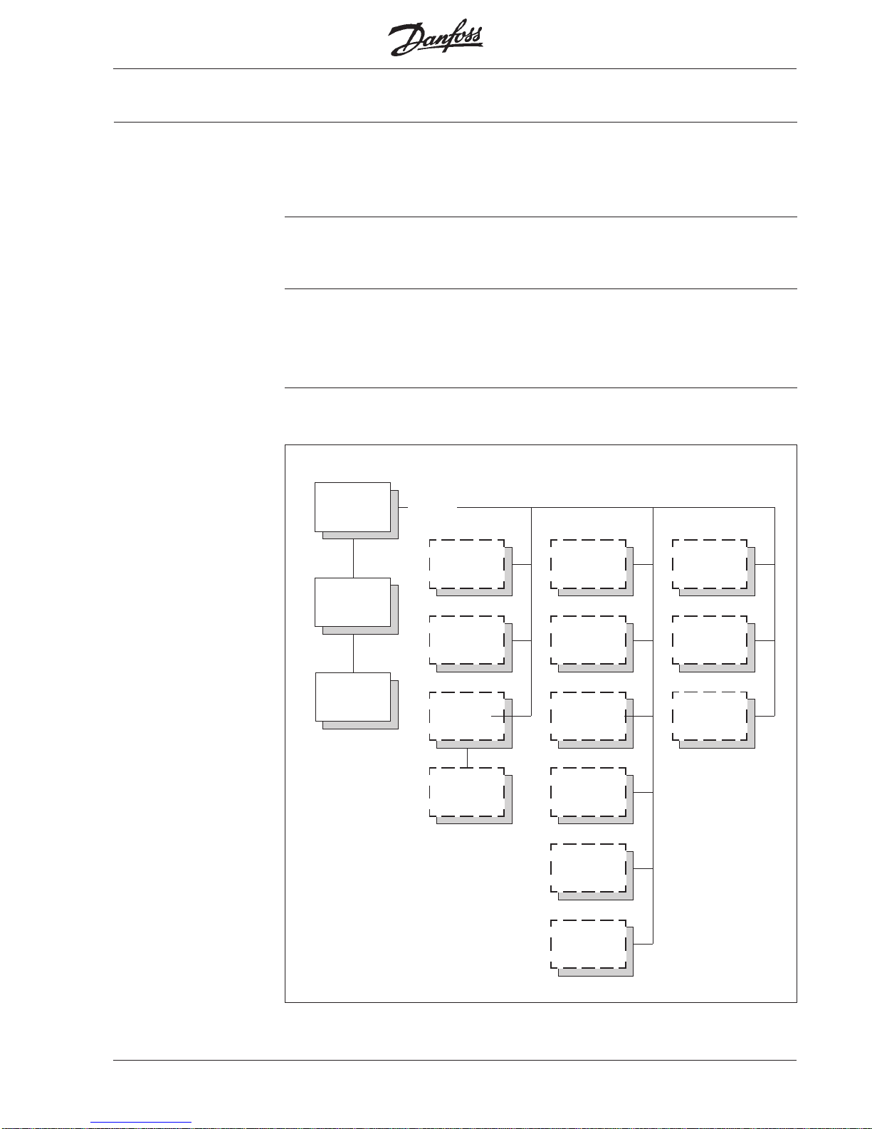
Available
documentation
The following chart shows what literature
is available on the VLT® 3000 Series.
Note that there can be deviations between different countries.
Option
Product
manual
MG.30.AX.02
Data sheet
MD.30.AX.02
All
users
Relay
option
MI.10.AX.YY
PC
Software
MZ.64.FX.YY
PROFIBUS
manual
MG.10.AX.YY
PROFIBUS
data sheet
MD.10.AX.YY
RFI
module
MI.62.FX.YY
RFI
option
MI.62.GX.YY
RFI - LC
module
MI.65.FX.YY
Clamp
module
MI.65.IX.YY
Brake
module
MI.62.GX.YY
LC
module
MI.65.FX.YY
RFI
option
MI.60.AX.YY
RFI
option
MI.60.BX.YY
Brake
resistor
MI.65.BX.YY
X = Revision of edition
YY = Language version
Page 6
6 MG.30.A7.02 - VLT® is a registered Danfoss trademark
In most cases In most cases it is sufficient to program
the VLT® according to items 1-10 (see
next page).
Note: All settings are based on factory settings, but the following must
be selected: 103, 104 and 105.
Screen for control cables, is mounted under terminal clamp according to
instructions on p. 57.
Connection example
Programming keys When the supply voltage is connected, the
VLT® is automatically in DISPLAY MODE
after start-up. Please note that the size and
voltage of the VLT
®
are shown on the
display during start-up. If the VLT® voltage
and size shown do not correspond to the
actual VLT
®
/mains voltage, the correct VLT
®
size and mains voltage can be selected in
parameter 650.
A potentiometer 1 kΩ is connected to
terminals 50, 53 and 55, see connection
example.
External operation
Start the frequency converter by connecting
+24 V D.C. (terminal 12) to start (terminal 18)
and freewheel stop (terminal 27).
Start-up
Press once to switch to MENU GROUP
MODE. From MENU GROUP MODE press
Menu
Menu
once to switch to MENU PARAMETER
MODE.
Use the
Data
key to switch to DATA MODE.
Data can now be changed.
The+and–keys are used to select a
group of parameters, one particular parameter or a data value.
Data values can only be changed using
the
+
and–keys. Pressing the
Menu
key
stores the new data value in the memory.
This also takes place automatically after 20
seconds if data values have been changed.
Quick setup
Page 7
7MG.30.A7.02 - VLT® is a registered Danfoss trademark
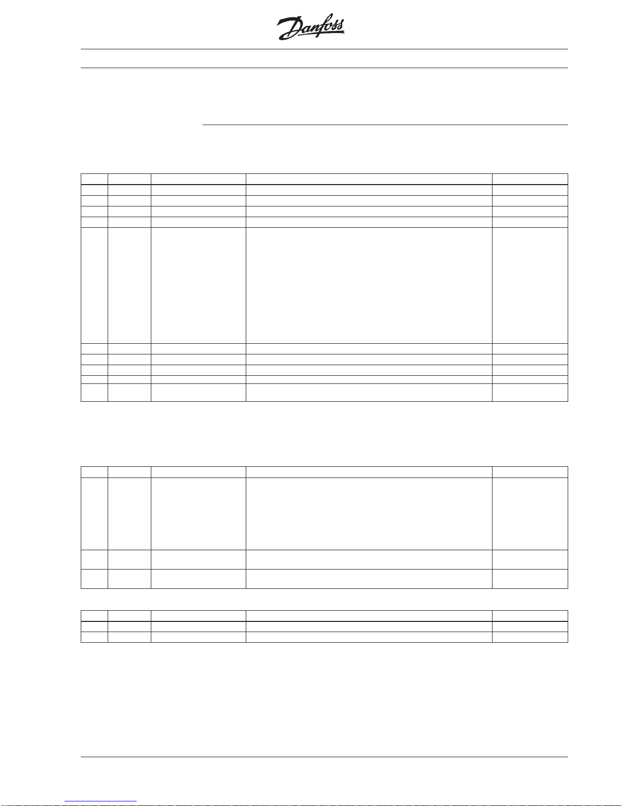
Item Parameter Description Settings Display
1 000 Language Select: "English" ENGLISH
2 103 Motor output See nameplate and select closest setting
3 104 Motor voltage See nameplate
4 105 Motor frequency See nameplate
Items 1-4 must be carried out first.
5 106 Automatic Select: "On". ON
motor adaption The compensation menus 109-113 are now tuned automatically.
During automatic motor adaption the motor should be unloaded or
loaded at max. 50%.
Automatic motor adaption is not possible in connection with
parallel running of several motors on one VLT
®
. This also applies
to motor outputs which cannot be set in parameter 103, and
synchronous, reluctance and other specialised motors.
After tuning the VLT
®
is reset by pressing the Stop/Reset key and
restarted by pressing the Start key.
Note: During automatic motor adaption the motor will start
for a short period.
6 201 Min. frequency Set required frequency
7 202 Max. frequency Set required frequency
8 215 Ramp-up 1 Set required ramp time
9 216 Ramp-down 1 Set required ramp time
10 Start frequency converter This is by supplying terminals 18 and 27 with 24 V D.C. from
terminal 12 or by using an external 24 V D.C. voltage.
Quick setup
If the factory setting
has been changed
If the factory setting has been changed
initialisation must be carried out.
In most cases it is sufficient to program
the VLT
®
according to items 1-10.
Quick setup
Standard motor running in constant torque application without a brake module on the frequency converter
The following settings are also used for specialised motors and parallel coupled motors, or variable torque
application or when a brake module is mounted
Item Parameter Description Settings Display
1 100 Load For normal applications with
constant torque:
Select: “Constant torque compensated”
CT WITH COMP
For
centrifugal pumps and fans:
Select: “VT medium” VT MODE-MED
For
centrifugal pumps and fans with heavy start:
Select: “VT Medium CT Start” VT MED W/CT
For
synchronous motors, parallel coupled motors or specialised motors
Select: “Constant torque”
CT MODE
2 300 Brake option If
brake option/module
is used:
Select: “Applied” APPLIED
3 Start frequency converter This is by applying 24 V D.C. to terminals 18 and 27 from
terminal 12 or by using external 24 V D.C. voltage.
The following settings are used for local operation and start
Item Parameter Description Settings Display
1 003 Operation mode Select: “Local” LOCAL
2 004 Local reference Set required output frequency using the "+" or "−" keys.
Page 8
8 MG.30.A7.02 - VLT® is a registered Danfoss trademark
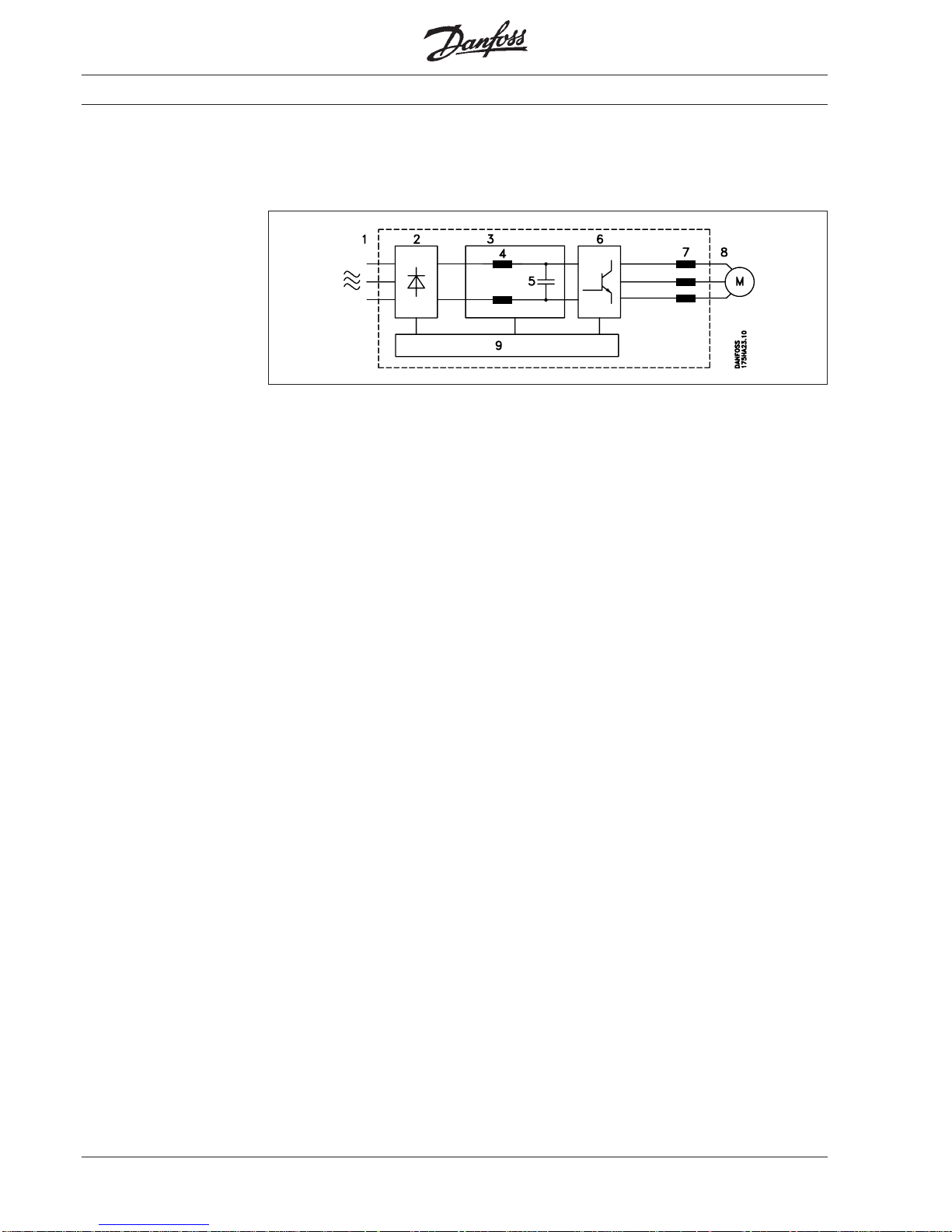
A frequency converter rectifies the a.c.
voltage to D.C. voltage and then converts
this D.C. voltage to A.C. voltage with
variable amplitude and frequency.
The variable voltage and frequency
supplying the motor make possible infinite
speed control of standard three-phase
asynchronous motors.
Control principle
1.
Mains supply
3 x 200 / 220 / 230 V A.C., 50/60 Hz
3 x 380 / 400 / 415 V A.C., 50/60 Hz
3 x 440 / 460 / 500 V A.C., 50/60 Hz
2.
Rectifier
Three-phase rectifier bridge rectifies
A.C. to D.C..
3.
Intermediate circuit
D.C. voltage = √2 x supply voltage.
4.
Coils in the intermediate circuit
Smooth the D.C. voltage and limit
the mains supply harmonics.
5.
Capacitors in the intermediate circuit
Smooth- the D.C. voltage.
6.
Inverter
Converts D.C. voltage to variable A.C.
voltage and variable frequency.
7.
Motor coils
Advantages of motor coils:
• You can use longer motor cables
• 100% short-circuit and earth-fault
protected
• Unlimited switching at the output of
the frequency converter.
• Reduces du/dt.
8.
Output
Variable A.C. voltage, 10 -100% of
the supply voltage.
Variable frequency: 0.5-120 / 0.5-500 Hz.
9.
Control card
This section controls and monitors the
power and inverter section, which
generates the pulse pattern by means
of which the D.C. voltage is converted
to variable A.C. voltage and variable
frequency.
Introduction
Page 9
9MG.30.A7.02 - VLT® is a registered Danfoss trademark
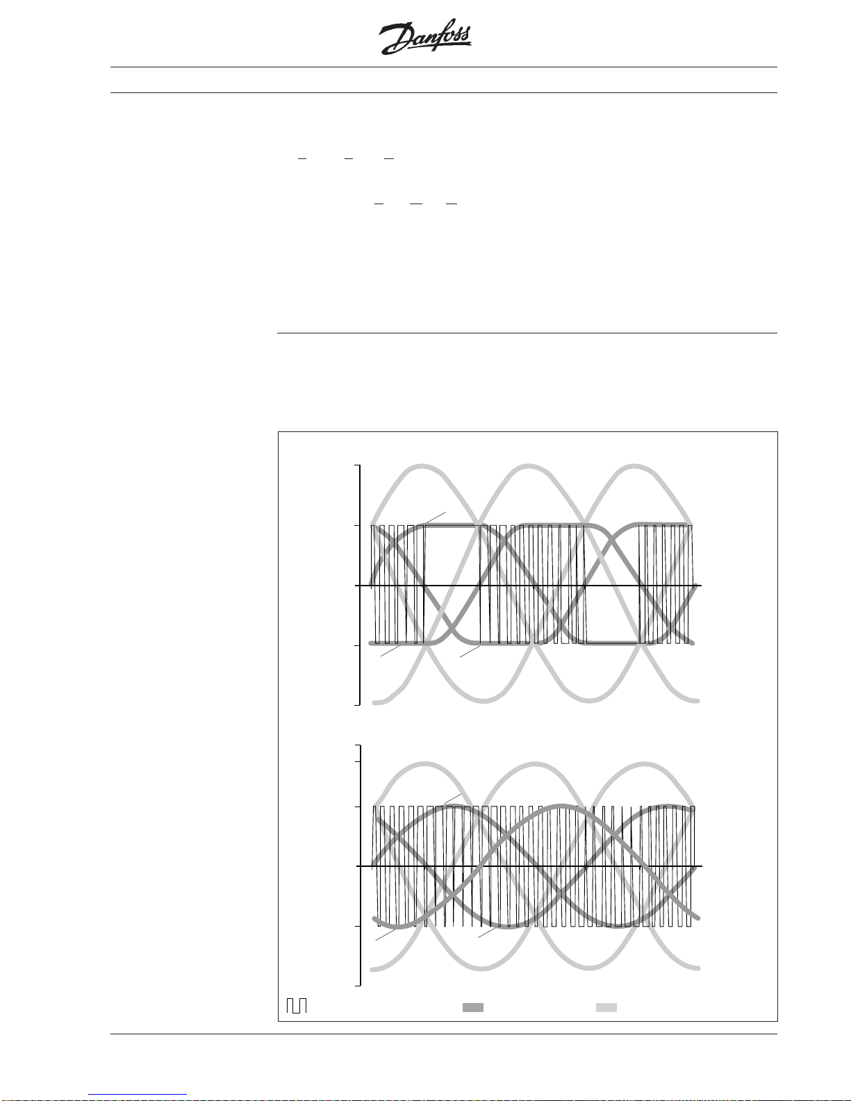
The features are obtained through a
special switching pattern: the switching
intervals are very short, which means high
switching frequency, and the six semiconductors of the inverter section are
alternately held inactive, in pairs, throughout a 60° sine period. The current wave
form of the motor current closely resembles
that obtained on mains operation. The
switching pause in 60° of the sine period
also means that full-rated motor voltage
can be obtained – and inverter switching
losses are reduced by about one third.
The figures below show the switching
pattern and the maximum motor voltage in
relation to the mains voltage according to
the VVC principle and the traditional PWM
principle, respectively.
The full-rated motor voltage and the
perfect current wave form mean that the
Danfoss VLT
®
3000 Series allows full motor performance without any derating –
just like running the motor on the mains.
Technology
VLT® 3000 Series frequency converters
use an inverter control system known as
the Voltage Vector Control (VVC)
developed by Danfoss.
The VVC principle is superior to the
traditional PWM (
Pulse Width Modulation)
principle used in most modern frequency
converters in the following ways:
• Full-rated motor voltage at rated motor
frequency
• Near perfect resemblance to the
sinusoidal mains supply
• Extremely low switching losses, resulting
in high converter efficiency
U
V
W
U
W
V
0,50
0,00
1,00
-0,50
-1.00
0 60 120 180 300 360240
U-V U-W W-U
0,50
0,00
1,00
-0,50
-1.00
0 60 120 180 300 360240
0,866
U-V V-W W-U
Motor voltage and switching pattern with the traditional PWM principle
Motor voltage and simplified switching pattern with the Danfoss VVC principle
Switching pattern for phase U Single-phase voltage Phase-phase voltage for motor
Page 10
10 MG.30.A7.02 - VLT® is a registered Danfoss trademark
The VLT® 3000 Series is delivered with a
number of standard components which
you would normally have to buy separately
such as motor coils, mains reactor DC link
coil and galvanic insulation (PELV).
These components built-in as standard
give you the following advantages:
• Save space and reduce costs
• Simplify the installation as the
VLT
®
3000 will meet most demands.
Factory programmed
U/f characteristics
Technology
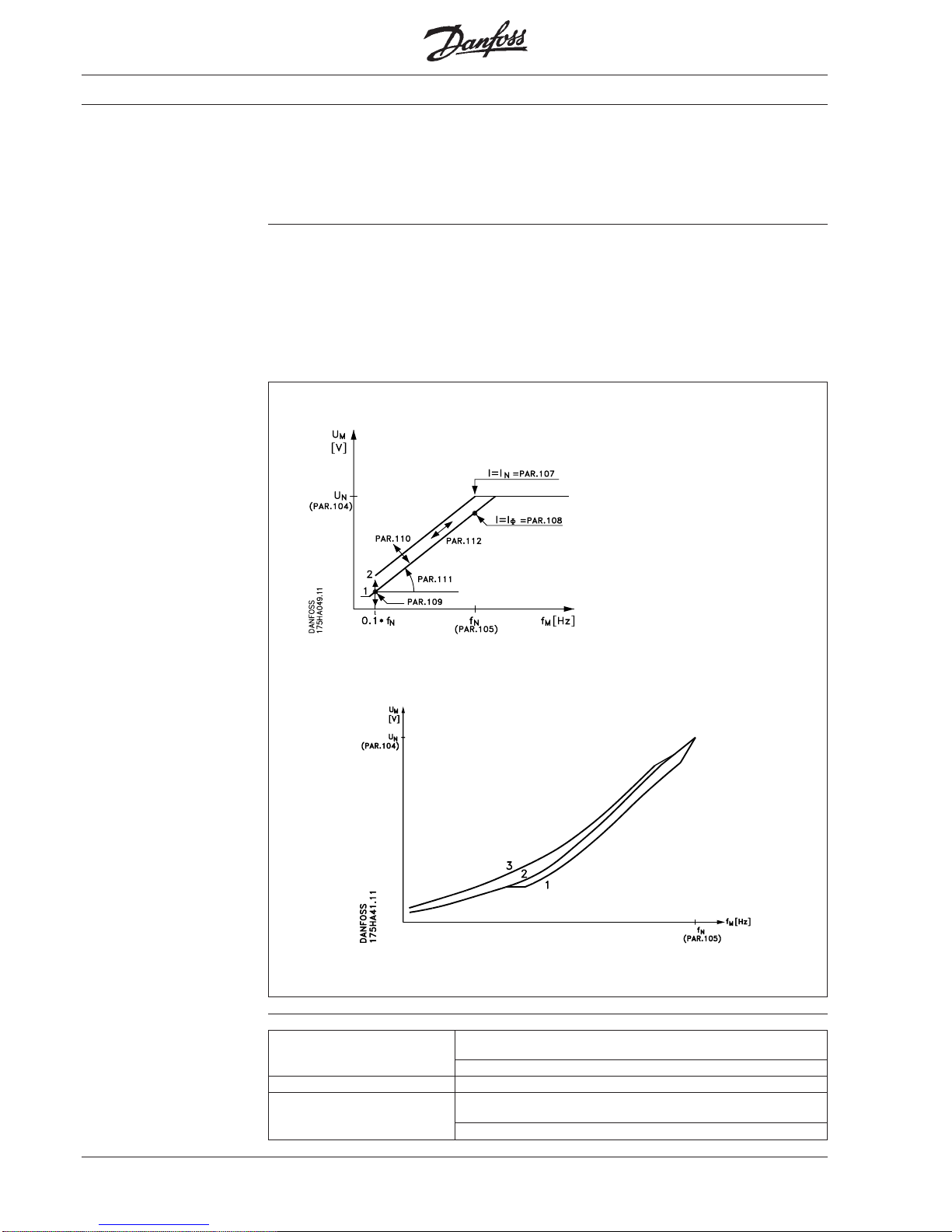
Depending on the type of load, the
VLT® 3000 Series has dynamic adapting or
factory programmed U/f characteristics
(motor voltage/frequency) giving the
correct magnetisation of the motor, thus
ensuring optimum dynamic, accuracy or
efficiency.
It is possible to choose between 3 U/f
characteristics for VT operation, offering
the choice of optimising the start torque or
reducing the noise level or power losses
from the motor. A new parameter (106)
called “Automatic motor tuning” optimizes
the motor parameters at constant load
torque.
Constant torque CT
(Parameter 100)
1: VT low
2: VT medium
3: VT high
Quadratic torque VT
(Parameter 100)
Control accuracy
Slip-compensated ±0.5% 5-50 Hz: VLT® 3011-3052
(depending on motor size) 10-50 Hz: VLT
®
3004-3008
±1.0% 5-50 Hz: VLT
®
3004-3052 (10-140% load change)
PID (closed loop) ±0.1% 5-50 Hz: (−140 - +140% load change)
Open loop (digital) ±0.01% 0.5-120 Hz
0.5-500 Hz
±0.05% Frequency resolution (digital)
(10-90% load change)
(frequency stability)
Page 11

11MG.30.A7.02 - VLT® is a registered Danfoss trademark
It is easy for the user to program the
required functions on the keyboard of the
VLT® 3000 Series or via the terminals or
the RS 485 interface.
The digital technique used in the VLT
®
3000 Series makes it possible to program
the different control inputs and signal
outputs, and to select 4 different userdefined setups.
Programmable
control inputs and
signal outputs
in 4 setups
Protected against mains
disturbance
The VLT® 3000 Series is protected against
transients arising on the mains, e.g. when
you switch in power factor phase correction
capacitors or when the supply is subject to
lightning strikes.
Rated motor voltage and full torque can be
maintained down to 10% undervoltage on
the supply mains.
Low disturbance on
the mains
As the VLT
®
3000 Series has coils in the
intermediate circuit built-in as standard the
harmonic generation is low.
This gives a good power factor, thus
reducing the harmonic load on the mains
supply.
Effective radio
frequency interference
suppression (EMC)
Technology
As standard the VLT® 3000 Series is
delivered with built-in motor coils. This
means that it is possible to install a long
Current measurement in all three motor
phases gives perfect protection of the VLT
®
3000 series in the event of short circuits or
earth faults on the motor terminals.
The continuous monitoring of the three
motor phases makes switching on the
motor cables possible e.g. by opening/
closing a contactor.
Long motor cables
Advanced
VLT® protection
cable between motor and frequency
converter without any additional coils.
Galvanic isolation
With the VLT® 3000 Series safety isolation
is standard, as the high-voltage parts of
the power section are galvanically isolated
from the low-voltage parts of the control
section in accordance with VDE 0160/0106
(PELV).
Advanced
motor protection
The VLT® 3000 Series has a built-in electronic thermal motor protection.
The frequency converter calculates the
motor temperature on the basis of voltage,
current, frequency and time.
Therefore it is superior to the traditional
bi-metallic protection where the altered
cooling conditions due to the speed control
are not taken into consideration.
The thermal motor protection is comparable with thermal relay in the motor cables.
To achieve optimum protection against
overheating of the motor when covered or
blocked, or in case the ventilation should
fail, it is possible to build in a thermistor
and connect this to the frequency converter thermistor input (terminal 16, see
page 102).
The effective monitoring of the three supply
phases means that the VLT
®
3000 Series
stops in the event of a missing phase. In
this way overloading of the inverter and the
capacitors of the intermediate circuit, which
would reduce the lifetime of the frequency
converter drastically, can be avoided.
The VLT
®
3000 Series has built-in thermal
protection of the unit as standard. The
function turns off the inverter on thermal
overload.
The VLT
®
3000 Series can be delivered with
an RFI filter complying with EN 55011.
Filters are available as options or modules.
Some VLT
®
types have a mains filter as
standard in compliance with grade 1, class A.
Page 12
12 MG.30.A7.02 - VLT® is a registered Danfoss trademark
Choice of frequency
converter size
The frequency converter must be chosen
on the basis of the actual motor current I
M
at maximum load of the plant.
The rated continuous output current I
VLT,N
must be equal to or higher than the
required motor current.
Sizing
Example:
In a heating plant (quadratic load) the
pump motor is a 7.5 kW, 3 x 380 V, which
at max. load takes up 14 A.
Choose a VLT
®
3008 which can supply
16 A (I
VLT,N
) continuously.
Mains: 3 x 200/220/230 V and 3 x 220/230/240 V (see technical data)
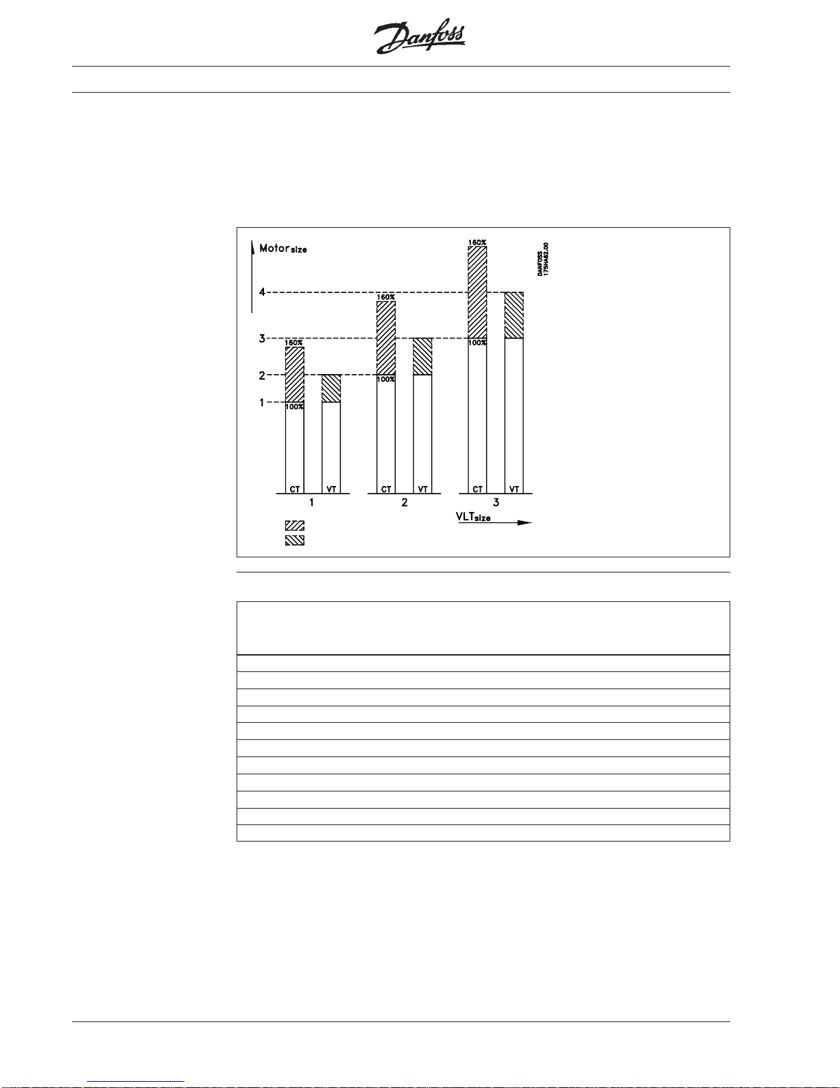
Which one
to choose?
The
VLT
®
types larger
than 3004 (3008 at 500 V) have
a higher output when using
quadratic load,
referred to as VT load
(variable torque).
Some technical specifications
might change from
CT to VT mode (e.g. the max.
motor cable length
decreases).
: Intermittent operation
: In continuous operation some specifications might change
CT VT CT VT CT VT
Typical shaft Constant output Constant output
VLT
®
type output current I
VLT.N
power at 230 V
[kW] [A] [kVA]
3002 1.1 5.4 2.1
3003 1.5 7.8 3.1
3004 2.2 10.5 4.2
3006 4.0 5.5 19 25 7.6 10.0
3008 5.5 7.5 25 32 10.0 12.7
3011 7.5 11 32 46 12.7 18.3
3016 11 15 46 61 18.3 24.3
3022 15 22 61 88 24.3 35.1
3032 22 30 80 104 31.9 41.4
3042 30 37 104 130 41.4 51.8
3052 37 45 130 154 51.8 61.3
CT: Constant torque
VT: Variable torque (quadratic load)
Page 13
13MG.30.A7.02 - VLT® is a registered Danfoss trademark
Mains: 380/400/415 V
Typical shaft Constant output Constant output
VLT
®
type output current I
VLT,N
power at 415 V
[kW] [A] [kVA]
3002 1.1 2.8 2.0
3003 1.5 4.1 2.9
3004 2.2 5.6 4.0
3006 4.0 5.5 10.0 13.0 7.2 9.3
3008 5.5 7.5 13.0 16.0 9.3 11.5
3011 7.5 11 16.0 24.0 11.5 17.3
3016 11 15 24.0 32.0 17.3 23.0
3022 15 22 32.0 44.0 23.0 31.6
3032 22 30 44.0 61.0 31.6 43.8
3042 30 37 61.0 73.0 43.8 52.5
3052 37 45 73.0 88.0 52.3 63.3
3060 45 55 86.0 105 61.8 75.5
3075 55 75 105 139 75.5 99.9
3100 75 90 139 168 99.9 120
3125 90 110 168 205 120 147
3150 110 132 205 243 147 174
3200 132 160 243 302 174 217
3250 160 200 302 368 217 264
CT VT CT VT
CT: Constant torque
VT: Variable torque (quadratic load)
CT VT CT VT
CT VT
CT: Constant torque
VT: Variable torque (quadratic load)
Sizing
Typical shaft Constant output Constant output
VLT
®
type output current I
VLT,N
power at 500 V
[kW] [A] [kVA]
3002 1.1 2.6 2.3
3003 1.5 3.4 2.9
3004 2.2 4.8 4.1
3006 4.0 8.2 7.1
3008 5.5 11.1 9.6
3011 7.5 11 14.5 21.7 12.6 18.8
3016 11 15 21.7 27.9 18.8 24.1
3022 15 22 27.9 41.4 24.1 36.0
3032 22 30 41.4 54.0 36.0 46.8
3042 30 37 54.0 65.0 46.8 56.3
3052 37 45 65.0 78.0 56.3 67.5
3060 55 75 77.0 96.0 66.7 83.1
3075 75 90 96.0 124 83.1 107
3100 90 110 124 156 107 135
3125 110 132 156 180 135 156
3150 132 160 180 240 156 208
3200 160 200 240 302 208 262
3250 200 250 302 361 262 313
CT VT
Mains: 440/460/500 V
Page 14
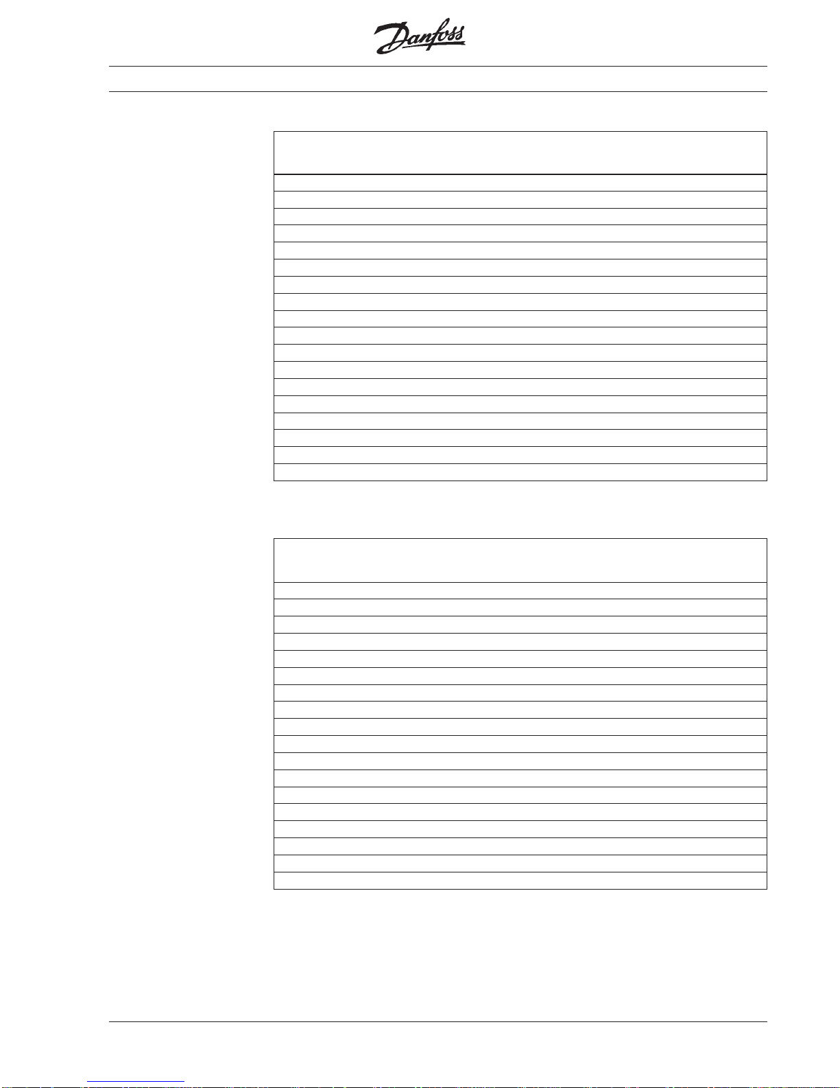
14 MG.30.A7.02 - VLT® is a registered Danfoss trademark
VLT
®
type 3002 - 3004, 200/230 V /
VLT
®
type 3002 - 3008, 380/415 V /
VLT
®
type 3002 - 3008, 440/500 V
Product range
RFI option RFI module RFI-LC module LC motor filter *) LC module Brake module Clamp module
175U0253 175U0252 175H6198/6199 175H5147
*) Made for Danfoss A/S by the firm Platthaus
Remote box
175H1788
IP 00 IP 54 IP 21 option IP 21 option
with fan without fan
175H7040/7008 175H1007/7007
1IP 21 option H1007 H1007 H1007 H7040 H1007 H1007 H1007 H7040 H1007 H1007 3) H1007 3) H1007 3)
IP 21 option with UL approval H7007 - H7007 H7008 - H7007 - - H7007 - - H7007
3
)
RFI module for IP 00 / 21 H7037 H7037 H7037 H7037 H7037 H7037 H7037
2
) H7037 2) H7037 2) H7037 2) H7037 2) H7037 2)
RFI option for IP 00 / 21 H7038
1
) H7038 1) H7038 1) H7038 1) H7038 1) H7038 1) H7038 H7038 H7038 H7038 H7038 H7038
RFI option for IP 54 H7038 H7038 H7038 H7038 H7038 H7038 H7038 H7038 H7038 H7038 H7038 H7038
RFI-LC module for IP 00 - U0253 U0253 - U0253
4
) U0253 -----RFI motor filter option for unscreened motor cable H7083 H7083 H7083 H7083 H7083 H7083 H7083 H7083 H7083 H7083 H7083 H7083
RFI motor filter module for unscreened motor cable H7084 H7084 H7084 H7084 H7084 H7084 H7084 H7084 H7084 H7084 H7084 H7084
LC module for IP 00 U0252 U0252 - U0252 U0252 - U0252 U0252 - U0252 U0252 LC motor filter for IP 00 191G0216 - 191G0209 191G0217 - 191G0209 - - 191G0209 - - 191G0210
Clamp module for IP 00 H5147 H5147 H5147 H5147 H5147 H5147 H5147 H5147 H5147 H5147 H5147 H5147
Brake module for IP 00 / 21 H6198 H6199 H6199 H6198 H6199 H6199 H6199 H6199 H6199 H6199 H6199 H6199
Remote box H1788 H1788 H1788 H1788 H1788 H1788 H1788 H1788 H1788 H1788 H1788 H1788
Relay option H7063 H7063 H7063 H7063 H7063 H7063 H7063 H7063 H7063 - - PROFIBUS option H4696
Modbus Plus option contact Danfoss
PC software ( GB 175H2850) ( D 175H2876) ( DK 175H2877)
3002 / 3003 3004 3006 3008
Description 220 V 380 V 500 V 220 V 380 V 500 V 380 V 380 V 500 V 380 V 380 V 500 V
CT VT CT VT
All code numbers: 175XXXXX. CT: Constant torque / VT: Variable torque (quadratic load)
1
) Can only be mounted in units with brake function.2) The RFI filter option (175H7038) may be beneficial.3) Only bottom can be used.4) Forced cooling
needed.
"-" Cannot be delivered.
200 / 220 / 230 V 380 / 400 / 415 V
440 / 460 / 500 V
VLT
®
Description kW Code no.
type
VLT
®
Description kW Code no.
type
VLT
®
Description kW Code no.
type
IP 00 1,1 175H4131
IP 00 with brake 1,1 175H4132
3002 IP 21 (as option) 1,1 175H1007
IP 54 1,1 175H4133
IP 54 with brake 1,1 175H4134
IP 00 1,5 175H4135
IP 00 with brake 1,5 175H4136
3003 IP 21 (as option) 1,5 175H1007
IP 54 1,5 175H4137
IP 54 with brake 1,5 175H4138
IP 00 2,2 175H4139
IP 00 with brake 2,2 175H4140
3004 IP 21 (as option) 2,2 175H7040
IP 54 2,2 175H4141
IP 54 with brake 2,2 175H4142
IP 00 1,1 175H7238
IP 00 with brake 1,1 175H7239
3002 IP 21 as option) 1,1 175H1007
IP 54 1,1 175H7240
IP 54 with brake 1,1 175H7241
IP 00 1,5 175H7242
IP 00 with brake 1,5 175H7243
3003 IP 21 (as option) 1,5 175H1007
IP 54 1,5 175H7244
IP 54 with brake 1,5 175H7245
IP 00 2,2 175H7246
IP 00 with brake 2,2 175H7247
3004 IP 21 (as option) 2,2 175H1007
IP 54 2,2 175H7248
IP 54 with brake 2,2 175H7249
IP 00 4,0 175H7264
IP 00 with brake 4,0 175H7265
3006 IP 21 (as option) 4,0 175H7040
IP 54 4,0 175H7266
IP 54 with brake 4,0 175H7267
IP 00 5,5 175H7268
IP 00 with brake 5,5 175H7269
3008 IP 21 (as option) 5,5 175H1007
IP 54 5,5 175H7270
IP 54 with brake 5,5 175H7271
IP 00 1,1 175H1729
IP 00 with brake 1,1 175H1730
3002 IP 21 (as option) 1,1 175H1007
IP 54 1,1 175H1731
IP 54 with brake 1,1 175H1732
IP 00 1,5 175H1733
IP 00 with brake 1,5 175H1734
3003 IP 21 (as option) 1,5 175H1007
IP 54 1,5 175H1735
IP 54 with brake 1,5 175H1736
IP 00 2,2 175H1737
IP 00 with brake 2,2 175H1738
3004 IP 21 (as option) 2,2 175H1007
IP 54 2,2 175H1739
IP 54 with brake 2,2 175H1740
IP 00 4,0 175H1741
IP 00 with brake 4,0 175H1742
3006 IP 21 (as option) 4,0 175H1007
IP 54 4,0 175H1743
IP 54 with brake 4,0 175H1744
IP 00 5,5 175H1745
IP 00 with brake 5,5 175H1746
3008 IP 21 (as option) 5,5 175H1007
IP 54 5,5 175H1747
IP 54 with brake 5,5 175H1748
Page 15
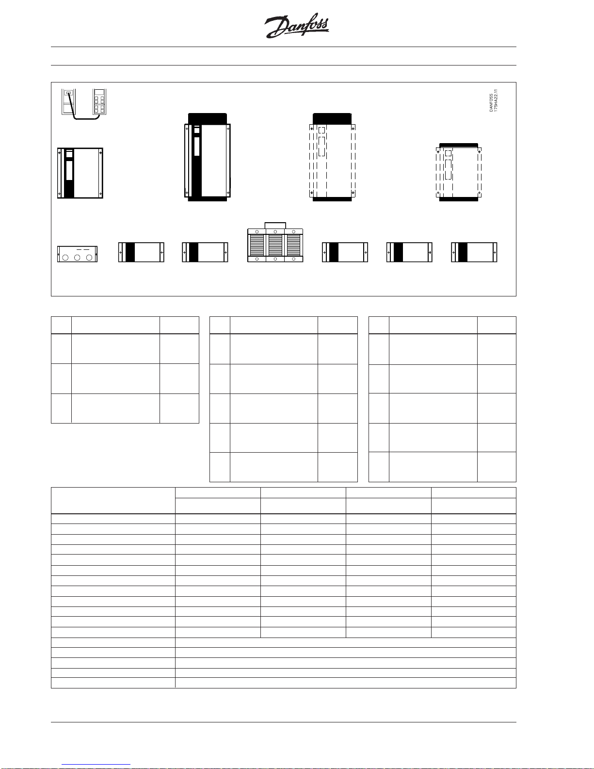
15MG.30.A7.02 - VLT® is a registered Danfoss trademark
VLT
®
type 3006 - 3022, 200/230 V /
VLT
®
type 3011 - 3052, 380/415 V /
VLT
®
type 3011 - 3052, 440/500 V
Product range
IP 20 IP 54 RFI option LC filter *) Clamp module
*) Made for Danfoss A/S by the firm Platthaus
IP 20 4.0 175H4449
IP 20 with RFI 4.0 175H4450
IP 20 with brake 4.0 175H4451
IP 20 with RFI + brake 4.0 175H4452
3006
IP 54 4.0 175H4453
IP 54 with RFI 4.0 175H4454
IP 54 with brake 4.0 175H4455
IP 54 with RFI + brake 4.0 175H4456
IP 20 5.5 175H4457
IP 20 with RFI 5.5 175H4458
IP 20 with brake 5.5 175H4459
IP 20 with RFI + brake 5.5 175H4460
3008
IP 54 5.5 175H4461
IP 54 with RFI 5.5 175H4462
IP 54 with brake 5.5 175H4463
IP 54 with RFI + brake 5.5 175H4464
IP 20 7.5 175H4465
IP 20 with RFI 7.5 175H4466
IP 20 with brake 7.5 175H4467
IP 20 with RFI + brake 7.5 175H4468
3011
IP 54 7.5 175H4469
IP 54 with RFI 7.5 175H4470
IP 54 with brake 7.5 175H4471
IP 54 with RFI + brake 7.5 175H4472
IP 20 11.0 175H4473
IP 20 with RFI 11.0 175H4474
IP 20 with brake 11.0 175H4475
IP 20 with RFI + brake 11.0 175H4476
3016
IP 54 11.0 175H4477
IP 54 with RFI 11.0 175H4478
IP 54 with brake 11.0 175H4479
IP 54 with RFI + brake 11.0 175H4480
IP 20 15.0 175H4520
IP 20 with RFI 15.0 175H4521
IP 20 with brake 15.0 175H4522
IP 20 with RFI + brake 15.0 175H4523
3022
IP 54 15.0 175H4524
IP 54 with RFI 15.0 175H4525
IP 54 with brake 15.0 175H4526
IP 54 with RFI + brake 15.0 175H4527
200 / 220 / 230 V 380 / 400 / 415 V
440 / 460 / 500 V
VLT
®
Description kW Code no.
type
IP 20 7.5 175H7272
IP 20 with RFI 7.5 175H7273
IP 20 with brake 7.5 175H7274
IP 20 with RFI + brake 7.5 175H7275
3011
IP 54 7.5 175H7276
IP 54 with RFI 7.5 175H7277
IP 54 with brake 7.5 175H7278
IP 54 with RFI + brake 7.5 175H7279
IP 20 11.0 175H7280
IP 20 with RFI 11.0 175H7281
IP 20 with brake 11.0 175H7282
IP 20 with RFI + brake 11.0 175H7283
3016
IP 54 11.0 175H7284
IP 54 with RFI 11.0 175H7285
IP 54 with brake 11.0 175H7286
IP 54 with RFI + brake 11.0 175H7287
IP 20 15.0 175H7288
IP 20 with RFI 15.0 175H7289
IP 20 with brake 15.0 175H7290
IP 20 with RFI + brake 15.0 175H7291
3022
IP 54 15.0 175H7292
IP 54 with RFI 15.0 175H7293
IP 54 with brake 15.0 175H7294
IP 54 with RFI + brake 15.0 175H7295
IP 20 22.0 175H1671
IP 20 with RFI 22.0 175H1672
IP 20 with brake 22.0 175H1673
IP 20 with RFI + brake 22.0 175H1674
3032
IP 54 22.0 175H1675
IP 54 with RFI 22.0 175H1676
IP 54 with brake 22.0 175H1677
IP 54 with RFI + brake 22.0 175H1678
IP 20 30.0 175H1679
IP 20 with RFI 30.0 175H1680
IP 20 with brake 30.0 175H1681
IP 20 with RFI + brake 30.0 175H1682
3042
IP 54 30.0 175H1683
IP 54 with RFI 30.0 175H1684
IP 54 with brake 30.0 175H1685
IP 54 with RFI + brake 30.0 175H1686
IP 20 37.0 175H1687
IP 20 with RFI 37.0 175H1688
IP 20 with brake 37.0 175H1689
IP 20 with RFI + brake 37.0 175H1690
3052
IP 54 37.0 175H1691
IP 54 with RFI 37.0 175H1692
IP 54 with brake 37.0 175H1693
IP 54 with RFI + brake 37.0 175H1694
VLT
®
Description kW Code no.
type
IP 20 7.5 175H4401
IP 20 with RFI 7.5 175H4402
IP 20 with brake 7.5 175H4403
IP 20 with RFI + brake 7.5 175H4404
3011
IP 54 7.5 175H4405
IP 54 with RFI 7.5 175H4406
IP 54 with brake 7.5 175H4407
IP 54 with RFI + brake 7.5 175H4408
IP 20 11.0 175H4409
IP 20 with RFI 11.0 175H4410
IP 20 with brake 11.0 175H4411
IP 20 with RFI + brake 11.0 175H4412
3016
IP 54 11.0 175H4413
IP 54 with RFI 11.0 175H4414
IP 54 with brake 11.0 175H4415
IP 54 with RFI + brake 11.0 175H4416
IP 20 15.0 175H4417
IP 20 with RFI 15.0 175H4418
IP 20 with brake 15.0 175H4419
IP 20 with RFI + brake 15.0 175H4420
3022
IP 54 15.0 175H4421
IP 54 with RFI 15.0 175H4422
IP 54 with brake 15.0 175H4423
IP 54 with RFI + brake 15.0 175H4424
IP 20 22.0 175H4425
IP 20 with RFI 22.0 175H4426
IP 20 with brake 22.0 175H4427
IP 20 with RFI + brake 22.0 175H4428
3032
IP 54 22.0 175H4429
IP 54 with RFI 22.0 175H4430
IP 54 with brake 22.0 175H4431
IP 54 with RFI + brake 22.0 175H4432
IP 20 30.0 175H4433
IP 20 with RFI 30.0 175H4434
IP 20 with brake 30.0 175H4435
IP 20 with RFI + brake 30.0 175H4436
3042
IP 54 30.0 175H4437
IP 54 with RFI 30.0 175H4438
IP 54 with brake 30.0 175H4439
IP 54 with RFI + brake 30.0 175H4440
IP 20 37.0 175H4441
IP 20 with RFI 37.0 175H4442
IP 20 with brake 37.0 175H4443
IP 20 with RFI + brake 37.0 175H4444
3052
IP 54 37.0 175H4445
IP 54 with RFI 37.0 175H4446
IP 54 with brake 37.0 175H4447
IP 54 with RFI + brake 37.0 175H4448
VLT
®
Description kW Code no.
type
RFI option for IP 20 / 54 H5353 H5355 H5353 H5355 H5353 H5355 H5355
Clamp module for IP 00 H5147 H5147 H5147 H5147 H5147 H5147 H5147
Remote box H1788 H1788 H1788 H1788 H1788 H1788 H1788
LC motor filter IP 00 191G0218-219-220 - 191G0202-203-204 191G0205-206-207 191G0210-211-212 191G0213 191G0214-215
PROFIBUS option H4696
Modbus Plus option contact Danfoss
PC software ( GB 175H2850) ( D 175H2876) ( DK 175H2877)
3006-3011 3016-3022 3011-3022 3032-3052 3011-3022 3032 3042-3052
Description
220 V 220 V 380 V 380 V 500 V 500 V 500 V
Remote box
175H1788
All code numbers: 175XXXXX.
"-" Cannot be delivered.
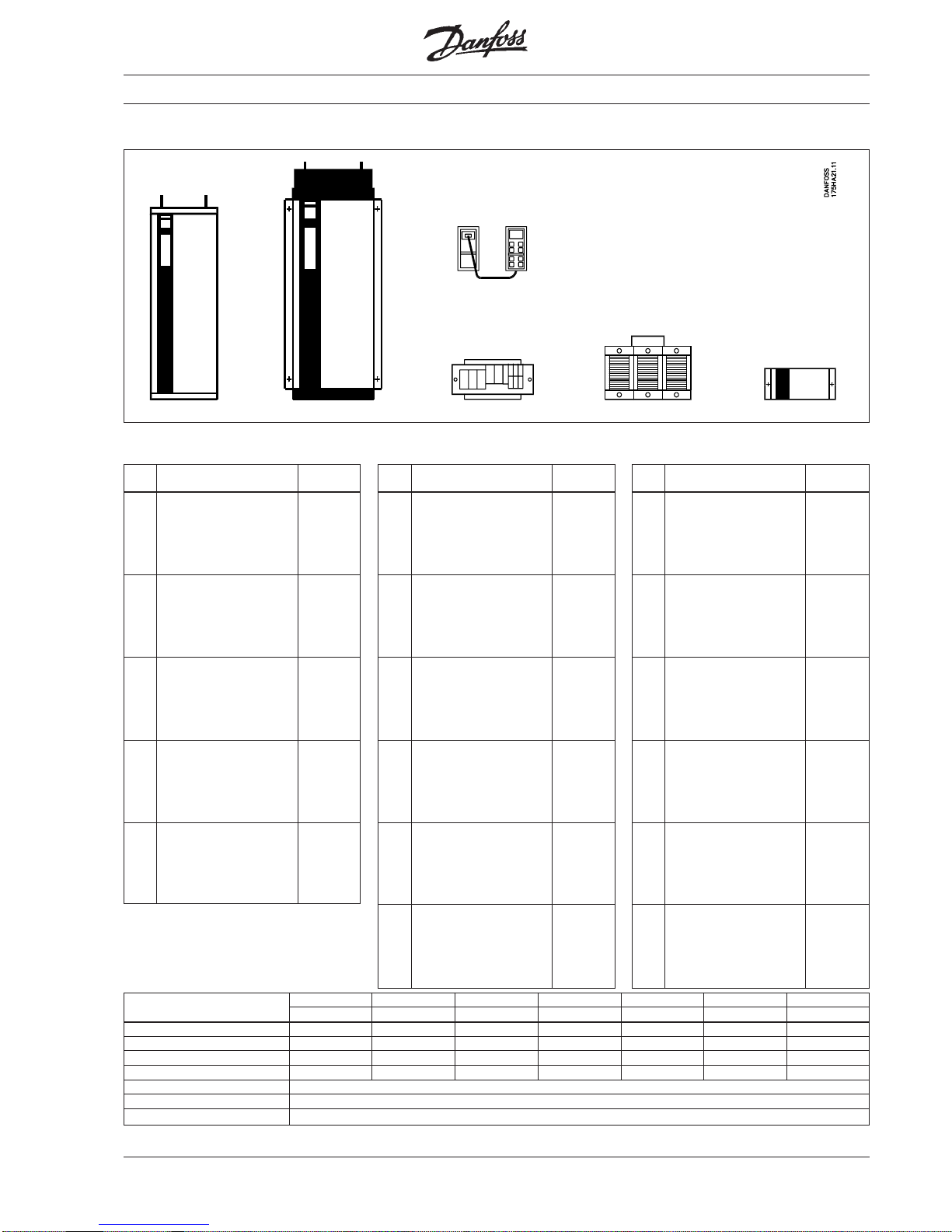
Page 16
16 MG.30.A7.02 - VLT® is a registered Danfoss trademark
VLT® type 3032 - 3052, 220/440 V, VLT® type 3060 - 3250, 380/440/500 V
Product range
NEMA 1/12
IP 21/54
only wall
mounting
Base
IP 20
RFI filter
NEMA 1/12
IP 21/54
including
base
NEMA 12
IP 54
RFI mounted
with filter,
including base
Optional
base for VLT
®
3100-3150
mounting cabinet/
RFI filter
Brake module
NEMA 12
IP 54
NEMA 1/12
IP 21/54
without base
(option)
NEMA 12
IP 54
RFI mounted
with filter
without base
(option)
Remote box
175H1788
IP 21 45 175L3000
3060
IP 54 45 175L3007
IP 21 55 175L3001
3075
IP 54 55 175L3008
IP 21 75 175L3002
3100
IP 54 75 175L3009
IP 21 90 175L3003
3125
IP 54 90 175L3010
IP 21 110 175L3004
3150
IP 54 110 175L3011
IP 21 132 175L3005
3200
IP 54 132 175L3012
IP 21 160 175L3006
3250
IP 54 160 175L3013
380/440/500 V
VLT
®
Description kW Code no.
type
175L3535
175L3437
175L3490
175L3489
175L3414
175L3415
175L3534
175L3432
175L3419
175L3462
175L3563
175L3475
175L3439
Fuses
Description Amp Bussmann 3100 3125 3150 3200 3250
name 3060 3075
Input fuse 150 T-Tron JJS
Input fuse 250 T-Tron JJS
Input fuse 300 T-Tron JJS
Input fuse 450 T-Tron JJS
Input fuse 500 T-Tron JJS
Charge fuse 9 KT-9
Charge fuse 10 KT-10
Charge fuse 12 KT-12
Fuse for fan 1.5 FNQ-R-1-1/2
Voltage supply 5 KTK-5
Fuse 250 170L5021
1BK/75
Fuse 315 170L5015
1BK/75
Fuse, dynamic
brake 20 KTK-20
IP 21 22 175L4500
3032
IP 54 22 175L4503
IP 21 30 175L4501
3042
IP 54 30 175L4504
IP 21 37 175L4502
3052
IP 54 37 175L4505
Options
Brake module IP54 175L3656
Mounting cabinet with main switch, IP 54 175L3038
(175A)
Mounting cabinet with main switch, IP 54 175L3039
(200A)
Mounting cabinet without main switch IP 54 175L3653
RFI module IP20 VLT 3032-3052 175L3665
RFI module IP54 VLT 3032-3052 175L3666
220/230/240 V
VLT
®
Description kW Code no.
type
Description 3060 3075 3100 3125 3150 3200 3250
Brake module IP 54 175L3030 175L3031
RFI module IP20 175L3657 175L3658 175L3659 175L3660
RFI module IP54 175L3661 175L3662 175L3663 175L3664
Mounting cabinet IP54 with main switch 175L3038(175A) 175L3040(200A) 175L3042(400A)
Mounting cabinet IP54 with main switch 175L3039(200A) 175L3041(400A) 175L3043(600A)
Mounting cabinet IP54 without main switch 175L3653 175L3654 175L3655
Base for floor installation for VLT
®
- 175L3047 Included
Base for RFi/mounting cabinet IP54 - 175L3048 Included
PROFIBUS option 175H4754
Modbus Plus option Contact Danfoss
PC software ( GB 175H2850) ( D 175H2876) ( DK 175H2877)
Remote box 175H1788
Terminal adapter kit 175L3640 175L3641 175L3642
3032 - 3052
Page 17
17MG.30.A7.02 - VLT® is a registered Danfoss trademark
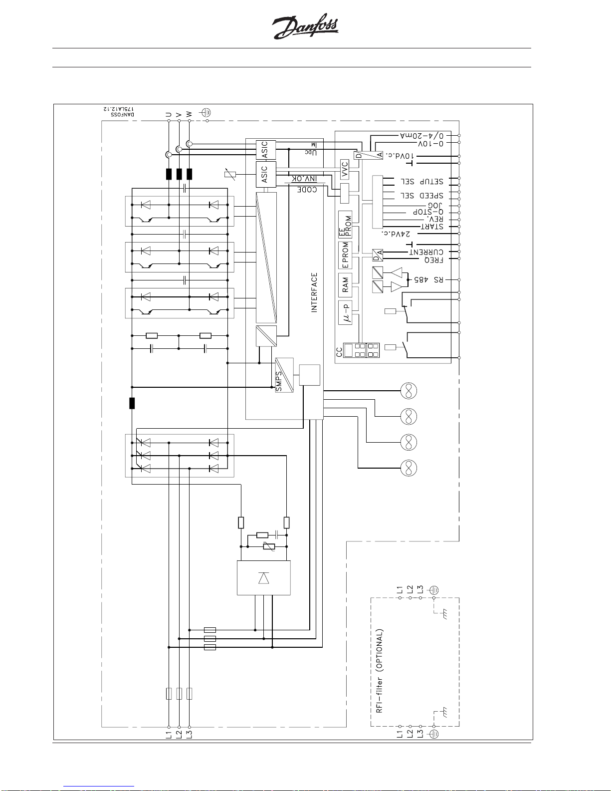
Product range
Function diagram for
VLT® type 3002 - 3006 380/415 V, VLT® type 3002 - 3008 440/500 V and VLT® type 3002 - 3004 200/230 V
*) Only 220/230 V and 440/500 V.
Page 18
18 MG.30.A7.02 - VLT® is a registered Danfoss trademark
Function diagram for VLT® type 3008, 385/415 V
Product range
Page 19
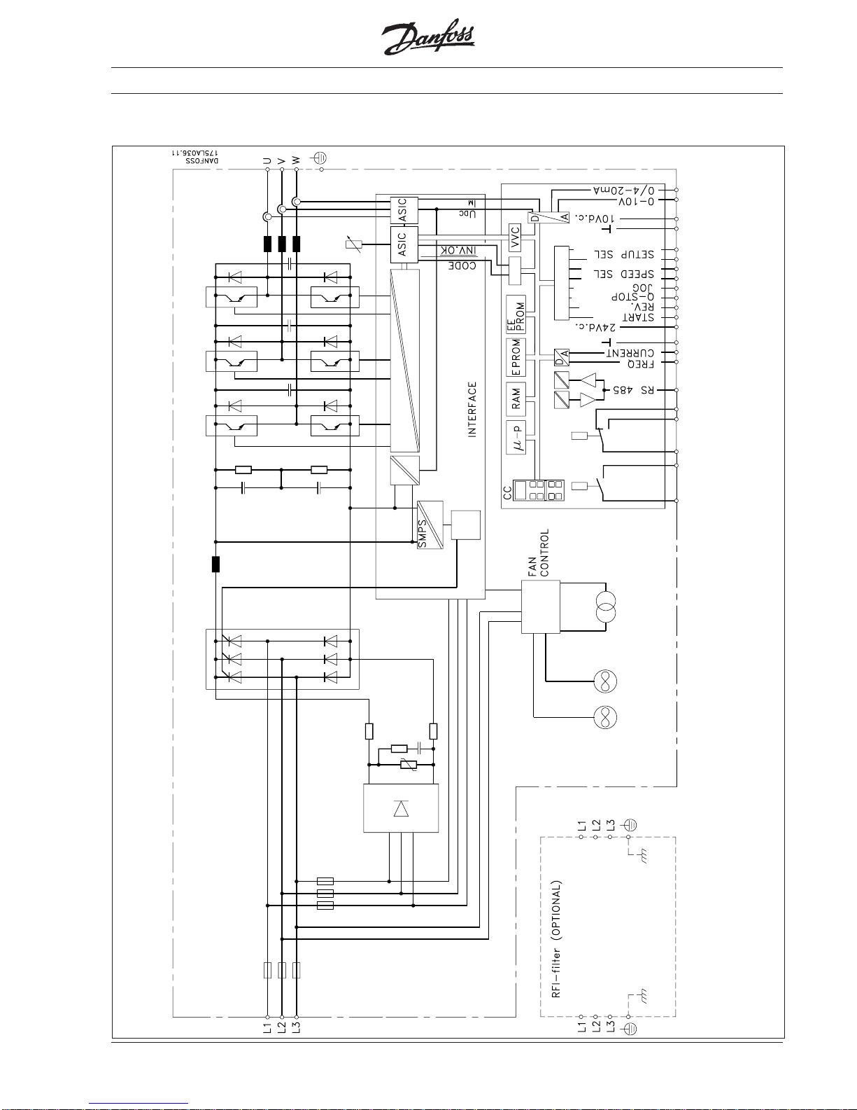
19MG.30.A7.02 - VLT® is a registered Danfoss trademark
Function diagram for VLT® type 3011 - 3052 380/500 V, VLT® type 3006 - 3022 200/230 V
Product range
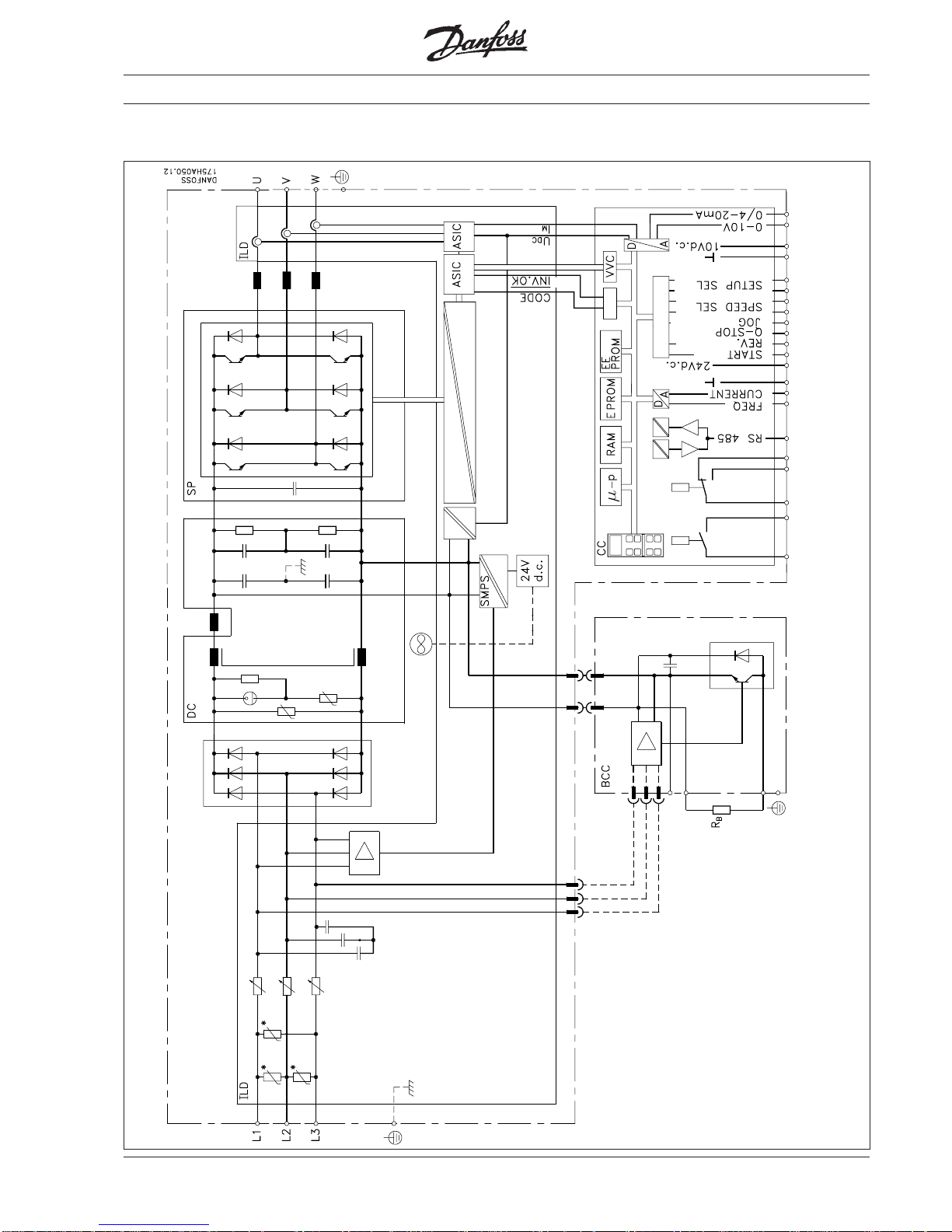
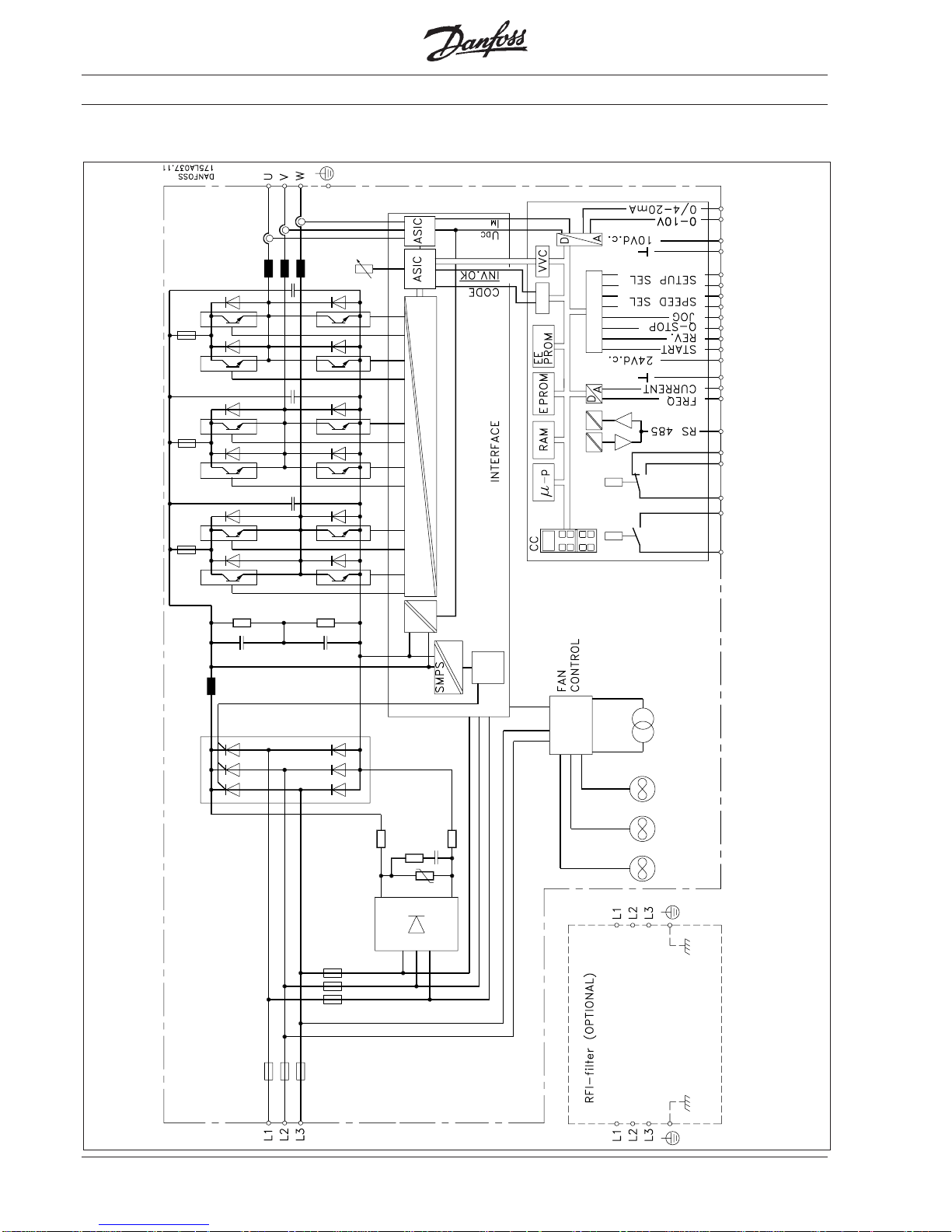
Page 20
20 MG.30.A7.02 - VLT® is a registered Danfoss trademark
Function diagram for VLT® type 3032 - 3052, 220/240 V, VLT® type 3060 - 3075 (380/500 V)
Product range
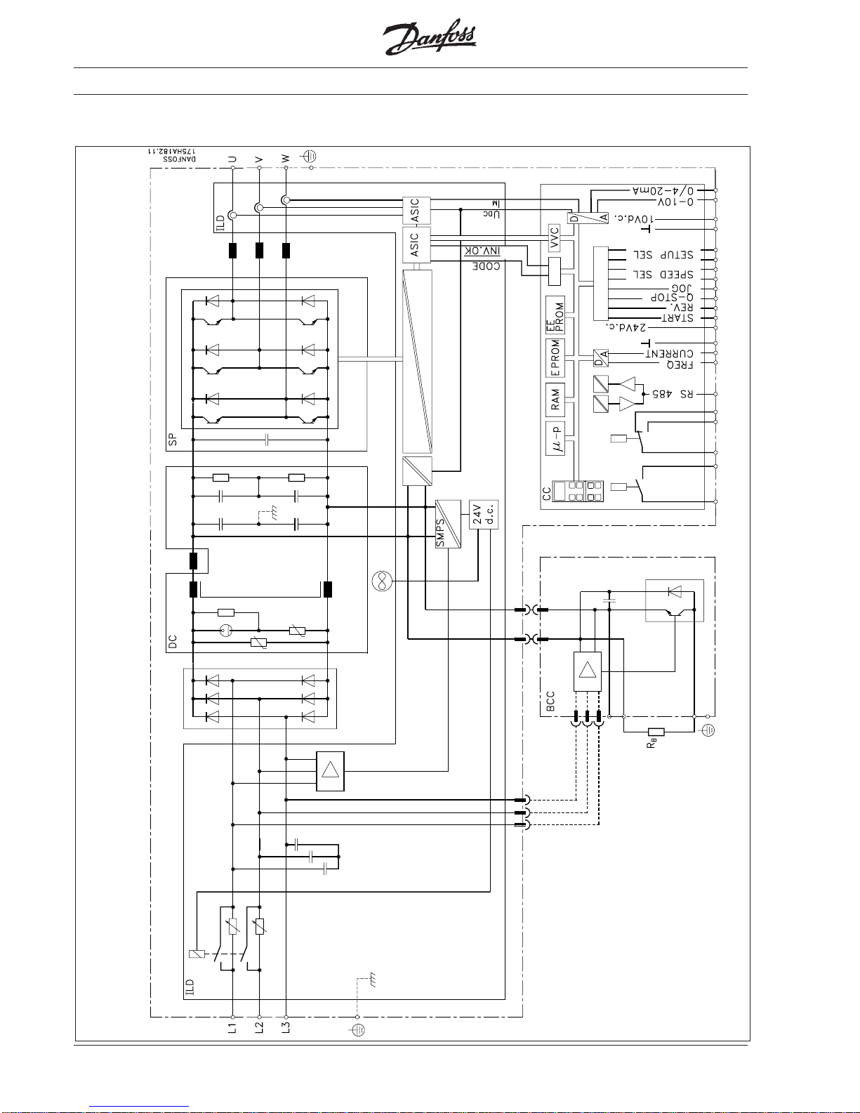
Page 21
21MG.30.A7.02 - VLT® is a registered Danfoss trademark
Function diagram for VLT® type 3100 - 3150 ( 380-500 V)
Product range
Page 22
22 MG.30.A7.02 - VLT® is a registered Danfoss trademark
Function diagram for VLT® type 3200 - 3250 ( 380-500 V)
Product range
Page 23
23MG.30.A7.02 - VLT® is a registered Danfoss trademark
Mains supply 3 x 200/220/230 V and 3 x 220/230/240 V Technical data
According to international VDE and UL/CSA requirements VLT type 3002 3003 3004 3006 3008 3011 3016 3022 3032 3042 3052
Constant torque (CT):
Output current I
VLT,N
[A] 5.4 7.8 10.5 19.0 25.0 32.0 46.0 61.0 80.0 104.0 130.0
I
VLT,MAX
[A] (60 s) 6.7 12.5 17.0 30.0 40.0 51.2 73.6 97.6 120.0 156.0 195.0
Output S
VLT,N
[kVA] 2.1 3.1 4.2 7.6 10.0 12.7 18.3 24.3 31.9 41.4 51.8
S
VLT,MAX
[kVA] (60 s) 2.7 4.9 6.7 12.0 15.9 20.4 29.2 38.9 47.8 62.1 77.7
Typical shaft output P
VLT,N
[kW] 1.1 1.5 2.2 4.0 5.5 7.5 11.0 15.0 22.0 30.0 37.0
Quadratic torque (VT):
Output current I
VLT,N
[A] 5.4 7.8 10.5 25.0 32.0 46.0 61.0 88.0 104.0 130.0 154.0
Output S
VLT,N
[kVA] 1.9 2.9 4.0 10.0 12.7 18.3 24.3 35.1 41.4 51.8 61.3
Typical shaft output P
VLT,N
[kW] 1.1 1.5 2.2 5.5 7.5 11,0 15,0 22.0 33.0 37.0 45.0
Max. cable cross-section [mm2] 2.5 2.5 2.5 16.0 16.0 16.0 35.0 50.0 70.0 70.0 70.0
Max. motor cable length [m] 300, with screened cables: 150 m 300
Output voltage UM [%] 0-100, of mains voltage max. 230 V
Output frequency fM [Hz] 0-120 or 0-500; programmable
Rated motor voltage U
M,N
[V] 200/220/230
Rated motor frequency f
M,N
[Hz] 50/60/87/100
Thermal protection during operation Integrated thermal motor protection (electronic);
thermistor to DIN 44081
Switching on output Unlimited (frequent switching on output may result
in fault message)
Ramp times [s] 0.1 - 3600
VLT type 3002 3003 3004 3006 3008 3011 3016 3022 3032 3042 3052
Max. input current const. load I
L,N
[A] 6.8 9.1 13.3 17.5 22.2 26.4 41.7 52.2 78.0 102.0 128.0
quad. load I
L,N
[A] 6.8 9.1 13.3 23.1 29.6 42.0 56.8 72.3 102.0 128.0 152.0
Max. cable cross-section [mm2] 2.5 2.5 2.5 16.0 16.0 16.0 35.0 50.0 120.0 120.0 120.0
Max. pre-fuses
1)
[A] 16.0 16.0 25.0 40.0 50.0 60.0 80.0 125.0 150.0 150.0 150.0
Supply voltage (VDE 0160) [V] 3 x 200/220/230 ±10% 3 x 220/230/240
Supply frequency [Hz] 50/60
Power factor / cos. ϕ
1
0.9/1.0
Efficiency 0.96 at 100% load
Switching on input times/min. times/min. 2
VLT type 3002 3003 3004 3006 3008 3011 3016 3022 3032 3042 3052
Weight (kg)
IP 007.4 7.4 7.4-------IP 20 - - - 24.0 26.0 32.0 49.0 51.0 - - IP 218.0 8.0 8.0-----143.0 145.0 147.0
IP 54 11.0 11.0 11.0 34.0 37.0 48.0 63.0 65.0 143.0 145.0 147.0
Power loss CT [W] 60.0 100.0 130.0 270.0 425.0 399.0 615.0 935.0 760.0 910.0 1110
at max. load VT [W] 60.0 100.0 130.0 425.0 580.0 651.0 929.0 1350 950.0 1110 1290
Enclosure
VLT type 3002-04: IP 00 / IP 21 / IP 54
VLT type 3006-22: IP 20 / IP 54
VLT type 3032-52: NEMA 1 / 2, IP 21 / 54
Vibration test [g] 0.7
Relative humidity [%] VDE 0160 5.2.1.2.
Ambient temperature (to VDE 0160)
[°C] VLT 3002-3004: -10→ +40, operation at full load
2)
VLT 3006-3052: -10→ +45/40(CT/VT) at full load
2)
[°C] VLT 3002-3004: -30/25→ +65/70, in storage/transport
VLT 3006-3052: -25→ +65/70, in storage/transport
Frequency converter protection Protection against earthing and short-circuiting
Emission EN 55011, EN 55014
EMC standards
EN 50082-2, IEC 1000-4-2, IEC 1000-4-3, IEC 1000-4-4,
(See section “EMC test results”)
Immunity IEC 1000-4-5 VDE 0160, ENV 50140, ENV 50141
+10%+10%
+10%+10%
+10%
-15%-15%
-15%-15%
-15%
1) VLT 3022: Only semi-conductor fuses; VLT 3032-3052: Bussman rapid type JJS built-in (see list)
2) In the range -10 to 0°C, the equipment can start and run; however, the display values and certain operating characteristics will not fulfil the
specifications.
Page 24
24 MG.30.A7.02 - VLT® is a registered Danfoss trademark
Mains supply 3 x 380/400/415 V Technical data
Acc. to international VDE and UL/CSA requirements VLT type 3002 3003 3004 3006 3008 3011 3016 3022 3032 3042 3052
Constant torque (CT):
Output current I
VLT,N
[A] 2.8 4.1 5.6 10.0 13.0 16.0 24.0 32.0 44.0 61.0 73.0
I
VLT,MAX
[A] (60 s) 3.5 6.5 9.0 16.0 20.8 25.6 38.4 51.2 70.4 97.6 117.0
Output S
VLT,N
[kVA] 2.0 2.9 4.0 7.2 9.3 11.5 17.2 23.0 31.6 44.0 52.5
S
VLT,MAX
[kVA] (60 s) 2.5 4.6 6.4 11.5 15.0 18.4 27.6 36.8 50.5 70.2 84.1
Typical shaft output P
VLT,N
[kW] 1.1 1.5 2.2 4.0 5.5 7.5 11.0 15.0 22.0 30.0 37.0
Quadratic torque (VT):
Output current I
VLT,N
[A] 2.8 4.1 5.6 13.0 16.0 24.0 32.0 44.0 61.0 73.0 88.0
Output S
VLT,N
[kVA] 2.0 2.9 4.0 9.3 11.5 17.2 23.0 31.6 44.0 52.5 63.3
Typical shaft output P
VLT,N
[kW] 1.1 1.5 2.2 5.5 7.5 11.0 15.0 22.0 30.0 37.0 45.0
Max. cable cross-section [mm2] 2.5 2.5 2.5 2.5 2.5 16.0 16.0 16.0 35.0 35.0 50.0
Max. motor cable length [m] 300, with screened cables: 150 m
Output voltage UM [%] 0-100, of mains voltage
Output frequency fM [Hz] 0-120 or 0-500; programmable
Rated motor voltage U
M,N
[V] 380/400/415
Rated motor frequency f
M,N
[Hz] 50/60/87/100
Thermal protection during operation
Integrated thermal motor protection (electronic);
thermistor to DIN 44081
Switching on output Unlimited (frequent switching on output may result in fault message)
Ramp times [s] 0.1 - 3600
VLT type 3002 3003 3004 3006 3008 3011 3016 3022 3032 3042 3052
Max. input current const. load I
L,N
[A] 2.8 4.8 7.0 10.0 13.0 13.8 21.8 30.7 41.9 55.6 66.5
quad. load. I
L,N
[A] 2.8 4.8 7.0 13.0 17.0 22.0 31.0 41.5 57.5 66.5 80.0
Max. cable cross-section [mm2] 2.5 2.5 2.5 2.5 2.5 16.0 16.0 16.0 35.0 35.0 50.0
Max. pre-fuses [A] 16.0 16.0 16.0 25.0 25.0 50.0 63.0 63.0 80.0 1001)125
1)
Supply voltage [V] 3 x 380/400/415 ±10% (VDE 0160)
Supply frequency [Hz] 50/60 Hz
Power factor / cos. ϕ
1
0.9/1.0
Efficiency 0,96 at 100% load
Switching on input times/min. 2
VLT type 3002 3003 3004 3006 3008 3011 3016 3022 3032 3042 3052
Weight (kg)
IP 00 7.4 7.4 7.4 12.0 14.0 - - - - - IP 20-----24.0 26.0 32.0 49.0 54.0 54.0
IP 21 8.0 8.0 8.0 13.0 15.0 - - - - - -
IP 54 11.0 11.0 11.0 14.0 15.0 34.0 37.0 48.0 63.0 69.0 69.0
Power loss CT [W] 60 100 130 195 200 270 425 580 880 1390 1875
at m ax. l oad VT [ W] 60 100 130 280 300 425 580 880 1390 1875 2155
Enclosure VLT type 3002-08: IP 00 / IP 21 / IP 54
VLT type 3011-52: IP 20 / IP 54
Vibration test [g] 0.7
Relative humidity [%] VDE 0160 5.2.1.2.
[°C] -10→ +40 -10→ +45/40 (CT/VT)
Ambient temperature operation at full load
2)
at full load
2)
(to VDE 0160) [°C] -25→ +65/70, -25→ +65/70,
in storage/transport in storage/transport
EMC standards Emission EN 55011, EN 55014, EN 61000-3-2
(See section “EMC test results”) Immunity EN 50082-2, IEC 1000-4-2, IEC 1000-4-3, IEC 1000-4-4,
IEC 1000-4-5, VDE 0160, ENV 50140, ENV 50141
1) Only semi-conductor fuses.
2) In the range -10 to 0°C, the equipment can start and run; however, the display values and certain operating characteristics will not fulfil the
specifications.
Page 25
25MG.30.A7.02 - VLT® is a registered Danfoss trademark
Mains supply 3 x 380/400/415 V Technical data
According to international VDE and UL/CSA requirements VLT
type 3060 3075 3100 3125 3150 3200 3250
Constant torque (CT):
Output current I
VLT,N
[A] 86 105 139 168 205 243 302
I
VLT,MAX
[A] (60s) 129 158 209 252 308 365 453
Output S
VLT,N
[kVA] 61.8 73 96 116 142 168 209
S
VLT,MAX
(60s) 89 109 144 175 213 253 314
Typical shaft output P
VLT,N
[kW] 45 55 75 90 110 132 160
Quadratic torque (VT):
Output current I
VLT,N
[A] 105 139 168 205 243 302 368
I
VLT,MAX
[A] (60s) 116 153 185 226 267 332 405
Output S
VLT,N
[kVA] 73 96 116 142 168 209 255
Typical shaft output P
VLT,N
[kW] 55 75 90 110 132 160 200
Max. cable cross-section [mm2] 70 70 150 150 150 2x95 2x95
Max. motor cable length [m] 300
Output voltage UM [%] 0-100 of mains voltage
Output frequency fM [Hz] 0-120 or 0-500, programmable
Rated motor voltage U
M,N
[V] 380/400/415/440/460/500
Rated motor frequency f
M,N
[Hz] 50/60/87/100
Thermal protection during operation Integrated thermal motor protection (electronic);
thermistor to DIN 44081
Switching on output Unlimited (frequent switching on output may result in fault message)
Ramp times [s] 0.1 - 3600
VLT Type 3060 3075 3100 3125 3150 3200 3250
Input current I
L,N
[A] 84.6 103.3 138.4 167.2 201.7 241.9 307.6
I
L,MAX
(60s) [A] 129.0 158.0 209.0 252.0 308.0 365.0 453.0
Quadratic load I
L,N
[A] 103.3 138.4 167.2 201.7 241.9 293.3 366.3
I
L,MAX
(60s) [A] 116.0 153.0 185.0 226.0 267.0 332.0 405.0
Max. cable cross-section [mm2] 120.0 120.0 2 x 120 2 x 120 2 x 120 2 x 240 2 x 240
Pre-fuses
1)
[A] 150.0 150.0 250.0 250.0 300.0 450.0 500.0
Supply voltage (VDE 0160) [V] 3 x 380/400/415/440/460/500 ±10%
Supply frequency [Hz] 50/60
Power factor / cos. ϕ
1
0.9/1.0
Efficiency 0,96 at 100% load
Switching on input times/min. 1
VLT type 3060 3075 3100 3125 3150 3200 3250
Weight (kg)
IP 21 147 147 211 211 220 306 306
IP 54 147 147 211 211 220 306 306
Power loss at max. load CT [W]
Front 423 529 713 910 1091 1503 1812
Heat sink 859 1074 1447 1847 2216 3051 3679
Power loss at max. load VT [W]
Front 529 713 910 1091 1503 1812 2209
Heat sink 1074 1447 1847 2216 3051 3679 4485
Enclosure IP 21 / IP 54 NEMA 1/12
Vibration test [g] 0.7
Relative humidity [%] VDE 0160 5.2.1.2.
Ambient temperature [°C] -10→ +40 operation at full load (VT) -10→ +45 (CT)
2)
(to VDE 0160) [°C] -30/25→ +65/70 in storage/transport
Frequency converter protection Protection against earthing and short-circuiting
EMC standards Emission EN 55011, EN 55014
(See section “EMC test results”) Immunity EN 50082-2, IEC 1000-4-2, IEC 1000-4-3, IEC 1000-4-4,
IEC 1000-4-5, VDE 0160
1) Bussman rapid type JJS integrated.
2) In the range -10 to 0°C, the equipment can start and run; however, the display values and certain operating characteristics will not fulfil the
specifications.
Page 26
26 MG.30.A7.02 - VLT® is a registered Danfoss trademark
Mains supply 3 x 440/460/500 V
Technical data
Acc. to international VDE and UL/CSA requirements VLT type 3002 3003 3004 3006 3008 3011 3016 3022 3032 3042 3052
Constant torque (CT):
Output current I
VLT,N
[A] 2.6 3.4 4.8 8.2 11.1 14.5 21.7 27.9 41.4 54.0 65.0
I
VLT,MAX
[A] (60s) 3.4 5.5 7.7 13.1 17.6 23.2 34.7 44.6 67.2 86.4 104.0
Output S
VLT,N
[kVA] 2.3 2.9 4.1 7.1 9.6 12.6 18.8 24.2 36.0 46.8 56.3
S
VLT,MAX
[kVA] (60s) 2.9 4.7 6.7 11.3 15.2 20.1 30.1 38.6 58.2 7.8 90.1
Typical shaft output P
VLT,N
[kW] 1.1 1.5 2.2 4.0 5.5 7.5 11.0 15.0 22.0 30.0 37.0
Quadratic torque (VT):
Output current I
VLT,N
[A] 2.6 3.4 4.8 8.2 11.1 21.7 27.9 41.4 54.0 65.0 78.0
Output S
VLT,N
[kVA] 1.6 2.9 4.1 7.1 9.6 18.8 24.2 35.9 46.8 56.3 67.5
Typical shaft output P
VLT,N
[kW] 1.1 1.5 2.2 4.0 5.5 11.0 15.0 22.0 30.0 37.0 45.0
Max. cable cross-section [mm2] 2.5 2.5 2.5 2.5 2.5 16.0 16.0 16.0 35.0 35.0 50.0
Max. motor cable length [m] 300, with screened cables: 150 m (3011-3052 in VT: 150 m and 40 m)
Output voltage UM [%] 0-100, of mains voltage
Output frequency fM [Hz] 0-120 eller 0-500, programmable
Rated motor voltage U
M,N
[V] 440/460/500
Rated motor frequency f
M,N
[Hz] 50/60/87/100
Thermal protection during operation Integrated thermal motor protection (electronic); thermistor to DIN 44081
Switching on output Unlimited (frequent switching on output may result in fault message)
Ramp times [s] 0.1 – 3600
VLT type 3002 3003 3004 3006 3008 3011 3016 3022 3032 3042 3052
Max. const. load. [A] 2.6 3.4 4.8 8.2 11.1 12.6 20.1 26.8 37.3 50.2 61.3
input current quadratic load [A] 2.6 3.4 4.8 8.2 11.1 19.6 26.0 34.8 48.6 60.3 72.0
Max. cable cross-section [mm2] 2.5 2.5 2.5 2.5 2.5 16.0 16.0 16.0 35.0 35.0 50.0
Max. pre-fuses [A] 16.0 16.0 16.0 25.0 25.0 30.0 40.0 50.0 60.0 100.01)125.0
1)
Supply voltage (VDE 0160) [V] 3 x 440/460/500 ±10% (VDE 0160)
Supply frequency [Hz] 50/60
Power factor / cos. ϕ
1
0.9/1.0
Efficiency 0.96 at 100% load
Switching on input times/min. 2
VLT type 3002 3003 3004 3006 3008 3011 3016 3022 3032 3042 3052
Weight (kg)
IP 007.47.47.41214 - ---- IP 20 - - - - - 25 26 31 49 54 54
IP 218.08.08.01315 - ---- IP 54 11 11 11 14 15 34 37 48 63 69 69
Power loss at max. load
CT [W] 60 100 130 160 200 174 287 580 958 1125 1467
VT [W] 60 100 130 160 200 281 369 880 1133 1440 1888
Enclosure
VLT type 3002-08: IP 00 / IP 21 / IP 54 VLT type 3011-52: IP 20 /IP54
VLT type 3042-52: IP 20 / IP 54
Vibration test [g] 0.7
Relative humidity [%] VDE 0160 5.2.1.2.
[°C] -10→ +40 -10→ +45/40(CT/VT)
Ambient temperature at full load
2)
at full load
2)
(to VDE 0160) [°C] -25→ +65/70 -25→ +65/70
in storage/transport in storage/transport
Frequency converter protection Protection against earthing and short-circuiting
EMC standards
Emission EN 55011, EN 55014
(See section “EMC test results”)
Immunity EN 50082-2, IEC 1000-4-2, IEC 1000-4-3, IEC 1000-4-4,
IEC 1000-4-5, VDE 0160, ENV 50140, ENV 50141
1) Semi-conductor fuses.
2) In the range -10 to 0°C, the equipment can start and run; however, the display values and certain operating characteristics will not fulfil the specifications.
Page 27
27MG.30.A7.02 - VLT® is a registered Danfoss trademark
Mains supply 3 x 440/460/500 V Technical data
According to international VDE and UL/CSA requirements VLT type 3060 3075 3100 3125 3150 3200 3250
Constant torque (CT):
Output current I
VLT,N
[A] 77 96 124 156 180 240 302
I
VLT,MAX
[A](60s) 116 144 186 234 270 360 453
Output S
VLT,N
[kVA] 67 83 107 135 156 208 262
S
VLT,MAX
(60s) [kVA] 100 125 161 203 234 312 392
Typical shaft output P
VLT,N
[kW] 55 75 90 110 132 160 200
Quadratic torque (VT):
Output current I
VLT,N
[A] 96 124 156 180 240 302 361
I
VLT,MAX
[A](60s) 106 136 172 198 264 332 397
Output S
VLT,N
[kVA] 83 107 135 156 208 262 313
Typical shaft output P
VLT,N
[kW] 75 90 110 132 160 200 250
Max. cable cross-section [mm2] 70 70 150 150 150 2 x 95 2 x 95
Max. motor cable length [m] 300
Output voltage UM [%] 0-100 of mains voltage
Output frequency fM [Hz] 0-120 or 0-500; programmable
Rated motor voltage U
M,N
[V] 380/400/415/440/460/500
Rated motor frequency f
M,N
[Hz] 50/60/87/100
Thermal protection during operation Integrated thermal motor protection (electronic); thermistor
to DIN 44081
Switching on output Unlimited (frequent switching on output may result in fault message)
Ramp times [s] 0.1 - 3600
VLT type 3060 3075 3100 3125 3150 3200 3250
Input current I
L,N
[A] 75.8 94.4 123.4 155.3 177.1 238.9 307.6
I
L,MAX
(60s)[A] 113.7 141.6 185.1 233.0 265.7 358.4 461.4
Quadratic load I
L,N
[A] 94.4 123.4 155.3 177.1 238.9 307.6 359.3
I
L,MAX
(60s)[A] 106.0 136.0 172.0 198.0 264.0 332.0 397.0
Max. cable cross-section [mm2] 120.0 120.0 2 x 120 2 x 120 2 x 120 2 x 240 2 x 240
Max. pre-fuses
1)
[A] 150.0 150.0 250.0 250.0 300.0 450.0 500.0
Supply voltage (VDE 0160) [V] 3 x 380/400/415/440/460/500 ±10%
Supply frequency [Hz] 50/60
Power factor / cos. ϕ
1
0.9/1.0
Efficiency 0.96 at 100% load
Switching on input times/min. 1
VLT type 3060 3075 3100 3125 3150 3200 3250
Weight (kg)
IP 21 147 147 211 211 220 306 306
IP 54 147 147 211 211 220 306 306
Power loss at max. load CT [W]
Front 423 529 713 910 1091 1503 1812
Heat sink 859 1074 1447 1847 2216 3051 3679
Power loss at max. load VT [W]
Front 529 713 910 1091 1503 1812 2209
Heat sink 1074 1447 1847 2216 3051 3679 4485
Enclosure IP 21 / IP 54, NEMA 1/12
Vibration test [g] 0.7
Relative humidity [%] VDE 0160 5.2.1.2.
Ambient temperature [°C] -10→ +40 at full load
2)
(VT) -10→ +45 (CT)
2)
(to VDE 0160) [°C] -30/25→ +65/70 in storage/transport
Frequency converter protection Jord- og kortslutningssikker
EMC standards Emission EN 55011, EN 55014
(See section “EMC test results”) Immunitet EN 50082-2, IEC 1000-4-2, IEC 1000-4-3, IEC 1000-4-4,
IEC 1000-4-5 VDE 0160
1) Bussman rapid type JJS integrated.
2) In the range -10 to 0°C, the equipment can start and run; however, the display values and certain operating characteristics will not fulfil the
specifications.
Page 28
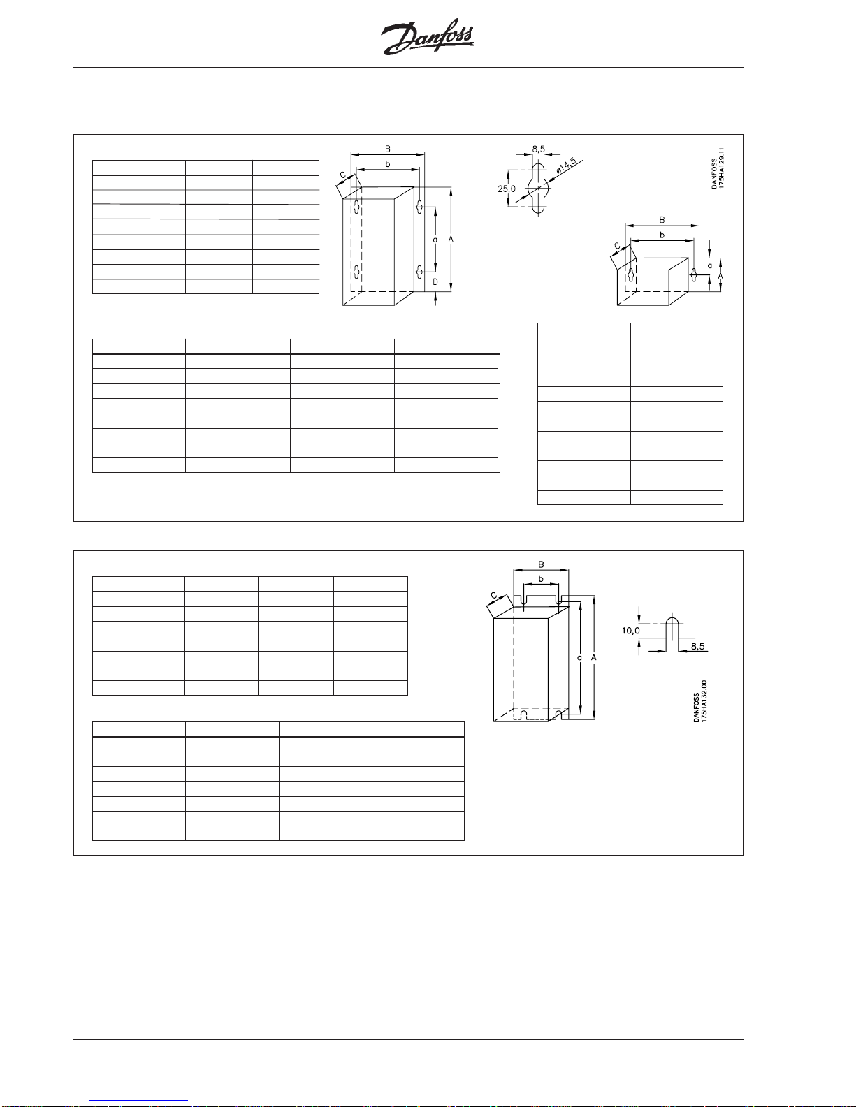
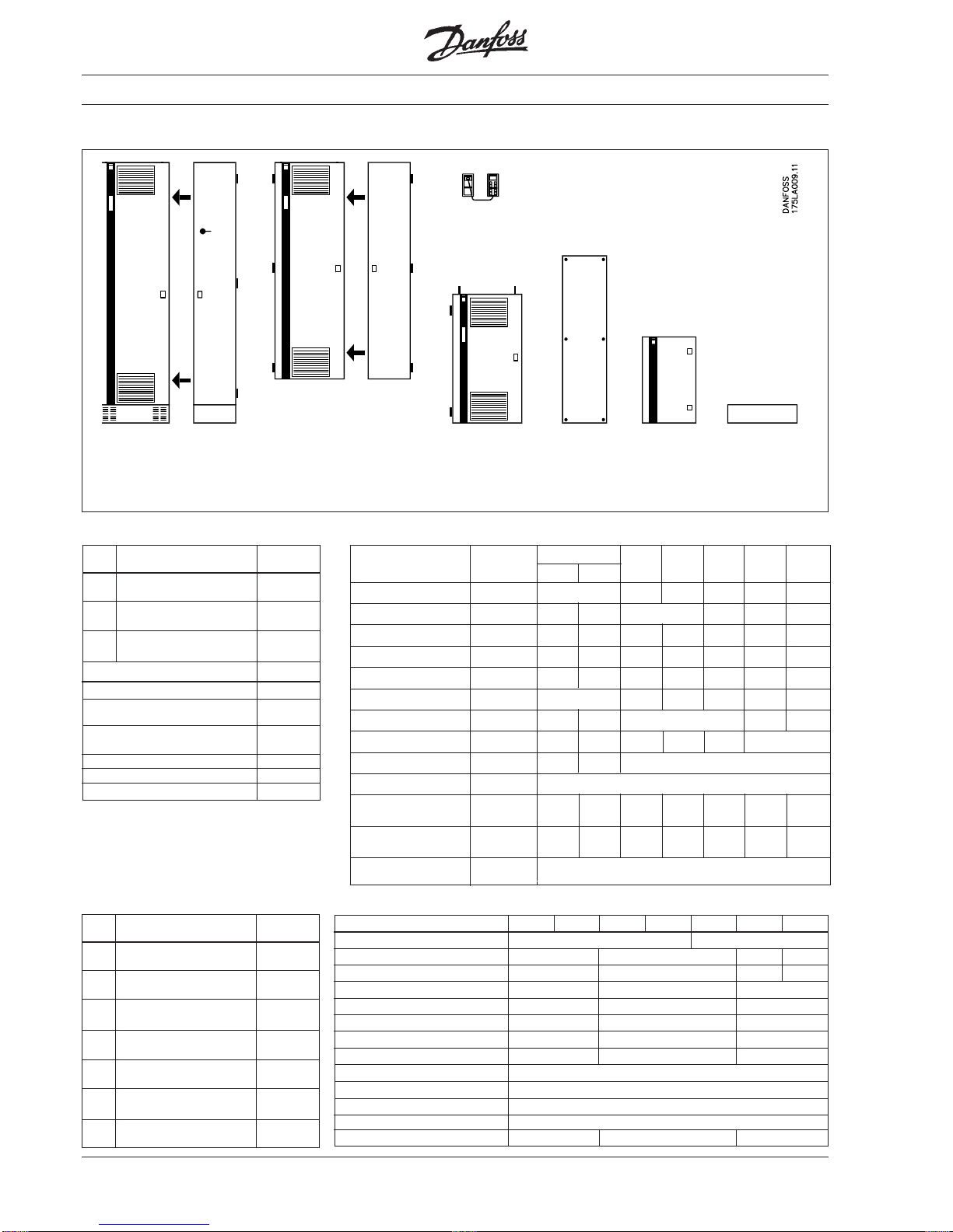
28 MG.30.A7.02 - VLT® is a registered Danfoss trademark
VLT® type 3002-3004 With brake
A (mm) 300 440
B (mm) 281 281
C (mm) 178 178
D (mm) 55 55
a (mm) 191 330
b (mm) 258 258
above/below
(mm) 150 150
left/right (mm) 0 0
Dimensions
IP 00
220 volt
RFI module
RFI-LC filter module
Options LC module
Clamp module
Brake module
A (mm) 115
B (mm) 281
C (mm) 178
D (mm) a (mm) 57.5
b (mm) 258
above/below
(mm) 150
left/right (mm) 0
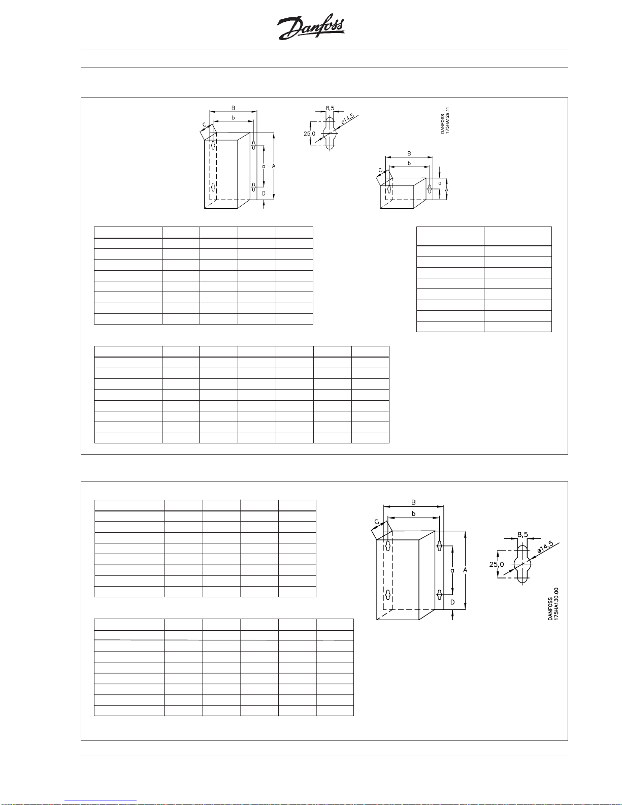
VLT® type 3011-3016 3022 3032-3052
A (mm) 660 780 950
B (mm) 242 242 308
C (mm) 260 260 296
a (mm) 640 760 930
b (mm) 200 200 270
above/below
(mm) 200 200 200
left/right (mm) 0 0 0
IP 20
220 volt
380 / 500 volt
VLT® type 3006-3008 3011 3016-3022
A (mm) 660 780 950
B (mm) 242 242 308
C (mm) 260 260 296
a (mm) 640 760 930
b (mm) 200 200 270
above/below
(mm) 200 200 200
left/right (mm) 0 0 0
VLT® type 3002-04
With brake
3006
With brake
3008
With brake
A (mm) 300 440 440 550 500 610
B (mm) 281 281 281 281 281 281
C (mm) 178 178 178 178 178 178
D (mm) 55 55 55 55 55 55
a (mm) 191 330 330 440 330 440
b (mm) 258 258 258 258 258 258
above/below
(mm) 150 150 150 150 150 150
left/right (mm) 0 0 0 0 0 0
380 / 500 volt
Page 29
29MG.30.A7.02 - VLT® is a registered Danfoss trademark
Dimensions
IP 21
VLT® type 3002-04
With brake
3006
With brake
3008
With brake
A (mm) 360 500 500 610 530 640
B (mm) 281 281 281 281 281 281
C (mm) 178 178 178 178 178 178
D (mm) 85 85 85 85 85 85
a (mm) 191 330 330 440 330 440
b (mm) 258 258 258 258 258 258
above/below (mm)
150 150 150 150 150 150
left/right (mm) 0 0 0 0 0 0
VLT® type 3002-03
With brake
3004
With brake
A (mm) 360 500 390 530
B (mm) 281 281 281 281
C (mm) 178 178 178 178
D (mm) 85 85 85 85
a (mm) 191 330 191 330
b (mm) 258 258 258 258
above/below (mm)
150 150 150 150
left/right (mm) 0 0 0 0
380 / 500 volt
220 volt
RFI module
Brake module
A (mm) 115
B (mm) 281
C (mm) 178
D (mm) a (mm) 57.5
b (mm) 258
above/below
(mm) 150
left/right (mm) 0
Options
IP 54
VLT® type 3002-04 *) 3002-08 3006-08 *) 3011-22 3032-52
A (mm) 530 530 640 810 940
B (mm) 281 281 281 355 400
C (mm) 178 178 178 280 280
D (mm) 85 85 85 70 70
a (mm) 330 330 440 560 690
b (mm) 258 258 258 330 375
above/below
(mm) 150 150 150 150 150
left/right (mm) 0 0 0 0 0
*) With brake
380 / 500 volt
220 volt
VLT® type 3002-04
With brake
3006-11 3016-22
A (mm) 530 530 810 940
B (mm) 281 281 355 400
C (mm) 178 178 280 280
D (mm) 85 85 70 70
a (mm) 330 330 560 690
b (mm) 258 258 330 375
above/below (mm) 150 150 150 150
left/right (mm) 0 0 0 0
Page 30
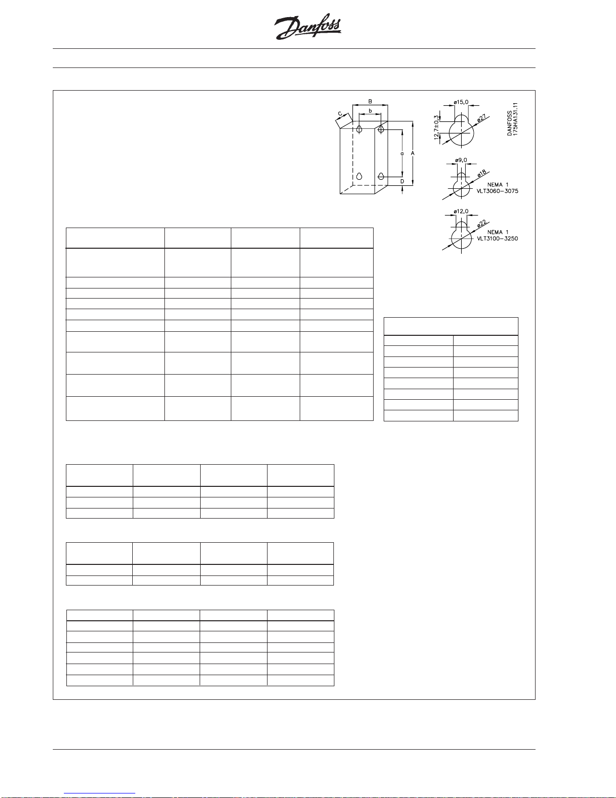
30 MG.30.A7.02 - VLT® is a registered Danfoss trademark
IP 21 / IP 54
Dimensions
RFI module IP21
220 / 230 / 240 / 380 / 500 volt
*) Only limited by hinges on sides.
Note also that the door opens to the left and the option door to the right.
Mounting cabinet IP54
3032-3052, 230 V 3100-3150 3200-3252
3060-3075
A (mm) 900 1515 1695
B (mm) 267 305 349
C (mm) 388 427 554
Internal mounting panel in mounting cabinet IP54
3032-3052, 230 V 3100-3150 3200-3252
3060-3075
A (mm) 845 1459 1640
B (mm) 229 267 311
3060-3075 3100-3150 3200-3252
A (mm) 864 1168 1168
B (mm) 254 317 317
C (mm) 254 254 254
D (mm) 45 52 52
a (mm) 772 1063 1063
b (mm) 174 235 235
VLT® type 3032-3052, 230 V, 3100-3150 3200-3252
3060-3075
A (mm) 954 with ring bolts 1569 with ring bolts 1877 base
1696 with ring bolts and bolts
and optional base
B (mm) 506 with hinges 513 with hinges 513 with hinges
C (mm) IP21 353 394 508
C (mm) IP54 376 417 531
a (mm) 851 1453 placed on base
b (mm) 446 432 placed on base
Floor mounting on base
above (mm) -
230 262
Wall mounting
above/below (mm) 170
230 -
Floor mounting on base
left/right (mm)
- 130 130
Wall mounting
left/right (mm)
*) *) *)
A (mm) 600
B (mm) 380
C (mm) 274
D (mm) 57
a (mm) 485
b (mm) 340
above/below (mm) 80
left/right (mm)
0
Brake module IP54 for VLT
®
3032-3052, 230 V, VLT® 3060-3250
Page 31

31MG.30.A7.02 - VLT® is a registered Danfoss trademark
Control:
Description of terminals
Controls
Terminal 39: Common for analogue/digital outputs
Terminals 42-45: Analogue/digital outputs to display frequency,
reference, current and torque (0-20 mA or 4-20 mA
at max. 470 Ω)/statement of selected status, alarm
or warning (24 V D.C. at min. 600 Ω). See parameters
407 and 408.
Terminal 50: 10 V D.C., max. 17 mA. Supply voltage to
potentiometer and thermistor.
Terminal 53: 0- ±10 V D.C., R
i
= 10 kΩ. Analogue reference input,
voltage. See parameter 412.
Terminal 55: Common for analogue reference inputs.
Terminal 60: 0/4-20 mA, Ri = ~188 Ω.
Analogue reference input, current.
See parameter 413.
Terminal 61: Earth connection, via switch 04, to screen for
communication cable.
See description in parameter group 5.
Terminals 68-69: RS 485 interface. Serial bus communication.
See description of parameter group 5.
Terminal 12: 24 V D.C., max. 140 mA. Supply voltage to digital
inputs (DIN0 - DIN7).
Terminals 16-33: 0/24 V, R
i
= 2 kΩ. < 5 V = logic “0”,
> 10 V = logic “1”. Digital inputs.
See p. 35 and parameters 400-406.
Terminal 20: Common for digital inputs.
Terminal 38: Earth connection to screen for control cables in units
with no terminal clamps for screen.
Terminals 01-03*): Relay output. Max. 250 V A.C., 2 A.
Min. 24 V D.C., 100 mA or 24 V a.c., 100 mA.
See parameter 409.
Terminals 04-05*): Relay output. Max. 250 V A.C., 2 A.
Min. 24 V D.C., 10 mA or 24 V A.C., 100 mA.
See parameter 410.
*) in UL versions: Max. 240 V A.C., 2 A.
NB: On using a thermistor for motor protection, it is connected between terminal 50 and terminal 16
(see description of selection in parameter 400 and outline of thermistor function, page 102).
Page 32

32 MG.30.A7.02 - VLT® is a registered Danfoss trademark
Terminal 16 / par. 400
✭✭
✭✭
✭ Reset Stop *) Freeze reference Thermistor **)
Setup select
Terminal 17 / par. 401 Reset Stop *)
✭✭
✭✭
✭ Freeze ref. Pulse 100 Hz Pulse 1kHz Pulse 10 kHz
Terminal 18 / par. 402
✭✭
✭✭
✭ Start Pulse start No function
Terminal 19 / par. 403
✭✭
✭✭
✭ Reversing Start revers
★★★
) No function
Terminal 27 / par. 404 Quick stop *) DC-brake *) Stop *)
Terminal 29 / par. 405
✭✭
✭✭
✭ Jogging Freeze jogging Freeze reference Digital reference Ramp selection
Terminal 32 / par. 406 Speed up
Speed select Setup select
✭ ✭
✭ ✭
✭ 4
Setup extended
Terminal 33 / par. 406 Speed down
Description of terminals
✭✭
✭✭
✭ Motor
coasting *)
Reset and
motor coasting *)
Cross reference for terminals/parameter functions.
✭✭
✭✭
✭
= Factory setting.
*) Must be with break contact function (NCL), since the function is activated at 0 V on the input.
**) Choose the thermistor function if terminal 50 (10 V
D.C.
) and terminal 16 (parameter 400) are connected.
***) Terminal 19 is pulse start revers if terminal 18 is set to pulse start
Connection examples
The following shows 8 different connection examples with relevant programming suggestions
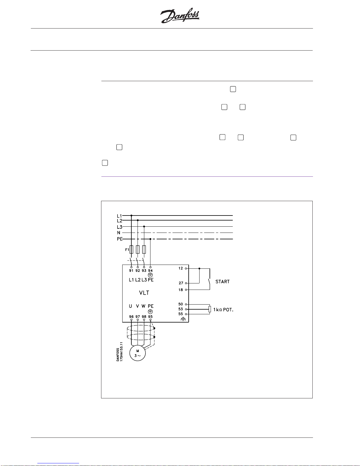
Example 1:
Connection examples
START/STOP REVERSING Reference: 4-20 mA ~ 0-100% speed
NB: Screen for control cables must be
connected as described in the chapter on
EMC-correct installation.
All settings are based on factory settings, but
motor data (parameters 103-105) must be set
according to the motor connected.
Page 33

33MG.30.A7.02 - VLT® is a registered Danfoss trademark
The following must be programmed:
Function Parameter no. Parameter value
0-F
MAX
~ 4-20 mA 407 F
MAX
= 4-20 mA
Ref. 4-20 mA 413 4-20 mA
Connection examples
Example 2:
START/STOP REVERSING, 4-20 mA output signal (0-f
MAX
)
Reference: 4-20 mA ~ 0-100% speed
NB: Screen for control cables must be
connected as described in the chapter on
EMC-correct installation.
All settings are based on factory settings,
but motor data (parameters 103-105) must
be set according to the motor connected.
Page 34

34 MG.30.A7.02 - VLT® is a registered Danfoss trademark
The following must be programmed:
Function Parameter no. Parameter value
Thermistor on terminal 16 400 Thermistor
Connection examples
Example 3:
START/STOP REVERSING, thermistor built-in motor connected to VLT® frequency converter.
Reference: 1 kΩ potentiometer, 0-10 V ~0-100% speed
NB: Screen for control cables must be
connected as described in the chapter on
EMC-correct installation.
All settings are based on factory settings, but
motor data (parameters 103-105) must be set
according to the motor connected
Page 35

35MG.30.A7.02 - VLT® is a registered Danfoss trademark
Connection examples
Example 4:
NB: Screen for control cables must be
connected as described in the chapter on
EMC-correct installation.
All settings are based on factory settings, but
motor data (parameters 103-105) must be set
according to the motor connected.
The following must be programmed:
Function Parameter no. Parameter value
STOP 404 STOP
START 402 Latched START
0-I
MAX
~ 0-20 mA 407 0-I
MAX
Ref. 0-10 V 412 0-10 V
3 conductor START/STOP, 0-20 mA output signal ~ (0-I
MAX
),
0-10 V Reference: ~ 0-100% speed
Page 36

36 MG.30.A7.02 - VLT® is a registered Danfoss trademark
Digital speed up and down
Relay output:
Indication that the output frequency is outside the range 10-45 Hz.
Connection examples
Example 5:
NB: Screen for control cables must be
connected as described in the chapter on
EMC-correct installation.
All settings are based on factory settings, but
motor data (parameters 103-105) must be set
according to the motor connected
The following must be programmed:
Function Parameter no. Parameter value
Speed up and down 401 freeze reference
Speed up and down 406 speed up/down
Frequency warning 409 Frequency
on relay too low
Frequency too low 210(F. low) 10 Hz
Frequency too high 211(F. high) 45 Hz
Warning: On power-up the motor will
restart at the last speed that was maintained for 20 sec.
Page 37

37MG.30.A7.02 - VLT® is a registered Danfoss trademark
6 fixed speeds, max. speed 60 Hz
1 speed = 6 Hz (10%), 2 speeds = 12 Hz (20%),
3 speeds = 18 Hz (30%), 4 speeds = 24 Hz (40%),
5 speeds = 42 Hz (70%), 6 speeds = 60 Hz (100%)
Connection examples
Example 6:
NB: Screen for control cables must be
connected as described in the chapter on
EMC-correct installation.
All settings are based on factory settings, but
motor data (parameters 103-105) must be set
according to the motor connected
The following must be programmed:
Function Parameter no. Parameter value
Setup selection 001 multi setup
Setup selection 400 setup selection
Speed selection 406 digital ref. selection
Select setup 1
Max. frequency 202 60 Hz
Digital reference 1 205 10%
Digital reference 2 206 20%
Digital reference 3 207 30%
Digital reference 4 208 40%
Select setup 2
Max. frequency 202 60 Hz
Digital reference 5 205 70%
Digital reference 6 205 100%
Page 38

38 MG.30.A7.02 - VLT® is a registered Danfoss trademark
Use of the VLT® frequency converter’s internal PID regulator
with internal set-point (digital reference = 50%)
Feedback 0-10 bar ~ 4-20 mA
Min. speed = 10 Hz
Max. speed = 50 Hz
Function Parameter no. Parameter value
Activation of
PID regulator 101 closed loop
Internal setpoint 205 50 %
Feedback type 114 current
Current signal 413 4-20 mA
Min. speed 201 10 Hz
Max. speed 202 50 Hz
Regulator range 120 Depends on
application
Proportional 121 Depends on
amplification application
Integration time 122 Depends on
application
Differentiation time 123 Depends on
application
Example 7:
NB: Screen for control cables must be
connected as described in the chapter on
EMC-correct installation.
All settings are based on factory settings, but
motor data (parameters 103-105) must be set
according to the motor connected
The following must be programmed:
Connection examples
Page 39

39MG.30.A7.02 - VLT® is a registered Danfoss trademark
Function Parameter no. Parameter value
Activation of
PID regulator 101 closed loop
Feedback type 114 current
Current signal 413 4-20 mA
Min. speed 201 10 Hz
Max. speed 202 50 Hz
Regulator range 120 Depends on
application
Proportional 121 Depends on
amplification application
Integration time 122 Depends on
application
Differentiation time 123 Depends on
application
Use of the VLT® frequency converter’s internal PID regulator
with external set-point (0-10 V)
Feedback 0-10 bar ~ 4-20 mA
Min. speed = 10 Hz
Max. speed = 50 Hz
Example 7:
NB: Screen for control cables must be
connected as described in the chapter on
EMC-correct installation.
All settings are based on factory settings, but
motor data (parameters 103-105) must be set
according to the motor connected
Connection examples
The following must be programmed:
Page 40

40 MG.30.A7.02 - VLT® is a registered Danfoss trademark
Warning The VLT® 3000 Series must always be
attached to the wall or floor before further
installation. This rule must be complied
with, particularly with regard to the very
heavy larger VLT
®
types, to avoid injury to
people and equipment.
As an option for VLT® 3100-3150 a base
for floor installation can be supplied (code
nr. 175L3047).
VLT
®
3200-3250 is only intended for floor
installation, and the base is therefore
supplied as part of the VLT®. The base
must be attached to the floor using 4 bolts
before installation of the VLT
®
. The front
panel of the base is unscrewed so that the
VLT
®
can be secured through the 4 top
holes in the base.
See also section on cooling.
Base VLT
®
3100-3250
VLT® 3060-3150 is supplied with a mounting console placed behind the VLT
®
. This
console also serves as an air channel for
the cooling ribs, and on operation the
console must be mounted on the VLT
®
.
The console does not have to be dismantled for installation, but it can be removed
temporarily by loosening the connecting
bolts from the inside of the VLT
®
.
Remember to attach the console again.
Otherwise there is great danger of cut-out
due to overheating.
The 4 drop-shaped holes in the mounting
console make it possible to attach the
fixing bolts to the wall or in the panel
before suspension of the VLT
®
.
The fixing bolts will be accessible through
the top and bottom of the console to
facilitate tightening.
VLT
®
3060-3075 is only for wall
installation.
VLT
®
3100-3150 is supplied for wall
installation as standard.
The VLT® 3000 Series can be installed with flanges side by side
VLT® 3060-3250
Mechanical installation
The VLT® 3000 Series is cooled by natural
convection. Therefore air must be able to
pass freely under and above the unit.
VLT
®
3002-3052
This series must be installed on a flat
surface so that the air flow can follow the
cooling ribs right from the bottom of the
VLT
®
. The VLT® with fixing holes in the side
flanges can be installed with flange against
flange. The VLT
®
without side flanges has
fixing holes in top and base (IP 20) and can
be installed without side spacing.
See also section on cooling.
General
Page 41

41MG.30.A7.02 - VLT® is a registered Danfoss trademark
Mechanical installation
VLT® type 3100-3150 3200-3250
A [mm] 79 102
B [mm] 153 178
a [mm] 23 10
b [mm] 191 287
Base for mounting console and IP 54, RFI module:
VLT® type 3100-3150 3200-3250
A [mm] 76 100
B [mm] 151 176
a [mm] 23 10
b [mm] 191 287
Base:
Base seen from side:
previous versions of VLT® 3100-3250
units, but never use the previous base
design for the VLT
®
units with the remov-
able base plate.
The bases for VLT® and options have been
updated to match VLT® 3100-3250 with
the removable plate in the bottom. Note
that the ventilation slots have been replaced with two apertures in the sides.
When a base is also used for the mounting
console and RFI in IP 54 enclosure,
remember to match up the ventilation
apertures.
The new base design can be used with
VLT® type 3100-3150 3200-3250
A [mm] 127 127
B [mm] 495 495
C [mm] 361 495
D [mm] 4 x 12.7 4 x 12.7
b [mm] 445 445
c [mm] 310 445
The drawing shows the base and its
dimensions.
Page 42

42 MG.30.A7.02 - VLT® is a registered Danfoss trademark
Mechanical installation
The front door to VLT® 3032-3052, 230 V,
and VLT
®
3060-3250 has hinges on the
left-hand side.
The table below shows the door radius
and the distance necessary from the
installation surface to be able to open the
door without difficulty.
VLT® 3032-3052, 230 V,
VLT
®
3060-3250
VLT-type 3032-52, 230 V, 3100 3125 3150 3200 3250
3060 3075
C [mm] 846 846 894 894 894 1008 1008
R [mm] 505 505 513 513 513 513 513
It is recommended that the cables be lead
through the base, but the sides can also
be used.
The plate in the right-hand side of the
VLT
®
enclosure can be removed, and the
hole can be used for cable lead-through if
an extra enclosure or an IP 54 RFI module
is required. If one of these modules is to
be used, the right-hand side of the VLT
®
enclosure may not be bored for other
cables.
The VLT® enclosure is made of steel. To
avoid metal flakes flying into the VLT®’s
electronics, cable holes should not be
bored until the unit has been vertically
installed.
The drawing below shows the VLT
®
types
3060-3250 seen from the bottom with the
removable base plate.
VLT® types 3002-3008, 400/500 V, and
VLT® 3002-3004, 200 V, with IP 54 enclosure have a plastic base with holes
marked for cable unions.
Note that for the above VLT®s for 200 V
and 500 V (UL-approved) a metallic
bonding plate is included in the plastic
base. The metal plate is used to terminate
cable conductor or armouring. See the
information on p. 148 concerning connection of the bonding plate when IP 00 VLT
®
s
are converted to IP 21 enclosure with UL
approval.
The cable unions mechanically support the
cables for IP 21/54 enclosure. For the
IP 00 version, the cables must be relieved
by other means (cable stirrups). The
cables end in removable plugs.
VLT® 3011-3052, 400/500 V, and VLT
®
3006-3022, 200 V, have a metal base with
cut-outs for cable lead-through.
The bottom of the VLT® types 3032-3052,
230 V, and VLT® types 3060-3250 has a
plate mounted with 6 cross-head screws.
The plate can be removed to ease installation of the cable unions. After cable leadthrough has been completed, the plate
must be screwed back in place to ensure
correct IP enclosure grade and cooling.
Cable access:
Page 43

43MG.30.A7.02 - VLT® is a registered Danfoss trademark
To enable the VLT® to get rid of the
cooling air, there must be a free air space
both above and below the VLT®. The
minimum spacing requirements depend
on the VLT
®
type and enclosure.
Cooling
See the dimensioning tables.
The following applies to VLT
®
types 3002-
3052:
The following applies to VLT® types 3060-3150 with wall installation:
Enclosure grade A
IP 00 100 mm
IP 21 100 mm
IP 20 200 mm
IP 54 150 mm
Model 3002-3052
Note that the VLT®s can be installed
without side spacing, but it must be
possible to move the hinges freely.
The following applies to VLT
®
types 3100-3250 with floor installation:
Model A B
3100-3150 230 130
3200-3250 260 130
Note! The side spacing to the next VLT
®
must be 130 mm due to the base’s air
intake on the side.
VLT® types 3060-3250 are equipped with
a fan in the front door to cool the internal
components. A distance permitting free
opening of the door is sufficient in front of
the VLT
®
. See the section: “Door radius
VLT® 3060-3250”.
Mechanical installation
Model A B
3060-3075 170 25
3100-3150 230 25
Page 44

44 MG.30.A7.02 - VLT® is a registered Danfoss trademark
The tables on pp. 25-29 show the output
loss P2(W) from the VLT® 3000. The
maximum cooling air temperature t
IN,MAX
is
40° C at 100% load (of rated value).
Mechanical installation
Heat emission from
the VLT® 3000
1. Add up the values of PΦ for all the
VLT®’s to be installed in the same panel.
The highest cooling air temperature (tIN)
occurring must be lower than t
IN,MAX
(40° C).
The day/night average must be 5° C
lower (VDE 160).
The outlet temperature of the cooling air
may not exceed: t
OUT,MAX
(45° C).
2. Calculate the permitted temperature
difference between the cooling air
temperature (t
IN
) and the cooling air
outlet temperature (t
OUT
): ∆t = 45° C-t
IN
= 1388 m3/h
5
2240 x 3.1
1. ∑P
Φ
= 8x PΦ W = t
IN, MAX
= 2240 W.
2. ∆t = 45°C-tIN = 45°C-40°C= = 5°K.
2. Quantity of air (at 40°C) =
Example:
Ventilation of VLT® units
when panel-mounted
The quantity of air needed to cool the
VLT
®
frequency converters can be calcu-
lated as follows:
The total output loss and the total air
requirement at 100% load for 8 VLT
®
type
3006 units mounted in the same panel.
Cooling air temperature (t
IN
) = 40° C and
max. cooling air outlet temperature
(t
OUT,MAX
) = 45° C.
P
Φ
= 280 W and t
IN, MAX
= 40° C.
3. Calculate the necessary quantity of air
in m
3
/h =
The outlet from the fan must be located
above the highest mounted frequency
converter.
Remember to take pressure drops over
filters into account and that the pressure
decreases as the filters are choked.
∑PΦx 3.1
∆t
Insert ∆t in Kelvin
Page 45

45MG.30.A7.02 - VLT® is a registered Danfoss trademark
The VLT®’s voltage is dangerous when it is
connected to the mains supply and for up
to 14 minutes after disconnection of the
VLT
®
. Electrical installation may therefore
only be carried out by an authorized technician.
Warning Incorrect installation of the motor or VLT
®
can damage equipment and cause
serious injury or death. Therefore comply
with the instructions in this manual, as
well as local and national safety regulations.
Note:
It is the responsibility of the user or
technician to ensure correct earthing and
protection according to current local and
national standards.
Pre-fuses
General
The terminals for the 3-phase supply and
the motor are placed in the lowest section
of the VLT
®
’s enclosure.
The motor cable’s screen is connected to
both the VLT® and the motor. The VLT
®
has been tested with a given length of
screened cable and a particular crosssection. If the cross-section is increased,
the capacitance leakage of the cable
increases and thereby the discharge
current. The length must be reduced
For VLT
®
types 3002-3052, external prefuses must be installed in the current
supply to the frequency converter.
The technical data section on pp. 23-27
states correct size and dimensioning.
For VLT
®
types 3032-3052, 230 V, and
VLT® types 3060-3250, pre-fuses are
included in the VLT®’s mains connection.
proportionally. The electronic thermal relay
(ETR) in UL-approved VLT
®
frequency
converters is UL-approved for singlemotor application when parameter 315 is
set at trip, parameter 311 at “0 sec.” and
parameter 107 programmed for the
motor’s nominal current (read on the
motor’s type plate).
Electrical installation
A high voltage test can be performed by
short-circuiting terminals U, V, W, L1, L2,
L
3
, and impressing 2.5 kW D.C. for 1
second between this short circuit and the
chassis.
After the high voltage test, the filter condensers should be discharged using a
resistor of e.g. 100 ohm, 1/4 W- 1/2 W.
The resistors is placed between +D.C. bus
to the chassis and -D.C. bus to the chassis, for a few seconds.
High voltage test
Error voltage relays, or neutral earthing,
current in the discharged current.
Any ELCB relays used must comply with
local regulations.
The relays must be suitable to protect 3phase equipment with bridge rectifier and
short discharge on power-up.
See also the section on discharge currents
on p. 128.
Extra protection
Page 46

46 MG.30.A7.02 - VLT® is a registered Danfoss trademark
Connection of VLT
®
Mains and motor
connection for
VLT
®
types 3002-3052
The max. cable cross-section and equivalent max. length and terminal size are
shown in the technical data section, pp.
25-29.
The mains supply and the motor are
connected in accordance with the drawing
below.
Mains Motor
Page 47

47MG.30.A7.02 - VLT® is a registered Danfoss trademark
VLT® type 3032-3052, 230 V, 3060-3075
Cable sizes See technical data
Cable end, type Screw terminal
Terminal torque [Nm] 31.1
Cable sizes See technical data
Cable end, type M6 Bolt
Terminal torque [Nm] 6
Bussmann type
Motor
Input
Fuses*
*) Note: With the above fuses, VLT
®
types 3060-3075 have a short-circuiting capacity of
100,000 A.
Mains and motor
connection for
VLT
®
types 3032-3052,
230 V, and VLT® types
3060-3075
JJS 150
150 A/600 V
Connection of VLT
®
Page 48

48 MG.30.A7.02 - VLT® is a registered Danfoss trademark
Motor
Input
Fuses*
VLT® type 3100 3125 3150
Cable sizes See technical data See technical data See technical data
Screw terminal Screw terminal Screw terminal
31.1 31.1 31.1
Cable sizes See technical data See technical data See technical data
M10 Bolt M10 Bolt M10 Bolt
10 10 10
Bussmann type
Cable end,
type
Terminal torque
[Nm]
Cable end,
type
Terminal torque
[Nm]
JJS 250
250 A/600 V
JJS 250
250 A/600 V
JJS 300
300 A/600 V
*) Note: With the above fuses, VLT
®
types 3100-3150 have a short-circuiting capacity of
100,000 A.
Mains and motor
connection for
VLT
®
types
3100-3150
Connection of VLT
®
Page 49

49MG.30.A7.02 - VLT® is a registered Danfoss trademark
*) Note: With the above fuses, VLT® types 3100-3150 have a short-circuiting capacity of
100,000 A.
VLT® type 3200 3250
Cable sizes See technical data See technical data
Cable end, type Screw terminal Screw terminal
Terminal torque [Nm] 42 42
Cable sizes See technical data See technical data
Cable end, type M8 Bolt M8 Bolt
Terminal torque [Nm] 6 6
Bussmann type
Motor
Input
Fuses*
JJS 450
450 A/600 V
JJS 500
500 A/600 V
Mains and motor
connection for
VLT
®
types
3200-3250
Connection of VLT
®
Page 50

50 MG.30.A7.02 - VLT® is a registered Danfoss trademark
With the VLT® 3000 Series, all types of
3-phase asynchronous standard motors
can be used.
In general, small motors (220/380 V, ∆/ )
are star-connected. Large motors are
delta-connected (380/660 V, ∆/ ).
Motor connection
The factory setting will give clockwise
rotation when the output of the VLT
®
3000
Series is connected as follows:
Terminal 96 connected with U phase
Terminal 97 connected with V phase
Terminal 98 connected with W phase
The rotation direction can be changed by
swapping the two motor cable phases.
With the VLT® 3000 Series controls, the
rotation direction can also be changed
using the “reverse” function.
VLT® 3000 Series can control several
motors connected in parallel. If the motor
speeds must be different, motors of
different rated speeds must be applied.
The motor speed can be changed simultaneously and the ratio between the rated
motor speeds is maintained in the whole
range.
The total current consumed by the motors
may not exceed the maximum rated output
current I
VLT,N
of the VLT® 3000 Series.
If motor sizes deviate considerably, problems may arise during start and at low
speed. This is due to the fact that small
motors have a relatively high ohmic resistance in the stator, and therefore they
require more start voltage during start and
at low speed.
In systems with parallel motor operation,
the internal overcurrent protection cannot
be used as motor protection for the individual motor, since the output current must
be programmed for the total motor current.
Additional motor protection should therefore be used, e.g. thermistors in each
motor (or individual thermal relay).
Direction of rotation
Parallel connection
of motors
Connection of motor
Y
Y
Page 51

51MG.30.A7.02 - VLT® is a registered Danfoss trademark
EMC installation
The purpose of CE-labelling is to avoid
technical obstacles to trade within EFTA
and the EU. The EU has introduced the
CE-label as a simple way of showing
whether a product complies with the
relevant EU directives. The CE-label says
nothing about the quality or specifications
of a product. Three EU directives relate to
frequency converters:
The machine directive (89/392/EEC)
All machines with critical, moving parts are
comprised by the machine directive which
came into force on 1 January 1995. Since
a frequency converter is largely electrical
by function, it does not fall under the
machine directive. However, if a frequency
converter is supplied for use in a machine,
we provide information about the safety
aspects relating to the frequency converter. We do that by means of a manufacturer’s declaration.
The low-voltage directive (73/23/EEC)
Frequency converters must be CE-labelled
in accordance with the low-voltage directive, which will come into force on
1 January 1997.
This directive applies to all electrical
equipment and appliances used in the
voltage range of 50-1000 VAC and 751500 VDC.
The EMC directive (89/336/EEC)
EMC is short for electromagnetic compatibility. The presence of electromagnetic
compatibility means that the mutual
interference between different components/appliances is so small that the
functioning of the appliances is not affected. The EMC directive comes into
force on 1 January 1996. The directive
distinguishes between components,
appliances, systems and installations.
The EU “Guidelines on the Application of
Council Directive 89/336/EEC” outline four
typical situations of using a frequency
converter. For each of these situations,
explanations are offered as to whether the
situation in question is covered by the
EMC directive and must be CE-labelled.
1. The frequency converter is sold direct
to the end-user. This applies for example if the frequency converter is sold to
a DIY-market. The end-user is not an
expert. He installs the frequency
converter himself, e.g. for controlling a
hobby machine or a domestic appliance. This frequency converter must
be CE-labelled in accordance with the
EMC directive.
2. The frequency converter is intended for
use in a complete product. It is sold
e.g. to a professional machine builder
who has the technical knowledge it
takes to install the frequency converter
correctly. The frequency converter
need not be CE-labelled in accordance
with the EMC directive. Instead, the
frequency converter manufacturer must
be provide detailed guidelines on how
to carry out an EMC-correct installation.
3. The frequency converter is intended for
use in an installation built up on the site
of use by a professional. This could be
e.g. a complete installation for manufacturing purposes or for the generation of heat/ventilation. The installation
is planned and made by a professional
installation builder. The complete
system is not to be CE-labelled in
accordance with the EMC directive.
The system must comply with the basic
requirements contained in the directive.
This is ensured by using components,
appliances and systems which are CElabelled in accordance with the EMC
directive.
4. The frequency converter is sold as part
of a complete system, such as an airconditioning system. The complete
system must be CE-labelled in accordance with the EMC directive.
What is CE-labelling?
Page 52

52 MG.30.A7.02 - VLT® is a registered Danfoss trademark
EMC installation
Danfoss VLT
®
frequency converter
and CE-labelling
CE-labelling is a positive feature when
used for it original purpose, i.e. to facilitate
trade within the EU and EFTA.
However, CE-labelling may cover many
different specifications. This means that it
has to be checked what a given CE-label
specifically covers.
The specifications covered can in fact be
widely different. That is why the CE-label
can give installers a false feeling of security when using a frequency converter as a
component in a system or an appliance.
We CE-label our VLT frequency converters in accordance with the low-voltage
directive. This means that as long as the
frequency converter is installed correctly,
we guarantee that it complies with the
low-voltage directive. We issue a declaration of conformity confirming that our CElabel complies with the low-voltage directive.
The CE-label also applies to the EMC
directive on the condition that the EMCcorrect installation and filtering instructions in the manual have been
followed. On this basis a conformity
declaration is issued in accordance with
the EMC directive.
To help ensure that your installation is
EMC-correct, the manual provides detailed instructions for installation. Furthermore, we specify which norms that are
complied with by our products.
We offer the filters that meet the specifications and can gladly provide other types of
assistance that can help you obtain the
best possible EMC result.
Page 53

53MG.30.A7.02 - VLT® is a registered Danfoss trademark
EMC installation
In support of our claim that the VLT
®
frequency converter complies with the
protection requirements for emission and
immunity under EMC directive 89/336/
EEC, a Technical Construction File (TCF)
has been prepared for each model. Such
a file defines the EMC requirements and
the measurements made in accordance
with harmonised EMC standards in a
Power Drive System (PDS) that consists of
a VLT
®
frequency converter, a control
cable and the controls (control box), motor
cable and motor plus any options added.
The Technical Construction File is prepared on this basis in cooperation with an
authorised EMC laboratory (Competent
Body).
In most cases the VLT frequency converter is used by professionals of the trade
as a complex component forming part of a
larger appliance, system or installation. It
must be noted that the responsibility for
the final EMC properties of the appliance,
system or installation rests with the fitter.
As an aid to the fitter, Danfoss has prepared EMC installation guidelines for the
Power Drive System. The standards and
testing levels stated for the Power Drive
System are complied with, provided that
the EMC-correct installation guidelines are
applied.
The following basic issues need to be
considered when installing a frequency
converter, so as to obtain electromagnetic
compatibility (EMC).
Safety earthing:
Please note: The frequency converter has
a high leakage current and must be
earthed appropriately for safety reasons.
Apply local safety regulations.
High-frequency earthing:
Keep the earth wire connections as short
as possible.
Connect the different earth systems at the
lowest possible conductor impedance.
The lowest possible conductor impedance
is obtained by keeping the conductor as
short as possible and by using the greatest possible surface area. A flat conductor,
for example, has a lower HF impedance
than a round conductor for the same
conductor square value.
If more than one appliance is installed in
cabinets, the cabinet rear plate, which
must be made of metal, should be used as
a common earth reference plate. The
metal cabinets of the different appliances
are mounted on the cabinet rear plate
using the lowest possible HF impedance.
This avoids having different HF voltages
for the individual appliances and avoids
the risk of radio interference currents
running in connection cables that may be
used between the appliances.
In order to obtain a low HF impedance,
use the fastening bolts of the appliances
as HF connection to the rear plate. It is
necessary to remove insulating paint or
similar from the fastening points.
The control cable and the filtered mains
cable should be installed separately from
the motor and brake cables to prevent
interference coupling. Normally, a distance
of 20 cm will be sufficient, but it is recommended to keep the greatest possible
distance wherever possible, especially
where cables are installed in parallel over a
substantial distance. (Seperation should
increase in proportion).
With respect to sensitive signal cables,
such as telephone cables and data cables,
the greatest possible distance is recommended with a minimum of 1 m per 5 m of
power cable (mains, motor and brake
cable). It must be pointed out that the
necessary distance depends on the sensitivity of the installation and the signal
cables, and that therefore no precise
values can be stated.
If cable clamps are used, sensitive signal
cables are not to be placed in the same
cable clamps as the motor cable or brake
cable.
If signal cables are to cross power cables,
this should be done at an angle of 90
degrees.
Remember that all noisy in- or outgoing
cables to/from a cabinet should be
screened or filtered.
Cables
Earthing
Compliance with EMC
directive 89/336/EEC
Screened cables
The screen must be a low HF-impedance
screem. This is ensured by using a braided
screen of cobber, aluminium or iron.
Screen armour intended for mechanical
protection, for example, is not suitable for
an EMC-correct installation.
Page 54

54 MG.30.A7.02 - VLT® is a registered Danfoss trademark
Electrical interference from the cable
network, cable-borne interference, 150
kHz-30 MHz, and airborne interference
from the drive system, 30 MHz-1 GHz, is
for frequencies under approx. 50 MHz
produced in particular by the inverter, the
motor cable and the motor system.
As the sketch below shows, capacitive
currents in the motor cable together with
high du/dt from the motor voltage will
produce interference.
Use of screened motor cable increases
the leakage current I, (see fig. below). This
is because screened cables have higher
capacitance to earth than unscreened
cables. If the leakage current is not filtered, it will cause greater interference on
the mains in the radio leakage range under
approx. 5 MHz. Since the leakage current
I
1
is carried back to units through the
screen (I4), in principle this will give only a
small electromagnetic field from the
screened motor cable, according to the
figure below.
EMC installation
Radio interference
in general
The screen reduces the radiated interference, but increases the low frequency
interference on the mains. With a mains
filter, the interference level on the mains
will be reduced to around the same level
for both screened and unscreened cables.
The motor cable screen must be connected to the VLT
®
’s enclosure as well as
the motor enclosure. The best way to do
this is to use screen clamps to avoid unr
ravelled screen ends. These increase the
screen impedance at higher frequencies,
which reduces the screen effect and
increases the interference current (I
4
).
When screened cable is used for
PROFIBUS, control cable, signal interface
and brake, the screen must be mounted on
the enclosure at both ends. In certain
situations, however, it will be necessary to
break the screen to avoid current loops.
In cases where the screen must be placed
on a mounting panel for the VLT
®
frequency converter, the mounting panel
must be of metal because the screen
currents must be led back to the unit. It is
also important to ensure good electrical
contact from the mounting screws through
the mounting curve to the VLT
®
frequency
converter.
With regard to installation, it is generally
less complicated to use unscreened
cables than screened cables. To observe
the EN55011-1A requirements to radiated
interference (30MHz-1GHz) a motor filter
must be installed when using
unscreened
cables.
In order the reduce the interference level
from the system overall (unit + installation)
as far as possible, it is important to make
motor and brake cables as short as
possible.
Cables with a sensitive signal level may
not be led together with motor and brake
cables.
Radio interference higher than 50 MHz
(airborne) will be particularly affected by
the control electronics.
Page 55

55MG.30.A7.02 - VLT® is a registered Danfoss trademark
Instructions for
installation
Filtering
Electrical interference from the cable
network - cable-borne as well as air-borne
- can be prevented by using the correct
filters. The filters or equivalent stated in
the product programme must be installed,
and when re-mounting, the filter
installation instructions are to be
observed.
VLT
®
3002-3052
All models have filters for integration into/
mounting on the appliance itself. Some
models offer the feature of ordering the
appliance with the filter already integrated.
See the product range. In the case of
subsequent installation, the instructions for
installation of the filter must be complied
with (see also the instructions for installation, item F).
VLT
®
3060-3250
The filter is supplied as an IP54 option or
an IP20 option that cannot be integrated in
the appliance itself, but can be bolted
directly on the side.
Mechanical installation
VLT® 3002-3008, IP00/IP21 enclosure
VLT® 3002-3008, IP00/IP21/IP54
enclosure with brake:
VLT® 3002 - VLT® 3008, IP00/IP21 enclosure and VLT® 3002-3008, IP00/IP21/IP54
enclosure with brake must always be installed against a conductive rear plate.
Install the metal cabinet of the VLT
®
frequency converter up against the rear
plate. The rear plate must be electrically
conductive and act as a common HF earth
reference for the VLT
®
frequency converter, the RFI/brake module and any
brake cables used. The VLT® frequency
converter and the RFI/brake module must
be installed with the lowest possible HF
impedance to the rear plate. This can best
be done through the fastening bolts for the
enclosure (see instructions for installation,
pp. 57-59, item A). Since the aluminium
enclosure of the appliances is anodised
and thus electrically insulating, toothed
(serrated) washers should be used to
penetrate the anodisation - or the anodised surface has to be removed. Remember also to remove any varnish or paint
from the rear plate.
VLT
®
3002-3008, IP54 enclosure without
brake
VLT
®
3011-3052, IP20/IP54 enclosure:
Appliances can be installed on an electrically conductive or a non-conductive rear
plate, since the RFI filter can be or is
integrated and the screen from control
cables, motor cable and brake cable (not
VLT
®
3002-3008) can be terminated in the
appliances (see instructions for installation,
pp. 57-59, items B, C and D).
If an electrically conductive rear plate is
used, the VLT® frequency converter must
be installed with the lowest possible HF
impedance to the rear plate, and the
instructions for installation, pp. 57-59,
items A, B, C, D and E, must be complied
with.
If a non-conductive rear plate is used (i.e.
in the case of installation directly against a
brick wall), use the instructions for installation, pp. 57-59, items B, C and D.
VLT
®
3032-3052 200V and
VLT
®
3060-3250 380-500V, IP20 RFI option
See further examples of installation on
page 59.
- The filter should be installed on the
same panel as the frequency converter.
The panel must be electrically conductive. Both the frequency converter and
the filter must have a good highfrequency connection to the panel.
- The filter should be connected as close
as possible to the frequency converter
input, the maximum distance being 1
metre.
- The mains filter should be earthed at
both ends.
- Before mounting the filter on the panel,
remove any surface treatment, etc.
NB! The filter must be earthed before
connection to mains.
VLT
®
3032-3052 200V and
VLT® 3060-3250 380-500V, IP54 RFI
module
See further examples of installation on
page 59.
1. Remove the wire plate and the Philips
screw in the right-hand side of the
VLT® 3000 (save the screws for the
wire plate for later use).
2. Place the IP54 RFI option in the righthand side of the VLT
®
3000.
3. Before fastening the RFI option to the
VLT® 3000, place the accompanying
gasket and mount it around the cable
inlet to maintain the IP54 enclosure
grade.
4. Fasten and earth the RFI module to the
VLT® 3000 with 2 screws plus screw
washers. With the RFI module door
open, mount the two screws and
fasten the module.
5. Use the screws from item 1) to fasten
and seal off the wire inlet between the
RFI option and the VLT
®
3000.
6. Using the wire net supplied with the
RFI option, connect the RFI filter to the
VLT
®
3000 AC mains input and earth.
7. Connect the AC mains input and earth
to the terminals placed at the top of the
RFI filter.
EMC installation
Page 56

56 MG.30.A7.02 - VLT® is a registered Danfoss trademark
EMC installation
Motor cable
In order to comply with the EMC specifications concerning emission and immunity, the motor cable must be screened
unless otherwise stated for the mains filter
in question. It is important to keep the
motor cable as short as possible so as to
reduce the interference level and the
leakage currents to a minimum.
The motor cable screen should be connected to the metal cabinet of the frequency converter and to the metal casing
of the motor. Screen connections should
be made using as large a surface as
possible. (See the instructions for installation, pp. 57-59, item D). The motor cable
screen should basically not be broken and
not be earthed in the process. If it becomes necessary to break the screen to
install a motor isolator or motor relays, the
screen should be continued at the lowest
possible HF impedance.
Using filters 175H7083 and 175H7084, the
VLT
®
3002-3008 complies with EN550111A using an unscreened motor cable. In
addition to reducing the mains interference, the filters also reduce the interference radiating from the unscreened motor
cable. As far as the motor cable is concerned, only interference above 30MHz is
reduced (see EN55011-1A).
Control cables
Control cables should be screened. The
screen should be connected using a
clamp to the VLT
®
frequency converter
base (see the instructions for installation,
pp. 57-59, item C). Normally, the screen
should also be connected to the base of
the controlling appliance (follow the
instructions for use of the appliance in
question).
In connection with very long control cables
and analogue signals, 50 Hz ripple loops
may occur in rare cases, depending on the
installation. This is because of interference
coupling from the mains supply cables. In
this connection it can be necessary to
break the screen or possible insert a 100 nF
condenser between screen and base.
Cable for serial
communication
The cable for serial communication should
be screened.
The screen should be installed using a
clamp on the VLT
®
frequency converter
(see the instructions for installation, pp. 5759, item B).
With regard to cable specifications and
instructions for installation in general,
reference is made to the PROFIBUS
product manual.
trolling appliance. They can be avoided by
making a tight fit with the cabinet base
rear plate, thereby ensuring that any
equalising currents will run via the base
rear plates and their joints, not via the
cable screens.
Efforts should be made to avoid possible
equalising currents that may occur when
the control cable screen is connected to
the base (earthed) at both ends. Equalising
currents occur because of voltage differences between the VLT
®
frequency
converter base and the base of the con-
Equalising currents
Brake cables
If a brake module is used, the cable to the
brake resistor must be screened. In the
case of VLT 3002 - VLT 3008, connect the
screen to the conductive rear plate, on
which the VLT frequency converter has
been mounted. If VLT 3011 - VLT 3052 are
used, mount the screen by means of a
special union. In the case of VLT 3060 VLT 3250, where the brake module is a
separate module in its own casing, it is
possible to use special unions or to
terminate the screen in the conventional
way. All sizes of unit require the screen to
be connected to the brake resistor
casing.
Page 57

57MG.30.A7.02 - VLT® is a registered Danfoss trademark
EMC installation
VLT 3002-3008
VLT 3011-3052
Hole size Cable ø Screen ø Danfoss code No.
PG 21 17.0 - 20.0 12.5 - 17.5 175H2882
PG 29 22.0 - 26.0 15.0 - 21.0 175H2883
PG 36 30.0 - 32.0 24.0 - 30.0 175H2884
Page 58

58 MG.30.A7.02 - VLT® is a registered Danfoss trademark
EMC installation
VLT 3060-3250
Page 59

59MG.30.A7.02 - VLT® is a registered Danfoss trademark
VLT 3032-3052 200V.
3060-3075 400/500V.
EMC installation
VLT 3100-3150
VLT 3200-3250
Page 60

60 MG.30.A7.02 - VLT® is a registered Danfoss trademark
The control panel for programming and
local control and information is placed on
the front of the frequency converter.
The control panel consists of a keyboard
and a display.
The keyboard is used for two purposes:
local operation and programming.
The display is used for communication
between the frequency converter and
the operator.
On the control panel you will see a red
and a green LED.
When the green LED (On) lights up, there is
voltage to the frequency converter.
The red LED (Alarm) is used for alarm
indications.
In an ALARM MODE the LED will flash.
Using an optional adaptor and cable, the
control panel can be mounted in a cabinet
cover. The maximum distance between the
frequency converter and the remote box is 3
m.
The enclosure of the adapter (front) is IP 54.
Minimum panel aperture: 112 x 51 mm
± 0.5 mm.
The control panel
Keys for programming
Programming is carried out by changing
the data values of parameters grouped in
a menu.
Some parameters can have different
settings in four separate setup functions
(parameter 001). See p. 81 for more
information. is used to find (select) the
parameter to be changed.
Menu
is used to enter MENU MODE from
either DATA MODE or DISPLAY MODE.
Menu
is also used to enter a specific group of
parameters.
Data
is used to enter DATA MODE or DIS-
PLAY MODE from MENU MODE.
Data
is
also used to move the cursor between data
values.
+
and–are used to select a group of
parameters, a specific parameter or a data
value.
From any status you can enter DISPLAY
MODE by pressing
Menu
and
Data
at the same
time.
Menu
Data
+
–
External mounting
of the control panel
(remote box)
In normal operation (in DISPLAY MODE)
+
and–are used to scroll between 12 display read-outs:
• Reference %
• Frequency Hz
• Display / Feedback %
• Current A
• Torque %
• Power kW
• Power HP
• Energy kWh
• Motor voltage V
• D.C. voltage V
• Motor load therm. %
• Inverter load therm %
Parameters 003/004 are used for local
reference setting.
Jog
is used to run the motor at a fixed pre-
programmed frequency (parameter 203).
Fwd.
Rev.
➤
➤
is used to change direction.
Note: For safety reasons the key can only
be activated when the frequency converter
is set for local operation (parameter 003),
and the functions
Jog
and
Fwd.
Rev.
➤
➤
must be se-
lected in parameters 008 and 009.
Keys for local operation
Start
Stop
Reset
Fwd.
Rev.
➤
➤
Jog
+
–
Control panel
Menu
Page 61

61MG.30.A7.02 - VLT® is a registered Danfoss trademark
Different modes,
different information
See the list of status, reset and alarm messages on page 122.
See the list of parameters on pages
151-152.
00.0 Hz
FREQUENCY ➜
FUNCTION OK 1
RESET MODE
REASON FOR ALARM
SET DATA VALUE
FLASHING PARAMETER NUMBER
0.. =
FLASHING CURSOR
STATUS, including indication of local operation
NAME OF SELECTED DISPLAY READ-OUT
SELECTED DISPLAY READ-OUT, including unit
ACTIVE SETUP
SELECTION
(1-4 CAN BE SELECTED
IN PARAMETER 001)
PARAMETER NAME
NAME
FLASHING PARAMETER NUMBER
0.. =
FLASHING CURSOR
E=
FLASHING CURSOR
SET DATA VALUE
ROTATION DIRECTION
PARAMETER GROUP
PARAMETER NAME
00.0 Hz
0.. OPERATING
SETTING
00.0 Hz
00 0 LANGUAGE
ENGLISH 1
00.0 Hz
LANGUAGE
E NGLISH 1
The display will give you different information, depending on the mode and the
operation setting.
DISPLAY MODE
MENU MODE
PARAMETER MODE
DATA MODE
ALARM MODE
ALARM
TRIPPED
OVERVOLTAGE
Display layout
Page 62

62 MG.30.A7.02 - VLT® is a registered Danfoss trademark
How the display looks in the four modes
Display layout
Page 63

63MG.30.A7.02 - VLT® is a registered Danfoss trademark
Initialization is used to return to a known
initial status (factory setting).
This requirement arises on change of
software version, if so many of the parameters have been changed that the
situation is no longer clear, or if the VLT
®
is
Initialization
General
behaving strangely and cannot be reset in
the normal way.
Fundamentally, initialization takes place in
two ways:
(Press the keys MENU + DATA + JOG
simultaneously with mains connection until
“init eeprom” is shown in the third line).
This method is used on:
• Replacement of software version.
This results in:
• First time setup of communication
parameters to ensure factory setting.
(These parameters are set
from the unit’s operating panel):
Standard
(RS 485) 500 Address
501 Baud Rate
Profibus 820 Baud Rate
821 FMS/DP select
822 Station Delay
904 PPO Write
918 Station Address
• Reset of operation data (para. 600) and
fault memory (para. 602)
• Initialization of all other parameters as de-
scribed under initialization via parameter
604
Manual initialization
Initialization via
parameter 604
This method is used on:
• Initialization of all parameters to factory
setting, except for:Communication
parameters (para. 500 and 501) and
the aforementioned Profibus parameters if this option is installed.
Operation data (para. 600)
Fault memory (para. 602)
NB! If only factory setting of data in a
single setup is required, ”Factory set” can
be selected in para. 001.
In para. 002 this setting is copied to the
chosen setup.
Page 64

64 MG.30.A7.02 - VLT® is a registered Danfoss trademark
“LOCK” switch
There is a way to avoid unwanted programming. It is done by opening the
switch pin 01 on the control card.
Time out
Local reference (parameter 004) is not left
automatically after 20 seconds.
The display is a three-line LCD display.
Line A is used to display operator read-
outs. It will show the value corresponding
to the setting in DISPLAY MODE.
The selected value will remain in the
display line during programming of parameters.
Line B displays information on parameters,
direction, and re-set status.
Line C displays information on status and
setup or data value.
The software automatically leaves DATA
MODE after 20 seconds if no operation is
recorded.
By pressing
Data
once, it is possible to
return to DATA MODE and program the
parameter which was left after 20 sec.
Display layout
Avoid unwanted data change
Page 65

65MG.30.A7.02 - VLT® is a registered Danfoss trademark
Please note: You have to press
Stop
Reset
to stop
the motor before changing the data values
of some parameters (see factory settings).
Menu build-up
The frequency converter has a menu system with several parameters to be used to
optimise your motor operation.
The parameters are divided into 7 groups
(group 0 - group 6).
There are also groups for different options.
They are described in guidelines for each
option.
Parameter grouping
0.. Operation and display 000-099
1.. Load and motor 100-199
2.. References and limits 200-299
3.. Functions and timers 300-399
4.. Inputs and outputs 400-499
5.. Serial data interface 500-599
6.. Service and diagnosis 600-699
The parameter number is made up of three
digits.
The digit on the left indicates the group.
Parameter
numbering
Travelling through
the menu
After the first power-up you will find the
frequency converter in DISPLAY MODE.
Changing group
If you want to travel through the menu, use
the key
Menu
followed by the keys+or
–
(see page 61).
Changing a parameter number
You can enter the parameters of the
selected group with the key
Menu
followed
by+or–.
+
increases and–decreases the
parameter number.
Menu build-up
When you have chosen a parameter and
want to change its data value, press the
Data
key followed by the +or–key.
The data value can be a digit or a text.
Data value of a
parameter
Changing a data value:
digit
When you have pressed
Data
the digit to the
right will be active and be shown flashing.
The other digits can be activated one by
one by pressing
Data
one, two or three times.
The activated digit can be changed by
pressing+or–.
Changing a data value:
text
If the data value of the chosen parameter
is a text, the display shows the selected
text.This can be changed by pressing
Data
and then+or–. All options are then
shown one by one. The text shown in the
display will be stored at the same moment
you leave DATA MODE.
You are storing the data value by pressing
Menu
. Now you have activated the parameter number and can travel through the
group of parameters again using+and–.
Leaving DATA mode
Within each group the parameters are
numbered, starting with 0.
For example, in group 1..: 100, 101, 102....
A new data value is stored on leaving
DATA MODE, or automatically after 20
seconds.
Please note: You have to press
Stop
Reset
to stop
the motor before changing the data values
of some parameters (see factory settings).
Page 66

66 MG.30.A7.02 - VLT® is a registered Danfoss trademark
Group description
Note: The choice between the 12 different
display read-outs mentioned on page 60 is
not an element of this group.
Load and motor
Group 1..
Operation and display
Group 0..
In this group you will find parameters
concerning the display read-out, local
operation and setup handling.
This group of parameters has been reser-ved for the adjustments necessary to
adapt the VLT
®
frequency converter to the
application and motor.
The preprogrammed values in parameters
100-105 are suitable for normal application
using standard asynchronous motors with
constant torque load without parallelcoupled motors.
If quadratic torque load is applied, select
one of the VT (variable torque) modes or VT
modes with CT starting torque (high breakaway torque).
Parallel-coupled motors:
If parallel-coupled motors or any synchronous type of motor are used at the output
from a VLT
®
frequency converter, constant
torque is selected without start compensation in parameter 100, and open-loop speed
control is selected in parameter 101.
Auto-optimization:
An additional tuning might improve the
torque yield or speed accuracy, if the motor
data differ from the typical values assumed
as default.
Items 1-4 in Quick setup must be carried out
first.
The adaptive tuning facility offers you an
easy way to perform that tuning. Initiate
the tuning by setting parameter 106 to
"ON" and pressing
Start
.
The VLT® will perform a test measurement
of vital motor data and automatically adjust
the appropriate parameters (108-113).
For optimum adjustment automatic parameter tuning on a cold motor is recommended.
Caution: the motor will start running without
warning.
Manual tuning is possible in parameters
109-113 for correction of default or automatically tuned values.
Closed loop
If closed loop control is required the transmitter, tachometer or encoder should supply one of the standard analogue signals
(e.g. 0-10 V, 0-20 mA; 4-20 mA) or a pulse
signal frequency of max. 100 Hz, 1 kHz or
10 kHz (programmable).
The full-scale value is always 100%.
The transmitter signal should be selected
to utilise the full scale range as far as
possible, but with due allowance for overshooting.
The pulse signal has an over-shooting
range of up to 200% for the 100 Hz and
1 kHz signals, and up to 130% for the
10 kHz signal.
To optimise dynamics and accuracy an impulse frequency as close to 10 kHz as possible should be selected (at max.
motor speed).
If this is not possible, the transmitter signal
can be corrected by the feedback scaling
factor (parameter 125).
The equivalent reference signal can either
be fixed internally (digital reference) or supplied via standard analogue signals or the
pulse signal (range 0-100%). It is not possible to select the same type of signal (voltage, current, pulses) for both the reference
and the feedback.
At start the output frequency is determined
by the frequency converter’s reference and
the feed forward factor and the min/max
frequency settings. The feed forward factor
is used to set the steady state output frequency.
Feedback scaling is used if the transmitter
cannot be optimally selected for the input
signals’ scale range.
The PID regulator then adjusts the output
frequency by comparing reference and
feedback.
At stop the controller output (integrator) is
set to 0 so that a restart follows the normal
start situation.
Continued...
Page 67

67MG.30.A7.02 - VLT® is a registered Danfoss trademark
Group description
Load and motors
Group 1..
(continued)
PID optimisation
Parameter 121
(proportional gain) is set for 0.01
(min. value, factory setting).
Parameter 122
(integration time) is set for infinite
(max. value, factory setting).
Parameter 123
(differentiation time) is set for 0 sec.
1. Start the frequency converter.
2. Increase the value in parameter 121
(proportional amplification) until the
feedback signal (FB) oscillates
constantly. Reduce the value until the
oscillation ceases. Reduce further
(0.4-0.6 times).
3. Reduce the value in parameter 122
(integration time) until the feedback
signal (FB) oscillates again. Increase
the value until the oscillation ceases.
Then increase further 1.15-1.5 times.
4. Parameter 123 (differentiation time) is
only used in fast systems. The typical
value is the integration time divided
by 4.
5. Reduce control range if necessary
(parameter 120) to reduce overshooting.
Note:
The drive should be started / stopped
repeatedly to ensure stability.
Page 68

68 MG.30.A7.02 - VLT® is a registered Danfoss trademark
Load and motor, group 1..
(continued)
Open loop control
Group description
Page 69

69MG.30.A7.02 - VLT® is a registered Danfoss trademark
Load and motor, group 1..
(continued)
Closed loop control
Group description
Page 70

70 MG.30.A7.02 - VLT® is a registered Danfoss trademark
The brake control for the electromechanical brake features functions which among
other things improve positioning.
The brake control features an optimized
relay function with a short reaction time, to
control the electromechanical brake.
The brake must be active (without voltage)
while the unit is running idle. Relay 01/04
can be programmed so that the motor
brake is released automatically when the
programmed motor frequency is exceeded.
It is possible to set separate ramp-up
(start) and ramp-down (stop), cut-out and
cut-in frequencies.
Groups
Introduction
Brake control
The motor current monitoring features a
function which automatically activates the
brake when the motor current drops to or
below the programmed minimum value.
It is possible to override motor current
monitoring during start-up. How long it is
to be inactive depends on the delay
setting.
To achieve high dynamics, start compensation is deselected in parameter 100.
The parameters for brake control are
described below:
Para. 100 Data value [6]
Para. 230-231232-233 See drawing below
Para. 409/410 Data value [16][17]
Start/Stop
Frequency/Current
Relay
Programming of
ramp-up and rampdown times
In parameter 405 (terminal 29 input), two
different ramp times can be selected.
For normal start/stop, either ramp 1 or 2
can be selected.
Quick stop is always ramp 2.
WARNING:
The parameters for the relay used for
brake control must not be changed
(para. 409 or 410) as this can cause the
brake to be released and thus damage
equipment or endanger human life.
Page 71

71MG.30.A7.02 - VLT® is a registered Danfoss trademark
The VLT® frequency converter distinguishes between different types of references.
Note that the analogue reference type is
Inside / outside range
References and limits
Group 2..
Analogue reference
(parameter 411)
Digital reference type
(parameter 204) Relative reference Data [1]
1. Linear between min. and max. Data [0]
2 .Proportional to reference with min.
and max. limitation. Data [1]
3. Proportional to reference with reversing.
Data [2]
programmed in group 4...
Unused references are set at 0, or
switched out (parameters 205-208, 412-
413).
frequency converter can be programmed
to give output signals if the limits are
exceeded (parameters 407-410).
Frequency and current range
In this group you can define a range within
which you want your motor to run. The
Group description
Page 72

72 MG.30.A7.02 - VLT® is a registered Danfoss trademark
This group includes a parameter called
“flying start”.
This function tells the frequency converter
how to handle a motor with a rotating
shaft.
: Flying start
: Normal start
: Dont care
Example 1: Example 2: Example 3: Example 4:
Condition fulfilled
(see page 108-109)
Function of the "flying start" when selected:
Data 13/14 Data 19/20 Data 25/26
Data 15/16 Data 21/22 Data 0/12
Data 17/18 Data 23/24
The analogue output signals on terminals 42/45 set in parameters 407/408.
Group description
The analogue output signals and the
relays can be used for different types of
indication.
See parameters 407 and 408.
Group 4.. is used to program other
configurations of the terminals than the
default configuration.
See the configuration of the digital input
signals on page 32.
Inputs and outputs
Group 4..
Functions and timers,
Group 3..
Page 73

73MG.30.A7.02 - VLT® is a registered Danfoss trademark
Serial data interface
Group 5..
The serial bus communicates using RS
485 (terminals 68 and 69). It is possible to
read and set the parameters of the VLT
®
frequency converter, and to give it reference and control commands. The serial port
can be used by up to 31 VLT
®
frequency converters per master without using a repeater. If 3 repeaters are used,
up to 99 VLT
®
frequency converters can be
connec-ted to one master.
It is important to connect and terminate the
serial bus with the correct impedance to
avoid any reflections which may disturb the
cable’s data transmission.
This adjustment can take place by setting
the 03.1 and 03.2 switches in the “on” position (see p. 148) in the last VLT
®
frequency
converter connected to the serial BUS.
Communication takes place by means of a
protocol specified by Danfoss.
The data format consists of 10 bits: one
start bit (logically 0), eight data bits, and one
stop bit (logically 1). There is no parity
check. Set the baud rate (speed of transmission) in parameter 501 and the address of each unit in parameter 500.
Telegram format / protocol
The communication protocol for the VLT
®
3000 Series consists of a 22-byte telegram
using ASCII characters. These characters
make it possible to operate, set and read
parameters, and to receive status feedback from the VLT
®
frequency converter.
Communication takes place in the following
way: The master sends a telegram to a
VLT
®
frequency converter. Then the master
awaits a reply from that frequency converter before sending a new message.
The reply to the master is a copy of the
telegram sent by the master, now
containing any updated data values and
the status of the VLT
®
frequency converter.
Data format
Telegram format
Continued...
Group description
Page 74

74 MG.30.A7.02 - VLT® is a registered Danfoss trademark
Serial data interface
Group 5..
(continued)
Byte 1:
Start byte which in this case must be the
character ”<” (ASCII: 60).
Bytes 2 and 3:
The two-digit address of the frequency
converter with which communication is
required. This address is also programmed
in parameter 500.
Sending to address 00 means broadcast
to all units connected to the bus. None of
the units will reply, but they will carry out the
command.
Byte 4:
Control parameter telling the VLT
®
frequency converter what to do with the
following data values.
U (update) means that the data value
(bytes 13-19) must be read into the
frequency converter’s parameter (bytes
9-13).
R (read) means that the master wants to
read the data value of the parameter
stated in bytes 9-12.
C (control) means that the frequency converter reads only the four command bytes
(5-8) and returns with status. Parameter
number and data value will be ignored.
I (read index) means that the frequency
converter reads index and parameter, and
returns with status.
Parameter is stated in bytes 9-12 and
index is stated in bytes 13-18.
Parameters with indices are read-only
parameters. Action will be taken on the control word.
Two-dimensional indices (x,y) (parameters
601 and 602) are separated by a comma,
see byte 19.
Example:
Index = x, y
Data value = 013,05
Byte 14-18 = 013 05
Byte 19 = 2
Group description
Bytes 5-8:
Control and status words are used to send
commands to the frequency converter and
to send status from frequency converter to
master.
Bytes 9-12:
In these bytes the parameter number is set.
Bytes 13:
Used for the sign before data value in
bytes 14-18. All characters other than "−"
are taken as "+".
Bytes 14-18:
Here is placed the data value of the parameter stated in bytes 9-12.
The value must be a whole number. If a
decimal point is needed it is stated in byte
19.
Note: Some data values have square brackets with a number, e.g. [0]. Use this number
instead of the "text" data value.
Bytes 19:
The position of the decimal point in the data
value stated in bytes 14-18. The number
states the number of characters after the
decimal point.
Byte 19 can then be 0, 1, 2, 3, 4 or 5.
For example, the number 23.75 is stated:
Byte no. 13 14 15 16 17 18 19
ASCII character + 2 3 7 5 0 3
If byte 19 = 9 in the response telegram see
table page 80.
Bytes 20, 21:
Used for counter control from byte 2 up to
and including 19. The decimal values of the
ASCII characters are added and reduced to
the two “low” characters, e.g. Σ 235 [ ]
reduced = 35. If no control is necessary cancel the function with “?” (ASCII: 63) in the
two bytes.
Byte 22:
Stop byte stating the end of the telegram.
The character ”>” is used (ASCII: 62).
Page 75

75MG.30.A7.02 - VLT® is a registered Danfoss trademark
According to the data format, 1 byte
consists of 8 data bits, but in the control
word only the 4 least significant bits of
each byte are used, so that ASCII characters from A to 0 can be used. The table
below shows the significance of the individual bits of the control word:
Control words, bytes 5-8 in the telegram
The control word is used to send control
commands from a master (e.g. a PC) to
the VLT
®
frequency converter.
Serial data interface,
group 5.. (continued)
Groups
Bit 00, OFF1/ON1:
Ordinary ramp stop which uses the ramp
time in parameter 215/216. Bit 00 = “0”
means stop, bit 00 = “1” means that the
frequency converter can start if the other
start conditions are fulfilled.
Bit 01, OFF2/ON2:
Free-wheeling stop. Bit 01 = “0” means
free-wheeling stop, bit 01 = “1” means that
the frequency converter can start if the
other start conditions are fulfilled.
Bit 02, OFF3/ON3:
Quick stop, which uses the ramp time in
parameter 218. Bit 02 = “0” means quick
stop, bit 02 = “1” means that the frequency
converter can start if the other start conditions are fulfilled.
Bit 03, Free-wheeling/possible:
Free-wheeling stop. Bit 03 = “0” means
stop, bit 03 = “1” means that the frequency
converter can start if the other start conditions are fulfilled. Note: In parameter 503 it
is selected how bit 03 is connected (gates)
with the equivalent function on the digital
inputs.
Bit 04, Quick stop/ramp:
Quick stop, which uses the ramp time in
parameter 218. Bit 04 = “0” means quick
stop, bit 04 = “1” means that the frequency
converter can start if the other start conditions are fulfilled.
@
A
B
C
D
E
F
G
H
I
J
K
L
M
N
O
P
ASCII
0
/
1
X = Dont care, if P is used in a group of 4 bits, current status is retained. Only the groups with the characters in P are
activated. Bit 10 = 0 signifies no change from current status.
15 14 13 12 11 10 09 08 07 06 05 04 03 02 01 00
0000000000000000
0001000100010001
0010001000100010
0011001100110011
0100010001000100
0101010101010101
0110011001100110
0111011101110111
1000100010001000
1001100110011001
1010101010101010
1011101110111011
1100110011001100
1101110111011101
1110111011101110
1111111111111111
XXXXXXXXXXXXXXXX
Byte 8 Byte 7 Byte 6 Byte 5
N
O
F
U
C
T
T
I
O
N
/
R
E
V
E
R
S
I
N
G
S
E
L
E
C
T
S
E
T
U
P
1
N
O
F
U
C
T
T
I
O
N
/
C
A
T
C
H
U
P
N
O
F
U
C
T
T
I
O
N
/
S
L
O
W
D
O
W
N
D
A
T
A
N
O
T
V
A
L
I
D
/
V
A
L
I
D
J
O
G
2
O
F
F
/
O
N
J
O
G
1
O
F
F
/
O
N
N
O
F
U
C
T
T
I
O
N
/
R
E
S
E
T
R
A
M
P
S
T
O
P
/
S
T
A
R
T
H
O
L
D
R
A
M
P
P
O
S
S
I
B
L
E
Q
U
I
C
K
S
T
O
P
R
A
M
P
F
R
E
E
W
H
E
E
L
P
O
S
S.
O
F
F
3
/
O
N
3
O
F
F
2
/
O
N
2
O
F
F
1
/
O
N
1
Control word
S
E
L
E
C
T
S
E
T
U
P
2
Page 76

76 MG.30.A7.02 - VLT® is a registered Danfoss trademark
Groups
The function of bit 04 can be redefined to
D.C. brake in parameter 514. Otherwise
the function is as described above. Note: In
parameter 504/505 it is selected how bit 04
is connected (gates) with the equivalent
function on the digital inputs.
Bit 05, Hold/ramp possible:
Ordinary ramp stop which uses the ramp
time in parameter 215/216. Bit 05 = “0”
means stop, bit 05 = ”1” means that the
frequency converter can start if the other
start conditions are fulfilled.
Bit 06, Ramp stop/start:
Ordinary ramp stop which uses the ramp
time in parameter 215/216. Bit 06 = “0”
means stop, bit 06 = “1” means that the
frequency converter can start if the other
start conditions are fulfilled. Note: In parameter 506 it is selected how bit 06 is connected (gates) with the equivalent function
on the digital inputs.
Bit 07, No function/reset:
Reset of trip. Bit 07 = “0” means no reset,
bit 07 = “1” means reset of a trip. Note: In
parameter 508 it is selected how bit 07 is
connected (gates) with the equivalent
function on the digital inputs.
Bit 08, JOG 1 OFF/ON:
Activation of preprogrammed speed in
parameter 511 (Bus JOG 1). JOG 1 is only
possible when bit 04 = “0” and bit 00-03
= “1”.
Bit 09, JOG 2 OFF/ON:
Activation of preprogrammed speed in
parameter 512 (Bus JOG 2). JOG 2 is only
possible when bit 04 = “0” and bit 00-03 =
“1”. If both JOG 1 and JOG 2 are activated
(bit 08 and 09 = “1”), JOG has highest priority, i.e. the speed programmed in parameter 511 is used.
Bit 10, Data not valid/valid:
Used to tell the VLT
®
frequency converter
whether the control word must be used or
ignored. Bit 10 = “0” means that the control
word is ignored. Bit 10 = “1” means that the
control word is used. This function is relevant because the control word is always
contained in the telegram, no matter which
telegram type is used (see byte 4 in ”telegram format”), i.e. it is possible to discon-
nect the control word if it is not to be used
in connection with updating or reading of
parameters.
Bit 11, No function/slow down:
Used to reduce the speed reference with
the value in parameter 513. Bit 11 = “0”
means no change of reference, bit 11 = “1”
means that the reference is reduced. The
function of bit 11 and 12 can be rede-fined
to selection of digital reference in parameter 515, according to the following table:
Serial data interface,
group 5..
(continued)
Digital reference/
parameter
Bit 14
Bit 13
1/205 0 0
2/206 0 1
3/207 1 0
4/208 1 1
Note: In parameter 510 it is selected how
bit 11/12 is connected (gates) with the
equivalent function on the digital inputs.
Bit 12, no function/catch up:
Used to increase a speed reference with
the value in parameter 513. Bit 12 = ”0”
gives no chance of reference, bit 12 = ”1”
increases the reference. If both slow-down
and catch-up are activated (bit 11 and 12 =
”1”), slow-down has highest priority,
i.e. the speed reference is reduced. The
function of bit 11 and 12 can be redifined to
selection of digital reference, see
description of bit 11 above.
Bit 13/14, selection of setup:
Bit 13 and 14 are used to select between
four menu setups according to the following table:
Setup Bit 14 Bit 13
100
201
310
411
The function is only possible when
multi
setup
is selected in parameter 001.
Note: In parameter 509 it is selected how
bit 13/14 are connected (gates) with the
equivalent function on the digital
inputs.
Page 77

77MG.30.A7.02 - VLT® is a registered Danfoss trademark
Serial data interface,
group 5.. (continued)
Groups
Bit 15, No function/reversing:
Reversing of the motor’s speed direction.
Bit 15 = ”0” means no reversing,
bit 15 = ”1” means reversing.
Note that as starting point reversing is
selected to
digital
in parameter 507,
Bit 15 14 13 12 11 10 09 08 07 06 05 04 03 02 01 00
0/10000010001111111
ASCII @ D G O
The status word is used to inform the master (e.g. a PC) of the VLT® frequency converter’s status. The status word is
Status word, bytes 5-8 in the telegram
The following code word can be used to
give the VLT® frequency converter the
start command:
bit 15 only means reversing when bus,
logical or
or
logical and (logical and
, how-
ever, only with terminal 19) is selected.
located in bytes 5-8 of the response
telegram from the VLT® frequency
converter to the master.
The table below shows the significance of
the individual bits of the status word:
Example:
@
A
B
C
D
E
F
G
H
I
J
K
L
M
N
O
ASCII
0
/
1
T
I
M
E
R
S
O
K
/
O
V
E
R
L
I
M
I
T
C
U
R
R
E
N
T
O
K
/
O
V
E
R
L
I
M
I
T
V
O
L
T
A
G
E
O
K
/
O
V
E
R
L
I
M
I
T
V
L
T
O
K
/
S
T
A
L
L
S
,
A
U
T
O
S
T
A
R
T
N
O
T
R
U
N
N
I
N
G
/
R
U
N
N
I
N
G
O
U
T
O
F
O
P
E
R
A
T
I
O
N
R
A
N
G
E
/
F
R
E
Q
U
E
N
C
Y
L
I
M
I
T
S
O
K
L
O
C
A
L
O
P
E
R
A
T
I
O
N
/
B
U
S
C
O
N
T
R
O
L
N
O
T
O
N
R
E
F
/
O
N
R
E
F
N
O
W
A
R
N
I
N
G
/
W
A
R
N
I
N
G
S
T
A
R
T
P
O
S
S
I
B
L
E
/
S
T
A
R
T
N
O
T
P
O
S
S
I
B
L
E
O
N
3
/
o
F
F
3
O
N
2
/
O
F
F
2
N
O
F
A
U
L
T
/
T
R
I
P
N
O
T
E
N
A
B
L
E
D
/
E
N
A
B
L
E
D
V
L
T
N
O
T
R
E
A
D
Y
/
R
E
A
D
Y
C
O
N
T
R
O
L
N
O
T
R
E
A
D
Y
/
R
E
A
D
Y
Status word
Byte 8 Byte 7 Byte 6 Byte 5
15 14 13 12 11 10 09 08 07 06 05 04 03 02 01 00
0000000000000000
0001000100010001
0010001000100010
0011001100110011
0100010001000100
0101010101010101
0110011001100110
0111011101110111
1000100010001000
1001100110011001
1010101010101010
1011101110111011
1100110011001100
1101110111011101
1110111011101110
1111111111111111
Page 78

78 MG.30.A7.02 - VLT® is a registered Danfoss trademark
Bit 00, Control not ready/ready:
Bit 00 = “0” means that the control word’s
bit 00, 01 or 02 = “0” (OFF1, OFF2 or
OFF3), or the VLT
®
frequency converter
has tripped. Bit 00 = “1” means that the
VLT
®
frequency converter is ready to
operate when it receives the necessary
start signals.
Big 01, VLT® not ready/ready:
Same significance as bit 00.
Bit 02, Free-wheeling/possible:
Bit 02 = “0” means that the control word’s
bit 00, 02 or 03 = “0” (OFF1, OFF2 or
OFF3 or Free-wheeling), or the VLT
®
frequency converter has tripped. Bit 02 =
“1” means that the control word’s bit 00,
01, 02 and 03 = “1”, and the VLT
®
fre-
quency converter has not tripped.
Bit 03, No fault/trip:
Bit 03 = “0” means that the VLT® frequency
converter is not in a fault status. Bit 03 =
“1” means that the VLT
®
frequency converter has tripped and it requires a reset
signal before it can run.
Bit 04, ON2/OFF2:
Bit 04 = “0” means that the control word’s
bit 01 = “1”.
Bit 04 = “1” means that the control word’s
bit 01 = “0”.
Bit 05, ON3/OFF3:
Bit 05 = “0” means that the control word’s
bit 02 = “1”.
Bit 05 = “1” means that the control word’s
bit 02 = “0”.
Bit 06, Start possible/not possible:
Bit 06 is always “0” if “Start not possible”
[11] has not been selected in parameter
309. When “Start not possible” [11] is selected in parameter 309, bit 06 will be “1”
after reset of a trip, after activation of OFF2
or OFF3 and after connection of mains
voltage. “Start not possible” is reset, the
control word’s bit 00 being set at “0” and bit
01, 02 and 10 at “1”.
Bit 07, No warning/warning:
Bit 07 = “0” means that there is no extraordinary situation. Bit 07 = “1” means that
an abnormal status has arisen for the
VLT
®
frequency converter. All warnings
described on pp. 124-125 will set bit 07
at “1”.
Bit 08, Speed in ref./speed = ref.:
Bit 08 = “0” means that the motor’s cur-rent
speed is different from the set speed
reference. This can e.g. be the case while
the speed is ramped up/down on start/stop.
Bit 08 = “1” means that the motor’s current
speed is equal to the set speed reference.
Bit 09, Local control/bus control:
Bit 09 = “0” means that the VLT® frequency converter has stopped with the help of
the stop key on the operating panel, or
“local” or “local with external free-wheeling
stop” has been selected in parameter 003.
Bit 09 = “1” means that it is possible to
control the VLT
®
frequency converter via
the serial port.
Bit 10, Out of range/frequency OK:
Bit 10 = “0” means that the output frequency is outside the limits set in parameter 210
(Warning: Low frequency) and parameter
211 (Warning: High frequency). Bit 10 = “1”
means that the output frequency is within
the aforementioned limits.
Bit 11, Not running/running:
Bit 11 = “0” means that the motor is not
running. Bit 11 = “1” means that the VLT
®
frequency converter has a start signal or
the output frequency is greater than 0.5 Hz.
Bit 12, VLT® OK/stalls, auto start:
Bit 12 = “0” means that there is no temporary overload of the inverter. Bit 12 = “1”
means that the inverter has stopped due to
overload, but the VLT
®
frequency converter has not tripped and it will continue
when the overload disappears.
Bit 13, OK/over/undervoltage:
Bit 13 = “0” means that the VLT® frequency converter’s voltage limits have not been
exceeded. Bit 13 = “1” means that the D.C.
voltage in the VLT
®
frequency converter’s
intermediate circuit is too low or too high.
Bit 14, Current OK/above limit:
Bit 14 = “0” means that the motor current is
lower than the current limit selected in
parameter 209. Bit 14 = “1” means that the
current limit in parameter 209 has been
exceeded.
Serial data interface,
group 5.. (continued)
Groups
Page 79

79MG.30.A7.02 - VLT® is a registered Danfoss trademark
Bit 15 14 13 12 11 10 09 08 07 06 05 04 03 02 01 00
0/10000101110000111
ASCII @ K H G
Communication example:
A VLT® frequency converter with address 1
is to have a start signal and speed reference equivalent to 40 Hz. A start signal is
given with the help of the control word (see
example on p. 77), and the speed reference is written to parameter 516, bus
reference, 80% equivalent to 40 Hz, the
maximum frequency being 50 Hz. This
gives the following telegram structure:
Telegram from master (PC or PLC) to frequency converter
Function Byte no. ASCII character Decimal value
Start byte 1 < 60
2048
3149
Control character 4 U 85
5O79
6G71
7D68
8@64
9048
10 5 53
11 1 49
12 6 54
Sign 13 + 43
14 0 48
15 0 48
16 0 48
17 8 56
18 0 48
Comma 19 0 48
20 0 48
21 7 55
Stop byte 22 > 62
Data value
Check sum
Check sum: Byte 2-19 = 1007 reduced to 07
Address
Control/status word
Parameter no.
Groups
Bit 15, Timers OK/above limit:
Bit 15 = “0” means that the timers for
respectively thermal motor protection
(described on p. 130) and thermal VLT
®
protection have not exceeded 100%. Bit 15
= “1” means that one of the timers has
exceeded 100%.
Example:
The status word below states that the
motor is running at the required speed
reference but outside the defined frequency range and therefore bit 10 = “0”
(out of frequency range) and bit 07 = “1”
(warning). Voltage, current and timers are
OK.
Serial data interface,
group 5..
(continued)
Page 80

80 MG.30.A7.02 - VLT® is a registered Danfoss trademark
Response telegram from VLT® frequency converter to master (PC or PLC)
Function Byte no. ASCII character Decimal value
Start byte 1 < 60
2048
3149
Control character 4 U 85
5G71
6H72
7K75
8@64
9048
10 5 53
11 1 49
12 6 54
Sign 13 + 43
14 0 48
15 0 48
16 0 48
17 8 56
18 0 48
Comma 19 0 48
20 0 48
21 7 55
Stop byte 22 > 62
Check sum: Byte 2-19 = 1007 reduced to 07
Status word equivalent to the example on p. 79.
Serial data interface,
group 5..
(continued)
Fault reports parameters (read/write)
Byte 19 in the response telegram from the
VLT
®
frequency converter assumes the
value 9 if it is not possible to perform the
selected write or read command, and
simultaneously a reason code is given in
bytes 17 and 18. The following reason
codes are found:
Address
Control/status word
Parameter no.
Data value
Check sum
Switch 04:
The drawing on p. 147 shows the position
of switch 04.
04 closed: Terminal 61 is connected
directly to earth.
04 open: Terminal 61 is connected to
earth via an RC link.
When switch 04 is closed, there is no
galvanic separation between the signal
cables (terminals 68 and 69) and earth,
which can give problems if a master
without galvanic separation is used.
Therefore the following connection method
should be used: Switch 04 must be open,
the signal cable’s screen must be connected to the relief stirrup below the control
card, but not to terminal 61.
The screen is uncovered and clamped
under the relief stirrup, the screen may not
end at the relief stirrup, but must be led as
close to the terminal block as possible, so
that the unscreened signal cable ends are
as short as possible.
Code Reason
00 Parameter number does not exist
01 There is no read/write access to
the selected parameter
02 A non-existent index no. has
been selected
03 Index reading is used for a
parameter which does not
have indexes
04 The parameter is read-only.
Can be because factory setup has
been selected
05 The parameter cannot be changed
when the motor is running
06 The data value is outside the
parameter’s range
07 Illegal comma value (byte 19)
08 The read data value > 99999
99 Other faults
Groups
Page 81

81MG.30.A7.02 - VLT® is a registered Danfoss trademark
Service and diagnosis,
Group 6..
In group 6, different operating data for use
in connection with service and diagnosis
are registered. There are also details of the
VLT
®
’s identity and software version.
Groups
Page 82

82 MG.30.A7.02 - VLT® is a registered Danfoss trademark
✮ = Factory setting. Text in ( ) = Display text.
The figures in [ ] are used in bus communication.
000
Language select
(Language)
Value:
✭ English (ENGLISH) [0]
German (DEUTSCH) [1]
French (FRANCAIS) [2]
Danish (DANSK) [3]
Spanish (ESPANOL) [4]
Italian (ITALIANO) [5]
The choice in this parameter defines the
language of the display.
001
Setup selection,
operation
(Setup operatio)
Value:
Factory setup (FACTORY SET) [0]
✭ Setup (SETUP 1) [1]
Setup (SETUP 2) [2]
Setup (SETUP 3) [3]
Setup (SETUP 4) [4]
Multi setup (MULTI SETUP) [5]
Example:
Setup Terminal 17 Terminal 16
100
201
310
411
Function:
The menu setup to control the VLT
®
frequency converter can be selected. The
parameters which can be changed are
stated on pp. 149-150. If several setups
are required, up to four different alternatives can be selected. Remote-controlled
selection between different setups can be
operated from terminals 16/17 or 32/33 and
the serial port.
Description of choices:
Factory setup contains the factory-programmed data. Can be used as a data
source if the other setups are to be returned to a known status. Here the language is always English. It is not possible
to change any other data when this setup
is selected.
Setup 1-4 is four individual setups which
can be used as required. The current
running setup can be changed, and the
changes have an immediate impact on the
unit’s function.
Multi setup is used for remote-controlled
operation between more than one setup.
Terminal 16/17 (para. 400/401), terminal
32/33 (para. 406) or the serial bus can be
used to alternate between the setups.
Parameter description 0.. Operation and display
Page 83

83MG.30.A7.02 - VLT® is a registered Danfoss trademark
Parameter description 0.. Operation and display
✮ = Factory setting. Text in ( ) = Display text.
The figures in [ ] are used in bus communication.
002
Setup copy
(Menu set copy)
Value:
✭ No copy (Do not copy) [0]
Copy to 1 from # (
COPY TO 1 FROM #) [1]
Copy to 2 from # (copy to 2 from #) [2]
Copy to 3 from # (copy to 3 from #) [3]
Copy to 4 from # (copy to 4 from #) [4]
Copy to ALL from # (copy all from ) [5]
Function:
A menu setup can be copied to one of the
other setups, or all other setups simultaneously, but not to setup [0].
Copying can only take place in Stop Mode.
Description of choices:
Copying begins when the required data
value has been entered, and the data
mode is left by pressing MENU or automatically after 20 seconds.
Line 3 in the display flashes while copying
is taking place.
The display shows the setup copied to and
from. The active setup is always copied
from (selected in parameter 001 or via the
terminals 16/17 or 32/33).
When copying is completed, the data value
automatically switches to “No copying” [0].
003
Operation site
(Local / remote)
Value:
✭ Remote (remote) [0]
Local with external stop
(loc/ext stop) [1]
Local (local) [2]
Function:
Three modes of operation of the VLT® frequency converter can be selected: Remote
control, local with external stop option and
local operation.
Description of choices:
Remote control is selected for control via
the control terminals or serial port (RS485).
The keyboard functions are still active,
assuming that they have not been
deselected in parameter 006-009. Note:
Local reversing is not possible, however,
irrespective of what has been selected in
parameter 008.
Local with external stop is selected to
operate the VLT
®
frequency converter from
the keyboard without using external control
signals but with the possibility of an external stop function. The external stop function must be connected between terminals
12 and 27. A circuit breaker (NC) and
terminal 27 (parameter 404) must be
programmed for freewheeling stop or reset
and freewheeling stop).
Local is selected to exclusively operate the
VLT
®
from the keyboard without any kind of
external control signals (nor RS485).
Note:
For both local selections, speed can be
controlled on parameter 004.
Page 84

84 MG.30.A7.02 - VLT® is a registered Danfoss trademark
Parameter description 0.. Operation and display
Value:
0.00 - REF
MAX
004
Local reference
(Local speed)
Function:
Local reference is selected to set speed
(frequency) from the operating panel.
Note: Local reference cannot be used if
remote operation has been selected in
parameter 003.
Description of choices:
The VLT
®
frequency converter’s output
frequency can be set directly in Hz using
the +/- keys. The set value is saved 20 sec.
after the last change and remembered
after mains cut-out.
Warning:
This implies that the motor can start
without warning on mains cut-in if parameter 014 is changed to Auto restart [0].
- Note: In this parameter data mode is not
left automatically.
- Local reference cannot be controlled via
the serial bus, RS485.
- Data changes in parameter 004 are
blocked if parameter 010 is set at NOT
POSSIBLE.
✮ = Factory setting. Text in ( ) = Display text.
The figures in [ ] are used in bus communication.
Value:
Disable (disable) [0]
✭ Enable (enable) [1]
007
Local stop
(Local stop)
Value:
Disable (disable) [0]
✭ Enable (enable) [1]
006
Local reset
(Local reset)
Function:
Local/reset can be selected/deselected on
the keyboard.
Function:
Local Stop can be selected/deselected.
The current status of Local Start or Local
Stop command is stored.
Description of choices:
Enable is selected if Local Stop is to be
active.
Disable is selected if one of the following
situations is required:
1) If Local Stop is activated before “Local
Stop disable” is selected, the unit can be
started with the help of the Local Start key
(if remote control has been selected, the
remote-controlled start function must be
active).
2) If Local Start is activated before “Local
Stop disable” is selected, the unit cannot
be stopped with the help of the Local Stop
key, and therefore the unit cannot be
stopped via the operating panel.
005
Display value
(Value at max)
Function:
On selection of the DISPLAY/FEED BACK
function in the display mode, a user readout is obtained which is a scaling of the
reference sum if “Open loop” or slipcompensated has been selected in parameter 101. Unit can be selected in parameter 117.
Description of choices:
The programmed value will be read out
when the output frequency is equivalent to
F
MAX
(parameter 202).
Value:
1 - 9999
Page 85

85MG.30.A7.02 - VLT® is a registered Danfoss trademark
Parameter description 0.. Operation and display
008
Local reversing
(Local fwd / rev)
Function:
Local reversing can be selected/deselected via the keyboard. Locally selected or
Local with external stop: Para. 003.
Warning:
Note: If local rotation direction (parameter 008) has been selected, the function
will only be active if reversing via terminal
19 has not been selected (parameter 403).
✮ = Factory setting. Text in ( ) = Display text.
The figures in [ ] are used in bus communication.
Value:
✭ Disable (disable) [0]
Enable (enable) [1]
011
Reset energy counter
(Energy counter)
Value:
✭ No reset (no reset) [0]
Reset (reset) [1]
009
Local jogging
(Local jog)
Value:
✭ Disable (disable) [0]
Enable (enable) [1]
Function:
Local jogging can be selected/deselected
on the keyboard. Local jogging is possible
regardless of choice: Para. 003.
Jog speed: Only as long as the key is kept
in.
010
Local reference
(Loc reference)
Value:
Disable (disable) [0]
✭ Enable (enable) [1]
Function:
Zero setting of kW hour counter.
Description of choices:
Reset starts up when DATA MODE is left.
Cannot be selected via the serial bus,
RS485.
012
Reset hour counter
(Hour counter)
Function:
Zero setting of run hour counter.
Description of choices:
Reset starts up when DATA MODE is left.
Cannot be selected via the serial bus,
RS485.
Value:
✭ No reset (no reset) [0]
Reset (reset) [1]
Function:
Local speed selection can be selected/
deselected.
Description of choices:
DISABLE is selected if the possibility of
changing speed with the help of parameter
004 is not required.
Page 86

86 MG.30.A7.02 - VLT® is a registered Danfoss trademark
Parameter description 0.. Operation and display
Function:
Initial situation for Local Start/Stop, Local
Reference (para. 004) and Freeze Reference (para. 400, 401 or 405) can be selected on start up (mains connection).
Description of choices:
Auto Restart in Local Operation, use saved
ref. is selected if the unit is to start up with
the references/values which applied on
power off.
Stopped on Local Operation, use saved
ref. is selected if the unit is to remain stopped on mains connection until the start
command is given. After start command
the VLT
®
runs with the saved references.
Stopped on local operation, set ref. to 0
is selected if the unit is to remain stopped
on mains connection. Local Reference
(para. 004) and Freeze Reference (para.
400, 401 or 405) are set at zero.
If remote control is used together with a
Freeze Reference function on power off,
Freeze Reference will be set at zero on
mains connection. The speed must therefore be reset with the Speed-Up function
(e.g. para. 406).
NB!
On remote controlled operation, the restart
function will always be “Auto Restart”. If the
unit is to remain stopped after mains
connection, Pulse start in para. 402 must
be selected. However, it is a condition that
the start function is not activated.
Value:
Auto restart in local operation, use
saved ref. (Auto restart) [0]
✭ Stopped in local operation, use
saved ref. (Loc=Stop) [1]
Stopped at local operation, set ref.
to 0 (Loc=Stp+Ref=0) [2]
014
Power Up Mode
(Power-up mode)
✮ = Factory setting. Text in ( ) = Display text.
The figures in [ ] are used in bus communication.
Page 87

87MG.30.A7.02 - VLT® is a registered Danfoss trademark
Parameter description 0.. Operation and display
015
Setup selection,
Programming
(setup program)
Value:
Preprogrammed (Factory Set) [0]
Setup 1 (Setup 1) [1]
Setup 2 (Setup 2) [2]
Setup 3 (Setup 3) [3]
Setup 4 (Setup 4) [4]
(✭)Setup=Parameter 001
(Set-up=P001) [5]
The menu setup in which to program
(change data) can be selected.
It is possible to program the 4 menu setups
independently of which setup the VLT
®
frequency converter is operating in (selected in parameter 001). This concerns
programming via the keyboard and the
serial bus (RS485).
Description of choices:
Preprogrammed contains the factory-set
data and can be used as data source if
the other setups are to be brought to a
known status. The language is always
English.
It is not possible to change data once this
setup has been chosen.
Setup 1-4 is 4 individual setups which can
be used as required. These can be programmed freely, irrespective of which
setup the VLT
®
is running in.
Setup = Parameter 001 is the preset value
normally used. This function can be
deselected for access to program during
operation in other setups than the VLT
®
is
currently running in.
NB! If data is changed in the setup the
VLT
®
is currently running in, the changes
have an immediate impact on the unit’s
function. This applies to both parameters
001 and 015.
✮ = Factory setting. Text in ( ) = Display text.
The figures in [ ] are used in bus communication.
Page 88

88 MG.30.A7.02 - VLT® is a registered Danfoss trademark
✮ = Factory setting. Text in ( ) = Display text.
The figures in [ ] are used in bus communication.
Parameter description 1.. Load and motor
Function:
Adjustment of the VLT® frequency converter’s U/f characteristics to the load torque’s
characteristics.
Description of choices:
Variable torque (VT) low, medium or high
is selected if the load is quadratic (centrifugal pumps, fans). Choice of torque should
normally be made with due consideration
of problem-free operation, lowest possible
energy consumption and least possible
acoustic noise.
Variable torque (VT) low, medium or high
with constant torque (CT) start is selected if
there is a need for higher break-away
torque than can be achieved with the three
aforementioned characteristics. The constant torque curve is followed until the set
reference is reached, after which the variable torque characteristics are followed.
Constant torque without start compensation is a load-independent U/f characteristic
used for parallel-coupled motors and
synchronous type motors.
Constant torque with start compensation is
a load-dependent U/f characteristic where
the output voltage is increased on increasing load (current) to maintain con-stant
magnetization of the motor and to compensate for loss in the motor during start.
Constant torque with 4 quadratic slip
compensation has the same function as
described for [7] but with slip compensation
for both motor and regenerative operation. Slip compensation on regenerative
operation will usually require use of the
brake option/module. However, the slip
compensation is only active if the function
is selected in parameter 101.
100
Load
(Load type)
Value:
Variable torque low (VT mode-low) [0]
Variable torque medium
(VT mode-med) [1]
Variable torque high (VT mode-high) [2]
VT low CT start (VT low W/CT) [3]
VT medium CT start (VT med W/CT) [4]
VT high CT start (VT high W/CT) [5]
Constant torque (CT mode) [6]
✭ Constant torque compensated
(CT with comp) [7]
CT 4 quadratic with slip
compensation (CT W 4Q COMP) [8]
Page 89

89MG.30.A7.02 - VLT® is a registered Danfoss trademark
Parameter description 1.. Load and motor
✮ = Factory setting. Text in ( ) = Display text.
The figures in [ ] are used in bus communication.
101
Speed control
(Speed control)
Value:
Open loop (open loop) [0]
✭ Slip compensated (slip comp) [1]
Closed loop (closed loop) [2]
Function:
It is possible to select three different types of
speed control: open loop, slip compensation
and closed loop.
Description of choices:
Open loop is selected when parallel-coupled motors or synchronous type motors are
used, or if slip compensation is not required
for another reason.
Slip compensation is selected on normal
operation where constant motor speed is
required, with varying load.
Closed loop is selected if operation with
process feedback is required. This selection
also requires selection of feedback type in
parameter 114 (current, voltage or pulsations) and setting of PID regulator parameters (119-125).
102
Current limit control
(Set cur.limit)
Value:
✭ Preprogrammed value
(Program.value) [0]
Voltage signal (10 VDC signal) [1]
Current signal (20 mA signal) [2]
Function:
The current limit can be set in parameter
209 and in parameter 412 or 413 with the
help of a current or voltage signal.
Description of choices:
Preprogrammed value is selected when a
fixed set limit for current is required. This
current limit is set in parameter 209.
Voltage signal is selected if the current limit
is to be changed during operation with the
help of a control signal of e.g. 0-10 V on
analogue input 53 (parameter 412) where
0 V will correspond to 0% current and 10 V
to the value in parameter 209.
Current signal is selected on e.g. 0-20 mA
on analogue input 60 (parameter 413).
Here 0 mA will correspond to 0% current
limit and 20 mA will correspond to the value
in parameter 209.
Note:
The start conditions (terminals 18 and
27) must be present together with a
speed reference (possibly digital ref.
parameter 205-208) so that current limit
control can be used.
Warning:
If the aforementioned conditions exist
when the unit is switched on, the motor
can rotate for up to 5 sec. even though
the current limit setting is 0.
Page 90

90 MG.30.A7.02 - VLT® is a registered Danfoss trademark
Parameter description 1.. Load and motor
103
Motor power
(Motor power)
Value:
(Depending on unit)
Undersize
[0] ★ Rated size
[1]
Oversize [2]
Function:
Selection of connected motor size in kW.
This data value is e.g. used for automatic
setting of other motor parameters 107-113.
Description of choices:
Read rated motor output in kW from the
motor’s type plate and select this value. If
this value deviates significantly from the
setting options, select the closest low or
high value (under- or oversize). The parameters 107-113 must then be optimized
manually with standard settings for motors
from 0.55-200 kW.
Value:
Only for 200-230 V units
★ 200 V [0]
220 V [1]
230 V [2]
Only for 380-415 V units
★ 380 V [3]
400 V [4]
415 V [5]
Only for 440-500 V units
★ 440 V [6]
460 V [7]
500 V [8]
Select the rated motor output (V) on the
motor plate.
Parameters 107-113 are changed automatically.
All values can be addressed via the bus.
It is possible to select 440 V motor voltage
on a 400 V unit. This can be used to
optimise motor voltage on using e.g. a
440 V motor on 415 V mains voltage.
If the VLT
®
types 3060-3250 is factory set
to 500 V, so that the lowest motor voltage
which can be selected is 440 V, this can be
adjusted in parameter 650 by changing the
data values to the same VLT
®
type, but 400
V mains voltage.
104
Motor voltage (U
M,N
)
(Motor voltage)
105
Motor frequency (f
N
)
(Motor freq)
Value:
50 Hz (50 Hz) [0]
60 Hz (60 Hz) [1]
87 Hz (87 Hz) [2]
100 Hz (100 Hz) [3]
Select the rated motor frequency (Hz) on the
motor plate. If a motor for 220/230 V
is connected to a 380/415 V frequency
converter, the default value (50 Hz) must be
changed to 87 Hz. Parameters 107-113 are
changed automatically.
✮ = Factory setting. Text in ( ) = Display text.
The figures in [ ] are used in bus communication.
★ Depending on unit
Page 91

91MG.30.A7.02 - VLT® is a registered Danfoss trademark
Parameter description 1.. Load and motor
106
Automatic motor
adaption
(Auto motor set)
Value:
✭ From (Tuning-off) [0]
To (Tuning-on) [1]
If this parameter is set to
”on”
, the frequency converter automatically sets the
compensation parameters 108-113. Automatic motor adaption is started by pressing
if the unit is in local setting. If the unit is
set to remote control, an external start signal
is given (terminals 18 and 27). After automatic motor adaption, the values switches
automatically to
”from”
and the unit trips.
After automatic motor adaption the unit goes
into alarm mode, trips and displays
“AUTOTUN.OK” or “AUTOTUN.FAULT”.
The unit can be reset by pressing
Stop
Reset
or by
activating the reset input (parameter 400,
terminal 16 or parameter 401, terminal 17).
Automatic motor adaption is possible with
up to 50% load on the shaft.
Automatic motor adaption is possible only
on motor sizes which can be selected in parameter 103 and after setting parameters
103-105.
Warning: The motor will run at 20 Hz during part of the tuning. The direction is de-
termined by the reversing signal to
terminal 19 (parameter 403), serial bus
(parameter 507), local rotation direction
(parameter 008) and the sign of the reference signal.
108
Motor magnetizing
current (I
ΦΦ
ΦΦ
Φ
))
))
)
(motor mag. amp)
Value:
0.3 - I
M,N
The value is used for different calculations
in the frequency converter; for instance
compensation and torque indication.
If you record a value that is too low the motor will be over-compensated and the
frequency converter can cut out.
109
Start voltage
(Start voltage)
Value:
0.0 - (U
M,N
+ 10%)
You can set the motor voltage below the
field weakening point independently of the
motor current. Use this parameter to compensate too low starting torque.
If several motors are operating in parallel
the start voltage must normally be raised.
Warning: If the use of start voltage is
overdone it can lead to magnetic
saturation and motor overheating and
the frequency converter may trip out.
Therefore take care when using the
start voltage.
✮ = Factory setting. Text in ( ) = Display text.
The figures in [ ] are used in bus communication.
Value:
IΦ - I
VLT,MAX
Read the rated motor current on the
motor’s type plate and set the value in
ampere. The value is used for different
calculations in the frequency converter; for
instance thermal overload and torque
indication.
107
Motor current (I
M,N
)
(Motor current)
Start
Page 92

92 MG.30.A7.02 - VLT® is a registered Danfoss trademark
Parameter description 1.. Load and motor
110
Start compensation
(Start comp.)
Value:
0.00 - 99 V/A
The output voltage is regulated as a
function of the load.
If the value is set too high, the VLT
®
frequency converter can cut out due to
excess current.
✮ = Factory setting. Text in ( ) = Display text.
The figures in [ ] are used in bus communication.
111
U/f ratio
(U/f ratio)
Value:
0.00 - 20 V/Hz
The output voltage can be adjusted to the
motor on a linear basis from 0 to rated
frequency (para. 105).
The setting must only be changed if it is
not possible to record correct motor data
in parameters 104 and 105.
112
Slip compensation
(Slip comp)
Value:
0.0 - 20%
The output frequency is changed as a
function of the load. This makes the motor
speed less load-dependent.
Description of choices:
Para. 112 = x 100%
Example:
4 pole motor ➜N
synchron
= 1500 rev./min.
N
nominal
=1420 rev. ➜N
slip
=80 rev./min.
Para. 112 = x 100 = 5,33 %
If the set value is too high, the number of
revolutions is increased with the load.
Entered as a percentage of rated motor
frequency (parameter 105).
113
Negative
slip compensation
(Neg slip comp)
Value:
0.0 - 20%
114
Feedback type
(Feedback type)
Parameters 115 and 116 are used to scale
the display wich can be given proportional
to a transmitter signal.
If, for example, a transmitter has a range of
6 to 10 bar, you can enter 6 in parameter
115 and 10 in parameter 116.
The value will be read out if "Display/
feedback" is selected in DISPLAY MODE.
If the load is regenerating the frequency
will be decreased at increasing
regenerating load.
The value might be different from that in
parameter 112.
Parameter 100 must be set to 4 quadratic
with slip compensation [8].
Value:
✭ 0 - 9999 ✭ 0
115
Display value
at min. feedback
(Dis VLU@min FB)
N
synchron
N
slip
1500
80
Value:
0 - 9999 ✭ 100
116
Display value
at max. feedback
(Dis VLU@max FB)
Value:
Voltage (voltage) [0]
✭ Current (current) [1]
Pulses (pulses) [2]
When using the PID controller one of the
inputs on terminal 17, 53 or 60 must be
used for the feedback signal.
Naturally these choices block the same
type as reference signal.
Page 93

93MG.30.A7.02 - VLT® is a registered Danfoss trademark
Parameter description 1.. Load and motor
117
Display unit
(Display unit)
Value:
✭ % (standard) [0]
°C [1]
PPM [2]
Pa [3]
bar [4]
rpm [5]
l/s. [6]
m3/s. [7]
l/min [8]
m3/min. [9]
l/h [10]
m
3
/h [11]
kg/s. [12]
kg/min. [13]
kg/h [14]
T/h [15]
m [16]
Nm [17]
m/s. [18]
m/min. [19]
[20]
°F [21]
PPM [22]
In HG [23]
bar [24]
RPM [25]
gal/s. [26]
ft
3
/s. [27]
gal/min. [28]
ft3/min. [29]
gal/h [30]
ft3/h [31]
LB/s. [32]
LB/min. [33]
LB/h [34]
t/min. [35]
FT [36]
LP FT [37]
FT/s. [38]
FT/min. [39]
120
Controller range
(Contrl range)
Value:
0 - 100% ✭ 100%
The controller range (band width) limits
the output from the PID controller as a percentage of f
MAX
. This indicates the maxi-
mum deviation from the start frequency.
121
Proportional gain
(Proprt / L gain)
Value:
OFF - 10.00 ✭0.01
Fast control is obtained when the value is
high. The value can be too high, and then
the process may become unstable.
122
Integral time
(Integral time)
Value:
0.01 - 9999 sec. (OFF) ✭(OFF)
Fast control is obtained when the integral
time is short.
The value can be too short, and then the
process may become unstable.
9999 = OFF. Means that the integration
function is inactive.
123
Differentiation time
(Differntl time)
Value:
OFF - 10.00 sec.✭(OFF)
Fast control is obtained when the
differentiation time is short.
The value can be too short, and then the
process may become unstable.
When the differentiation time is 0 sec., the
D-function is not active.
124
Low pass filter
(Lowpass filter)
Value:
0.0 - 10.00 sec. ✭0.0
The feedback signal is dampened with a
low pass filter with a time constant (τ) of
0-10 sec. 0 sec. = non-activated.
125
Feedback factor
(Feedback factor)
Value:
0 - 500% ✭ 100%
Used to adapt a non-optimal feedback signal.
Choose between a various number of unit
read-outs to be displayed together with the
feedback display value. Display scaling is
made in parameters 115, 116 and 005.
✮ = Factory setting. Text in ( ) = Display text.
The figures in [ ] are used in bus communication.
Value:
0 - 500% ✭ 100%
The feed forward function determines the
start frequency proportional to the set point.
119
FF factor
(Feed fwd factor)
Page 94

94 MG.30.A7.02 - VLT® is a registered Danfoss trademark
✮ = Factory setting. Text in ( ) = Display text.
The figures in [ ] are used in bus communication.
Parameter description 2.. References and limits
200
Frequency range (f
RANGE
)
(Freq range)
Set the maximum of the frequency converter’s output frequency range.
201
Min. frequency (f
MIN
)
(Min frequency)
The output frequency corresponding to the
minimum reference input.
202
Max. frequency (f
MAX
)
(Max frequency)
Value:
f
MIN
- f
RANGE
The output frequency corresponding to the
maximum reference input.
203
JOG frequency
(JOG frequency)
A preset output frequency. The jog frequency can be lower than the minimum
output frequency recorded in parameter
201, but is limited by the f
MAX
setting in
parameter 202. The JOG frequency can be
activated via the keyboard or terminal 29
(para. 405).
Value:
✭ 0 - 120 Hz [0]
0 - 500 Hz [1]
Value:
0,0 - f
MAX
✭ 0,0
Value:
0.0 - f
RANGE
✭10 Hz
204
Digital reference type
(Dig. ref. type)
On selection of
sum
one of the digital references (parameters 205-208) as a percentage of f
MAX
is added to the other references.
On selection of
relative
one of the digital
references (parameters 205-208) is added
as a percentage of the other references.
On selection of
external on/off
none of the
digital references is added.
It is possible to switch between the other
references and one of the digital references (parameters 205-208) via terminal 29
(parameter 405).
NB: The sign determines only the running
direction when external to/from is selected.
Other references
are the sum of the ana-
logue, pulse and bus references.
One of the digital references
is selected via
terminals 32 and 33, (para. 406) cf. the
table below.
Terminal 33/ Terminal 32
0 0 Digital ref. 1
0 1 Digital ref. 2
1 0 Digital ref. 3
1 1 Digital ref. 4
205
Digital reference 1
(REF. 1 digital)
206
Digital reference 2
(REF. 2 digital)
207
Digital reference 3
(REF. 3 digital)
208
Digital reference 4
(REF. 4 digital)
Value:
✭ Sum (sum) [0]
Relative (relative) [1]
External on / off (ext. on / off) [2]
Value:
−100.00% - +100.00% ✭ 0
of f
MAX
/analog ref.
Value:
−100.00% - +100.00% ✭ 0
of f
MAX
/analog ref.
Value:
−100.00% - +100.00% ✭ 0
of f
MAX
/analog ref.
Value:
−100.00% - +100.00% ✭ 0
of f
MAX
/analog ref.
✭ Depending
on unit
Page 95

95MG.30.A7.02 - VLT® is a registered Danfoss trademark
209
Current limit (I
LIM
)
(Current limit)
Value:
0.0 - I
VLT,MAX
Max. allowable output current. The
factory-set value corresponds to a 160%
load of the rated motor size.
Not applicable to all types.
Settings between 105% and 160% may
only be applied on intermittent operation.
If the set value is too low the motor will not
start.
Parameter description 2.. References and limits
210
Warning
frequency low (f
LOW
)
(LOW freq warn)
Value:
0.0 - f
RANGE
✭ 0.0
This value sets the lower warning frequency f
LOW
of the normal frequency converter
operation range, see page 71.
If the output frequency is below f
LOW
the
display shows FREQ. VAR. LOW.
The signal outputs can be programmed
to give a warning signal (parameters
407-410).
211
Warning
frequency high (f
HIGH
)
(HI freq warn)
Value:
0.0 - f
RANGE
+ 10% ✭132 HZ
This value sets the higher warning frequency f
HIGH
of the normal frequency converter
operation range, see page 71. If the output
frequency is higher than f
HIGH
the display
shows FREQ. VAR. HIGH. The signal outputs can be programmed to give a warning
signal (see parameters 407-410).
This value sets the lower warning current
I
LOW
of the normal frequency converter operation range, see page 71.
If the output current is below I
LOW
the
display shows CURR VAR. LOW.
You can program the signal outputs to give
an alarm signal (see parameters 407-410).
Value:
0.0 - I
VLT,MAX
✭ 0.0
212
Warning
current low (f
LOW
)
(Lo curr. warn)
213
Warning
current high (f
HIGH
)
(Hi curr. warn)
Value:
0.0 - I
VLT,MAX
✭I
VLT,MAX
This value sets the higher warning current
I
HIGH
of the normal frequency converter operation range, see page 71. If the output
current is higher than I
HIGH
the display
shows CURR VAR. HIGH. The signal outputs can be programmed to give a warning
signal (see parameters 407-410).
214
Ramp type
(Ramp type)
Value:
✭ Linear (linear) [0]
Sine shape (s curve 1) [1]
Sine2 shape (s curve 2) [2]
Sine3 shape (s curve 3) [3]
Select the shape of the ramp up and the
ramp down. The sine shapes give a softer
start and stop of the acceleration and
deceleration.
The sinusoidal ramps cannot be set with
steps as small as the linear ramp, even
though the display indication appears to be
continuous.
✮ = Factory setting. Text in ( ) = Display text.
The figures in [ ] are used in bus communication.
✭ Depending
on unit
Page 96

96 MG.30.A7.02 - VLT® is a registered Danfoss trademark
Parameter description 2.. References and limits
✮ = Factory setting. Text in ( ) = Display text.
The figures in [ ] are used in bus communication.
Value:
0.00 - 3600 sec.
The ramp-up time tais the acceleration
time from 0 Hz to the rated motor frequency, provided that the output current
is not higher than the current limit (parameter 209).
215
Ramp-up time
(Ramp up time)
✭ Depending
on unit
✭ Depending
on unit
225 (version 3.0)
Output frequencydependent switch
frequency
(output.sw.freq.)
Value:
✭ DISABLE [0]
ENABLE [1]
The switching frequency depends on the
output frequency. The switching frequency
can either be fixed at "DISABLE" or
decreasing with increasing output frequency
"ENABLE". Maximum switch frequency is,
however, determined by parameter 224.
216
Ramp-down time
(Ramp down time)
The ramp-down time t−A is the deceleration
time from rated motor frequency to 0 Hz,
provided that there is no excess voltage in
the inverter due to regenerative operation
of the motor. The requirement of rapid
braking can make it necessary to install a
brake option.
Value:
0.00 - 3600 sec.
✭ Depending
on unit
217
Alternative
ramp-up time
(ALT. up ramp)
Value:
0.00 - 3600 sec.
The alternative ramp time is activated
using start on jog speed via terminal 29,
parameter 405.
A start signal must
not
have been given
(e.g. terminal 18, parameter 402).
✭ Depending
on unit
218
Alternative
ramp-down time
(ALT. down ramp)
Value:
0.00 - 3600 sec.
The alternative ramp time is activated using
quick stop via terminal 27, parameter 404
or via serial bus (RS485).
219
Frequency bypass 1
(Freq 1 bypass)
220
Frequency bypass 2
(Freq 2 bypass)
221
Frequency bypass 3
(Freq 3 bypass)
222
Frequency bypass 4
(Freq 4 bypass)
223
Frequency bypass
band width
(Bypass B. width)
Value:
0 - f
RANGE
✭f
RANGE
Value:
0 - f
RANGE
✭f
RANGE
Value:
0 - f
RANGE
✭f
RANGE
Value:
0 - f
RANGE
✭f
RANGE
Value:
0 - 100% ✭ 0
Some systems require that certain output
frequencies are avoided due to resonance
problems in the installation.
Record the frequencies to be avoided and
record the bandwidth as a percentage of
the recorded frequencies. The bypass
band is the bypass frequency +/- the set
bandwidth.
224
Carrier frequency
(Carrier freq.)
Value:
2.0 - 14.0 kHz ✭ 4.5 kHz
The set value determines the carrier frequency. Changing the switching frequency
will minimise any acoustic noise from the
motor. VLT
®
3060-3250 and certain old
types may not operate at a higher switching
frequency than 4.5 kHz.
Note: Switching frequencies higher than
4.5 kHz give certain deratings, see p. 131.
Page 97

97MG.30.A7.02 - VLT® is a registered Danfoss trademark
Parameter description 2.. References and limits
225 (version 3.11)
Output frequencydependent switch
frequency
(output.sw.freq.)
Value:
Disable (DISABLE) [0]
High switching frequency at
low speed [1]
(HIGH CARR @LO)
✭ Low switching frequency at
low speed [2]
(LOW CARR @LO)
Description of choices:
Disable: This gives a fixed switching
frequency. This is to be chosen, when
using LC filter (set par. 224 to 4.5 kHz).
High switching frequency at low speed:
This is to be chosen for variable torque.
The function is not available for VLT 3060-
3250.
0-50% of rated output frequency is
switching frequency = data for par. 224.
50-100% of rated output frequency
reduces the switching frequency to 4.5
kHz. The function can reduce the acoustic
motor noise.
Low switching frequency at low speed: At
low output frequency and current the
switching frequency starts at 1.1 kHz.
From 8 Hz the switching frequency
increases to 4.5 kHz. The function
improves the motor stability.
Value
0.5 Hz-f
RANGE
✭ 3 HZ
Function:
Here the frequency at which the external
brake is to be released via Relay 01/04 is
selected.
Description of choices: The electromechanical brake must hold the motor until
the selected frequency is reached, after
which the brake is released (voltage
impressed via a relay).
If the frequency with connected start
signal comes below the selected value,
the voltage to the brake is removed and it
again becomes active.
230
Brake cut-out frequency
(Brake of freq.)
Function: Here the frequency at which the
external brake is to be activated by stop
via Relay 01/04 is selected.
Description of choices: The electromechanical motor brake must first be activated (voltage removed) when the frequency during ramp-down reaches the set
value.
231
Brake cut-in frequency
(Brake on freq.)
Value
0.5 Hz-f
RANGE
✭ 3 HZ
Value
0.0 ✭0.5 X I
MAG
Function: Here the minimum current value
to release the brake is selected.
Description of choices: The brake is
released/kept open (voltage impressed via
a relay) when the minimum current value is
reached. This function is not active until
expiry of the time in para. 233.
232
Current, Minimum value
(Curr. min value)
Value
0.00 - 1.00 sec. ✭ 0,10 sec.
233
Current, Delay time
(Curr .dlay. time)
Function: Here the delay time for current
monitoring is selected (in para. 232).
Description of choices: The brake is
activated (de-energized) if the motor
current has not reached the value set in
par. 232 after the time delay has run out.
If 0.0 sec. is selected, the brake is not
released until the preselected minimum
current is reached.
✮ = Factory setting. Text in ( ) = Display text.
The figures in [ ] are used in bus communication.
Page 98

98 MG.30.A7.02 - VLT® is a registered Danfoss trademark
✮ = Factory setting. Text in ( ) = Display text.
The figures in [ ] are used in bus communication.
300
Brake option
(Brake option)
Value:
✭ Not applied (not applied) [0]
Applied (applied) [1]
The parameter is used with the brake option and brake resistor. A higher interme-
diate circuit voltage during braking is
permitted.
Parameter description 3.. Functions and timers
301
Start frequency
(Start freq.)
Value:
0.0 - 10 Hz ✭0.0
Insert the start frequency at which the
motor is to start (can e.g. be used on raise/
lower application).
Value:
0.0 - 1 sec. ✭0.0
302
Start delay
(Start delay)
The VLT® frequency converter will start on
the start frequency (parameter 301) and
start ramping up after the start delay time
is over.
Set the time needed for high starting
torque. A high initial torque means that a
current of 2 x the current limit in parameter
209 is permitted. However, the current is
limited by the inverter’s protection limit.
Value:
0.0 - 1 sec. ✭0.0
303
High starting torque
(HI start torq)
Function:
Select one of the 3 ramp-down functions to
prolong the ride through time at mains failure. The effect will depend on the load and
the mains voltage before failure.
Description of choices:
UNCONTROLLED STOP: The motor will
continue running at the selected speed until control trips.
RAMP-DOWN 1: The motor will start to
ramp down imme-diately (parameter 216)
until control trips.
RAMP-DOWN 2: The motor will start to
ramp down immediately (parameter 218).
Reliable regenerative operation of the
frequency converter over the ramp down 1
or 2 function requires a large inertia force
and negligible operational motor load on
the frequency converter.
Value:
✭ Uncontrolled stop (stop) [0]
Ramp-down 1 (ramp stop) [1]
Ramp-down 2 (alt. ramp st.) [2]
304
Mains failure
(Power fail)
Function:
The parameter is used when the VLT
®
frequency converter is cut in on a rotating
motor (e.g. after current has been
disconnected). This function is optimal at a
4.5 kHz switching frequency. The function
may not work properly when using another
switching frequency.
Description of choices:
OK - same direction: Chosen if the motor
can only rotate in same direction on cut-in.
OK - both directions: Chosen when the
motor can only rotate in both directions on
cut-in.
Stop - before start: Selected if the motor
is to be stopped using d.c brake before
the motor is ramped up to the desired
speed. The D.C. brake time must be set in
parameter 306. The selected function is
activated in accordance with the diagram
on p. 72.
Value:
✭ Disable (disable) [0]
OK - same direction (same direct) [1]
OK - both directions (both direct) [2]
DC-brake before start
(DC-brake 1st) [3]
305
Flying start
(Flying start)
Page 99

99MG.30.A7.02 - VLT® is a registered Danfoss trademark
Parameter description 3.. Functions and timers
Value:
0.0 - 60.0 sec. ✭ 0
Value:
0.0 - f
RANGE
✭ 1.0
Value:
0 - 50 V
306
DC braking time
(DC-brake time)
307
DC brake cut-in
frequency at stop
(DC-brk on freq)
308
DC brake voltage
(DC-brk voltage)
✮ = Factory setting. Text in ( ) = Display text.
The figures in [ ] are used in bus communication.
✭ Depending
on unit
If the stator in an asynchronous motor is
supplied with D.C. voltage, a braking
torque will arise. Select the duration of the
impressed D.C. current injection (306). Pay
attention to the motor’s power set-off.
Thermal motor protection is also updated
at DC braking.
Select at what output frequency the D.C.
brake is to be activated on ramp-down to
stop (para. 307). Parameters 306 and 307
must be other than 0 to activate the D.C.
brake. The D.C. brake can also be activated via terminal 27 (parameter 404).
The brake torque depends on the selected
D.C. brake voltage (para. 308).
Warning:
An excessive value can damage the motor
due to overheating.
A start signal must be present after powerup to provide DC-braking by means of a
stop signal.
Software version 3.11
Value:
0.0 - 50.0 V ✭ 0.0
If the frequency converter is to reset
automatically, select automatic reset 1-10.
Warning: The motor can start without
warning. Select how many times the
frequency converter is to reset automatically after cut-out within 20 min.
Start disabled blocks re-start after tripping.
Start disabled functions only in connection
with serial communication, since re-start is
only possible via the bus.
If start disabled is used
without
simultaneous use of the bus, re-start is disabled.
Start disabled provides for application of
the status table as in PROFIBUS when the
control word is ON1, ON2 and ON3.
The status table can be found in PROFIBUS literature, MG.10.AX.02.
Value:
✭ Manual reset (manual) [0]
Auto reset (automatic x 1) [1]
Auto reset (automatic x 2) [2]
Auto reset (automatic x 3) [3]
Auto reset (automatic x 4) [4]
Auto reset (automatic x 5) [5]
Auto reset (automatic x 6) [6]
Auto reset (automatic x 7) [7]
Auto reset (automatic x 8) [8]
Auto reset (automatic x 9) [9]
Auto reset (automatic x 10) [10]
Start disabled (start bloc.) [11]
309
Reset mode
(Reset mode)
Value:
0 - 60 sec. ✭ OFF
When the frequency converter registers
that the output current has exceeded the
current limit I
LIM
(parameter 209) it will await
a trip. Record for how long you want the
frequency converter to wait before
tripping out. OFF signifies that the time is
infinite.
310
Trip delay at current
limit
(Trip dly@c.lim)
Page 100

100 MG.30.A7.02 - VLT® is a registered Danfoss trademark
Parameter description 3.. Functions and timers
✮ = Factory setting. Text in ( ) = Display text.
The figures in [ ] are used in bus communication.
311
Trip delay at inverter
fault
(Trip dly@fault)
Value:
0 - 35 sec.
Software version 3.11:
Under voltage fixed ✭ 25 sec.
Over voltage ✭ 0 sec.
When the frequency converter registers an
over- or under-voltage in the inverter it will
await a final trip. Record for how long you
want the frequency converter to wait
beforetripping out.
Note: If this value is reduced from the
factory setting, the unit may report a fault
at Power on (undervoltage).
✭ Depending
on unit
313
Motor check
(Motor check)
Value:
✭ Off (OFF) [0]
On (ON) [1]
If
"on"
is selected the presence of a motor
is checked when there is 24 V voltage to
terminal 27 and no start command has
been given (START, START REV. or
JOG). If a motor is not connected, the message NO MOTOR is shown. This function
is not found for VLT
®
types 3032-3052, 230
V, and VLT® types 3060-3250.
312
Max. auto restart time
(Auto restart t)
Value:
0 - 10 sec. ✭5 sec.
Sets the max. time allowed for auto restart
before a final trip, if selected in para. 309.
314
Motor pre-heat
(Motor pre-heat)
Value:
✭ Off (OFF) [0]
On (ON) [1]
If
"on"
is selected the motor will be preheated by a DC current when motor
coasting is permitted (terminal 27 = on)
and no start command has been given
(START, START REV. or JOG). This function is not found for VLT
®
types 3032-3052,
230 V, and VLT
®
types 3060-3250.
315
Motor thermal
protection
(Motor thermal)
Value:
✭ Off (OFF) [0]
Warning 1 (warning 1) [1]
Trip 1 (trip 1) [2]
Warning 2 (warning 2) [3]
Trip 2 (trip 2) [4]
Warning 3 (warning 3) [5]
Trip 3 (trip 3) [6]
Warning 4 (warning 4) [7]
Trip 4 (trip 4) [8]
The frequency converter calculates
whether the motor temperature exceeds
the permissible limits. The calculation is
based on 1.16 x rated motor current (set
in parameter 107). Four separate calculations are possible, so that one can be
chosen for each setup or the same
calculation can be used in several
setups. Select
off
if you do not want
either warning or trip.
Select
warning only
if you want a warning
in the display when the motor is overheating.
You can also program the frequency converter to give a warning signal via the
signal outputs (parameters 407-410).
Select “trip”
if trip is required when the motor
is overloaded.
You can also program the frequency converter to give a alarm signal via the signal
outputs (parameters 407-410). See graph
on page 130.
Value:
0.00 - 10.00 sec. ✭ 0.00
Value:
0.00 - 10.00 sec. ✭ 0.00
The delay timers will influence the switch
in/out delay of the relay associated with terminals 01-02-03.
316
Relay ON-delay
(Relay on delay)
317
Relay OFF-delay
(Relay off dela)
 Loading...