

Page 1

MG.20.B6.02 – VLT is a registered Danfoss trademark
1
VLT® 2000 Series
Section 1 Section 2 Section 3
Contents
Section 1
■■
■■
■
InstallationInstallation
InstallationInstallation
Installation
Section 2
■■
■■
■
After installationAfter installation
After installationAfter installation
After installation
Section 3
■■
■■
■
Facts about VLFacts about VL
Facts about VLFacts about VL
Facts about VL
TT
TT
T
Page 2

Page 3
MG.20.B6.02 – VLT is a registered Danfoss trademark
3
VLT® 2000 Series
Section 1 Section 2 Section 3
Installation has been written for personnel who will unpack the VLT frequency converter and carry out mechanical and electrical installation.
Installation makes it easy and safe for you to install the VLT frequency converter, just
follow the instructions on the next pages.
After Installation has been written for personnel who are to set up the VLT
frequency converter, when it is to be commissioned. The VLT has a number of factory
settings. You can choose the settings to match your plant (application). The
initial settings are described in chapter 1.
When you start your setting the mechanical and electrical installation has been done.
If you want to check the electrical installation you can do that on the basis of the survey of terminals.
To go on with the settings you must know the values of the different parameters.
Typically it is the planning engineer or technician who determines the values on the
basis of the information given in the section
Facts about VLT.
Facts about VLT is written for users of VLT frequency converters for large plants.
In
Facts about VLT you can read how to size a plant, how to select the right VLT on
the basis of the technical data, how to carry out the electrical installation, the
mechanical installation, etc.
It will also appear what standards the VLT frequency converter complies with and
what safety measures you should take before you start.
Facts about VLT is your work of reference, so do keep it within reach.
When you read the manual please note the following symbols:
About this manual
Section 1
Section 2
Section 3
General warning
Pay special attention here.
Page 4
MG.20.B6.02 – VLT is a registered Danfoss trademark
VLT® 2000 Series
4
■
Safety rules
Warning against improper start
1. The motor can be stopped using digital commands,
bus commands, references or local stop, while the
frequency converter is connected to the mains.
If personal safety requires elimination of any
possibility of unintended start,
these stops will not
be sufficient.
2. The motor can start during parameter operation.
Therefore
always activate the “Stop/Reset” key
before changiing data.
3.
A stopped motor can start if a fault occurs in the
electronics of the frequency converter or after a
temporary overload, mains fault or faulty motor
connection.
For the North American market
CAUTION: It is the responsibility of the user or person
installing the drive to provide proper grounding and
branch circuit protection for incoming power and motor
overload according to National Electrical Codes (NEC)
and local codes.
The Electronic Thermal Relay (ETR) in UL listed VLTs
provides class 20 motor overload protection in
accordance with NEC in single motor applications,
when parameter 315 is set to Trip [2] and parameter
107 is set to nominal motor (nameplate) current.
The frequency converter contains dangerous
voltages when connected to the mains.
Improper connection of the motor or the frequency
converter may cause equipment failure, serious injury
or death.
Therefore follow the directions in this manual, as well as
local and national safety rules.
Touching the electrical parts, even when the power
supply has been switched off, can cause serious injury
or death.
Wait at least 4 minutes after switching off before
touching any electrical parts.
These rules concern your safety
1. When repairs are undertaken the power supply to
the frequency converter must be disconnected.
2. The
“Stop/Reset” key on the keyboard of the
frequency converter does not disconnect the power
supply and may therefore not be used as a safety
switch.
3. The unit must be properly grounded, the user must
be protected against supply voltage and the motor
against overload according to national and local
codes.
4. The leakage currents to ground are higher than
3 mA.
5. The factory setting does
not incorporate protection
against motor overload. For this function parameter
315 is set to data value Trip [2] or data value
Warning [1]. Note: This function is initialised at
1.16 x rated motor current and rated motor
frequency (see page 63).
6. Do
not remove the motor and mains terminals,
when the unit is connected to the mains. Ensure
that the power supply has been switched off,
before you remove the motor and mains terminals.
■
■
■
Page 5

MG.20.B6.02 – VLT is a registered Danfoss trademark
5
VLT® 2000 Series
Section 1 Section 2 Section 3
Installation
Chapter 1 ■ Before you start ........................................... Page 6
■ Mechanical installation................................. Page 6
■ Electrical installation .................................... Page 6
■ EMC-correct installation .............................. Page 9
■ General.......................................................Page 9
■ Instructions for installation .......................... Page 9
■ For further information ............................... Page 11
■ Installation guide
VLT 2000 with built-in compact RFI filter ... Page 12
■ Technical data
VLT 2000 with built-in compact RFI-filter ... Page 12
Page 6
MG.20.B6.02 – VLT is a registered Danfoss trademark
VLT® 2000 Series
6
Before you start
Read the safety rules on
pagepage
pagepage
page 4 before you start.
Mechanical installation
Item 1 Drilling template (enclosed in box)
For sizing and drilling of holes you can use the
enclosed Drilling Template.
Ensure min. 100 mm (10 cm) free air space
above and below the VLT frequency converter. This
also applies when a module has been mounted.
Make sure that the ambient temperature does not
exceed 40°C.
Item 2 Side by side mounting
VLT frequency converters can be mounted side by
side, without any space between them.
Item 3 Module
If you want to use a module (to be placed underneath)
you must take the physical dimensions into account.
Electrical installation
Item 1 Prefuses
Choose the right prefuses:
Mains supply 1 x 220/230/240 V
3 x 208/220/230/240 V
VLT 2010 Max. 10A
VLT 2015 Max. 16 A
VLT 2020 Max. 20 A
VLT 2030 Max. 20 A
VLT 2040 Max. 20 A
VLT 2050 Max. 25 A
See Special conditions: Cut-in current
That I have done
That I have done
Mains supply 3 x 380-460 V
VLT 2020 Max. 16 A
VLT 2025 Max. 16 A
VLT 2030 Max. 16 A
VLT 2040 Max. 16 A
VLT 2050 Max. 16 A
VLT 2060 Max. 20 A
Installation
■
■
■
Page 7
MG.20.B6.02 – VLT is a registered Danfoss trademark
7
VLT® 2000 Series
Section 1 Section 2 Section 3
Electrical installation (continued)
Item 2 Extra protection
If you want extra protection, pay attention to the
following:
As extra protection, error voltage relays or neutral
grounding can be used. However, the installation
must comply with local health and safety standards.
An earth fault can introduce a direct current in the
discharge current. Any ELCB relay used must comply
with local regulations. The relays must be suitable to
protect three-phase equipment with bridge rectifier
and short discharge on power-up.
Item 3 Motor, mains and brake cables
To comply with the stated EMC emission
specifications, screened motor cable must
not be
used. However, a precondition is that an RFI filter
module is installed to comply with the EMC emission
specifications.
Observe the following max. cross sections for motor,
mains and brake cables:
■
That I have done
Mains supply 1 x 220/230/240 V
3 x 208/220/230/240 V
VLT 2010 Max. 4 mm
2
VLT 2015 Max. 4 mm
2
VLT 2020 Max. 4 mm
2
VLT 2030 Max. 4 mm
2
VLT 2040 Max. 4 mm
2
VLT 2050 Max. 4 mm
2
Installation
▲▲
▲▲
▲
Cable relief fitting
195H6129
Option
Mains supply 3 x 380-460 V
VLT 2020 Max. 4 mm
2
VLT 2025 Max. 4 mm
2
VLT 2030 Max. 4 mm
2
VLT 2040 Max. 4 mm
2
VLT 2050 Max. 4 mm
2
VLT 2060 Max. 4 mm
2
Page 8
MG.20.B6.02 – VLT is a registered Danfoss trademark
VLT® 2000 Series
8
Electrical installation (continued)
Item 4 Control cables
The cables used for control cables must be
screened to comply with the stated EMC emission
specifications. Connect the screen from the control
cables to terminal 61 (ground).
Observe the following max. cross sections for control
cables:
That I have done
Mains supply 1 x 220/230/240 V
3 x 208/220/230/240 V
VLT 2010 Max. 1.5 mm
2
VLT 2015 Max. 1.5 mm
2
VLT 2020 Max. 1.5 mm
2
VLT 2030 Max. 1.5 mm
2
VLT 2040 Max. 1.5 mm
2
VLT 2050 Max. 1.5 mm
2
Mains supply 3 x 380-460 V
VLT 2020 Max. 1.5 mm
2
VLT 2025 Max. 1.5 mm
2
VLT 2030 Max. 1.5 mm
2
VLT 2040 Max. 1.5 mm
2
VLT 2050 Max. 1.5 mm
2
VLT 2060 Max. 1.5 mm
2
Installation
Cable relief fitting
195H6129
▲▲
▲▲
▲
■
Page 9

MG.20.B6.02 – VLT is a registered Danfoss trademark
9
VLT® 2000 Series
Section 1 Section 2 Section 3
Installation
EMC correct installation
A number of factors must be considered in order to
achieve EMC correct installation of the VLT 2000
frequency converter.
General
The basic VLT 2000 units do not comply with any
EMC emission specifications, since no EMC filter (RFI
filter) is incorporated in the basic units.
Therefore it is necessary to install an
RFI and motor
filter module to comply with EMC emission
specifications.
VLT Series 2000 is available with built-in RFI filter that
fulfils the EMC emission requirements.
In addition to reducing the mains interference, the filters also reduce the interference radiating from the
unscreened motor cable. As far as the motor cable is
concerned, only interference above 30 MHz is
reduced (ref. EN 55011-1A).
To reduce the electromagnetic noise level from the total system as far as possible (frequency converter and
motor installation), it is important to make the motor
and brake cables as short as possible.
Cables having a sensitive noise level may not be led
together with motor and brake cables.
How to install
Units with RFI and motor filter module:
When the RFI and motor filter module is installed it is
recommended to use
unscreened motor cable, since
this gives the lowest electromagnetic noise level.
Control cable:
The control cable must be screened. The screen must
be installed under the screen clamp on the screen
termination bracket. Mounting with twisted screen
ends (Pigtails) should be avoided, as this will destroy
the screen effect at high frequencies.
Normally, the screen should also be connected to the
base of the controlling appliance (follow the
instructions for use of the appliance in question). In
connection with very long control cables and
analogue signals, 50 Hz ripple loops may occur in
rare cases, depending on the installation. This is
because of interference coupling from the mains
supply cables. In this connection it can be necessary
to break the screen or possible insert a 100nF condenser between screen and base.
■
■
■
Cable for serial communication:
The cable for serial communication should be
screened. The screen should be installed using a
screen clamp on the VLT frequency converter (see the
instruction for installation, page 10, point B ).
Motor cable:
For the motor either screened or unscreened cable
can be used. In connection with installation of the RFI
and motor filter module it is recommended to use
unscreened motor cable. With screened motor cable,
the screen must be installed under the cable clamp
on the cable relief fitting. Mounting with twisted
screen ends (Pigtails) should be avoided as this will
destroy the screen effect at high frequences. In
principle the motor cable screen may not be
interrupted and it may not be earth connected. If it is
necessary to interrupt the screen to mount a motor
starter or motor relays, the screen must continue with
an impedance which is as low as possible.
The EMC emission specifications are complied with
by using up to 100 m of unscreened motor cable.
If screened cable is used the demand for conducted
noise (150 kHz - 30 MHz) cannot be observed.
Brake cable:
Screened cable must be used for the brake resistor.
The screen must be installed under the cable clamp
on the cable relief fitting. (See page 10 point E ).
Avoid using screen pigtails.
Use brake cable lengths of up to 5 m.
Sensitive signal cables:
Cables having a sensitive noise level may not be led
together with motor and brake cables.
Equalising currents:
Efforts should be made to avoid possible equalising
currents that may occur when the control cable
screen is connected to the base (earthed) at both
ends. Equalising currents occur because of voltage
differences between the VLT frequency converter
base and the base of the controlling appliance. They
can be avoided by making a tight fit with the cabinet
base rear plate, thereby ensuring that any equalising
currents will run via the base rear plates and their
joints, not via the cable screens.
Page 10
MG.20.B6.02 – VLT is a registered Danfoss trademark
VLT® 2000 Series
10
Installation
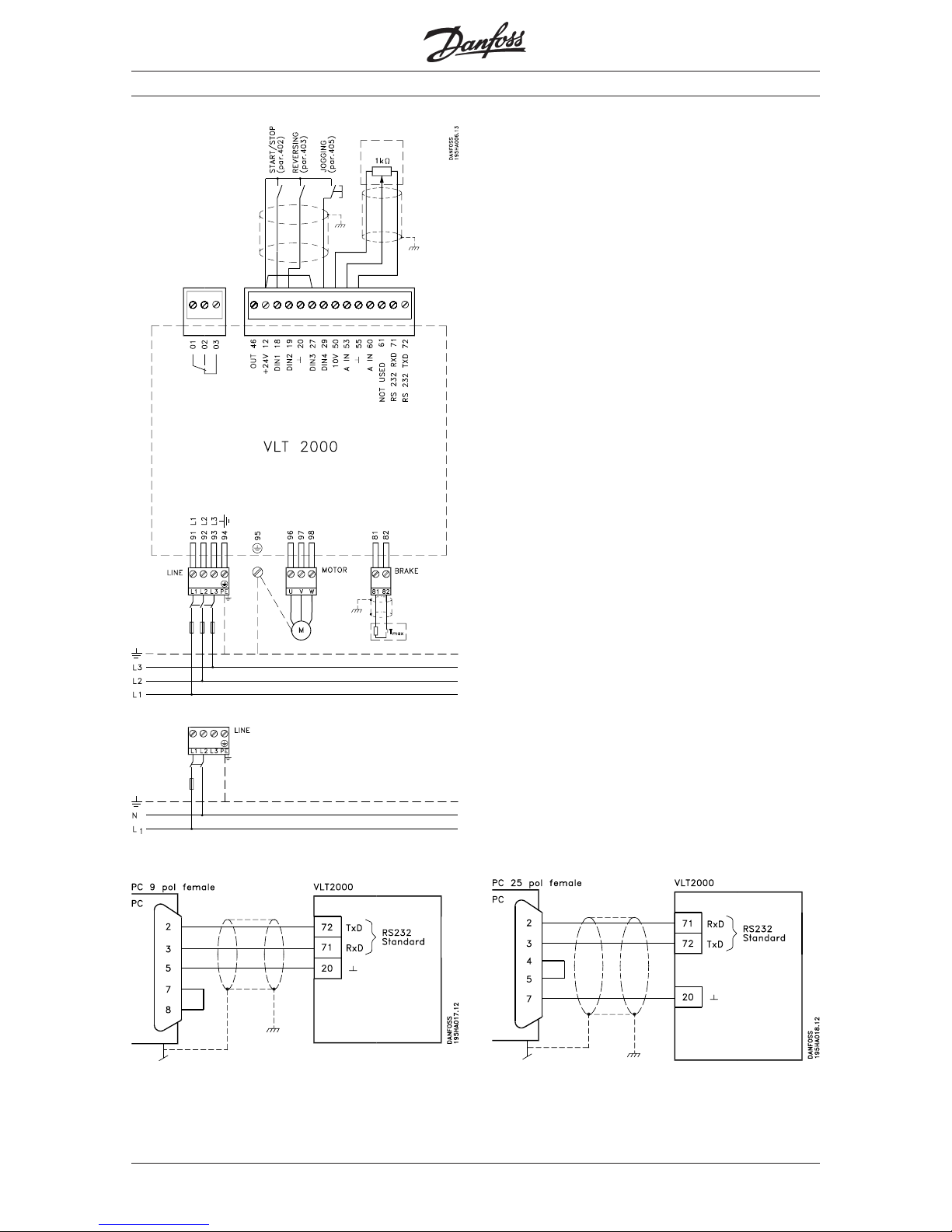
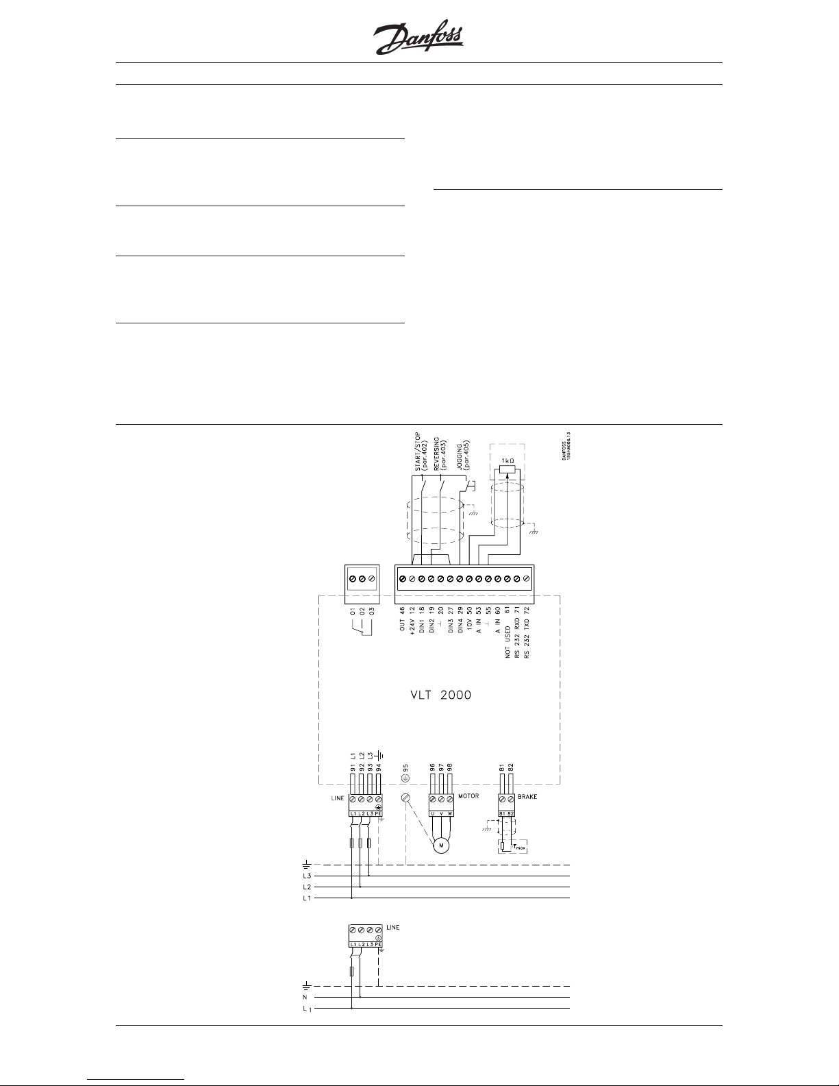
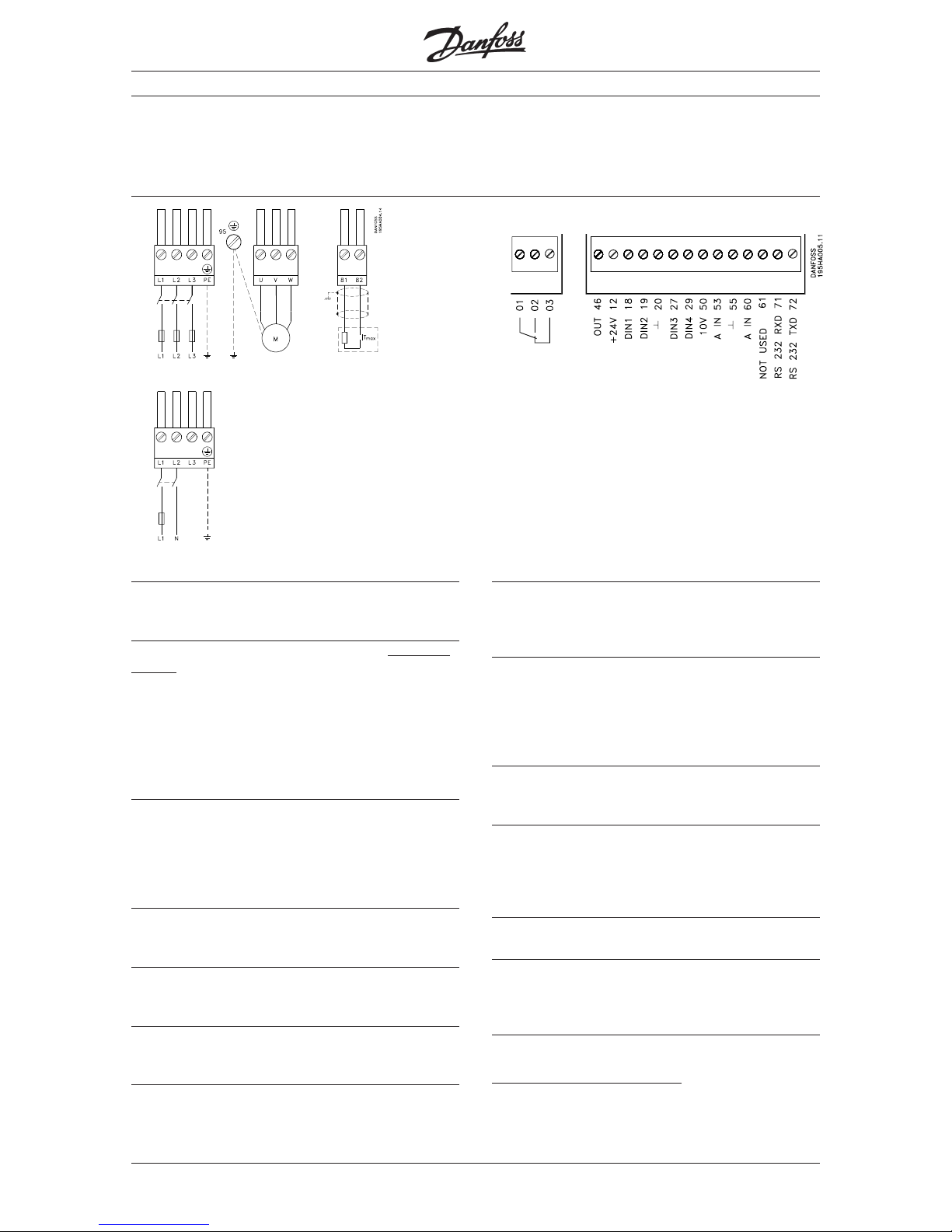
Three-phase mains connection
Single-phase mains connection
Between PC and VLT frequency converter
Page 11
MG.20.B6.02 – VLT is a registered Danfoss trademark
11
VLT® 2000 Series
Section 1 Section 2 Section 3
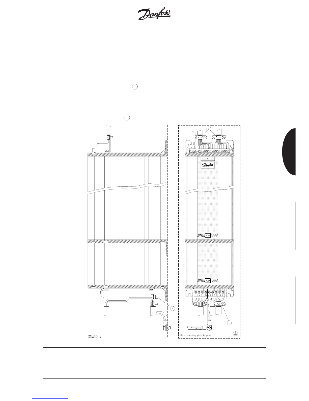
VLT 2010-2030, 1/3 x 208-240 V and VLT 20202060* 3 x 380-460 V with RFI and motor filter
module or LC and RFI filter module:
If VLT frequency converters are mounted on an
electrically conductive, metal rear plate, good
electrical connection between the VLT and the rear
plate is to be ensured (use earth screw (item A in
the drawing)).
If the VLT frequency converter is mounted on a nonconductive rear plate, it is to be ensured that there is
good grounding to the earth screw (item A in the
drawing).
For further information
When you have finished installing the VLT frequency
converter, see the section
After installation for infor-
mation about how to operate the VLT frequency
converter. You will also get information about what
parameters to choose to ensure optimum operation.
*) VLT 2060 Max. 415 V
Installation
■
Page 12

MG.20.B6.02 – VLT is a registered Danfoss trademark
VLT® 2000 Series
12
Following this installation guide the VLT® 2000 units
with built-in compact RFI filter comply with the EMC
requirements according to EN 55011 group 1A.
Technical data
The technical data on this page only apply to VLT
®
2010, 0.37 kW, VLT® 2015, 0.55 kW and VLT
®
2020,0.75 kW.with built in compact RFI filter.
■■
■■
■
Cable type: Screened
Max. length: 20 m
Mains supply: 1 x 220-240 V
Installation guide
Clamp to secure cables and cable screen type
195H6129 is delivered with the above units.
Mains supply connection:Mains supply connection:
Mains supply connection:Mains supply connection:
Mains supply connection:
Cable is secured in cable relief fitting.
Earth wire is secured in the earth screw on the
frequency converter.
Motor cable connection:Motor cable connection:
Motor cable connection:Motor cable connection:
Motor cable connection:
Motor cable and screen is secured in cable relief fitting
and the wires are connected in the motor plug.
■■
■■
■
Installation
Page 13

MG.20.B6.02 – VLT is a registered Danfoss trademark
13
VLT® 2000 Series
Section 1 Section 2 Section 3
After installation
Chapter 1 ■ Quick Setup,
If you are familiar with a VLT ...................... Page 14
■ Quick Setup,
If you are not familiar with a VLT ................ Page 14
■ A simple connection example .................... Page 14
■ How to program ........................................ Page 15
■ Survey of terminals .................................... Page 16
■ Description of connection terminals............ Page 16
■ How to check connection of
control cables ............................................. Page 17
■ Prefuses .................................................... Page 17
■ Cables ....................................................... Page 17
■ Check grounding ....................................... Page 17
■ Commissioning and testing ....................... Page 18
■ Basic settings ............................................ Page 18
Page 14
MG.20.B6.02 – VLT is a registered Danfoss trademark
VLT® 2000 Series
14
Quick Setup
If you are familiar with a VLT
If you know the VLT and how to move round in the
menus and parameters, you can go directly to steps
1-9 overleaf to get started.
Quick Set
If you are not familiar with a VLT
If you have never operated a VLT frequency converter
before, you can learn it on the basis of the
instructions on page 15.
Connection example
■
A simple connection example
In the figure below you can see a simple connection
example based on the Quick Setup programming
overleaf.
After installation
■
■
Page 15
MG.20.B6.02 – VLT is a registered Danfoss trademark
15
VLT® 2000 Series
Section 1 Section 2 Section 3
How to program
The Quick Setup shown is based on the assumption
that you want your VLT to operate with the following
setup:
1. External start/stop
2. Potentiometer connected for external speed control
3. Option to change rotation direction
4. Option to select a fixed speed (Jog)
If you use a brake module, you must program
one parameter more, and two more if you
want local operation via the display keys.
This will appear from the two tables at the bottom.
To store the data press the “menu” key!
When you have connected your VLT, as described on
the previous page, you must program a few parameeters.
Perform steps 1-9 for Quick Setup.
After installation
Standard motor with constant torque load without brake module on the frequency converter
Step Parameter Designation Settings Display indication
1 000 Language Choose English ENGLISH
2 103 Motor power Read motor plate
3 104 Motor voltage Read motor plate
4 105 Motor frequency Read motor plate
5 201 Min. frequency Set wanted frequency
6 202 Max. frequency Set wanted frequency
7 215 Ramp up 1 Set wanted ramping time
8 216 Ramp down 1 Set wanted ramping time
9 Start This is done by supplying terminals 18 and 27
the frequency with 24 V DC from the frequency converter’s terminal 12
converter or by using an external 24 V DC voltage
If a brake module is mounted, make the following settings
Step Parameter Designation Settings Display indication
1 300 Brake function If a brake module is used, choose Applied APPLIED
2 Start This is done by supplying terminals 18 and 27
the frequency with 24 V DC from the frequency converter’s terminal 12,
converter or by using an external 24 V DC voltage
If you want local operation and start, make the following settings
Step Parameter Designation Settings Display indication
1 003 Operation site Choose Local LOCAL
2 004 Local reference Record wanted output frequency by means
of the “+” and “−” keys
■
Page 16
MG.20.B6.02 – VLT is a registered Danfoss trademark
VLT® 2000 Series
16
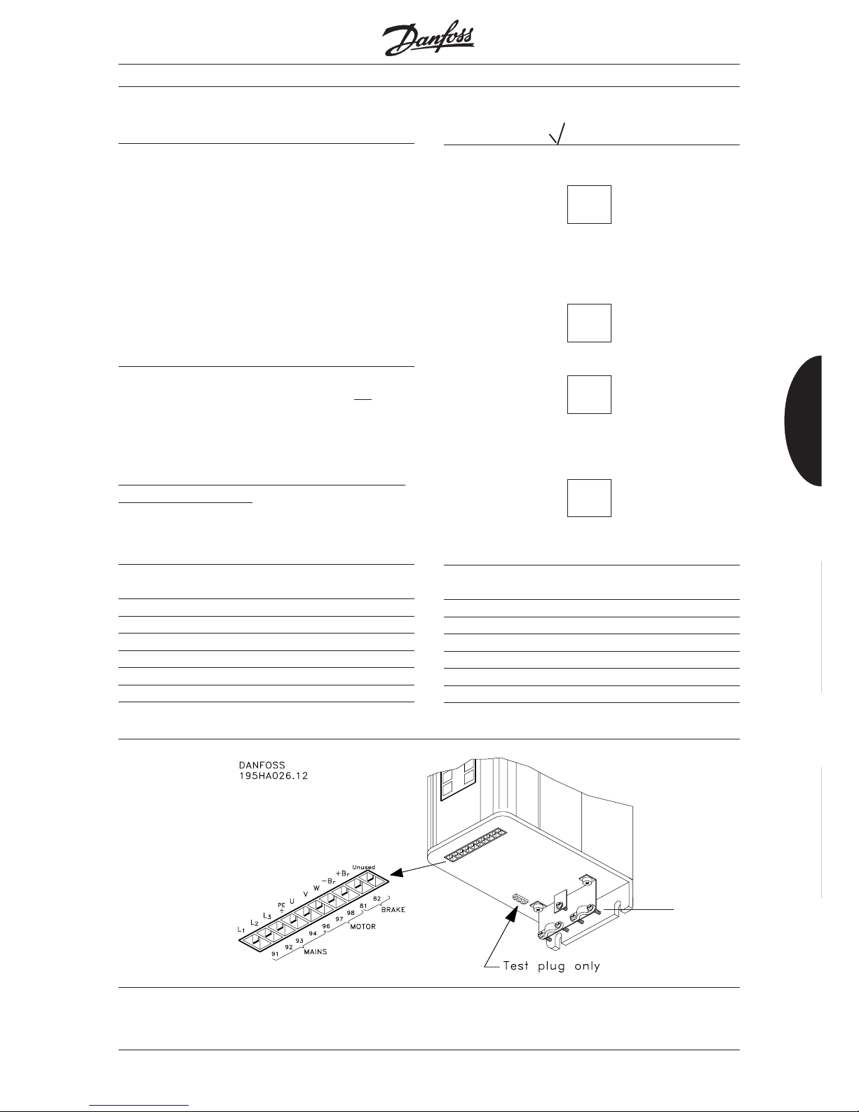
Survey of terminals
Below you will see a survey of all the terminals of a
VLT frequency converter (3 x 380-460 V).
After installation
Description of connection terminals
Terminal 12: Internal voltage supply
24 V DC activates digital inputs such as Start/stop,
Jog or Quick stop.
Terminal 18: Start/stop (Digital input)
When 24 V DC is applied the motor starts
on condit-
ion that
− digital input 27 (Quick stop) is connected
to 24 V DC.
− you have made no local stop command
(“Stop/reset” key).
− f
Max
is > 0 Hz.
− a reference signal has been given (see para. 402).
Terminal 19: Reversing (Digital input)
When 24 V DC is applied to terminal 19, the motor
starts reversing, either at once or after a stop command. If you have chosen pulse start in para. 402
(terminal 18), the start reversing function of para.
403 is automatically a pulse-activated function.
Terminal 20: Digital common
This terminal is the reference for all digital signals,
including bus.
Terminal 27: Stop (Digital input)
When you apply 0 V you can give different stop signals. See also para. 404.
Terminal 29: Jogging (Digital input)
This terminal allows you to activate a fixed
preprogrammed speed. See para. 405.
Terminal 46: Output
Using parameter 408 you can choose between
different output signals. The output is an open collector
output, and a pull-up resistor of min. 600 ohm must
therefore be connected to terminal 12 (+24 V).
Terminal 50: Internal voltage supply
With 10 V DC voltage you can set an analogue
control signal using a 1 kohm potentiometer with terminal 55 as reference.
Terminal 53: Analogue control voltage
Using parameter 412 you can choose between 0 +10 V DC or +10 - 0 V DC analogue voltage. The terminal is used together with terminals 50 and 55. The
voltage value determines the output frequency and
thus also the speed of the motor.
Terminal 55: Analogue common
Is used together with terminals 50 and 53 or together
with terminal 60.
Terminal 60: Analogue control current
Using parameter 413 you can choose between four
different input signals:
0-20 mA, 4-20 mA, 20-0 mA or 20-4 mA.
The current value determines the output frequency.
Terminal 61: Not used
Terminals 71-72: RS 232 port
Connect the terminals to a PC, if you want to control
the VLT frequency converter via PC software. Terminal
20 acts as digital common.
Terminals 81-82: Brake resistor
By means of these terminals you can connect the
brake resistor on units with brake function.
Note the live voltage 550 V DC.
The control signals and the terminals for the brake
module are described at the bottom of this page.
Mains Motor
Br.
■
■
Page 17
MG.20.B6.02 – VLT is a registered Danfoss trademark
17
VLT® 2000 Series
Section 1 Section 2 Section 3
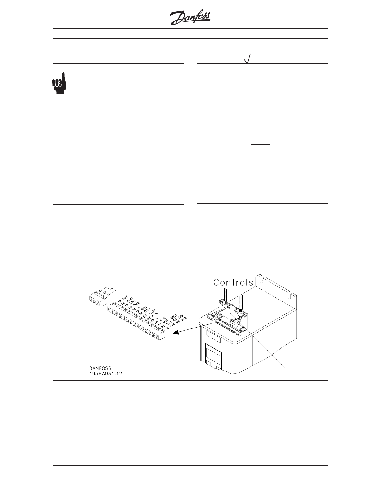
How to check connection of control cables
The VLT frequency converter must be connected so
that it is possible to control it via the different signal
inputs at the top of the enclosure.
Terminals 01-03: Relay output Max. 250 V, max. 2 A. Relay: Not activated
Terminal 12: Supply to digital inputs 24 V DC, max. 140 mA
Terminals 18-19: Digital inputs 0-24 V, Ri=2 kohm (max. 37 V for 10 sec.)
27-29 (min. on-time 80 ms.)
Terminal 46: Digital output signal (open collector) Max. 24 V DC, max. 40 mA, min. 600 ohm
Terminal 50: Supply to 1 kohm potentiometer 10 V DC, max. 12 mA
Terminal 53 Analogue control voltage +0 - 10 V DC, Ri=10 kohm, +10 - 0 V
Terminal 60: Analogue control current 0/4-20 mA, Ri=226 ohm, 20-0/4 mA
Terminals 71/72: RS 232 standard bus 71 RXD, 72 TXD, 20 dig. ref.
Terminals 81/82: Used in connection with brake resistor
Terminal 20: Digital common Must be used as reference for all digital
signals
Terminal 55: Analogue common Must be used as reference for all analogue
signals.
Prefuses
Prefuses must be installed in the mains supply to the
frequency converter.
Cables
The cables to control signals and brake resistor must
be screened. It is recommended to use unscreened
motor cable.
Motor/mains cables (max. cable cross-section)
Mains supply 1/ 3 x 208/220/230/240 V Mains supply 3 x 380-460 V
2010 2015 2020 2030 2040 2050 2020 2025 2030 2040 2050 2060*
4 mm2 for all VLT 2000 Series types 4 mm2 for all VLT 2000 Series types
Control cables (max. cable cross-section)
Mains supply 1/ 3 x 208//220/230/240 V Mains supply 3 x 380-460 V
2010 2015 2020 2030 2040 2050 2020 2025 2030 2040 2050 2060*
1.5 mm2 for all VLT 2000 Series types 1.5 mm2 for all VLT 2000 Series types
How to check the grounding
The grounded line must be connected to terminal 94
(PE). If you use a thick cable this must be connected
to the 6 mm large screw (terminal 95) in the bottom of
the VLT frequency converter.
If you use screened cables, the screen must be connected to the screen termination bracket of the VLT
frequency converter and brake resistor.
(Max. sizes)(Max. sizes)
(Max. sizes)(Max. sizes)
(Max. sizes)
Mains supply 1/3 x 208/220/230/240 V Mains supply 3 x 380-460 V
2010 2015 2020 2030 2040 2050 2020 2025 2030 2040 2050 2060*
10 A 16 A 20 A 20 A 20 A 25 A 16 A 16 A 16 A 16 A 16 A 20 A
After installation
*) VLT 2060: Max. 415V
■
■
■
■
Page 18
MG.20.B6.02 – VLT is a registered Danfoss trademark
VLT® 2000 Series
18
c) Make a quick stop by means of disconnecting
between terminal 27 and terminal 12.
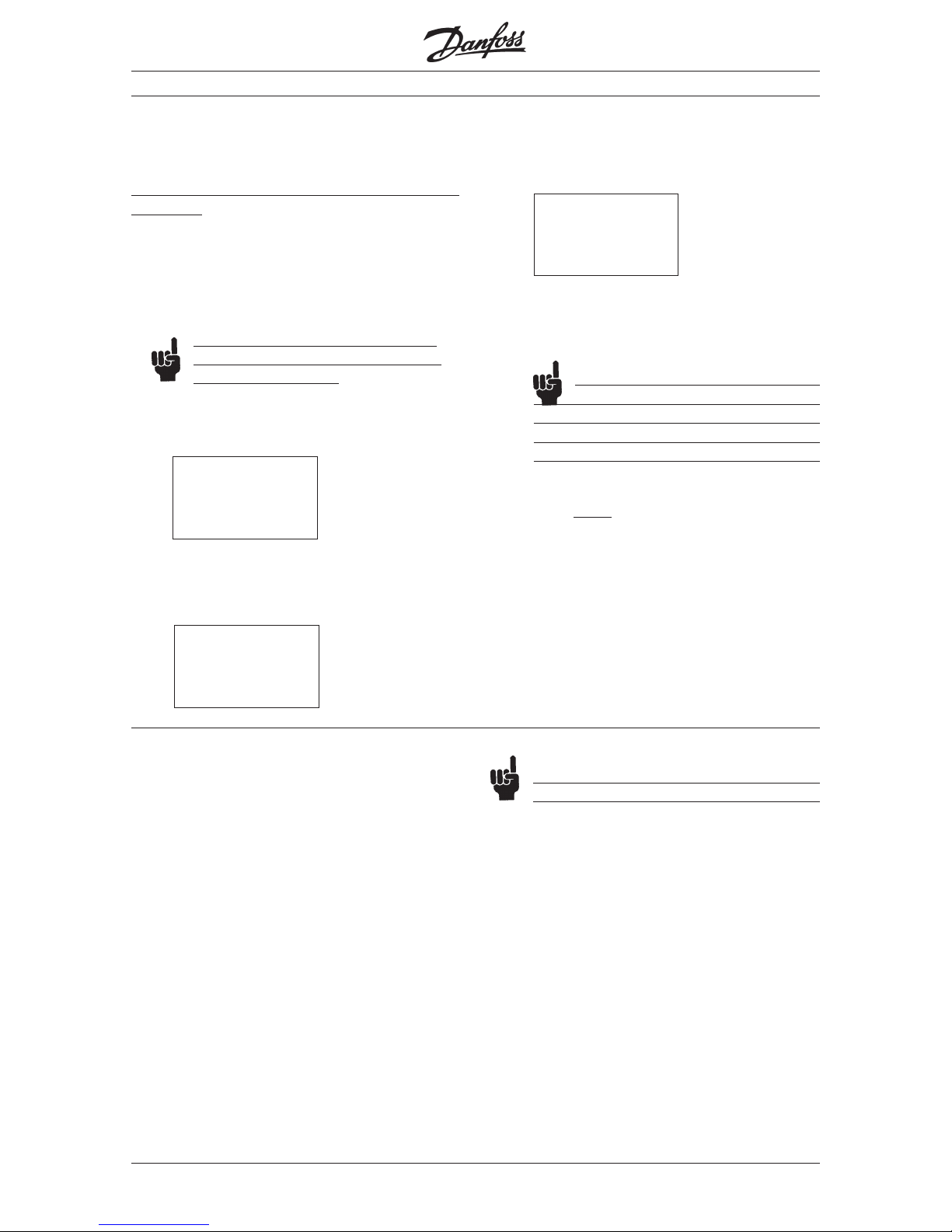
Example of display indication:
During the simulation you can see that the VLT
frequency converter reacts by watching the
display indications.
If no external control has been
connected, you can choose to simulate
the function of the VLT frequency converter
locally via the keyboard. See description at
the bottom of page 31.
5. Press the “Stop” key to stop the VLT frequency
converter
before you connect the motor.
6. Test the whole system (repeat steps 4 and 5) with
the motor connected to check the direction of
rotation.
Commissioning and testing
When the VLT frequency converter has been connected to
control signals, you may want to test the system.
This following test is not suitable if you use the built-in
PI controller.
1. Disconnect the motor from the VLT frequency
converter.
2. Connect the VLT frequency converter to the mains.
3. Make the necessary settings such as min./max.
frequency and connect the necessary control
signals, possibly via PLC.
As a minimum you must set the parameters
and connect the control signals as described
in chapter 1, Quick Setup.
4. Make a simulation without motor:
a) Give a start signal via a contact to terminal 18.
Example of display indication:
b) The speed (frequency) can be changed by
means of the potentiometer connected.
Example of display indication:
After installation
00,0 Hz
FREQUENCY
STOP 1
23,7 Hz
FREQUENCY ➜
FUNCTION OK 1
30,0 Hz
FREQUENCY ➜
FUNCTION OK 1
Basic settings
The VLT frequency converter has been preset from
the factory so that normally it will function after a few
data values are recorded/changed.
See Quick Setup on page 15.
The factory settings of the VLT frequency
converter are listed on page
105.
.
.
.
■
■
Page 19

MG.20.B6.02 – VLT is a registered Danfoss trademark
19
VLT® 2000 Series
Section 1 Section 2 Section 3
Chapter 1 ■ How the VLT works ................................... Page 21
Technology
Chapter 2 ■ How to size your VLT ................................. Page 29
Product range, sizing, technical data
Chapter 3 ■ How to install your VLT .............................. Page 41
The connection terminals, dimensions,
mechanical installation, electrical installation,
and motor connection
Chapter 4 ■ How to operate your VLT ........................... Page 45
The control panel and
the structure of the menus
Chapter 5 ■ The control possibilities of the VLT ............. Page 51
The menu groups and
the various parameters
Chapter 6Chapter 6
Chapter 6Chapter 6
Chapter 6 ■ Description of parameters ......................... Page 59
Chapter 7 ■ Display messages ..................................... Page 81
Status, alarm and warning and
reset messages
Chapter 8 ■ Special conditions ..................................... Page 85
CE-labelling
EMC, extreme operational conditions,
electrical noise, air humidity, efficiency and
du/dt measurements
Chapter 9 ■ Factory settings and service ...................... Page 97
Factory settings and fault location
Form to note down the VLT
parameter settings
Chapter 10 ■ Subject index .......................................... Page 107
Contents
Page 20

Page 21

MG.20.B6.02 – VLT is a registered Danfoss trademark
21
VLT® 2000 Series
Section 1 Section 2 Section 3
Chapter 1 ■ How the VLT is built up .............................. Page 22
■ The Danfoss VVC principle ........................ Page 23
■ Factory-programmed optimization............. Page 24
■ Control accuracy ....................................... Page 25
■ Protection against mains disturbance........ Page 25
■ Galvanic isolation....................................... Page 25
■ Advanced motor protection ....................... Page 25
■ Long motor cables .................................... Page 25
■ Functional diagrams .................................. Page 26
How the VLT works
Page 22
MG.20.B6.02 – VLT is a registered Danfoss trademark
VLT® 2000 Series
22
Saved energy
Energy is saved when the motor runs at a speed
which is continually matched to the momentary
requirement. An example is a pump and ventilating
plant, where a frequency converter can reduce energy
consumption by the cube of the speed.
Improved process
Matching the speed to the production process has
several advantages: an increase in production and a
decrease in the consumption of materials and the
scrapping rate.
Improved quality
The number of starts and stops is reduced. This avoids
unnecessarily hard treatment of machine parts.
Less maintenance
The frequency converter requires no maintenance.
In water supply plants there are no pressure surges
which might damage the water pipes.
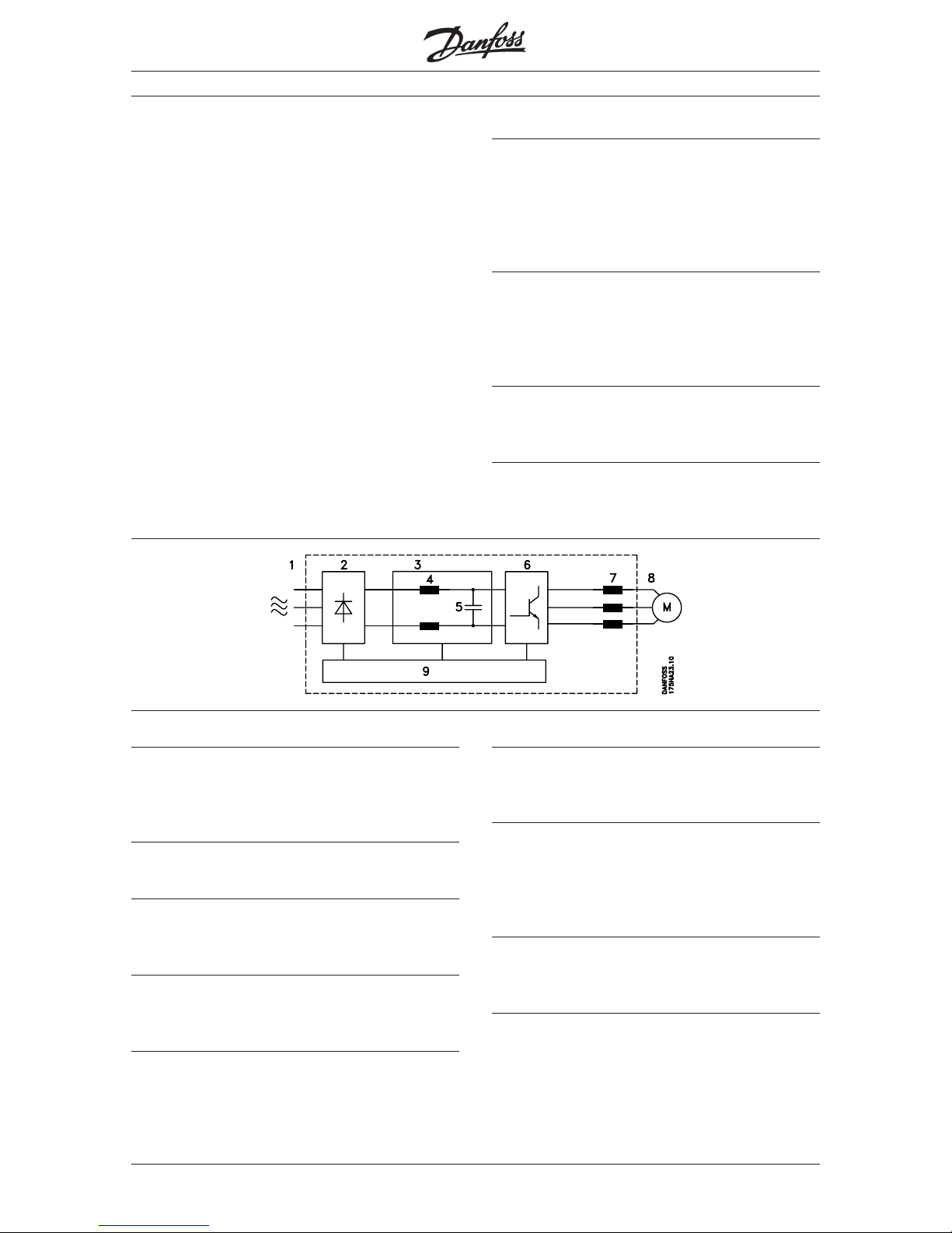
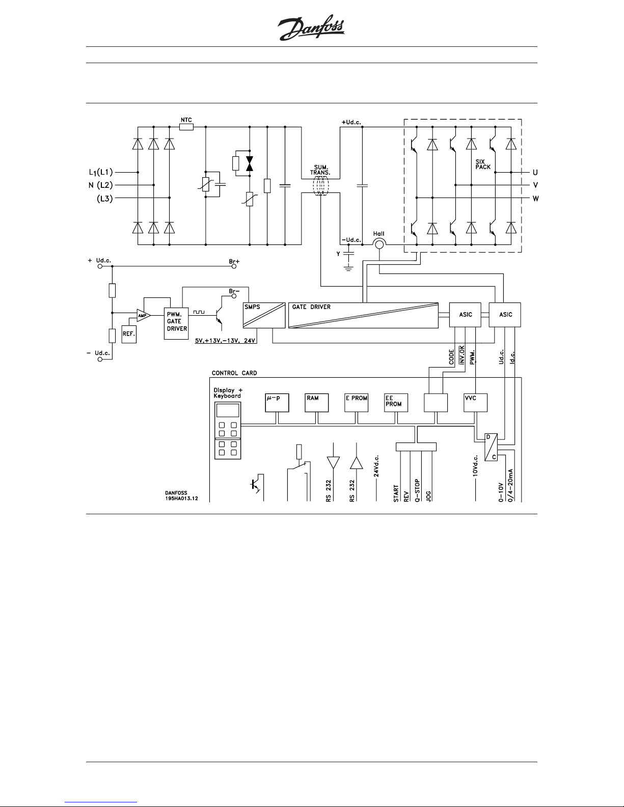
1. Mains supply
1 × 220/230/240 V AC, 50/60 Hz
3 × 208/220/230/240 V AC, 50/60 Hz
3 × 380/400/415/440/460 V AC, 50/60 Hz
2. Rectifier
Three-phase rectifier bridge rectifies AC to DC.
3. Intermediate circuit
DC voltage = √2 × supply voltage
4. Coils in the intermediate circuit
(not all VLT 2000 units)
Smoothen DC voltage and limit mains
supply interference (mains harmonics).
5. Capacitors in the intermediate circuit
Smoothen the voltage of the intermediate circuit
(energy store).
6. Inverter
Converts DC voltage to variable a.c.voltage and
variable frequency.
7. Motor coils (as module)
Advantages of motor coils:
− You can use long motor cables.
− Unlimited switching at the output of
the frequency converter (trip may occur).
8. Output
Variable a.c. voltage,10-100% of the supply voltage.
Variable frequency: 0-120/0-500 Hz.
9. Control card
The integrated computer controls the inverter, which
generates the pulse pattern by means of which DC
voltage is converted to variable a.c. voltage and
variable frequency.
How the VLT works
How the VLT is built up
A frequency converter is an electronic unit for infinite
speed control of a.c. motors. The frequency converter
controls the motor speed by converting the fixed voltage and frequency of the supply mains, e.g. 400 V/
50 Hz, to variable values. The frequency converter
does this by rectifying a.c. voltage to DCvoltage and
converting this to a.c. voltage with variable amplitude
and frequency.
The variable voltage and frequency supplying the motor
make infinite speed control of standard three-phase,
asynchronous motors possible.Today the a.c. motor
controlled by a frequency converter is a natural part of
all automised plants. Apart from utitilizing the good features of the a.c. motor, the infinite speed control gives
the user a multitude of additional advantages:
■■
■■
■
Page 23
MG.20.B6.02 – VLT is a registered Danfoss trademark
23
VLT® 2000 Series
Section 1 Section 2 Section 3
The Danfoss VVC principle
VLT 2000 Series frequency converters use an inverter
control system known as the Voltage Vector Control
(VVC) developed by Danfoss.
The VVC principle is superior to the traditional PWM
(Pulse Width Modulation) principle used in most
modern frequency converters in the following ways:
− Full-rated motor voltage at rated motor frequency.
− Near perfect resemblance to the sinusoidal
mains supply.
− Extremely low switching losses, resulting in high
converter efficiency.
The features are obtained through a special switching
pattern: the switching intervals are very short, which
means high switching frequency, and the six
semiconductors of the inverter section are alternately
held inactive in pairs, throughout a 60° sine period.
The current wave form of the motor current closely
resembles that obtained on mains operation. The
switching pause in 60° of the sine period also means
that full-rated motor voltage can be obtained - and
inverter switching losses are reduced by about
one third.
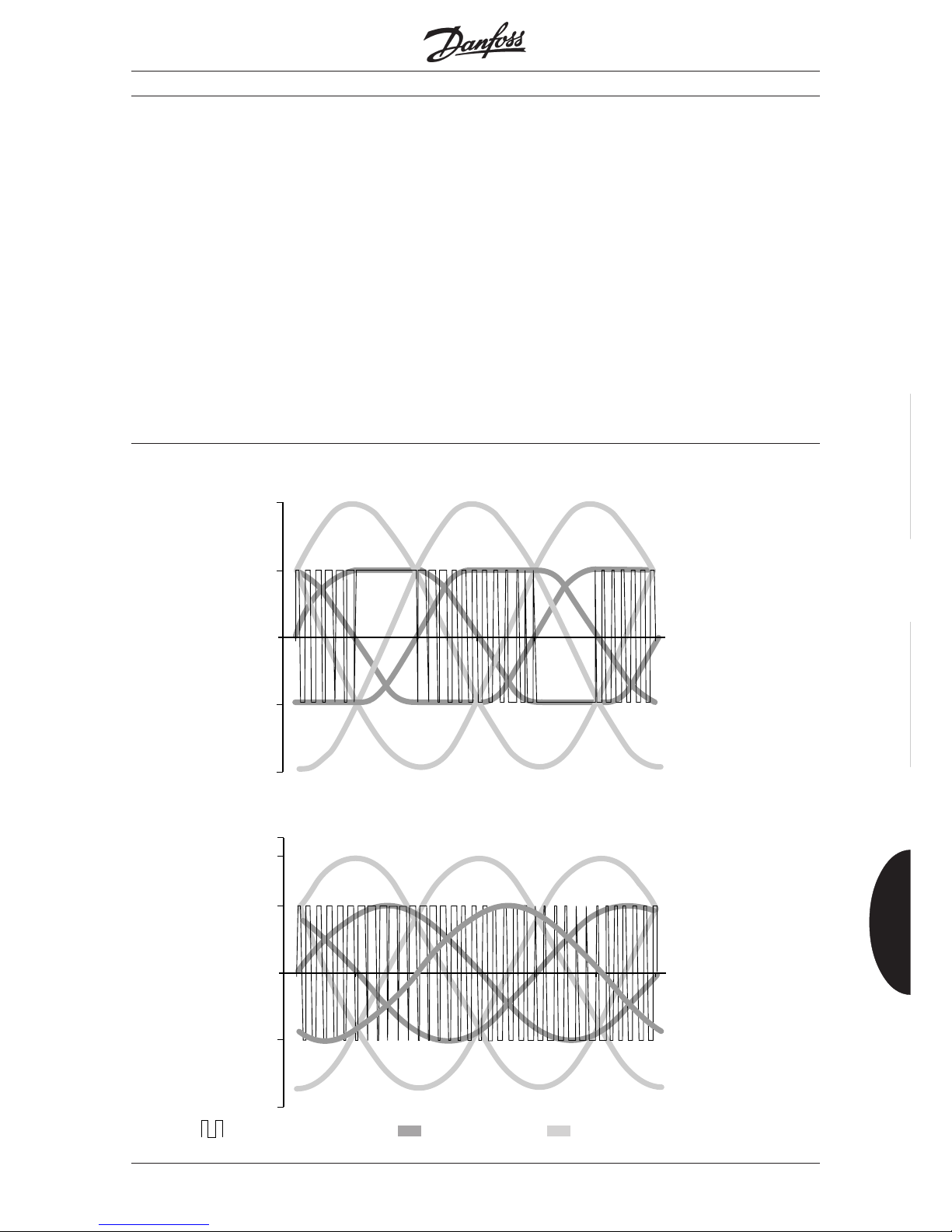
The figures below show the switching pattern and
maximum motor voltage according to the VVC
principle and the traditional PWM principle
respectively.
The full-rated motor voltage and the perfect current
wave form mean that the Danfoss VLT 2000 Series
allows full motor performance without any derating just like running the motor on the mains.
Motor voltage and simplified switching pattern according to the Danfoss VVC principle
Motor voltage and simplified switching pattern according to the traditional PWM principle
0,50
0,00
1,00
-0,50
-1.00
0 60 120 180 300 360240
U-V U-W W-U
U-V V-W W-U
0,50
0,00
1,00
-0,50
-1.00
0 60 120 180 300 360240
0,866
U-V V-W W-U
Switching pattern for phase U
Single phase voltage
Phase-phase voltage
for motor
How the VLT works
■
Page 24
MG.20.B6.02 – VLT is a registered Danfoss trademark
VLT® 2000 Series
24
How the VLT works
Factory-programmed optimization
VLT Series 2000 has dynamic adaptation of the
motor voltage and frequency. This ensures
correct magnetisation of the motor, thus
providing optimum dynamics, accuracy or efficiency.
VLT has been designed for operation of the most
common types of motors and loads.
Once parameters 103,104, 105, 107 and 108 have
been set according to the motor type plate, your
motor operation will be optimum in most cases.
Individual adaptation of VLT and motor is done via
parameters 109-112.
Start voltage
increases the motor voltage at a given frequency. This
increases the motor magnetization. The motor can yield
a higher torque, but the disadvantage is that the motor
losses are increased too. The result is a higher motor
temperature. Excessive start voltage can cause a trip
(cut-out).
Start compensation
changes the motor voltage as a function of the load.
The voltage will increase with higher motor current.
Over-compensation will overheat the motor and give
the risk of instability and can cause trip (cut-out). As
the name indicates, the function is most effective at
low motor speed.
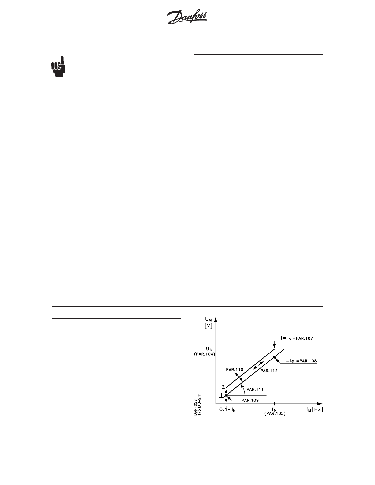
U/f ratio
This describes the pre-programmed U/f characteristics
which indicate the relation between motor voltage (U)
and frequency (f).
The U/f ratio can be adjusted to ensure correct
excitation of the motor, thereby helping to
obtain optimal dynamism, accuracy or efficiency.
Slip compensation
adds both frequency and voltage and compensates for
the varying slip at varying load so that the motor speed
is kept constant at varying load. Over-compensation
may make the speed increase at increasing load. This
means motor overload and risk of unstable motor
operation.
Constant torque CT
Par. 104 = Rated motor voltage
Par. 105 = Rated motor frequency
Par. 107 = Rated motor current
Par. 108 = Motor no-load current
Par. 109 = Start voltage
Par. 110 = Start compensation
Par. 111 = U/f ratio
Par. 112 = Slip compensation
■
Page 25
MG.20.B6.02 – VLT is a registered Danfoss trademark
25
VLT® 2000 Series
Section 1 Section 2 Section 3
How the VLT works
Control accuracy
Basically we distinguish between open loop and
closed loop control.When the control is an open loop
type the motor current acts as process feedback. The
final result is therefore highly dependent on the
characteristics of the motor.
Note that large motors give a better result than small
motors.
Open loop (depending on motor size) ±2.0 % 3-100 Hz (10-90% of max. torque)
PI (closed loop) ±0.5% 1.2-100 Hz (-90 - +90% of max. torque)
A closed loop control incorporates a direct process
feedback, which substantially improves the control
accuracy.
The stated maximum torque follows the power hyperbola in the frequency range across the motor’s rated
frequency.
Galvanic isolation
With the VLT 2000 Series safety isolation is standard,
as the high-voltage parts of the power section are
galvanically isolated from the low-voltage parts of the
control section according to VDE 0160/0106 (PELV).
Therefore PCs and the like will not be disturbed.
Advanced motor protection
The VLT 2000 Series has a built-in electronic thermal
motor protection. The frequency converter calculates
the motor temperature on the basis of voltage,
current, frequency and time.
The thermal motor protection is comparable with a
thermal relay in the motor cables. Therefore it is
superior to the traditional bi-metallic protection, where
the altered cooling conditions due to the speed
control are not taken into consideration.
Long motor cables
For the VLT 2000 Series motor coils in an IP 00 or IP
10 enclosure are available as modules.
This makes it possible to install a long cable between
motor and frequency converter.
Motor coils are also included in the RFI and motor
filter module in IP 20 enclosure. See page 34 for a
speciffication of maximum cable length.
Programmable control inputs and
signal outputs in 2 setups
The digital technique used in the VLT 2000 Series
makes it possible to redefine the different control
inputs and signal outputs and to program 2 different
user defined setups.
It is easy for the user to program the required
functions on the keyboard of the VLT 2000 Series or
via the RS 232 user interface.
Protection against mains disturbance
The VLT 2000 Series is protected against transients
arising on the mains, e.g. when you switch in power
factor phase-correction capacitors or when the
supply is subject to lightning strikes.
Adequate motor voltage and full torque can be maintained down to 10% under-voltage on the supply
mains.
■
■
■
■
■
■
Page 26
MG.20.B6.02 – VLT is a registered Danfoss trademark
VLT® 2000 Series
26
How the VLT works
Functional diagram VLT 2010-2030 single-phase/three-phase 208-240 V
■
Page 27
MG.20.B6.02 – VLT is a registered Danfoss trademark
27
VLT® 2000 Series
Section 1 Section 2 Section 3
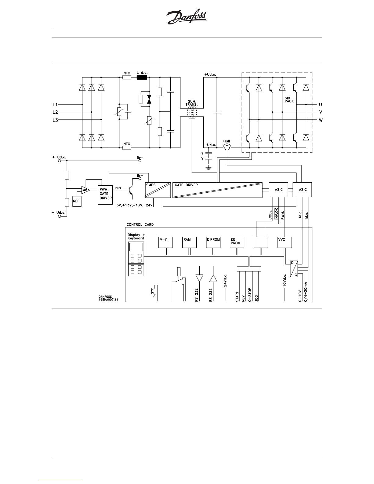
Function diagram VLT 2040-2050, 3-phase 208-240 V
How the VLT works
■
Page 28
MG.20.B6.02 – VLT is a registered Danfoss trademark
VLT® 2000 Series
28
How the VLT works
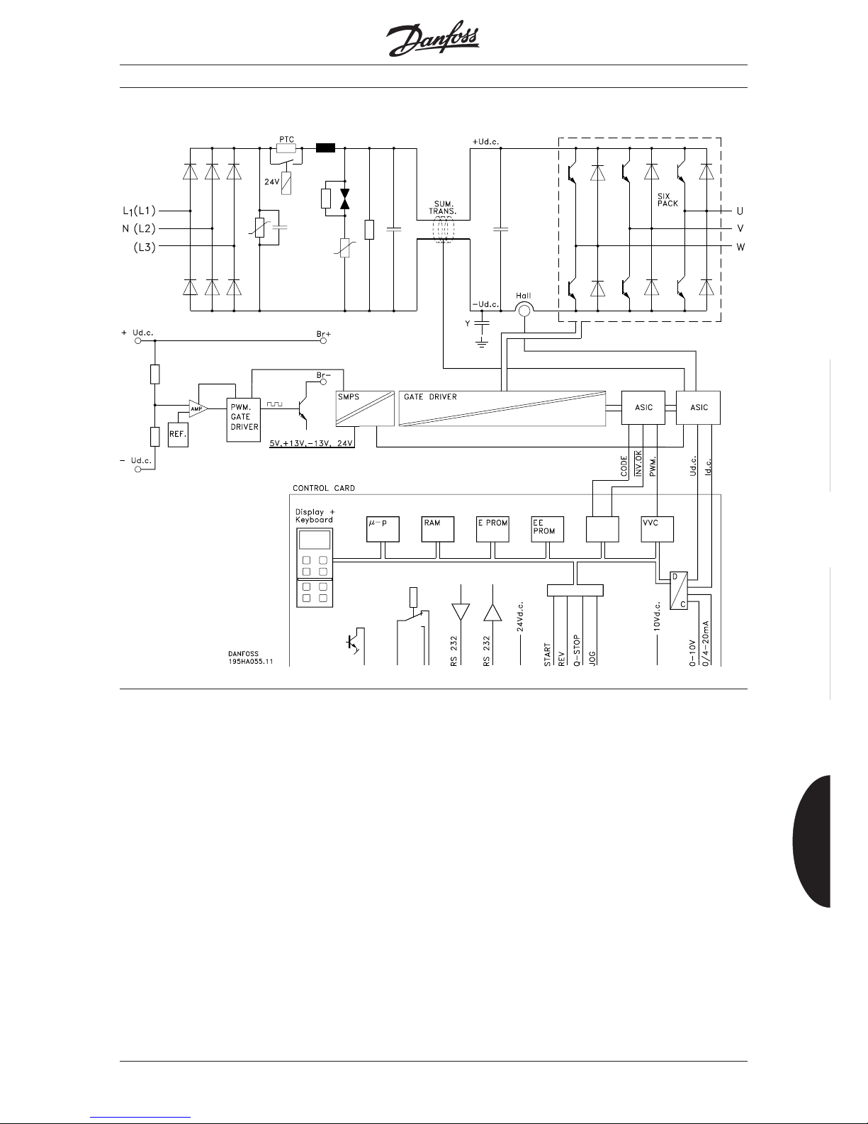
Functional diagram VLT 2020-2060 three-phase 380-460 V
■
Page 29

MG.20.B6.02 – VLT is a registered Danfoss trademark
29
VLT® 2000 Series
Section 1 Section 2 Section 3
Chapter 2 ■ Selection of frequency converter ............... Page 30
Sizing ....................................................... Page 30
■ Product range ........................................... Page 31
■ Brake function ........................................... Page 33
■ Motor coils (module) .................................. Page 34
■ RFI and motor filter (module) ..................... Page
34
■ LC and RFI filter (module) .......................... Page 34
■ Dimensions ............................................... Page 35
■ Technical data ........................................... Page 38
How to size your VLT
■
■
■
Page 30
MG.20.B6.02 – VLT is a registered Danfoss trademark
VLT® 2000 Series
30
How to size your VLT
Selection of frequency converter
Usually the size of frequency converter is chosen on
the basis of the shaft output, as this may be the only
value known. However, if the data are known for both
the application, the motor and the frequency converter,
it is recommended to make a more accurate sizing.
The values must be based on the rated motor speed.
VLT 2000 only operates according to the CT
(constant torque) characteristic
Sizing when you know the motor current
Exercise
Conveyor plant with a 1.1 kW, 3 × 380 V motor. At
continuous operation the motor current is 2.5 A
( 3 × 415 V).
Solution
From the table on the next page you can see that a
VLT type 2025 can yield 2.8 A at continuous operation. The right solution is therefore VLT 2025.
Sizing on the basis of the apparent power S
M
[kVA] consumed by the motor
Exercise
A motor must yield constant torque at continous
operation. Usually the necessary values will appear
from the motor plate or from the motor catalogue.
Solution
From the table on the next page you can see that VLT
type 2025 can yield 2.0 kVA (415 V) at continuous
operation. The solution is therefore VLT type 2025.
Read values
Motor current = 2.5 A (3 × 415 V)
s
M
=
U × I × √3
[kVA]
1000
=
415 × 2.5 × √3
[kVA]
1000
= 1.8 kVA
Sizing on the basis of the power requirement
P
VLT
[kW] of the motor
Exercise
A machine tool is driven by a 3 kW motor. The power
requirement is indicated to be 2.4 kW. The motor
efficiency η is 0.80, cos ϕ = 0.81 and the motor voltage is 3 x 415 V.
η and cos ϕ are measured at 3 kW output. We
estimate η and cos ϕ to be approximately the same
at 80 % load.
Solution
From the table on the next page you can see that VLT
type 2040 can yield 4.0 kVA (415 V) at continuous
operation. The right solution is therefore VLT type 2040.
S
VLT
=
P
m
η × cos ϕ
=
2.4 kW
0.80 × 0.81
= 3.7 kVA
■
■
■
■
Page 31

MG.20.B6.02 – VLT is a registered Danfoss trademark
31
VLT® 2000 Series
Section 1 Section 2 Section 3
Which one to choose?
Mains: 1 × 220/230/240 V, 3 × 208/220/230/240 V
VLT type Typical shaft output Constant output current I
VLT,N
Constant output power at 230 V
[kW] [A] [kVA]
2010 0.37 2.2 0.9
2015 0.55 3.1 1.3
2020 0.75 4.0 1.6
2030 1.5 7.5 3.1
2040 *) 2.2 10.6 4.4
2050 *) 3.0 16.7 6.9
*) VLT types 2040 and 2050: only three-phase mains supply.
Mains: 3 × 380/400/415/440/460 V *)
VLT type Typical shaft output Constant output current I
VLT,N
Constant output power at 415 V
[kW] [A] [kVA]
2020 0.75 2.4 1.7
2025 1.1 2.8 2.0
2030 1.5 4.0 2.9
2040 2.2 5.6 4.0
2050 3.0 7.6 5.5
2060 *) 4.0 9.7 7.0
*) VLT type 2060: 3 × 380/400/415 V
How to size your VLT
■
Page 32

MG.20.B6.02 – VLT is a registered Danfoss trademark
VLT® 2000 Series
32
How to size your VLT
Product range
The VLT 2000 Series is available in a single-phase/
three-phase version (1 x 220-240 V or 3 x 208-240V)
in the power range 0.37-1.5 kW and a three-phase
version (3 x 208-240 V) in the power range 2.2-3.0
kW. A three-phase version (3 x 380-460 V) in the
power range 0.75-4.0 kW is also available.
All units are delivered in an IP 20 enclosure.
How to find the right code number
When you have found the right VLT size you can find
the code number to be ordered in the table below.
Example:
VLT type 2020 (3 x 380-460 V) three-phase without
display with brake has the code number 195H3400.
As appears from the table a VLT 2000 single/three
phase can be delivered with various options and
modules such as brake function, RFI filter and motor
coils.
VLT 2000 Series, single-phase/three-phase (1
× ×
× ×
× 220-240 V / 3
× ×
× ×
× 208-240 V) (3 x 208-240 V)
VLT 2010 VLT 2015 VLT 2020 VLT 2030 VLT 2040 VLT 2050
Without display 195H3100 195H3102 195H3104 195H3106 195H3108 195H3110
With display 195H3101 195H3103 195H3105 195H3107 195H3109 195H3111
Without display with brake 195H3200 195H3202 195H3204 195H3206 195H3208 195H3210
With display with brake 195H3201 195H3203 195H3205 195H3207 195H3209 195H3211
RFI and motor filter module 195H6523 195H6524 195H6524 195H6525
IP 20 1-phase
RFI and motor filter module 195H6522 195H6522 195H6522 195H6522
IP 20 3-phase
RFI-filtermodul IP 20 (VBG-4)* - - - - 195H6528 195H6528
Motor coil module IP 00 195H6510 195H6510 195H6510 195H6510
Motor coil module IP 10 (VBG-4) 195H6521 195H6521 195H6521 195H6521
LC and RFI filter module 195H6527 195H6526 195H6526 195H6526
IP 20 3-phase
* Schaffner RFI-filter type FN351 - 16/29
VLT 2000 Series, three-phase (3
× ×
× ×
× 380/460 V). Note: VLT 2060: 380/415 V
VLT 2020 VLT 2025 VLT 2030 VLT 2040 VLT 2050 VLT 2060
Without display 195H3300 195H3302 195H3304 195H3306 195H3308 195H3310
With display 195H3301 195H3303 195H3305 195H3307 195H3309 195H3311
Without display with brake 195H3400 195H3402 195H3404 195H3406 195H3408 195H3410
With display with brake 195H3401 195H3403 195H3405 195H3407 195H3409 195H3411
RFI and motor filter module IP 20** 195H6522 195H6522 195H6522 195H6522 195H6522 195H6522
Motor coil module IP 10 (VBG-4) 195H6521 195H6521 195H6521 195H6521 195H6521 195H6521
LC and RFI filter module IP 20** 195H6527 195H6527 195H6527 195H6526 195H6526 195H6526
**Only 380/415 V
■
■
Page 33

MG.20.B6.02 – VLT is a registered Danfoss trademark
33
VLT® 2000 Series
Section 1 Section 2 Section 3
How to size your VLT
Brake function
All units can be delivered with built-in brake function
(factory-mounted). The brake resistors for the brake
function must be connected according to the connection diagram on page 42.
Specifications VLT 2010-2030 VLT 2040-2050 VLT 2020-2050 VLT 2060
208-240 V 208-240 V 380-460 V 380-415 V
Max. current 5.5 A 16 A 5.5 A 7.5 A
Min. brake voltage 372 V DC 372 V DC 747 V DC 646 V DC
Max. brake voltage 382 V DC 382 V DC 764 V DC 661 V DC
P-band 4 V 8 V 8 V 8 V
Overcurrent fuse None None None None
Min. brake resistance 70 Ohm 25 Ohm 140 Ohm 90 Ohm
The VLT
®
2000 with built-in RFI filter in IP 20 enclosure,
is designed to be built directly into control panels.
,
EMC demands are fulfiled without any extra
component.
- RFI filter to reduce electromagnetic interference.
- The VLT
®
2000 units meet all necessary EMC
immunity standards as laid down in the IEC 1000-4.
- The VLT
®
2000 units meet the EMC emission
requirements as laid down in the EN 55011,
Group 1 Class A. The EMC emission specifications
are complied with by using up to 40 m unscreened
cable, see page 88.
VLT Series 2000, single-phase (1 x 220-240 V)
VLT 2010 VLT 2015 VLT 2020 VLT 2030
Without display 195H3600 195H3602 195H3604 195H3606
With display 195H3601 195H3603 195H3605 195H3607
Without display / With brake 195H3700 195H3702 195H3704 195H3706
With display / with brake 195H3701 195H3703 195H3705 195H3707
Motor coils, IP20, three-phase 195H6529 195H6529 195H6529 195H6529
VLT Series 2000, three-phase (3 x 380-415 V)
VLT 2020 VLT2025 VLT2030 VLT 2040 VLT 2050 VLT 2060
Without display 195H3800 195H3802 195H3804 195H3806 195H3808 195H3810
With display 195H3801 195H3803 195H3805 195H3807 195H3809 195H3811
Without display / With brake 195H3900 195H3902 195H3904 195H3906 195H3908 195H3910
With display / with brake 195H3901 195H3903 195H3905 195H3907 195H3909 195H3911
Motor coils, IP20, three-phase 195H6529 195H6529 195H6529 195H6529 195H6529 195H6529
VLT 2000 Series built-in RFI filter EN 55011 1A:
■
■
VLT Series 2000, single-phase (1 x 220-240 V)
VLT 2010 VLT 2015 VLT 2020
With display / without brake 195H3112 195H3113 195H3114
VLT 2000 Series built-in compact RFI filter
For technical data, see page 12.
■
Accessories/options to the VLT Series 2000:
Remote control (option) 175H1788
PC program (VLS Dialog 2)(
DanishDanish
DanishDanish
Danish) 175H2877
PC program (VLS Dialog 2)(
EnglishEnglish
EnglishEnglish
English) 175H2850
PC program (VLS Dialog 2)(
GermanGerman
GermanGerman
German) 175H2876
■
Page 34

MG.20.B6.02 – VLT is a registered Danfoss trademark
VLT® 2000 Series
34
How to size your VLT
LC and RFI filter (module)
The LC and RFI filter module in IP 20 enclosure is
designed to be built in with the VLT frequency
converter itself. The filter contains the following:
- RFI filter to reduce electro-magnetic
interference
- LC filter to reduce the acoustic noise level from the
motor and make it possible to use long motor
cables up to 300 m.
- Motor filter (motor RFI filter) to reduce the electromagnetic interference from the motor cable.
Equipped with the IP 20 LC and RFI filter
(195H6526 and 195H6527), the VLT 2000 Series
meets the EN 55011, Group 1, Class A requirements
of EMC emission.
The EMC emission specifications are complied with
by using up to 100 m unscreened motor cable.
Code nr. 195H6527 195H6526
VLT basic unit VLT 2020, 2025, 2030 VLT 2040, 2050, 2060
Enclosure IP 20 IP 20
Outside dimensions (H x W x D) 170 x 110 x 180 mm 170 x 110 x 180 mm
Built-in fan Yes No
Mains voltage 380 - 415 V 380 - 415 V
Current (max.) 4.0 A 9.7 A
Cut-out frequency No limit No limit
EMC immunity IEC 801 Series IEC 801 Series
EMC emission EN 55011 Group 1, Class A EN 55011 Group 1, Class A
Max. cable length to fullfill
EN 55011, Group 1, Class A 100 m 100 m
Unscreened
Max. temperature (full load) 40°C 40°C
Motor coils (module)
The IP 20 enclosure (also with mains filter) is available
with integrated motor coils or as an IP 00/IP 10
module for external mounting.
Technical data
208-240 V/IP 20 208-240V/IP 00 380-415 V/IP 20 380-460 V/IP 10
Max. current 3 × 2.2/4.0/7.5 A 3 × 7.5 A 3 × 9.7 A 3 × 10 A
Max. cable length (unscreened) 150 m 300 m 150 m 300 m
Max. cable length to fullfill
EN 55011, Group 1, Class A100 m - 100 m Unscreened
Max. cable length (screened) 75 m 150 m 75 m 150 m
Inductance 3× 75 µH 75 µH 120 µH 240 µH
Outside dimensions 100x110x180 mm - 100x110x180 mm Code no. 195H6523,6524,6525 195H6510 195H6522
195H6521
Additional litterature:
MI.20.CX.02 - Moter coil, IP 10
MI.20.BX.52 - Moter coil, IP 00
MD.65.BX.XX - Brake resistors
Motor coils in IP 00 and IP 10 enclosure contain only
one motor coil, making it possible to use long motor
cables up to 300 m. These motor coils must be
installed separately (not for co-building with the VLT
frequency converter).
RFI and motor filter (module)
The RFI and motor filter module in IP 20 enclosure is
designed to be built in with the VLT frequency
converter itself. The filter contains the following:
- RFI filter to reduce electro-magnetic
interference.
- Motor coils making it possible to use long motor
cables.
- Motor filter (motor RFI filter) to reduce the electromagnetic interference from the motor cable.
The VLT 2000 Series basic units meet EMC immunity
requirements as laid down in the IEC 1000-4
standards, but do not meet any EMC emission
requirements.
Equipped with the IP 20 RFI and motor filter
(195H6522, 195H6523, 195H6524, 195H6525),
the VLT 2000 Series meets the EN 55011, Group 1,
Class A requirements of EMC emission.
The EMC emission specifications are complied with
by using up to 100 m unscreened motor cable.
■
■
■
■
Page 35

MG.20.B6.02 – VLT is a registered Danfoss trademark
35
VLT® 2000 Series
Section 1 Section 2 Section 3
Dimensions
VLT 2010-2030 single-phase, 220-240 V/three-phase, 208-240 V
VLT 2010-2020 built-in compact RFI filter single-phase, 220-240 V
Min. space over and under frequency
converters: 100 mm
Min. space to the left and the right of
frequency converters: 0 mm (side-by-side
mounting).
VLT 2010-2030 with module single-phase, 220-240 V/three-phase, 208-240 V
With 100 mm module: A = 362 mm
a = 337 mm
With 170 mm module: A = 432 mm
a = 407 mm
Min. space over and under frequency
converters: 100 mm.
Min. space to the left and the right of
frequency converters: 0 mm (side-by-side
mounting).
How to size your VLT
■
Page 36

MG.20.B6.02 – VLT is a registered Danfoss trademark
VLT® 2000 Series
36
Dimensions (cont’d)
VLT
2020-2060 three-phase, 380-415/460 V
VLT 2040-2050 three-phase, 208-240 V
Min. space over and under frequency
converters: 100 mm.
Min. space to the left and the right of
frequency converters: 0 mm (side-by-side
mounting)
VLT 2020-2060 with module three-phase, 380-415/460 V
with 100 mm module: A = 462 mm
a = 437 mm
With 170 mm module: A = 532 mm
a = 507 mm
Min. space over and under frequency
converters: 100 mm.
Min. space to the left and the right of
frequency converters: 0 mm (side-by-side
mounting)
How to size your VLT
■
Page 37

MG.20.B6.02 – VLT is a registered Danfoss trademark
37
VLT® 2000 Series
Section 1 Section 2 Section 3
How to size your VLT
Dimensions (cont’d)
VLT 2010-2030 with built-in RFI filter, single-phase, 220-240 V
Min. space over and under frequency
converters: 100 mm.
Min. space to the left and the right of
frequency converters: 0 mm (side-by-side
mounting)
VLT 2020-2060 with built-in RFI filter, three-phase, 380-415 V
Min. space over and under frequency
converters: 100 mm.
Min. space to the left and the right of
frequency converters: 0 mm (side-by-side
mounting)
■
■
Page 38

MG.20.B6.02 – VLT is a registered Danfoss trademark
VLT® 2000 Series
38
How to size your VLT
Technical data
Mains: 1
××
××
× 220/230/240 V, 3
××
××
× 208/220/230/240 V 3 x 208/220/230/240 V
Meets the international standards, UL/ cUL 4) VLT type 2010 2015 2020 2030 2040 2050
Constant load (CT):
Output current I
VLT.N
[A] 2.2 3.1 4.0 7.5 10.6 16.7
I
VLT.MAX
[A] (60 s) 3.5 4.9 6.3 10.5 17.0 26.7
Output S
VLT.N
[kVA] 0.9 1.3 1.6 3.1 4.4 6.9
S
VLT.MAX
[kVA] (60 s) 1.4 2.1 2.6 4.3 7.0 11.0
Typical shaft output P
VLT.N
[kW] 0.37 0.55 0.75 1.5 2.2 3.0
Max. cable cross section [mm2] 44 4444
Max. motor cable length [m] 40 (with motor coils IP 10:
unscreened cables 300 m, screened cables 150 m)
Output voltage UM [%] 0-100% of mains voltage
Output frequency fM [Hz] 0-120 or 0-500; programmable
Rated motor voltage U
M,N
[V] 200/208/220/230/240
Rated motor frequency f
M,N
[Hz] 50/60/87/100
Thermal motor protection during operation Built-in thermal motor protection (electronic)
Switching on the output Unlimited (frequent switching may cause cut-out)
Ramp times [s] 0.1-800
VLT type 2010 2015 2020 2030 2040 2050
Max. input current I
L,N
[A] (5.3/3.5) (8.5/5.6) (10.6/7.1) (18/12) (-/10) (-/16)
Max. cable cross section [mm2] 44 4444
Max. prefuses [A] 10 16 20 20 20 25
Bussmann Fuse type KTN-R 250 V AC 5) [A] 10 15 20 20 20 25
Mains supply voltage [V] 1 x 220/230/240 ±10 % 3 x 208/220/
3 × 208/220/230/240 ±10 % 230/240±10 %
Mains supply frequency [Hz] 50/60
Power factor/cos. ϕ
1
Without mains filter:0.50/0.87 0.90/1.0 0.90/1.0
With mains filter:0.65/1.0
Efficiency >0.94 at rated load
Switching on the input times/min. 5
VLT type 2010 2015 2020 2030 2040 2050
Weight [kg] IP 20 2.0 2.0 2.1 2.1 4.6 4.6
Weight [kg] with built-in RFI filter IP 20 3.7 3.7 3.8 3.8
Power loss at max. load CT [W] 39 53 69 126 136 236
Enclosure IP 20 IP 20 IP 20 IP 20 IP 20 IP 20
Vibration test [g] 0.7
Relative humidity [%] Max. 95 IEC 721 (according to VDE 0160)
Ambient temperature [°C] 0 → +40 at full-load operation
2
)
(according to VDE 0160) [°C] −25 → +70, storage/transport
Frequency converter protection Grounding and short-circuit proof 3)
EMC applied standards Emission EN 55011, Group 1, Class A,
(see page 90) CISPR 11 (with RFI and motor filter)
Immunity IEC 1000-4
UL file-number E134261
2
) In the range -10 - 0 °C the unit can start and run, but the display indications and certain operating characteristics
will not meet the specifications.
3
) Brake option without protection
4
) Units with built-in RFI filter are not UL-approved.
5
) For the North American market
■
Page 39

MG.20.B6.02 – VLT is a registered Danfoss trademark
39
VLT® 2000 Series
Section 1 Section 2 Section 3
Technical data (continued)
Mains: 3
××
××
× 380-460 V (VLT type 2060: 3
××
××
× 380-415 V)
Meets the international standards, UL/cUL 4) VLT type 2020 2025 2030 2040 2050 2060 1)
Constant load (CT):
Output current I
VLT.N
[A] 2.4 2.8 4.0 5.6 7.6 9.7
I
VLT.MAX
[A] (60 s) 3.8 4.5 6.4 9.0 12.2 15.5
Output S
VLT.N
[kVA] 1.91 2.23 3.19 4.46 6.05 6.97
S
VLT.MAX
[kVA] (60 s) 3.06 3.57 5.10 7.14 9.69 11.2
Typical shaft output P
VLT.N
[kW] 0.75 1.1 1.5 2.2 3.0 4.0
Max. cable cross section [mm2]444444
Max. motor cable length [m] 40 (with motor coils IP 10:
unscreened cables: 300 m, screened cables: 150 m)
Output voltage UM [%] 0-100 in % of mains voltage
Output frequency fM [Hz] 0-120 or 0-500; programmable
Rated motor voltage U
M,N
[V] 380/400/415/440/460
Rated motor frequency f
M,N
[Hz] 50/60/87/100
Thermal motor protection during operation Built-in thermal motor protection (electronic)
Switching on the output Unlimited (frequent switching may cause cut-out)
Ramp times [s] 0.1-800
VLT type 2020 2025 2030 2040 2050 2060 1)
Max. input current I
L,N
[A] 2.3 2.7 3.8 5.3 7.2 9.1
Max. cable cross section [mm2]444444
Max. prefuses [A] 16 16 16 16 16 20
Bussmann Fuse type KTN-R 250 V AC 5) [A] 15 15 15 15 15
Mains supply voltage [V] 3 × 380-460 V ±10% 2060: 3 × 380-415 V ±10%
Mains supply frequency [Hz] 50/60
Power factor/cos. ϕ
1
> 0.90/1.0 at rated load
Efficiency > 0.97 at rated load
Switching on the input times/min. 5
VLT type 2020 2025 2030 2040 2050 2060 1)
Weight [kg] IP 20 4.0 4.0 4.0 4.2 4.2 4.2
Weight [kg] with built-in RFI filter IP 20 4.6 4.6 4.6 4.8 4.8 4.8
Power loss at max. load CT [W] 58 64 78 114 153 196
Enclosure IP 20 IP 20 IP 20 IP 20 IP 20 IP 20
Vibration test [g] 0.7
Relative humidity [%] Max. 95 IEC 721 (according to VDE 0160)
Ambient temperature [°C] 0 → +40, at full load operation
2
)
(according to VDE 0160) [°C] −25 → +70, storage/transport
Frequency converter protection Grounding and short-circuit proof 3)
EMC applied standards Emission EN 55011, Group 1, Class A
(see page 90) CISPR 11 (with RFI and motor filter)
Immunity IEC 1000-4
UL file no. E 134261
1
) VLT 2060 has not been UL approved.
2
) In the range -10 - 0 °C the unit can start and run, but the display indications and certain operating characteristics
will not meet the specifications.
3
) Brake option without protection
4
) Units with built-in RFI filter are not UL-approved.
5
) For the North American market
How to size your VLT
■
Page 40

Page 41

MG.20.B6.02 – VLT is a registered Danfoss trademark
41
VLT® 2000 Series
Section 1 Section 2 Section 3
How to install your VLT
Chapter 3 ■ How to connect the VLT to the motor........ Page 42
■ Survey of connection terminals.................. Page 42
■ How to connect control signals ................. Page 43
■ Mechanical installation............................... Page 44
■ High voltage test ....................................... Page 44
■ Extra protection ......................................... Page 44
■ Prefuses .................................................... Page 44
■ What cables to use.................................... Page 44
■ For the North American market ................. Page 44
Page 42

MG.20.B6.02 – VLT is a registered Danfoss trademark
VLT® 2000 Series
42
How to connect the VLT to the motor
With the VLT 2000 Series you can use all standard
three-phase asynchronous motors.
Small motors (230/400 V, ∆/Y) are delta-connected to
230 V and star-connected to 400 V. Large motors are
delta-connected (400/690 V, ∆/Y).
The motor is connected to the VLT frequency converter by means of terminals at the bottom of the enclosure (the module).
The rotation direction can be changed by
swapping the phase motor cables (terminals
97 and 98) or by using the “Fwd/Rev” key, see
also page 47.
How to install your VLT
Survey of connection terminals
All the terminals of a VLT frequency converter are
shown below (3 x 380-460 V).
The control signals are described overleaf.
Do
not remove the motor and mains terminals
when the unit is connected to the mains.
Ensure that the power supply has been switched
off before you remove the motor and mains terminals.
■
■
Page 43

MG.20.B6.02 – VLT is a registered Danfoss trademark
43
VLT® 2000 Series
Section 1 Section 2 Section 3
How to install your VLT
How to connect control signals
You can connect the control signals in different ways
on the VLT frequency converter.
The control signals can be connected to the two
terminal strips at the top of the enclosure.
Each terminal number is based on the survey on page
42.
The control signals can be connected as follows:
Terminal 18/402 ★ Start Latched No Speed Speed Reversing Reset Motor coasting/
start function up select and start start
Terminal 19/403 ★ Reversing Start No Speed Speed Reset
reversing function down select
Terminal 27/404 Motor Quick DC ★ Reset and Stop Reset Speed Speed
coasting stop braking motor coasting and start up select
Terminal 29/405 ★ Jog Start Digital Pulse Pulse Pulse Select Reset Reversing Speed
(Jog) reference 100 Hz 1 kHz 10 kHz setup down
★ For factory setting of terminal function, see page 105.
Terminal 01-03: Relay output Max. 250 V, max. 2 A. Relay: Not activated
Terminal 12: Supply to digital inputs 24 V DC, max. 140 mA
Terminals 18-19: Digital inputs 0-24 V, R
i
= 2 kohm (max. 37 V for 10 sec.)
27-29 (min. on-time 80 millisec.)
Terminal 46: Signal for motor frequency/current Max. 24 V DC, max. 40 mA, min. 600 ohm
Terminal 50: Supply to 1 kohm potmeter 10 V DC, max. 12 mA
Terminal 53: Analogue input voltage +0-10 V DC, Ri = 10 kohm, +10 - 0 V
Terminal 60: Analogue input current 0/4-20 mA, Ri = 226 ohm, 20 - 0/4 mA
Terminals 71/72 RS 232 standard 71 RXD, 72 TXD, 20 dig. ref.
Terminal 20: Digital frame Must be used together with all terminals
except for terminals 50, 53 and 60.
Terminal 55: Analogue frame Must be used together with
terminals 50, 53 and 60
For a description of terminals and how to
program the various parameters, see chapter 4.
■
Page 44

MG.20.B6.02 – VLT is a registered Danfoss trademark
VLT® 2000 Series
44
■
How to install your VLT
Prefuses
Prefuses must be installed in the supply feeding the
frequency converter.
The correct sizes and ratings can be found in the
Technical Data section.
What cables to use
Cables for the control signals and the brake cable
must be screened in order to comply with EMC
specifications.
The maximum cable length and the maximum cable
cross section is specified under Technical Data.
Any motor cable screening is connected to the
screen termination bracket in the frequency converter
(bottom) and the motor.
If non-screened cables are used, the control inputs
can occasionally be subject to signal disturbances.
Normally such a disturbance will not affect the
frequency converter.
For the North American market
CAUTION:
It is the responsibility of the user or person installing the
drive to provide proper grounding and branch circuit
protection for incoming power and motor overload
according to National Electrical Codes (NEC) and local
codes.
The Electronic Thermal Relay (ETR) in UL listed VLT's
provides class 20 motor overload protection in
accordance with NEC in single motor applications,
when parameter 315 is set to Trip [2] and parameter
107 is set to nominal motor (nameplate) current.
■
Mechanical installation
The VLT 2000 Series is cooled by natural convection.
Therefore air must be able to pass freely under and
over the unit.
The frequency converter must be mounted on a flat
vertical surface. This will ensure that the air flow
follows the heat reduction.
To enable the frequency converter to get rid of the
cooling air, you must allow free air space both above
and below the frequency converter.
The ambient temperature must not exceed 40°C so
that the VLT frequency converter can dispose of its
power loss.
Enclosure IP 20 *)
A 100 mm
*) The unit is for panel mounting. It should be placed
so that it is easily accessible according to Pr
EN 50178
Side by side mounting
The VLT frequency converters can be installed side by
side. There is no need for any space for convection
along the side of the enclosure.
High voltage test
You can perform a 2.5 kV DC test for 1 second after
short-circuiting terminals U, V, W, L
1
, L2 and L3. Testing
is according to the unit’s chassis.
It is important to ensure that the filter capacitors have
been discharged after the test.
Extra protection
As extra protection, error voltage relays or neutral
grounding can be used. However, the installation
must comply with local health and safety standards.
A ground fault can introduce a direct current in the
discharge current.
Terminal 95 (earthscrew) intended for reinforced
earthing. Any RCD-relays used must comply with
local regulations.The relays must be suitable to
protect three-phase equipment with bridge rectifier
and short discharge on power-up.
■
■
■
■
■
Page 45

MG.20.B6.02 – VLT is a registered Danfoss trademark
45
VLT® 2000 Series
Section 1 Section 2 Section 3
Chapter 4 ■ Operating your VLT................................... Page 46
■ The display ................................................ Page 46
■ The push buttons ...................................... Page 46
■ Altering a data value (digits) ....................... Page 47
■ Altering a data value (text) ......................... Page 47
■ The light diodes ......................................... Page 48
■ Back to Display group ............................... Page 48
Back to the factory setting ........................ Page 48
■ How to lock programming function ........... Page 48
■ The different groups (modes)..................... Page 49
How to operate your VLT
■
Page 46

MG.20.B6.02 – VLT is a registered Danfoss trademark
VLT® 2000 Series
46
The display
Light in the display indicates that the frequency
converter is connected to the supply voltage.
The display has three lines:
Line A.Text written with capital letters is shown
permanently - also while you are
programming the frequency converter.
Line B.States parameters and the rotation direction
of the motor.
Line C.Indicates the parameter value and what
menu you are in.
The push buttons
There are eight keys on the frequency converter’s
control panel.
The different keys and their functions are described
overleaf.
Operating your VLT
You program and control the frequency converter via
the control panel. The control panel consists of:
− a display allowing you to interface with the
frequency converter.
− push buttons which can have one or several
functions (they are described later in this chapter).
− two light emitting diodes (LEDs):
Green light shows that power is on.
Red light indicates alarm.
How to operate your VLT
Stop
Reset
Menu
Data
–
+
Jog
Fwd.
Rev.
➤
➤
Start
■
■
■
Page 47

MG.20.B6.02 – VLT is a registered Danfoss trademark
47
VLT® 2000 Series
Section 1 Section 2 Section 3
■
The “Stop/Reset” key allows you to stop the
connected motor during operation, provided
you have not chosen to set parameter 007 to Disable.
Line A of the display will flash after you have pressed
the “Stop/Reset” key.
The “Stop/Reset” key does
not disconnect the supply
voltage and may therefore not be used as a safety
switch.
The “Stop/Reset” key can also reset the frequency
converter after trip.
To make the key work, set parameter 006 to Enable.
Press this key to start the connected motor.
This key allows you to change from Display
group (see page 48) to Menu group (see
page 48) and on to Parameter group (see page
49).
Pressing the “Menu” key will return you from Data
group (see page 49) to Parameter group (see page
49) and back to Menu group (see page 48).
Press the “Menu” key in Data group to store altered
data values.
The “Data” key allows you to change from
Parameter group (see page 49) to Data
group (see page 49) and from Menu group (see
page 48) to Display group (see page 48).
■
The “Jog” key allows you to make the motor
run at a fixed, preprogrammed speed or frequency. This frequency is set in parameter 203. Make
sure that parameter 009 is set to Enable first. The VLT
frequency converter is Jogging as long as the “Jog”
key is held down.
This key allows you to change the rotation
direction of the motor. The set ramp times
(up/down) in parameters 215 and 216 will be used
when the key is activated.
For safety reasons the key can only be activated
when the VLT frequency converter is set to local
operation (parameter 003).
To make this key work you must change the factory
setting of parameter 008 from Disable to Enable.
These keys allow you to move round in
5 different groups (modes) in order to
choose a menu, a specific parameter or a data value.
In Display group (see next
pagepage
pagepage
page) you can choose
between 10 different display indications by using the
“+” and ”−” keys.
Altering a data value (digits)
When you press the “Data” key, the digit to the right
flashes (active).The other digits can be activated one
by one by pressing the “Data” key one, two, three or
four times. You can alter the activated digit by
pressing the “+” or “−” key.
It is not possible to delete or alter the values of the
factory settings.
To alter some values, you will have to stop the
motor first by pressing the “Stop/Reset” key.
Altering a data value (text)
If the data value of the chosen parameter is a text,
you can see the chosen text in the display.
The text can be altered by pressing “Data”and then
the “+” or “−” key.
The shown text is stored when you leave Data group
or on Time out (20 sec.), see page 49 under Data
group. It is not possible to delete or alter the values of
the factory setting.
To alter some values, you will have to stop the
motor first by pressing the “Stop/Reset” key.
Stop
Reset
Jog
■
Fwd.
Rev.
➤
➤
■
–
■
+
How to operate your VLT
Start
■
Menu
■
Data
■
MENU GROUP
PARAMETER GROUP
DATA GROUP
DISPLAY GROUP
DISPLAY GROUP MENU GROUP
PARAMETER GROUP
DATA GROUP
■
Page 48

MG.20.B6.02 – VLT is a registered Danfoss trademark
VLT® 2000 Series
48
00,0 Hz
0.. OPERATION
SETTING
Back to the factory setting
1. Switch off the VLT by disconnecting the supply
voltage.
2. Press “Menu”, “Data” and “Jog” simultaneously.
3. Switch on the VLT and press the keys until the
display (line A) writes FIRST.
4. Release the keys. The factory settings have now
been activated again.
How to lock programming function
You can avoid accidental programming by choosing
the data value Locked in parameter 013. Even though
parameter 013 is set to Locked, you can still change
data via the serial port.
How to operate your VLT
■
■
The groups (modes)
You can change between the 5 different groups
(modes) shown in the display by means of the “Menu”
and “Data” keys.
Display group:
Your VLT will always be in Display group after start. In
Display group you can choose between 10 different
display indications by means of the “+” and “−” keys:
− Reference in %
− Frequency in Hz
− Display/Feedback
− Current A
− Torque %
− Current supply kW
− Output voltage V
− DC voltage V (intermediate)
− Thermal motor load %
− Thermal inverter load %
00,0 Hz
FREQUENCY ➜
FUNCTION OK 1
Example of display indication (speed)
Example of display indication (name)
Status, local operation
Setup number ( does not change
on change of mode)
Direction of rotation
Menu group:
You can choose Menu group from either Display
group or Parameter group by using the “Menu” key.
In Menu group you can see the different menus (0-6) in
which you can find the parameters. You change
between the menus by means of the “+” and “−” keys.
Parameter number flashes
0.. = Cursor
flashes
Menu group
Name
The light diodes
There are two light diodes on the display.
Green light
lights up when power is on and red light indicates alarm.
See page 82 for a description of alarm indications.
Back to Display group
You can always return to the Display group, no matter
where you are in the menus. You do it by pressing the
“Menu” and the “Data” keys together.
Operating without control panel
The frequency converter is preprogrammed. All preprogramming is shown on page 105. You can change
the parameters using the serial communication port.
■
.
.
■
■
■
Page 49

MG.20.B6.02 – VLT is a registered Danfoss trademark
49
VLT® 2000 Series
Section 1 Section 2 Section 3
The groups (modes) (continued)
Parameter group:
You enter Parameter group from either Menu group or
Data group by using the “Menu” key.
In Parameter group you can select the parameter(s)
you want to alter. You change between the various
parameters in the menu by means of the “+” and “−”
keys.
00,0 Hz
00 0 LANGUAGE
ENGLISH 1
Parameter number flashes
0 = Cursor
flashes
Set data value
Parameter name
Data group:
You can only enter Data group from Parameter group
and only by using the “Data” key. In Data group you
can alter the data value of the parameter you have
chosen in Parameter group. You switch between the
different data values by means of the “+” and “−”
keys.
If the VLT frequency converter is in Data group for more
than 20 sec. and if no activity has been registered, you
leave the Data group automatically.
If you have altered a data value, this will not be stored.
Press the “Data” key once to return.
To store the new (selected) data value, you must
leave Data group.
You do this by pressing the “Menu” key, or it takes place
automatically after 20 seconds.
00,0 Hz
LANGUAGE
E NGLISH 1
Parameter name
E = Cursor flashes
Data value
Alarm group:
The VLT frequency converter will enter Alarm group
upon a trip condition.
If TRIP is displayed the operation has stopped
and you must press the “Stop/Reset” key to
reset the VLT. If TRIP LOCKED is displayed you
must switch off the VLT and then switch it on again,
and then press the “Stop/Reset” key.
ALARM
TRIP
OVERVOLTAGE
Reset mode
Reason for alarm
How to operate your VLT
Setup number ( does not change
on change of mode)
Setup number ( does not change
on change of mode).
.
.
■
Page 50

MG.20.B6.02 – VLT is a registered Danfoss trademark
VLT® 2000 Series
50
How to operate your VLT
Page 51

MG.20.B6.02 – VLT is a registered Danfoss trademark
51
VLT® 2000 Series
Section 1 Section 2 Section 3
The control possibilities of the VLT
Chapter 5 ■ Operation and display (group 0)................. Page 52
■ Load and motor (group 1).......................... Page 52
■ Serial data interface (group 5) .................... Page 54
■ VLT status ................................................. Page 56
■ VLT control commands.............................. Page 57
Page 52

MG.20.B6.02 – VLT is a registered Danfoss trademark
VLT® 2000 Series
52
The control possibilities of the VLT
The settings of parameters 101-112 will be suitable
for normal applications using standard induction motors at constant torque load without parallel-coupled
motors.
Open loop:
If parallel-coupled motors are used on a VLT
frequency converter output terminal, or any
synchronous type of motor is used, select the open
loop mode.
Further adjustments may improve the effective torque
or give a more accurate speed, if the motor data
deviates from the typical standard values.
Manual tuning is possible in parameters 107-112 for
adjustment of values.
Operation and display (group 0..)
In this group you will find parameters concerning the
display read-out, local operation and setup handling.
Note: The choice between the 10 different display
read-outs mentioned on page 48 is not an element
of this group.
Load and motor (group 1)
This group of parameters has been reserved for the
adjustments necessary to adapt the VLT frequency
converter to the required application and motor.
Control with open loop
■
■
Page 53

MG.20.B6.02 – VLT is a registered Danfoss trademark
53
VLT® 2000 Series
Section 1 Section 2 Section 3
The control possibilities of the VLT
Load and motor (group 1..) (continued)
Closed loop control - PI controller:
If closed loop control is required, the transmitter,
tacho-meter or encoder should supply one of the
analogue standard signals (e.g. 0-10 V, 0-20 mA, 4-
20 mA) or a pulse signal frequency of max. 100 Hz, 1
kHz or 10 kHz (programmable).
The reference signal can either be fixed internally (digital reference) or be a standard analogue signal or
pulse signal.
Control with closed loop
The feedback value should be 50-80% of the reference
signal. It is not possible to select the same type of signal
(voltage, current, pulse) for both the reference and the
feedback.
At start the ouptut frequency is determined by the
reference and the feed forward factor (parameter 119)
and the f
MAX
and f
MIN
settings of the frequency converter.
When a feedback signal is registered, the PI controller
then corrects the ouptut frequency by comparing with
the reference/feedback signals.
At stop the output (integrator) is set to 0 so that a
restart follows the normal start situation.
■
Page 54

MG.20.B6.02 – VLT is a registered Danfoss trademark
VLT® 2000 Series
54
Serial data interface (group 5..)
Using the serial RS 232 port (terminals 71 and 72) you
can read and set parameters of the VLT frequency
converter and issue reference and control commands.
The serial port can be used for point-to-point communication between the VLT frequency converter and a
PC. Communication takes place by means of a
protocol specified by Danfoss, and using the echo
function (para. 500) you can connect several VLT
frequency converters.
The data format consists of 10 bits:
One start bit (logical 0)
Eight data bits
One stop bit (logical1)
The control possibilities of the VLT
Protocol:
The communication protocol for the VLT 2000 Series
consists of 22 ASCII characters. These characters
make it possible to operate, set and read parameters,
and to receive status feedback from the VLT
frequency converter.
The communication takes place in the following way:
The master sends a telegram to a VLT frequency
converter. Then the master awaits a reply from the
frequency converter before sending a new message.
The reply to the master resembles the telegram sent
by the master, but now contains any updated data
values and the status of the frequency converter.
Data format Telegram format
Set the baud rate (rate of transmission) in parameter
501 and the address of each unit in parameter 500.
■
Page 55

MG.20.B6.02 – VLT is a registered Danfoss trademark
55
VLT® 2000 Series
Section 1 Section 2 Section 3
Serial data interface (group 5) (continued)
Byte 1:
Start byte which in this case must be the character
< (ASCII: 60).
Byte 2, 3:
The two-digit address of the frequency converter. This
address is also programmed in parameter 500.
Sending to address 00 means broadcasting to all
units connected to the serial port. None of the units
will reply, but they will carry out the command.
Byte 4:
Control parameter telling the VLT frequency converter
what to do with the following data values.
U (update):
Means that the data value (14-18) must be recorded
into the frequency converter.
R (read):
Means that the master wants to read the data value
of the parameter stated in bytes 9-12.
C (control):
Means that the frequency converter only reads the
four command bytes (5-8) and returns with status.
Parameter number and data value will be ignored.
I (read index):
Means that it reads index and parameter and returns
with status. Parameter is stated in bytes 9-12 and index is stated in bytes 13-18.
Parameters with indexes are read-only parameters.
Action will be taken on the control word.
Byte 5-8:
Control and status words are used to send
commands to the frequency converter and send status from the frequency converter to the master.
Byte 9-12:
The parameter number is set in these bytes.
Byte 13:
Used for the sign for the data value in bytes 14-18. All
characters other than "-" are taken as "+".
Byte 14-18:
The data value of the parameter stated in bytes 9-12
is set in these bytes. The value must be a whole
number. If a decimal point is needed it is stated in
byte 19.
Note:
Some data values have brackets with a number, e.g.
[0]. Use this number instead of the text data value.
Byte 19:
The position of the decimal point in data values stated
in bytes 14-18. The number states the number of
characters after the decimal point. Byte 19 can thus
be 1, 2, 3, 4 or 5.
Example: The number 23.75 is stated as follows:
Byte No. 13 14 15 16 17 18 19
ASCII character + 2 3 7 5 0 3
If byte 19 is 9 this indicates an unknown parameter.
Byte 20, 21:
Used for summary control. If no control is necessary
cancel the function using ? (ASCII: 63) in the two bytes.
Byte 22:
Stop byte stating the end of the telegram.
The character > is used (ASCII: 62)
The control possibilities of the VLT
■
Page 56

MG.20.B6.02 – VLT is a registered Danfoss trademark
VLT® 2000 Series
56
VLT status
The four control and status bytes are used to send
control commands to the frequency converter when
the telegram is sent from the master and to send sta-
tus from the frequency converter to the master when
the telegram is returned from the VLT frequency converter.
The four bytes operate as status from the frequency
converter with the following functions:
Status word
Byte 8 Byte 7 Byte 6 Byte 5
TCVVNOLSNNOONMVC
IUOLOUOPOONNOOLT
MR L TTT CE T TR
ERT AEWS3 2FO
REAOROLDAT AR N
SNGKUF RA / / U NO
TE N O· NR LCOT
O / NRP I TOOTOT
KOO I AERN FF A R
KKSNNREGIFF / SRE
/TGGAFN TEA
//A ET /H32TIAD
L L/I/I RNDY
I LLL /O WB IGY
MI I IR NSA I P /
IMMNUF PRT / /
TI IGNR/EN R
TT NE E I / PRE
A I QBDN OEA
UN U GS S AD
TGLS= T SDY
OI A IY
SMCRR B
TIOET L
ATNF E
RT I
TOR N
KO H
LI
B
I
T
15 14 13 12 11 10 09 08 07 06 05 04 03 02 01 00
1/2 byte 1/2 byte 1/2 byte 1/2 byte
0000000000000000
0001000100010001
0010001000100010
0011001100110011
0100010001000100
0101010101010101
0110011001100110
0111011101110111
1000100010001000
1001100110011001
1010101010101010
1011101110111011
1100110011001100
1101110111011101
1110111011101110
1111111111111111
ASCII
@
A
B
C
D
E
F
G
H
I
J
K
L
M
N
O
0
/
1
Note: Each byte consists of 8 bits, but the frequency converter uses only the last 4 bits.
The control possibilities of the VLT
■
Page 57

MG.20.B6.02 – VLT is a registered Danfoss trademark
57
VLT® 2000 Series
Section 1 Section 2 Section 3
VLT control commands
The four control and status bytes are used to send
control commands to the frequency converter when
the telegram is sent from the master, and to send status from the frequency converter to the master when
the telegram is returned from the VLT frequency converter.
When these four bytes are used for control, they have
the following meaning:
OFF 1: Makes a normal ramp stop of the motor and
opens the relay output of the frequency
converter (relay off).
OFF 2: Makes a motor coast and opens the relay
output (relay off).
OFF 3: Same as OFF 1, but the motor makes a
quick-stop.
Bit 10: This bit has to be 1, if any of the control
commands should cause a reaction.
Control word
Byte 8 Byte 7 Byte 6 Byte 5
NSNSSDNJ NRHQMOOO
OEOPPAOOOAOUOF FF
T EET G ML I TFFF
FUFEEAF FPDCO
UPUDD U 1U KR 321
NN NNNS/
CSCSSOCOCT SC///
TETEETTFTOETO
I L I L L OFOPNOAOOO
OEOEEVN N APSNNN
NCNCCA / / B T
T TTL / L / I 321
/IOSEN
1MLDNRTRG
RSS EARA
E/ BB/ SRAM/
VETMP
E2 V T P E
RA ON
SL NA
II B
ND L
G E
15 14 13 12 11 10 09 08 07 06 05 04 03 02 01 00
1/2 byte 1/2 byte 1/2 byte 1/2 byte
0000000000000000
0001000100010001
0010001000100010
0011001100110011
0100010001000100
0101010101010101
0110011001100110
0111011101110111
1000100010001000
1001100110011001
1010101010101010
1011101110111011
1100110011001100
1101110111011101
1110111011101110
1111111111111111
XXXXXXXXXXXXXXXX
XXXXXXXXXXXXXXXX
ASCII
@
A
B
C
D
E
F
G
H
I
J
K
L
M
N
O
P
-
0
/
1
Note: Each byte consists of 8 bits, but the frequency converter uses only the last 4 bits.
The control possibilities of the VLT
■
Page 58

Page 59

MG.20.B6.02 – VLT is a registered Danfoss trademark
59
VLT® 2000 Series
Section 1 Section 2 Section 3
Chapter 6
■■
■■
■ Description of parameters .........................Page 61
Description of parameters
Page 60

Page 61

MG.20.B6.02 – VLT is a registered Danfoss trademark
61
VLT® 2000 Series
Section 1 Section 2 Section 3
002 Setup copy (MENU SET COPY)
Value:
✭ No copy (DO NOT COPY) [0]
Copy setup 1 to 2 (COPY 1 TO 2) [6]
Copy setup 2 to 1 (COPY 2 TO 1) [7]
Copy from fact.setting to 1 (FACTORY TO 1) [8]
Copy from fact.setting to 2 (FACTORY TO 2) [9]
Function:
You can copy Setup 1 to Setup 2 and vice versa. You
can always copy the factory setting back to Setup 1
or Setup 2.
Description:
Copying starts when you have recorded the required
data value and have stored it by pressing the “Menu”
key. The software will always return to No copy when
copying has been accomplished. Copying takes
about 45 seconds. Time out does
not activate the
copying function.
003 Operation site (LOCAL /REMOTE)
Value:
✭ Remote (REMOTE) [0]
Local with external stop (LOC/EXT.STOP) [1]
Local (LOCAL) [2]
Local and remote (LOCAL+REMOTE) [3]
Function:
You can choose four different operation sites:
Remote, Local with external stop, Local and Local
and remote.
Description:
If you choose Remote, you can control the frequency
converter via the control terminals. However, you can
still use the stop key of the control panel (provided
you have not chosen to disable this function in parameter 007).
If you choose Local with external stop you must dis-
connect the connection between terminals 12 and 27
to activate stop. Local with external stop can only be
chosen if Motor coasting, Quick stop, Reset and mo-
tor coasting or stop have been chosen in parameter
404 (terminal 27).
Choose Local if you want to operate the unit via the
keyboard (must be activated in parameter 007).
Local and remote adds local and external reference.
This function is selected for access to local reference
even when the unit is operated remotely.
Description of parameters
000 Language select (LANGUAGE)
Value:
✭ English (ENGLISH) [0]
German (DEUTSCH) [1]
French (FRANCAIS) [2]
Danish (DANSK) [3]
Function:
The choice in this parameter defines the language to
be shown in the display.
Description:
You can choose between English, German, French
and Danish.
001 Menu setup select (MENU SETUP)
Value:
✭ Setup (SETUP 1) [1]
Setup (SETUP 2) [2]
Multi setup (MULTI SETUP) [5]
Setup Terminal 29
10
21
Function:
You can select a menu setup which is different from
the factory setting and store it in Setup 1 or Setup 2.
Description:
You start by selecting the setup you want to make or
alter. You can choose between Setup 1 or Setup 2.
Then you can alter any data value you like. Your
alterations make a setup different from the factory
setting. If you choose Multi-setup you can switch
between the two setups via terminal 29.
The parameters which can be chosen for the two
setups have been specially selected. See page 102.
For how to change to factory setting see page 48.
✭ = Factory setting. Text in ( ) = Display text. The figures in [ ] are used in bus communication.
■
Description of parameters
■
■
■
■
Page 62

MG.20.B6.02 – VLT is a registered Danfoss trademark
VLT® 2000 Series
62
■
008 Local reversing (LOCAL/FWD/REV)
Value:
✭ Disable (DISABLE) [0]
Enable (ENABLE) [1]
009 Local jog (LOCAL JOG)
Value:
Disable (DISABLE) [0]
✭ Enable (ENABLE) [1]
010 Local reference (LOC REFERENCE)
Value:
Disable (DISABLE) [0]
✭ Enable (ENABLE) [1]
Enable and save (ENABLE AND SAVE) [2]
Function:
You can enable/disable the function via the control
panel. Furthermore you can choose whether it must
be possible to change the output frequency via parameter 004.
Description:
If you choose Disable in parameter 006, 007, 008 or
009 you cannot activate the function via the control
panel.
If you choose Disable in parameter 010 the output
frequency cannot be changed via parameter 004.
You can prevent data change by setting parameter
013 to Locked.
If you choose Enable and save a change of local
speed reference will be saved automatically after 15
sec.
013 Data change lock (DATA CHC. LOCK)
Value:
✭ Not locked (NOT LOCKED) [0]
Locked (LOCKED) [1]
Function:
There is a way to avoid unintended programming.
Description:
If you choose Locked you cannot make any data
change in any parameter. However, it is still possible
to change the local reference.
If data change is attempted with data change lock,
the display shows: DATA LOCKED.
■
✭ = Factory setting. Text in ( ) = Display text. The figures in [ ] are used in bus communication.
004 Local reference (LOCAL SPEED)
Value:
0-f
MAX
Function:
You choose Local reference if you want to set the
speed (frequency) via the control panel.
Description:
To use this parameter you must choose Local with
external stop or Local and remote in parameter 003.
The output frequency of the frequency converter can
be changed by means of the “+” and “−” keys. If the
mains supply is disconnected the value changes to
0.00. Parameter 004 cannot be controlled via the
serial bus, RS 232.
There is no automatic switch back to Parameter
group from this parameter. In parameter 010 you can
lock data changes in parameter 004.
005 Display value (VALUE AT MAX.)
Value:
1 - 9999 ✭ 1000
Function:
You can choose to have the speed/frequency
displayed without the unit Hz behind the value.
Description:
The value will only be read out if Display is selected in
Display group.
It is not possible to change Hz to another unit.
006 Local reset (LOCAL RESET)
Value:
Disable (DISABLE) [0]
✭ Enable (ENABLE) [1]
007 Local start / stop (LOC START/STOP)
Value:
Disable (DISABLE) [0]
✭ Enable (ENABLE) [1]
Description of parameters
■
■
■
■
■
■
Page 63

MG.20.B6.02 – VLT is a registered Danfoss trademark
63
VLT® 2000 Series
Section 1 Section 2 Section 3
103 Motor power (MOTOR POWER)
Value:
Under size [0]
✭ Nom. size [1]
Over size [2]
Function:
Using this parameter you can select the kW value
closest to the motor’s rated output.
The frequency converter has three preset kW values.
The exact kW value will depend on unit type.
Description:
Read the rated motor power on the type plate of the
motor and choose the relevant factory setting for the
motor size. Parameters 107, 108, 109, 110, 111 and
112 change automatically when the value in parameter 103 is changed.
104 Motor voltage (MOTOR VOLTAGE)
Value:
Only 200-240 V units
200 V (200 V) [0]
208 V (208 V) [1]
✭ 220 V (220 V) [2]
230 V (230 V) [3]
240 V (240 V) [4]
Only 380-460 V units
380 V (380 V) [0]
✭ 400 V (400 V) [1]
415 V (415 V) [2]
440 V (440 V) [3]
460 V (460 V) [4]
Function:
Using this parameter you can select the rated voltage
closest to the motor’s voltage.
Description:
You can choose among different voltage values. The
value is selected on the basis of the data on the motor plate.
Parameters 107, 108, 109, 110 and 111 are changed
automatically when the value of parameter 104 is
changed.
✭ = Factory setting. Text in ( ) = Display text. The figures in [ ] are used in bus communication.
Description of parameters
101 Speed control (SPEED CONTROL)
Value:
Open loop (OPEN LOOP) [0]
✭ Slip comp. (SLIP COMP) [1]
Closed loop (CLOSED LOOP) [2]
Function:
You can choose among three different kinds of speed
control: Open loop, Slip compensated and Closed loop.
Description:
Choose Slip compensation for normal operation, where
the speed must be constant no matter what the load is.
Choose Open loop when the motors used are parallel-connected in parallel or when synchronous motors
are used.
Choose Closed loop when you want operation with
process feedback. For closed loop operation you
must choose the feedback type in parameter 114
(current, voltage or pulses). See also the section on PI
controller, page 53.
102 Current limit control (CURRENT LIMIT)
Value:
✭ Preprogrammed value (PROGRAM SET) [0]
Voltage signal (10 VDC SIGNAL) [1]
Current signal (20 mA SIGNAL) [2]
Function:
You can choose to control the speed by means of the
current limit. This makes indirect torque control
possible.
The current limit can be set in parameter 209 or by
means of a current or voltage signal in parameter 412
or 413.
Description:
Choose between controlling the current limit via parameter 209 or one of the analogue inputs, terminal 53
or 60. 10 V / 20 mA corresponds to 160 % current
(2030: 140 %).
Do not select the same signal for PI control.
■
■
■■
Page 64

MG.20.B6.02 – VLT is a registered Danfoss trademark
VLT® 2000 Series
64
109 Start voltage (START VOLTAGE)
Value: (automatically set)
0 - (U
M,N
+ 10%)
Function:
By increasing the start voltage you can achieve higher
starting torque. Small motors (< 1.0 kW) usually
require high start voltage. On parallel coupling of motors, only the start voltage can be used to increase
the starting torque.
Description:
Do not forget to consider that the motor must be able
to start with the required torque:
1. Choose a value to make start possible with the load
in question.
2. Reduce value until start with the load in question
is just possible.
3. Choose a value where operation in the rest of the
frequency range is possible at the lowest possible
current consumption.
If the start voltage makes normal operation impossible,
you can change the U/f ratio in parameter 111.
Warning: If the use of start voltage is over-
done it can lead to magnetic saturation and
motor overheating and the frequency converter may trip
out. Therefore take care when using the start voltage
parameter.
105 Motor frequency (MOTOR FREQ)
Value:
✭ 50 Hz (50 Hz) [0]
60 Hz (60 Hz) [1]
87 Hz (87 Hz) [2]
100 Hz (100 Hz) [3]
Function:
Using this parameter you can select the frequency
equivalent to the motor’s rated frequency.
Description:
You can choose among 4 different frequency values.
The value is selected on the basis of the data on the
type plate of the motor.
The U/f ratio in parameter 111 is changed automatically.
107 Motor current (MOTOR CURRENT)
Value:
I
MAG (par.108)
- I
VLT,MAX(PA R. 209)
Function:
The motor’s rated current is included in the VLT
frequency converter’s calculation of e.g. torque,
thermal motor protection and cut-out level.
Description:
You must record the rated motor current (Amp). The
value will appear from the motor plate.
108 Motor magnetising current (MOTOR MAG.AMP)
Value:(automatically set)
0.3 - I
M,N (par.107)
Function:
The VLT frequency converter uses the value for
different calculations such as compensation.
Description:
If the factory setting is unsuitable the motor current
on running idle should be measured with a suitable
amperemeter (RMS). The magnetising current is then
set to the measured value.
✭ = Factory setting. Text in ( ) = Display text. The figures in [ ] are used in bus communication.
Description of parameters
■
■
■
■
Page 65
MG.20.B6.02 – VLT is a registered Danfoss trademark
65
VLT® 2000 Series
Section 1 Section 2 Section 3
110 Start compensation (START COMP.)
Value: (automatically set)
0.00 - 99 V/A
Function:
Using this parameter you can make a load-dependent
torque adaptation. This is for example used for motors and applications where there is a large difference
between the motor’s full-load current (parameter 107)
and no-load current (parameter 108).
Description:
If the factory setting is not sufficient, you can set the
parameter so that the motor can start at the actual
load. You can also combine start compensation with
parameter 109.
Warning: Should not be used with
synchronous motors and parallel-coupled
motors and where quick load changes may occur.
To avoid instability do not increase the value more than
necessary.
111 U/f ratio (V/F. RATIO)
Value: (automatically set)
0.00 - 20 V/Hz
Function:
Using this parameter you can change the linear ratio
between voltage (U) and frequency (f) to ensure
correct motor magnetisation, optimal dynamics,
accuracy or efficiency,
Description:
Use the parameter only if you cannot record the
correct motor data in parameters 104 and 105.
The value can be calculated as follows:
U/f =
Motor voltage (para. 104)
Motor frequency (para. 105)
The value of the factory setting is based on no-load
operation. Therefore it is lower than the value
calculated.
The compensation will give the necessary voltage
supplement.
112 Slip compensation (SLIP COMP)
Value: (automatically set)
0.0 - 20Hz
Function:
Slip compensation increases the output frequency
and voltage of the VLT frequency converter with an
increasing load to compensate for the motor’s
increasing slip (loss). This achieves a loadindependent speed.
Description:
Choose a value so that the speed remains constant
when the load increases. If the value is too high the
speed increases with the load. This may lead to
unstable motor operation.
When you use synchronous motors and motors
connected in parallel, set slip compensation to 0 Hz.
Slip compensation should be avoided in case of high
dynamics.
114 Feedback type (FEEDBACK TYPE)
Value:
Voltage (VOLTAGE 10 V) [0]
✭ Current (CURRENT 20 mA) [1]
Pulses (PULSES) [2]
Function:
Using this parameter you can choose the process
feedback type when you use a PI controller (must
be selected). See also the decription of parameter
101 and the section on the PI controller, page 53.
Description:
When using the PI controller, you must use one of the
inputs of terminal 29, 53 or 60 for the feedback signal. Parameters 405, 412 and 413 must be set
according to the feedback signal selected. Naturally
these choices block the same type of reference signal.
✭ = Factory setting. Text in ( ) = Display text. The figures in [ ] are used in bus communication.
Description of parameters
■
■
■
■
Page 66

MG.20.B6.02 – VLT is a registered Danfoss trademark
VLT® 2000 Series
66
119 FF factor (FEED FWD FACTR)
Value:
0 - 500% ✭ 100%
Function:
This parameter is used in connection with a PI
controller. The FF factor sends a large or small part of
the reference signal around the PI controller so that
the PI controller only affects part of the control signal.
Any change of the setpoint will therefore directly affect
the motor speed. The FF factor gives high dynamics
at changes of the setpoint and less overswing.
Description:
You can choose the required percentage value in the
interval f
MIN
- f
MAX.
Choose a value above 100% if the setpoint variations
are only minor.
120 Controller range (CONTRL RANGE)
Value:
0 - ✭ 100%
Function:
The controller range (band width) limits the output
from the PI controller as a percentage of f
MAX.
Description:
You can choose a percentage value of f
MAX
. If the
controller range is reduced the speed variations will
be lower during adjustment.
Warning: The output frequency is limited by
0.9 x f
MIN
and 1.1 x f
MAX
no matter what the
band width setting is. The controller can therefore be
active without affecting the output frequency.
When the PI controller is active the output frequency
can exceed f
MAX
by 10%.
121 Proportional gain (PROPRT /L GAIN)
Value:
0.01 - 10.00 ✭ 0.01
Function:
The proportional gain indicates how many times the
deviation (between feedback signal and setpoint)
must be amplified.
Description:
Fast regulation is obtained when amplification is high.
The value can be too high, and then the process may
become unstable.
122 Integral time (INTEGRAL TIME)
Value:
0.01 - 7200 sec. ✭(OFF)
Function:
The integral time determines how long the PI controller takes to regulate the signal. The integral time will
delay/dampen the signal.
Description:
Fast regulation is obtained when the integral time is
short. The value can be too short, making the process
unstable. When the integral time is long regulation is
slow. “Off” means that the function is not active.
125 FB-factor (FEEDBACK SCALE)
Value:
0 - 500% ✭ 100%
Function:
The FB factor is used if the transmitter cannot be
selected optimally to the scaling range of the input
signals.
Description:
This parameter is only used if the feedback signal in
parameter 114 is not of a suitable level. If you choose
100% the feedback signal is not changed.
✭ = Factory setting. Text in ( ) = Display text. The figures in [ ] are used in bus communication.
Description of parameters
■
■
■
■
■
Page 67

MG.20.B6.02 – VLT is a registered Danfoss trademark
67
VLT® 2000 Series
Section 1 Section 2 Section 3
When the PI controller is active the maximum
frequency can be exceeded by 10%. The
same applies when slip compensation is active.
200 Frequency range (FREQ RANGE)
Value:
✭ 0 - 120 Hz [0]
0 - 500 Hz [1]
Function:
Using this parameter you can set and thus limit the
output frequency range of the VLT frequency converter.
Description:
In most cases you can use 0-120 Hz.
Warning: Only choose 0-500 Hz if you use
special motors designed for high speeds.
201 Min. frequency (MIN FREQUENCY)
Value:
0.0 - f
MAX
✭ 0
Function:
Using this parameter you can record a lowest
frequency limit corresponding to the required minimum motor speed. The minimum frequency can
never be higher than the maximum frequency.
Description:
You can choose a value from 0.0 Hz to the value
selected in parameter 202 for max. frequency.
✭ = Factory setting. Text in ( ) = Display text. The figures in [ ] are used in bus communication.
Description of parameters
202 Max. frequency (MAX FREQUENCY)
Value:
0.0-value in para. 200 ✭ 50 HZ
Function:
Using this parameter you can record a highest
frequency limit corresponding to the motor’s
maximum speed.
Description:
You can choose a value from f
MIN
to the value selected
in parameter 200 for f
MAX
(120 Hz or 500 Hz).
203 Jog frequency (JOG FREQUENCY)
Value:
0.0-f
MAX
✭ 10 Hz
Function:
This is the fixed output frequency you can select when
the “Jog” key is active. See also the description of
parameter 511.
Description:
The jog frequency can be lower than f
MIN
(para. 201)
but the highest output frequency is limited by f
MAX
(para. 202)
■
■
■
■
Page 68

MG.20.B6.02 – VLT is a registered Danfoss trademark
VLT® 2000 Series
68
Description:
By means of terminal 29 you can switch between the
other references (terminal 29 = 0 V) and the sum of
the other/digital references (terminal 29 = 24 V).
You must select Digital reference select in parameter
402 and 403 to select one of the digital references:
18/27 19 Terminal
0 0 Digital reference 1
1 0 Digital reference 2
0 1 Digital reference 3
1 1 Digital reference 4
209 Current limit (CURRENT LIMIT)
Value:
0.3 - I
VLT,MAX
Function:
Using this parameter you can set the maximum allowable output current of the VLT frequency converter.
If the current limit is exceeded the output frequency is
reduced until the current falls to the current limit. The
output frequency does not increase to the set reference value until the current has fallen to below the
current limit.
Description:
The factory setting corresponds to a load which is
160% (VLT 2030 1/3 x 208-240 V:140%) of the rated
output current. If you want to use the current limit as
motor protection you must record the rated motor
current.
Using parameter 310 you can record how long you
want the frequency converter to operate at current limit before tripping out.
The load range of 100-160% is only for intermittent
operation and therefore the unit can only give an
output of 160% ((VLT 2030 1/3 x 208-240 V: 140%)
for 60 seconds.
Operation time is extended at decreasing load and is
unlimited at 100%.
Description of parameters
204 Digital reference type (DIG. REF. TYPE)
Value:
✭ Sum (SUM) [0]
Relative (RELATIVE) [1]
Function:
The digital references are generated internally in the
unit and presented as a percentage of the difference
between the f
MAX
and f
MIN
selected in parameters 201
and 202, added to f
MIN
.
Description:
If Sum is selected, one of the digital references
(parameters 205-208) is added as a percentage of
the difference between f
MAX
and f
MIN
with the other
references. If Relative is selected, one of the digital
references (parameters 205-208) is added as a
percentage of the sum of the other references.
205 Digital reference 1 (DIG. REF. 1)
Value:
−100.00% - +100.00% ✭ 0
206 Digital reference 2 (DIG. REF. 2)
Value:
−100.00% - +100.00% ✭ 0
207 Digital reference 3 (DIG. REF. 3)
Value:
−100.00% - +100.00% ✭ 0
208 Digital reference 4 (DIG. REF. 4)
Value:
−100.00% - +100.00% ✭ 0
Function:
The digital speed references are generated internally
in the unit and presented as a percentage of the f
MAX
value. The percentage value is added to any analogue
reference from terminals 53 and 60.
■
✭ = Factory setting. Text in ( ) = Display text. The figures in [ ] are used in bus communication.
If the switching frequency is higher than 4.5 kHz
this period will be shorter.
■
■
■
■
■
Page 69

MG.20.B6.02 – VLT is a registered Danfoss trademark
69
VLT® 2000 Series
Section 1 Section 2 Section 3
✭ = Factory setting. Text in ( ) = Display text. The figures in [ ] are used in bus communication.
Description of parameters
215 Ramp-up time 1 (RAMP UP TIME)
Value:
0.1 - 800 seconds ✭ 5 s
Function:
Using this parameter you can record the required
acceleration time from 0.1 Hz to the rated output
frequency (parameter 105).
Description:
To ensure the fastest possible start, choose a value
for the ramp-up time so that the current limit is not
activated. The ramp-up time is always defined as
the acceleration time from 0 Hz to the rated motor
frequency.
216 Ramp-down time 1 (RAMP DOWN TIME)
Value:
0.1 - 800 seconds ✭ 5 s
Function:
Using this parameter you can record the required deceleration time from rated output frequency to 0 Hz.
Description:
The ramp-down time can be selected in the range
0.1-800 seconds. If the ramp-down time is too
short the VLT’s voltage limit becomes active, which
will extend the ramp-down time. Short ramp-down
times will require a VLT unit with a brake function
and installation of a brake resistor. The ramp-down
time is always defined as the deceleration time
from the rated motor frequency to 0 Hz.
210 Warning: frequency low (LOW FREQ WARN)
Value:
0 - 500 H
Z ✭ 0 Hz
Function:
Using this parameter you can set a value for when
alarm must be given for f
LOW
within the normal
operational range of the VLT frequency converter.
Description:
If the output frequency falls below the warning limit
f
LOW,
the display shows: LOW FREQ ALARM.
You can also choose to program the signal outputs in
parameters 408 and 409 to give a signal.
211 Warning: frequency high (HI FREQ WARN)
Value:
0 - 500 Hz ✭ 120 Hz
Function:
Using this parameter you can set a value for when
alarm must be given for f
HIGH
within the normal
operational range of the VLT frequency converter.
Description:
If the output frequency exceeds the warning limit f
HIGH,
the display shows: HI FREQ ALARM.
You can also choose to program the signal outputs in
parameters 408 and 409) to give a signal.
213 Warning: current high (HI CURR WARN)
Value:
0.0 - I
VLT,MAX
✭ I
VLT,MAX
Function:
Using this parameter you can set a value for when
alarm must be given for I
HIGH
within the normal
operational range of the VLT frequency converter.
Description:
If the output current exceeds the warning limit I
HIGH
the display shows: HI CURR ALARM.
You can also choose to program the signal outputs in
parameters 408 and 409 to give a signal.
218 Quick stop ramp (ALT: DOWN RAMP)
Value:
0.1 - 800 seconds ✭ 1 s
Function:
Using this parameter you can choose an alternative
deceleration ramp - a programmable quick stop ramp.
Description:
The ramp-down time can be selected in the range
0.1-800 seconds, calculated from the rated frequency
to 0 Hz. If the ramp-down time is too short the VLT’s
voltage limit becomes active, which will extend the
ramp-down time. Short ramp-down times will require
a VLT unit with a brake function and installation of a
brake resistor.
■
■
■
■
■
■
Page 70

MG.20.B6.02 – VLT is a registered Danfoss trademark
VLT® 2000 Series
70
✭ = Factory setting. Text in ( ) = Display text. The figures in [ ] are used in bus communication.
Description of parameters
300 Brake function (BRAKE OPTION)
Value:
✭ Not applied (NOT APPLIED) [0]
Applied (APPLIED) [1]
Function:
Using this parameter you can inform the VLT
frequency converter that a brake function and a brake
resistor have been connected. For information on
sizing, see page 30.
Description:
Choose Applied if you use a brake function and a
brake resistor.
306 DC braking time (DC-BRAKE TIME)
Value:
✭ 0 - 60 sec. ✭ 0 sec.
Function:
Using this parameter you can record how long the DC
braking must be active.
Description:
When you choose the braking time you must consider
if you want to maintain the braking torque or if you
want to use a stop function.
The DC braking time must be ≠ 0 to activate DC
braking.
307 DC-brake cut-in frequency (DC-BRK ON FREQ)
Value:
✭ 0 - 500 Hz ✭ 1 Hz
Function:
Using this parameter you can record the output frequency at which DC braking must start when ramping
down to standstill.
Description:
The cut-in frequency depends on the application. The
cut-in frequency must be > 0 to activate DC braking.
Instead of using this parameter you can activate DC
braking via terminal 27 if a DC braking time and a DC
brake voltage have been recorded.
224 Carrier frequency (CARRIER FREQ.)
Value:
2 - 16 kHz ✭ 4.5 kHz
Function:
To avoid or reduce motor noise you can increase or
reduce the carrier frequency of the frequency converter.
Description:
It is possible to change the carrier frequency between
2 and 16 kHz. The disadvantages of operating at a
high carrier frequency are:
− reduced continuous output current, see page 95.
− reduced efficiency.
− higher capacitive leakage current.
− increased RFI radiation from the VLT frequency
converter.
See also the derating curve on page 95.
The disadvantages of a too low carrier frequency are
a less ideal output current and motor loss.
230 Digital speed up/down (SPEED UP DOWN)
Value:
✭ Disable (DISABLE) [0]
Enable (ENABLE) [1]
Enable and save (ENABLE+STORE) [2]
Function:
Using this parameter you can make the VLT
frequency converter lock the output frequency to the
latest indicated speed reference.
Description:
You can choose to have either digital speed up/down
(terminal 18/27 and 19) or other speed references.
When you have chosen Enable you must choose
Speed up (terminal 18) and Speed down (terminal 19)
in parameters 402/404 and 403.
When Enable and save is selected a speed will be
saved automatically after 15 seconds so that the unit
remembers this frequency after new start-up.
The other references will not be active so that the digital references cannot be combined with other
references.
■
■
■
■■
Page 71

MG.20.B6.02 – VLT is a registered Danfoss trademark
71
VLT® 2000 Series
Section 1 Section 2 Section 3
✭ = Factory setting. Text in ( ) = Display text. The figures in [ ] are used in bus communication.
Description of parameters
310 Trip delay at current limit (TRIP DLY@C.LIM)
Value:
0 - 60 sec.
✭ Infinite at 61
Function:
Using this parameter you can record how long the
current limit may be active before trip.
Description:
Record the delay time.
Warning:If you choose Infinite, and your load
is between 105% and 160%, trip may occur
after a given interval.
315 Motor thermal protection (MOTOR THERMAL)
308 DC brake voltage (DC-BRK VOLTAGE)
Value:
0 - 50 V ✭ 10 V
Function:
Using this parameter you can record the DC brake
voltage for the motor.
Description:
The size of the voltage depends on the motor size.
The bigger the motor the lower the DC brake voltage.
Warning: At frequent DC-braking the DC
brake voltage should not be too high.
This is to avoid motor overload. The DC brake
voltage must be > 0 to activate DCbraking.
309 Reset mode (RESET MODE)
Value:
✭ Manual reset (MANUAL) [0]
Auto reset 1 (AUTORESET 1) [1]
Auto reset 5 (AUTORESET 5) [5]
Function:
Using this parameter you can choose how you want
to reset an alarm.
Description:
If you choose Manual reset you must reset the VLT
frequency converter via the keyboard or via terminals
19, 27 or 29. The display shows TRIP.
If you choose Auto reset 1 the VLT frequency converter will automatically try to reset once after alarm. The
display shows AUTO START
As long as the display shows AUTOSTART the unit
will try to reset every 20 minutes.
If you choose Auto reset 5 the VLT will automatically
try to reset 5 times after alarm. The display shows
AUTO START.
Warning: The motor may start without
warning, if Auto reset selected.
Value:
✭ Off (PROTECT OFF) [0]
Only warning (ONLY WARNING) [1]
Trip (TRIP) [2]
Function:
The VLT frequency converter calculates if the motor
temperature exceeds the limits allowed. The
calculation is based on 1.16 x rated motor current at
rated fre-quency (parameter 107).
Description:
Choose Off if you do not want any display indication
of either warning or trip.
Choose Only warning if you want display indication for
motor overloaded.
You can also program the frequency converter to give
a warning signal via the signal outputs (parameters
408 and 409).
Choose Trip if you want warning and trip to be
displayed.
■
■
■
■
Page 72

MG.20.B6.02 – VLT is a registered Danfoss trademark
VLT® 2000 Series
72
✭ = Factory setting. Text in ( ) = Display text. The figures in [ ] are used in bus communication.
402 Terminal 18 start (INPUT 18)
Value:
✭ Start (START) [0]
Pulse start (LATCH START) [1]
No function (NO OPERATION) [2]
Speed up (SPEED UP) [3]
Digital reference select (SPEED SELECT) [4]
Reversing (REVERSING) [5]
Reset and start (RESET&START) [6]
Motor coasting and start (COAST/START) [7]
Function:
Using this parameter (terminal 18) you can give the
motor various start signals.
Description:
Start:
24 V on terminal 18 will make the motor ramp up to
the set reference. 0 V will make the motor ramp down
to stop.
Pulse start:
On selection of Press cont. in parameter 402 and
application of a pulse (24 V) to terminal 18, the motor
wll ramp up to the set reference. Further pulses do
not have any effect. Therefore the motor must be
stopped via terminal 27 (parameter 404)
No function:
Locks the input.
Speed up:
This is used together with parameter 230. It is
possible to make the output frequency increase
towards f
MAX
as long as 24 V is applied to terminal 18.
At 0 V on terminal 18 the output frequency in
question is maintained. See also parameter 403.
Digital reference select:
Together with parameter 403 you can choose
between four different digital references:
18/27 19 Terminal
0 0 Digital reference 1
1 0 Digital reference 2
0 1 Digital reference 3
1 1 Digital reference 4
Description of parameters
Reversing:
If the motor reverses when 24 V is applied to terminal
18, it will change direction again when 0 V is applied
to the terminal.
Reset and start:
The function can be used as start when terminals 27
and 19 are used to select between the digital
references and terminal 29 to change setup (8 digital
speeds). 24 V applied to terminal 18 resets the VLT
frequency converter and the motor ramps up to the
set reference according to the ramp-up time set in
parameter 215.
Motor coasting and start:
24 V applied to terminal 18 makes the motor ramp up
to the set reference.
0 V applied to terminal 18 sets the motor to coasting,
running freely until it stops. This can be used in
connnection with a mechanical brake.
■
Page 73

MG.20.B6.02 – VLT is a registered Danfoss trademark
73
VLT® 2000 Series
Section 1 Section 2 Section 3
404 Terminal 27 stop (INPUT 27)
Value:
Motor coasting (MTR.COASTnot) [0]
Quick stop (Q-STOPnot) [1]
DC-brake (DC-BRAKEnot) [2]
✭ Reset and motor coasting (RESET&COASTnot) [3]
Stop (STOPnot) [4]
Reset and start (RESET&START) [5]
Speed up (SPEED UP) [6]
Digital reference select (SPEED SELECT) [7]
Function:
Using this parameter (terminal 27) you can give the
motor various stop signals.
Description:
Motor coasting:
If 0 V is applied to terminal 27 the motor will be
coasting until standstill.
Quick stop:
If 0 V is applied to terminal 27 the motor will be
braking until standstill according to the ramp-down
time set in parameter 218.
A DC current brakes the motor after ramping down to
0, according to the setting of parameters 306-308.
DC brake:
If 0 V is applied to terminal 27 the motor will brake to
standstill according to the settings of parameters 306
and 308.
Reset and motor coasting:
If 0 V is applied to terminal 27 the motor will start
coasting and the VLT frequency converter is reset.
Stop = press:
A circuit breaker between terminals 12 and 27.
When opened briefly this circuit breaker causes
ramp-down to stop.
Reset and start:
This can be used as a start function when you use
terminals 18 and 19 to select a digital reference.
24 V applied to terminal 27 will make the frequency
converter reset and the motor ramp up to the set
reference
according to the ramp-up time set in
parameter 215.
(continued overleaf)
403 Terminal 19 reversing (INPUT 19)
Value:
✭ Reversing (REVERSING) [0]
Start reversing (LATCH START) [1]
No function (NO OPERATION) [2]
Speed down (SPEED DOWN) [3]
Digital reference select (SPEED SELECT) [4]
Reset (RESET) [5]
Function:
Using this parameter (terminal 19) you can e.g.
change the motor’s direction.
Description:
Reversing:
Reverses the motor, when 24 V is applied to terminal
19 and changes the rotation direction again when 0 V
is applied to the terminal.
Start reversing:
Reverses the motor, when 24 V is applied to terminal
19. The motor stops when 0 V is applied to the terminal.
No function:
Locks the input.
Speed down:
This is used together with parameter 230. It is
possible to make the output frequency drop towards
f
MIN
, as long as 24 V is applied to terminal 19.
At 0 V applied to terminal 19, the output frequency in
question is maintained. See also parameter 402.
Digital reference select:
Together with parameter 402 you can choose
between four different digital references:
18/27 19 Terminal
0 0 Digital reference 1
1 0 Digital reference 2
0 1 Digital reference 3
1 1 Digital reference 4
Reset:
In case of alarm the VLT frequency converter can be
reset by applying 24 V to terminal 19.
✭ = Factory setting. Text in ( ) = Display text. The figures in [ ] are used in bus communication.
■
Description of parameters
■
Page 74

MG.20.B6.02 – VLT is a registered Danfoss trademark
VLT® 2000 Series
74
✭ = Factory setting. Text in ( ) = Display text. The figures in [ ] are used in bus communication.
Description of parameters
405 Terminal 29 Jog (INPUT 29)
Value:
✭ Jog (JOG) [0]
Start (START) [1]
Digital reference (DIG.REF+START) [2]
Pulse input, 100 Hz (PULSES 100 Hz) [3]
Pulse input, 1 kHz (PULSES 1 kHz) [4]
Pulse input, 10 kHz (PULSES 10 kHz) [5]
Setup select (SETUP SELECT) [6]
Reset (RESET) [7]
Reversing (REVERSING) [8]
Speed down (SPEED DOWN) [9]
Function:
Using this parameter (terminal 29) you can give the
motor different signals.
Description:
You can set the output frequency to a pre-programmed value (jog in parameter 203). Recording Digital
reference you can enable/disable values stored in
parameters 205-208.
If terminal 29 is used for either pulse signal reference
(open loop) or pulse signal feedback (closed loop),
choose one of the pulse inputs [3] - [5].
If Multi setup is selected in parameter 001, the termi-
nal can be used to switch between setups 1 and 2.
404 Terminal 27 stop (INPUT 27) (continued)
Value:
Motor coasting (MTR.COASTnot) [0]
Quick stop (Q-STOPnot) [1]
DC-brake (DC-BRAKEnot) [2]
✭ Reset and motor coasting (RESET&COASTnot) [3]
Stop (STOPnot) [4]
Reset and start (RESET&START) [5]
Speed up (SPEED UP) [6]
Digital reference select (SPEED SELECT) [7]
Speed up:
This is used together with parameter 230. It is
possible to make the output frequency increase
towards f
MAX
as long as 24 V is applied to terminal 18.
At 0 V on terminal 18 the output frequency in
question is maintained. See also parameter 403.
Digital reference select:
Together with parameter 402 you can choose
between four different digital references:
18/27 19 Terminal
0 0 Digital reference 1
1 0 Digital reference 2
0 1 Digital reference 3
1 1 Digital reference 4
■
■
Page 75

MG.20.B6.02 – VLT is a registered Danfoss trademark
75
VLT® 2000 Series
Section 1 Section 2 Section 3
Description of parameters
408 Terminal 46 output (LOG.OUTPUT 46)
Value:
Unit ready (UNIT READY) [0]
✭ Unit ready remote control (UNT RDY CRTL)) [1]
Enabled no warning (ENABLEDnoWR) [2]
Running (RUNNING) [3]
Running no warning (RUNNINGnoWR) [4]
Running in range no warning
(RNinRGEnoWR) [5]
Speed = reference no warning
(RUN@REFnoWR) [6]
Alarm (ALARM) [7]
Alarm or warning (ALARMorWARN) [8]
Current limit (CURRENT LIMIT) [9]
Out of frequency range (OUT FRQ RGE) [10]
Out of current range (OUT CURR RGE) [11]
Reversing (REVERSING) [12]
Pulse output 15 Hz - 1.5 kHz (PULSOUT 1500)[13]
Pulse output 15 Hz - 3.0 kHz (PULSOUT 3000)[14]
Pulse output 15 Hz - value in parameter 005
(PULS-PAR 005) [15]
Send/receive RS 485 (SEND/REC NEG) [18]
Receive/send RS 485 (SEND/REC POS) [19]
Function:
Using this parameter you can choose between
different output signals. The output is an open
collector output and therefore a pull-up resistor must
be connected to terminal 12 (+24 V).
Description:
For the pulse output the lowest output frequency
is 15 Hz and the highest output frequency is 5 kHz.
RS 485 send/receive control is used when the serial
port is connected to the RS 485 network via a
RS 232/RS 485 adapter.
Connection example where the signal is
active high:
Connection example where the signal is
active low:
Connection example using
RS 232/485 adapter:
✭ = Factory setting. Text in ( ) = Display text. The figures in [ ] are used in bus communication.
■
Page 76

MG.20.B6.02 – VLT is a registered Danfoss trademark
VLT® 2000 Series
76
Description of parameters
409 Terminal 01
Relay output (RELAY OUT 01)
Value:
✭ Unit ready (UNIT READY) [0]
Unit ready remote control (
UNT RDY CRLT) [1]
Enabled no warning (ENABLEDnoWR) [2]
Running (RUNNING) [3]
Running no warning (RUNNINGnoWR) [4]
Running in range no warning
(RNinRGEnoWR) [5]
Running on reference no warning
(RUN@REF noWR) [6]
Alarm (ALARM) [7]
Alarm or warning (ALARMorWARN) [8]
Current limit (CURRENT LIM) [9]
Out of frequency range (OUT FRQ RGE) [10]
Out of current range (OUT CURR RGE) [11]
Reversing (REVERSING) [12]
Description:
You can use the relay output 01 to indicate selected
status and warnings. The relay is activated when the
conditions for the selected data values are fullfilled.
When relay output 01 is not active, there is no
connection between terminal 01 and terminal 02.
The relay output is potential-free and the maximum
load is 2 A at 24 V DC or 250 V AC.
■
411 Analogue input current (ANALOG REFTYPE)
Value:
✭ Linear between min. and max. (LINEAR) [0]
Proportional with lower limit (PROP W/MIN) [1]
Function:
Is used to determine which frequency converter is to
follow an analogue reference signal.
Description:
When you select [1] the reference signal will not affect
the output frequency until it reaches a value equivalent
to the set minimum frequency (parameter 201).
412 Terminal 53
Analogue input voltage (INPUT #53)
Value:
No function (NO OPERATION) [0]
✭ 0-10 V (0-10 VDC) [1]
10-0 V (10-0 VDC) [2]
Description:
Record the polarity of analogue control signals to
inputs 53 and 60. You can choose between voltage,
current and polarity.
If you use both inputs for reference signals the total
reference signal will be a summation.
413 Terminal 60
Analogue input current (INPUT #60)
Value:
No function (NO OPERATION) [0]
✭ 0-20 mA (0-20 mA) [1]
4-20 mA (4-20 mA) [2]
20-0 mA (20-0 mA) [3]
20-4 mA (20-4 mA) [4]
Description:
If you are using a PI controller one of the inputs or the
pulse input must be used for the feedback signal.
If you are using current control, one of the inputs
must be used to set a current limit.
Naturally these choices block the same type of
reference signal.
✭ = Factory setting. Text in ( ) = Display text. The figures in [ ] are used in bus communication.
■
■
■
Page 77

MG.20.B6.02 – VLT is a registered Danfoss trademark
77
VLT® 2000 Series
Section 1 Section 2 Section 3
500 Address (ADDRESS)
Value:
01- 99 ✭ 01
101- 199 (01-99 echo)
Function:
Using this parameter you set the bus address for
each VLT via the control panel. However, the first telegram after the voltage connection can change the
bus address. This means that address change from
the bus is no longer possible.
The echo function enables connection of several VLT
2000 frequency converters to the same PC.
Description:
Specify an address of each unit connected. If the PC/
PLC addresses 00, all drives connected will be written
to at the same time. The units will in this case not give
a reply to the master.
Address change via bus enables address change on
units without display.
The echo function is active on address 101-199,
shown as 01-99 ECHO. The ring is built up by
connecting Tx on the first VLT to Rx on the next VLT.
The last unit’s Tx is connected to Rx on the PC. Terminal 20 (frame) must be connected throughout, but
with the PC connected at only one end.
501 Bit/sec. baud rate (BAUD RATE)
Value:
300, 600, 1200, ✭ 1200
Function:
Using this parameter you can set the speed at which
a character is transmitted via the RS 232 port. It is
defined as the number of bits transmitted per second.
Description:
The transmission rate of the VLT frequency converter
must be set in accordance with the transmission rate
of the PLC/PC applied. The transmission rate can
only be altered via the control panel.
502 Data readout (DATA READOUT)
Value:
✭ [0] Reference (REFERENCE %) ....................... %
[1] Frequency (FREQUENCY Hz)................... Hz
[2] Display/Feedback (FEEDBACK UNIT) ... "unit"
[3] Current (CURRENT) .................................... A
[4] Torque (TORQUE %) .................................. %
[5] Power (POWER kW)..................................kW
[8] Output voltage (OUT VOLT) ..........................V
[9] DC voltage (DC BUS) ...................................V
[10] Motor thermal load (RTR (M)) ..................... %
[11] VLT therm ETR (INVERT THERM) .............. %.
[12] Digital input (DIG. IN/CODE) ........ binary code
[13] Analogue input 1 (ANALOGUEin1) in terminal 53
[14] Analogue input 2 (ANALOGUEin2) in terminal 60
[15] Warning parameter (WARNING CODE)
binary code
[16] Control word (CONTROL WORD) - see page 57.
[17] Status word (STATUS WORD) - see page 56.
[18] Alarm parameter (ALARM CODE) binary code
[19] Software version no. .......................... 4 digits
Description:
Menu 502 can only be selected from the bus. These
values are read-only values.
The PC/PLC may prompt for a value from an index
between 0 and 19.
✭ = Factory setting. Text in ( ) = Display text. The figures in [ ] are used in bus communication.
Description of parameters
■
■
■
Page 78

MG.20.B6.02 – VLT is a registered Danfoss trademark
VLT® 2000 Series
78
Description of parameters
Warning parameter messages [15]:
Frequency low re parameter 210 value: 32768
Frequency high re parameter 211 value: 16384
Current limit, re power section value: 8192
Key blocked value: 2048
Motor overload value: 1024
Inverter overload value: 512
Outside frequency range value: 256
Current higher than para. 213 value: 128
Data locked value: 64
Read only value: 32
Current limit re control card value: 16
Overvoltage value: 8
Undervoltage value: 4
Can only be changed in stop mode value: 2
Parameter limit value: 1
Usually only one warning occurs at a time, so one of
the figures in parameter 502, index 15, will show.
In the event of several simultaneous warnings, e.g.
Motor overload and Current limit, re contral card, the
two values are added:
Inverter overload 512 +
Current limit re control card 16
Reading in para. 502, index 15: 528
Alarm parameter messages [18]:
Excess temperature, re power section value: 16384
Earth connection value: 4096
Overvoltage value: 1024
Undervoltage value: 512
Unspecified inverter fault value: 256
Inverter overload value: 128
Motor overload value: 64
Short circuit value: 16
VLT attemps restart value: 8
Overcurrent value: 4
Trip locked value: 1
In contrast to warnings, alarms will always be combined, i.e. at least 2 of the alarm parameters apply,
e.g. Unspecified inverter fault will usually occur with
another alarm, e.g. Inverter overload. It will give the
following reading:
Unspecified inverter fault 256 +
Inverter overload 128
Reading in para. 502, index 18: 384
In case of Short circuit, Earth connection and Excess
temperature, re power section, Trip locked will also
occur. This will give a typical reading:
Earth connection 4096 +
Unspecified inverter fault 256 +
Trip locked 1
Reading in para. 502, index 18: 4353
503 Coasting (COAST)
Value:
Digital (DIGITAL) [0]
Bus (BUS) [1]
Logical and (AND) [2]
✭ Logical or (OR) [3]
Description:
See parameter 510
504 Q stop (Q-STOP)
Value:
Digital (DIGITAL) [0]
Bus (BUS) [1]
Logical and (AND) [2]
✭ Logical or (OR) [3]
Description:
See parameter 510.
■
■
Page 79

MG.20.B6.02 – VLT is a registered Danfoss trademark
79
VLT® 2000 Series
Section 1 Section 2 Section 3
510 Speed select (SPEED SELECT)
Value:
Digital (DIGITAL) [0]
Bus (BUS) [1]
Logical and (AND) [2]
✭ Logical or (OR) [3]
Description:
In parameters 503 to 510 you can choose to control
the VLT frequency converter via the control unit’s
terminals (digitally) and or via the bus.
When using Logical and and Bus values in
parameters 503-510, the digital control terminals are
either dependent on or overruled by the bus
commands.
511 Bus jog 1 (BUS JOG 1)
Value:
0 - 500 Hz ✭ 10 Hz
Function:
Parameter 511 has the same function as parameter
203, but is controlled via the RS 232 port.
You change over to jog frequency, which is a preset
motor speed, by activating the “Jog” key. Using this
function you have access to one additional jog
frequency.
Description:
For the jog frequency you can choose a value which
is lower than f
MIN
, but cannot be higher than f
MAX
.
505 DC brake (DC-BRAKE)
Value:
Digital (DIGITAL) [0]
Bus (BUS) [1]
Logical and (AND) [2]
✭ Logical or (OR) [3]
Description:
See parameter 510.
506 Start (Start)
Value:
Digital (DIGITAL) [0]
Bus (BUS) [1]
Logical and (AND) [2]
✭ Logical or (OR) [3]
Description:
See parameter 510.
507 Direction (DIRECTION)
Value:
✭ Digital (DIGITAL) [0]
Bus (BUS) [1]
Logical and (AND) [2]
Logical or (OR) [3]
Description:
See parameter 510.
508 Reset (RESET)
Value:
Digital (DIGITAL) [0]
Bus (BUS) [1]
Logical and (AND) [2]
✭ Logical or (OR) [3]
Description:
See parameter 510.
509 Setup select (SETUP SELECT)
Value:
Digital (DIGITAL) [0]
Bus (BUS) [1]
Logical and (AND) [2]
✭ Logical or (OR) [3]
Description:
See parameter 510.
✭ = Factory setting. Text in ( ) = Display text. The figures in [ ] are used in bus communication.
Description of parameters
■
■
■
■
■
■
■
Page 80

MG.20.B6.02 – VLT is a registered Danfoss trademark
VLT® 2000 Series
80
514 Bus bit 4 (BUS BIT 4)
Value:
✭ Q stop (Q-STOP) [0]
DC-brake (DC BRAKE) [1]
Description:
See parameters 404, 306, 307 and 308.
516 Bus reference (BUS REFERENCE)
Value:
−100.00% - +100.00% ✭ 0
Description:
If you choose Local reference in parameter 003 after
choosing a bus reference, the bus reference will be
transferred to local reference.
517 Store data values (STORE DATA)
Value
✭ Off (OFF) [0]
On (ON) [1]
Description:
Setting parameter 517 to On stores the downloaded
values. Data values will be stored after you have
pressed the “Menu” key.
While the unit is storing data, the display will show
(SAVE DATA) and flash in line C.
■
Description of parameters
606 Total operation hours (TOTAL OP HRS.)
Description:
See parameter 610
607 Running hours (RUNNING HRS.)
Description:
See parameter 610
608 Number of power-ups (NO. POWERUPS)
Description:
See parameter 610
609 Number of over-temperature (NO. OVERTEMPS)
Description:
See parameter 610
610 Number of over-voltage (NO. OVERVOLTS)
Description:
Information stored by the VLT frequency converter for
later analysis.
Parameter 606-607 are only updated every hour.
✭ = Factory setting. Text in ( ) = Display text. The figures in [ ] are used in bus communication.
■
■
■
■
■
■
■
Page 81

MG.20.B6.02 – VLT is a registered Danfoss trademark
81
VLT® 2000 Series
Section 1 Section 2 Section 3
Display messages
Chapter 7 ■ Status messages....................................... Page 82
■ Alarm messages........................................ Page 82
■ Warning messages .................................... Page 83
■ Reset messages........................................ Page 83
Page 82

MG.20.B6.02 – VLT is a registered Danfoss trademark
VLT® 2000 Series
82
Status messages
UNIT READY
Control card and power section are powered up and
OK.
When the VLT frequency converter’s output
frequency is reduced more quickly than the motor
speed (due to inertia) can be changed, the motor
will act as a generator. It will send energy back to
the VLT and as a result the intermediate circuit
voltate will increase.
ENAB STOP
Unit ready and Q stop signal active.
START
Enabled and start signal applied, no or too low
reference signal.
RUN OK
Unit is running on reference.
JOGGING
RAMPING
If the warning OVERVOLTAGE is displayed
when the speed is reduced, you can increase the
ramp-down time. If that is not posible, it may be
necessary to activate the dynamic brake function
with brake resistor. If the warning occurs in other
situations, the problem is due to the mains supply.
Alarm messages
The following alarm messages are displayed after the
power section of the VLT frequency converter has been
disconnected.
Messages Caused by Consequence Reset possible
INVERTER Unknown error (not one of those Yes
FAULT errors mentioned below)
OVER a: Supply voltage too high a: Lower supply voltage Yes
VOLT b: Ramp-down time too short b: Increase ramp-down time or
activate brake function to avoid
overvoltage
UNDER Supply voltage too low or Yes
VOLTAGE loss of mains phase
OVER Motor current too high or wrong Check motor parameters Yes
CURRENT motor parameter setting Use a larger VLT
GROUND Short circuit between VLT Check installation No, power off required,
FAULT power section and ground and cable length then reset
SHORT Short circuit between Check installation No, power off required,
CIRCUIT two motor phases then reset
OVER TEMP VLT temperature too high Check installation No, power off required,
then reset
OVER Load too heavy Yes, after VLT
LOAD thermal protection is
lower than 100%
MOTOR Motor protection Yes, after VLT
TRIP motor protection is zero
Display messages
■
■
Page 83

MG.20.B6.02 – VLT is a registered Danfoss trademark
83
VLT® 2000 Series
Section 1 Section 2 Section 3
*) The time is reduced at a higher switch frequency.
Reset messages
Messages Caused by Consequence Reset
AUTO START VLT tripped The VLT attempts to restart - TRIP Fault condition of the VLT The power section Yes
or the motor section of the VLT stops
TRIP LOCKED Fault condition (over temp., short The power section No, power off
circuit, ground fault) of the VLT of the VLT stops required,
then reset
Messages Caused by Consequence Reset possible
CURRENT LIMIT Over load VLT decreases speed - VOLTAGE HIGH Regenerative motor operation The power section of the VLT - -
or supply voltage too high stops within 5 sec.
VOLTAGE LOW Missing phase or low supply The power section of the VLT - -
stops within 5 sec.
INVERT TIME Inverter overload At 98.2% load VLT displays - -
the following warning:
“INVERTER TIME”.
At 100% load:
“ALARM OVERLOAD”
MOTOR TIME Motor overload VLT operates at least 60 sec. *) - -
VLT operates between 100% and depending on the value of
160% of nominal motor power the load before the power
section of the VLT stops
LO FRQ WARN Output frequency lower than Depending on application
the value in parameter 210 Warning only
HI FRQ WARN Output frequency higher than Depending on application - -
the value in parameter 211 Warning only
HI CUR WARN Motor current higher than Depending on application - -
the value in parameter 213 Warning only
■
Display messages
Warning messages
■
Page 84

Page 85

MG.20.B6.02 – VLT is a registered Danfoss trademark
85
VLT® 2000 Series
Section 1 Section 2 Section 3
Chapter 8 ■ CE-labelling ............................................... Page 86
■ EMC .......................................................... Page 86
■ EMC test results ........................................ Page 90
■ Emission..................................................... Page 90
■ Immunity ................................................... Page 91
■ Acoustic noise ........................................... Page 92
■ Motor noise ............................................... Page 92
■ Extreme running conditions ....................... Page 92
■ Air humidity ............................................... Page 93
■ Efficiency ................................................... Page 93
■ du/dt measurements ................................. Page 94
■ Derating for high ambient temperature ...... Page 94
■ Derating for air pressure ............................ Page 95
■ Derating for running at low speed.............. Page 95
■ Derating for higher switching frequency
than 4.5 kHz.............................................. Page 95
■ Cut-in current .............................................Page 96
Special conditions
■
Page 86

MG.20.B6.02 – VLT is a registered Danfoss trademark
VLT® 2000 Series
86
Frequency converters must be CE labelled in
accordance with the low-voltage directive.
What is CE labelling?
The machine directive (89/392/EEC)
All machines with critical, moving parts are
covered by the machine directive.
Since a frequency converter is largely
electrical by function, it does not fall under
the machine
The low-voltage directive (73/23/EEC)
The EMC directive (89/336/EEC)
■
The purpose of CE labelling is to avoid technical
obstacles to trade within EFTA and the EU. The EU
has introduced the CE labelling as a simple way of
showing whether a product complies with the
relevant EU directives. The CE mark says nothing
about the quality or specifications of a product. Three
EU directives relate to frequency converters.
directive. However, if a frequency converter is
supplied for use in a machine, we will provide information about the safety aspects relating to the
frequency converter. We do that by the use of a
manufacturer’s declaration.
EMC is short for electromagnetic compatibility. The
presence of electromagnetic compatibility means that
the mutual interference between different components/appliances is so small that the functioning
of the appliances is not affected. The EMC directive
came into force on 1 January 1996. The directive
distinguishes between components, appliances, systems and installations.
The EU “Guidelines on Application of Council Directive
89/336/EEC” outline three typical situations of using a
frequency converter. For each of these situations,
explanations are offered as to whether the situation in
question is covered by the EMC directive and must
be CE labelled.
11
11
1. The frequency converter is sold directly to the final
consumer. The frequency converter is for example
sold to the domestic market. The final consumer
is a layman. He installs the frequency converter
himself for example for a hobby machine or a
household machine. The frequency converter
must be CE labelled according to the EMC
directive.
22
22
2. The frequency converter is sold for installation in a
plant being built up on site by a professional
installer. That could for example be a production
plant or a heating/ventilation plant, which is
designed and installed by professionals. Neither
the frequency converter nor the complete plant
has to be CE labelled according to the EMC
directive. The plant, however, must comply with
the basic EMC requirements of the directive. The
installer can ensure this by using components,
appliances and systems, which are CE-labelled
according to the EMC directive.
33
33
3. The frequency converter is sold as part of a
complete system. A system has an intrinsic
function for the final user and is placed on the
market as a single functional unit. That could for
example be an air-conditioning system. The
complete system must be CE labelled according
to the EMC directive.The manufacturer of the
system can ensure the CE labelling according to
the EMC directive either by using CE labelled
components or by testing the EMC performance
of the system.
If he chooses to use only CE labelled components,
he does not have to test the entire system.
The directive applies to all electrical equipment and
applicances used in the voltage range of 50-1000 V
AC and 75-1500 V DC.
■
Special conditions
■
■
Page 87

MG.20.B6.02 – VLT is a registered Danfoss trademark
87
VLT® 2000 Series
Section 1 Section 2 Section 3
Special conditions
Danfoss VLT frequency converter and CE
labelling
CE labelling is a positive feature when used for its original purpose, ie. to facilitate trade within the EU and
EFTA.
However, CE labelling may cover many different
specifications. This means that it has to be checked
what a given CE label specifically covers.
The specifications covered can in fact be widely
different. That is why the CE label can give installers a
false feeling of security when using a frequency converter as a component in a system or an appliance.
We CE label our VLT frequency converter in
accordance with the low-voltage directive. This
means that as long as the frequency converter is
installed correctly, we guarantee that it complies with
the low-voltage directive. We issue a declaration of
conformity confirming that our CE label complies with
the low-voltage directive.
The CE mark also applies to the EMC directive, on
condition that the instructions given in the manual for
EMC correct installation and filtering are followed. On
that basis a declaration of conformity with the EMC
directive is issued.
To help ensure that your installation is EMC-correct,
the manual provides detailed instructions for installation. Furthermore, we specify which norms that are
complied with by which of our products.
We offer the filters that can be seen from the
specifications and gladly provide other types of assistance that can help you obtain the best EMC result.
■
Compliance with EMC directive 89/336/EEC
In support of our claim that the VLT frequency converter complies with the protection requirements for
emission and immunity under EMC directive 89/336/
EEC, a Technical Construction File (TCF) has been
prepared for each model. Such a file defines the EMC
requirements and the measurements made in
accordance with harmonised EMC standards in a
Power Drive System (PDS) that consists of a VLT
frequency converter, a control cable and the controls
(control box), motor cable and motor plus any options
added. The Technical Construction File is prepared on
this basis in cooperation with a duly authorised EMC
laboratory (Competent Body).
In most cases the VLT frequency converter is used by
professionals of the trade as a complex component
forming part of a larger applicance, system or installation. It must be noted that the responsibility for the final EMC properties of the applicance, system or installation rests with the installer. As an aid to the
installer, Danfoss has prepared EMC installation
guidelines for the Power Drive System. The standards
and testing levels stated for the Power Drive System
are complied with, provided that the EMC-correct installation guidelines are applied.
■
Page 88

MG.20.B6.02 – VLT is a registered Danfoss trademark
VLT® 2000 Series
88
Special conditions
A flat conductor, for example, has a lower HF
impedance than a round conductor for the same conductor square value.
If more than one applicance is installed in cabinets,
the cabinet rear plate, which must be made of metal,
should be used as a common earth reference plate.
The metal cabinets of the different appliances are
mounted on the cabinet rear plate using the lowest
possible HF impedance. This avoids having different
HF voltages for the individual appliances and avoids
the risk of radio interference currents running in
connection cables that may be used between the
appliances. The radio interference will have been
reduced.
cable). It must be pointed out that the necessary distance depends on the sensitivity of the installation
and the signal cables, and that therefore no precise
values can be stated.
If cable trays are used, sensitive signal cables are not
to be placed in the same cable trays as the motor
cable or brake cable.
If signal cables are to cross power cables, this should
be done at an angle of 90 degrees.
Remember that all interference-carrying in- or
outgoing cables to/from a cabinet should be
screened or filtered.
The cables must throughout their length be
reinforced/double-isolated to other cables.
■
Earthing
The following basic issues need to be considered
when installing a frequency converter, so as to obtain
electromagnetic compatibility (EMC).
Safety earthing:Safety earthing:
Safety earthing:Safety earthing:
Safety earthing:
Please note that the frequency converter has a high
leakage current and must be earthed appropriately for
safety reasons. Apply local/national safety regulations.
Use terminal 95 for reinforced earthing.
High frHigh fr
High frHigh fr
High fr
equency earthingequency earthing
equency earthingequency earthing
equency earthing:
Keep the earth wire connections as short as possible.
Connect the different earth systems at the lowest
possible conductor impedance.
The lowest possible conductor impedance is obtained
by keeping the conductor as short as possible and by
using the greatest possible surface area.
Cables
The control cable and the filtered mains cable should
be installed separately from the motor and brake
cables to prevent interference coupling. Normally, a
distance of 20 cm will be sufficient, but it is
recommended to keep the greatest possible distance
wherever possible, especially where cables are
installed in parallel over a substantial distance.
With respect to sensitive signal cables such as
telephone cables and data cables, the greatest
possible distance is recommended with a minimum of
1 per 5 m of power cable (mains, motor and brake
■
Page 89

MG.20.B6.02 – VLT is a registered Danfoss trademark
89
VLT® 2000 Series
Section 1 Section 2 Section 3
Special conditions
Radio interference in general
(emission)
Use of screened motor cable increases the leakage
current. This is because screened cables have higher
capacitance to earth than unscreened cables. If the
leakage current is not filtered, it will cause greater
interference on the mains in the radio leakage range
under approx. 5 MHz. Since the leakage current is
carried back to units through the screen, in principle
this will give only a small electromagnetic field from
the screened motor cable.
The screen reduces the radiated interference, but
increases the low frequency interference on the
mains.
With regard to installation, it is generally less
complicated to use unscreened cables than screened
cables. For VLT
2000 an RFI and motor filter as well
as a LC and RFI filter have been developed making it
possible to observe the EMC emission requirements
when unscreened motor cables are used. The motor
filter reduces the leak current I
1
(see figure below).
VLT 2000 frequency converters with built-in RFI filter
and without motor coils fulfil the EMC emission
requirements.
In order to reduce the interference level from the system overall (unit + installation) as far as possible, it is
important to make motor and brake cables as short
as possible.
Cables with a sensitive signal level may not be led
together with motor and brake cables.
Radio interference higher than 50 MHz (airborne) will
particularly affect the control electronics.
Electrical interference from the cable network, cableborne interference, 150 kHz-30 MHz, and airborne
interference from the drive system, 30 MHz-1 GHz, is
produced in particular by the inverter, the motor cable
and the motor system for frequencies under approx.
50 MHz.
As the sketch below shows, capacitive currents in the
motor cable together with high du/dt from the motor
voltage will produce interference.
■
Page 90

MG.20.B6.02 – VLT is a registered Danfoss trademark
VLT® 2000 Series
90
Special conditions
EMC test results
Emission
Subsequent test results have been obtained using a
system with a VLT
frequency converter (with RFI filter
module) a screened control cable and control box
with potentiometer, unscreened motor cable and motor.
With the purpose of minimising the cable-conducted
interference to the mains supply and the radiated
interference from the frequency converter system, the
motor cables should be kept as short as possible.
According to experience, most installations represent
only a slight risk of any interference from radiation.
Standard Port VLT 2000 type VLT 2000 type VLT 2000 type
2010-2030 208-240 V
2040-2050 208-240 V 2020-2060 380-460 V
1
Using RFI and motor filter for unscreened motor cable. Max.100 m, see page 88.
2
RFI and motor filter not available for VLT 2040-2050, 3 x 208-240 V
3
VLT 2040-2050, 3 x 208-240 V are not available with built-in RFI filter.
4
VLT 2000 up to 415 V versions are available with built-in RFI filter.
EN 55011 Enclosure yes
1
no
2, 3
yes
1, 4
gr.1 Class A 30 MHz - 1 GHz
EN 55011 Line yes
1
no
2, 3
yes
1, 4
gr.1 Class A 150 KHz - 30 MHz
■
■
Page 91

MG.20.B6.02 – VLT is a registered Danfoss trademark
91
VLT® 2000 Series
Section 1 Section 2 Section 3
Special conditions
Acceptance criterion B B A B A - A
Port connection CM DM CM CM - - DM CM
Line OK OK OK - - - OK OK
Motor OK - - ----OK
Control lines OK - OK OK - - - OK
Enclosure - - - - OK OK - -
IEC 1000-4-4 (IEC 801-4):
Burst transients
Simulation of interference brought about by coupling
with a contactor, relays or similiar devices.
IEC 1000-4-5 (IEC 801-5):
Surge transients
Simulation of transients brought about e.g. by lightning that strikes near installations.
ENV 50141 (IEC 801-6):
Cable conducted HF
Simulation of the effect of radio transmission
equipment coupled to connection cables.
VDE 0160 class W2 testpulse
(draft Oct./1990 yellow):
Mains transients
Simulation of high-energy transients brought about by
main fuse breakage, coupling with phase
compensation batteries etc.
Immunity
In order to document immunity towards interference
from electrical phenomena that are coupled in, the
following immunity test has been made on a system
consisting of a VLT
frequency converter (with RFI fil-
ter module),
VLT 2010-2030 1/3x208-240 V, VLT 2040-2050 , 3x208-240 V,
VLT
2020-2060 380-460 V
Basic specification:
Basis standard
RF common
mode voltage
ENV 50141
Mains dis-
tortion
VDE 0160
Radiated elec-
tromagn. field
IEC 1000-4-3
ESD
IEC 1000-4-2
Mains freq.
test
SEN 361503
Surge
IEC 1000-4-5
Burst
IEC 1000-4-4
Line 2kV/5kHz/DCN 1kV/2ohm 2kV/12ohm - - - **2,3 x Û
N
10V rms
Motor 2kV/5kHz/CCC - - - - - - 10V rms
Control lines 2kV/5kHz/CCC - 250V/50Hz - - - 10V rms
Enclosure - - - 10V/m - -
2kV/
2ohm*
8 kV AD
6 kV CD
Acceptance criteria according to: IEC 22G/31/FDIS, EN 50082-2, 175R0740
AD: Air Discharge
CD: Contact Discharge
* Injection on cable shield
** 2,3 x Û
N
: max. testpulse 1250 V
PEAK
a screened control cable and control box with potentiometer, motor cable and motor.
Fault criteria and test were in accordance with
EN 50082-2 and IEC 22G/31/FDIS.
The tests were made using the following standards:
IEC 1000-4-2 (IEC 801-2/1991):
Electrostatic discharges (ESD)
Simulation of electrostatic discharges from human
beings.
IEC 1000-4-3 (IEC 801-3):
Incoming electromagenetic field radiation
Simulation of the effects of radar and radio
communication equipment as well as mobile
communication equipment.
SEN 361503
Mains disturbance
Simulation of conducted capacitive interference
between control cables and adjacent mains cable.
DM: Differential mode
CM: Common mode
CCC: Capacitive clamp coupling
DCN: Direct coupling network
■
Page 92
MG.20.B6.02 – VLT is a registered Danfoss trademark
VLT® 2000 Series
92
Acoustic noise
The acoustic noise from the frequency converter is
generated from 3 sources:
1. The motor coils (if mounted) generate a 4.5 kHz
noise, which is dependent on the cable impedance.
2. The DC coils (if mounted) generate a 100 Hz
noise (300 Hz, three-phase), which is proportional
with the motor load.
3. The noise from the built-in fan (not integrated in
all units) is acceptable to the human ear, although
the measurements show the highest values for fan
noise.
The values below (sound pressure) have been measured in accordance with VDE 0160.4.2 standard at a
distance of 1 metre from the VLT frequency converter
at 100% load and rated speed.
Motor noise
The motor noise depends mainly on the motor, but as
a guideline the noise increases by about 10 dB (A) in
relation to direct mains operation.
Extreme running conditions
Short circuit
VLT 2000 Series is protected against short circuits. A
short circuit between two output phases will cause
overcurrent in the inverter. However, each switch of
the inverter will be turned off individually when the
short circuit current exceeds the permitted value.
Ground fault
In case of an ground fault in a motor phase, the
inverter is turned off within 5-10 ms.
Switching on the output (only using motor chokes)
Switching on the output between the motor and the
frequency converter is fully permitted. It is not
possible to damage the VLT frequency converter in
any way by switching on the output, although it may
result in some occasional tripping conditions.
Motor-generated overvoltage
The voltage on the intermediate circuit will be
increased when the motor acts as a generator. This
takes place in two cases:
1. The load runs the motor (at constant output
frequency from the frequency converer), i.e.
energy is supplied from the load.
2. During deceleration ("ramp-down"), if the moment
of inertia is high, the load is low and/or the
ramp-down time is short.
The control unit attempts to correct the ramp if
possible. The inverter turns off to protect the
transistors and the intermediate capactors, when a
certain voltage level is reached.
Mains drop-out
During a mains drop-out the VLT frequency converter
will continue to operate until the intermediate circuit
voltage drops below the minimum stop level, typically
85% of the VLT frequency converter’s rated mains
supply voltage.
The time before inverter stop depends on mains voltage before drop-out and the motor load.
Ride-through can be programmed.
Static overload
When the VLT frequency converter is overloaded (the
current limit I
LIM i
is reached) the control unit will reduce
the output frequency fM in an attempt to reduce the
load. If the reduction of the output frequency does not
reduce the load, the control unit finally trips when the
output frequency has dropped below 1 Hz.
Running at current limit is limited (0-60 sec).
Special conditions
If a higher switching frequency is chosen the noise
from the motor will decrease. How much will depend
on the motor resonance and the type of motor.
VLT type 2010 2015 2020 *) 2030 *) 2040*) 2050*) 2020 2025 2030 2040 *) 2050 *) 2060 *)
IP 20 dB (A) 30.1 30.1 50.7 50.7 50.7 50.7 30.1 30.1 30.1 50.7 50.7 50.7
*) with built-in fan.
■
■
■
Page 93

MG.20.B6.02 – VLT is a registered Danfoss trademark
93
VLT® 2000 Series
Section 1 Section 2 Section 3
Air humidity
The VLT frequency converter has been designed to
meet VDE 0160, 5.2.1.2.
Light dew is tolerated on internal insulating surfaces,
but not during operation.
Efficiency
To reduce energy consumption it is very important to
optimise the efficiency of a system. The efficiency of
each single element in the system should be as high
as possible.
Efficiency of the VLT 2000 Series (
η
VLT
)
The load on the frequency converter has little effect
on its efficiency. In general the efficiency at rated motor frequency f
M,N
is the same whether the motor
supplies a 100% rated shaft torque or only 75%.
The variable switching frequency affects the losses
in the VLT 2000 Series. The efficiency will drop a little
when the switching frequency is set to a value higher
than 4.5 kHz.
Motor efficiency (
η
MOTOR
)
The efficiency of a motor connected to the frequency
converter depends on the sine shape of the current.
In general efficiency is just as good as at mains operation.
The motor efficiency depends on the make of the motor. Normally the motor efficiency drops when the load
is lower than the rated torque.
In the range 75-100% of rated torque the efficiency of
the motor will be almost constant both when
operated by the frequency converter and when
running directly on the mains.
In general the internal switching frequency does not
affect the efficiency of small motors.
System efficiency (
η
SYSTEM
)
To calculate the system efficiency you can multiply the
efficiency of the units of the VLT 2000 Series (η
VLT
) by
the efficiency of the motor (η
MOTOR
) using the below
formula:
η
SYSTEM = ηVLT x ηMOTOR
Special conditions
■
■
Page 94

MG.20.B6.02 – VLT is a registered Danfoss trademark
VLT® 2000 Series
94
du/dt measurements
When a transistor in the inverter is activated, the voltage applied to the motor will rise by a flank. The du/dt
ratio on the flank is determined by
− Motor cable (type, cross section, length)
− Inductance
The self-inductance will cause an overshoot U
PEAK
in
the motor voltage before it stabilises at a level
determined by the voltage in the intermediate circuit.
Both the du/dt ratio and the U
PEAK
peak voltage affect
the lifetime of the motor. Too high values will primarily
affect motors without phase coil insulation.
With short (a few metres) motor cable, the du/dt ratio
will be high but the peak voltage low.
With long (100 metres) motor cable, the du/dt ratio
will decrease and the U
PEAK
peak voltage will increase.
If you use very small motors without phase coil
insulation we recommend to mount an LC filter in series with the motor.
Typical values for the du/dt ratio and the U
PEAK
peak
voltage measured between two phases (5 m and
275 m screened motor cable)
are listed below:
U
PEAK
[V]
Cable length 5 m 275 m
VLT 2030 464 V 744 V
VLT 2030 with motor coil IP 20 516 V 744 V
VLT 2030 with motor coil IP 00 440 V 628 V
du/dt [V/
µµ
µµ
µs]
Cable length 5 m 275 m
VLT 2030 3727 V/µs 253 V/µs
VLT 2030 with motor coil IP 20 690 V/µs 157 V/µs
VLT 2030 with motor coil IP 00 359 V/µs 93 V/µs
Derating for high ambient temperature
The ambient temperature is the maximum temperature
allowed. The average over 24 hours must be at least
5 °C lower according to VDE 0160 5.2.1.1.
The derating for VLT 2010-2060
40 °C: 100% output, 45 °C: 84% output, 50 °C: 67% output, 55 °C: 50% output
If the VLT frequency converter is operated at temperatures above 40 °C, then a derating of the output
current is necessary.
At higher temperatures, derating will not be possible
due to the load-independent temperature on the
SMPS transistors.
Special conditions
Note: The above measurements are for VLT 2030, 1/3 x 208-240 V installed on single-phased mains
■
■
Page 95

MG.20.B6.02 – VLT is a registered Danfoss trademark
95
VLT® 2000 Series
Section 1 Section 2 Section 3
Derating for air pressure
Below 1,000 metres altitude no derating is necessary.
Above 1,000 metres the T
amb
or maximum output
power must be derated according to the figure below.
1. Derating of output current versus altitude at T
amb
40 °C.
2. Derating of max. T
amb
versus altitude at 100% output current.
Derating for running at low speed
No derating is necessary when running the motor at
rated speed, or when controlling a fan or centrifugal
pump.
Motors running at constant load torque (CT) used at
low speed must be derated or fan-cooled (see diagram).
Typical motor derating
Therefore the VLT frequency converter automatically
reduces the maximum continous output current I
VLT,N
when the switching frequency exceeds 4.5 kHz. The
reduction is done linearly to 60% at 16 kHz (see diagram). The maximum permitted motor cable length is
40 m of screened cable.
Derating for higher switching frequency
Derating for air pressure
Special conditions
4.5 16
100%
60%
20%
2
➤➤
➤➤
➤
➤➤
➤➤
➤
I
VLT
f
sw
[kHz]
Derating for higher switching frequency
than 4.5 kHz
A higher switching frequency means higher losses
and increased heat generation in the transistors and
motor coils of the frequency converter.
■
■
■
Page 96

MG.20.B6.02 – VLT is a registered Danfoss trademark
VLT® 2000 Series
96
1 x 220/230/240 V
3 x 208/220/230/240 V l
PEAK
I² xt
VLT 2010
1
32 A 4.1 A² s
VLT 2015
1
80 A 15.2 A² s
VLT 2020
1
80 A 26 A² s
VLT 2030
1
160 A 36 A² s
VLT 2040
2
16 A 4 A² s
VLT 2050
2
16 A 4 A² s
Special conditions
■
Cut-in current
On cutting in the VLT frequency converter to the
mains a cut-in current surge occurs. The cut-in
current is limited by an NTC resistor. The size of this
current surge depends on the mains impedance and
the NTC resistor’s cooling time since the last cut-in.
The current surge can be doubled if the VLT
frequency converter is still warm. The cooling time is
100-200 seconds.
Maximum cut-in current surge measured at 25°C:
3 x 308-460 V l
PEAK
I² xt
VLT 2020 28.8 A 0.11 A² s
VLT 2025 28.8 A 0.11 A² s
VLT 2030 94.4 A 14.4 A² s
VLT 2040 94.4 A 14.4 A² s
VLT 2050 136 A 25.4 A² s
VLT 2060 136 A 25.4 A² s
1
) Single phase installation
2
) Three phase installation
Page 97

MG.20.B6.02 – VLT is a registered Danfoss trademark
97
VLT® 2000 Series
Section 1 Section 2 Section 3
Chapter 9 ■ Troubleshooting ......................................... Page 98
■ Your parameter settings .......................... Page 102
■ Factory settings ....................................... Page 105
Factory settings and service
Page 98

MG.20.B6.02 – VLT is a registered Danfoss trademark
VLT® 2000 Series
98
Factory settings and service
Troubleshooting
The fault location procedure is described on the
following pages.
A total of 5 symptoms are described in the flow
charts.
Should you need any further guidance you are always
welcome to contact Danfoss.
Service
Danfoss wil repair the new VLT 2000 1/3 phase, 230
V and the VLT 2000 3-phase 380-460 V. The service
policy is based on replacement of vital parts.
Please contact your nearest distributor for further information.
■
Symptom
Motor runs unevenly
Symptom
Motor does not run
1)
3)
If the motor runs unevenly
but no fault is indicated the
cause can be incorrect setting of the VLT 2000.
Set the frequency converter
correctly.
Note how to return to the
factory setting.
For factory settings, see
page 105.
Is there light in the
display ?
No Yes
Is the unit connected
to the mains supply?
Ye s
2)
4)
5)
Are fault messages
displayed?
No Yes
6)
See section on
Display messages
on page 82.
7, page 99
13, page 100
■
Page 99

MG.20.B6.02 – VLT is a registered Danfoss trademark
99
VLT® 2000 Series
Section 1 Section 2 Section 3
Symptom
No message or light
in display
7)
Have prefuses for the
VLT frequency
converter blown?
No Yes
8)
Call Danfoss
for assistance
12)
10)
Call Danfoss
for assistance
Ensure that the foregoing
step is ok:
The fault can be caused by
short-circuiting on the
control signals. The 24 V
supply might be shortcircuited.
9)
11)
Is the control card overloaded? Disconnect all
control signals plugs on
the control card.
Does the fault disappear?
No Yes
Factory settings and service
Page 100
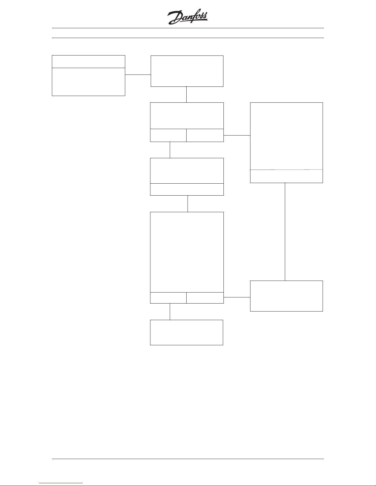
MG.20.B6.02 – VLT is a registered Danfoss trademark
VLT® 2000 Series
100
Is the motor connected
correctly and are all motor
phases ok?
Yes
Factory settings and service
13)
Symptom
Motor stationary, info
in display but no fault
message displayed
Start the VLT frequency
converter by pressing
Start” on the keyboard.
Is the display frozen, i.e. the
display cannot be changed
or is undefinable?
No Yes
Check whether the
following precautions have
been taken!
• Have screened control
cables been used?
• Are the screened cables
connected correctly?
16)15)
14)
17)
18)
The frequency converter
must be set to run using
local references.
The parameter settings
must be changed thus:
parameter 003 = Local
parameter 004 =Change
by means of “+” and “-”.
Does the motor run?
Yes N o
Contact Danfoss.
19)
Check whether the control
signals to the control card
are ok.
20)
Yes
 Loading...