

Page 1
Application Quick Guide
VLT® AQUA Drive FC 200
Page 2

Safet y instruc tions
This Ap plicatio n Quick Gu ide is inten ded only fo r use by train ed specia lists in con junction with the pr oduct manu als
for wor king on VLT® AQUA D rive FC 200 se ries frequ ency conve rters.
Hazar dous volt ages are pre sent in the f requenc y converte r when it is co nnected t o the mains . Incorrec t install ation of th e motor,
frequ ency conve rter or con trol cabl es can cause irreparab le damage t o the frequ ency conve rter or sys tem as well a s serious or f atal
injuri es.
To prevent e lectric al shock, the freque ncy conver ter must b e disconne cted from t he mains be fore perf orming all m aintenan ce work.
The DC li nk capaci tors of the V LT® AQUA Dr ive FC 200 ret ain their c harge for a ve ry long ti me even afte r disconne cting th e mains
suppl y. It is there fore esse ntial to wai t for the dura tion of the period spe cified on t he unit or in t he produc t manual bef ore carry ing out
any mai ntenance wo rk after di sconnec ting the ma ins supply.
Always f ollow the in structi ons contai ned in the re levant pro duct manua ls as well as l ocal and nat ional rul es and safet y regulat ions.
The cont ents of this App lication Qui ck Guide refer m ainly to the bas ic unit of the VLT® AQ UA Drive with gra phical contro l panel
(LCP 102) up to 90 kW (400 V) and ini tial operati on with an asyn chronous moto r. For the sake of cl arity, this App lication Quic k Guide
does no t cover all optio ns and accessor ies or detail ed differences with higher-p ower models o r special vari ants.
Please r efer to the corr esponding pr oduct manua l in all cases.
Page 3

Table of contents
1. Conne ction
1.1 List of power and supply ter minals
1.2 Control term inals in basic un it
(withou t A, B or C option s)
1.3 Function of D IP switches in b asic unit
(withou t A, B or C option s)
1.4 Digital inp ut programmi ng options
2. Opera tion via LCP 102
2.1 Graphical c ontrol unit LCP 102
2.2 Explanati on of LCP 102 status dis play
3. Easy co mmission ing
3.1 Commissioni ng menu (Q2 subme nu of Quick men u)
3.2 Further comm only used par ameters fro m the main menu
3.3 Transf erring unit p arameters us ing the LCP copy fu nction
(Par. 0.50)
3.4 Parameter se tting with M CT 10 softwar e
4. Profib us DP inter face
4.1 General se ttings
4.2 Further set tings
5. Fault an alysis
5.1 Warnings, al arms, and alar m resetting
5.2 If the drive fa ils to restar t after
reset ting an alarm
5.3 Warning and al arm indicatio ns
6. Appli cation exa mples
6.1 Start /stop, four-po le motor, motor t hermistor
6.2 Start /stop, four-po le motor, overs ynchronous ,
motor th ermistor
6.3 Start /stop, two- pole motor, mot or thermisto r
6.4 Start /stop, two- pole motor, over synchrono us,
motor th ermistor
6.5 Start /stop, motor th ermistor
6.6 Fixed sp eeds
6.7 Automat ic fast ramp
6.8 Manual /Off/Automatic sel ection wit h
refere nce value inpu t via keypad
6.9 Manual /Off/Automatic sel ection wit h
refere nce value inpu t via potentio meter
6.10 Manu al Profibus time -out sele ction
6.11 Press ure control in %
6.12 Press ure control in Pa
6.13 Press ure control in b ar with pipe com pensation
6.14 Volum e flow control in m³/h , feedback sig nal
output 0–20 mA
6.15 Volum etric flow contr ol in m³/h, oversy nchronous,
feedb ack signal out put 0–20 mA
6.16 Press ure control in b ar, basic cascad e controller
Page 4
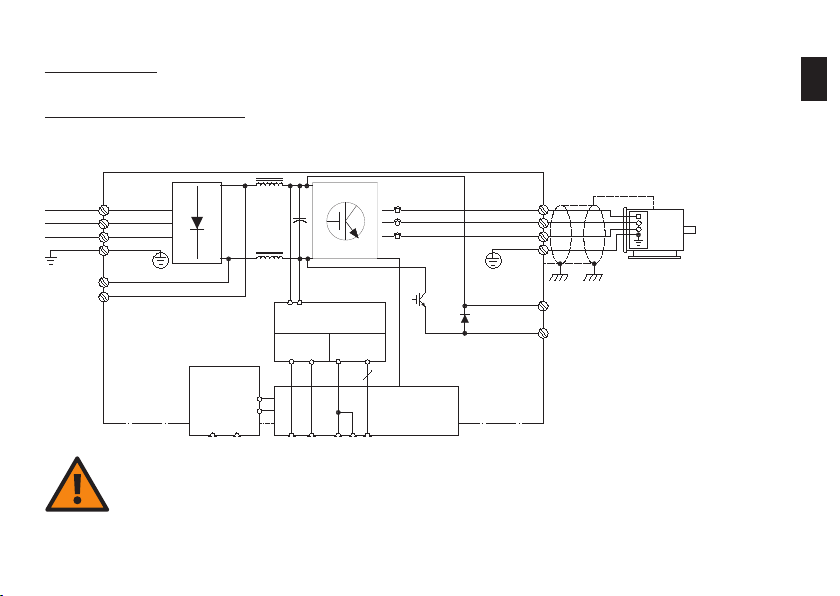
1. Connection
DC-Zwischenkreis
Netz Motor
1.1 Power and sup ply terminals
1
DC link circuitMains
Motor
91 (L1)
92 (L2)
93 (L3)
95
PE
88 (-)
DC-Bus
89 (+)
MCB 107
(Option)
(-)35(+)
36
Integrat ed switch-
Integr. Schaltnetzteil
mode pow er supply
10Vdc
15 mA 200mA
+ - + -
24Vdc
135550 12
Steuerkarte
20
Control
Card
(U) 96
(V) 97
(W) 98
(PE) 99
(R+) 82
(R-) 81
Bremswiderstand
Brake re sistor
(Option)
(option)
Cauti on
The DC l ink capaci tors reta in dangero us DC voltag es for a very long time eve n after di sconnect ing the mai ns supply.
The wai ting time s specifie d on the unit or in the pro duct manua l must be obs erved in any e vent.
For your own safety, o nly use sui table meas uring equ ipment. Fo r example, f or measur ements on fr equency converter s with main s
volta ge of 380 to 48 0 V AC, use mea suring equ ipment rat ed at catego ry III 600 V or better (s ee IEC 61010-1).
Page 5

Termina l no. Descript ion Remar ks
91 (L1), 92 (L2), 93 (L3) Three -phase conn ection for ma ins supply
95 PE conduc tor connec tion Use mini mum 10 mm
96 (W ), 97 (V), 98 (W ) Three-p hase motor con nection See nam eplate for nom inal data
99 PE conduc tor connec tion Equipo tential bondi ng for motor
88 (-), 89 (+)
81 (-), 82 (+) Optional b rake resistor co nnection f or increased d ynamic brak ing Note : maximum vol tage 850–1000 V D C.
35 (-), 36 (+)
Capaci tor-backed DC link circuit int ended for coup ling
severa l drive axes
MCB 107 D optio n: connecti on for optiona l external 24 V p ower
supply f or control ele ctronics ( plug-and- socket connec tor).
Note: m aximum volta ge 850–1000 V DC .
Max. 24 V D C +/- 15%
Max. I nput current 2 .2 A
2. See n ote below.
1
As freq uency conver ters can pro duce earth le akage curren ts greater than 3.5 mA due to the ir mode of oper ation, in accor dance with
EN 50178 an earth co nductor wit h a cross-sec tion of at leas t 10 mm
connec ted.
Warnin g
Termina ls 88/89 for DC link coupl ing can only b e used wit h special ac cessorie s and involve sp ecial saf ety consi deration s. See the
Danfo ss design do cumentat ion for add itional in formatio n.
Using t erminals 81 a nd 82 to incre ase dynam ic braking i s only poss ible with su itable an d correct ly dimensi oned brake r esistors and
involve s special s afety con siderati ons. See th e Danfoss de sign docum entatio n for additi onal infor mation.
2
must be u sed or two sep arately inst alled eart h conductors must be
Page 6
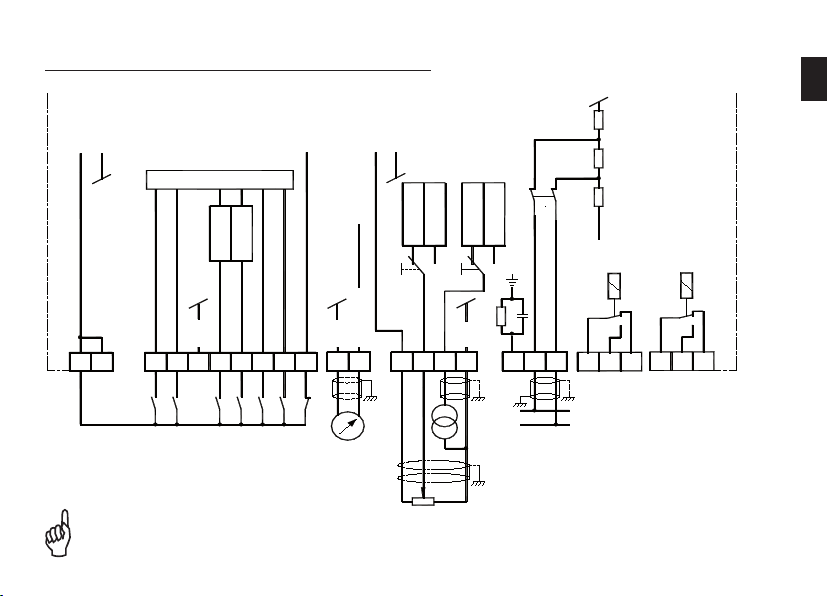
1.2 Cont rol termina ls in basic unit (with out A, B or C opt ions)
12 13 18 19 20 27 29 32 33 39 42
50 53 54 55
61 68 69 01 02 03
-
+
+
-
COM
RS485
0 / 4 - 20 mA
COM
COM
24 V DC
max.200 mA
-+
0 V
5 V
BUS
(P RS-485)
(N RS-485)
37
S 801
P.5 - 02
P.5 - 01
P. 5-00
10 V DC
max.15 mA
+ -
0 - 10 V
0 - 20 mA
0 - 10 V
0 - 20 mA
S202S201
0504 06
Wechsel-
richter
**
Relais 1 Relais 2
** nur beim FC 200 mit Safe Stop
Inverte r
1
See Se ction 1.3 fo r a descript ion of swit ches S201, S202 an d S801.
The ma ximum rate d voltage on a nalogue in puts 53 and 54 i s 20 V.
** only f or FC 200 with sa fe stop
Relay 1 Rela y 2
Page 7

Termina l no. D escripti on Rema rks
12, 13 Interna l +24 V DC sou rce for poweri ng digital inp uts. Maxim um load 200 mA
18 Digita l input (see pa rameter 5-10 for fu nction)
19 Digita l input (see pa rameter 5-11 for func tion)
20
27 Digita l input/outp ut (see parame ters 5-01, 5-12 & 5-30 for f unction)
29 Digita l input/outp ut (see parame ters 5-02, 5 -13 & 5-31 for fun ction)
32 Digita l input (see pa rameter 5-14 for fun ction)
33 Digita l input (see pa rameter 5-15 for fun ction)
37
39 Ground potential for a nalogue outp ut 42
42
50
53, 54
55 Ground potential for a nalogue inpu ts 53 and 54
61 Integr ated RC decoup ling Do not us e
68 (+), 69 (-) RS 485 serial in terface (see parameter 8 -3* for functi on) Max. 115 kbit/s
01, 02, 03 Relay ou tput 1 (see par ameter 5-4 0 [0] for funct ion)
04, 05, 0 6 Relay ou tput 2 (see par ameter 5-4 0 [1] for fu nction)
Refere nce potential (0 V) for exte rnal digital i nput/output
configur ation
Only fo r FC 200 with opti onal safe sto p
Digita l input for saf e stop complia nt with EN 954-1 Cat . 3
or EN 13849-1 SIL 2 (see paramet er 5-19 for functio n)
Scalab le analogue o utput 0/4–20 mA (see parameter 6. 5* for
funct ion)
Interna l +10 V DC power s ource, for exa mple, for supp lying
potent iometer or mot or thermisto r
Analog ue inputs 0–10 V DC o r 0/4–20 mA, selec table
for ref erence/fee dback or motor thermistor
(funct ion: terminal 53, see paramet er 6-1*; terminal 54 , see
parame ter 6-2*;
refere nce, see param eters 3-15, 3-16 & 3-17; feed back, see
parame ter 20-0* ; motor thermi stor, see param eters 1-93 & 1-90)
0–24 V DC, R i = 4 kΩ
< 5 V = logi c “0” (PNP logic)
> 10 V = logic “1” (PN P logic)
Frame po tential for ter minals 12, 13
Input: see terminals 18 and 19
Outpu t: 0/24 V DC, max . 40 mA
Pulse ou tput: see pro duct manual
Input: see terminals 18 and 19
Pulse inp ut: see prod uct guide
To achieve th e safety fun ction, the in formation in t he
design g uide must be ob served.
0/4–20 mA, 50 0 Ω max.
10 V DC, max . 15 mA
0 to +10 V, scalable, R i approx. 10 kΩ;
0 to 20 mA, s calable, Ri a pprox. 200 Ω
V/mA selec tion; see S201/S202
Note: ma ximum voltag e on analogue i nputs
20 V.
Max. 24 0 V AC, 2 A (resistive load)
See the d esign guide fo r further in formation.
1
Page 8
1.3 Function of DIP swi tches in basic unit (without A, B or C optio ns)
Bus term ination
Chang es to DIP swi tch setti ngs become e ffective o nly after s witching off and then o n again.
Current /voltage se lection
termin als 53/54
1
Page 9

1.4 Digital inp ut programming opt ions
Termina l no. Index 18 19 27 29 32 33
Parame ter 5-10 5 -11 5-12 5 -13 5 -14 5-15
Not us ed [0]
Alarm r eset [1]
Coast (i nverse) [2]
Coast /Reset (inve rse) [3]
Quic k stop ramp (inv erse) [4]
DC brak e (inverse) [5]
Stop (in verse) [6]
Ext . interloc k [7 ]
Start [8]
Latch ed start pu lse [9]
Revers ing [10]
Start + reversing [11]
Fixed s peed (jo g) [14]
Fixed r eference e nabled [15]
Fixed r eference b it 0 [16]
Fixed r eference b it 1 [17]
Fixed r eference b it 2 [18]
Store r eference [19]
Store s peed [20]
Spee d up [21]
Spee d down [22]
Set-u p select bi t 0 [23]
Set-u p select b it 1
[24]
3 3 3 3
3 3 3 3 3 3
3 3
3 3 3 3 3 3
3 3 3 3 3 3
3 3 3 3 3 3
3 3 3 3 3 3
3 3 3 3 3 3
x
3 3 3 3 3 3
3
3 3 3 3 3 3
3 3 3
3 3 3 3 3 3
3 3 3 3 3 3
3 3 3 3 3 3
3 3 3 3 3 3
3 3 3 3 3 3
3 3 3 3 3 3
3 3 3 3 3 3
3 3 3 3 3 3
3 3 3 3 3 3
3 3 3 3 3 3
3 3 3 3 3
x
x
3 3 3 3
3 3 3
x
x x
3 3
1
Page 10

Termina l no. Index 18 19 27 29 32 33
Parame ter 5-10 5 -11 5-12 5 -13 5 -14 5-15
Counte r input [ 30] - - -
Pulse i nput [32] - - -
Ramp bi t 0 [3 4]
Mains f ailure (inve rse) [36]
Run Per missive [52]
Manua l Start [53]
Auto st art [54]
DigiP ot Increas e [55]
DigiP ot Decreas e [56]
DigiP ot Clear [57]
Counte r A (+1) [60] - - -
Counte r A (-1) [61] - - -
Reset C ounter A [62]
Counte r B (+1) [63] - - -
Counte r B (-1) [6 4] - - -
Reset C ounter B [65]
Sleep Mode [66]
Reset M aintenan ce Word [78]
Lead Pu mp Start [120]
Lead Pu mp Alterna tion [121]
Pump 1 In terlock [130]
Pump 2 In terlock [131]
Pump 3 In terlock
[132]
3 3 3 3 3 3
3 3 3 3 3 3
3 3 3 3 3 3
3 3 3 3 3 3
3 3 3 3 3 3
3 3 3 3 3 3
3 3 3 3 3 3
3 3 3 3 3 3
3 3 3 3 3 3
3 3 3 3 3 3
3 3 3 3 3 3
3 3 3 3 3 3
3 3 3 3 3 3
3 3 3 3 3 3
3 3 3 3 3 3
3 3 3 3 3 3
3 3 3 3 3 3
[3] = sele ctable; [-] not s electable; [x] = f actory set up. See program ming manual for d etails.
3
3
3
3
3
3
-
-
-
-
-
-
1
3
3
3
3
3
3
Page 11
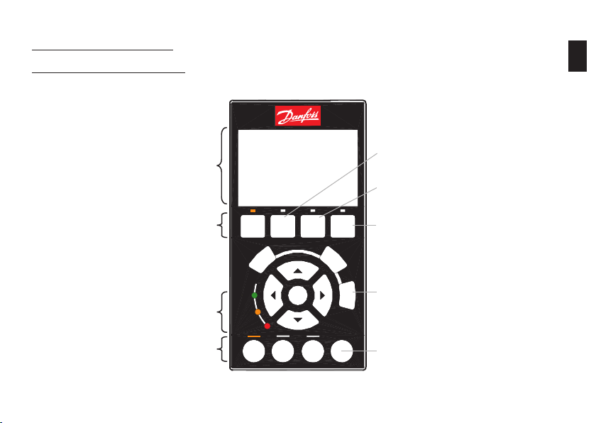
2. Operation via LCP 102
2.1 Graphical control u nit LCP 102
2
Text disp lay
Menu se lection
Status LE Ds
Opera ting mode
On
On
Warn.
Warn
Alarm
Alarm
SStatus
Hand
Accessin g commissioni ng menus
Accessin g parameter m ain menu (all para meters)
Alarm
Main
Quick
Menu
Menu
Back
Cancel
OK
Auto
Off
on
Reset
on
Fault log a nd alarm diagn osis
Log
Online he lp (for each parame ter,
Info
menu item a nd alarm)
Alarm re set (see Sec tion 5.1)
Page 12
SStatus
Quick
Menu
Main
Menu
Alarm
Log
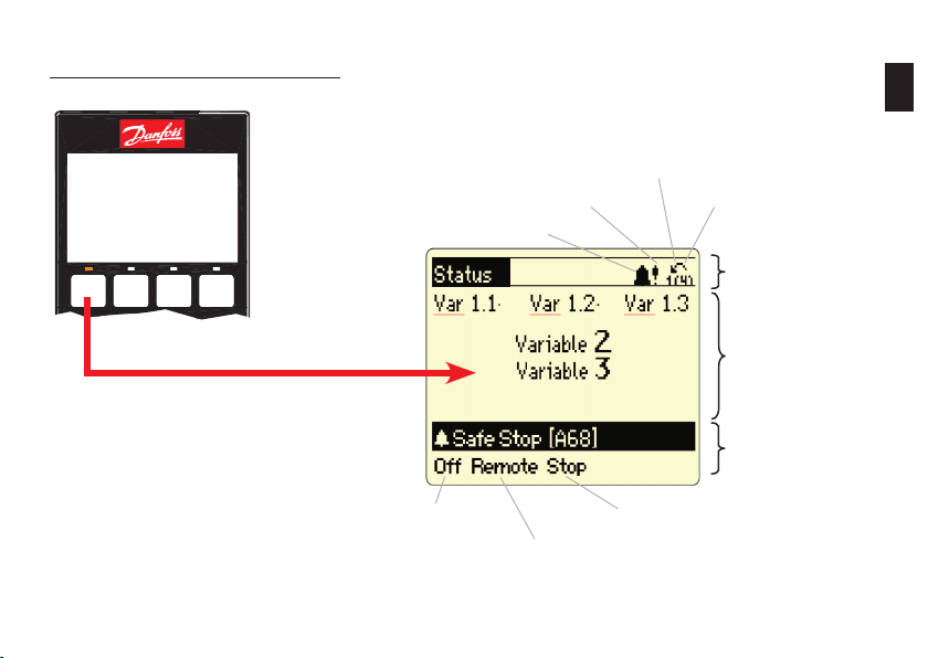
2.2 E xplanation of LCP 102 sta tus display
Alarm
Warning
Direc tion
Parame ter set
(1) = Operation, (4) = P rogram
Status li ne
Opera ting range
Status li ne
2
Opera ting
mode
Opera tional statu s
Refere nce source
Page 13

3. Easy commissioning
3.1 Commiss ioning menu (submen u Q2 of Quick Me nu)
The comm issioning me nu has a set of 11 parame ters that are ne cessary dur ing typica l commissionin g. These par ameters are ar ranged logi cally
instea d of by number. Note : always enter th e parameters in the order sho wn. To access the comm issioning me nu, press the [Qu ick Menu] butto n,
selec t „Q2 commissio ning menu“, and con firm with [OK]. Press the [Status] b utton to retu rn to normal vie w.
Par. Desc ription Setting
0-01 Lan guage Engli sh [0] or set to loc al language
1-20 Mot or power [kW] Accordin g to motor namep late data
1-22 Mot or voltage [ V] Acc ording to motor nameplate dat a
1-23 Mot or frequenc y [Hz] Accordin g to motor namep late data
1-24 Mot or current [A] Accordi ng to motor name plate data
1-25 Rate d motor spee d [rpm] Accordin g to motor namep late data
3-41 Ram p-up time 1 S et ramp-up t ime (accelerat ion time up to rat ed motor spee d)
3-42 Ram p-down tim e 1 Set ram p-down tim e (decelerati on time from ra ted speed to ze ro RPM)
4-12 Min . speed [RPM] Set de sired minimum speed
4-14 Max . speed [RPM] Set des ired maximum s peed
1-29 Auto matic Motor Ada ptation (AMA) AMA is worthwhil e if motor oper ation is unsati sfactor y or additiona l
optimi sation is desir ed.
See the d escription o f AMA in the prod uct guide.
3
Page 14

3.2 Ot her commonly used parame ters in the ma in menu
The fol lowing table lists other pa rameters in t he main menu that are often nec essary in ad dition to the com missioning pa rameters. T he
parame ters in the mai n menu can be acce ssed by pressi ng the [Main Men u] button and se lecting the subgroups.
Par. Desc ription Set ting
1-00 Cont rol response Speed contr ol or PID control
1-03 Loa d torque chara cteristics
1-9* Therm al motor prote ction Motor te mperature mo nitoring, se e descriptio n under 6. App lication exa mples:
3-10 Fixe d references ( 0–7) Use digi tal fixed refe rences
Variabl e reference 1
3-15
Variabl e reference 2
3-16
Variabl e reference 3
3-17
6-1* Analo gue input, ter minal 53 Input signal s caling (curre nt/voltage) a nd the associa ted referenc e and feedbac k values.
6-2* Analo gue input, ter minal 54 Input signal s caling (curre nt/voltage) a nd associate d reference an d feedback va lues.
20- 0* Fee dback Specify fe edback inpu ts and signal ch aracteris tic
20-2* Feedba ck/referen ce
15-0* Operat ing data Display of current ope rating data
15-3* Fault log Read ou t fault log dat a and values
15-4* Type data
14-50 RFI filt er Mu st be disable d if the unit is us ed in an IT net work.
16-** Dat a display
[0] compre ssor torque, [1] squa re-law torq ue, [2] automatic e nergy optim isation CT,
[3] automa tic energy opt imisation V T
Selec t an analogue input, digit al input or bus p ort as the ref erence signal .
See als o descriptio n under 6. Appl ication exam ples:
Specif y signal con ditioning her e when using se veral feedba ck values and /or add itional
refere nce values.
15-43/-45/-51: fre quency conve rter identifi cation. This information i s necessar y for service
querie s.
of all cur rent frequen cy converte r and system da ta (such as refer ence, feedba ck, bus, moto r,
and FC dat a)
3
Page 15

3.3 Using the LCP copy fu nction (paramete r 0-50) to tran sfer device paramet ers
The copy f unction ca n be used to stor e all unit param eters in the LCP 102 con trol panel. T he stored par ameters can b e transferre d to the same
unit of ot her units if ne cessary. The d ata is perman ently stored ( in EEPROM) in the LCP a nd can only be ch anged or dele ted by overwr iting with
new data . The parame ters in the LCP mem ory can only be accessed by l oading them ba ck from the uni t. Parameter 0 -50 can be acce ssed by
pressin g the [Main Menu] b utton and se lecting men u „0-** Ope ration/Dis play“ or „0 -5* Copy/Store“.
Parame ter 0-50 : store in LCP
Parame ter 0-50 : Load from LCP ( All)
Parame ter 0-50 : Load from LCP (o nly Fct.)
No moto r data is tra nsferred if „Load fro m LCP, only Fct.“ is s electe d.
3
Page 16

3.4 Para meter sett ing with MCT 10 softw are
Source a nd system req uirements
Downlo ad the soft ware from the S oftware/ MCT 10 Softw are page at ww w.danfos s.com/drive s
The fre e basic versio n of the MCT 10 sof tware can b e used to archive d ata from and do cument all cur rent Danfoss f requency co nverter seri es. The
CD key req uired for inst allation is 12314500.
Minimu m system requi rements: Pent ium III 350 MHz (or co mpatible), 128 MB RAM , 200 MB free h ard drive space .
Data exc hange with the c onverter
Conver ter -> PC: 1. Con nect the conve rter to the PC
2. Sele ct the conver ter in the net work
3. Sele ct „Copy“
4. Click t he project an d select „A dd“
5. Save the p roject in th e File menu
Access vi a USB port
The conn ection bet ween the conve rter and PC is d etected auto matically. Confi gur ation of the par ameters in th e converter or t he PC softw are is
not nece ssary.
To prevent c urrents fr om fl ow ing in the USB
cable shield due t o potenti al diff erences, t he
conver ter must be a dequate ly earthe d.
PC -> Convert er: 1. Open the s aved fi le
2. Conne ct the conver ter to the PC
3. Sele ct the conver ter in the proje ct
4. Sele ct „Write to freq uency conver ter“
USB
3
Page 17

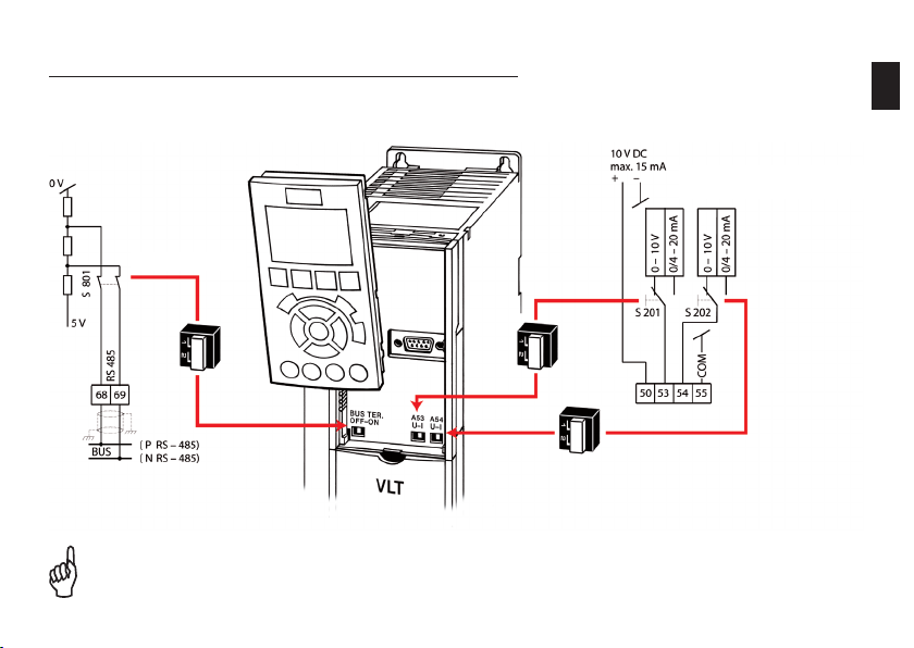
Access via RS-232, Ethernet, or USB Converter
Every D anfoss conver ter has a bus-c apable RS- 485 interf ace. It suppor ts up to 32 netw ork nodes (127 with rep eaters).
For acces s to the interf ace, a suitable converter (RS -232 to RS-485, U SB to RS-485, or Ethernet TCP/IP to RS-485) is necessary.
USB, RS -232, Ether net RS- 485
Inter face conver ter
3
Connec tion
How to con nect
In order to use the conne ction and confi gur e the converter, th e interface s ettings of th e MCT 10 softw are (Communica tion -> Driver menu) m ust
be comp atible (addres s range, COM por t and baud rate). You c an use the Commun ication -> Netwo rk Search menu i tem to look for c onnected
conver ters.
Termina l 68: P (RS- 485)
Termina l 69: N (RS-4 85)
Par. Descript ion Factor y setup
8-31 Address 1
8-32 Baud rat e 9600 baud
Page 18

4. Profibus DP interface
4.1 General settings
Parame ter Descri ption Sett ing
8 - 10 Control Word Profile See PLC
9 - 18 Profibus node address (s et all address DIP switches t o „ON“) 0–125
9 - 22 PPO typ e Automat ic
9 - 63 Baud rat e Automat ic
T he settin gs do not take e ffect unti l the Profib us interf ace
h as been ini tialised (u se paramet er 9-72 to rese t the inter face or
s witch the e xternal 24 V supply off a nd back on).
4.2 Fur ther set tings
Parame ter Descrip tion Sett ing
8 - 01 Con trol Site Activ ate control word
8 - 02 Ac tive control wo rd Option A
8 - 50 … 8 - 56 Prio rities betw een bus/ter minal operat ion (observe p arameter
8 - 03 … 8 - 05 Contr ol word timeo ut (defined resp onse to bus fai lure) Ap plication de pendent
8 - 07 Di agnosis Trigger (d isable in case of doubt) See PLC
9 - 15 … 9 - 16 PCD Co nfiguration See PLC
9 - 27 … 9 - 28 PCW/ PCD enabled/di sabled Enabled
8-01)
Applic ation depen dent
4
Page 19

5. Fault analysis
5.1 Warnings , alarms, and alarm resetting
Warnin g (yellow Warn ing LED on)
A warnin g is an indicati on of a defined s tate. Warning in dications ca n occur during no rmal operat ion; they may
be pure ly informati ve (uncritical) or indicate a po tential probl em. Analyse t he warning bas ed on the displ ayed
warnin g number [Wx xx].
Alarm (r ed Alarm LED b links)
Alarm in dications occ ur when motor o peration has b een inhibite d by the FC 200 for safety reas ons. Analyse
the alar m based on the di splayed alarm number [Axx x]. There are s everal ways to re set alarms tha t are „triplocked “ after the ca use has been re medied:
- [Rese t] button on LCP
- Progra mmed digita l input (see par ameter sett ings in group 5 -1*)
- Automat ic reset func tion (see par ameter sett ings in group 14-2*)
- Reset s ignal via bus in terface (such as RS-485 o r Profibus)
The res et signal r esets the f requenc y converte r after an al arm (trip). Th e button ca n be enable d [1] or dis abled [0] wit h
param eter 0-4 3, “LCP Rese t button”.
Warnin g
Befor e resetti ng an alarm , always dete rmine and re medy the c ause. Rese tting an al arm withou t adequat ely determ ining the c ause can
lead to damage to th e frequen cy convert er or syste m as well as se rious acci dents.
5
Page 20

Trip-l ocked alar m (red Alarm LE D blinks , alarm cann ot be reset , and „Trip-loc k“ is disp layed on the
contr ol panel (if present))
Trip-lo ck is an additi onal protect ive functio n of the VLT® AQUA Driv e and can only be cancelled by
disconn ecting main s power to the uni t. If the unit ha s an external 24 V DC supply (D opt ion), it is only ne cessary
to discon nect the uni t from the mains s upply voltag e. In this case, t he control card remains acti ve (for example ,
to suppo rt fieldbus c ommunicatio n).
The ala rm can be reset a gain as previo usly describ ed after the V LT® AQUA Dr ive FC 200 has be en switched o ff
and on.
If the dis play still show s a trip-lo ck after the un it has been swi tched off (bef ore the alarm is r eset), the unit m ay
have an inte rnal fault. Co ntact your Da nfoss Servi ce provider in t his case.
5.2 If t he drive does n ot restart a fter an alarm reset
An alar m is still di splayed Sett ing
1. Is the alarm t rip-locke d? See des cription in Se ction 5.1.
2. Has the caus e of the alarm be en remedied , or is the alarm
display ed again immed iately afte r it is reset?
3. Is the LCP [Res et] button ena bled? See par ameter 0- 43
An alar m is no longe r displayed S etting
1. Is the LCP [Off ] button ena bled? Press the [Auto-On] but ton to restar t.
2. Is a start s ignal presen t on the digital input or bus inte rface? Check wh ether a star t signal is pres ent on the digi tal input or the
3. Is a referen ce value availa ble on an analo gue or digita l input or
the bus in terface?
4. Is there an op en circuit be tween the fre quency conve rter outpu t
and the m otor?
View th e alarm number s in the fault /alarm log and us e them to
determ ine the cause o f the alarm.
bus.
Check th e reference va lue.
Check th e motor wiring . Is a contacto r or motor switc h present?
5
Page 21

5.3 Warn ing and alarm i ndications
No. Descr iption War ning Alarm / trip A larm / Trip-l ock See par ameter
1 10 V low X
2 Signal faul t (X) (X) 6-01
3 No motor (X) 1-80
4 Mains phase i mbalance (X) (X) (X) 14-12
5 DC link volta ge high X
6 DC link volta ge low X
7 DC overvol tage X X
8 DC underv oltage X X
9 Inverter ove rloaded X X
10 M otor ETR over temperatur e (X) (X) 1-90
11 M otor thermis tor (X) (X) 1-90
12 Torq ue limit X (X) 14-25
13 O vercurrent X X X
14 E arth fault X X X
15 H ardware misma tch X X
16 S hort circui t X X
17 C ontrol word tim e-out (X) (X) 8-04
23 I nternal fan fa ult (X) (X) 14-53
24 E xternal f an fault (X) (X) 14-53
25 B rake resistor shorted X
26 B rake resistor power limit (X) (X) 2-13
27 B rake chopper shorted X X
28 B rake resistor test (X) (X) 2-15
5
Page 22

29 I nverter over temperatur e X X X
30 M otor phase U dro pout (X) (X) (X) 4-58
31 M otor phase V dro pout (X) (X) (X) 4-58
32 M otor phase W dro pout (X) (X) (X) 4-58
33 I nrush fault X X
34 F ieldbus faul t X (X)
36 M ains failure X X
38 I nternal fault X X
40 O verload dig ital output 27 X 5-00, 5-01
41 O verload dig ital output 29 X 5-00, 5-02
42 O verload on di gital outpu t 30-6/30 -7 X
47 24 V s upply low X X X
48 1. 8 V supply low X X
49 S peed limit X
50 A MA calibrati on fault X
51 A MA check Unom a nd Inom X
52 A MA low Inom X
53 A MA motor too bi g X
54 A MA motor too sm all X
55 A MA paramete r out of range X
56 A MA interrupt ed by user X
57 A MA timeout X
58 A MA internal fa ult X X
5
Page 23

59 Cu rrent limit X
60 E xt. interl ock (X) 5-1*
62 O utput frequ ency limit X 4-19
64 M otor voltage X
65 C ontrol board o vertemper ature X X X
66 Temp erature low X
67 N ew options X
68 S afe stop X
69 I nverter over temperatur e X X
70 I nvalid FC config uration X X
79 I nvalid PS config uration X X
80 U nit initialis ed X
92 K . flow X X 22-23
93 D ry pump X X 22-26
94 E nd of curve X X 22-50
95 B roken belt X X 22-60
96 St art delay X 22-75, 22-76
97 St op delay X 22-75, 22-77
98 C lock fault X 0-7*
250
New spar e part
251
New ty pe code
(X) De pendent on pa rameter
5
Page 24

6. Application Examples
6. Application Examples
6. Application Examples
6
This exa mple constitu tes a non-bin ding recomme ndation with r egard
to the Gen eral Deliver y and Warrant y Conditions . It is based on th e
factor y setup and pr esumes that th e motor data has b een confi gured
correc tly. This recomm endation mus t be verifi ed by the u ser.
6.1
Start /stop, four -pole mot or, motor the rmistor
Refere nce 0–50 Hz via t erminal 53; moto r thermistor
monito ring on termin al 19.
Visual a larm indicat ion.
6.1 Sta rt/stop, f our-pole m otor, motor t hermisto r
Refere nce 0–50 Hz via t erminal 53; moto r thermistor
monito ring on termin al 19.
Visual a larm indicat ion.
Start /Stop
Motor the rmistor
Analogu e reference
*Safe sto p as option
Alarm
Relay 1
Motor run ning
Relay 2
This exa mple constitu tes a non-bin ding recomme ndation with r egard
to the Gen eral Deliver y and Warrant y Conditions . It is based on th e
factor y setup and pr esumes that th e motor data has b een confi gured
correc tly. This recomm endation mus t be verifi ed by the u ser.
Par. Func tion Settin g
0-02 Hz/rpm se lection [1] Hz
1-25 Rated motor spe ed s ee motor namep late
5-10 Terminal 18: digital i nput [8] Start *
5-11 Terminal 19: digital input [0] Not used
5-12 Termina l 27: digital input [0] Not use d
1-90 Motor therma l protectio n [2] Thermi stor trip
1-93 Thermistor c onnection [4] Digital inp ut 19
3-15 Variable refere nce 1 [1] Analogue in put 53*
4-53 High speed w arning 1500 rpm
5-40 [0] Relay 1 fun ction [9] Alarm
5-40 [1] Relay 2 func tion [5] Motor run ning
Relevan t parameters
* Factor y setting
6
Page 25

6.2 St art/stop, four-pol e motor, overs ynchrono us, motor t hermisto r
0–72 Hz re ference value v ia terminal 53.
Motor th ermistor mon itoring on ter minal 19.
Visual a larm indicat ion.
6
Start /Stop
Motor the rmistor
*Safe sto p as option
Relay 1
Relay 2
This exa mple constitu tes a non-bin ding recomme ndation with r egard
to the Gen eral Deliver y and Warrant y Conditions . It is based on th e
factor y setup and pr esumes that th e motor data has b een confi gured
correc tly. This recomm endation mus t be verifi ed by the u ser.
Analogu e reference
Alarm
Motor run ning
Par. Func tion Settin g
0-02 Hz/rpm se lection [1] Hz
1-25 Rated motor spe ed s ee motor namep late
5-10 Terminal 18: digital i nput [8] Start *
5-11 Terminal 19: digital input [0] Not used
5-12 Termina l 27: digital input [0] Not use d
1-90 Motor therma l protectio n [2] Thermi stor trip
1-93 Thermistor c onnection [4] Digital inp ut 19
3-03 Max. refe rence 72 Hz
3-15 Variable refere nce 1 [1] Analogue in put 53*
4-14 Max. freque ncy [Hz] 72 Hz
4-53 High speed w arning 2045 rpm
6-15 Ter. 53 scale max. ref/f eedback 72 Hz
5-40 [0] Re lay 1 functio n [9] Ala rm
5-40 [1] Rel ay 2 function [5] Mo tor running
Relevan t parameters
* Factor y setting
Page 26

6.3 St art/stop, two-pol e motor, moto r thermis tor
Refere nce 0–50 Hz via p otentiomet er on terminal 53.
Motor th ermistor mon itoring on ter minal 19.
Visual a larm indicat ion.
Start /Stop
Motor the rmistor
Par. Func tion Settin g
0-02 H z/rpm selec tion [1] Hz
1-25 Rate d motor speed see motor n ameplate
5-10 Termina l 18: digital inpu t [8] St art*
5-11 Terminal 19: di gital input [0] Not us ed
5-12 Terminal 27: di gital input [0] Not us ed
1-90 Mot or thermal pro tection [2] Thermistor t rip
1-93 The rmistor conne ction [4] Digit al input 19
Relevan t parameters
6
Analogu e reference
*Safe sto p as option
Relay 1
Relay 2
This exa mple constitu tes a non-bin ding recomme ndation with r egard
to the Gen eral Deliver y and Warrant y Conditions . It is based on th e
factor y setup and pr esumes that th e motor data has b een confi gured
correc tly. This recomm endation mus t be verifi ed by the u ser.
Alarm
Motor run ning
3-15 Variab le reference 1 [1] Analogue inpu t 53*
4-53 Hig h speed warn ing 3000
5-40 [0] Relay 1 fun ction [9] A larm
5-40 [1] Relay 2 func tion [5] M otor running
* Factor y setting
Page 27

6.4 St art/stop, two-pol e motor, overs ynchrono us, motor t hermist or
0–72 Hz re ference value via terminal 53.
Motor th ermistor mon itoring on ter minal 19.
Visual a larm indicat ion.
6
Start /Stop
Motor the rmistor
Analogu e reference
*Safe sto p as option
Relay 1
Relay 2
This exa mple constitu tes a non-bin ding recomme ndation with r egard
to the Gen eral Deliver y and Warrant y Conditions . It is based on th e
factor y setup and pr esumes that th e motor data has b een confi gured
correc tly. This recomm endation mus t be verifi ed by the u ser.
Alarm
Motor run ning
Par. Func tion Settin g
0-02 H z/rpm selec tion [1] Hz
1-25 Rate d motor speed s ee motor namep late
5-10 Termina l 18: digital inpu t [8] Star t*
5-11 Terminal 19: di gital input [0] N ot used
5-12 Terminal 27: di gital input [0 ] Not used
1-90 Mot or thermal pro tection [2] Thermistor tri p
1-93 The rmistor conne ction [4] Digital input 19
3-03 Ma x. referen ce 72 Hz
3-15 Variab le reference 1 [1] Analogue input 53*
4-14 Max . frequenc y [Hz] 72 Hz
4-53 Hig h speed warn ing 4320 rpm
6-15 Ter. 53 scale m ax. ref/fee dback 72 Hz
5-40 [0] Relay 1 fun ction [9] Alarm
5-40 [1] Relay 2 func tion [5] Motor run ning
Relevan t parameters
* Factor y setting
Page 28

6.5 St art/stop, motor ther mistor
Refere nce 0–50 Hz ter minal 53.
Motor th ermistor mon itoring on ter minal 19.
Visual a larm indicat ion.
6
Start /Stop
Motor the rmistor
Motor the rmistor alar m
Analogu e reference
*Safe sto p as option
Relay 1
Relay 2
This exa mple constitu tes a non-bin ding recomme ndation with r egard
to the Gen eral Deliver y and Warrant y Conditions . It is based on th e
factor y setup and pr esumes that th e motor data has b een confi gured
correc tly. This recomm endation mus t be verifi ed by the u ser.
Alarm
Motor run ning
Par. Func tion Settin g
5-10 Termina l 18: digital inpu t [8] Star t*
5-11 Terminal 19: di gital input [0] N ot used
5-12 Terminal 27: di gital input [0 ] Not used
5-02 Term inal 29 Mode [1] Outp ut
5-31 Termina l 29: digital o utput [60] Comparator 0
1-90 Mot or thermal pro tection [2] Thermistor tri p
1-93 The rmistor conne ction [4] Digital input 19
3-15 Variab le reference 1 [1] Analogue input 53*
5-40 [0] Relay 1 fun ction [9] Alarm
5-40 [1] Relay 2 func tion [5] Motor run ning
Interro gation Alarm 11 (motor t hermistor)
13-10[0] Comparator operand [20] Al arm number
13-11[0] Compar ator functio n [1] ! (equal)*
13-12[0] Comp arator value 11,000
Relevan t parameters
* Factor y setting
Page 29

6.6 Fixed sp eeds
Three d iff erent spe eds (preset r eferences) can b e selecte d
via fl oating cont acts.
Selec t Speed 1
Selec t Speed 2
Selec t Speed 3
*Safe sto p as option
Relay 1
Relay 2
This exa mple constitu tes a non-bin ding recomme ndation with r egard
to the Gen eral Deliver y and Warrant y Conditions . It is based on th e
factor y setup and pr esumes that th e motor data has b een confi gured
correc tly. This recomm endation mus t be verifi ed by the u ser.
Par. Func tion Settin g
0-02 H z/rpm selec tion [1] Hz
5-10 Termina l 18: digital inpu t [8] Star t*
5-11 Terminal 19: di gital input [6] St op (inverse)
5-01 Termi nal 27 Mode [1] Outp ut
5-30 Termi nal 27: digital out put [70] Logic rul e 0
5-13 Terminal 2 9: digital inp ut [16] Preset r ef. bit 0
5-14 Terminal 32: digital inpu t [17] Preset r ef. bit 1
5-15 Terminal 33: digital inpu t [18] Preset r ef. bit 2
13-40[0] Boole an 1 [36] Digital inp ut 29
13-41[0] Logic oper ation 1 [2] OR
13-42[0] Boolea n 2 [37] Digital input 32
13-43[0] Logic op eration 2 [2] OR
13-44[0] Boole an 3 [37] Digital inp ut 33
3-10[1] Preset re f. 1 Desired Speed 1
3-10[2] Preset r ef. 2 Desired Spee d 2
3-10[4] Preset r ef. 4 Desired Spee d 3
Relevan t parameters
Internal logic rule
Referen ces
* Factor y setting
6
Page 30

6.7 Automa tic fast ram p
The sta rts up with f ast accelerat ion and then ru ns with slow
acceler ation. Refe rence 0–1500 rpm via potentiomet er.
6
Start /Stop
Controll er enable
Analogu e reference
*Safe sto p as option
Relay 1
Relay 2
This exa mple constitu tes a non-bin ding recomme ndation with r egard
to the Gen eral Deliver y and Warrant y Conditions . It is based on th e
factor y setup and pr esumes that th e motor data has b een confi gured
correc tly. This recomm endation mus t be verifi ed by the u ser.
Par. Func tion Settin g
5-10 Termina l 18: digital inpu t [8] Star t*
5-11 Terminal 19: di gital input [0] N ot used
5-12 Terminal 27: di gital input [ 2] Coast (inverse)*
5-02 Term inal 29 mode [1] Outpu t
5-31 Termina l 29: digital o utput [16] Under min. spee d
5-15 Terminal 33: digital inpu t [34] Ra mp bit 0
3-15 Variab le reference 1 [1] Analogue input 53*
3-41 Ram p Up 1 „Slo w“
3-42 Ra mp Down 1 „Slow “
3-51 Ramp Up 2 „Fast “
3-52 Ram p Down 2 „Fast“
4-11 Motor s peed low limit 900 rp m
4-52 Mo tor speed low l imit warning 900 rpm
Relevan t parameters
* Factor y setting
Page 31

6.8 Manua l/Off /Autom atic sele ction wit h
refer ence value i nput via key pad
In the sw itch position „ Auto“, the refer ence is active v ia potentiom eter.
In the sw itch position „ Manual“, the re ference can be set using the „Up “ and „Down“ bu ttons.
In the sw itch position „ Off “, the mo tor is stoppe d.
„Auto“ p osition On
„Manual “ position O n
„UP“ but ton
„DOWN“ b utton
Analogu e reference
*Safe sto p as option
Relay 1
Relay 2
This exa mple constitu tes a non-bin ding recomme ndation with r egard
to the Gen eral Deliver y and Warrant y Conditions . It is based on th e
factor y setup and pr esumes that th e motor data has b een confi gured
correc tly. This recomm endation mus t be verifi ed by the u ser.
Par. Func tion Settin g
5-10 Termina l 18: digital inpu t [8] Star t*
5-11 Terminal 19: di gital input [8] St art
5-12 Terminal 27: di gital input [0 ] Not used
5-13 Terminal 2 9: digital inp ut [20] Free ze output
5-14 Terminal 32: digital inpu t [21] Speed u p
5-15 Terminal 33: digital inpu t [22] Spe ed down
3-15 Variab le reference 1 [1] Analogue input 53*
6
Relevan t parameters
* Factor y setting
Page 32

6.9 Manua l/Off /Autom atic sele ction wit h
refer ence value i nput via po tentiome ter
In switc h position „A uto“, the referen ce is active via p otentiomet er.
In switc h position „M anual“, the unit c an only be ope rated via the di splay.
In switc h position „Off “, the m otor is stoppe d.
„Auto“ p osition
„Manual “ position
Par. Func tion Settin g
5-10 Termina l 18: digital inpu t [8] Star t*
5-11 Terminal 19: di gital input [5 4] Auto start
5-12 Terminal 27: di gital input [53] M anual start
Relevan t parameters
6
Analogu e reference
*Safe sto p as option
Relay 1
Relay 2
This exa mple constitu tes a non-bin ding recomme ndation with r egard
to the Gen eral Deliver y and Warrant y Conditions . It is based on th e
factor y setup and pr esumes that th e motor data has b een confi gured
correc tly. This recomm endation mus t be verifi ed by the u ser.
3-15 Variab le reference 1 [1] Analogue input 53*
* Factor y setting
Page 33

6.10 Manua l Profi bus time- out sele ction
With Pro fi bus control , the converter does not accept any commands
via the te rminals. If Pr ofi bus con trol is interr upted, the conve rter
automat ically switc hes to manual mo de (reference s etting via
butto ns). Manual mode c an also be sele cted via ter minal 18.
Manual mo de „On“
Manual „UP “ button
Manual „ DOWN“ butto n
*Safe sto p as option
Relay 1
Relay 2
This exa mple constitu tes a non-bin ding recomme ndation with r egard
to the Gen eral Deliver y and Warrant y Conditions . It is based on th e
factor y setup and pr esumes that th e motor data has b een confi gured
correc tly. This recomm endation mus t be verifi ed by the u ser.
Alarm
Profi bus faul t
Par. Func tion Settin g
1-1* Moto r data see motor n ameplate
8-03 Ctr l. param. for timeout time 1 se c
8-04 T imeout fun ction ctrl . param. [8] Selec t Setup 2
8-05 T imeout End c trl. param. [1] Resume set up*
9-18 Nod e address As requi red
5-10 Termina l 18: digital inpu t [23] Se tup select b it 0
5-40 [0] Re lay functio n [9] Alar m
5-40 [1] Rel ay function [23] Bus OK
0-51 Se tup copy [ 2] Copy to Setup 2
0-10 Acti ve setup [9] Multi Se tup
0-12 Link s etup to [2] Se tup 2
5-11 Terminal 19: di gital input [0] N ot used
5-12 Terminal 27: di gital input [0 ] Not used
5-14 Terminal 32: digital inpu t [0] Not u sed
5-15 Terminal 33: digital inpu t [0] Not u sed
8-01 Co ntrol Site Digital onl y
8-02 Ac tive control p arameter Disab led
5-11 Terminal 19: di gital input [8] St art
5-12 Terminal 27: di gital input [ 20] Freeze outpu t
5-14 Terminal 32: digital inpu t [21] Speed u p
5-15 Terminal 33: digital inpu t [22] Spe ed down
8-01 Co ntrol Site Digital onl y
8-02 Ac tive control p arameter Disab led
Relevan t parameters
Data for b oth setups
Setup se lection
Settin gs only for Set up 1
Settin gs only for Set up 2
* Factor y setting
6
Page 34

6.11 Press ure contro l in %
Pressur e control with in tegrated pro cess controll er.
Interna l reference, f eedback 0–100 % on terminal 54 .
6
Start /Stop
Feedba ck signal
*Safe sto p as option
Relay 1
Relay 2
This exa mple constitu tes a non-bin ding recomme ndation with r egard
to the Gen eral Deliver y and Warrant y Conditions . It is based on th e
factor y setup and pr esumes that th e motor data has b een confi gured
correc tly. This recomm endation mus t be verifi ed by the u ser.
Par. Func tion Settin g
5-10 Termina l 18: digital inpu t [8] Star t*
5-12 Terminal 27: di gital input [0 ] Not used
1-00 Co ntrol mode [3] PI D closed loo p
20-12 Refere nce/feedba ck unit [1] %*
20-21 Refere nce 1 50%
20-94 PID in tegration tim e 0.8
20-0 0 Feedb ack terminal 1 [2] Analogue i nput 54*
6-24 Ter. 54 sca le min. ref/fe edback 0 %*
6-25 Ter. 54 sc ale max. ref/f eedback 100%*
0-20 Display line 1.1 [1601] Referenc e [unit]
0-22 Display line 1.3 [1652] Feedbac k [unit]
Relevan t parameters
Start /Stop
Pressure co ntrol
Feedba ck signal
Display in dication (opt ional)
* Factor y setting
Page 35

6.12 Press ure contro l in Pa
Pressur e control with in tegrated pro cess controll er.
Interna l reference, f eedback 0–20 00 Pa on termin al 54.
6
Start /Stop
Feedba ck signal
*Safe sto p as option
Relay 1
Relay 2
This exa mple constitu tes a non-bin ding recomme ndation with r egard
to the Gen eral Deliver y and Warrant y Conditions . It is based on th e
factor y setup and pr esumes that th e motor data has b een confi gured
correc tly. This recomm endation mus t be verifi ed by the u ser.
Par. Func tion Settin g
5-10 Termina l 18: digital inpu t [8] Star t*
5-12 Terminal 27: di gital input [0 ] Not used
1-00 Co ntrol mode [3] PI D closed loo p
20-12 Refere nce/feedba ck unit [72] Pa
20-21 Refere nce 1 1500 Pa
20-94 PID in tegration tim e 0.8
3-02 Mi n. reference 0 Pa*
3-03 Ma x. referen ce 200 0 Pa
20-0 0 Feedb ack terminal 1 [2] Analogue i nput 54*
6-24 Ter. 54 sca le min. ref/fe edback 0 Pa*
6-25 Ter. 54 sc ale max. ref/f eedback 2000 Pa
0-20 Dis play line 1.1 [1601] Reference [uni t]
0-22 Dis play line 1.3 [1652] Feedback [uni t]
Relevan t parameters
Start /Stop
Pressure co ntrol
Scaling i n Pa
Feedba ck signal
Display in dication (opt ional)
* Factor y setting
Page 36

6.13 Press ure contro l in bar with p ipe compe nsation
Pressur e control using i ntegrated pro cess controll er with pipe
pressur e drop compens ation. Inter nal reference , feedback 0 –10 bar
on termi nal 54.
Start /Stop
Feedba ck signal
*Safe sto p as option
Relay 1
Relay 2
This exa mple constitu tes a non-bin ding recomme ndation with r egard
to the Gen eral Deliver y and Warrant y Conditions . It is based on th e
factor y setup and pr esumes that th e motor data has b een confi gured
correc tly. This recomm endation mus t be verifi ed by the u ser.
Feedba ck 0–20 mA
Par. Func tion Settin g
0-02 H z/rpm selec tion [1] Hz*
5-10 Termina l 18: digital inpu t [8] Star t*
5-12 Terminal 27: di gital input [0 ] Not used
1-00 Co ntrol mode [3] PI D closed loo p
20-12 Refere nce/feedba ck unit [71] bar
20-21 Refere nce 1 5 bar
20-93 PID pr oportiona l gain 0.5
20-94 PID in tegration tim e 0.8
3-02 Mi n. reference 0 ba r*
3-03 Ma x. referen ce 10 bar
20-0 0 Feedb ack terminal 1 [2] Analogue i nput 54*
6-24 Ter. 54 sca le min. ref/fe edback 0 b ar*
6-25 Ter. 54 sc ale max. ref/f eedback 10 bar
22-80 Flow co mpensation [1] Enabled
22-81 Quad. /lin. curv e calculation 100
22-84 Spe ed at no fl ow [Hz] 25 Hz
22-86 Freq. d esign point [H z] 50 Hz
22-87 Pressu re at no-fl ow spe ed 3 bar
0-20 Dis play line 1.1 [1601] Reference [uni t]
0-22 Dis play line 1.3 [1652] Feedback [uni t]
0-24 Disp lay line 3 [1665] Analogue output 42
Relevan t parameters
Start /Stop
Pressure co ntrol
Scaling i n bar
Feedba ck signal
Pipe comp ensation
Display in dication (opt ional)
* Factor y setting
6
Page 37

6.14 Volume fl ow co ntrol in m³/h , feedback signal out put 0–20 mA
Volume fl ow cont rol with integr ated process c ontroller.
Interna l reference, f eedback 0– 5000 m
Feedb ack output 0– 5000 m
3
3
/h on ter minal 54.
/h as 0–20 m A signal on term inal 42.
Par. Func tion Settin g
Relevan t parameters
6
Start /Stop
Feedba ck signal
*Safe sto p as option
Relay 1
Relay 2
This exa mple constitu tes a non-bin ding recomme ndation with r egard
to the Gen eral Deliver y and Warrant y Conditions . It is based on th e
factor y setup and pr esumes that th e motor data has b een confi gured
correc tly. This recomm endation mus t be verifi ed by the u ser.
Feedba ck 0–20 mA
5-10 Termina l 18: digital inpu t [8] Star t*
5-12 Terminal 27: di gital input [0 ] Not used
1-00 Co ntrol mode [3] PI D closed loo p
20-01 Feed back conversi on 1 [1] Square root
20-12 Refere nce/feedba ck unit [25] m
20-21 Refere nce 1 2500 m
20-93 PID pr oportiona l gain 0.5
20-94 PID in tegration tim e 2
3-02 Mi n. reference 0 m
3-03 Ma x. referen ce 500 0 m
20-0 0 Feedb ack terminal 1 [2] Analogue i nput 54*
6-24 Ter. 54 sca le min. ref/fe edback 0 m
6-25 Ter. 54 sc ale max. ref/f eedback 5000 m
6-50 Termi nal 42: analogue output [102] Fee dback 0–20 mA
6-51 Ter. 42 min. s caling 50%
6-52 Ter. 42 max . scaling 75%
0-20 Dis play line 1.1 [1601] Reference [uni t]
0-22 Dis play line 1.3 [1652] Feedback [uni t]
0-24 Disp lay line 3 [1665] Analogue output 42
Start /Stop
Volume fl ow cont rol
3
/h
Scaling i n m
Feedba ck signal
Analogu e output
Display in dication (opt ional)
3
/h
3
/h
3
/h*
3
/h
3
/h*
3
/h
* Factor y setting
Page 38

6.15 Volume tric fl ow control i n m³/h, oversy nchronou s,
feedb ack signal output 0 –20 mA
Volume fl ow cont rol with integr ated process c ontroller.
Interna l reference, f eedback 0– 5000 m
Feedb ack output 0– 5000 m
3
3
/h on ter minal 54.
/h as 0–20 m A signal on term inal 42.
Start /Stop
*Safe sto p as option
Relay 1
Relay 2
This exa mple constitu tes a non-bin ding recomme ndation with r egard
to the Gen eral Deliver y and Warrant y Conditions . It is based on th e
factor y setup and pr esumes that th e motor data has b een confi gured
correc tly. This recomm endation mus t be verifi ed by the u ser.
Feedba ck signal
Feedba ck signal 0–20 mA
Par. Fu nction Sett ing
0-02 Hz/rpm selection [1] Hz
4-14 Ma x. frequen cy [Hz] 72 Hz
5-10 Termi nal 18: digital in put [8] Start *
5-12 Termin al 27: digital inp ut [0] Not used
1-00 Control m ode [ 3] PID closed loo p
20-01 Fe edback conver sion 1 [1] Square root
20-12 Refe rence/feed back unit [25] m
20-21 Ref erence 1 2500 m
20-93 PID proportio nal gain 0.5
20-94 PI D integration time 2
3-02 Min. ref erence 0 m
3-03 Max. re ference 5000 m
20-0 0 Fee dback termin al 1 [2] Analogue in put 54*
6-24 Ter. 54 s cale min. ref/ feedback 0 m
6-25 Ter. 54 s cale max. re f/feedback 5 000 m
6-50 Terminal 42: an alogue outpu t [102] Fee dback 0–20 mA
6-51 Ter. 42 min . scaling 50%
6-52 Ter. 42 max. scal ing 75%
0-20 D isplay line 1.1 [1601] Reference [uni t]
0-22 D isplay line 1.3 [1652] Feedback [un it]
0-24 D isplay line 3 [1665] Analo gue output 42
Relevan t parameters
Start /Stop
Volume fl ow cont rol
3
/h
Scaling i n m
Feedba ck signal
Analogu e output
Display in dication (opt ional)
3
/h
3
/h
3
/h*
3
/h
3
/h*
3
/h
* Factor y setting
6
Page 39

6.16 Press ure contro l in bar, basic c ascade con troller
This exa mple constitu tes a non-bin ding recomme ndation with r egard
Pressur e control with in tegrated pro cess controll er.
The VLT® AQUA D rive cascad e controller ca n switch on add itional
pumps vi a the relays if ne cessary.
Control led variabl e 0–10 bar on termina l 54.
Start ca scade contro l
Coast all p umps
*Safe sto p as option
Control vo ltage pump „1“
Relay 1
Relay 2
This exa mple constitu tes a non-bin ding recomme ndation with r egard
to the Gen eral Deliver y and Warrant y Conditions . It is based on th e
factor y setup and pr esumes that th e motor data has b een confi gured
correc tly. This recomm endation mus t be verifi ed by the u ser.
Start si gnal pump „1“
Control vo ltage pump „ 2“
Start si gnal pump „2“
Par. Func tion Settin g
0-02 H z/rpm selec tion [1] Hz
3-10 Prese t ref. [0] 25%
5-10 Termina l 18: digital inpu t [8] Star t*
5-12 Terminal 27: di gital input [ 2] Coast (inverse)*
1-00 Co ntrol mode [3] PI D closed loo p
20-12 Refere nce/feedba ck unit [71] bar
20-21 Refere nce 1 5 bar
20-93 PID pr oportiona l gain 0.5
20-94 PID in tegration tim e 0.8
3-02 Mi n. reference 0 ba r*
3-03 Ma x. referen ce 10 bar
20-0 0 Feedb ack terminal 1 [2] Analogue i nput 54*
6-24 Ter. 54 sca le min. ref/fe edback 0 b ar
6-25 Ter. 54 sc ale max. ref/f eedback 10 bar
20-73 Min. fe edback leve l 0 bar
20-74 Maximu m feedback le vel 10 bar
25-0 0 Casca de controller [1] Enable d
25-05 Pres et control gro up [1] Yes*
25-0 6 Numbe r of pumps [1] 3 pumps
25-45 Switc h-on thresh old [Hz] 45 Hz*
5-40 [0] Re lay 1 functio n [212] Casc. p ump 2**
5-40 [2] Re lay 2 functio n [213] Casc. p ump 3**
Relevan t parameters
Start /Stop
Pressure co ntrol
Scaling i n bar
Feedba ck signal
Cascad e controller
Relay
* Factor y setting
6
Page 40

If you have any questions or need additional assistance, contact your authorised retailer or
designated contact person.
The current contact data can be found on the website of the appropriate country or under
Contact at ww w.danfoss.com.
PB.14.H1.02
VLT® is a trademark of Danfoss A/S Produced by KKM 2010.03
 Loading...