

Page 1
Data sheet
Seated valves (PN 6)
VL 2 – 2-way valve, ange
VL 3 – 3-way valve, ange
Description
Ordering
Example:
2-way valve; DN 15; kVS 1,6; PN 6;
T
120 °C; flange connection
max
- 1× VL 2 DN 15 valve
Code No.: 065Z0373
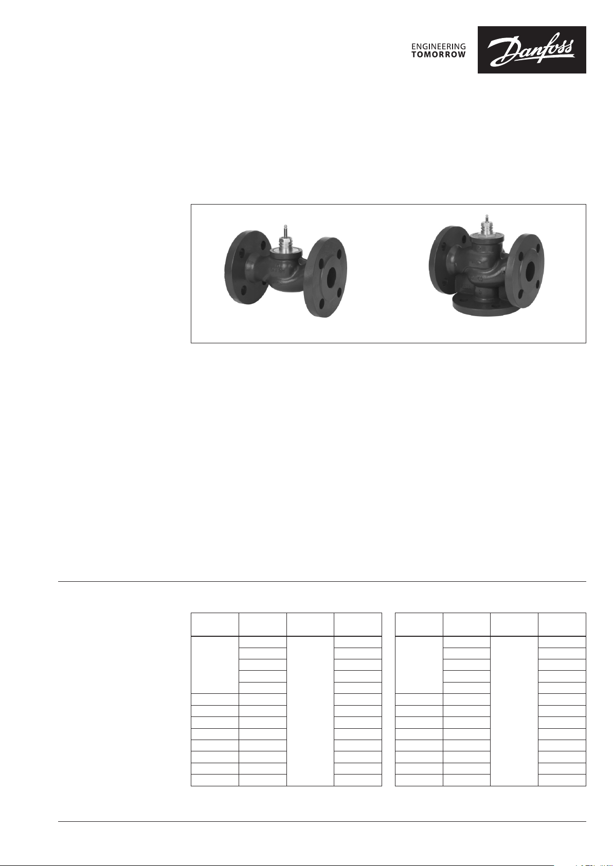
VL 2
VL 2 and VL 3 valves provide a quality, cost
effective solution for most water and chilled
applications.
The valves are designed to be combined with
following actuators:
• DN 15-50 with AMV(E) 335, AMV(E) 435 or
AMV(E) 438 SU actuators.
With AMV(E) 25 (SU/SD) or AMV(E)
35 actuators (with adapter
065Z0311).
• DN 65-80 with AMV(E) 335 or AMV(E) 435
actuators. With AMV(E) 56 actuator
(with adapter 065Z0312).
• DN 100 with AMV(E) 55 or AMV(E) 56,
AMV(E) 655, AMV(E) 658 SU/SD or
AMV(E) 659 SD actuators.
Combinations with other actuators could be
seen under Accessories.
2-way valve VL 2
k
DN
15
20 6.3 065Z0376
25 10 065Z0377
32 16 065Z0378
40 25 0 65Z0379
50 40 065Z0380
65 63 065Z0381
80 100 065Z0382
100 145 065Z3426
VS
(m3/h) (oC)
0.63
1.0 065Z0372
1.6 065Z0373
2.5 06 5Z0374
4.0 065Z0375
T
120
max
Code No.
065Z0371
VL 3
Features:
• Bubble tight design DN 15-80
• Snap mechanical connection together with
AMV(E) 335, AMV(E) 435
• Dedicated 2 and 3-port valve
• Suitable for diverting applications (3-port)
Main data:
• DN 15 -10 0
• kVS 0,63-145 m3/h
• PN 6
• Temperature:
- Circulation water/glycolic water up to 50 %:
2 (–10 1)) … 120 °C
1)
At temperatures from –10 °C up to +2 °C use stem
heater
• Flange PN 6 connections
3-way valve VL 3
k
DN
15
20 6.3 0 65Z0356
25 10 065Z0357
32 16 065Z0358
40 25 065Z0359
50 40 065Z0360
65 63 065Z0361
80 100 065Z0362
100 145 06 5Z3413
VS
(m3/h) (oC)
0.63
1.0 065Z0352
1.6 065Z0353
2.5 0 65Z0354
4.0 065Z0355
T
120
max
Code No.
065Z0351
© Danfoss | 2021.06 AI133286476129en-010803 | 1
Page 2
Data sheet Seated valves VL 2, VL 3
Ordering (continued)
Accessories - Adapter
DN Actuators
15- 50 AMV(E) 25, 35 4.0 06 5Z03 11
65-80 AMV(E) 56 2.5 065 Z0312
max. ∆p
(bar)
Code No.
Accessories - Stem heater
DN Actuators
15- 80 AMV(E) 335, 435
15- 50 AMV(E) 438 SU enclosed
15- 50 AMV(E) 25/35 06 5Z03 11
65-80 AMV(E) 56 06 5Z0312
100 AMV(E) 55, 56, 65x 24/15 065Z7020 /
Power supply Code No. Code No.
(V/ VA) Stem Heater Adapter
24/40 065Z0 315
Service kits
Typ e DN Code No.
15 065Z0321
20 065Z0322
25 065Z0323
Stuffing box
32 065Z0324
40/50 065Z0325
65/80 065Z0327
100 065B13 60
/
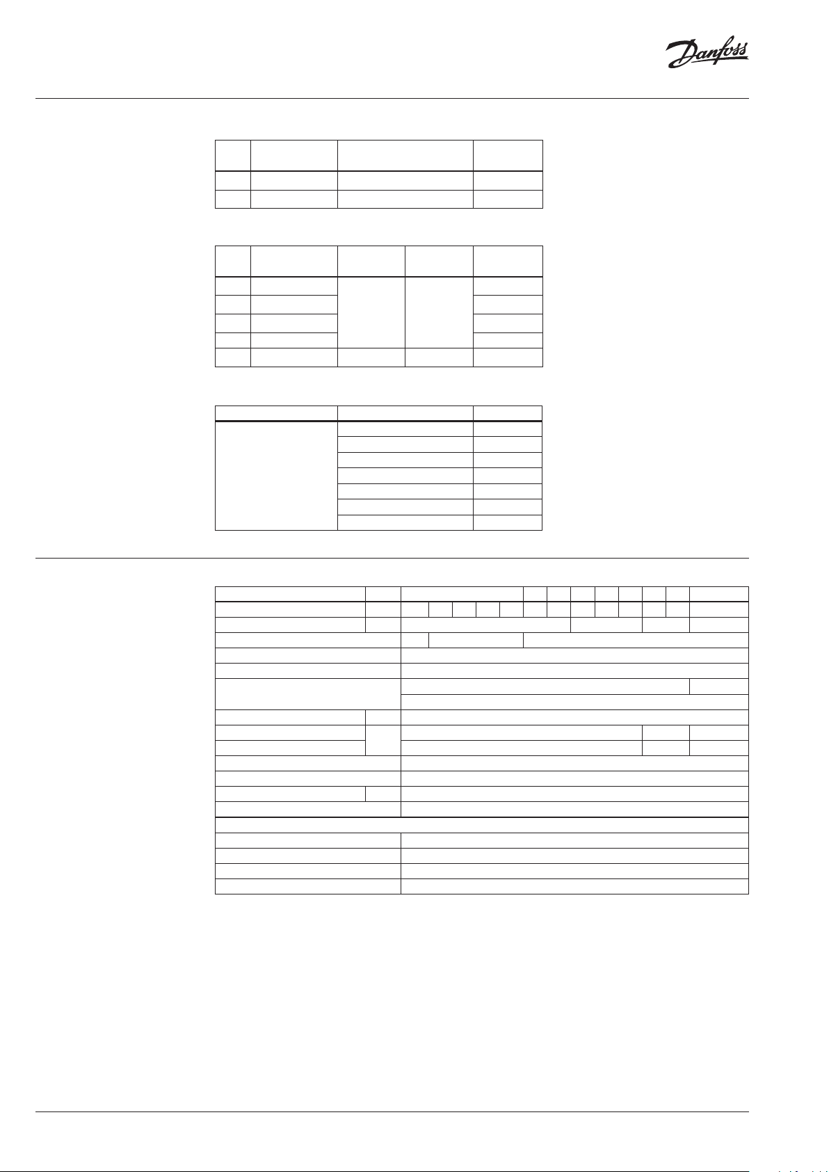
Technical data
Nominal diameter DN 15 20 25 32 40 50 65 80 10 0
k
value m3/h 0.63 1.0 1.6 2.5 4.0 6.3 10 16 25 40 63 100 145
VS
Stroke mm 10 15 20 30
Control range 30:1 50:1 100 :1
Control characteristic LOG: port A-AB; LIN: port B-AB
Cavitation factor z ≥ 0,4
Leakage
A - AB bubble tight design 0.05 % of k
B - AB ≤ 1.0 % of kVS
Nominal pressure PN 6
Max. closing pressure 1) (mixing)
Max. closing pressure 1) (diverting) 1 0.6 0.3
bar
4 2.5 1.0
Medium Circulation water / glycolic water up to 50 %
Medium pH Min. 7, Max. 10
Medium temperature
o
C 2(–10
3)
) … 120
Connections Flange PN 6 acc. to EN 1092-2
Materials
Valve body Grey cast iron EN-GJL-250 (GG-25)
Valve stem Stainless steel
Valve cone Brass
4)
Stuffing box sealing EPDM
1)
Maximum p ermissible differe ntial pressure across the valve ref fered for the whole ac tuating range of motorised val ve (a function of
actuator’s performance)
2)
for actuato r AMV(E) 55
3)
At temperature s from −10 up to +2 °C use stem heater
4)
At DN 100 red b ronze CuSn5Zn5Pb5 (Rg 5)
VS
2)
2)
2 | AI133286476129en-010803 © Danfoss | 2021.06
Page 3
Data sheet Seated valves VL 2, VL 3
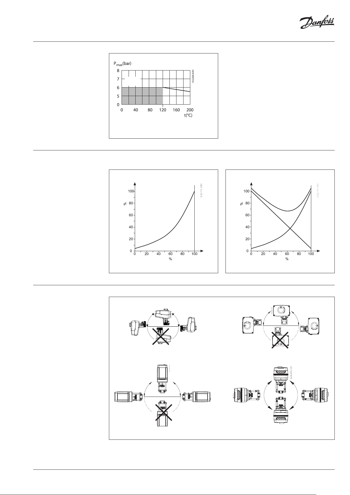
Pressure temperature
diagram
PN 6
EN -G JL-2 50
(GG -25)
Maximum allowed operating pressure as a function of
medium temperature (anges according to EN 1092-2).
Valve characteristics Valve characteristics log (2-way) Valve characteristics log/lin (3-way)
A+BAB
B
Cappacity
B
A
A
Cappacity
AB
B
A
A
Installation
AMV(E) 335/435
Stroke
Stroke
AMV(E) 25(SU/SD)/35/438 SU
AMV(E) 55/56
AMV(E) 65x
AI133286476129en-010803 | 3© Danfoss | 2021.06
Page 4
Data sheet Seated valves VL 2, VL 3
Valve mounting
Before valve mounting the pipes have to be
cleaned and free from abrasion. Valve must
be mounted according to flow direction as
indicated on valve body. Mechanical loads of the
valve body caused by the pipes are not allowed.
Valve should be free of vibrations as well.
Installation of the valve with the actuator is
allowed in horizontal position or upwards.
Installation downwards is not allowed.
Always install the valve with the arrow on
the body in the same direction as the flow. In
order to avoid turbulence, which will affect the
measuring accuracy, it is recommended to have a
straight length of pipe up and down stream from
the valve as shown (D - diameter of pipe).
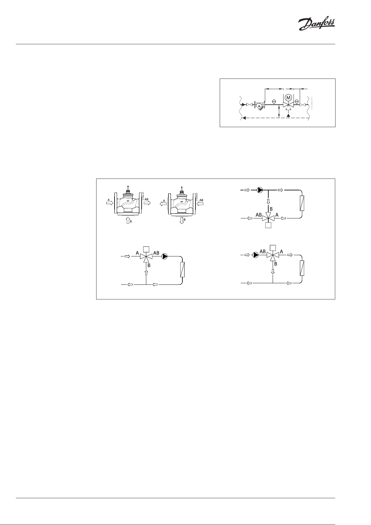
Mixing
Fig. 1: Mixing or diverting connection
Diverting
Note:
Install a strainer upstream of the valve (e.g. Danfoss FVR/
FVF)
5D
FVR/FVF
Fig. 3: Mixing valve used in diver ting application
2D
AMV(E)
5D
Fig. 2: Mixing valve used in mixing application
Mixing or diverting connection
3-way valve can be used either as mixing or
diverting valve (fig.1).
If 3-way valve is installed as mixing valve
meaning that A and B ports are inlet ports, and
AB port is outlet port it can be installed in mixing
(fig.2) or diverting application (fig.3).
3-way valve can be also installed as diverting
valve in diverting application (fig.4) meaning that
AB port is inlet and A and B ports are outlets.
Fig. 4: Diverting valve used in diverting application
Note:
Maximal closing pressure for mixing and
diverting installation are not the same. Please
refer to values stated in Technical data section.
4 | AI133286476129en-010803 © Danfoss | 2021.06
Page 5

Data sheet Seated valves VL 2, VL 3
21
1
pp
p
a authority, Valve
5.0
p2
p
a
2
1
=
∆×
∆
=
62.0
557.90
7.90
authority valve hence
50.39
5536
36
authority valve hence
Sizing
Flow Rate
(liquid with specific a gravity of 1)
l/sec m3/h
max
Δp
FLOW Pressure drop kPa (100 kPa = 1bar = ~ 10 m H2O)
Example
Design data:
Flow rate: 6 m3/h
System pressure drop: 55 kPa
Locate the horizontal line representing a flow
rate of 6 m3/h (line A-A). The valve authority is
given by the equation:
Where:
Δp1 = pressure drop across the fully open valve
Δp2 = pressure drop across the rest of the circuit
with a full open valve
The ideal valve would give a pressure drop equal
to the system pressure drop (i.e. an authority of
0,5):
if:
Δp1 = Δp
2
In this example an authority of 0,5 would be
given by a valve having a pressure drop of
55 kPa at that flow rate (point B). The intersection
of line A-A with a vertical line drawn from B lies
between two diagonal lines; this means that no
ideally-sized valve is available.
The intersection of line A-A with the diagonal
lines gives the pressure drops stated by real,
rather than ideal, valves. In this case, a valve with
kVS 6,3 would give a pressure drop of 90,7 kPa
(point C):
The second largest valve, with kVS 10, would give
a pressure drop of 36 kPa (point D):
Generally, for a 3 port application, the smaller
valve would be selected (resulting in a valve
authority higher than 0,5 and therefore
improved control). However, this will increase
the total pressure and should be checked by the
system designer for compatibility with available
pump heads, etc. The ideal authority is 0,5 with a
preferred range of between 0,4 and 0,7.
AI133286476129en-010803 | 5© Danfoss | 2021.06
Page 6

Data sheet Seated valves VL 2, VL 3
Design
(Design variati ons are possible)
VL 2 DN 15-80
1. Valve body
2. Valve insert
3. Valve cone
4. Valve stem
5. Moving valve seat
(pressure relieved)
6. Stuffing box
VL 3 DN 15-80
1. Valve body
2. Valve insert
3. Valve cone
4. Valve stem
5. Valve seat
6. Pressure relieve chamber
7. Stuffing box
VL 2 DN 100
1. Valve body
2. Valve insert
3. Valve cone
4. Valve stem
8. Blind flange
VL 3 DN 100
1. Valve body
2. Valve insert
3. Valve cone
4. Valve stem
6 | AI133286476129en-010803 © Danfoss | 2021.06
Page 7

Data sheet Seated valves VL 2, VL 3
Dimensions
min. 20,5
45°
1
H
k
H
d2
n
L
H
min . 100
L
VL 2 (DN 15-80) AMV(E) 335, 435 + AMV(E) 438 SU +
VL 2 (DN 15-80) VL 2 (DN 15-50)
AMV(E) 25 (SU/SD),35 +
VL 2 (DN 15-50) +
adapter 065Z0311
mi n. 150
2
H
H
3
H
H
L
AMV(E) 56 +
VL 2 (DN 65-80) +
adapter 065Z0312
Typ e DN
VL 2
Note:
If stem heater is use d dimension H1 is increased for 28 m m and H2 for 32 mm.
L H H1H2H3k d2
mm (kg)
15 130 40 191 216 - 55 11 4 1.48
20 150 45 194 218 - 65 11 4 2.07
25 160 50 197 222 - 75 11 4 2.59
32 180 60 202 226 - 90 14 4 3.82
40 200 65 213 237 - 100 14 4 5.28
50 230 70 218 242 - 110 14 4 6. 74
65 290 88 254 - 428 130 14 4 13.90
80 310 95 258 - 432 15 0 19 4 17.2 2
Weight
n
AI133286476129en-010803 | 7© Danfoss | 2021.06
Page 8

Data sheet Seated valves VL 2, VL 3
Dimensions (continued)
min. 20,5
45°
1
k
H
d2
n
L
H H
min . 100
L
VL 3 (DN 15-80) AMV(E) 335, 435 + AMV(E) 438 SU +
VL 3 (DN 15-80) VL 3 (DN 15-50)
AMV(E) 25 (SU/SD),35 +
VL 3 (DN 15-50) +
adapter 065Z0311
2
H
H
3
H
H
L
AMV(E) 56 +
VL 3 (DN 65, 80) +
adapter 065Z0312
Typ e DN
VL 3
Note:
If stem heater is use d dimension H1 is increased for 28 m m and H2 for 32 mm.
L H H1H2H3k d2
mm (kg)
15 130 63 191 216 - 55 11 4 1.93
20 150 70 19 4 218 - 65 11 4 2.68
25 160 75 197 222 - 75 11 4 3.59
32 180 80 202 226 - 90 14 4 5.17
40 200 90 230 255 - 10 0 14 4 7.0 8
50 230 100 243 267 - 110 14 4 10. 11
65 290 120 254 - 428 13 0 14 4 16.15
80 310 155 270 - 432 150 19 4 22.36
Weight
n
8 | AI133286476129en-010803 © Danfoss | 2021.06
Page 9

Data sheet Seated valves VL 2, VL 3
Dimensions (continued)
d2
k
45°
d2
k
H
n
45°
VL 2 (DN 100) VL 3 (DN 100)
mi n. 150
1
H
3
H
H
n
min . 81
4
H
3
H
L
AMV(E) 55, 56 +
VL 2, VL 3 (DN 100)
Typ e DN
VL 2
VL 3 175 34.0
Note:
If stem heater is use d dimension H remains the sam e.
100 350
L H H1 H2 H3 k d2
mm (kg)
196
406 317 450 170 18 4
L
AMV(E) 65x +
VL 2, VL 3 (DN 100)
n
Weight
39.0
AI133286476129en-010803 | 9© Danfoss | 2021.06
Page 10

Data sheet Seated valves VL 2, VL 3
10 | AI133286476129en-010803 © Danfoss | 2021.06
Page 11

Data sheet Seated valves VL 2, VL 3
AI133286476129en-010803 | 11© Danfoss | 2021.06
Page 12

Data sheet Seated valves VL 2, VL 3
© Danfoss | DCS-S/SI | 2021.0612 | AI133286476129en-010803
 Loading...