

Page 1

User Guide
Visual Chiller
for small units ready to be customized
Software Version 1.07
Page 2

C ontents
User Interface ...............................................................................3
Main screen, Keyboard, Status, Alarm, Login, Start, Parameters,
I/O display, I/O Config, Service, Language, About ........................ 3
Regulation set point ................................................................................ 3
Parameters ...................................................................................8
SetUp: ...........................................................................................8
Parameter: y01, y03, y07,Cid ................................................................ 8
Buzzer and relay ..........................................................................9
Parameter: BUZ, Adl, AOF ..................................................................... 9
Serial setting ................................................................................9
Parameter: Cid, Ser, bAU, COM ............................................................ 9
Password ......................................................................................9
Parameter: L01, L02, L03 ........................................................................ 9
Unit Configuration .....................................................................10
Parameter: H06, H40, HEA ...................................................................10
Temperature Control .................................................................11
Parameter: rEG, rET, Sc1, rC1, SH1, rH1, SdC, SdH, rin, SOE, SOO
11
Maximum number of compressor starts per hour: .................13
Parameter: CT0, CT1, CT2, CT3, CT4, CT5, CT6, CT7 ...................13
Inverter compressor ..................................................................14
Parameter: IV0, IV1, IV2, IV4, IV5 ........................................................14
Pump for the internal coil: ........................................................15
Parameter: P01, P02, AFr ......................................................................15
Valve in the liquid line ...............................................................16
Parameter: Pd1, Pd2, Pd3, Pd4............................................................16
Reversing cycle valve (4-way valve): ........................................17
Parameter: rE1 ..........................................................................................17
Compressor’s status ...............................................................................17
Defrost: .......................................................................................18
Parameter: d01, d02, d09, d10, d13, d14, d15, d16, d20, d21 18
Stepper motor valve setting for SuperHeat control: ..............19
Parameter: EEN, bAt, v10, EV0, EV1, EV2, EV3, EV4, EV5, EV6,
EV7, EV8, EV9 ........................................................................................... 19
SuperHeat control:: ...................................................................20
Parameter: SH0, N22, N10, N09, N19, N04, N20, N05, N11, N18,
N32, N17, N15, N21, o30 ...................................................................... 20
External coil ...............................................................................22
Parameter: F01, F02, FCS, FCD, FCi, FCd, FHS, FHD, FHi, FHd, .22
Stepless regulation of the fan: .................................................23
Parameter: F11, F12, F13 .....................................................................23
Heaters: ......................................................................................24
Parameter: HE1, HE2, HE3, HE4, HE5 ................................................24
ICE alarm: ...................................................................................25
Parameter: AIT, AID, AIA ........................................................................25
High pressure alarm: .................................................................26
Parameter: HPE, HPS, HPD ...................................................................26
Pressure alarms from analogue input:.....................................27
Parameter: Alr, AL1, LPC, ALE, LPS, LPD ..........................................27
Compressor high temperature alarms: ...................................28
Parameter: HT0, HT1, HT2 ....................................................................28
How to log data into SD card: ...................................................28
Parameter: SDL ........................................................................................28
Status variables: ........................................................................32
Software status: ....................................................................................... 32
Status: V01,…,V08, …, V11, …,V20, V22, V24, V26, V28, V29,V31,
V34, …, V37,…, V40,V43, V44,V53, …,V57, V59, …, V61, V65,
V67, V68, V72, V75, V81,…, V83, V85 C01,…, C04 ........................ 32
Preparatory, see
MCX Shape user guide: DKRCC.PS.RJ0.E3.02
MCXDesign manual: DKRCC.PS.RI0.Y3.02
2 RS8KB102 © Danfoss 2018-06 Visual Chiller
Page 3
User Interface
Main screen, Keyboard, Status, Alarm, Login, Start,
Parameters, I/O display, I/O Config, Service, Language,
About
The user interface has been developed for LCD displays.
Note: playing with MCXShape, it is very easy to customize
the structure and the visibility of the menu: so the following
indication cannot match with all the compiled software
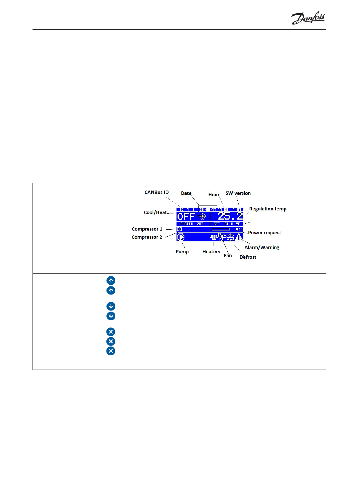
Main screen
Keyboard
Regulation set point
: Scroll UP, increase a value
: 3s when in main screen: toggle ON/OFF
: Scroll down, decrease a value
: 3s when in main screen: toggle Heat/Cool mode
: exit and save,
: when in main screen: access the active alarm list
: 3s when in Alarm screen: manual reset
The LEFT and RIGHT keys, if present, allow you to move the cursor to the desired option
Visual Chiller RS8KB102 © Danfoss 2018-06 3
Page 4
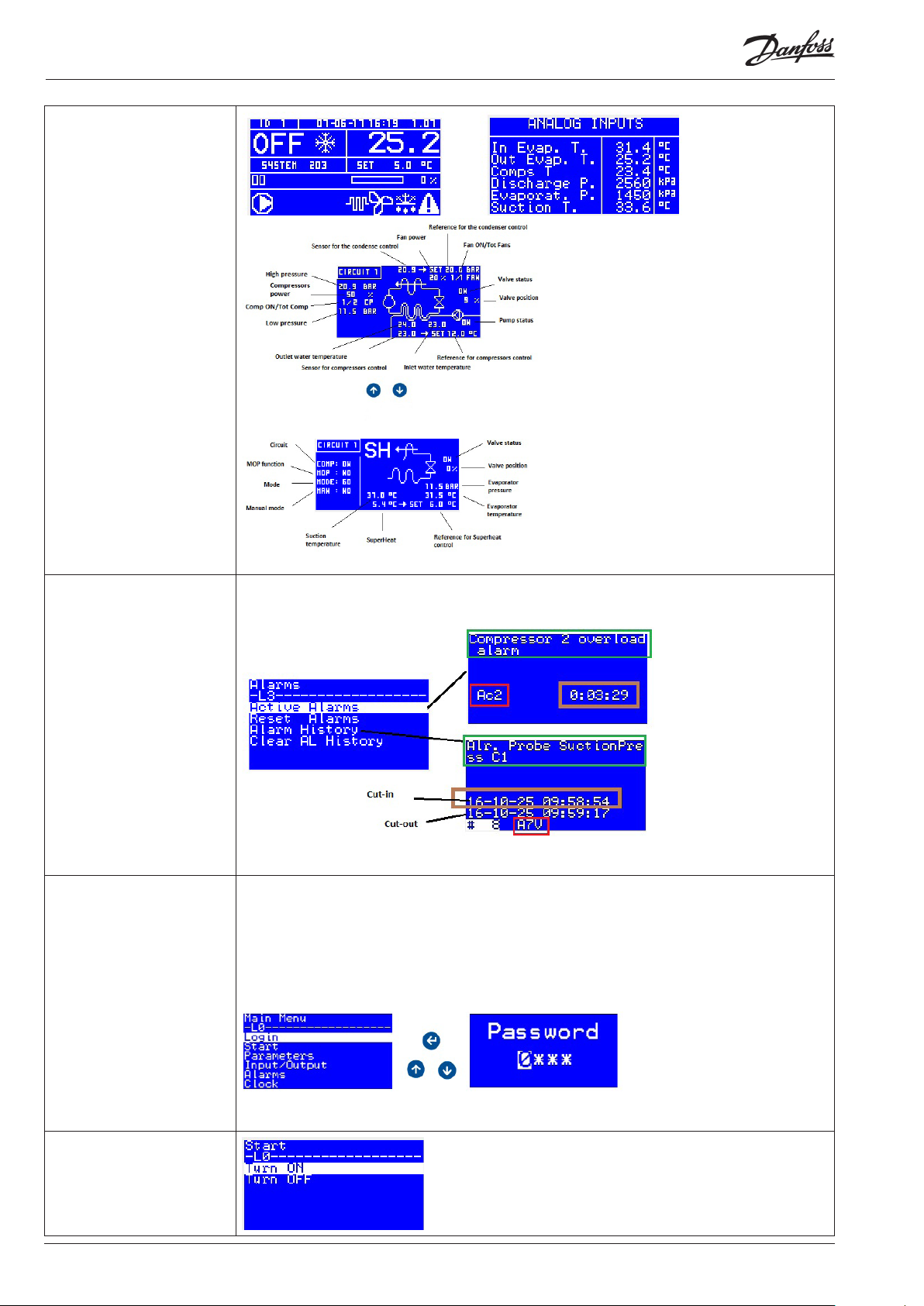
Menu Screen: Status
Menu: Alarm Each alarm is described through an alarm description (for LCD display only), an alarm code and
the time since its activation in the format hours:minutes:seconds (seconds for LCD display only).
Note: You can also access alarm visualization by pressing the ESC key from the main screen.
The alarm is only reset if the alarm has ended and it will return you to the main screen.
Note: Alarms can also be reset by pressing ESC for 3 seconds on the alarm screens
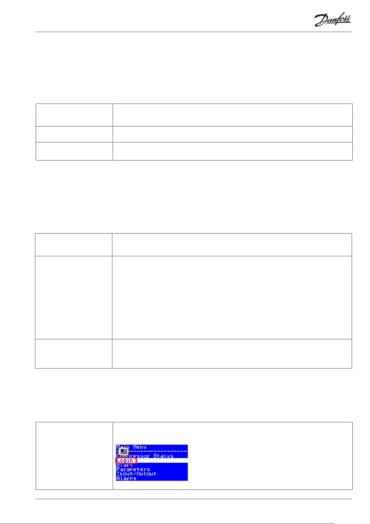
Menu: Login Parameters and Menu are organized into 4 access levels. Levels from 1 to 3 are linked to a password.
Elements cannot be accessed when they are on a higher level than the entry level. The level of each
parameter and menu is defined with MCXShape
• Level 0 is accessible without password
• Levels 1-3 are linked to a password (Check parameters L01, L02 and L03)
• Level 4 is not linked to a password, which can be used to make a menu or parameters
never accessible.
You can log in from the menu:
if the password provided is not correct you remain on the login screen. Otherwise you return to the
main menu.
Menu: Start
4 RS8KB102 © Danfoss 2018-06 Visual Chiller
Page 5
Menu: Parameter This menu contains all the parameters.
The meanings of the parameters are explained in the last part of this manual
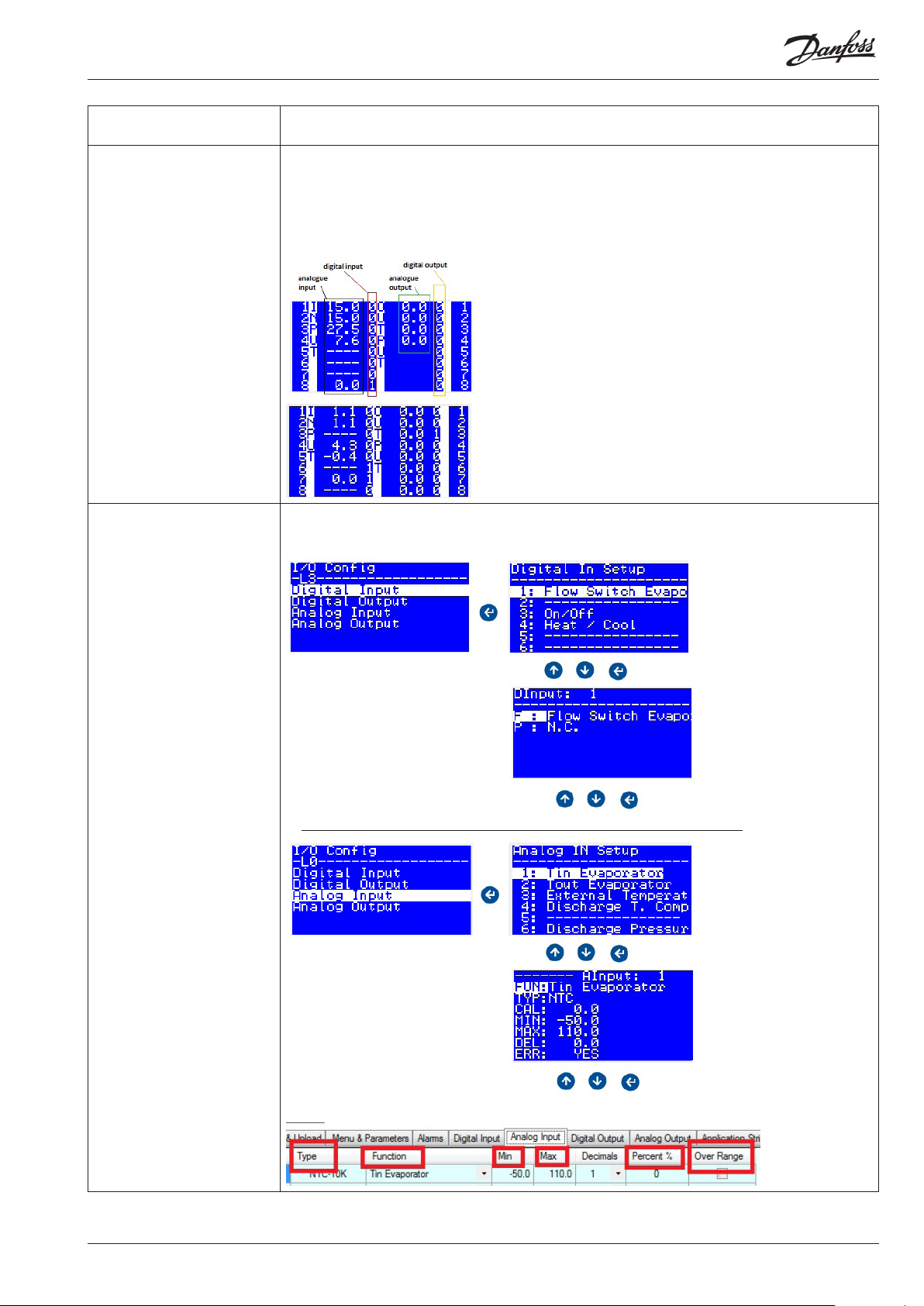
Menu: I/O Display Display input and output values
You have access to three screens showing all the input and output values; each screen shows a group
of 8 I/Os. Use UP and DOWN keys to scroll.
The second and third screens are used with MCX15 and MCX20 only.
The example below shows the first screen.
Menu: I/O Config From the menu I/0 Config it is possible to change the position of all the inputs and outputs used
in the software
Note: “CAL”is the offset to add of the reading, the other items are the ones available in the MCXShape
Visual Chiller RS8KB102 © Danfoss 2018-06 5
Page 6
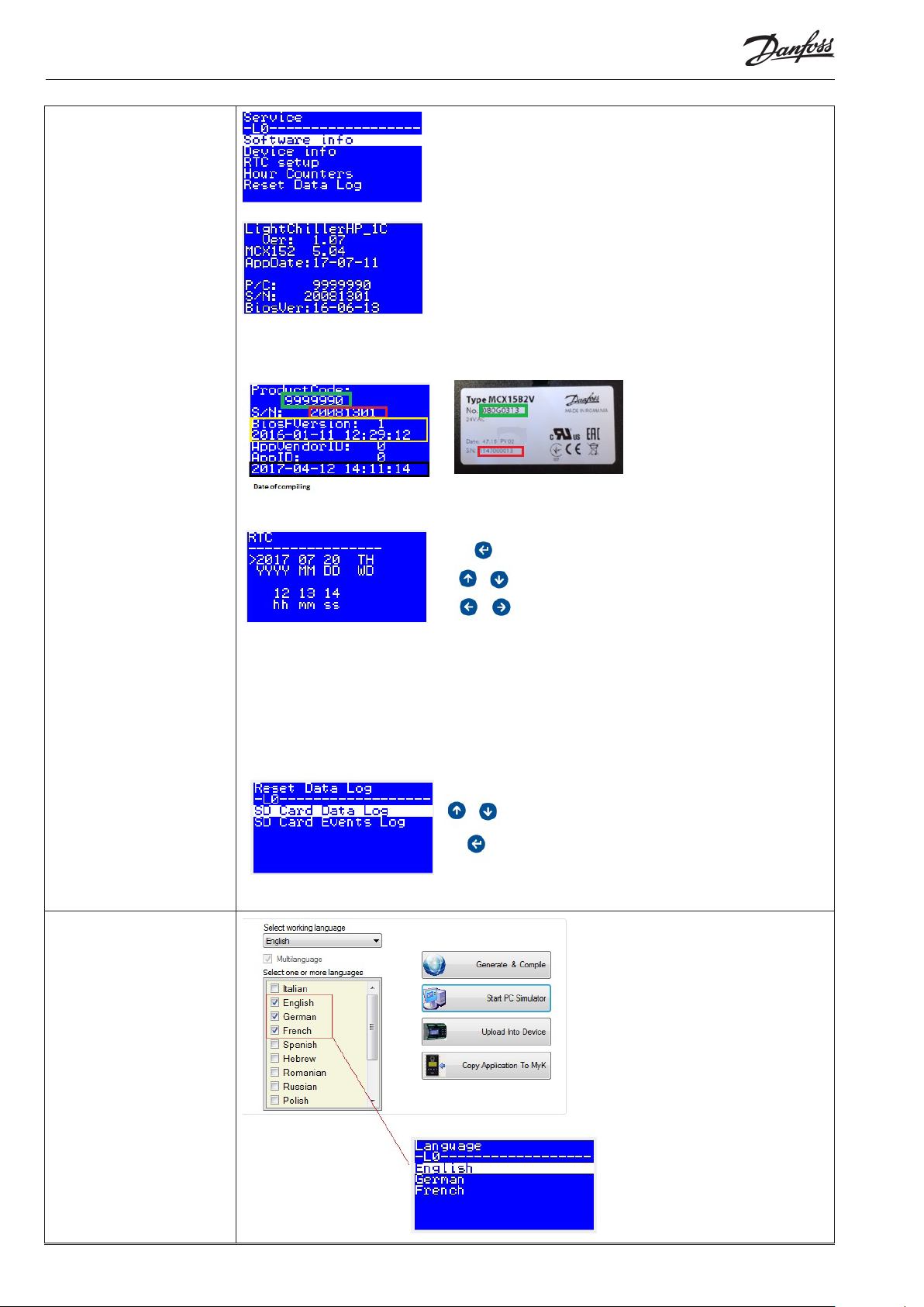
Menu: Service
Software info:
Note: This menu is shown for few seconds just after the power on
Device info:
RtC Setup:
Menu: Language
Hour Counters:
Note: Entering the “Reset Hour Counter” menu will set to zero both the compressors’ hour counters
Reset Data Log:
The Log data is available only for MCXxxxV; about how define the variable to log check parameter
SDL_ Enable SD Card Log
Note: Entering these menus will delete the Data log or the Events log in the SD card memory
6 RS8KB102 © Danfoss 2018-06 Visual Chiller
Page 7
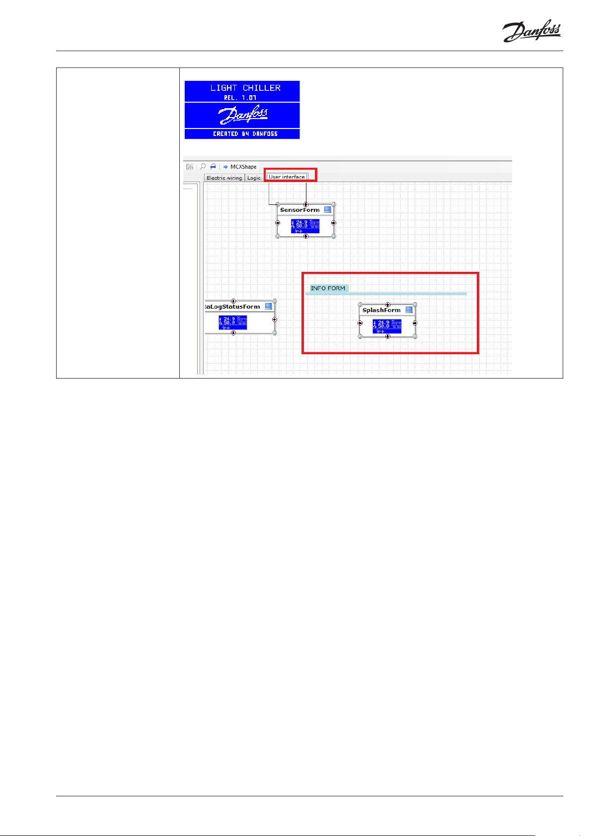
Menu: About This menu is shown for some seconds after the power is turned on
Note: it can be customized from the tab “User Interface” in MCXDesign part
Visual Chiller RS8KB102 © Danfoss 2018-06 7
Page 8
Parameters
SetUp:
Parameter: y01, y03, y07,Cid
How to switch ON-OFF and change the application mode from the
parameters.
y01- System ON/OFF O=OFF
1=ON
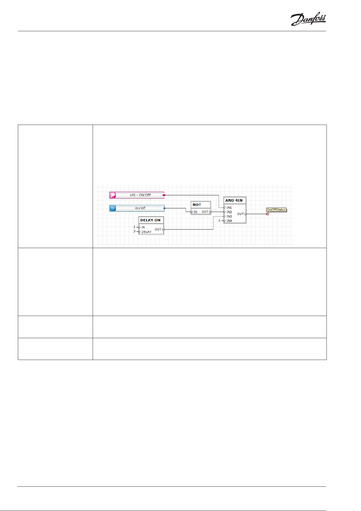
Together with the digital input ON_On/Off the parameter y01 defines whether the machine is in the
ON or OFF state
The parameter y01 can be also changed from the menu/Start, by Modbus or CANBUS and from the
start screen by holding the up-arrow key.
Below the logic that manages the ON-OFF status, the ON status is always delayed by 3 seconds from
the power ON
y03- System heat/cool O=Cool
1=Heat
Together with the digital input DHC_Heat/Cool, the parameter y03 defines whether the machine is in
Cool or Heat mode:
The digital input DHC_Heat/Cool is without predefined meaning, each time that it’ s switched, the
parameter y03 is automatically changed.
Note: It works for H40<> 0
y07- Restore default
parameters
Cid – Serial address (CAN) It defines the ID in the CANBUS communication
0=No means no action
1=Yes means that the default parameters (the ones used in the MCXShape) are loaded
Note: after the restore parameters process, the parameter y07 will be reset to zero
Note: the baud rate and the settings of the CANBUS communication are tuned through the bios
menu or through the MYK
8 RS8KB102 © Danfoss 2018-06 Visual Chiller
Page 9
Buzzer and relay
Parameter: BUZ, Adl, AOF
How to set it up.
BUZ- Buzzer activation time
number
Adl- Alarm relay activation
delay
AOF- Alarm relay active if unit
in off
It is in minutes. It defines the maximum time that the buzzer can work;
BUZ=15 means that there is no limit to the active time of buzzer
It is in seconds. It defines the delay of the alarm relay when there is an alarm
It defines whether the alarm relay works in OFF state of the chiller
Serial setting
Parameter: Cid, Ser, bAU, COM
How to configure the communication port.
SEr – Serial address (Modbus) Defines the ID in the Modbus communication
bAU – Serial baud rate
(Modbus)
COM – Serial settings
(Modbus)
Defines the baud rate in the Modbus communication
0 means Reserved: do not use
1 means 1200 bits/sec
2 means 4200 bits/sec
3 means 4800 bits/sec
4 means 9600 bits/sec
5 means 14400 bits/sec
6 means 19200 bits/sec
5 means 28800 bits/sec
8 means 38400 bits/sec
9 means 57600 bits/sec
8 means 115200 bits/sec
Defines the serial settings of the Modbus communication
0 means 8N1
1 means 8E2
2 means 8N2
Password
Parameter: L01, L02, L03
How to change the password
L01, L02, L03-
Level x password
Visual Chiller RS8KB102 © Danfoss 2018-06 9
Typing the parameter L0x, in the login screen, you will be able to see all the parameters and menu
with level <= of X;
The level of access is highlighted in the yellow square;
Page 10

Unit Configuration
Parameter: H06, H40, HEA
General setting of the fridge circuit
Digital input: C11, C21
Digital output: C11, C21, HC1, HEA
Analogue output: CI1
H06 – Number of compressors
per circuit
H40 – Heat pump type 0=No means that the software doesn’t perform the heating mode
HEA – Enable Heater 0=No means that the heater is not used
It defines the number of compressors in the circuit;
Note: the software manages only one circuit
1=GAS means that the software performs the heating mode, the internal coil acts as evaporator in
cooling mode and condenser in heating mode
1=H2O means that the software performs the heating mode, the coils keep the same function in
both heating and cooling mode
Note: one digital output “HC1_Reverse Valve C1” is reserved for controlling the reverse flow valve
1=Heat the heater is managed by parameters HE1 end HE2
2=Defrost the heater works only during defrost and is managed by parameters HE3 end HE4
3=Both the heater works like HEA=1 and HEA=2
10 RS8KB102 © Danfoss 2018-06 Visual Chiller
Page 11
Temperature Control
Parameter: rEG, rET, Sc1, rC1, SH1, rH1, SdC, SdH, Rin, SOE, SOO
Digital input: SE2
Analogue input: Tin, TOE, SOV
rEG – Analogue input for
temperature regulation
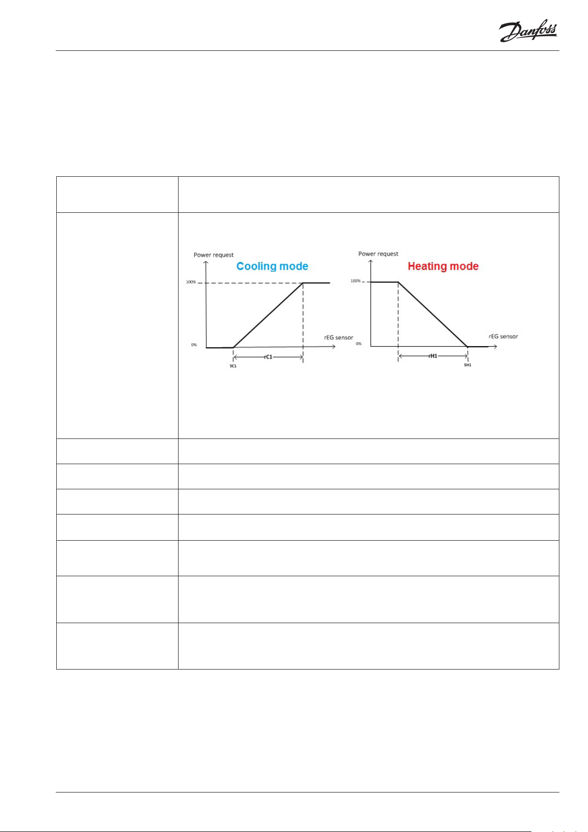
rET – Regulation Type It defines the relation between the temperature gap and the power request to the circuits.
SC1- Cooling temperature
set point
rC1- Cooling temperature
differential.
SH1- heating temperature set
point
rH1- Heating temperature
differential.
Rin- Ti
SdC- Offset for set point in
cooling
SdH- Offset for set point in
heating
0= Tin : reference sensor is Tin_Tin Evaporator
1= TOUT : reference sensor is TOE_Tout Evaporator
0=P : Power request to the circuits increases proportionally with the regulation error, it is 100% when
the regulation error (the gap between set point and the reference sensor ) is equal to rC1 (rH1)
1=PI : the power request is the sum of P regulation (rET=0) more a component (Integral part) that
increases time by time in relation to the regulation error; the speed of the Integral part depends on
the parameter Rin.
In the PI regulation the balance is reached only when the regulation sensor gets to the set point.
It defines the set point in cooling mode
See parameter rET
It defines the set point in heating mode
See parameter rET
It is the integral time of the PI regulation, the bigger the value of Rin slower is the action of the Integral
part.
See parameter rET
In economy status and cooling mode the regulation set point is shift of SdC.
Note: the digital input SE2_Second set point defines if use comfort set point (SC1 or SH1) or the
economy set point (SC1+SdC or SH1-SdH);
In economy status and heating mode the regulation set point is shift of SdH.
Note: the digital input SE2_Second set point defines whether the comfort set point (SC1 or SH1)
or the economy set point (SC1+SdC or SH1-SdH) is used;
Visual Chiller RS8KB102 © Danfoss 2018-06 11
Page 12

SOE- Set point override enable 0=NO means that the function is not enabled
1=Yes means that the regulation set point is defined through the analogue input SOV_Setpoint
Override
set point = main set point + offset from analogue input (SOV_Setpoint Override)
Note: the analogue input SOV has to be mA or Volt type (4-20mA or 0-10V or etc.) and the range
has to be 0-1000
This is because inside the logic we compare AI_SOV within a range of 0-1000
SOO- Set point override offset It is in °C
Check parameter SOE
12 RS8KB102 © Danfoss 2018-06 Visual Chiller
Page 13

Maximum number of compressor starts per hour:
Parameter: CT0, CT1, CT2, CT3, CT4, CT5, CT6, CT7
How to set it up
Digital output: C11, C21
CT0- Minimum time between
2 ON
CT1- Minimum time between
2 OFF
CT2- Minimum OFF time It’s in seconds
CT3- Minimum ON time It’s in seconds
CT4- Minimum time between
2 ONs for same compressor
CTA- Automatic rotation It defines the start order of the compressors
CT5- Max difference in
running hours
CT6- Delay from evaporator
pump/fan
It’s in seconds
It defines the minimum time in between the switch-on of different compressors
It’s in seconds
It defines the minimum time in between the switch-off of different compressors
It does not work for the inverter compressor (IV0=1)
It defines the minimum time that the compressor has to stay switched - OFF
It does not work for the inverter compressor (IV0=1)
It defines the minimum time that the compressor has to stay switched – ON
It’s in seconds
It defines the minimum time in between two starts of the same compressor:
It means that if the compressor started at the 8:00:00, it will be allowed to start again after 8:00:00
past CT2 sec
Note: it’s used for define the maximum number of starts/hour of the compressor
0=No: LIFO means that there is not rotation and the last compressor cut in is the first compressor
cut out, the cut in order is C1,C2…Cn, the cut out order is Cn…C2, C1
2=Yes: tIME means running hours control; the compressor to start is the one with the lowest number
of run hours; the compressor to stop is the one with the highest number of run hours.
It’s in minutes
It works only for “time” rotation (C01=tIME).
If a compressor that is running becomes older than a compressor switched off by more than CT5
minutes, the logic will switch off the oldest compressor running; It will cause the other compressor
to be switched on.
The compressors’ timing (CT0,…CT4) is respected
It’s in seconds
It defines the minimum delay from the evaporator’s pump before allowing the compressors to be
switched on.
Visual Chiller RS8KB102 © Danfoss 2018-06 13
Page 14

Inverter compressor
Parameter: IV0, IV1, IV2, IV4, IV5
The inverter compressor will be switched on first and switched
off last.
The inverter compressor will provide a large range of power.
Below shows the inverter behaviour singly or combined with
another ON-OFF compressors
Digital input: C11
Digital output: C11
Analogue output: CI1
IV0- Inverter enable It enables control of the inverter compressor in the compressor C1
0=No
1=Yes
IV1- Minimum speed It’s in %
It defines the minimum speed of the inverter compressor
IV2- Maximum speed It’s in %
It defines the maximum speed of the inverter compressor
IV4- Minimum ON time It’s in seconds
It works only for inverter compressor (IV0=1)
It defines the minimum time that the compressor has to stay switched - ON
IV5- Minimum OFF time It’s in seconds
It works only for inverter compressor (IV0=1)
It defines the minimum time that the compressor has to stay switched – OFF
14 RS8KB102 © Danfoss 2018-06 Visual Chiller
Page 15

Pump for the internal coil:
Parameter: P01, P02, AFr
The pump EP1_Evaporator pump 1 is switched on when the
chiller is switched on (check parameter y01) or for ice alarm
(check parameter AIA).
The pump EP2_Evaporator pump 2 can be used as backup pump.
Digital output: EP1, EP2
Digital input: P1E, P2E
Alarms: AP1, AP2, A06
Warning: AP3
PO1- Number of evaporator
pumps
PO2- Pump OFF delay from
comp OFF
AFr- Flow switch alarm
reset type
1 means that there is only the pump P1E (back-up pump is not managed)
2 means that in case of alarm of pump P1E the pump P2E is switched-on
It’s in seconds.
It defines the minimum time that the pump has to work after compressor is cut off.
Note: It works after the switch OFF of the machine only if the compressor was running
It ‘s used in the alarm tab in order to set the reset type from the UI
Visual Chiller RS8KB102 © Danfoss 2018-06 15
Page 16

Valve in the liquid line
Parameter: Pd1, Pd2, Pd3, Pd4
Pump down before the circuit’s stop and equalization of
the pressure before circuit’s startup
Digital output: LV1
Digital input: LP1
Analogue input: EP1
Pd1-Pump down enable and
max time
It’s in seconds
0=Disable
>0 defines the maximum pump down time.
The liquid valve LV1 is closed before switching off the last compressor in the circuit.
The compressor will switch off for the following reasons:
• Low pressure switch LP1
• Suction pressure EP1 goes below Pd4 (SPx< Pd4)
• Pd1 seconds have elapsed from LVx closing
• The digital input PDx is closed (manual pump down)
Note: Pump down is not executed in case of alarm
Note: if the sensor SPx is not present it is not considered
Pd4- Pump down pressure set It’s in bar G
If the pressure of the circuit (SPx) goes below Pd4 during the pump down process the compressor is
switched off
Pd2- Compressor ON delay
from liquid valve
Pd3- Start up suction pressure
set
It’s in seconds
Before starting the first compressor in the circuit, the liquid valve is opened in order to decrease the
pressure ratio of the circuit.
The compressor will start for:
• The suction pressure goes above Pd3
• At the maximum after Pd2 seconds from liquid line valve opening
It’s in barG
See parameter Pd2
16 RS8KB102 © Danfoss 2018-06 Visual Chiller
Page 17

Reversing cycle valve (4-way valve):
Parameter: rE1
The working mode of the chiller is defined by parameter y03.
The reversing cycle valve will switch with rE1 seconds delay
from the cut off of the last compressor running
Digital input: DHC
Digital output: HC1
rE1- Change over delay It’s in seconds
rE1=0 means that the compressors are not switched off for switching the 4-way valve
rE1<>0 means that the change of the working mode is performed in 3 steps:
• Switch off all the compressors running
• After rE1 seconds the 4-way valve is switched
• After rE1 seconds the compressors are enabled to work
Compressor’s
status
Visual Chiller RS8KB102 © Danfoss 2018-06 17
Page 18

Defrost:
Parameter: d01, d02, d09, d10, d13, d14, d15, d16, d20, d21
The circuit suction pressure detects the condition to start the
defrost ;
Note: dripping is not performed
Digital output: HC1
Analogue input: dP1, EP1, EXT
d01- Defrost enable 0=NO: disable
1=Yes: means that the defrost is enabled
d02- Defrost type 0=SpEp: means that the defrost is detected and stopped in relation to the pressure sensors
1=SpEt: means that the defrost is detected in relation to the pressure sensor and the defrost is
stopped only after d15 seconds (Defrost maximum time)
d09- Defrost start set point It’s in barG
If the the suction pressure stays below d09 for more than d13 seconds, defrost is detected
d10- Defrost stop set point It’s in barG
If the discharge pressure goes above d10 defrost is completed
Note: it works for d02=0
d13- Defrost temp start
verifying time
d14- Defrost minimum time It’s in sec
d15- Defrost maximum time It’s in minutes
d16- Minimum time 2 defrost
same circuit
d21- Start verifying time It’s in seconds
d22- Start set point It’s in bar
It’s in seconds
Check parameters d09
Counting is stopped but it is not reset when temperature goes beyond that limit d09. Counter is
reset at power ON or when the defrost cycle starts.
The defrost can be switched off only after d14 seconds.
It represents the defrost’s maximum duration, beyond which defrost is stopped and the A13 warning
occurs. This warning is reset after a correct defrost cycle.
Note: If d02=1, parameter d15 defines the defrost duration.
It’s in minutes
It defines the minimum time in between 2 defrost
It’s used to force the start of the defrost
If the pressure stays d21 seconds below d22 the defrost can start
It’s used to force the start of the defrost
If the pressure stays d21 seconds below d22 the defrost can start
18 RS8KB102 © Danfoss 2018-06 Visual Chiller
Page 19

Stepper motor valve setting for SuperHeat control:
Parameter: EEN, bAt, v10, EV0, EV1, EV2, EV3, EV4, EV5, EV6, EV7, EV8, EV9
Internal valve driver (for MCX152V or MCX061V) for the Superheat
control is available.
Note: the superheat algorithm is the same as the EXD external
driver.
Analogue output: ST1, ST2
Alarm: E10, E11
EEN-Electronic Expansion
Valve
v10-Valve 1 type 0=ETS 25
bAt- Enable battery check 0=No
EV0- Valve steps Number of steps from 0% to 100% open
EV1- Valve Nominal Speed Spindle stroke speed (number of steps per second)
EV2- Valve Min Speed It’s in step/sec
EV3- Valve Max Speed It’s in step/sec
EV4- Valve Run Current It’s in mA
EV5- Valve Acceleration
Current
EV6- Valve Hold Current It’s in mA
EV7- Valve Acceleration Rate It’s in Step/sec2
EV8- Valve Decay type 0= Fast
EV9- Valve Stepping type 0=Full Step
0= No means that the MCX stepper motor driver is disabled
1= Yes means that the MCX stepper motor driver is enabled to control the Superheat
It only works for MCX152V or MCX061V
1= ETS 50
2= ETS 100
3= ETS 250
4= ETS 400
5=Custom
6=UKV
It defines the type of valve that will be used.
Only if v10 =5, the valve’s drive setting is by the parameters EV0,…., EV9
1= Yes: if the voltage of the battery goes below 12 V, the alarm E11 EXV battery Fault is generated
Note: Max. steps (100 to 5000 step)
Note: it only works for v10=5
Note: Steps/sec (10 to 500 step/sec)
Note: it only works for v10=5
Note: it only works for v10=5
Note: it only works for v10=5
Note: it only works for v10=5
It’s in mA
Note: it only works for v10=5
Note: it only works for v10=5
Note: it only works for v10=5
Note: we suggest around 5000 steps/sec2
1=Slow
2=Mixed
Note: it only works for v10=5
1=Half Step
2=1/4
3=1/8
4=1/16
Note: it only works for v10=5
Visual Chiller RS8KB102 © Danfoss 2018-06 19
Page 20

SuperHeat control::
Parameter: SH0, N22, N10, N09, N19, N04, N20, N05, N11, N18, N32, N17, N15, N21, o30
Internal valve driver (for MCX152V or MCX061V) for the Superheat
control is available.
Note: the superheat algorithm is the same of EXD external driver.
Analogue input: ET1, ST1
Analogue output: ST1
SH0- Superheat offset It’s in °C
It is an offset that will be added to the Superheat reference (that is calculated in between N09
and N10)
Note: we’ve left it as parameters but please consider also replacing it with a piece of logic in the event
you want to compensate the superheat in special condition
N22- Min superheat ref per
load under 10%
N10- Min superheat reference Warning! Due to the risk of liquid flow, the setting should not be lower than approx. 2-4K.
N09- Max superheat reference
N19- Damping of
amplification factor N04
N04- P Amplification factor Kp The regulation becomes slower if the Kp value is reduced.
N05-Integration time Tn The regulation becomes slower if the tn (N05) value is increased.
N20- Amplification factor for
the SH
N11- MOP point in press
(barG)
20 RS8KB102 © Danfoss 2018-06 Visual Chiller
The value must be smaller than ”N10”
This setting damps the normal amplification Kp (N04), but only just around the reference value.
A setting of 0.5 will reduce the Kp (N04) value by half.
The value should only be changed by specially trained staff.
This setting determines the valve’s opening degree as a function of the change in evaporating
pressure. An increase of the evaporating pressure will result in a reduced opening degree. When
there is a drop-out on the low-pressure thermostat during start-up the value must be raised a bit.
If there is fluctuation during start-up the value must be reduced a little.
The value should only be changed by specially trained staff.
It’s in barG
Page 21

N18- Stability factor for
superheat control
N32- Max valve opening
degree
N17- Signal safety during
start-up
N15- Start-up time for safety
signal
N21- Definition of superheat
control mode
o30 – Gas type 0=---
With a higher value the control function will allow a greater fluctuation of the superheat before the
reference is changed. The value should only be changed by specially trained staff.
The valve’s opening degree can be limited. The value is set in %
The control function uses the value as start value for the valve’s opening degree at each thermostat
cut-in. The controller continuously calculates a new value using adaptive control.
The value should only be changed by specially trained staff.
If the controller does not obtain a reliable signal within this period of time it will try to establish a
stable signal in other ways. (A too high value may result in a flooded evaporator).
The value should only be changed by specially trained staff.
0: The superheat reference is N10
1: Lowest permissible superheat (MSS). Adaptive regulation.
2: Load-defined superheat. The reference is established based on the line formed by the three points:
N09, N10 and N22.
1=R12
2=R22
3=R134a
4=R502
5=R717
6=R13
7=R131b1
8=R23
9=R500
10=R503
11=R114
12=R142b
13=-14=R32
15=R227
16=R401a
17=R507
18=R402a
19=R404a
20= R407c
21= R407a
22= R407b
23= R410a
24= R170
25= R290
26=R600
27= R600a
28= R744
29= R1270
30=R417a
31=R422a
Note: the gas definition is used when the translation of the pressure in temperature is required;
ReG=SPT1 and for the “internal” super heat control
Visual Chiller RS8KB102 © Danfoss 2018-06 21
Page 22

External coil
Parameter: F01, F02, FCS, FCD, FCi, FCd, FHS, FHD, FHi, FHd,
Digital output: IC1
Digital input: FC1
Analogue input: dP1, EP1
Analogue output: FC1
Alarms: AF1, E03, E04
F01- Codensation regulation
type
F02- Regulation type It works for F01=3
FCS- Cooling set point It’s in barG
FCD- Cooling differential It’s in barG
FCI- Cooling integral time It’s in seconds
FCd- Cooling derivate time It’s in seconds
FHS- Heating set point It’s in barG
FHD- Heating differential It’s in barG
FHI- Heating integral time It’s in seconds
FHd- Heating derivate time It’s in seconds
0=OFF means that the fans will not controlled
1= ON means that the fans are always ON. They are switched OFF only when the unit is OFF;
this setting doesn’t work for the analogue output
2=ON_C means that if the circuit is operating, the relevant fans are switched on.
The fans will be switched off F03 seconds after the cut off of the last compressor in the circuit.
3=Prb means that the fans are controlled in relation to the pressure inside the external coil:
Note: check parameters H42 ,ex2 and F10
It defines the type of logic used to manage the fan
0=P means proportional logic
0=PI means proportional logic more an integral part
0=PID means proportional logic more an integral part and more a derivative part
Note: the PID components are defined by the parameters FCi, FCd, FCD, FHi, FHd, FHD,
It’s the set point used for the PID control of the fan, in chiller mode.
Note: it works for F01=Prb
It’s the proportional band of the fan’s PID control, in chiller mode.
Note: it works for F01=Prb
It’s the integral part of the fan’s PID control, in chiller mode.
Note: it works for F01=Prb
It’s the derivate part of the fan’s PID control, in chiller mode.
Note: it works for F01=Prb
It’s the set point used for the PID control of the fan, in heat pump mode.
Note: it works for F01=Prb
It’s the proportional band of the fan’s PID control, in heat pump mode.
Note: it works for F01=Prb
It’s the integral part of the fan’s PID control, in heat pump mode.
Note: it works for F01=Prb
It’s the derivate part of the fan’s PID control, in heat pump mode.
Note: it works for F01=Prb
22 RS8KB102 © Danfoss 2018-06 Visual Chiller
Page 23

Stepless regulation of the fan:
Parameter: F11, F12, F13
Digital output: IC1
Digital input: FC1
Analogue input: dP1, EP1
Analogue output: FC1
Alarms: AF1, E03, E04
F11- Minimum speed It’s in %
It defines the minimum speed of the fan InverterFanCondx (external coil)
Note: check picture above
F12- Maximum speed It’s in %
It defines the maximum speed of the fan InverterFanCondx (external coil)
Note: check picture above
F13- Starting speed It’s in %
The fan is switched ON when the regulation request goes above F13 %;
in the same time it also defines the starting speed of the fan
Visual Chiller RS8KB102 © Danfoss 2018-06 23
Page 24

Heaters:
Parameter: HE1, HE2, HE3, HE4, HE5
The heaters work:
• For regulation (HEA=1 or 3, HE1,HE2)
• For defrost (HEA=2 or 3, HE3,HE4)
• If the unit is switched on
• If the regulation temperature is not in alarm
MCXDesign location:
Digital output: HEA
Analogue input: TIN or TOE
HE1- Heater set point in
heating
HE2- Heater differential in
heating
HE3- Heater set point in
defrost
HE4- Heater differential in
defrost
It’s in °C.
It’s used for parameter HEA=1 or 3.
In heating mode, the heater HEA is switched on when the regulation temperature
(defined by parameter rEG) goes below HE1-HE2
The heater HEA is switched off above HE1
It’s in °C.
Check parameter HE1
It’s in °C.
It’s used for parameter HEA=2 or 3.
In defrost mode, the heater HEA is switched on when the regulation temperature
(defined by parameter rEG) goes below HE3-HE4
The heater HEA is switched off above HE3
It’s in °C.
Check parameter HE3
HE5- Compressor off with
heater in heating
24 RS8KB102 © Danfoss 2018-06 Visual Chiller
0=NO
1=Yes means that when heater is switched on the compressor is switched off
Page 25

ICE alarm:
Parameter: AIT, AID, AIA
Analogue input: TOE
Alarms: A06
AIT- Ice alarm Threshold It’s in °C
If the TOE_ Tout Evaporator temperature goes below AIT °C the alarm A06 is detected.
It the TOE_ Tout Evaporator temperature goes above AIT+AID °C the alarm A06 can be reset
(check the tuning of the alarm in the “Alarm” tab)
Note: The alarm is delayed 4 seconds from the power-on
Note: the alarm is always detected when the chiller is switched off, when the chiller is switched on
the alarm start will be detected after the pump is switched on
Note: check parameter AIA
AID- Differential It’s in °C
Check parameter AIT
AIA- Ice alarm Action With
Unit Off
0=NO : When the ice alarm and machine are in the OFF state the circulation pump is not switched ON
1=PON: When the ice alarm and machine are in the OFF state the circulation pump is switched ON
Visual Chiller RS8KB102 © Danfoss 2018-06 25
Page 26

High pressure alarm:
Parameter: HPE, HPS, HPD
Digital input: HP1
Analogue input: dP1
Alarms: HP1
HPE- Enable HP alarm from
sensor
HPS- High pressure alarm set
point
HPD- High pressure alarm
differential
0=NO: HP1 alarm depends only from the digital input HP1_High Pressure Circuit1
1=Yes: HP1 alarm is triggered by the digital input HP1 or when the analogue input dP1 goes above
HPS bar (check also HPD)
It’s in bar
It’s in bar
If the high pressure dP1 goes below HPS-HPD bar the alarm HP1 is resettable
26 RS8KB102 © Danfoss 2018-06 Visual Chiller
Page 27

Pressure alarms from analogue input:
Parameter: Alr, AL1, LPC, ALE, LPS, LPD
Digital input: LP1
Analogue input: EP1
Alarms: LP1.
Alr- Reset type It ‘s used in the alarm tab in order to set the reset type from the UI
AL1- Delay from compressor
starting
LPC- Enable when compressor
OFF
ALE- Enable LP alarm from
Sensor
LPS- Low pressure alarm set
point
ALd Low pressure alarm
hysteresisLPD- Low pressure
alarm differential
It's in sec
It ‘s used in the alarm tab in order to set the start-up delay from the UI
0=NO means that low pressure alarm is triggered when at least one compressor is switched ON
1=YES means that low pressure alarm is always triggered
0=NO: LP1 alarm depends only from the digital input LP1_High Pressure Circuit1
1=Yes: LP1 alarm is triggered by the digital input HP1 or when the analogue input LP1 goes below
LPS bar (check also LPD)
It’s in bar
It’s in bar
If the low pressure EP1 goes above LPS+LPD bar the alarm LP1 is resettable
Visual Chiller RS8KB102 © Danfoss 2018-06 27
Page 28

Compressor high temperature alarms:
Parameter: HT0, HT1, HT2
Analogue input: DT1, DT2
Alarms: HT1, HT2, E08, E09
Note: the trip alarms of the compressors are generated through
the digital input C11 and C21
HT0- Enable high temperature
alarms
HT1- High temperature
Set point
HT2- High temperature Diff It’s in °C
0= No: the alarms HT1 and HT2 are disabled
1=Yes: when the discharge temperature of the compressor DTx goes above HT1 °C the alarm HTx
is generated
It’s in °C
Note: check parameter HT0
when the discharge temperature of the compressor DTx goes below HT1-HT2 °C the alarm HTx
can be resettable
How to log data into SD card:
Parameter: SDL
It is available only for SD-card-compatible MCXs (MCX152V and
MCX061V).
1-It is possible to start/stop data logging through the parameter
EDL_Enable SD Card Log. If you want to restart the data logger
from zero, it is enough deleting the file into the SD card memory.
The parameter EDL is read just after the power ON, so the
changes of it will have effect only after the power-off of the unit
2-It’ s possible to define the variables to store with the inputs “IN
1-32” of the brick SDCardLog32
28 RS8KB102 © Danfoss 2018-06 Visual Chiller
Page 29

3-The “number of records” for the “Sample time (seconds)”
will define the period covered from the log data
4-For alarms reset of the data log check the menu service
5-The files saved on the SD card can be read through a WEB
connection or using a batch file; however, the file saved on
the internal memory can be read only through WEB.
6- To read the files on the SD card using a decode program,
download the “DecodeLog” folder available on the MCX site
and save it to the C disk.
7- Extract the memory card from the MCX and copy and paste the
files to the SD card in the “DecodeLog/Disck1” folder.
8-
From the “DecodeLog” folder, run the batch file “decodeSDCardLog
it will generate the .csv files with encoded data
”;
Visual Chiller RS8KB102 © Danfoss 2018-06 29
Page 30

9- Events are recorded in the events.csv file. There are six columns:
a. Event time: the time of the event (start alm, stop alm,
parameters change and RTC change)
b. EventNodeID: the ID of the MCX
c. EventType: a numerical description of the event type
i. -2: Reset of MCX history alarm
ii. -3: RTC set
iii. -4: Start alarm
iv. -5: Stop alarm
v. 1000: Parameters change (note: the change can be
detected only when it is made through a user interface)
d. Var1: a numerical description of the variable. To decrypt it, open
the “AGFDefine.c” file in the “App” folder of the MCXDesign
software. In this file there are two sections with an ID indication:
one is for the parameters and the other is for the alarm. If the
event type is 1000, refer to the index parameters list; if the
event type is -4 or -5, refer to the index alarms list. These lists
contain the variable names corresponding to each ID (not to
the variable description – for the variable description, refer to
MCXShape).
30 RS8KB102 © Danfoss 2018-06 Visual Chiller
Page 31

f. Var2: used to record the parameter value before and after
the change. This number is a double integer; in the high part
there is the new parameter value and in the low part there is
the old value.
g. Var3: not used
10- Recorded in the hisdata.csv file are all the variables defined in
MCXDesign in relation to the sample time in the order defined
in the brick.
11- The log of the data can be read directly form the MCXWEB
(Check MCXWeb guide)
EDL- Enable SD card log 0=NO means that the log is stopped
1=YES means that the log is started
Note: If you want to restart the data logger from zero, you only have to delate the file in the SD card
memory
Note: The parameter EDL is read just after the power ON, so the changes of it will have effect only
after the power-off of the unit
Visual Chiller RS8KB102 © Danfoss 2018-06 31
Page 32

Status variables:
The following variables are available through Modbus,
they are the state of the software.
The variables which can work as command are set as
R/W variable
Software status: Status: V01,…,V08, …, V11, …,V20, V22, V24, V26, V28, V29,V31, V34, …, V37,…, V40,V43, V44,V53, …,V57, V59, …, V61, V65, V67, V68, V72, V75, V81,…, V83, V85 C01,…, C04
V01- SystemOnOFF (R)(R) 0: means that the application is switched-OFF
1: means that the application is switched-ON
V02- ActiveDefrostIndex (R)(R) 0: means that defrosting is not needed
1: means that there is request for defrosting or the defrosting is running
V03- ChillerHeatPumpMode(R)(R) 0: means that the heat pump is performing cooling
1: means that the heat pump is performing heating
V04- Enable
CompressorFromInvValve(R)(R)
V05- TinEvaporatorValue (R) It is in °C (*10)
V06
TinEvaporator
Error(R)
V07- Regulation TemperatureValue (R) It is in °C (*10)
V08- Regulation
TemperatureError(R)
V09- Sensor
AlmStatus
(R)
V10- Active
WarningStatus (R)
V11- Active
AlarmStatus (R)
V12- Evaporator
PumpStatus (R)
V13- Current
SetpointValue (R)
V14- Current
DifValue (R)
V15- Enable
Regulation (R)
0: means that the compressors are disabled cause the inversion of the fridge cycle
1: means normal operation
It is the value of the analogue input TIN_Tin Evaporator
0: means no sensor fault
1: means sensor fault
It is the value of the analogue input used for the regulation
Note: Check parameter rEG
0: means no sensor fault
1: means sensor fault
0: means no alarms from DI_General Alarm or DI_External Alarm
1: means that there is an alarm from DI_General Alarm or DI_External Alarm
0: means no warning is active
1: means that there is a warning active
0: means no alarm is active
1: means that there is an alarm active
0: means that the pump is switched off
1: means that the pump is switched on
It is in °C (*10)
It is the value of the set point used for the regulation
It is in °C (*10)
It is the value of the proportional band used for the regulation
0: means that the compressors cannot work
1: means that compressor can work
Note:
Status V15 depends on the variables “SystemOnOff, EvaporatorPumpStart,
EnableCompressorFromInValve and EvapAlarmStopAllOutput”
32 RS8KB102 © Danfoss 2018-06 Visual Chiller
Page 33

V16- DemandValue (R) It is in ‰
It is the power request for the compressors
V17- Compressor
Status (R)
V18- LiquidValve StatusC1 (R) 0: DO_LV1 is Closed
V19- Compressor
1C1Status (R)
V20- Working secCompr1C1(R) It is in seconds
V21- Valve PositionValueC1(R) It is in ‰
V22- EventLog
StatusCode (R)
V23- SDCardDatalog
StatusCode (R)
V24- ExternalCoil
C1Demand (R)
V25- ExtCoil
Status (R)
V26- SuctionTemperatureC1Value (R) It is in °C (*10)
V27- SuctionTemperatureC1Error(R) 0: means no sensor fault
V28- TOutEvaporatorValue (R) It is in °C (*10)
V29- TOutEvaporatorError(R) 0: means no sensor fault
V30- Discarge
PressureC1Value (R)
V31- Discarge
PressureC1Error (R)
V32- Evaporating
PressureC1Value (R)
V33- Evaporating PressureC1Error (R) 0: means no sensor fault
V34- Defrost StatusValue (R)
0: means no compressors are working
1: means that at least one compressor is working
1: DO_LV1 is Opened
0: DO_C11 is Switched off
1: DO_C11 is Switched on
It’s the amount of seconds that the compressor 1 (digital output C11) is been kept switched-on
It’s the requested position of the expansion valve for the Superheat control
Note: it can be different from V42 because of the valve physical movement
It is in ‰
It is the power request for the fan (AO_FC1)
0: DO_IC1 is switched off
1: DO_ IC1 is switched on
It is the value of the AI_ ST1
1: means sensor fault
It is the value of the AI_ TOE
1: means sensor fault
It is in bar (*10)
It is the value of the AI_dP1
0: means no sensor fault
1: means sensor fault
It is in bar (*10)
It is the value of the AI_EP1
1: means sensor fault
V35- MainLoop TimeValue (R) It is in mSeconds
It is the loop time of the software
V36- EvapAlarmStopAllOutput(R) 0: means normal operation
1: means that all the pumps available are in alarm or there is a flow alarm (DI_FSE)
V37- Condenser
SetpointValue (R)
V38- Condenser
SensorValue (R)
V39- SuperHeat ValueC1 (R) It is in °C (*10)
V40- SuperHeat ReferenceC1 (R) It is in °C (*10)
V41- MOP
StatusC1 (R)
V42- ActualValve
PositionEXV1(R)
V43- Cooling serious alarm status (R) 0: means normal operation
Visual Chiller RS8KB102 © Danfoss 2018-06 33
It is in bar (*10)
It is the value of the set point used for the regulation of the external coil
It is in bar (*10)
It is the value of the sensor used for the regulation of the external coil
It is the value of the sensor Superheat
It is the reference of the Superheat
0: means normal operation
1: means that the superheat control is following the MOP
It is in ‰
It’s the position of the expansion valve for the Superheat control
Check also status V26
1: means that the alarm A06_Evaporator ice alarm is active
Page 34

V44- Force Evaporatore pump on (R) 0: means normal operation
1: means that the pump is forced ON cause A06 alarm
Check also parameter AIA
V45- Working secCompr2C1(R) It is in seconds
It’s the amount of seconds that the compressor 2 (digital output C21) is been kept switchedon
V46- Compressor 2C1 status (R) 0: DO_C21 is Switched off
1: DO_C21 is Switched on
V47- Inverter status (R) 0: Inverter compressor DO_C11 is switched off
1: Inverter compressor DO_C11 is switched on
Check also parameters IV0- IV5
V48- Inverter Demand value (R) It is in ‰
It’s the power request for the inverter compressor (analogue output FC1)
Check also parameters IV0- IV5
V49- UI Actual power C1 (R) It is in ‰
It’s the total power request for the compressors
V50- Stage ON C1 (R) 0: No compressors switched on
1: One compressor is switched on
2: Two compressors are switched on
V51- Condensing TemperatureC1
value (R)
V52- Condensing TemperatureC1
error (R)
V53- Evaporating TemperatureC1
value (R)
V54- Evaporating TemperatureC1
error (R)
V55- Discharge Temperature Compr1
value (R)
V56- Discharge Temperature Compr1
error (R)
V57- Discharge Temperature Compr2
value (R)
V58- Discharge Temperature Compr2
error (R)
V59- Forced From heaters
Compr OFF (R)
V60- Heater status (R) 0: DO_HEA is Switched off
V61- External Temperature value (R) It is in °C (*10)
V62- External Temperature error (R) 0: means normal operation
V63- Set point Override value (R) It is in ‰
V64- Set point Overide error (R) 0: means normal operation
V65- Alarm Condenser Fan status (R) 0: DO_IC1 is Switched off
C01- Reset Alarms (R/W) 0: means normal operation, after the writing of 1 or 2 the software will reset zero
It is in °C (*10)
It’s the calculated temperature from the reading of the analogue input dp1_Discharge Pres-
sure C1
0: means normal operation
1: means the fault of the analogue input dp1_Discharge Pressure C1
It is in °C (*10)
It’s the calculated temperature from the reading of the analogue input EP1_Evaporating Pres-
sure C1
0: means normal operation
1: means the fault of the analogue input EP1_Evaporating Pressure C1
It is in °C (*10)
It’s the temperature of the analogue input DT1_Discharge T. Compr. 1
0: means normal operation
1: means the fault of the analogue input DT1_Discharge T. Compr. 1
It is in °C (*10)
It’s the temperature of the analogue input DT2_Discharge T. Compr. 2
0: means normal operation
1: means the fault of the analogue input DT2_Discharge T. Compr. 2
0: means normal operation
1: means that the compressors are not allowed to work because of the heater
1: DO_HEA is Switched on
It’s the temperature of the analogue input EXT_External Temperature
1: means fault in the analogue input EXT_External Temperature
It’s the reading of the analogue input SOV_Set point Override
Check also parameters SdH-SOO
1: means the fault of the analogue input SOV_Set point Override
1: DO_IC1 is Switched on
1: Write 1 to reset the buzzer
2: Enter 2 to reset the active alarms
34 RS8KB102 © Danfoss 2018-06 Visual Chiller
Page 35

C02- Reset hour counters (R/W) 0: means normal operation, after entering 1 the software will reset to zero
1: Enter 1 to reset the hour counters
C03- Event Log Reset (R/W) 0: means normal operation, after entering 1 the software will reset to zero
1: Enter 1 to reset the event log in the SD card
C04- External Log Reset (R/W) 0: means normal operation, after entering 1 the software will reset to zero
1: Enter 1 to reset the data log in the SD card
Visual Chiller RS8KB102 © Danfoss 2018-06 35
Page 36

36 RS8KB102 © Danfoss 2018-06 Visual Chiller
ADAP-KOOL®
 Loading...